radiation isocenter imaging origin coincidence for linac...
TRANSCRIPT
Radiation Isocenter – Imaging Origin Coincidence for
Linac-Based SRS with Novalis TX and RIT October 3, 2015 Charles Geraghty, MS DABR Clinical Medical Physicist Anne Arundel Medical Center
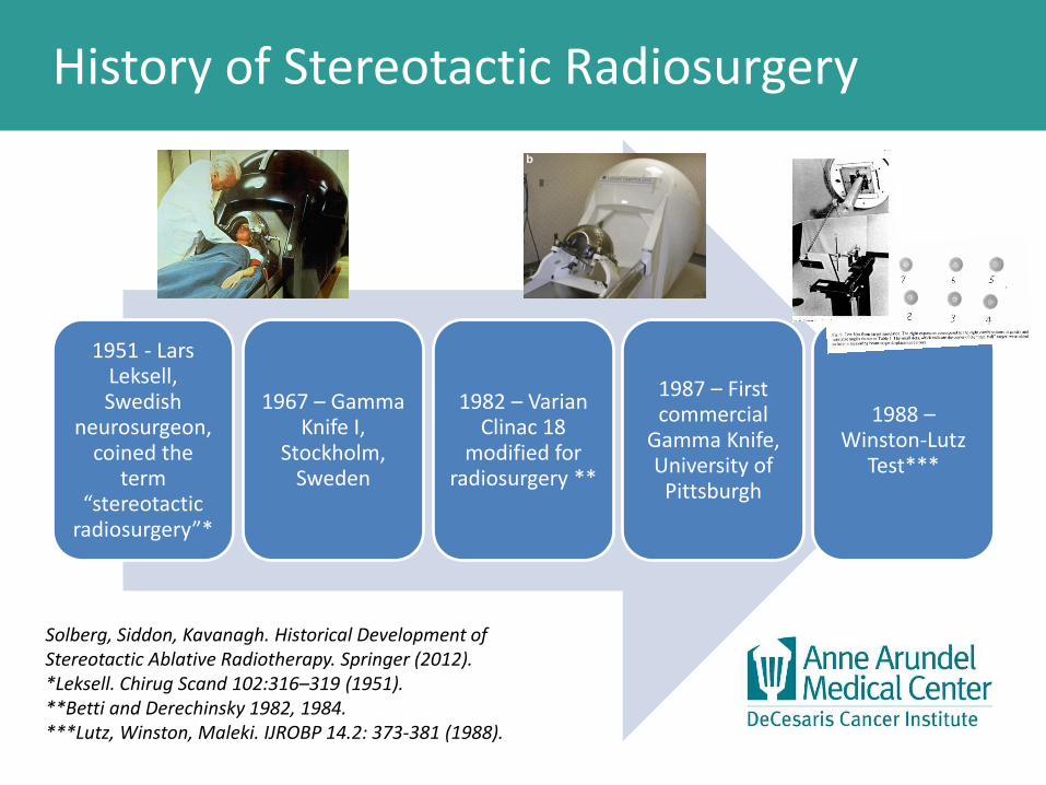
History of Stereotactic Radiosurgery
1951 - Lars Leksell, Swedish
neurosurgeon, coined the
term “stereotactic
radiosurgery”*
1967 – Gamma Knife I,
Stockholm, Sweden
1982 – Varian Clinac 18
modified for radiosurgery **
1987 – First commercial
Gamma Knife, University of
Pittsburgh
1988 – Winston-Lutz
Test***
Solberg, Siddon, Kavanagh. Historical Development of Stereotactic Ablative Radiotherapy. Springer (2012). *Leksell. Chirug Scand 102:316–319 (1951). **Betti and Derechinsky 1982, 1984. ***Lutz, Winston, Maleki. IJROBP 14.2: 373-381 (1988).

History of Stereotactic Radiosurgery
1993-1995 – Cyberknife
robotic radiosurgery developed
1994 – Varian
released the 600SR, a
linac dedicated
for radiosurgery
1997-1999 – microMLCs
concurrently developed
by Radionics, BrainLAB, and Varian
1997 – Room-
mounted orthogonal x-rays for
SRS*
2001 – Dynamic
conformal arc
delivery**
2005-2010 – CBCT
becomes mainstream
in radiotherapy
Solberg, Siddon, Kavanagh. Historical Development of Stereotactic Ablative Radiotherapy. Springer (2012). *Murphy 1997 **Solberg 2001
1st tmt 2015 1st tmt 2015
1st tmt 2009
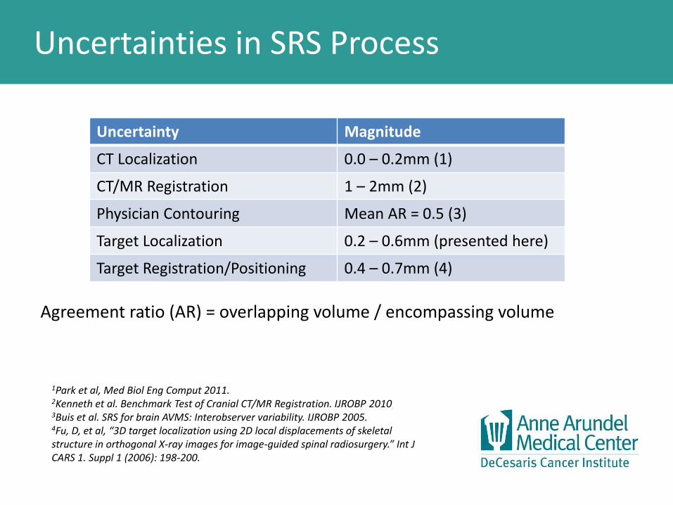
Uncertainties in SRS Process
Agreement ratio (AR) = overlapping volume / encompassing volume
Uncertainty Magnitude
CT Localization 0.0 – 0.2mm (1)
CT/MR Registration 1 – 2mm (2)
Physician Contouring Mean AR = 0.5 (3)
Target Localization 0.2 – 0.6mm (presented here)
Target Registration/Positioning 0.4 – 0.7mm (4)
1Park et al, Med Biol Eng Comput 2011.
2Kenneth et al. Benchmark Test of Cranial CT/MR Registration. IJROBP 2010 3Buis et al. SRS for brain AVMS: Interobserver variability. IJROBP 2005. 4Fu, D, et al, “3D target localization using 2D local displacements of skeletal structure in orthogonal X-ray images for image-guided spinal radiosurgery.” Int J CARS 1. Suppl 1 (2006): 198-200.

Importance of Geometrical Uncertainty
Dose falloff for 7.5mm cone treatment plan. Script dose is 24Gy. 1mm or 2mm from 24Gy to 12Gy line depending upon location.
Distance: 1.0mm

Materials & Methods
• Novalis TX linac-based SRS
• Exactrac imaging – fixed orthogonal x-ray panels
• EPID imaging for radiation source
• RIT software V6.2
• Implemented QA to measure the displacement between radiation isocenter and imaging origin.
• Tracked results over time

Image-Based Winston-Lutz Test
Align Winston-Lutz phantom to room lasers.
Acquire ExacTrac orthogonal x-ray snaps with displacement from imaging origin.
Acquire EPID images at:
• Gantry 0, 90, & 270 w/couch = 0
• Couch 30, 60, 90, 330, 300, 270 w/gantry = 0
Analyze EPID image with RIT V6.2 to obtain displacement from average WL phantom position and radiation isocenter.
Compute the difference between the Exactrac and RIT displacements to find the displacement between radiation isocenter and imaging origin.

Image-Based Winston-Lutz Test
Exactrac snaps w/3D displacements.
Exactrac: VRT: 0.20mm LNG: 0.08mm LAT: 0.17mm

Image-Based Winston-Lutz Test
RIT EPID image analysis, EPID images and calculated shifts

Image-Based Winston-Lutz Test
RIT analysis – axes projections
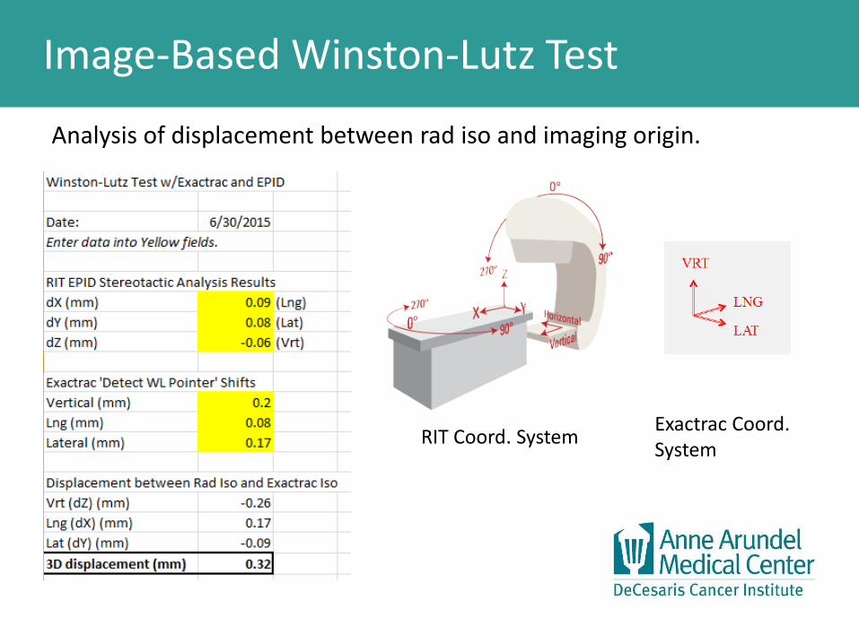
Image-Based Winston-Lutz Test
Analysis of displacement between rad iso and imaging origin.
RIT Coord. System Exactrac Coord. System

Trending of Results
Daily image-based WL test results were tracked and analyzed. The Exactrac calibration is an iterative process and improved with time.
0.00
0.10
0.20
0.30
0.40
0.50
0.60
0.70
0.80
0.90
3/15/2015 5/4/2015 6/23/2015 8/12/2015 10/1/2015
3D
Dis
pla
cem
en
t (m
m)
Displacement from Rad Iso to Exactrac Origin 3D Disp
(mm)
MLC 0.4±0.2
7.5mm 0.3±0.1
10mm 0.4±0.1
12.5mm 0.4±0.3
ALL 0.4±0.2

Cone vs. MLC Isocenter
• EPID images were acquired from MLC and cones with the WL phantom kept at the same location
• Cone and MLC isocenters are different as each is a separate beam collimation device and there is user variability in cone placement.
MLC (baseline) 7.5mm 10mm 12.5mm
DX (LNG) 0 -0.15 -0.26 -0.20
DY (LAT) 0 0.10 0.08 0.07
DZ (VRT) 0 -0.14 -0.23 -0.24
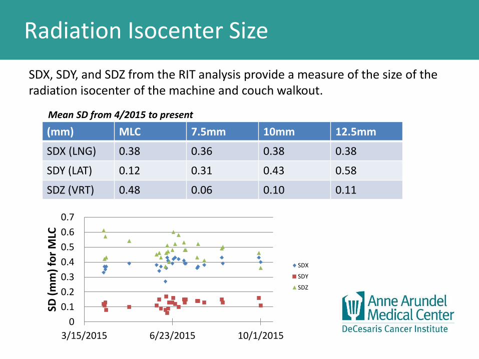
Radiation Isocenter Size
SDX, SDY, and SDZ from the RIT analysis provide a measure of the size of the radiation isocenter of the machine and couch walkout.
(mm) MLC 7.5mm 10mm 12.5mm
SDX (LNG) 0.38 0.36 0.38 0.38
SDY (LAT) 0.12 0.31 0.43 0.58
SDZ (VRT) 0.48 0.06 0.10 0.11
Mean SD from 4/2015 to present
0
0.1
0.2
0.3
0.4
0.5
0.6
0.7
3/15/2015 6/23/2015 10/1/2015
SD (
mm
) fo
r M
LC
SDX
SDY
SDZ

Exactrac 6 New Features
• ‘Radiation Isocenter Calibration’ is a new feature in the latest version of Exactrac - Exactrac 6.
• The isocenter phantom has a radio-opaque sphere in the center and can be used as a Winston-Lutz phantom.
• The radiation isocenter calibration corrects the existing infrared isocenter calibration for the detected Winston-Lutz phantom center.

Exactrac 6 New Features
• X-ray Verification (orthogonal x-ray snaps with repositioning) can be set to be performed at each new couch angle during SRS delivery.
• We are gathering data to compare patient couch angle shifts versus similar WL phantom displacements measured with Exactrac.
Couch Angle (deg) VRT(mm) LNG(mm) LAT(mm)
0 (baseline) 0 0 0
30 -0.01 -0.1 -0.14
60 -0.03 -0.14 -0.38
90 0 0.21 -0.72
330 -0.02 0.29 0.23
300 -0.02 0.42 0.11
270 0 0.61 -0.04
Exactrac WL Displacements vs. Couch Angle

Summary Results
• Mean displacements between ExacTrac origin and radiation isocenter were: VRT: -0.1mm ± 0.3mm, LNG: 0.2mm ± 0.2mm, LAT: 0.0mm ± 0.1mm, 3D displacement: 0.4 ± 0.2mm • Mean displacements decreased over time due to refining calibration
technique and new Exactrac 6 software feature. • Radiation isocenter size was characterized by the mean of the standard
deviations of the WL phantom displacements and varied between MLC and cones:
These measurements established a new baseline of radiation isocenter-imaging origin coincidence.
(mm) MLC 7.5mm 10mm 12.5mm
SDX (LNG) 0.38 0.36 0.38 0.38
SDY (LAT) 0.12 0.31 0.43 0.58
SDZ (VRT) 0.48 0.06 0.10 0.11

Conclusions
• WL tests for image-guided linac-based SRS should be analyzed together with imaging origin since the imaging system is used to position the patient.
• Proposed recommendations for uncertainties in SRS and uniform QA standards would be helpful in image-guided SRS.

Thank You