radiators b2/520 - powerwiki b2-gb.pdf · radiators b2/520 are used to remove the heat generated by...
TRANSCRIPT

ZAKŁADY PRODUKCYJNO-REMONTOWE ENERGETYKI POZNA�
„ENERGETYKA-CZERWONAK”SA 62-004 CZERWONAK . Ul. GDY�SKA 83
RADIATORS B2/520
for oil transformers
TELEFON: 0 PREFIKS – 61 – 8120-081 NIP: 777-00-01-105 TELEFAX: 0 PREFIKS – 61 – 8120-385 REGON: 630363433 E-MAIL: www.energetyka-czerwonak.com.pl [email protected] Czerwonak; lipiec 2004 Egzemplarz nr .................

Strona 2
Zakłady Produkcyjno Remontowe Energetyki Pozna� „ENERGETYKA – CZERWONAK” S.A.
Radiators B2/520 for oil transformers
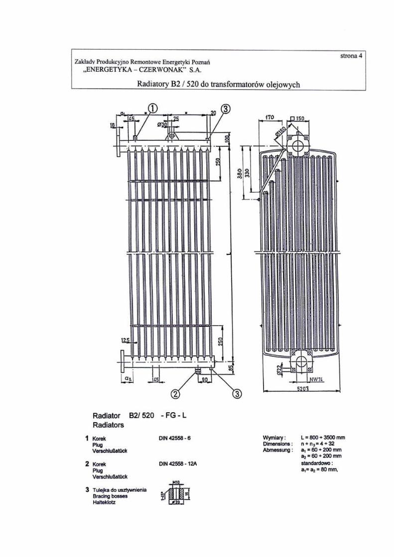
Purpose Radiators B2/520 are used to remove the heat generated by the transformer to the atmosphere. They are used only in oil transformers. Structure Radiators consist of welded fins, drawn from a plate, welded to two collectors. In the top collector there is an eye used for radiator transport and a vent. In the bottom collector there is a drain– plug. At the ends of collectors there are flanges used for fastening radiators to a transformer vat. Radiator fins are stiffened by steel rods. The number and location of rods depend on radiator size and type of surface treatment. Types There are 3 types of top collector shaping:
• straight collector - FG • skew collector - FA • broken collector - FL
and 2 types of fin shaping:
• full fins • cut fins :
�� right – R, ��left – L, ��right and left – B
Materials Radiator fins are made of deep-drawing sheet, collectors of cold bent square pipe and hot rolled sheet. Tests Radiators are tested according to “ W.T.W. i O”. Among other tests there is a leak proof test with compressed air of 0,2 Mpa. Corrosion proofing Radiators are manufactured with the following types of corrosion proofing of outer surfaces:
- painting with oil undercoat - painting with oil undercoat and finish - hot galvanizing - hot galvanizing and painting with oil undercoat and finish


Strona 12
Zakłady Produkcyjno Remontowe Energetyki Pozna� „ENERGETYKA – CZERWONAK” S.A.
Radiators B2/520 for oil transformers
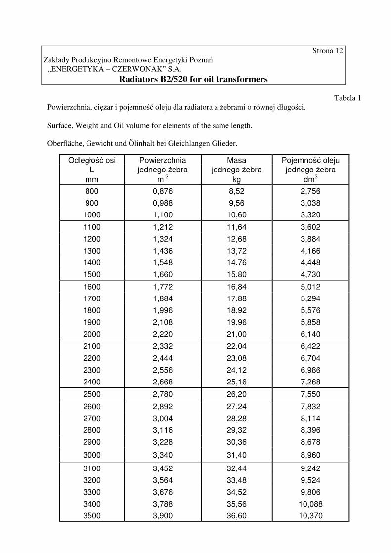
Tabela 1 Powierzchnia, ci��ar i pojemno�� oleju dla radiatora z �ebrami o równej długo�ci. Surface, Weight and Oil volume for elements of the same length. Oberfläche, Gewicht und Ölinhalt bei Gleichlangen Glieder.
Odległo�� osi Powierzchnia Masa Pojemno�� oleju L jednego �ebra jednego �ebra jednego �ebra
mm m 2 kg dm3
800 0,876 8,52 2,756 900 0,988 9,56 3,038
1000 1,100 10,60 3,320
1100 1,212 11,64 3,602 1200 1,324 12,68 3,884 1300 1,436 13,72 4,166 1400 1,548 14,76 4,448 1500 1,660 15,80 4,730
1600 1,772 16,84 5,012 1700 1,884 17,88 5,294 1800 1,996 18,92 5,576 1900 2,108 19,96 5,858 2000 2,220 21,00 6,140
2100 2,332 22,04 6,422 2200 2,444 23,08 6,704 2300 2,556 24,12 6,986 2400 2,668 25,16 7,268
2500 2,780 26,20 7,550
2600 2,892 27,24 7,832 2700 3,004 28,28 8,114 2800 3,116 29,32 8,396 2900 3,228 30,36 8,678
3000 3,340 31,40 8,960
3100 3,452 32,44 9,242 3200 3,564 33,48 9,524 3300 3,676 34,52 9,806 3400 3,788 35,56 10,088 3500 3,900 36,60 10,370

Strona 13 Zakłady Produkcyjno Remontowe Energetyki Pozna� „ ENERGETYKA – CZERWONAK” S.A.
Radiators B2/520 for oil transformers Tabela 2
Zmniejszenie powierzchni, ci��aru i pojemno�ci oleju radiatora przy �ebrach stopniowanych w odniesieniu do �eber o równej długo�ci.
Reduction of surface, weight and oil volume for graded radiators referring to centre distance of elements with same length.
Oberflächen-, Gewichts- und Ölminderung bei abgestuften Gliedern, bezogen auf den Mittenabstand der gleichlangen Glieder.
Liczba stopniowanych �eber Number of graded elements n1 2 3 4 5 6 7 8 9 10 11 12 Anzahl der gestuften Glieder
Ł�czne zmniejszenie powierzchni
Total surface reduction in m2 0,129 0,303 0,549 0,868 1,26 1,725 2,262 2,873 3,556 4,312 5,141
Gesamtoberflächerminderung in
Ł�czne zmniejszenie ci��aru
Total weight reduction in kG 1,20 2,81 5,10 8,06 11,70 16,02 21,01 26,68 33,02 40,04 47,74
Gesamtgewichtsminderung in
Ł�czne zmniejszenie pojemn. oleju
Total oil volume reduction in D m3 0,324 0,761 1,382 2,186 3,173 4,343 5,696 7,233 8,954 10,86 12,94
Gesamtölminderung in Tabela 3
Zmniejszenie powierzchni i ci��aru radiatora dla �eber z obci�tymi sko�nie naro�nikami.
Reduction of surface and weight for sloped elements.
Oberflächen und Gewichtsminderung bei abgeschrägten Glieder.
Liczba �eber obci�tych sko�nie z jednej strony / R i L / Number of elements sloped on one side / R und L / n2 1 2 3 4 5 6 7
Anzahl der einseitig Glieder / R und L /
Ł�czne zmniejszenie powierzchni Total surface reduction in m2 0,05 0,10 0,15 0,20 0,25 0,30 0,35 Gesamtoberflächerminderung in
Ł�czne zmniejszenie masy Total weight reduction in kg 0,49 0,98 1,47 1,96 2,45 2,94 3,43 Gesamtgewichtsminderung in
Liczba �eber obci�tych sko�nie z dwóch stron / B / Number of elements sloped on one side / B / n2 1 2 3 4 5 6 7 Anzahl der einseitig Glieder / B /
Ł�czne zmniejszenie powierzchni Total surface reduction in m2 0,10 0,20 0,30 0,40 0,50 0,60 0,70 Gesamtoberflächerminderung in
Ł�czne zmniejszenie masy Total weight reduction in kg 0,98 1,96 2,94 3,92 4,90 5,88 6,86 Gesamtgewichtsminderung in

Strona 14 Zakłady Produkcyjno Remontowe Energetyki Pozna� „ ENERGETYKA – CZERWONAK” S.A.
Radiators B2/520 for oil transformers
Wydajno�� cieplna radiatorów. Wydajno�� ciepln� radiatorów mo�na okre�li� przy pomocy poni�szego wzoru i przedstawionych
ni�ej wykresów :
npA XXXWFW ⋅⋅⋅⋅= 1
gdzie:
F – powierzchnia radiatora w m2 przy uwzgl�dnieniu danych okre�lonych w tabeli nr 1, 2, 3
W1 – wydajno�� cieplna 1m2 radiatora z wykresu W1
XA – współczynnik uwzgl�dniaj�cy wielko�� transformatora z wykresu W3
Xp – współczynnik uwzgl�dniaj�cy ilo�� zamontowanych na transformatorze radiatorów
z wykresu W4
Xn – współczynnik uwzgl�dniaj�cy liczb� �eber radiatora z wykresu W5
Heat efficiency of radiators. Heat efficiency of radiators is shown by the following diagrams: - diagram W1: W1= f ( L ) shows heat efficiency of a radiator depending on its size
( parameter- collector distance “L” ), including the temperature difference between oil in the upper transformer part and air � T= t1- tp according to diagram W2.
- diagram W2: � T= f (� T ) shows the temperature difference � T between oil in the upper
transformer part (t1 ) and air surrounding the transformer ( tp ), depending on temperature difference � T of oil in the upper t1 and lower t2 transformer parts.
- diagram W3: XA= f (A) shows the value of correcting coefficient XA depending on the distance between axes of transformer core and radiator (A). - diagram W4: Xp= f (P ) shows the value of correcting coefficient Xp depending on the distance between axes of neighbouring radiators (P). - diagram W5: Xn = f (n) shows the value of correcting coefficient Xn depending on the number of radiator fins (n)

Strona 15
"EN
ER
GE
TY
KA
- CZ
ER
WO
NA
K" S.A
.
Zakłady Produkcyjno - R
emontow
e Energetyki Pozna
�
Radiators B
2/520 for oil transformers
300
350
400
450
500
500 1000 1500 2000 2500 3000 3500L [mm]
W1
[W/m2]
18
20
22
24
50 55 60
∆∆∆∆T (t1-tp) [0C]W1
W2
∆∆∆∆t( t1-t2) [0C]
∆∆∆∆t=60 0C
∆∆∆∆t=55 0C
∆∆∆∆t=50 0C
Kd=1

Radiators B2/520 for oil transformers
XA
- współczynnik zale�ny od odległo�ci pomi�dzy osiami rdzenia transformatora i radiatora - A
-coefficient in function of difference in height /A/ between core and center line of the radiator
-koeffizient in abhängigkeit vom abstand /A/ zwischen den mittellinien von kern und radiator
XP-współczynnik zale�ny od odległo�ci pomi�dzy osiami radiatora - P
-coefficient in function of the distance /P/ between the middle of the contiguous radiators
-koeffizient in abhängigkeit vom abstand /P/ zwischen den mittellinien von angrenzenden radiatoren
Xn -współczynnik zale�ny od liczby �eber radiatora - n
-coefficient in function of the radiator elements number /n/
-koeffizient in abhängigkeit vom der anzahl /n/ der radiatorenglieder
ENERGETYKA -CZERWONAK" S.A
strona 16Zakłady Produkcyjno - Remontowe Energetyki Pozna�
0,7
0,8
0,9
1,0
1,1
0 200 400 600 800 1000
W4
0,8
0,9
1,0
1,1
500 600 700 800 900 1000P [mm]
Xp
0,6
0,7
0,8
0,9
1,0
1,1
1,2
0 10 20 30
Xn
n
W3
XA
A [mm]
W5

Strona 17 Zakłady Produkcyjno Remontowe Energetyki Pozna� „ ENERGETYKA – CZERWONAK” S.A.
Radiators B2/520 for oil transformers Marking of radiators. B2/ 520 – radiator sort Radiator type: F – radiator with flanges G – straight upper collector- equal length of fins L – broken upper collector- different length of fins A – skew upper collector- different length of fins
- all fins full ( not cut ) – no marking L – initial left fins cut R - initial right fins cut n3 – number of cut fins L- axes distance: from 800 to 3500 mm every 100 mm L1- axes distance of shorter fins: L-L1 = 100 to 600 mm n – number of fins with L length: n= from 4 to 32 n1 - number of fins with L1 length: min. n1= 3 n2 – number of skew fins - standard distance – no marking a1- distance of upper flange face from the axis of the first fin:
a1= 60 to 250 mm every 5 mm, standard a1 =80 mm a2- distance of lower flange face from the axis of the first fin: a2= 60 to250 mm every 5 mm, standard a2= 80 mm
M – radiator painted with undercoat EP GREEN WITHOUT CHROMATE EPOXY RESIN PRIMER No. 39.0014- 50 and finish coat PUR LIGHT GREY ANSI No. 41.7048- total paint thickness 120 µm Zn – radiator hot galvanized on the outer surface, the thickness of zinc coat min. 55 µm Zn + M- radiator hot galvanized and painted XXX- different paint colour according to RAL

Strona 18 Zakłady Produkcyjno Remontowe Energetyki Pozna� „ ENERGETYKA – CZERWONAK” S.A.
Radiators B2/520 for oil transformers Examples of radiator marking
1. Radiator with straight upper collector and equal length of fins, axes distance L= 180 mm, number of fins n= 16, distance from upper flange face to the axis of the first fin a1 = 80 mm, distance from lower flange face to the axis of the first fin a2= 95 mm, protected from corrosion by hot galvanizing and oil paint:
B2/520 –FG- 18/16- 8,0/9,5- Zn + M
2. Radiator with skew upper collector, different length of full fins, axes distance L1= 2000 mm, number of straight fins n= 15, number of skew fins n2= 4, distance from upper flange face to the axis of the first fin a1 = 80 mm, distance from lower flange face to the axis of the first fin a2= 90 mm, protected from corrosion by hot galvanizing and painting:
B2/520 –FA- 20/15 + 4- 8,0/9,0- Zn + M
3. Radiator with skew upper collector, different length of fins, initial left fins cut n3= 5, axes
distance L1= 2200 mm, number of straight fins n= 20, number of skew fins n2= 6, distance from upper flange face to the axis of the first fin a1 = 85 mm, distance from lower flange face to the axis of the first fin a2= 95 mm, protected from corrosion by hot galvanizing and painting:
B2/520 –FA-L5- 22/20 +6- 8,5/9,5- Zn + M
4. Radiator with skew upper collector, different length of fins, initial right fins cut n3=4, axes
distance L1= 2100 mm, number of straight fins n= 18, number of skew fins n2= 7, distance from upper flange face to the axis of the first fin a1 = 120 mm, distance from lower flange face to the axis of the first fin a2= 150 mm, protected from corrosion by painting:
B2/520 –FA-R4- 21/18 + 5- 120/150- M
Note: It is possible to manufacture any version of radiators after having discussed the structure design. Written by: - Piotr Szarzy�ski- Department of Investment and Development
- Jarosław Łoziak- Department of Marketing and Production Preparation Translated by: - Joanna Grajewska- Department of Marketing and Production Preparation Checked by: - Edmund Stefaniak - Chief Engineer Approved by: - Edward Mi�ko – Technical Director