radio amateur's hand book, the - preppers · · 2017-01-24radio amateur's hand book,...
TRANSCRIPT
Radio Amateur's Hand Book, TheRadio Amateur's Hand Book, TheRadio Amateur's Hand Book, TheCHAPTER<p> I.CHAPTERCHAPTERCHAPTER I<p>CHAPTER ICHAPTER ICHAPTER II<p>CHAPTER IICHAPTER IICHAPTER III<p>CHAPTER IIICHAPTER IIICHAPTER IV<p>CHAPTER IVCHAPTER IVCHAPTER V<p>CHAPTER VCHAPTER VCHAPTER VI<p>CHAPTER VICHAPTER VICHAPTER VII<p>CHAPTER VIICHAPTER VIICHAPTER VIII<p>CHAPTER VIIICHAPTER VIIIChapter III
1
Chapter IIIChapter IIIChapter IIICHAPTER IX<p>CHAPTER IXCHAPTER IXChapter VIII.Chapter VIII.Chapter VIII.Chapter VIII.CHAPTER X<p>CHAPTER XCHAPTER XCHAPTER XI<p>CHAPTER XICHAPTER XICHAPTER XII<p>CHAPTER XIICHAPTER XIICHAPTER XIII<p>CHAPTER XIIICHAPTER XIIICHAPTER XIV<p>CHAPTER XIVCHAPTER XIVCHAPTER XV<p>CHAPTER XVCHAPTER XVChapter XVIII.Chapter XVIII.Chapter XVIII.Chapter XVIII.CHAPTER XVI<p>CHAPTER XVICHAPTER XVICHAPTER XVII<p>CHAPTER XVIICHAPTER XVIICHAPTER XVIII<p>CHAPTER XVIIICHAPTER XVIIICHAPTER XIX<p>CHAPTER XIXCHAPTER XIXCHAPTER XX<p>CHAPTER XXCHAPTER XXInformation about Project GutenbergInformation about Project GutenbergInformation about Project GutenbergThe Legal Small PrintThe Legal Small Print
2
The Legal Small Print
Radio Amateur's Hand Book, TheThe Project Gutenberg EBook of The Radio Amateur's Hand Book
by A. Frederick Collins Copyright laws are changing all over the world. Be sure to check the copyright lawsfor your country before downloading or redistributing this or any other Project Gutenberg eBook.
This header should be the first thing seen when viewing this Project Gutenberg file. Please do not remove it.Do not change or edit the header without written permission.
Please read the "legal small print," and other information about the eBook and Project Gutenberg at thebottom of this file. Included is important information about your specific rights and restrictions in how the filemay be used. You can also find out about how to make a donation to Project Gutenberg, and how to getinvolved.
**Welcome To The World of Free Plain Vanilla Electronic Texts**
**eBooks Readable By Both Humans and By Computers, Since 1971**
*****These eBooks Were Prepared By Thousands of Volunteers!*****
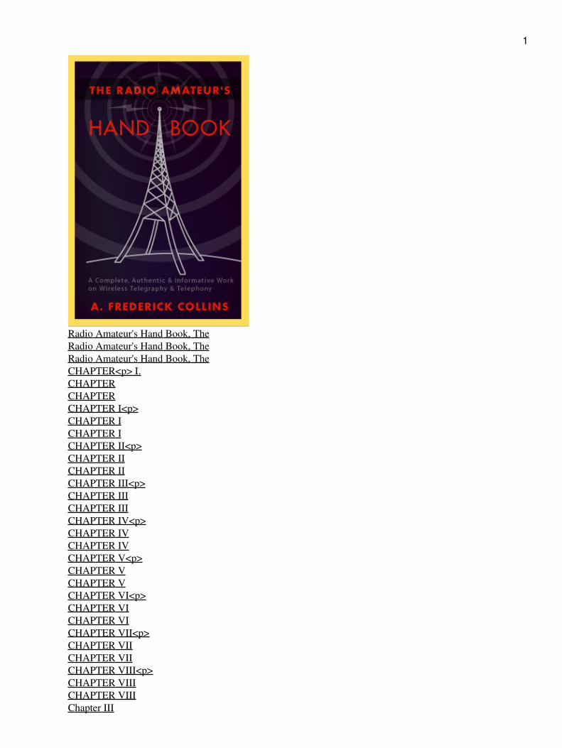
Title: The Radio Amateur's Hand Book
Author: A. Frederick Collins
Release Date: November, 2004 [EBook #6934] [This file was first posted on February 13, 2003]
Edition: 10
Language: English
Character set encoding: ASCII
*** START OF THE PROJECT GUTENBERG EBOOK, THE RADIO AMATEUR'S HAND BOOK ***
Produced by Alan Millar and the Online Distributed Proofreading Team.
[Transcriber's Note: The illustrations have been included with another version of this work. The image fileshave been named in a straightforward manner that corresponds to the numbering in the text; thus, Illustration7 is included as file "fig007.png", while Illustration (A) 22 is included as file "fig022a.png".]
THE RADIO AMATEUR'S HAND BOOK
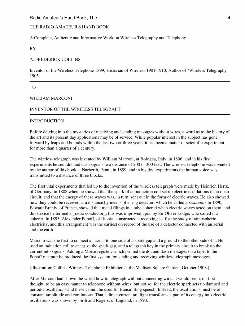
[Illustration: A. Frederick Collins, Inventor of the Wireless Telephone, 1899. Awarded Gold Medal for same,Alaska Yukon Pacific Exposition, 1909.]
Radio Amateur's Hand Book, The 3
THE RADIO AMATEUR'S HAND BOOK
A Complete, Authentic and Informative Work on Wireless Telegraphy and Telephony
BY
A. FREDERICK COLLINS
Inventor of the Wireless Telephone 1899; Historian of Wireless 1901-1910; Author of "Wireless Telegraphy"1905
TO
WILLIAM MARCONI
INVENTOR OF THE WIRELESS TELEGRAPH
INTRODUCTION
Before delving into the mysteries of receiving and sending messages without wires, a word as to the history ofthe art and its present day applications may be of service. While popular interest in the subject has goneforward by leaps and bounds within the last two or three years, it has been a matter of scientific experimentfor more than a quarter of a century.
The wireless telegraph was invented by William Marconi, at Bologna, Italy, in 1896, and in his firstexperiments he sent dot and dash signals to a distance of 200 or 300 feet. The wireless telephone was inventedby the author of this book at Narberth, Penn., in 1899, and in his first experiments the human voice wastransmitted to a distance of three blocks.
The first vital experiments that led up to the invention of the wireless telegraph were made by Heinrich Hertz,of Germany, in 1888 when he showed that the spark of an induction coil set up electric oscillations in an opencircuit, and that the energy of these waves was, in turn, sent out in the form of electric waves. He also showedhow they could be received at a distance by means of a ring detector, which he called a resonator In 1890,Edward Branly, of France, showed that metal filings in a tube cohered when electric waves acted on them, andthis device he termed a _radio conductor_; this was improved upon by Sir Oliver Lodge, who called it acoherer. In 1895, Alexander Popoff, of Russia, constructed a receiving set for the study of atmosphericelectricity, and this arrangement was the earliest on record of the use of a detector connected with an aerialand the earth.
Marconi was the first to connect an aerial to one side of a spark gap and a ground to the other side of it. Heused an induction coil to energize the spark gap, and a telegraph key in the primary circuit to break up thecurrent into signals. Adding a Morse register, which printed the dot and dash messages on a tape, to thePopoff receptor he produced the first system for sending and receiving wireless telegraph messages.
[Illustration: Collins' Wireless Telephone Exhibited at the Madison Square Garden, October 1908.]
After Marconi had shown the world how to telegraph without connecting wires it would seem, on firstthought, to be an easy matter to telephone without wires, but not so, for the electric spark sets up damped andperiodic oscillations and these cannot be used for transmitting speech. Instead, the oscillations must be ofconstant amplitude and continuous. That a direct current arc light transforms a part of its energy into electricoscillations was shown by Firth and Rogers, of England, in 1893.
Radio Amateur's Hand Book, The 4
The author was the first to connect an arc lamp with an aerial and a ground, and to use a microphonetransmitter to modulate the sustained oscillations so set up. The receiving apparatus consisted of a variablecontact, known as a _pill-box_ detector, which Sir Oliver Lodge had devised, and to this was connected anEricsson telephone receiver, then the most sensitive made. A later improvement for setting up sustainedoscillations was the author's rotating oscillation arc.
Since those memorable days of more than two decades ago, wonderful advances have been made in both ofthese methods of transmitting intelligence, and the end is as yet nowhere in sight. Twelve or fifteen years agothe boys began to get fun out of listening-in to what the ship and shore stations were sending and, further, theybegan to do a little sending on their own account. These youngsters, who caused the professional operatorsmany a pang, were the first wireless amateurs, and among them experts were developed who are foremost inthe practice of the art today.
Away back there, the spark coil and the arc lamp were the only known means for setting up oscillations at thesending end, while the electrolytic and crystal detectors were the only available means for the amateur toreceive them. As it was next to impossible for a boy to get a current having a high enough voltage foroperating an oscillation arc lamp, wireless telephony was out of the question for him, so he had to stick to thespark coil transmitter which needed only a battery current to energize it, and this, of course, limited him tosending Morse signals. As the electrolytic detector was cumbersome and required a liquid, the crystal detectorwhich came into being shortly after was just as sensitive and soon displaced the former, even as this haddisplaced the coherer.
A few years ahead of these amateurs, that is to say in 1905, J. A. Fleming, of England, invented the vacuumtube detector, but ten more years elapsed before it was perfected to a point where it could compete with thecrystal detector. Then its use became general and workers everywhere sought to, and did improve it. Further,they found that the vacuum tube would not only act as a detector, but that if energized by a direct current ofhigh voltage it would set up sustained oscillations like the arc lamp, and the value of sustained oscillations forwireless telegraphy as well as wireless telephony had already been discovered.
The fact that the vacuum tube oscillator requires no adjustment of its elements, that its initial cost is much lessthan the oscillation arc, besides other considerations, is the reason that it popularized wireless telephony; andbecause continuous waves have many advantages over periodic oscillations is the reason the vacuum tubeoscillator is replacing the spark coil as a wireless telegraph transmitter. Moreover, by using a number of largetubes in parallel, powerful oscillations can be set up and, hence, the waves sent out are radiated to enormousdistances.
While oscillator tubes were being experimented with in the research laboratories of the General Electric, theWestinghouse, the Radio Corporation of America, and other big companies, all the youthful amateurs in thecountry had learned that by using a vacuum tube as a detector they could easily get messages 500 miles away.The use of these tubes as amplifiers also made it possible to employ a loud speaker, so that a room, a hall, oran out-of-door audience could hear clearly and distinctly everything that was being sent out.
The boy amateur had only to let father or mother listen-in, and they were duly impressed when he told themthey were getting it from KDKA (the Pittsburgh station of the Westinghouse Co.), for was not Pittsburgh 500miles away! And so they, too, became enthusiastic wireless amateurs. This new interest of the grown-ups wasat once met not only by the manufacturers of apparatus with complete receiving and sending sets, but also bythe big companies which began broadcasting regular programs consisting of music and talks on all sorts ofinteresting subjects.
This is the wireless, or radio, as the average amateur knows it today. But it is by no means the limit of itspossibilities. On the contrary, we are just beginning to realize what it may mean to the human race. TheGovernment is now utilizing it to send out weather, crop and market reports. Foreign trade conditions are
Radio Amateur's Hand Book, The 5
being reported. The Naval Observatory at Arlington is wirelessing time signals.
Department stores are beginning to issue programs and advertise by radio! Cities are also taking up suchprograms, and they will doubtless be included soon among the regular privileges of the tax-payers. Politiciansaddress their constituents. Preachers reach the stay-at-homes. Great singers thrill thousands instead ofhundreds. Soon it will be possible to hear the finest musical programs, entertainers, and orators, withoutbudging from one's easy chair.
In the World War wireless proved of inestimable value. Airplanes, instead of flying aimlessly, kept inconstant touch with headquarters. Bodies of troops moved alertly and intelligently. Ships at sea talked freely,over hundreds of miles. Scouts reported. Everywhere its invisible aid was invoked.
In time of peace, however, it has proved and will prove the greatest servant of mankind. Wireless messagesnow go daily from continent to continent, and soon will go around the world with the same facility. Ships indistress at sea can summon aid. Vessels everywhere get the day's news, even to baseball scores. Daily newtasks are being assigned this tireless, wireless messenger.
Messages have been sent and received by moving trains, the Lackawanna and the Rock Island railroads beingpioneers in this field. Messages have also been received by automobiles, and one inventor has successfullydemonstrated a motor car controlled entirely by wireless. This method of communication is being employedmore and more by newspapers. It is also of great service in reporting forest fires.
Colleges are beginning to take up the subject, some of the first being Tufts College, Hunter College,Princeton, Yale, Harvard, and Columbia, which have regularly organized departments for students in wireless.
Instead of the unwieldy and formidable looking apparatus of a short time ago, experimenters are now vyingwith each other in making small or novel equipment. Portable sets of all sorts are being fashioned, from onewhich will go into an ordinary suitcase, to one so small it will easily slip into a Brownie camera. One receiverdepicted in a newspaper was one inch square! Another was a ring for the finger, with a setting one inch byfive-eighths of an inch, and an umbrella as a "ground." Walking sets with receivers fastened to one's belt arealso common. Daily new novelties and marvels are announced.
Meanwhile, the radio amateur to whom this book is addressed may have his share in the joys of wireless. Toget all of these good things out of the ether one does not need a rod or a gun--only a copper wire made fast ateither end and a receiving set of some kind. If you are a sheer beginner, then you must be very careful inbuying your apparatus, for since the great wave of popularity has washed wireless into the hearts of thepeople, numerous companies have sprung up and some of these are selling the veriest kinds of junk.
And how, you may ask, are you going to be able to know the good from the indifferent and bad sets? Bybuying a make of a firm with an established reputation. I have given a few offhand at the end of this book.Obviously there are many others of merit--so many, indeed, that it would be quite impossible to get them allin such a list, but these will serve as a guide until you can choose intelligently for yourself.
A. F. C.
CONTENTS
Radio Amateur's Hand Book, The 6
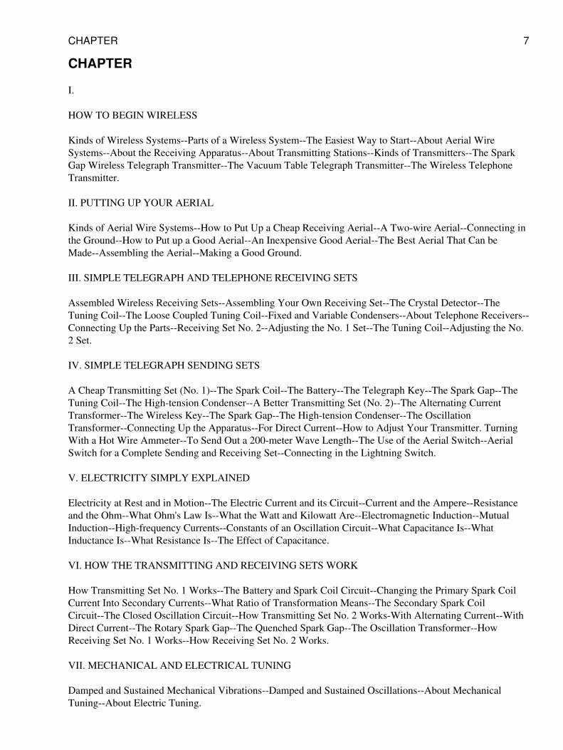
CHAPTER
I.
HOW TO BEGIN WIRELESS
Kinds of Wireless Systems--Parts of a Wireless System--The Easiest Way to Start--About Aerial WireSystems--About the Receiving Apparatus--About Transmitting Stations--Kinds of Transmitters--The SparkGap Wireless Telegraph Transmitter--The Vacuum Table Telegraph Transmitter--The Wireless TelephoneTransmitter.
II. PUTTING UP YOUR AERIAL
Kinds of Aerial Wire Systems--How to Put Up a Cheap Receiving Aerial--A Two-wire Aerial--Connecting inthe Ground--How to Put up a Good Aerial--An Inexpensive Good Aerial--The Best Aerial That Can beMade--Assembling the Aerial--Making a Good Ground.
III. SIMPLE TELEGRAPH AND TELEPHONE RECEIVING SETS
Assembled Wireless Receiving Sets--Assembling Your Own Receiving Set--The Crystal Detector--TheTuning Coil--The Loose Coupled Tuning Coil--Fixed and Variable Condensers--About Telephone Receivers--Connecting Up the Parts--Receiving Set No. 2--Adjusting the No. 1 Set--The Tuning Coil--Adjusting the No.2 Set.
IV. SIMPLE TELEGRAPH SENDING SETS
A Cheap Transmitting Set (No. 1)--The Spark Coil--The Battery--The Telegraph Key--The Spark Gap--TheTuning Coil--The High-tension Condenser--A Better Transmitting Set (No. 2)--The Alternating CurrentTransformer--The Wireless Key--The Spark Gap--The High-tension Condenser--The OscillationTransformer--Connecting Up the Apparatus--For Direct Current--How to Adjust Your Transmitter. TurningWith a Hot Wire Ammeter--To Send Out a 200-meter Wave Length--The Use of the Aerial Switch--AerialSwitch for a Complete Sending and Receiving Set--Connecting in the Lightning Switch.
V. ELECTRICITY SIMPLY EXPLAINED
Electricity at Rest and in Motion--The Electric Current and its Circuit--Current and the Ampere--Resistanceand the Ohm--What Ohm's Law Is--What the Watt and Kilowatt Are--Electromagnetic Induction--MutualInduction--High-frequency Currents--Constants of an Oscillation Circuit--What Capacitance Is--WhatInductance Is--What Resistance Is--The Effect of Capacitance.
VI. HOW THE TRANSMITTING AND RECEIVING SETS WORK
How Transmitting Set No. 1 Works--The Battery and Spark Coil Circuit--Changing the Primary Spark CoilCurrent Into Secondary Currents--What Ratio of Transformation Means--The Secondary Spark CoilCircuit--The Closed Oscillation Circuit--How Transmitting Set No. 2 Works-With Alternating Current--WithDirect Current--The Rotary Spark Gap--The Quenched Spark Gap--The Oscillation Transformer--HowReceiving Set No. 1 Works--How Receiving Set No. 2 Works.
VII. MECHANICAL AND ELECTRICAL TUNING
Damped and Sustained Mechanical Vibrations--Damped and Sustained Oscillations--About MechanicalTuning--About Electric Tuning.
CHAPTER 7
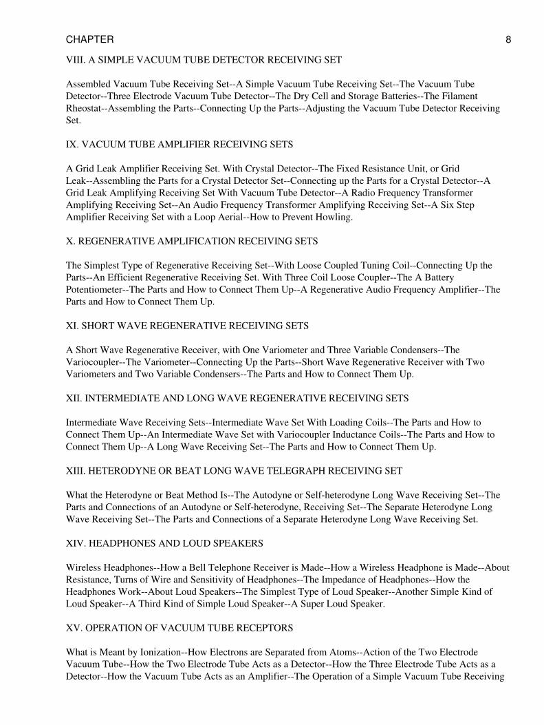
VIII. A SIMPLE VACUUM TUBE DETECTOR RECEIVING SET
Assembled Vacuum Tube Receiving Set--A Simple Vacuum Tube Receiving Set--The Vacuum TubeDetector--Three Electrode Vacuum Tube Detector--The Dry Cell and Storage Batteries--The FilamentRheostat--Assembling the Parts--Connecting Up the Parts--Adjusting the Vacuum Tube Detector ReceivingSet.
IX. VACUUM TUBE AMPLIFIER RECEIVING SETS
A Grid Leak Amplifier Receiving Set. With Crystal Detector--The Fixed Resistance Unit, or GridLeak--Assembling the Parts for a Crystal Detector Set--Connecting up the Parts for a Crystal Detector--AGrid Leak Amplifying Receiving Set With Vacuum Tube Detector--A Radio Frequency TransformerAmplifying Receiving Set--An Audio Frequency Transformer Amplifying Receiving Set--A Six StepAmplifier Receiving Set with a Loop Aerial--How to Prevent Howling.
X. REGENERATIVE AMPLIFICATION RECEIVING SETS
The Simplest Type of Regenerative Receiving Set--With Loose Coupled Tuning Coil--Connecting Up theParts--An Efficient Regenerative Receiving Set. With Three Coil Loose Coupler--The A BatteryPotentiometer--The Parts and How to Connect Them Up--A Regenerative Audio Frequency Amplifier--TheParts and How to Connect Them Up.
XI. SHORT WAVE REGENERATIVE RECEIVING SETS
A Short Wave Regenerative Receiver, with One Variometer and Three Variable Condensers--TheVariocoupler--The Variometer--Connecting Up the Parts--Short Wave Regenerative Receiver with TwoVariometers and Two Variable Condensers--The Parts and How to Connect Them Up.
XII. INTERMEDIATE AND LONG WAVE REGENERATIVE RECEIVING SETS
Intermediate Wave Receiving Sets--Intermediate Wave Set With Loading Coils--The Parts and How toConnect Them Up--An Intermediate Wave Set with Variocoupler Inductance Coils--The Parts and How toConnect Them Up--A Long Wave Receiving Set--The Parts and How to Connect Them Up.
XIII. HETERODYNE OR BEAT LONG WAVE TELEGRAPH RECEIVING SET
What the Heterodyne or Beat Method Is--The Autodyne or Self-heterodyne Long Wave Receiving Set--TheParts and Connections of an Autodyne or Self-heterodyne, Receiving Set--The Separate Heterodyne LongWave Receiving Set--The Parts and Connections of a Separate Heterodyne Long Wave Receiving Set.
XIV. HEADPHONES AND LOUD SPEAKERS
Wireless Headphones--How a Bell Telephone Receiver is Made--How a Wireless Headphone is Made--AboutResistance, Turns of Wire and Sensitivity of Headphones--The Impedance of Headphones--How theHeadphones Work--About Loud Speakers--The Simplest Type of Loud Speaker--Another Simple Kind ofLoud Speaker--A Third Kind of Simple Loud Speaker--A Super Loud Speaker.
XV. OPERATION OF VACUUM TUBE RECEPTORS
What is Meant by Ionization--How Electrons are Separated from Atoms--Action of the Two ElectrodeVacuum Tube--How the Two Electrode Tube Acts as a Detector--How the Three Electrode Tube Acts as aDetector--How the Vacuum Tube Acts as an Amplifier--The Operation of a Simple Vacuum Tube Receiving
CHAPTER 8
Set--Operation of a Regenerative Vacuum Tube Receiving Set--Operation of Autodyne and HeterodyneReceiving Sets--The Autodyne, or Self-Heterodyne Receiving Set--The Separate Heterodyne Receiving Set.
XVI. CONTINUOUS WAVE TELEGRAPH TRANSMITTING SETS WITH DIRECT CURRENT
Sources of Current for Telegraph Transmitting Sets--An Experimental Continuous Wave TelegraphTransmitter--The Apparatus You Need--The Tuning Coil--The Condensers--The Aerial Ammeter--TheBuzzer and Dry Cell--The Telegraph Key--The Vacuum Tube Oscillator--The Storage Battery--The BatteryRheostat--The Oscillation Choke Coil--Transmitter Connectors--The Panel Cutout--Connecting Up theTransmitting Apparatus--A 100-mile C. W. Telegraph Transmitter--The Apparatus You Need--The TuningCoil--The Aerial Condenser--The Aerial Ammeter--The Grid and Blocking Condensers--The Key CircuitApparatus--The 5 Watt Oscillator Vacuum Tube--The Storage Battery and Rheostat--The FilamentVoltmeter--The Oscillation Choke Coil--The Motor-generator Set--The Panel Cut-out--The ProtectiveCondenser--Connecting Up the Transmitting Apparatus--A 200-mile C. W. Telegraph Transmitter--A500-mile C. W. Telegraph Transmitter--The Apparatus and Connections-- The 50-watt Vacuum TubeOscillator--The Aerial Ammeter--The Grid Leak Resistance--The Oscillation Choke Coil--The FilamentRheostat--The Filament Storage Battery--The Protective Condenser--The Motor-generator--A 1000-mile C.W. Telegraph Transmitter.
XVII. CONTINUOUS WAVE TELEGRAPH TRANSMITTING SETS WITH ALTERNATING CURRENT
A 100-mile C. W. Telegraph Transmitting Set--The Apparatus Required--The Choke Coils--TheMilli-ammeter--The A. C. Power Transformer--Connecting Up the Apparatus--A 200- to 500-mile C. W.Telegraph Transmitting Set-A 500- to 1000-mile C. W. Telegraph Transmitting Set--The ApparatusRequired--The Alternating Current Power Transformer-Connecting Up the Apparatus.
XVIII. WIRELESS TELEPHONE TRANSMITTING SETS WITH DIRECT AND ALTERNATINGCURRENTS
A Short Distance Wireless Telephone Transmitting Set--With 110-volt Direct Lighting Current--TheApparatus You Need--The Microphone Transmitter--Connecting Up the Apparatus--A 25- to 50-mileWireless Telephone Transmitter--With Direct Current Motor Generator--The Apparatus You Need--TheTelephone Induction Coil--The Microphone Transformer--The Magnetic Modulator--How the Apparatus isConnected Up--A 50- to 100-mile Wireless Telephone Transmitter--With Direct Current MotorGenerator--The Oscillation Choke Coil--The Plate and Grid Circuit Reactance Coils--Connecting up theApparatus--A 100- to 200-mile Wireless Telephone Transmitter--With Direct Current Motor Generator--A50- to 100-mile Wireless Telephone Transmitting Set--With 100-volt Alternating Current--The ApparatusYou Need--The Vacuum Tube Rectifier--The Filter Condensers--The Filter Reactance Coil-- Connecting Upthe Apparatus--A 100- to 200-mile Wireless Telephone Transmitting Set--With 110-volt AlternatingCurrent--Apparatus Required.
XIX. THE OPERATION OF VACUUM TUBE TRANSMITTERS
The Operation of the Vacuum Tube Oscillator--The Operation of C. W. Telegraph Transmitters with DirectCurrent--Short Distance C. W. Transmitter--The Operation of the Key Circuit--The Operation of C. W.Telegraph Transmitting with Direct Current--The Operation of C. W. Telegraph Transmitters with AlternatingCurrent--With a Single Oscillator Tube--Heating the Filament with Alternating Current--The Operation of C.W. Telegraph Transmitters with Alternating Current-- With Two Oscillator Tubes--The Operation of WirelessTelephone Transmitters with Direct Current--Short Distance Transmitter--The Microphone Transmitter--TheOperation of Wireless Telephone Transmitters with Direct Current--Long Distance Transmitters--TheOperation of Microphone Modulators--The Induction Coil--The Microphone Transformer--The MagneticModulator--Operation of the Vacuum Tube as a Modulator--The Operation of Wireless Telephone
CHAPTER 9
Transmitters with Alternating Current--The Operation of Rectifier Vacuum Tubes--The Operation of Reactorsand Condensers.
XX. HOW TO MAKE A RECEIVING SET FOR $5.00 OR LESS.
The Crystal Detector--The Tuning Coil--The Headphone--How to Mount the Parts--The Condenser--How toConnect Up the Receptor.
APPENDIX
Useful Information--Glossary--Wireless Don'ts.
LIST OF FIGURES
Fig. 1.--Simple Receiving Set
Fig. 2.--Simple Transmitting Set
(A) Fig. 3.--Flat Top, or Horizontal Aerial
(B) Fig. 3.--Inclined Aerial
(A) Fig. 4.--Inverted L Aerial
(B) Fig. 4--T Aerial
Fig. 5.--Material for a Simple Aerial Wire System
(A) Fig. 6.--Single Wire Aerial for Receiving
(B) Fig. 6.--Receiving Aerial with Spark Gap Lightning Arrester
(C) Fig. 6.--Aerial with Lightning Switch
Fig. 7.--Two-wire Aerial
(A) Fig. 8.--Part of a Good Aerial
(B) Fig. 8.--The Spreaders
(A) Fig. 9.--The Middle Spreader
(B) Fig. 9.--One End of Aerial Complete
(C) Fig. 9.--The Leading in Spreader
(A) Fig. 10.--Cross Section of Crystal Detector
(B) Fig. 10.--The Crystal Detector Complete
(A) Fig. 11.--Schematic Diagram of a Double Slide Tuning Coil
CHAPTER 10
(B) Fig. 11.--Double Slide Tuning Coil Complete
(A) Fig. 12.--Schematic Diagram of a Loose Coupler
(B) Fig. 12.--Loose Coupler Complete
(A) Fig. 13.--How a Fixed Receiving Condenser is Built up
(B) Fig. 13.--The Fixed Condenser Complete
(C) and (D) Fig. 13.--Variable Rotary Condenser
Fig. 14.--Pair of Wireless Headphones
(A) Fig. 15.--Top View of Apparatus Layout for Receiving Set No. 1
(B) Fig. 15.--Wiring Diagram for Receiving Set No. 1
(A) Fig. 16.--Top View of Apparatus Layout for Receiving Set No. 2
(B) Fig. 16.--Wiring Diagram for Receiving Set No. 2
Fig. 17.--Adjusting the Receiving Set
(A) and (B) Fig. 18.--Types of Spark Coils for Set No. 1
(C) Fig. 18.--Wiring Diagram of Spark Coil
Fig. 19.--Other Parts for Transmitting Set No. 1
(A) Fig. 20.--Top View of Apparatus Layout for Sending Set No. 1
(B) Fig. 20.--Wiring of Diagram for Sending Set No. 1
Fig. 21.--Parts for Transmitting Set No. 2
(A) Fig. 22.--Top View of Apparatus Layout for Sending Set No. 2
(B) Fig. 22.--Wiring Diagram for Sending Set No. 2
Fig. 23.--Using a 110-volt Direct Current with an Alternating current Transformer
Fig. 24.--Principle of the Hot Wire Ammeter
Fig. 25.--Kinds of Aerial Switches
Fig. 26.--Wiring Diagram for a Complete Sending and Receiving Set No. 1
Fig. 27.--Wiring Diagram for Complete Sending and Receiving Set No. 2
Fig. 28.--Water Analogue for Electric Pressure
CHAPTER 11
Fig. 29.--Water Analogues for Direct and Alternating Currents
Fig. 30.--How the Ammeter and Voltmeter are Used
Fig. 31.--Water Valve Analogue of Electric Resistance
(A) and (B) Fig. 32.--How an Electric Current is Changed into Magnetic Lines of Force and These into anElectric Current
(C) and (D) Fig. 32.--How an Electric Current Sets up a Magnetic Field
Fig. 33.--The Effect of Resistance on the Discharge of an Electric Current
Fig. 34.--Damped and Sustained Mechanical Vibrations
Fig. 35.--Damped and Sustained Electric Oscillations
Fig. 36.--Sound Wave and Electric Wave Tuned Senders and Receptors
Fig. 37.--Two Electrode Vacuum Tube Detectors
Fig. 38.--Three Electrode Vacuum Tube Detector and Battery Connections
Fig. 39.--A and B Batteries for Vacuum Tube Detectors
Fig. 40.--Rheostat for the A or Storage-battery Current
(A) Fig. 41.--Top View of Apparatus Layout for Vacuum Tube Detector Receiving Set
(B) Fig. 41.--Wiring Diagram of a Simple Vacuum Tube Receiving Set
Fig. 42.--Grid Leaks and How to Connect them Up
Fig. 43.--Crystal Detector Receiving Set with Vacuum Tube Amplifier (Resistance Coupled)
(A) Fig. 44.--Vacuum Tube Detector Receiving Set with One Step Amplifier (Resistance Coupled)
(B) Fig. 44.--Wiring Diagram for Using One A or Storage Battery with an Amplifier and a Detector Tube
(A) Fig. 45.--Wiring Diagram for Radio Frequency Transformer Amplifying Receiving Set
(B) Fig. 45.--Radio Frequency Transformer
(A) Fig. 46.--Audio Frequency Transformer
(B) Fig. 46.--Wiring Diagram for Audio Frequency Transformer Amplifying Receiving Set. (With VacuumTube Detector and Two Step Amplifier Tubes)
(A) Fig. 47.--Six Step Amplifier with Loop Aerial
(B) Fig. 47.--Efficient Regenerative Receiving Set (With Three Coil Loose Coupler Tuner)
CHAPTER 12
Fig. 48.--Simple Regenerative Receiving Set (With Loose Coupler Tuner)
(A) Fig. 49.--Diagram of Three Coil Loose Coupler
(B) Fig. 49.--Three Coil Loose Coupler Tuner
Fig. 50.--Honeycomb Inductance Coil
Fig. 51.--The Use of the Potentiometer
Fig. 52.--Regenerative Audio Frequency Amplifier Receiving Set
Fig. 53.--How the Vario Coupler is Made and Works
Fig. 54.--How the Variometer is Made and Works
Fig. 55.--Short Wave Regenerative Receiving Set (One Variometer and Three Variable Condensers)
Fig. 56.--Short Wave Regenerative Receiving Set (Two Variometer and Two Variable Condensers)
Fig. 57.--Wiring Diagram Showing Fixed Loading Coils for Intermediate Wave Set
Fig. 58.--Wiring Digram of Intermediate Wave Receptor with One Vario Coupler and 12 Section Bank-woundInductance Coil
Fig. 59.--Wiring Diagram Showing Long Wave Receptor with Vario Couplers and 8 Bank-wound InductanceCoils
Fig. 60.--Wiring Diagram of Long Wave Autodyne, or Self-heterodyne Receptor (Compare with Fig. 77)
Fig. 61.--Wiring Diagram of Long Wave Separate Heterodyne Receiving Set
Fig. 62.--Cross Section of Bell Telephone Receiver
Fig. 63.--Cross Section of Wireless Headphone
Fig. 64.--The Wireless Headphone
Fig. 65.--Arkay Loud Speaker
Fig. 66.--Amplitone Loud Speaker
Fig. 67.--Amplitron Loud Speaker
Fig. 68.--Magnavox Loud Speaker
Fig. 69.--Schematic Diagram of an Atom
Fig. 70.--Action of Two-electrode Vacuum Tube
(A) and (B) Fig. 71.--How a Two-electrode Tube Acts as Relay or a Detector
CHAPTER 13
(C) Fig. 71--Only the Positive Part of Oscillations Goes through the Tube
(A) and (B) Fig. 72.--How the Positive and Negative Voltages of the Oscillations Act on the Electrons
(C) Fig. 72.--How the Three-electrode Tube Acts as Detector and Amplifier
(D) Fig. 72.--How the Oscillations Control the Flow of the Battery Current through the Tube
Fig. 73.--How the Heterodyne Receptor Works
Fig. 74.--Separate Heterodyne Oscillator
(A) Fig. 75.--Apparatus for Experimental C. W. Telegraph Transmitter.
(B) Fig. 75.--Apparatus for Experimental C. W. Telegraph Transmitter.
Fig. 76.--Experimental C. W. Telegraph Transmitter
Fig. 77--Apparatus of 100-mile C. W. Telegraph Transmitter
Fig. 78.--5- to 50-watt C. W. Telegraph Transmitter (with a Single Oscillation Tube)
Fig. 79.--200-mile C. W. Telegraph Transmitter (with Two Tubes in Parallel)
Fig. 80.--50-watt Oscillator Vacuum Tube
Fig. 81.--Alternating Current Power Transformer (for C. W. Telegraphy and Wireless Telephony)
Fig. 82.--Wiring Diagram for 200- to 500-mile C. W. Telegraph Transmitting Set. (With Alternating Current.)
Fig. 83--Wiring Diagram for 500- to 1000-mile C. W. Telegraph Transmitter
Fig. 84.--Standard Microphone Transmitter
Fig. 85.--Wiring Diagram of Short Distance Wireless Telephone Set. (Microphone in Aerial Wire.)
Fig. 86.--Telephone Induction Coil (used with Microphone Transmitter).
Fig. 87.--Microphone Transformer Used with Microphone Transmitter
Fig. 88.--Magnetic Modulator Used with Microphone Transmitter
(A) Fig. 89.--Wiring Diagram of 25--to 50-mile Wireless Telephone. (Microphone Modulator ShuntedAround Grid-leak Condenser)
(B) Fig. 89.--Microphone Modulator Connected in Aerial Wire
Fig. 90.--Wiring Diagram of 50- to 100-mile Wireless Telephone Transmitting Set
Fig. 91.--Plate and Grid Circuit Reactor
Fig. 92.--Filter Reactor for Smoothing Out Rectified Currents
CHAPTER 14
Fig. 93.--100- to 200-mile Wireless Telephone Transmitter
(A) and (B) Fig. 94.--Operation of Vacuum Tube Oscillators
(C) Fig. 94.--How a Direct Current Sets up Oscillations
Fig. 95.--Positive Voltage Only Sets up Oscillations
Fig. 96.--Rasco Baby Crystal Detector
Fig. 97.--How the Tuning Coil is Made
Fig. 98.--Mesco loop-ohm Head Set
Fig. 99.--Schematic Layout of the $5.00 Receiving Set
Fig. 100.--Wiring Diagram for the $5.00 Receiving Set
LIST OF ILLUSTRATIONS
A. Frederick Collins, Inventor of the Wireless Telephone, 1899. Awarded Gold Medal for same, AlaskaYukon Pacific Exposition, 1909
Collins' Wireless Telephone Exhibited at the Madison Square Garden, October, 1908
General Pershing "Listening-in"
The World's Largest Radio Receiving Station. Owned by the Radio Corporation of America at Rocky Pointnear Port Jefferson, L. I.
First Wireless College in the World, at Tufts College, Mass
Alexander Graham Bell, Inventor of the Telephone, now an ardent Radio Enthusiast
World's Largest Loud Speaker ever made. Installed in Lytle Park, Cincinnati, Ohio, to permit PresidentHarding's Address at Point Pleasant, Ohio, during the Grant Centenary Celebration to be heard within a radiusof one square
United States Naval High Power Station, Arlington, Va. General view of Power Room. At the left can be seenthe Control Switchboards, and overhead, the great 30 K.W. Arc Transmitter with Accessories
The Transformer and Tuner of the World's Largest Radio Station. Owned by the Radio Corporation ofAmerica at Rocky Point near Port Jefferson, L. I.
Broadcasting Government Reports by Wireless from Washington. This shows Mr. Gale at work with his set inthe Post Office Department
Wireless Receptor, the size of a Safety Match Box. A Youthful Genius in the person of Kenneth R. Hinman,who is only twelve years old, has made a Wireless Receiving Set that fits neatly into a Safety Match Box.With this Instrument and a Pair of Ordinary Receivers, he is able to catch not only Code Messages but theregular Broadcasting Programs from Stations Twenty and Thirty Miles Distant
CHAPTER 15
Wireless Set made into a Ring, designed by Alfred G. Rinehart, of Elizabeth, New Jersey. This little Receptoris a Practical Set; it will receive Messages, Concerts, etc., measures 1" by 5/8" by 7/8". An ordinary Umbrellais used as an Aerial
CHAPTER I
HOW TO BEGIN WIRELESS
In writing this book it is taken for granted that you are: first, one of the several hundred thousand persons inthe United States who are interested in wireless telegraphy and telephony; second, that you would like toinstall an apparatus in your home, and third, that it is all new to you.
Now if you live in a city or town large enough to support an electrical supply store, there you will find thenecessary apparatus on sale, and someone who can tell you what you want to know about it and how it works.If you live away from the marts and hives of industry you can send to various makers of wireless apparatus[Footnote: A list of makers of wireless apparatus will be found in the Appendix.] for their catalogues andprice-lists and these will give you much useful information. But in either case it is the better plan for you toknow before you start in to buy an outfit exactly what apparatus you need to produce the result you have inmind, and this you can gain in easy steps by reading this book.
Kinds of Wireless Systems.--There are two distinct kinds of wireless systems and these are: the wirelesstelegraph system, and the wireless telephone system. The difference between the wireless telegraph and thewireless telephone is that the former transmits messages by means of a telegraph key, and the latter transmitsconversation and music by means of a microphone transmitter. In other words, the same difference existsbetween them in this respect as between the Morse telegraph and the Bell telephone.
Parts of a Wireless System.--Every complete wireless station, whether telegraph or telephone, consists ofthree chief separate and distinct parts and these are: (a) the aerial wire system, or antenna as it is often called,(b) the transmitter, or sender, and (c) the receiver, or, more properly, the receptor. The aerial wire is preciselythe same for either wireless telegraphy or wireless telephony. The transmitter of a wireless telegraph setgenerally uses a spark gap for setting up the electric oscillations, while usually for wireless telephony avacuum tube is employed for this purpose. The receptor for wireless telegraphy and telephony is the same andmay include either a crystal detector or a vacuum tube detector, as will be explained presently.
The Easiest Way to Start.--First of all you must obtain a government license to operate a sending set, but youdo not need a license to put up and use a receiving set, though you are required by law to keep secret anymessages which you may overhear. Since no license is needed for a receiving set the easiest way to break intothe wireless game is to put up an aerial and hook up a receiving set to it; you can then listen-in and hear whatis going on in the all-pervading ether around you, and you will soon find enough to make things highlyentertaining.
Nearly all the big wireless companies have great stations fitted with powerful telephone transmitters and atgiven hours of the day and night they send out songs by popular singers, dance music by jazz orchestras,fashion talks by and for the ladies, agricultural reports, government weather forecasts and other interestingfeatures. Then by simply shifting the slide on your tuning coil you can often tune-in someone who is sendingMorse, that is, messages in the dot and dash code, or, perhaps a friend who has a wireless telephonetransmitter and is talking. Of course, if you want to talk back you must have a wireless transmitter, eithertelegraphic or telephonic, and this is a much more expensive part of the apparatus than the receptor, both in itsinitial cost and in its operation. A wireless telegraph transmitter is less costly than a wireless telephonetransmitter and it is a very good scheme for you to learn to send and receive telegraphic messages.
CHAPTER I 16
At the present time, however, there are fifteen amateur receiving stations in the United States to every sendingstation, so you can see that the majority of wireless folks care more for listening in to the broadcasting ofnews and music than to sending out messages on their own account. The easiest way to begin wireless, then, isto put up an aerial and hook up a receiving set to it.
About Aerial Wire Systems.--To the beginner who wants to install a wireless station the aerial wire systemusually looms up as the biggest obstacle of all, and especially is this true if his house is without a flag pole, orother elevation from which the aerial wire can be conveniently suspended.
If you live in the congested part of a big city where there are no yards and, particularly, if you live in a flatbuilding or an apartment house, you will have to string your aerial wire on the roof, and to do this you shouldget the owner's, or agent's, permission. This is usually an easy thing to do where you only intend to receivemessages, for one or two thin wires supported at either end of the building are all that are needed. If for anyreason you cannot put your aerial on the roof then run a wire along the building outside of your apartment,and, finally, if this is not feasible, connect your receiver to a wire strung up in your room, or even to an iron ora brass bed, and you can still get the near-by stations.
An important part of the aerial wire system is the ground, that is, your receiving set must not only beconnected with the aerial wire, but with a wire that leads to and makes good contact with the moist earth ofthe ground. Where a house or a building is piped for gas, water or steam, it is easy to make a groundconnection, for all you have to do is to fasten the wire to one of the pipes with a clamp. [Footnote: Pipes areoften insulated from the ground, which makes them useless for this purpose.] Where the house is isolated thena lot of wires or a sheet of copper or of zinc must be buried in the ground at a sufficient depth to insure theirbeing kept moist.
About the Receiving Apparatus.--You can either buy the parts of the receiving apparatus separate and hookthem up yourself, or you can buy the apparatus already assembled in a set which is, in the beginning, perhaps,the better way.
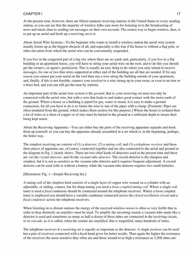
The simplest receiving set consists of (1) a detector, (2) a tuning coil, and (3) a telephone receiver and thesethree pieces of apparatus are, of course, connected together and are also connected to the aerial and ground asthe diagram in Fig. 1 clearly shows. There are two chief kinds of detectors used at the present time and theseare: (a) the crystal detector, and (b) the vacuum tube detector. The crystal detector is the cheapest andsimplest, but it is not as sensitive as the vacuum tube detector and it requires frequent adjustment. A crystaldetector can be used with or without a battery while the vacuum tube detector requires two small batteries.
[Illustration: Fig. 1.--Simple Receiving Set.]
A tuning coil of the simplest kind consists of a single layer of copper wire wound on a cylinder with anadjustable, or sliding, contact, but for sharp tuning you need a loose coupled tuning coil. Where a single coiltuner is used a fixed condenser should be connected around the telephone receivers. Where a loose coupledtuner is employed you should have a variable condenser connected across the closed oscillation circuit and afixed condenser across the telephone receivers.
When listening-in to distant stations the energy of the received wireless waves is often so very feeble that inorder to hear distinctly an amplifier must be used. To amplify the incoming sounds a vacuum tube made like adetector is used and sometimes as many as half-a-dozen of these tubes are connected in the receiving circuit,or in cascade, as it is called, when the sounds are amplified, that is magnified, many hundreds of times.
The telephone receiver of a receiving set is equally as important as the detector. A single receiver can be usedbut a pair of receivers connected with a head-band gives far better results. Then again the higher the resistanceof the receivers the more sensitive they often are and those wound to as high a resistance as 3,200 ohms are
CHAPTER I 17
made for use with the best sets. To make the incoming signals, conversation or music, audible to a room fullof people instead of to just yourself you must use what is called a loud speaker. In its simplest form thisconsists of a metal cone like a megaphone to which is fitted a telephone receiver.
About Transmitting Stations--Getting Your License.--If you are going to install a wireless sending apparatus,either telegraphic or telephonic, you will have to secure a government license for which no fee or charge ofany kind is made. There are three classes of licenses issued to amateurs who want to operate transmittingstations and these are: (1) the restricted amateur license, (2) the general amateur license, and (3) the specialamateur license.
If you are going to set up a transmitter within five nautical miles of any naval wireless station then you willhave to get a restricted amateur license which limits the current you use to half a kilowatt [Footnote: AKilowatt is 1,000 watts. There are 746 watts in a horsepower.] and the wave length you send out to 200meters. Should you live outside of the five-mile range of a navy station then you can get a general amateurlicense and this permits you to use a current of 1 kilowatt, but you are likewise limited to a wave length of 200meters. But if you can show that you are doing some special kind of wireless work and not using your sendingstation for the mere pleasure you are getting out of it you may be able to get a special amateur license whichgives you the right to send out wave lengths up to 375 meters.
When you are ready to apply for your license write to the Radio Inspector of whichever one of the followingdistricts you live in:
First District..............Boston, Mass. Second " ..............New York City Third " ..............Baltimore, Md. Fourth" ..............Norfolk, Va. Fifth " ..............New Orleans, La. Sixth " ............. San Francisco, Cal. Seventh "............. Seattle, Wash. Eighth " ............. Detroit, Mich. Ninth " ..............Chicago, Ill.
Kinds of Transmitters.--There are two general types of transmitters used for sending out wireless messagesand these are: (1) wireless telegraph transmitters, and (2) wireless telephone transmitters. Telegraphtransmitters may use either: (a) a _jump-spark_, (b) an electric arc, or (c) a vacuum tube apparatus for sendingout dot and dash messages, while telephone transmitters may use either, (a) an electric arc, or (b) a vacuumtube for sending out vocal and musical sounds. Amateurs generally use a _jump-spark_ for sending wirelesstelegraph messages and the vacuum tube for sending wireless telephone messages.
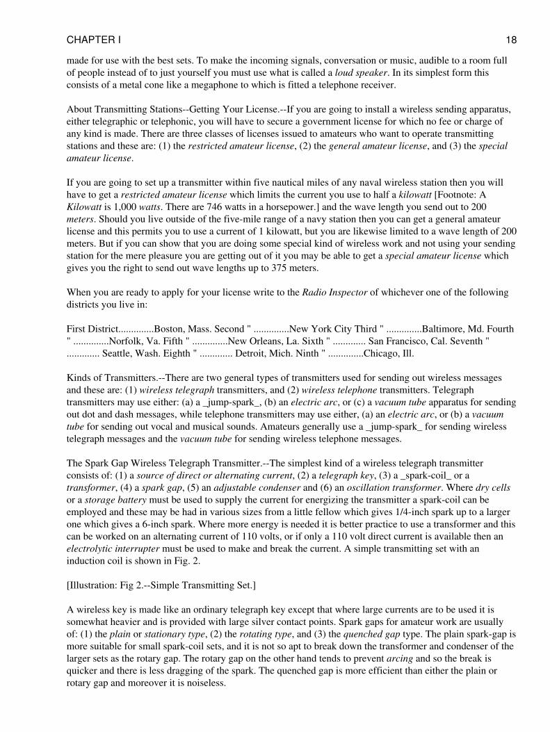
The Spark Gap Wireless Telegraph Transmitter.--The simplest kind of a wireless telegraph transmitterconsists of: (1) a source of direct or alternating current, (2) a telegraph key, (3) a _spark-coil_ or atransformer, (4) a spark gap, (5) an adjustable condenser and (6) an oscillation transformer. Where dry cellsor a storage battery must be used to supply the current for energizing the transmitter a spark-coil can beemployed and these may be had in various sizes from a little fellow which gives 1/4-inch spark up to a largerone which gives a 6-inch spark. Where more energy is needed it is better practice to use a transformer and thiscan be worked on an alternating current of 110 volts, or if only a 110 volt direct current is available then anelectrolytic interrupter must be used to make and break the current. A simple transmitting set with aninduction coil is shown in Fig. 2.
[Illustration: Fig 2.--Simple Transmitting Set.]
A wireless key is made like an ordinary telegraph key except that where large currents are to be used it issomewhat heavier and is provided with large silver contact points. Spark gaps for amateur work are usuallyof: (1) the plain or stationary type, (2) the rotating type, and (3) the quenched gap type. The plain spark-gap ismore suitable for small spark-coil sets, and it is not so apt to break down the transformer and condenser of thelarger sets as the rotary gap. The rotary gap on the other hand tends to prevent arcing and so the break isquicker and there is less dragging of the spark. The quenched gap is more efficient than either the plain orrotary gap and moreover it is noiseless.
CHAPTER I 18
Condensers for spark telegraph transmitters can be ordinary Leyden jars or glass plates coated with tin orcopper foil and set into a frame, or they can be built up of mica and sheet metal embedded in an insulatingcomposition. The glass plate condensers are the cheapest and will serve your purpose well, especially if theyare immersed in oil. Tuning coils, sometimes called transmitting inductances and oscillation transformers, areof various types. The simplest kind is a transmitting inductance which consists of 25 or 30 turns of copperwire wound on an insulating tube or frame. An oscillation transformer is a loose coupled tuning coil and itconsists of a primary coil formed of a number of turns of copper wire wound on a fixed insulating support,and a secondary coil of about twice the number of turns of copper wire which is likewise fixed in an insulatingsupport, but the coils are relatively movable. An oscillation transformer (instead of a _tuning coil_), isrequired by government regulations unless inductively coupled.
The Vacuum Tube Telegraph Transmitter.--This consists of: (1) a source of direct or alternating current, (2) atelegraph key, (3) a vacuum tube oscillator, (4) a tuning coil, and (5) a condenser. This kind of a transmittersets up sustained oscillations instead of periodic oscillations which are produced by a spark gap set. Theadvantages of this kind of a system will be found explained in Chapter XVI.
The Wireless Telephone Transmitter.--Because a jump-spark sets up periodic oscillations, that is, theoscillations are discontinuous, it cannot be used for wireless telephony. An electric arc or a vacuum tube setsup sustained oscillations, that is, oscillations which are continuous. As it is far easier to keep the oscillationsgoing with a vacuum tube than it is with an arc the former means has all but supplanted the latter for wirelesstelephone transmitters. The apparatus required and the connections used for wireless telephone sets will bedescribed in later chapters.
Useful Information.--It would be wise for the reader to turn to the Appendix, beginning with page 301 of thisbook, and familiarize himself with the information there set down in tabular and graphic form. For example,the first table gives abbreviations of electrical terms which are in general use in all works dealing with thesubject. You will also find there brief definitions of electric and magnetic units, which it would be well tocommit to memory; or, at least, to make so thoroughly your own that when any of these terms is mentioned,you will know instantly what is being talked about.
CHAPTER II
PUTTING UP YOUR AERIAL
As inferred in the first chapter, an aerial for receiving does not have to be nearly as well made or put up as onefor sending. But this does not mean that you can slipshod the construction and installation of it, for howeversimple it is, the job must be done right and in this case it is as easy to do it right as wrong.
To send wireless telegraph and telephone messages to the greatest distances and to receive them as distinctlyas possible from the greatest distances you must use for your aerial (1) copper or aluminum wire, (2) two ormore wires, (3) have them the proper length, (4) have them as high in the air as you can, (5) have them wellapart from each other, and (6) have them well insulated from their supports. If you live in a flat building or anapartment house you can string your aerial wires from one edge of the roof to the other and support them bywooden stays as high above it as may be convenient.
Should you live in a detached house in the city you can usually get your next-door neighbor to let you fastenone end of the aerial to his house and this will give you a good stretch and a fairly high aerial. In the countryyou can stretch your wires between the house and barn or the windmill. From this you will see that no matterwhere you live you can nearly always find ways and means of putting up an aerial that will serve your needswithout going to the expense of erecting a mast.
CHAPTER II 19
Kinds of Aerial Wire Systems.--An amateur wireless aerial can be anywhere from 25 feet to 100 feet long andif you can get a stretch of the latter length and a height of from 30 to 75 feet you will have one with which youcan receive a thousand miles or more and send out as much energy as the government will allow you to send.
The kind of an aerial that gives the best results is one whose wire, or wires, are horizontal, that is, parallelwith the earth under it as shown at A in Fig. 3. If only one end can be fixed to some elevated support then youcan secure the other end to a post in the ground, but the slope of the aerial should not be more than 30 or 35degrees from the horizontal at most as shown at B.
[Illustration: (A) Fig. 3.--Flat top, or Horizontal Aerial.]
[Illustration: (B) Fig. 3.--Inclined Aerial.]
The _leading-in wire_, that is, the wire that leads from and joins the aerial wire with your sending andreceiving set, can be connected to the aerial anywhere it is most convenient to do so, but the best results arehad when it is connected to one end as shown at A in Fig. 4, in which case it is called an inverted L aerial, orwhen it is connected to it at the middle as shown at B, when it is called a T aerial. The leading-in wire mustbe carefully insulated from the outside of the building and also where it passes through it to the inside. This isdone by means of an insulating tube known as a _leading-in insulator_, or bulkhead insulator as it issometimes called.
[Illustration: (A) Fig. 4.--Inverted L Aerial.]
[Illustration: (B) Fig. 4.--T Aerial.]
As a protection against lightning burning out your instruments you can use either: (1) an _air-gap lightningarrester,_ (2) a vacuum tube protector, or (3) a lightning switch, which is better. Whichever of these devices isused it is connected in between the aerial and an outside ground wire so that a direct circuit to the earth will beprovided at all times except when you are sending or receiving. So your aerial instead of being a menacereally acts during an electrical storm like a lightning rod and it is therefore a real protection. The air-gap andvacuum tube lightning arresters are little devices that can be used only where you are going to receive, whilethe lightning switch must be used where you are going to send; indeed, in some localities the FireUnderwriters require a large lightning switch to be used for receiving sets as well as sending sets.
How to Put Up a Cheap Receiving Aerial.--The kind of an aerial wire system you put up will depend, chiefly,on two things, and these are: (1) your pocketbook, and (2) the place where you live.
A Single Wire Aerial.--This is the simplest and cheapest kind of a receiving aerial that can be put up. The firstthing to do is to find out the length of wire you need by measuring the span between the two points of support;then add a sufficient length for the leading-in wire and enough more to connect your receiving set with theradiator or water pipe.
You can use any size of copper or aluminum wire that is not smaller than _No. 16 Brown and Sharpe gauge._When you buy the wire get also the following material: (1) two porcelain insulators as shown at A in Fig. 5;(2) three or four porcelain knob insulators, see B; (3) either (a) an _air gap lightning arrester,_ see C, or (b) alightning switch see D; (4) a _leading-in porcelain tube insulator,_ see E, and (5) a ground clamp, see F.
[Illustration: Fig. 5.--Material for a Simple Aerial Wire System.]
To make the aerial slip each end of the wire through a hole in each insulator and twist it fast; next cut off andslip two more pieces of wire through the other holes in the insulators and twist them fast and then secure theseto the supports at the ends of the building. Take the piece you are going to use for the leading-in wire, twist it
CHAPTER II 20
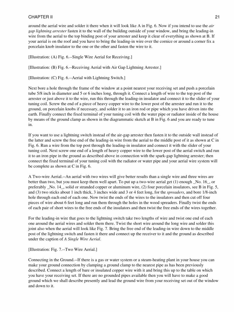
around the aerial wire and solder it there when it will look like A in Fig. 6. Now if you intend to use the airgap lightning arrester fasten it to the wall of the building outside of your window, and bring the leading-inwire from the aerial to the top binding post of your arrester and keep it clear of everything as shown at B. Ifyour aerial is on the roof and you have to bring the leading-in wire over the cornice or around a corner fix aporcelain knob insulator to the one or the other and fasten the wire to it.
[Illustration: (A) Fig. 6.--Single Wire Aerial for Receiving.]
[Illustration: (B) Fig. 6.--Receiving Aerial with Air Gap Lightning Arrester.]
[Illustration: (C) Fig. 6.--Aerial with Lightning Switch.]
Next bore a hole through the frame of the window at a point nearest your receiving set and push a porcelaintube 5/8 inch in diameter and 5 or 6 inches long, through it. Connect a length of wire to the top post of thearrester or just above it to the wire, run this through the leading-in insulator and connect it to the slider of yourtuning coil. Screw the end of a piece of heavy copper wire to the lower post of the arrester and run it to theground, on porcelain knobs if necessary, and solder it to an iron rod or pipe which you have driven into theearth. Finally connect the fixed terminal of your tuning coil with the water pipe or radiator inside of the houseby means of the ground clamp as shown in the diagrammatic sketch at B in Fig. 6 and you are ready to tunein.
If you want to use a lightning switch instead of the air-gap arrester then fasten it to the outside wall instead ofthe latter and screw the free end of the leading-in wire from the aerial to the middle post of it as shown at C inFig. 6. Run a wire from the top post through the leading-in insulator and connect it with the slider of yourtuning coil. Next screw one end of a length of heavy copper wire to the lower post of the aerial switch and runit to an iron pipe in the ground as described above in connection with the spark-gap lightning arrester; thenconnect the fixed terminal of your tuning coil with the radiator or water pipe and your aerial wire system willbe complete as shown at C in Fig. 6.
A Two-wire Aerial.--An aerial with two wires will give better results than a single wire and three wires arebetter than two, but you must keep them well apart. To put up a two-wire aerial get (1) enough _No. 16_, orpreferably _No. 14_, solid or stranded copper or aluminum wire, (2) four porcelain insulators, see B in Fig. 5,and (3) two sticks about 1 inch thick, 3 inches wide and 3 or 4 feet long, for the spreaders, and bore 1/8-inchhole through each end of each one. Now twist the ends of the wires to the insulators and then cut off fourpieces of wire about 6 feet long and run them through the holes in the wood spreaders. Finally twist the endsof each pair of short wires to the free ends of the insulators and then twist the free ends of the wires together.
For the leading-in wire that goes to the lightning switch take two lengths of wire and twist one end of eachone around the aerial wires and solder them there. Twist the short wire around the long wire and solder thisjoint also when the aerial will look like Fig. 7. Bring the free end of the leading-in wire down to the middlepost of the lightning switch and fasten it there and connect up the receiver to it and the ground as describedunder the caption of A Single Wire Aerial.
[Illustration: Fig. 7.--Two Wire Aerial.]
Connecting in the Ground.--If there is a gas or water system or a steam-heating plant in your house you canmake your ground connection by clamping a ground clamp to the nearest pipe as has been previouslydescribed. Connect a length of bare or insulated copper wire with it and bring this up to the table on whichyou have your receiving set. If there are no grounded pipes available then you will have to make a goodground which we shall describe presently and lead the ground wire from your receiving set out of the windowand down to it.
CHAPTER II 21
How to Put Up a Good Aerial.--While you can use the cheap aerial already described for a small spark-coilsending set you should have a better insulated one for a 1/2 or a 1 kilowatt transformer set. The cost for thematerials for a good aerial is small and when properly made and well insulated it will give results that are allout of proportion to the cost of it.
An Inexpensive Good Aerial.--A far better aerial, because it is more highly insulated, can be made by usingmidget insulators instead of the porcelain insulators described under the caption of A Single Wire Aerial andusing a small _electrose leading-in insulator_ instead of the porcelain bushing. This makes a good sendingaerial for small sets as well as a good receiving aerial.
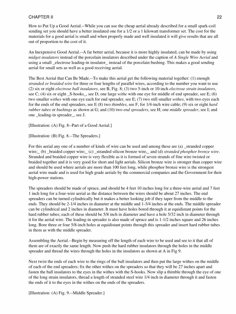
The Best Aerial that Can Be Made.--To make this aerial get the following material together: (1) enoughstranded or braided wire for three or four lengths of parallel wires, according to the number you want to use(2) six or eight electrose ball insulators, see B, Fig. 8; (3) two 5-inch or 10-inch electrose strain insulators,see C; (4) six or eight _S-hooks_, see D; one large withe with one eye for middle of end spreader, see E; (6)two smaller withes with one eye each for end spreader, see E; (7) two still smaller withes, with two eyes eachfor the ends of the end spreaders, see E (8) two thimbles, see F, for 1/4-inch wire cable; (9) six or eight hardrubber tubes or bushings as shown at G; and (10) two end spreaders, see H; one middle spreader, see I; andone _leading-in spreader_, see J.
[Illustration: (A) Fig. 8--Part of a Good Aerial.]
[Illustration: (B) Fig. 8.--The Spreaders.]
For this aerial any one of a number of kinds of wire can be used and among these are (a) _stranded copperwire;_ (b) _braided copper wire;_ (c) _stranded silicon bronze wire,_ and (d) stranded phosphor bronze wire.Stranded and braided copper wire is very flexible as it is formed of seven strands of fine wire twisted orbraided together and it is very good for short and light aerials. Silicon bronze wire is stronger than copper wireand should be used where aerials are more than 100 feet long, while phosphor bronze wire is the strongestaerial wire made and is used for high grade aerials by the commercial companies and the Government for theirhigh-power stations.
The spreaders should be made of spruce, and should be 4 feet 10 inches long for a three-wire aerial and 7 feet1 inch long for a four-wire aerial as the distance between the wires should be about 27 inches. The endspreaders can be turned cylindrically but it makes a better looking job if they taper from the middle to theends. They should be 2-1/4 inches in diameter at the middle and 1-3/4 inches at the ends. The middle spreadercan be cylindrical and 2 inches in diameter. It must have holes bored through it at equidistant points for thehard rubber tubes; each of these should be 5/8 inch in diameter and have a hole 5/32 inch in diameter throughit for the aerial wire. The leading-in spreader is also made of spruce and is 1-1/2 inches square and 26 incheslong. Bore three or four 5/8-inch holes at equidistant points through this spreader and insert hard rubber tubesin them as with the middle spreader.
Assembling the Aerial.--Begin by measuring off the length of each wire to be used and see to it that all ofthem are of exactly the same length. Now push the hard rubber insulators through the holes in the middlespreader and thread the wires through the holes in the insulators as shown at A in Fig 9.
Next twist the ends of each wire to the rings of the ball insulators and then put the large withes on the middleof each of the end spreaders; fix the other withes on the spreaders so that they will be 27 inches apart andfasten the ball insulators to the eyes in the withes with the S-hooks. Now slip a thimble through the eye of oneof the long strain insulators, thread a length of stranded steel wire 1/4 inch in diameter through it and fastenthe ends of it to the eyes in the withes on the ends of the spreaders.
[Illustration: (A) Fig. 9.--Middle Spreader.]
CHAPTER II 22
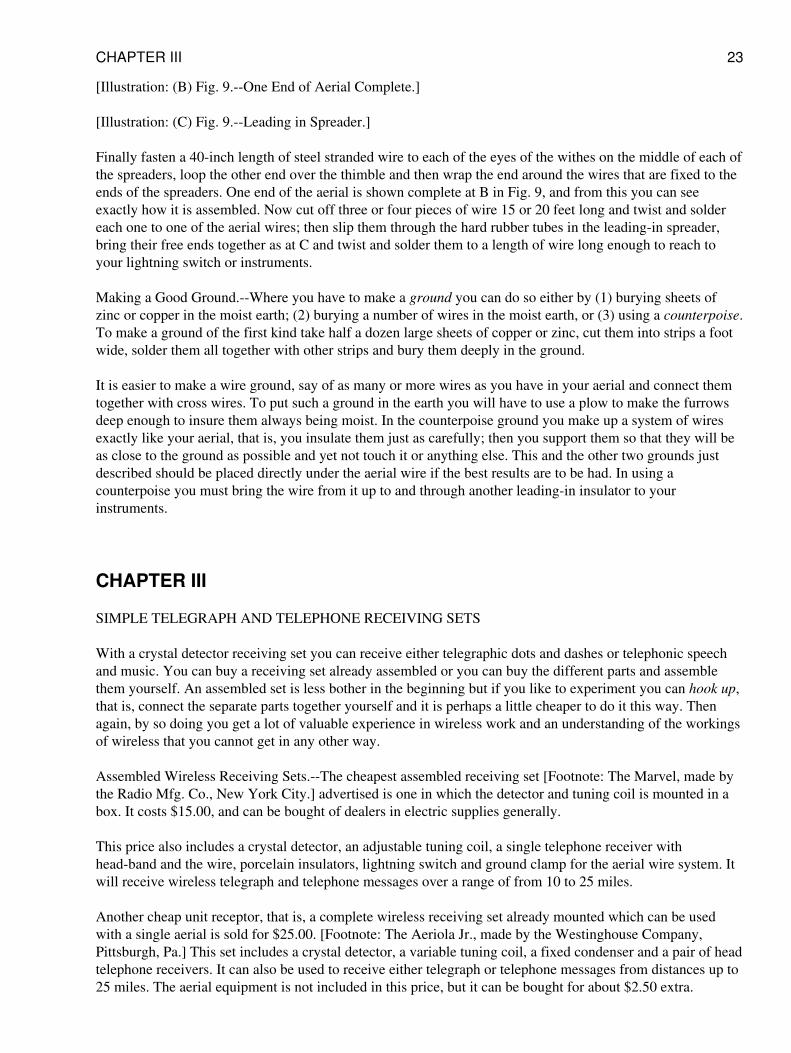
[Illustration: (B) Fig. 9.--One End of Aerial Complete.]
[Illustration: (C) Fig. 9.--Leading in Spreader.]
Finally fasten a 40-inch length of steel stranded wire to each of the eyes of the withes on the middle of each ofthe spreaders, loop the other end over the thimble and then wrap the end around the wires that are fixed to theends of the spreaders. One end of the aerial is shown complete at B in Fig. 9, and from this you can seeexactly how it is assembled. Now cut off three or four pieces of wire 15 or 20 feet long and twist and soldereach one to one of the aerial wires; then slip them through the hard rubber tubes in the leading-in spreader,bring their free ends together as at C and twist and solder them to a length of wire long enough to reach toyour lightning switch or instruments.
Making a Good Ground.--Where you have to make a ground you can do so either by (1) burying sheets ofzinc or copper in the moist earth; (2) burying a number of wires in the moist earth, or (3) using a counterpoise.To make a ground of the first kind take half a dozen large sheets of copper or zinc, cut them into strips a footwide, solder them all together with other strips and bury them deeply in the ground.
It is easier to make a wire ground, say of as many or more wires as you have in your aerial and connect themtogether with cross wires. To put such a ground in the earth you will have to use a plow to make the furrowsdeep enough to insure them always being moist. In the counterpoise ground you make up a system of wiresexactly like your aerial, that is, you insulate them just as carefully; then you support them so that they will beas close to the ground as possible and yet not touch it or anything else. This and the other two grounds justdescribed should be placed directly under the aerial wire if the best results are to be had. In using acounterpoise you must bring the wire from it up to and through another leading-in insulator to yourinstruments.
CHAPTER III
SIMPLE TELEGRAPH AND TELEPHONE RECEIVING SETS
With a crystal detector receiving set you can receive either telegraphic dots and dashes or telephonic speechand music. You can buy a receiving set already assembled or you can buy the different parts and assemblethem yourself. An assembled set is less bother in the beginning but if you like to experiment you can hook up,that is, connect the separate parts together yourself and it is perhaps a little cheaper to do it this way. Thenagain, by so doing you get a lot of valuable experience in wireless work and an understanding of the workingsof wireless that you cannot get in any other way.
Assembled Wireless Receiving Sets.--The cheapest assembled receiving set [Footnote: The Marvel, made bythe Radio Mfg. Co., New York City.] advertised is one in which the detector and tuning coil is mounted in abox. It costs $15.00, and can be bought of dealers in electric supplies generally.
This price also includes a crystal detector, an adjustable tuning coil, a single telephone receiver withhead-band and the wire, porcelain insulators, lightning switch and ground clamp for the aerial wire system. Itwill receive wireless telegraph and telephone messages over a range of from 10 to 25 miles.
Another cheap unit receptor, that is, a complete wireless receiving set already mounted which can be usedwith a single aerial is sold for $25.00. [Footnote: The Aeriola Jr., made by the Westinghouse Company,Pittsburgh, Pa.] This set includes a crystal detector, a variable tuning coil, a fixed condenser and a pair of headtelephone receivers. It can also be used to receive either telegraph or telephone messages from distances up to25 miles. The aerial equipment is not included in this price, but it can be bought for about $2.50 extra.
CHAPTER III 23
Assembling Your Own Receiving Set.--In this chapter we shall go only into the apparatus used for two simplereceiving sets, both of which have a crystal detector. The first set includes a _double-slide tuning coil_ andthe second set employs a _loose-coupled tuning coil_, or loose coupler, as it is called for short. For either setyou can use a pair of 2,000- or 3,000-ohm head phones.
[Illustration: original © Underwood and Underwood. General Pershing Listening In.]
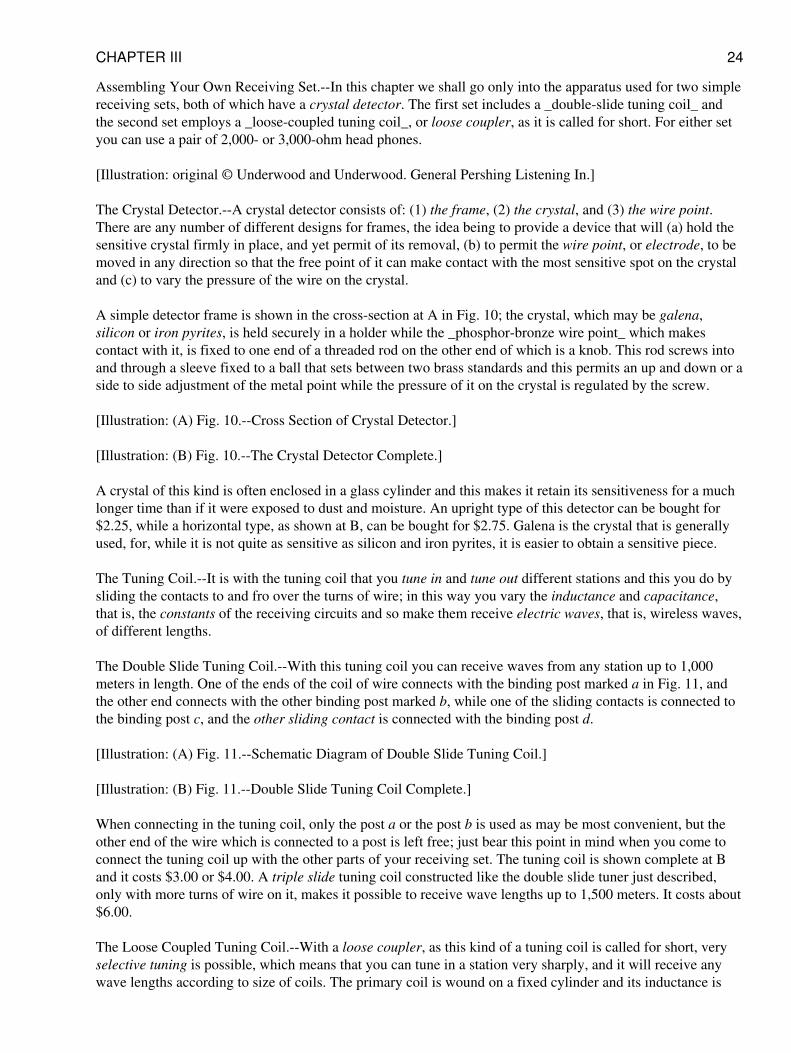
The Crystal Detector.--A crystal detector consists of: (1) the frame, (2) the crystal, and (3) the wire point.There are any number of different designs for frames, the idea being to provide a device that will (a) hold thesensitive crystal firmly in place, and yet permit of its removal, (b) to permit the wire point, or electrode, to bemoved in any direction so that the free point of it can make contact with the most sensitive spot on the crystaland (c) to vary the pressure of the wire on the crystal.
A simple detector frame is shown in the cross-section at A in Fig. 10; the crystal, which may be galena,silicon or iron pyrites, is held securely in a holder while the _phosphor-bronze wire point_ which makescontact with it, is fixed to one end of a threaded rod on the other end of which is a knob. This rod screws intoand through a sleeve fixed to a ball that sets between two brass standards and this permits an up and down or aside to side adjustment of the metal point while the pressure of it on the crystal is regulated by the screw.
[Illustration: (A) Fig. 10.--Cross Section of Crystal Detector.]
[Illustration: (B) Fig. 10.--The Crystal Detector Complete.]
A crystal of this kind is often enclosed in a glass cylinder and this makes it retain its sensitiveness for a muchlonger time than if it were exposed to dust and moisture. An upright type of this detector can be bought for$2.25, while a horizontal type, as shown at B, can be bought for $2.75. Galena is the crystal that is generallyused, for, while it is not quite as sensitive as silicon and iron pyrites, it is easier to obtain a sensitive piece.
The Tuning Coil.--It is with the tuning coil that you tune in and tune out different stations and this you do bysliding the contacts to and fro over the turns of wire; in this way you vary the inductance and capacitance,that is, the constants of the receiving circuits and so make them receive electric waves, that is, wireless waves,of different lengths.
The Double Slide Tuning Coil.--With this tuning coil you can receive waves from any station up to 1,000meters in length. One of the ends of the coil of wire connects with the binding post marked a in Fig. 11, andthe other end connects with the other binding post marked b, while one of the sliding contacts is connected tothe binding post c, and the other sliding contact is connected with the binding post d.
[Illustration: (A) Fig. 11.--Schematic Diagram of Double Slide Tuning Coil.]
[Illustration: (B) Fig. 11.--Double Slide Tuning Coil Complete.]
When connecting in the tuning coil, only the post a or the post b is used as may be most convenient, but theother end of the wire which is connected to a post is left free; just bear this point in mind when you come toconnect the tuning coil up with the other parts of your receiving set. The tuning coil is shown complete at Band it costs $3.00 or $4.00. A triple slide tuning coil constructed like the double slide tuner just described,only with more turns of wire on it, makes it possible to receive wave lengths up to 1,500 meters. It costs about$6.00.
The Loose Coupled Tuning Coil.--With a loose coupler, as this kind of a tuning coil is called for short, veryselective tuning is possible, which means that you can tune in a station very sharply, and it will receive anywave lengths according to size of coils. The primary coil is wound on a fixed cylinder and its inductance is
CHAPTER III 24
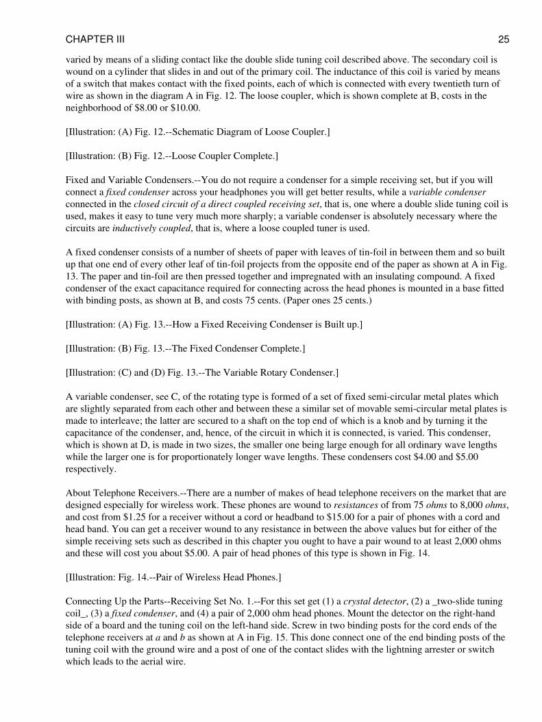
varied by means of a sliding contact like the double slide tuning coil described above. The secondary coil iswound on a cylinder that slides in and out of the primary coil. The inductance of this coil is varied by meansof a switch that makes contact with the fixed points, each of which is connected with every twentieth turn ofwire as shown in the diagram A in Fig. 12. The loose coupler, which is shown complete at B, costs in theneighborhood of $8.00 or $10.00.
[Illustration: (A) Fig. 12.--Schematic Diagram of Loose Coupler.]
[Illustration: (B) Fig. 12.--Loose Coupler Complete.]
Fixed and Variable Condensers.--You do not require a condenser for a simple receiving set, but if you willconnect a fixed condenser across your headphones you will get better results, while a variable condenserconnected in the closed circuit of a direct coupled receiving set, that is, one where a double slide tuning coil isused, makes it easy to tune very much more sharply; a variable condenser is absolutely necessary where thecircuits are inductively coupled, that is, where a loose coupled tuner is used.
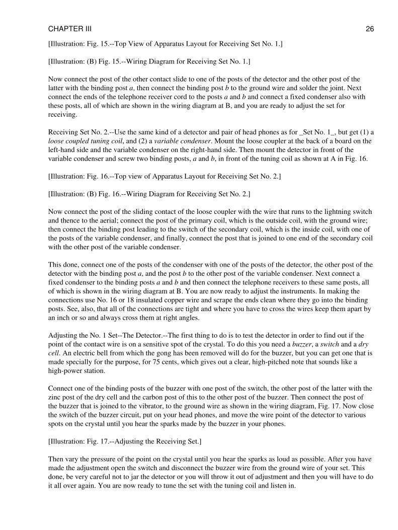
A fixed condenser consists of a number of sheets of paper with leaves of tin-foil in between them and so builtup that one end of every other leaf of tin-foil projects from the opposite end of the paper as shown at A in Fig.13. The paper and tin-foil are then pressed together and impregnated with an insulating compound. A fixedcondenser of the exact capacitance required for connecting across the head phones is mounted in a base fittedwith binding posts, as shown at B, and costs 75 cents. (Paper ones 25 cents.)
[Illustration: (A) Fig. 13.--How a Fixed Receiving Condenser is Built up.]
[Illustration: (B) Fig. 13.--The Fixed Condenser Complete.]
[Illustration: (C) and (D) Fig. 13.--The Variable Rotary Condenser.]
A variable condenser, see C, of the rotating type is formed of a set of fixed semi-circular metal plates whichare slightly separated from each other and between these a similar set of movable semi-circular metal plates ismade to interleave; the latter are secured to a shaft on the top end of which is a knob and by turning it thecapacitance of the condenser, and, hence, of the circuit in which it is connected, is varied. This condenser,which is shown at D, is made in two sizes, the smaller one being large enough for all ordinary wave lengthswhile the larger one is for proportionately longer wave lengths. These condensers cost $4.00 and $5.00respectively.
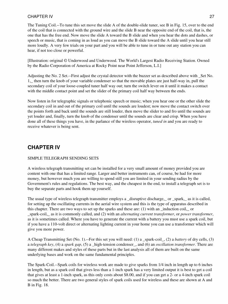
About Telephone Receivers.--There are a number of makes of head telephone receivers on the market that aredesigned especially for wireless work. These phones are wound to resistances of from 75 ohms to 8,000 ohms,and cost from $1.25 for a receiver without a cord or headband to $15.00 for a pair of phones with a cord andhead band. You can get a receiver wound to any resistance in between the above values but for either of thesimple receiving sets such as described in this chapter you ought to have a pair wound to at least 2,000 ohmsand these will cost you about $5.00. A pair of head phones of this type is shown in Fig. 14.
[Illustration: Fig. 14.--Pair of Wireless Head Phones.]
Connecting Up the Parts--Receiving Set No. 1.--For this set get (1) a crystal detector, (2) a _two-slide tuningcoil_, (3) a fixed condenser, and (4) a pair of 2,000 ohm head phones. Mount the detector on the right-handside of a board and the tuning coil on the left-hand side. Screw in two binding posts for the cord ends of thetelephone receivers at a and b as shown at A in Fig. 15. This done connect one of the end binding posts of thetuning coil with the ground wire and a post of one of the contact slides with the lightning arrester or switchwhich leads to the aerial wire.
CHAPTER III 25
[Illustration: Fig. 15.--Top View of Apparatus Layout for Receiving Set No. 1.]
[Illustration: (B) Fig. 15.--Wiring Diagram for Receiving Set No. 1.]
Now connect the post of the other contact slide to one of the posts of the detector and the other post of thelatter with the binding post a, then connect the binding post b to the ground wire and solder the joint. Nextconnect the ends of the telephone receiver cord to the posts a and b and connect a fixed condenser also withthese posts, all of which are shown in the wiring diagram at B, and you are ready to adjust the set forreceiving.
Receiving Set No. 2.--Use the same kind of a detector and pair of head phones as for _Set No. 1_, but get (1) aloose coupled tuning coil, and (2) a variable condenser. Mount the loose coupler at the back of a board on theleft-hand side and the variable condenser on the right-hand side. Then mount the detector in front of thevariable condenser and screw two binding posts, a and b, in front of the tuning coil as shown at A in Fig. 16.
[Illustration: Fig. 16.--Top view of Apparatus Layout for Receiving Set No. 2.]
[Illustration: (B) Fig. 16.--Wiring Diagram for Receiving Set No. 2.]
Now connect the post of the sliding contact of the loose coupler with the wire that runs to the lightning switchand thence to the aerial; connect the post of the primary coil, which is the outside coil, with the ground wire;then connect the binding post leading to the switch of the secondary coil, which is the inside coil, with one ofthe posts of the variable condenser, and finally, connect the post that is joined to one end of the secondary coilwith the other post of the variable condenser.
This done, connect one of the posts of the condenser with one of the posts of the detector, the other post of thedetector with the binding post a, and the post b to the other post of the variable condenser. Next connect afixed condenser to the binding posts a and b and then connect the telephone receivers to these same posts, allof which is shown in the wiring diagram at B. You are now ready to adjust the instruments. In making theconnections use No. 16 or 18 insulated copper wire and scrape the ends clean where they go into the bindingposts. See, also, that all of the connections are tight and where you have to cross the wires keep them apart byan inch or so and always cross them at right angles.
Adjusting the No. 1 Set--The Detector.--The first thing to do is to test the detector in order to find out if thepoint of the contact wire is on a sensitive spot of the crystal. To do this you need a buzzer, a switch and a drycell. An electric bell from which the gong has been removed will do for the buzzer, but you can get one that ismade specially for the purpose, for 75 cents, which gives out a clear, high-pitched note that sounds like ahigh-power station.
Connect one of the binding posts of the buzzer with one post of the switch, the other post of the latter with thezinc post of the dry cell and the carbon post of this to the other post of the buzzer. Then connect the post ofthe buzzer that is joined to the vibrator, to the ground wire as shown in the wiring diagram, Fig. 17. Now closethe switch of the buzzer circuit, put on your head phones, and move the wire point of the detector to variousspots on the crystal until you hear the sparks made by the buzzer in your phones.
[Illustration: Fig. 17.--Adjusting the Receiving Set.]
Then vary the pressure of the point on the crystal until you hear the sparks as loud as possible. After you havemade the adjustment open the switch and disconnect the buzzer wire from the ground wire of your set. Thisdone, be very careful not to jar the detector or you will throw it out of adjustment and then you will have to doit all over again. You are now ready to tune the set with the tuning coil and listen in.
CHAPTER III 26
The Tuning Coil.--To tune this set move the slide A of the double-slide tuner, see B in Fig. 15, over to the endof the coil that is connected with the ground wire and the slide B near the opposite end of the coil, that is, theone that has the free end. Now move the slide A toward the B slide and when you hear the dots and dashes, orspeech or music, that is coming in as loud as you can move the B slide toward the A slide until you hear stillmore loudly. A very few trials on your part and you will be able to tune in or tune out any station you canhear, if not too close or powerful.
[Illustration: original © Underwood and Underwood. The World's Largest Radio Receiving Station. Ownedby the Radio Corporation of America at Rocky Point near Point Jefferson, L.I.]
Adjusting the No. 2 Set.--First adjust the crystal detector with the buzzer set as described above with _Set No.1,_ then turn the knob of your variable condenser so that the movable plates are just half-way in, pull thesecondary coil of your loose-coupled tuner half way out; turn the switch lever on it until it makes a contactwith the middle contact point and set the slider of the primary coil half way between the ends.
Now listen in for telegraphic signals or telephonic speech or music; when you hear one or the other slide thesecondary coil in and out of the primary coil until the sounds are loudest; now move the contact switch overthe points forth and back until the sounds are still louder, then move the slider to and fro until the sounds areyet louder and, finally, turn the knob of the condenser until the sounds are clear and crisp. When you havedone all of these things you have, in the parlance of the wireless operator, tuned in and you are ready toreceive whatever is being sent.
CHAPTER IV
SIMPLE TELEGRAPH SENDING SETS
A wireless telegraph transmitting set can be installed for a very small amount of money provided you arecontent with one that has a limited range. Larger and better instruments can, of course, be had for moremoney, but however much you are willing to spend still you are limited in your sending radius by theGovernment's rules and regulations. The best way, and the cheapest in the end, to install a telegraph set is tobuy the separate parts and hook them up yourself.
The usual type of wireless telegraph transmitter employs a _disruptive discharge,_ or _spark,_ as it is called,for setting up the oscillating currents in the aerial wire system and this is the type of apparatus described inthis chapter. There are two ways to set up the sparks and these are: (1) with an _induction coil,_ or_spark-coil,_ as it is commonly called, and (2) with an alternating current transformer, or power transformer,as it is sometimes called. Where you have to generate the current with a battery you must use a spark coil, butif you have a 110-volt direct or alternating lighting current in your home you can use a transformer which willgive you more power.
A Cheap Transmitting Set (No. 1).--For this set you will need: (1) a _spark-coil_, (2) a battery of dry cells, (3)a telegraph key, (4) a spark gap, (5) a _high-tension condenser_, and (6) an oscillation transformer. There aremany different makes and styles of these parts but in the last analysis all of them are built on the sameunderlying bases and work on the same fundamental principles.
The Spark-Coil.--Spark coils for wireless work are made to give sparks from 1/4 inch in length up to 6 inchesin length, but as a spark coil that gives less than a 1-inch spark has a very limited output it is best to get a coilthat gives at least a 1-inch spark, as this only costs about $8.00, and if you can get a 2- or a 4-inch spark coilso much the better. There are two general styles of spark coils used for wireless and these are shown at A andB in Fig. 18.
CHAPTER IV 27
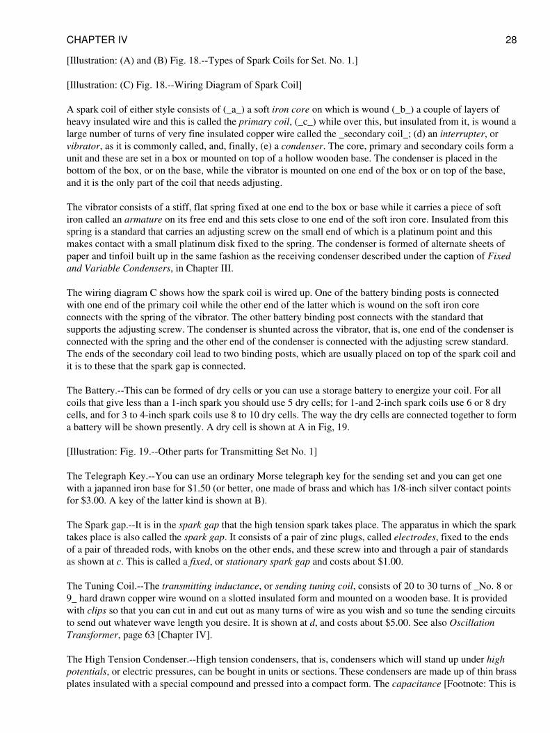
[Illustration: (A) and (B) Fig. 18.--Types of Spark Coils for Set. No. 1.]
[Illustration: (C) Fig. 18.--Wiring Diagram of Spark Coil]
A spark coil of either style consists of (_a_) a soft iron core on which is wound (_b_) a couple of layers ofheavy insulated wire and this is called the primary coil, (_c_) while over this, but insulated from it, is wound alarge number of turns of very fine insulated copper wire called the _secondary coil_; (d) an interrupter, orvibrator, as it is commonly called, and, finally, (e) a condenser. The core, primary and secondary coils form aunit and these are set in a box or mounted on top of a hollow wooden base. The condenser is placed in thebottom of the box, or on the base, while the vibrator is mounted on one end of the box or on top of the base,and it is the only part of the coil that needs adjusting.
The vibrator consists of a stiff, flat spring fixed at one end to the box or base while it carries a piece of softiron called an armature on its free end and this sets close to one end of the soft iron core. Insulated from thisspring is a standard that carries an adjusting screw on the small end of which is a platinum point and thismakes contact with a small platinum disk fixed to the spring. The condenser is formed of alternate sheets ofpaper and tinfoil built up in the same fashion as the receiving condenser described under the caption of Fixedand Variable Condensers, in Chapter III.
The wiring diagram C shows how the spark coil is wired up. One of the battery binding posts is connectedwith one end of the primary coil while the other end of the latter which is wound on the soft iron coreconnects with the spring of the vibrator. The other battery binding post connects with the standard thatsupports the adjusting screw. The condenser is shunted across the vibrator, that is, one end of the condenser isconnected with the spring and the other end of the condenser is connected with the adjusting screw standard.The ends of the secondary coil lead to two binding posts, which are usually placed on top of the spark coil andit is to these that the spark gap is connected.
The Battery.--This can be formed of dry cells or you can use a storage battery to energize your coil. For allcoils that give less than a 1-inch spark you should use 5 dry cells; for 1-and 2-inch spark coils use 6 or 8 drycells, and for 3 to 4-inch spark coils use 8 to 10 dry cells. The way the dry cells are connected together to forma battery will be shown presently. A dry cell is shown at A in Fig, 19.
[Illustration: Fig. 19.--Other parts for Transmitting Set No. 1]
The Telegraph Key.--You can use an ordinary Morse telegraph key for the sending set and you can get onewith a japanned iron base for $1.50 (or better, one made of brass and which has 1/8-inch silver contact pointsfor $3.00. A key of the latter kind is shown at B).
The Spark gap.--It is in the spark gap that the high tension spark takes place. The apparatus in which the sparktakes place is also called the spark gap. It consists of a pair of zinc plugs, called electrodes, fixed to the endsof a pair of threaded rods, with knobs on the other ends, and these screw into and through a pair of standardsas shown at c. This is called a fixed, or stationary spark gap and costs about $1.00.
The Tuning Coil.--The transmitting inductance, or sending tuning coil, consists of 20 to 30 turns of _No. 8 or9_ hard drawn copper wire wound on a slotted insulated form and mounted on a wooden base. It is providedwith clips so that you can cut in and cut out as many turns of wire as you wish and so tune the sending circuitsto send out whatever wave length you desire. It is shown at d, and costs about $5.00. See also OscillationTransformer, page 63 [Chapter IV].
The High Tension Condenser.--High tension condensers, that is, condensers which will stand up under highpotentials, or electric pressures, can be bought in units or sections. These condensers are made up of thin brassplates insulated with a special compound and pressed into a compact form. The capacitance [Footnote: This is
CHAPTER IV 28
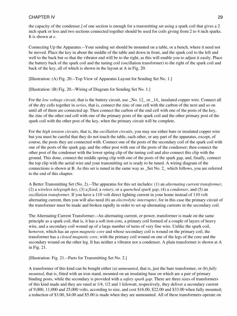
the capacity of the condenser.] of one section is enough for a transmitting set using a spark coil that gives a 2inch spark or less and two sections connected together should be used for coils giving from 2 to 4 inch sparks.It is shown at e.
Connecting Up the Apparatus.--Your sending set should be mounted on a table, or a bench, where it need notbe moved. Place the key in about the middle of the table and down in front, and the spark coil to the left andwell to the back but so that the vibrator end will be to the right, as this will enable you to adjust it easily. Placethe battery back of the spark coil and the tuning coil (oscillation transformer) to the right of the spark coil andback of the key, all of which is shown in the layout at A in Fig. 20.
[Illustration: (A) Fig. 20.--Top View of Apparatus Layout for Sending Set No. 1.]
[Illustration: (B) Fig. 20.--Wiring of Diagram for Sending Set No. 1.]
For the low voltage circuit, that is the battery circuit, use _No. 12_ or _14_ insulated copper wire. Connect allof the dry cells together in series, that is, connect the zinc of one cell with the carbon of the next and so onuntil all of them are connected up. Then connect the carbon of the end cell with one of the posts of the key,the zinc of the other end cell with one of the primary posts of the spark coil and the other primary post of thespark coil with the other post of the key, when the primary circuit will be complete.
For the high tension circuits, that is, the oscillation circuits, you may use either bare or insulated copper wirebut you must be careful that they do not touch the table, each other, or any part of the apparatus, except, ofcourse, the posts they are connected with. Connect one of the posts of the secondary coil of the spark coil withone of the posts of the spark gap, and the other post with one of the posts of the condenser; then connect theother post of the condenser with the lower spring clip of the tuning coil and also connect this clip with theground. This done, connect the middle spring clip with one of the posts of the spark gap, and, finally, connectthe top clip with the aerial wire and your transmitting set is ready to be tuned. A wiring diagram of theconnections is shown at B. As this set is tuned in the same way as _Set No. 2_ which follows, you are referredto the end of this chapter.
A Better Transmitting Set (No. 2).--The apparatus for this set includes: (1) an alternating current transformer,(2) a wireless telegraph key, (3) a fixed, a rotary, or a quenched spark gap, (4) a condenser, and (5) anoscillation transformer. If you have a 110 volt direct lighting current in your home instead of 110 voltalternating current, then you will also need (6) an electrolytic interrupter, for in this case the primary circuit ofthe transformer must be made and broken rapidly in order to set up alternating currents in the secondary coil.
The Alternating Current Transformer.--An alternating current, or power, transformer is made on the sameprinciple as a spark coil, that is, it has a soft iron core, a primary coil formed of a couple of layers of heavywire, and a secondary coil wound up of a large number of turns of very fine wire. Unlike the spark coil,however, which has an open magnetic core and whose secondary coil is wound on the primary coil, thetransformer has a closed magnetic core, with the primary coil wound on one of the legs of the core and thesecondary wound on the other leg. It has neither a vibrator nor a condenser. A plain transformer is shown at Ain Fig. 21.
[Illustration: Fig. 21.--Parts for Transmitting Set No. 2.]
A transformer of this kind can be bought either (a) unmounted, that is, just the bare transformer, or (b) fullymounted, that is, fitted with an iron stand, mounted on an insulating base on which are a pair of primarybinding posts, while the secondary is provided with a safety spark gap. There are three sizes of transformersof this kind made and they are rated at 1/4, 1/2 and 1 kilowatt, respectively, they deliver a secondary currentof 9,000, 11,000 and 25,000 volts, according to size, and cost $16.00, $22.00 and $33.00 when fully mounted;a reduction of $3.00, $4.00 and $5.00 is made when they are unmounted. All of these transformers operate on
CHAPTER IV 29
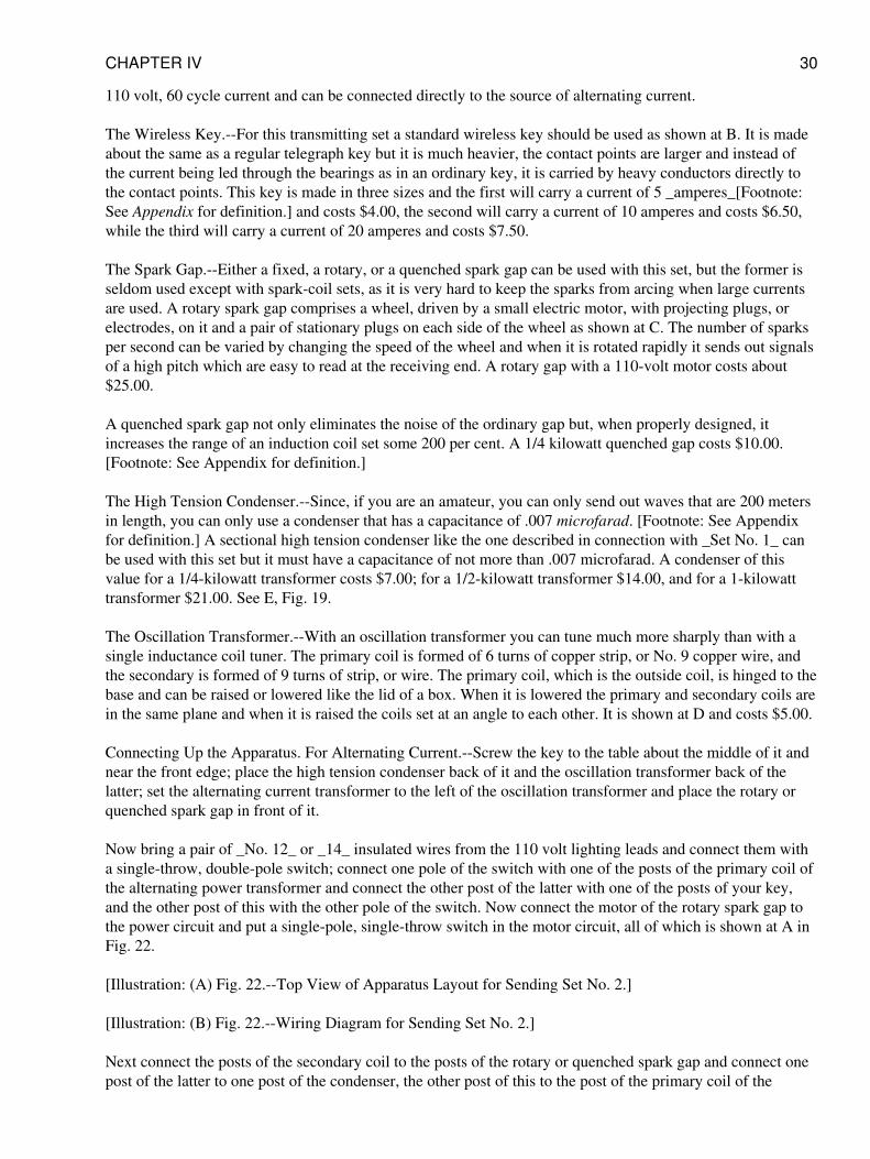
110 volt, 60 cycle current and can be connected directly to the source of alternating current.
The Wireless Key.--For this transmitting set a standard wireless key should be used as shown at B. It is madeabout the same as a regular telegraph key but it is much heavier, the contact points are larger and instead ofthe current being led through the bearings as in an ordinary key, it is carried by heavy conductors directly tothe contact points. This key is made in three sizes and the first will carry a current of 5 _amperes_[Footnote:See Appendix for definition.] and costs $4.00, the second will carry a current of 10 amperes and costs $6.50,while the third will carry a current of 20 amperes and costs $7.50.
The Spark Gap.--Either a fixed, a rotary, or a quenched spark gap can be used with this set, but the former isseldom used except with spark-coil sets, as it is very hard to keep the sparks from arcing when large currentsare used. A rotary spark gap comprises a wheel, driven by a small electric motor, with projecting plugs, orelectrodes, on it and a pair of stationary plugs on each side of the wheel as shown at C. The number of sparksper second can be varied by changing the speed of the wheel and when it is rotated rapidly it sends out signalsof a high pitch which are easy to read at the receiving end. A rotary gap with a 110-volt motor costs about$25.00.
A quenched spark gap not only eliminates the noise of the ordinary gap but, when properly designed, itincreases the range of an induction coil set some 200 per cent. A 1/4 kilowatt quenched gap costs $10.00.[Footnote: See Appendix for definition.]
The High Tension Condenser.--Since, if you are an amateur, you can only send out waves that are 200 metersin length, you can only use a condenser that has a capacitance of .007 microfarad. [Footnote: See Appendixfor definition.] A sectional high tension condenser like the one described in connection with _Set No. 1_ canbe used with this set but it must have a capacitance of not more than .007 microfarad. A condenser of thisvalue for a 1/4-kilowatt transformer costs $7.00; for a 1/2-kilowatt transformer $14.00, and for a 1-kilowatttransformer $21.00. See E, Fig. 19.
The Oscillation Transformer.--With an oscillation transformer you can tune much more sharply than with asingle inductance coil tuner. The primary coil is formed of 6 turns of copper strip, or No. 9 copper wire, andthe secondary is formed of 9 turns of strip, or wire. The primary coil, which is the outside coil, is hinged to thebase and can be raised or lowered like the lid of a box. When it is lowered the primary and secondary coils arein the same plane and when it is raised the coils set at an angle to each other. It is shown at D and costs $5.00.
Connecting Up the Apparatus. For Alternating Current.--Screw the key to the table about the middle of it andnear the front edge; place the high tension condenser back of it and the oscillation transformer back of thelatter; set the alternating current transformer to the left of the oscillation transformer and place the rotary orquenched spark gap in front of it.
Now bring a pair of _No. 12_ or _14_ insulated wires from the 110 volt lighting leads and connect them witha single-throw, double-pole switch; connect one pole of the switch with one of the posts of the primary coil ofthe alternating power transformer and connect the other post of the latter with one of the posts of your key,and the other post of this with the other pole of the switch. Now connect the motor of the rotary spark gap tothe power circuit and put a single-pole, single-throw switch in the motor circuit, all of which is shown at A inFig. 22.
[Illustration: (A) Fig. 22.--Top View of Apparatus Layout for Sending Set No. 2.]
[Illustration: (B) Fig. 22.--Wiring Diagram for Sending Set No. 2.]
Next connect the posts of the secondary coil to the posts of the rotary or quenched spark gap and connect onepost of the latter to one post of the condenser, the other post of this to the post of the primary coil of the
CHAPTER IV 30
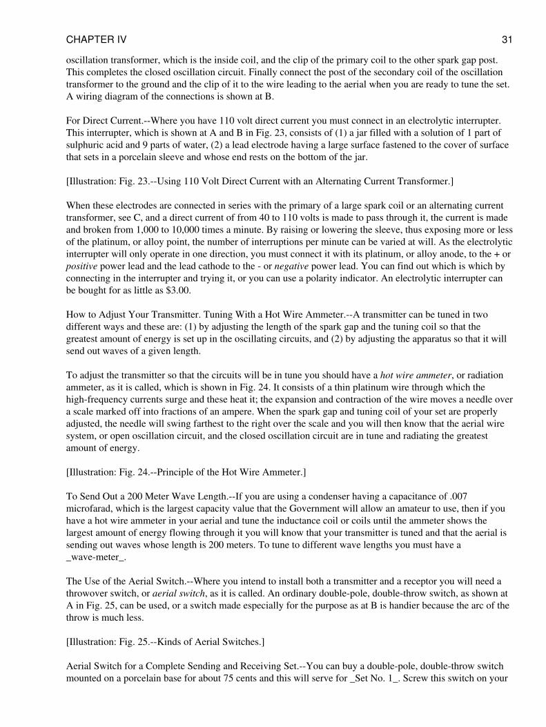
oscillation transformer, which is the inside coil, and the clip of the primary coil to the other spark gap post.This completes the closed oscillation circuit. Finally connect the post of the secondary coil of the oscillationtransformer to the ground and the clip of it to the wire leading to the aerial when you are ready to tune the set.A wiring diagram of the connections is shown at B.
For Direct Current.--Where you have 110 volt direct current you must connect in an electrolytic interrupter.This interrupter, which is shown at A and B in Fig. 23, consists of (1) a jar filled with a solution of 1 part ofsulphuric acid and 9 parts of water, (2) a lead electrode having a large surface fastened to the cover of surfacethat sets in a porcelain sleeve and whose end rests on the bottom of the jar.
[Illustration: Fig. 23.--Using 110 Volt Direct Current with an Alternating Current Transformer.]
When these electrodes are connected in series with the primary of a large spark coil or an alternating currenttransformer, see C, and a direct current of from 40 to 110 volts is made to pass through it, the current is madeand broken from 1,000 to 10,000 times a minute. By raising or lowering the sleeve, thus exposing more or lessof the platinum, or alloy point, the number of interruptions per minute can be varied at will. As the electrolyticinterrupter will only operate in one direction, you must connect it with its platinum, or alloy anode, to the + orpositive power lead and the lead cathode to the - or negative power lead. You can find out which is which byconnecting in the interrupter and trying it, or you can use a polarity indicator. An electrolytic interrupter canbe bought for as little as $3.00.
How to Adjust Your Transmitter. Tuning With a Hot Wire Ammeter.--A transmitter can be tuned in twodifferent ways and these are: (1) by adjusting the length of the spark gap and the tuning coil so that thegreatest amount of energy is set up in the oscillating circuits, and (2) by adjusting the apparatus so that it willsend out waves of a given length.
To adjust the transmitter so that the circuits will be in tune you should have a hot wire ammeter, or radiationammeter, as it is called, which is shown in Fig. 24. It consists of a thin platinum wire through which thehigh-frequency currents surge and these heat it; the expansion and contraction of the wire moves a needle overa scale marked off into fractions of an ampere. When the spark gap and tuning coil of your set are properlyadjusted, the needle will swing farthest to the right over the scale and you will then know that the aerial wiresystem, or open oscillation circuit, and the closed oscillation circuit are in tune and radiating the greatestamount of energy.
[Illustration: Fig. 24.--Principle of the Hot Wire Ammeter.]
To Send Out a 200 Meter Wave Length.--If you are using a condenser having a capacitance of .007microfarad, which is the largest capacity value that the Government will allow an amateur to use, then if youhave a hot wire ammeter in your aerial and tune the inductance coil or coils until the ammeter shows thelargest amount of energy flowing through it you will know that your transmitter is tuned and that the aerial issending out waves whose length is 200 meters. To tune to different wave lengths you must have a_wave-meter_.
The Use of the Aerial Switch.--Where you intend to install both a transmitter and a receptor you will need athrowover switch, or aerial switch, as it is called. An ordinary double-pole, double-throw switch, as shown atA in Fig. 25, can be used, or a switch made especially for the purpose as at B is handier because the arc of thethrow is much less.
[Illustration: Fig. 25.--Kinds of Aerial Switches.]
Aerial Switch for a Complete Sending and Receiving Set.--You can buy a double-pole, double-throw switchmounted on a porcelain base for about 75 cents and this will serve for _Set No. 1_. Screw this switch on your
CHAPTER IV 31
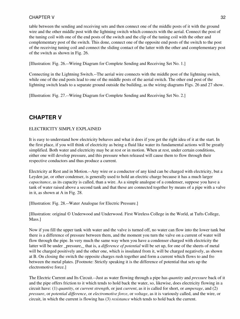
table between the sending and receiving sets and then connect one of the middle posts of it with the groundwire and the other middle post with the lightning switch which connects with the aerial. Connect the post ofthe tuning coil with one of the end posts of the switch and the clip of the tuning coil with the other andcomplementary post of the switch. This done, connect one of the opposite end posts of the switch to the postof the receiving tuning coil and connect the sliding contact of the latter with the other and complementary postof the switch as shown in Fig. 26.
[Illustration: Fig. 26.--Wiring Diagram for Complete Sending and Receiving Set No. 1.]
Connecting in the Lightning Switch.--The aerial wire connects with the middle post of the lightning switch,while one of the end posts lead to one of the middle posts of the aerial switch. The other end post of thelightning switch leads to a separate ground outside the building, as the wiring diagrams Figs. 26 and 27 show.
[Illustration: Fig. 27.--Wiring Diagram for Complete Sending and Receiving Set No. 2.]
CHAPTER V
ELECTRICITY SIMPLY EXPLAINED
It is easy to understand how electricity behaves and what it does if you get the right idea of it at the start. Inthe first place, if you will think of electricity as being a fluid like water its fundamental actions will be greatlysimplified. Both water and electricity may be at rest or in motion. When at rest, under certain conditions,either one will develop pressure, and this pressure when released will cause them to flow through theirrespective conductors and thus produce a current.
Electricity at Rest and in Motion.--Any wire or a conductor of any kind can be charged with electricity, but aLeyden jar, or other condenser, is generally used to hold an electric charge because it has a much largercapacitance, as its capacity is called, than a wire. As a simple analogue of a condenser, suppose you have atank of water raised above a second tank and that these are connected together by means of a pipe with a valvein it, as shown at A in Fig. 28.
[Illustration: Fig. 28.--Water Analogue for Electric Pressure.]
[Illustration: original © Underwood and Underwood. First Wireless College in the World, at Tufts College,Mass.]
Now if you fill the upper tank with water and the valve is turned off, no water can flow into the lower tank butthere is a difference of pressure between them, and the moment you turn the valve on a current of water willflow through the pipe. In very much the same way when you have a condenser charged with electricity thelatter will be under _pressure,_ that is, a difference of potential will be set up, for one of the sheets of metalwill be charged positively and the other one, which is insulated from it, will be charged negatively, as shownat B. On closing the switch the opposite charges rush together and form a current which flows to and frobetween the metal plates. [Footnote: Strictly speaking it is the difference of potential that sets up theelectromotive force.]
The Electric Current and Its Circuit.--Just as water flowing through a pipe has quantity and pressure back of itand the pipe offers friction to it which tends to hold back the water, so, likewise, does electricity flowing in acircuit have: (1) quantity, or current strength, or just current, as it is called for short, or amperage, and (2)pressure, or potential difference, or electromotive force, or voltage, as it is variously called, and the wire, orcircuit, in which the current is flowing has (3) resistance which tends to hold back the current.
CHAPTER V 32
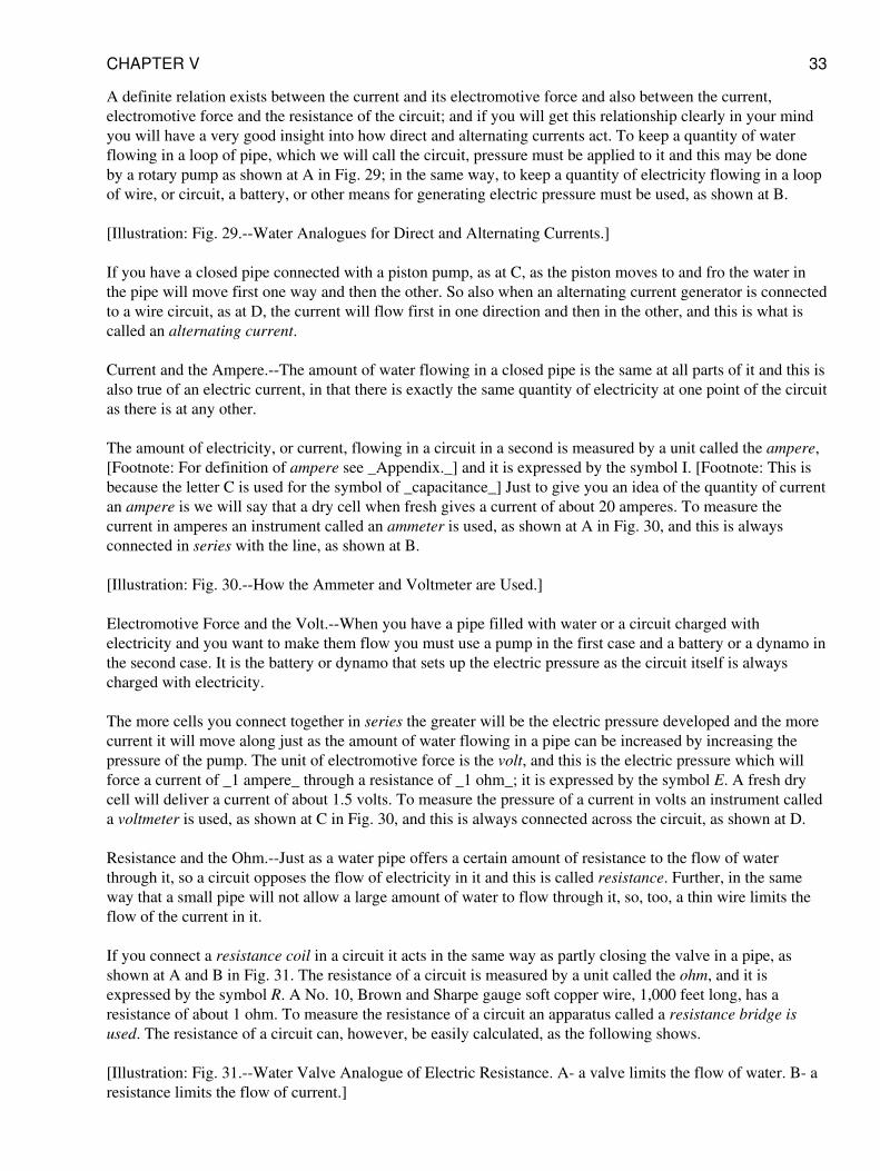
A definite relation exists between the current and its electromotive force and also between the current,electromotive force and the resistance of the circuit; and if you will get this relationship clearly in your mindyou will have a very good insight into how direct and alternating currents act. To keep a quantity of waterflowing in a loop of pipe, which we will call the circuit, pressure must be applied to it and this may be doneby a rotary pump as shown at A in Fig. 29; in the same way, to keep a quantity of electricity flowing in a loopof wire, or circuit, a battery, or other means for generating electric pressure must be used, as shown at B.
[Illustration: Fig. 29.--Water Analogues for Direct and Alternating Currents.]
If you have a closed pipe connected with a piston pump, as at C, as the piston moves to and fro the water inthe pipe will move first one way and then the other. So also when an alternating current generator is connectedto a wire circuit, as at D, the current will flow first in one direction and then in the other, and this is what iscalled an alternating current.
Current and the Ampere.--The amount of water flowing in a closed pipe is the same at all parts of it and this isalso true of an electric current, in that there is exactly the same quantity of electricity at one point of the circuitas there is at any other.
The amount of electricity, or current, flowing in a circuit in a second is measured by a unit called the ampere,[Footnote: For definition of ampere see _Appendix._] and it is expressed by the symbol I. [Footnote: This isbecause the letter C is used for the symbol of _capacitance_] Just to give you an idea of the quantity of currentan ampere is we will say that a dry cell when fresh gives a current of about 20 amperes. To measure thecurrent in amperes an instrument called an ammeter is used, as shown at A in Fig. 30, and this is alwaysconnected in series with the line, as shown at B.
[Illustration: Fig. 30.--How the Ammeter and Voltmeter are Used.]
Electromotive Force and the Volt.--When you have a pipe filled with water or a circuit charged withelectricity and you want to make them flow you must use a pump in the first case and a battery or a dynamo inthe second case. It is the battery or dynamo that sets up the electric pressure as the circuit itself is alwayscharged with electricity.
The more cells you connect together in series the greater will be the electric pressure developed and the morecurrent it will move along just as the amount of water flowing in a pipe can be increased by increasing thepressure of the pump. The unit of electromotive force is the volt, and this is the electric pressure which willforce a current of _1 ampere_ through a resistance of _1 ohm_; it is expressed by the symbol E. A fresh drycell will deliver a current of about 1.5 volts. To measure the pressure of a current in volts an instrument calleda voltmeter is used, as shown at C in Fig. 30, and this is always connected across the circuit, as shown at D.
Resistance and the Ohm.--Just as a water pipe offers a certain amount of resistance to the flow of waterthrough it, so a circuit opposes the flow of electricity in it and this is called resistance. Further, in the sameway that a small pipe will not allow a large amount of water to flow through it, so, too, a thin wire limits theflow of the current in it.
If you connect a resistance coil in a circuit it acts in the same way as partly closing the valve in a pipe, asshown at A and B in Fig. 31. The resistance of a circuit is measured by a unit called the ohm, and it isexpressed by the symbol R. A No. 10, Brown and Sharpe gauge soft copper wire, 1,000 feet long, has aresistance of about 1 ohm. To measure the resistance of a circuit an apparatus called a resistance bridge isused. The resistance of a circuit can, however, be easily calculated, as the following shows.
[Illustration: Fig. 31.--Water Valve Analogue of Electric Resistance. A- a valve limits the flow of water. B- aresistance limits the flow of current.]
CHAPTER V 33
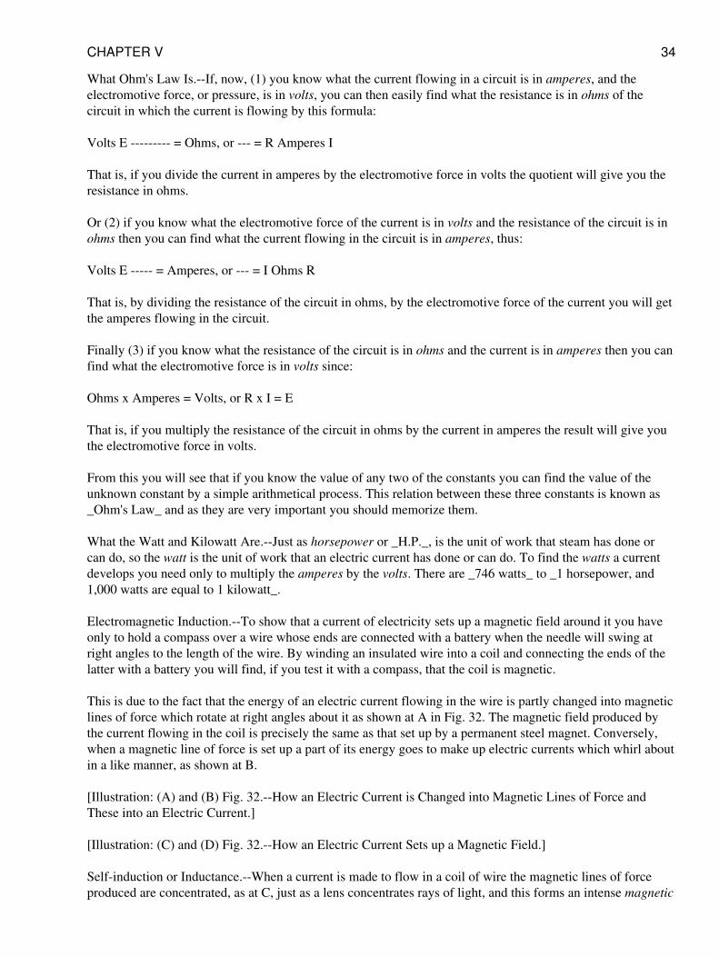
What Ohm's Law Is.--If, now, (1) you know what the current flowing in a circuit is in amperes, and theelectromotive force, or pressure, is in volts, you can then easily find what the resistance is in ohms of thecircuit in which the current is flowing by this formula:
Volts E --------- = Ohms, or --- = R Amperes I
That is, if you divide the current in amperes by the electromotive force in volts the quotient will give you theresistance in ohms.
Or (2) if you know what the electromotive force of the current is in volts and the resistance of the circuit is inohms then you can find what the current flowing in the circuit is in amperes, thus:
Volts E ----- = Amperes, or --- = I Ohms R
That is, by dividing the resistance of the circuit in ohms, by the electromotive force of the current you will getthe amperes flowing in the circuit.
Finally (3) if you know what the resistance of the circuit is in ohms and the current is in amperes then you canfind what the electromotive force is in volts since:
Ohms x Amperes = Volts, or R x I = E
That is, if you multiply the resistance of the circuit in ohms by the current in amperes the result will give youthe electromotive force in volts.
From this you will see that if you know the value of any two of the constants you can find the value of theunknown constant by a simple arithmetical process. This relation between these three constants is known as_Ohm's Law_ and as they are very important you should memorize them.
What the Watt and Kilowatt Are.--Just as horsepower or _H.P._, is the unit of work that steam has done orcan do, so the watt is the unit of work that an electric current has done or can do. To find the watts a currentdevelops you need only to multiply the amperes by the volts. There are _746 watts_ to _1 horsepower, and1,000 watts are equal to 1 kilowatt_.
Electromagnetic Induction.--To show that a current of electricity sets up a magnetic field around it you haveonly to hold a compass over a wire whose ends are connected with a battery when the needle will swing atright angles to the length of the wire. By winding an insulated wire into a coil and connecting the ends of thelatter with a battery you will find, if you test it with a compass, that the coil is magnetic.
This is due to the fact that the energy of an electric current flowing in the wire is partly changed into magneticlines of force which rotate at right angles about it as shown at A in Fig. 32. The magnetic field produced bythe current flowing in the coil is precisely the same as that set up by a permanent steel magnet. Conversely,when a magnetic line of force is set up a part of its energy goes to make up electric currents which whirl aboutin a like manner, as shown at B.
[Illustration: (A) and (B) Fig. 32.--How an Electric Current is Changed into Magnetic Lines of Force andThese into an Electric Current.]
[Illustration: (C) and (D) Fig. 32.--How an Electric Current Sets up a Magnetic Field.]
Self-induction or Inductance.--When a current is made to flow in a coil of wire the magnetic lines of forceproduced are concentrated, as at C, just as a lens concentrates rays of light, and this forms an intense magnetic
CHAPTER V 34
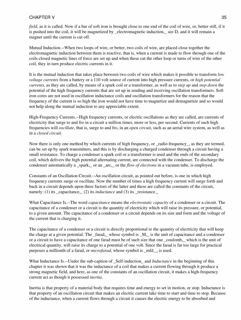
field, as it is called. Now if a bar of soft iron is brought close to one end of the coil of wire, or, better still, if itis pushed into the coil, it will be magnetized by _electromagnetic induction,_ see D, and it will remain amagnet until the current is cut off.
Mutual Induction.--When two loops of wire, or better, two coils of wire, are placed close together theelectromagnetic induction between them is reactive, that is, when a current is made to flow through one of thecoils closed magnetic lines of force are set up and when these cut the other loop or turns of wire of the othercoil, they in turn produce electric currents in it.
It is the mutual induction that takes place between two coils of wire which makes it possible to transform lowvoltage currents from a battery or a 110 volt source of current into high pressure currents, or high potentialcurrents, as they are called, by means of a spark coil or a transformer, as well as to step up and step down thepotential of the high frequency currents that are set up in sending and receiving oscillation transformers. Softiron cores are not used in oscillation inductance coils and oscillation transformers for the reason that thefrequency of the current is so high the iron would not have time to magnetize and demagnetize and so wouldnot help along the mutual induction to any appreciable extent.
High-Frequency Currents.--High frequency currents, or electric oscillations as they are called, are currents ofelectricity that surge to and fro in a circuit a million times, more or less, per second. Currents of such highfrequencies will oscillate, that is, surge to and fro, in an open circuit, such as an aerial wire system, as well asin a closed circuit.
Now there is only one method by which currents of high frequency, or _radio-frequency_, as they are termed,can be set up by spark transmitters, and this is by discharging a charged condenser through a circuit having asmall resistance. To charge a condenser a spark coil or a transformer is used and the ends of the secondarycoil, which delivers the high potential alternating current, are connected with the condenser. To discharge thecondenser automatically a _spark,_ or an _arc,_ or the flow of electrons in a vacuum tube, is employed.
Constants of an Oscillation Circuit.--An oscillation circuit, as pointed out before, is one in which highfrequency currents surge or oscillate. Now the number of times a high frequency current will surge forth andback in a circuit depends upon three factors of the latter and these are called the constants of the circuit,namely: (1) its _capacitance,_ (2) its inductance and (3) its _resistance._
What Capacitance Is.--The word capacitance means the electrostatic capacity of a condenser or a circuit. Thecapacitance of a condenser or a circuit is the quantity of electricity which will raise its pressure, or potential,to a given amount. The capacitance of a condenser or a circuit depends on its size and form and the voltage ofthe current that is charging it.
The capacitance of a condenser or a circuit is directly proportional to the quantity of electricity that will keepthe charge at a given potential. The _farad,_ whose symbol is _M,_ is the unit of capacitance and a condenseror a circuit to have a capacitance of one farad must be of such size that one _coulomb,_ which is the unit ofelectrical quantity, will raise its charge to a potential of one volt. Since the farad is far too large for practicalpurposes a millionth of a farad, or microfarad, whose symbol is _mfd._, is used.
What Inductance Is.--Under the sub-caption of _Self-induction_ and Inductance in the beginning of thischapter it was shown that it was the inductance of a coil that makes a current flowing through it produce astrong magnetic field, and here, as one of the constants of an oscillation circuit, it makes a high-frequencycurrent act as though it possessed inertia.
Inertia is that property of a material body that requires time and energy to set in motion, or stop. Inductance isthat property of an oscillation circuit that makes an electric current take time to start and time to stop. Becauseof the inductance, when a current flows through a circuit it causes the electric energy to be absorbed and
CHAPTER V 35
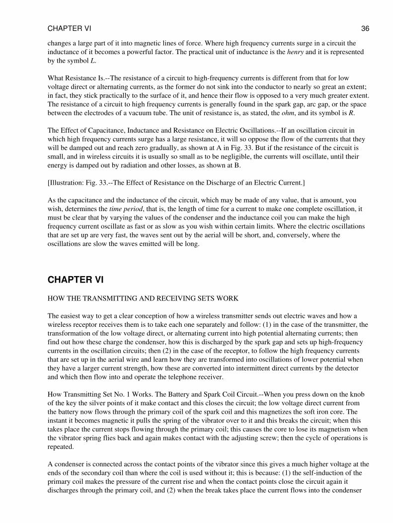
changes a large part of it into magnetic lines of force. Where high frequency currents surge in a circuit theinductance of it becomes a powerful factor. The practical unit of inductance is the henry and it is representedby the symbol L.
What Resistance Is.--The resistance of a circuit to high-frequency currents is different from that for lowvoltage direct or alternating currents, as the former do not sink into the conductor to nearly so great an extent;in fact, they stick practically to the surface of it, and hence their flow is opposed to a very much greater extent.The resistance of a circuit to high frequency currents is generally found in the spark gap, arc gap, or the spacebetween the electrodes of a vacuum tube. The unit of resistance is, as stated, the ohm, and its symbol is R.
The Effect of Capacitance, Inductance and Resistance on Electric Oscillations.--If an oscillation circuit inwhich high frequency currents surge has a large resistance, it will so oppose the flow of the currents that theywill be damped out and reach zero gradually, as shown at A in Fig. 33. But if the resistance of the circuit issmall, and in wireless circuits it is usually so small as to be negligible, the currents will oscillate, until theirenergy is damped out by radiation and other losses, as shown at B.
[Illustration: Fig. 33.--The Effect of Resistance on the Discharge of an Electric Current.]
As the capacitance and the inductance of the circuit, which may be made of any value, that is amount, youwish, determines the time period, that is, the length of time for a current to make one complete oscillation, itmust be clear that by varying the values of the condenser and the inductance coil you can make the highfrequency current oscillate as fast or as slow as you wish within certain limits. Where the electric oscillationsthat are set up are very fast, the waves sent out by the aerial will be short, and, conversely, where theoscillations are slow the waves emitted will be long.
CHAPTER VI
HOW THE TRANSMITTING AND RECEIVING SETS WORK
The easiest way to get a clear conception of how a wireless transmitter sends out electric waves and how awireless receptor receives them is to take each one separately and follow: (1) in the case of the transmitter, thetransformation of the low voltage direct, or alternating current into high potential alternating currents; thenfind out how these charge the condenser, how this is discharged by the spark gap and sets up high-frequencycurrents in the oscillation circuits; then (2) in the case of the receptor, to follow the high frequency currentsthat are set up in the aerial wire and learn how they are transformed into oscillations of lower potential whenthey have a larger current strength, how these are converted into intermittent direct currents by the detectorand which then flow into and operate the telephone receiver.
How Transmitting Set No. 1 Works. The Battery and Spark Coil Circuit.--When you press down on the knobof the key the silver points of it make contact and this closes the circuit; the low voltage direct current fromthe battery now flows through the primary coil of the spark coil and this magnetizes the soft iron core. Theinstant it becomes magnetic it pulls the spring of the vibrator over to it and this breaks the circuit; when thistakes place the current stops flowing through the primary coil; this causes the core to lose its magnetism whenthe vibrator spring flies back and again makes contact with the adjusting screw; then the cycle of operations isrepeated.
A condenser is connected across the contact points of the vibrator since this gives a much higher voltage at theends of the secondary coil than where the coil is used without it; this is because: (1) the self-induction of theprimary coil makes the pressure of the current rise and when the contact points close the circuit again itdischarges through the primary coil, and (2) when the break takes place the current flows into the condenser
CHAPTER VI 36
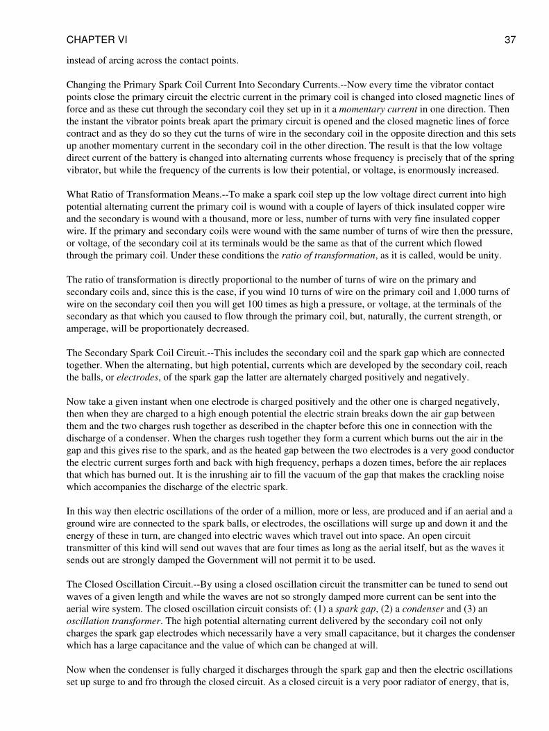
instead of arcing across the contact points.
Changing the Primary Spark Coil Current Into Secondary Currents.--Now every time the vibrator contactpoints close the primary circuit the electric current in the primary coil is changed into closed magnetic lines offorce and as these cut through the secondary coil they set up in it a momentary current in one direction. Thenthe instant the vibrator points break apart the primary circuit is opened and the closed magnetic lines of forcecontract and as they do so they cut the turns of wire in the secondary coil in the opposite direction and this setsup another momentary current in the secondary coil in the other direction. The result is that the low voltagedirect current of the battery is changed into alternating currents whose frequency is precisely that of the springvibrator, but while the frequency of the currents is low their potential, or voltage, is enormously increased.
What Ratio of Transformation Means.--To make a spark coil step up the low voltage direct current into highpotential alternating current the primary coil is wound with a couple of layers of thick insulated copper wireand the secondary is wound with a thousand, more or less, number of turns with very fine insulated copperwire. If the primary and secondary coils were wound with the same number of turns of wire then the pressure,or voltage, of the secondary coil at its terminals would be the same as that of the current which flowedthrough the primary coil. Under these conditions the ratio of transformation, as it is called, would be unity.
The ratio of transformation is directly proportional to the number of turns of wire on the primary andsecondary coils and, since this is the case, if you wind 10 turns of wire on the primary coil and 1,000 turns ofwire on the secondary coil then you will get 100 times as high a pressure, or voltage, at the terminals of thesecondary as that which you caused to flow through the primary coil, but, naturally, the current strength, oramperage, will be proportionately decreased.
The Secondary Spark Coil Circuit.--This includes the secondary coil and the spark gap which are connectedtogether. When the alternating, but high potential, currents which are developed by the secondary coil, reachthe balls, or electrodes, of the spark gap the latter are alternately charged positively and negatively.
Now take a given instant when one electrode is charged positively and the other one is charged negatively,then when they are charged to a high enough potential the electric strain breaks down the air gap betweenthem and the two charges rush together as described in the chapter before this one in connection with thedischarge of a condenser. When the charges rush together they form a current which burns out the air in thegap and this gives rise to the spark, and as the heated gap between the two electrodes is a very good conductorthe electric current surges forth and back with high frequency, perhaps a dozen times, before the air replacesthat which has burned out. It is the inrushing air to fill the vacuum of the gap that makes the crackling noisewhich accompanies the discharge of the electric spark.
In this way then electric oscillations of the order of a million, more or less, are produced and if an aerial and aground wire are connected to the spark balls, or electrodes, the oscillations will surge up and down it and theenergy of these in turn, are changed into electric waves which travel out into space. An open circuittransmitter of this kind will send out waves that are four times as long as the aerial itself, but as the waves itsends out are strongly damped the Government will not permit it to be used.
The Closed Oscillation Circuit.--By using a closed oscillation circuit the transmitter can be tuned to send outwaves of a given length and while the waves are not so strongly damped more current can be sent into theaerial wire system. The closed oscillation circuit consists of: (1) a spark gap, (2) a condenser and (3) anoscillation transformer. The high potential alternating current delivered by the secondary coil not onlycharges the spark gap electrodes which necessarily have a very small capacitance, but it charges the condenserwhich has a large capacitance and the value of which can be changed at will.
Now when the condenser is fully charged it discharges through the spark gap and then the electric oscillationsset up surge to and fro through the closed circuit. As a closed circuit is a very poor radiator of energy, that is,
CHAPTER VI 37
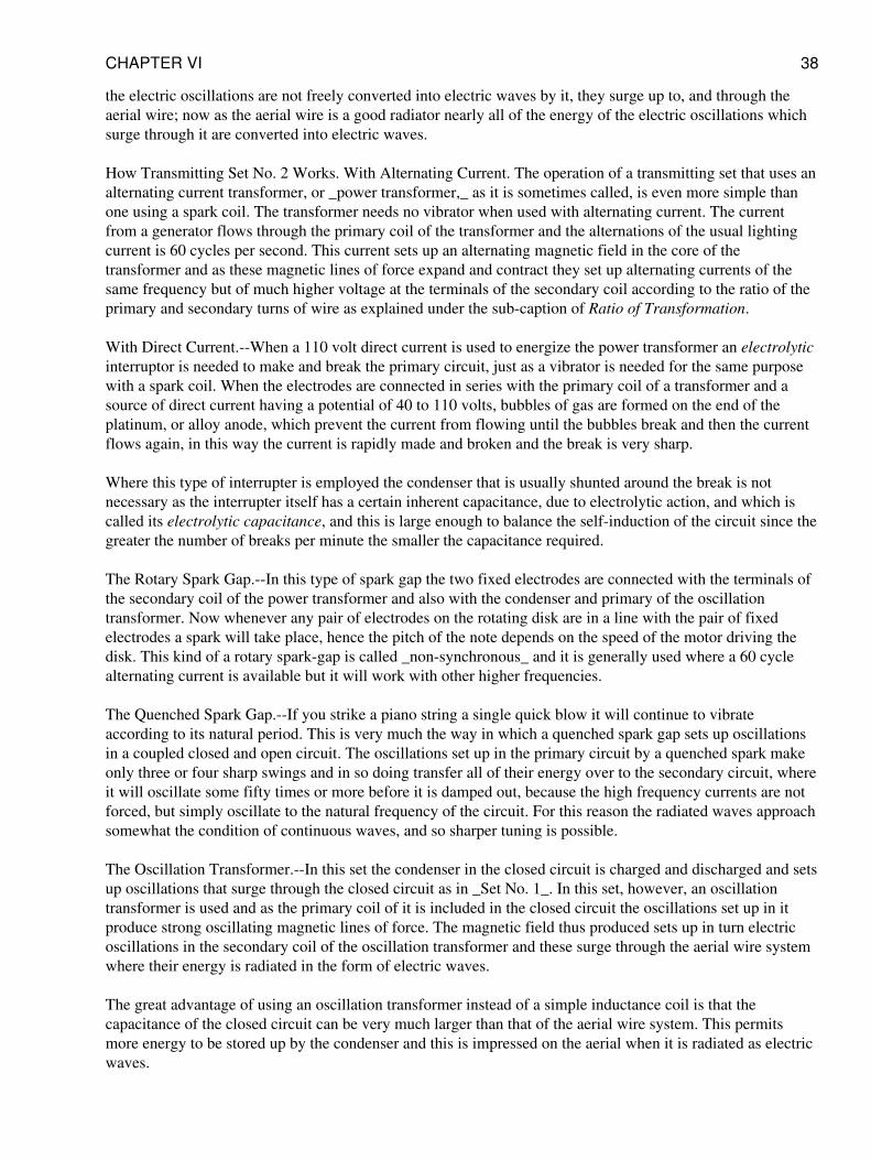
the electric oscillations are not freely converted into electric waves by it, they surge up to, and through theaerial wire; now as the aerial wire is a good radiator nearly all of the energy of the electric oscillations whichsurge through it are converted into electric waves.
How Transmitting Set No. 2 Works. With Alternating Current. The operation of a transmitting set that uses analternating current transformer, or _power transformer,_ as it is sometimes called, is even more simple thanone using a spark coil. The transformer needs no vibrator when used with alternating current. The currentfrom a generator flows through the primary coil of the transformer and the alternations of the usual lightingcurrent is 60 cycles per second. This current sets up an alternating magnetic field in the core of thetransformer and as these magnetic lines of force expand and contract they set up alternating currents of thesame frequency but of much higher voltage at the terminals of the secondary coil according to the ratio of theprimary and secondary turns of wire as explained under the sub-caption of Ratio of Transformation.
With Direct Current.--When a 110 volt direct current is used to energize the power transformer an electrolyticinterruptor is needed to make and break the primary circuit, just as a vibrator is needed for the same purposewith a spark coil. When the electrodes are connected in series with the primary coil of a transformer and asource of direct current having a potential of 40 to 110 volts, bubbles of gas are formed on the end of theplatinum, or alloy anode, which prevent the current from flowing until the bubbles break and then the currentflows again, in this way the current is rapidly made and broken and the break is very sharp.
Where this type of interrupter is employed the condenser that is usually shunted around the break is notnecessary as the interrupter itself has a certain inherent capacitance, due to electrolytic action, and which iscalled its electrolytic capacitance, and this is large enough to balance the self-induction of the circuit since thegreater the number of breaks per minute the smaller the capacitance required.
The Rotary Spark Gap.--In this type of spark gap the two fixed electrodes are connected with the terminals ofthe secondary coil of the power transformer and also with the condenser and primary of the oscillationtransformer. Now whenever any pair of electrodes on the rotating disk are in a line with the pair of fixedelectrodes a spark will take place, hence the pitch of the note depends on the speed of the motor driving thedisk. This kind of a rotary spark-gap is called _non-synchronous_ and it is generally used where a 60 cyclealternating current is available but it will work with other higher frequencies.
The Quenched Spark Gap.--If you strike a piano string a single quick blow it will continue to vibrateaccording to its natural period. This is very much the way in which a quenched spark gap sets up oscillationsin a coupled closed and open circuit. The oscillations set up in the primary circuit by a quenched spark makeonly three or four sharp swings and in so doing transfer all of their energy over to the secondary circuit, whereit will oscillate some fifty times or more before it is damped out, because the high frequency currents are notforced, but simply oscillate to the natural frequency of the circuit. For this reason the radiated waves approachsomewhat the condition of continuous waves, and so sharper tuning is possible.
The Oscillation Transformer.--In this set the condenser in the closed circuit is charged and discharged and setsup oscillations that surge through the closed circuit as in _Set No. 1_. In this set, however, an oscillationtransformer is used and as the primary coil of it is included in the closed circuit the oscillations set up in itproduce strong oscillating magnetic lines of force. The magnetic field thus produced sets up in turn electricoscillations in the secondary coil of the oscillation transformer and these surge through the aerial wire systemwhere their energy is radiated in the form of electric waves.
The great advantage of using an oscillation transformer instead of a simple inductance coil is that thecapacitance of the closed circuit can be very much larger than that of the aerial wire system. This permitsmore energy to be stored up by the condenser and this is impressed on the aerial when it is radiated as electricwaves.
CHAPTER VI 38
How Receiving Set No. I Works.--When the electric waves from a distant sending station impinge on the wireof a receiving aerial their energy is changed into electric oscillations that are of exactly the same frequency(assuming the receptor is tuned to the transmitter) but whose current strength (amperage) and potential(voltage) are very small. These electric waves surge through the closed circuit but when they reach the crystaldetector the contact of the metal point on the crystal permits more current to flow through it in one directionthan it will allow to pass in the other direction. For this reason a crystal detector is sometimes called arectifier, which it really is.
Thus the high frequency currents which the steel magnet cores of the telephone receiver would choke off arechanged by the detector into intermittent direct currents which can flow through the magnet coils of thetelephone receiver. Since the telephone receiver chokes off the oscillations, a small condenser can be shuntedaround it so that a complete closed oscillation circuit is formed and this gives better results.
When the intermittent rectified current flows through the coils of the telephone receiver it energizes themagnet as long as it lasts, when it is de-energized; this causes the soft iron disk, or diaphragm as it is called,which sets close to the ends of the poles of the magnet, to vibrate; and this in turn gives forth sounds such asdots and dashes, speech or music, according to the nature of the electric waves that sent them out at the distantstation.
How Receiving Set No. 2 Works.--When the electric oscillations that are set up by the incoming electricwaves on the aerial wire surge through the primary coil of the oscillation transformer they produce a magneticfield and as the lines of force of the latter cut the secondary coil, oscillations of the same frequency are set upin it. The potential (voltage) of these oscillations are, however, stepped down in the secondary coil and, hence,their current strength (amperes) is increased.
The oscillations then flow through the closed circuit where they are rectified by the crystal detector andtransformed into sound waves by the telephone receiver as described in connection with _Set No. 1_. Thevariable condenser shunted across the closed circuit permits finer secondary tuning to be done than is possiblewithout it. Where you are receiving continuous waves from a wireless telephone transmitter (speech or music)you have to tune sharper than is possible with the tuning coil alone and to do this a variable condenserconnected in parallel with the secondary coil is necessary.
CHAPTER VII
MECHANICAL AND ELECTRICAL TUNING
There is a strikingly close resemblance between sound waves and the way they are set up in the air by amechanically vibrating body, such as a steel spring or a tuning fork, and electric waves and the way they areset up in the ether by a current oscillating in a circuit. As it is easy to grasp the way that sound waves areproduced and behave something will be told about them in this chapter and also an explanation of how electricwaves are produced and behave and thus you will be able to get a clear understanding of them and of tuning ingeneral.
Damped and Sustained Mechanical Vibrations.--If you will place one end of a flat steel spring in a vice andscrew it up tight as shown at A in Fig. 34, and then pull the free end over and let it go it will vibrate to and frowith decreasing amplitude until it comes to rest as shown at B. When you pull the spring over you store upenergy in it and when you let it go the stored up energy is changed into energy of motion and the springmoves forth and back, or vibrates as we call it, until all of its stored up energy is spent.
[Illustration: Fig. 34.--Damped and Sustained Mechanical Vibrations.]
CHAPTER VII 39
If it were not for the air surrounding it and other frictional losses, the spring would vibrate for a very long timeas the stored up energy and the energy of motion would practically offset each other and so the energy wouldnot be used up. But as the spring beats the air the latter is sent out in impulses and the conversion of thevibrations of the spring into waves in the air soon uses up the energy you have imparted to it and it comes torest.
In order to send out continuous waves in the air instead of damped waves as with a flat steel spring you canuse an electric driven tuning fork, see C, in which an electromagnet is fixed on the inside of the prongs andwhen this is energized by a battery current the vibrations of the prongs of the fork are kept going, or aresustained, as shown in the diagram at D.
Damped and Sustained Electric Oscillations.--The vibrating steel spring described above is a very goodanalogue of the way that damped electric oscillations which surge in a circuit set up and send out periodicelectric waves in the ether while the electric driven tuning fork just described is likewise a good analogue ofhow sustained oscillations surge in a circuit and set up and send out continuous electric waves in the ether asthe following shows.
Now the inductance and resistance of a circuit such as is shown at A in Fig. 35, slows down, and finallydamps out entirely, the electric oscillations of the high frequency currents, see B, where these are set up by theperiodic discharge of a condenser, precisely as the vibrations of the spring are damped out by the friction ofthe air and other resistances that act upon it. As the electric oscillations surge to and fro in the circuit it isopposed by the action of the ether which surrounds it and electric waves are set up in and sent out through itand this transformation soon uses up the energy of the current that flows in the circuit.
[Illustration: Fig. 35.--Damped and Sustained Electric Oscillations.]
To send out continuous waves in the ether such as are needed for wireless telephony instead of damped waveswhich are, at the present writing, generally used for wireless telegraphy, an electric oscillation arc or avacuum tube oscillator must be used, see C, instead of a spark gap. Where a spark gap is used the condenserin the circuit is charged periodically and with considerable lapses of time between each of the chargingprocesses, when, of course, the condenser discharges periodically and with the same time element betweenthem. Where an oscillation arc or a vacuum tube is used the condenser is charged as rapidly as it is dischargedand the result is the oscillations are sustained as shown at D.
About Mechanical Tuning.--A tuning fork is better than a spring or a straight steel bar for setting upmechanical vibrations. As a matter of fact a tuning fork is simply a steel bar bent in the middle so that the twoends are parallel. A handle is attached to middle point of the fork so that it can be held easily and which alsoallows it to vibrate freely, when the ends of the prongs alternately approach and recede from one another.When the prongs vibrate the handle vibrates up and down in unison with it, and imparts its motion to thesounding box, or resonance case as it is sometimes called, where one is used.
If, now, you will mount the fork on a sounding box which is tuned so that it will be in resonance with thevibrations of the fork there will be a direct reinforcement of the vibrations when the note emitted by it will beaugmented in strength and quality. This is called simple resonance. Further, if you mount a pair of forks, eachon a separate sounding box, and have the forks of the same size, tone and pitch, and the boxes synchronized,that is, tuned to the same frequency of vibration, then set the two boxes a foot or so apart, as shown at A inFig. 36, when you strike one of the forks with a rubber hammer it will vibrate with a definite frequency and,hence, send out sound waves of a given length. When the latter strike the second fork the impact of themolecules of air of which the sound waves are formed will set its prongs to vibrating and it will, in turn, emitsound waves of the same length and this is called sympathetic resonance, or as we would say in wireless theforks are in tune.
CHAPTER VII 40
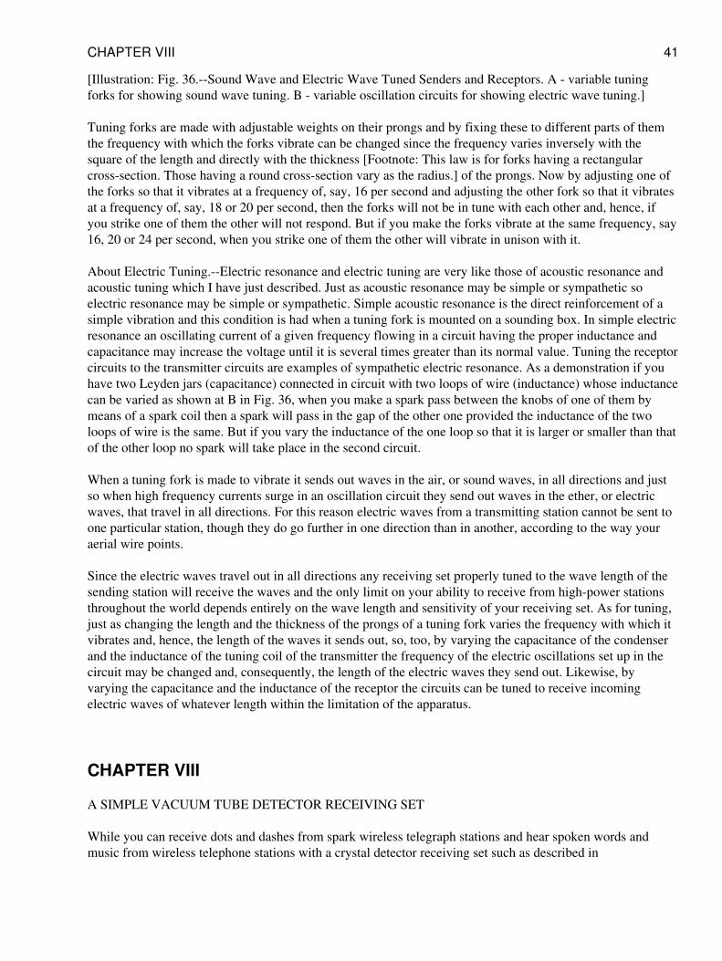
[Illustration: Fig. 36.--Sound Wave and Electric Wave Tuned Senders and Receptors. A - variable tuningforks for showing sound wave tuning. B - variable oscillation circuits for showing electric wave tuning.]
Tuning forks are made with adjustable weights on their prongs and by fixing these to different parts of themthe frequency with which the forks vibrate can be changed since the frequency varies inversely with thesquare of the length and directly with the thickness [Footnote: This law is for forks having a rectangularcross-section. Those having a round cross-section vary as the radius.] of the prongs. Now by adjusting one ofthe forks so that it vibrates at a frequency of, say, 16 per second and adjusting the other fork so that it vibratesat a frequency of, say, 18 or 20 per second, then the forks will not be in tune with each other and, hence, ifyou strike one of them the other will not respond. But if you make the forks vibrate at the same frequency, say16, 20 or 24 per second, when you strike one of them the other will vibrate in unison with it.
About Electric Tuning.--Electric resonance and electric tuning are very like those of acoustic resonance andacoustic tuning which I have just described. Just as acoustic resonance may be simple or sympathetic soelectric resonance may be simple or sympathetic. Simple acoustic resonance is the direct reinforcement of asimple vibration and this condition is had when a tuning fork is mounted on a sounding box. In simple electricresonance an oscillating current of a given frequency flowing in a circuit having the proper inductance andcapacitance may increase the voltage until it is several times greater than its normal value. Tuning the receptorcircuits to the transmitter circuits are examples of sympathetic electric resonance. As a demonstration if youhave two Leyden jars (capacitance) connected in circuit with two loops of wire (inductance) whose inductancecan be varied as shown at B in Fig. 36, when you make a spark pass between the knobs of one of them bymeans of a spark coil then a spark will pass in the gap of the other one provided the inductance of the twoloops of wire is the same. But if you vary the inductance of the one loop so that it is larger or smaller than thatof the other loop no spark will take place in the second circuit.
When a tuning fork is made to vibrate it sends out waves in the air, or sound waves, in all directions and justso when high frequency currents surge in an oscillation circuit they send out waves in the ether, or electricwaves, that travel in all directions. For this reason electric waves from a transmitting station cannot be sent toone particular station, though they do go further in one direction than in another, according to the way youraerial wire points.
Since the electric waves travel out in all directions any receiving set properly tuned to the wave length of thesending station will receive the waves and the only limit on your ability to receive from high-power stationsthroughout the world depends entirely on the wave length and sensitivity of your receiving set. As for tuning,just as changing the length and the thickness of the prongs of a tuning fork varies the frequency with which itvibrates and, hence, the length of the waves it sends out, so, too, by varying the capacitance of the condenserand the inductance of the tuning coil of the transmitter the frequency of the electric oscillations set up in thecircuit may be changed and, consequently, the length of the electric waves they send out. Likewise, byvarying the capacitance and the inductance of the receptor the circuits can be tuned to receive incomingelectric waves of whatever length within the limitation of the apparatus.
CHAPTER VIII
A SIMPLE VACUUM TUBE DETECTOR RECEIVING SET
While you can receive dots and dashes from spark wireless telegraph stations and hear spoken words andmusic from wireless telephone stations with a crystal detector receiving set such as described in
CHAPTER VIII 41
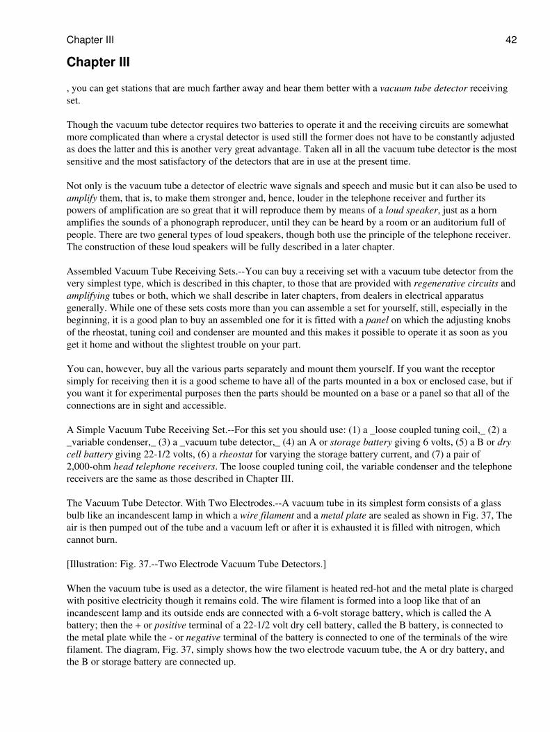
Chapter III
, you can get stations that are much farther away and hear them better with a vacuum tube detector receivingset.
Though the vacuum tube detector requires two batteries to operate it and the receiving circuits are somewhatmore complicated than where a crystal detector is used still the former does not have to be constantly adjustedas does the latter and this is another very great advantage. Taken all in all the vacuum tube detector is the mostsensitive and the most satisfactory of the detectors that are in use at the present time.
Not only is the vacuum tube a detector of electric wave signals and speech and music but it can also be used toamplify them, that is, to make them stronger and, hence, louder in the telephone receiver and further itspowers of amplification are so great that it will reproduce them by means of a loud speaker, just as a hornamplifies the sounds of a phonograph reproducer, until they can be heard by a room or an auditorium full ofpeople. There are two general types of loud speakers, though both use the principle of the telephone receiver.The construction of these loud speakers will be fully described in a later chapter.
Assembled Vacuum Tube Receiving Sets.--You can buy a receiving set with a vacuum tube detector from thevery simplest type, which is described in this chapter, to those that are provided with regenerative circuits andamplifying tubes or both, which we shall describe in later chapters, from dealers in electrical apparatusgenerally. While one of these sets costs more than you can assemble a set for yourself, still, especially in thebeginning, it is a good plan to buy an assembled one for it is fitted with a panel on which the adjusting knobsof the rheostat, tuning coil and condenser are mounted and this makes it possible to operate it as soon as youget it home and without the slightest trouble on your part.
You can, however, buy all the various parts separately and mount them yourself. If you want the receptorsimply for receiving then it is a good scheme to have all of the parts mounted in a box or enclosed case, but ifyou want it for experimental purposes then the parts should be mounted on a base or a panel so that all of theconnections are in sight and accessible.
A Simple Vacuum Tube Receiving Set.--For this set you should use: (1) a _loose coupled tuning coil,_ (2) a_variable condenser,_ (3) a _vacuum tube detector,_ (4) an A or storage battery giving 6 volts, (5) a B or drycell battery giving 22-1/2 volts, (6) a rheostat for varying the storage battery current, and (7) a pair of2,000-ohm head telephone receivers. The loose coupled tuning coil, the variable condenser and the telephonereceivers are the same as those described in Chapter III.
The Vacuum Tube Detector. With Two Electrodes.--A vacuum tube in its simplest form consists of a glassbulb like an incandescent lamp in which a wire filament and a metal plate are sealed as shown in Fig. 37, Theair is then pumped out of the tube and a vacuum left or after it is exhausted it is filled with nitrogen, whichcannot burn.
[Illustration: Fig. 37.--Two Electrode Vacuum Tube Detectors.]
When the vacuum tube is used as a detector, the wire filament is heated red-hot and the metal plate is chargedwith positive electricity though it remains cold. The wire filament is formed into a loop like that of anincandescent lamp and its outside ends are connected with a 6-volt storage battery, which is called the Abattery; then the + or positive terminal of a 22-1/2 volt dry cell battery, called the B battery, is connected tothe metal plate while the - or negative terminal of the battery is connected to one of the terminals of the wirefilament. The diagram, Fig. 37, simply shows how the two electrode vacuum tube, the A or dry battery, andthe B or storage battery are connected up.
Chapter III 42
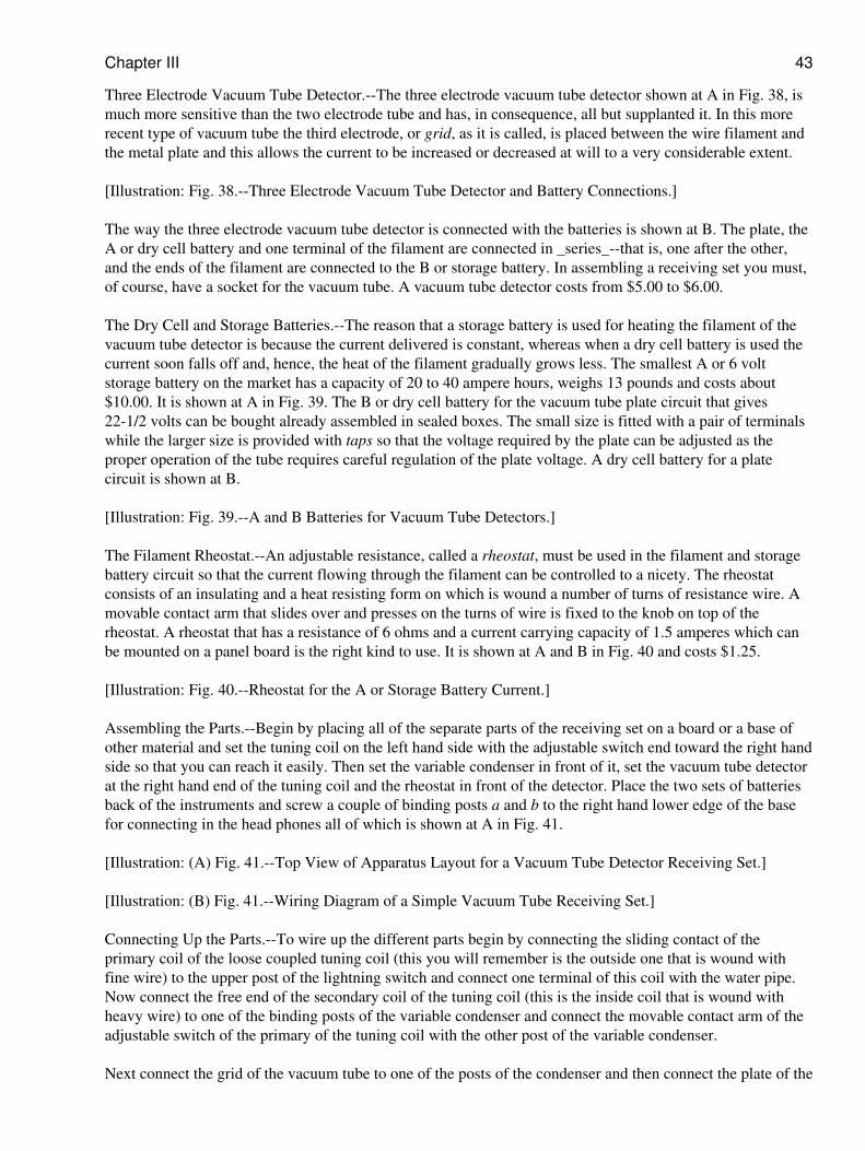
Three Electrode Vacuum Tube Detector.--The three electrode vacuum tube detector shown at A in Fig. 38, ismuch more sensitive than the two electrode tube and has, in consequence, all but supplanted it. In this morerecent type of vacuum tube the third electrode, or grid, as it is called, is placed between the wire filament andthe metal plate and this allows the current to be increased or decreased at will to a very considerable extent.
[Illustration: Fig. 38.--Three Electrode Vacuum Tube Detector and Battery Connections.]
The way the three electrode vacuum tube detector is connected with the batteries is shown at B. The plate, theA or dry cell battery and one terminal of the filament are connected in _series_--that is, one after the other,and the ends of the filament are connected to the B or storage battery. In assembling a receiving set you must,of course, have a socket for the vacuum tube. A vacuum tube detector costs from $5.00 to $6.00.
The Dry Cell and Storage Batteries.--The reason that a storage battery is used for heating the filament of thevacuum tube detector is because the current delivered is constant, whereas when a dry cell battery is used thecurrent soon falls off and, hence, the heat of the filament gradually grows less. The smallest A or 6 voltstorage battery on the market has a capacity of 20 to 40 ampere hours, weighs 13 pounds and costs about$10.00. It is shown at A in Fig. 39. The B or dry cell battery for the vacuum tube plate circuit that gives22-1/2 volts can be bought already assembled in sealed boxes. The small size is fitted with a pair of terminalswhile the larger size is provided with taps so that the voltage required by the plate can be adjusted as theproper operation of the tube requires careful regulation of the plate voltage. A dry cell battery for a platecircuit is shown at B.
[Illustration: Fig. 39.--A and B Batteries for Vacuum Tube Detectors.]
The Filament Rheostat.--An adjustable resistance, called a rheostat, must be used in the filament and storagebattery circuit so that the current flowing through the filament can be controlled to a nicety. The rheostatconsists of an insulating and a heat resisting form on which is wound a number of turns of resistance wire. Amovable contact arm that slides over and presses on the turns of wire is fixed to the knob on top of therheostat. A rheostat that has a resistance of 6 ohms and a current carrying capacity of 1.5 amperes which canbe mounted on a panel board is the right kind to use. It is shown at A and B in Fig. 40 and costs $1.25.
[Illustration: Fig. 40.--Rheostat for the A or Storage Battery Current.]
Assembling the Parts.--Begin by placing all of the separate parts of the receiving set on a board or a base ofother material and set the tuning coil on the left hand side with the adjustable switch end toward the right handside so that you can reach it easily. Then set the variable condenser in front of it, set the vacuum tube detectorat the right hand end of the tuning coil and the rheostat in front of the detector. Place the two sets of batteriesback of the instruments and screw a couple of binding posts a and b to the right hand lower edge of the basefor connecting in the head phones all of which is shown at A in Fig. 41.
[Illustration: (A) Fig. 41.--Top View of Apparatus Layout for a Vacuum Tube Detector Receiving Set.]
[Illustration: (B) Fig. 41.--Wiring Diagram of a Simple Vacuum Tube Receiving Set.]
Connecting Up the Parts.--To wire up the different parts begin by connecting the sliding contact of theprimary coil of the loose coupled tuning coil (this you will remember is the outside one that is wound withfine wire) to the upper post of the lightning switch and connect one terminal of this coil with the water pipe.Now connect the free end of the secondary coil of the tuning coil (this is the inside coil that is wound withheavy wire) to one of the binding posts of the variable condenser and connect the movable contact arm of theadjustable switch of the primary of the tuning coil with the other post of the variable condenser.
Next connect the grid of the vacuum tube to one of the posts of the condenser and then connect the plate of the
Chapter III 43
tube to the carbon terminal of the B or dry cell battery which is the + or positive pole and connect the zincterminal of the - or negative pole to the binding post a, connect the post b to the other side of the variablecondenser and then connect the terminals of the head phones to the binding posts a and b. Whatever you do becareful not to get the plate connections of the battery reversed.
Now connect one of the posts of the rheostat to one terminal of the filament and the other terminal of thefilament to the - or negative terminal of the A or storage battery and the + or positive terminal of the A orstorage battery to the other post of the rheostat. Finally connect the + or positive terminal of the A or storagebattery with the wire that runs from the head phones to the variable condenser, all of which is shown in thewiring diagram at B in Fig. 41.
Adjusting the Vacuum Tube Detector Receiving Set.--A vacuum tube detector is tuned exactly in the sameway as the _Crystal Detector Set No. 2_ described in Chapter III, in-so-far as the tuning coil and variablecondenser are concerned. The sensitivity of the vacuum tube detector receiving set and, hence, the distanceover which signals and other sounds can be heard depends very largely on the sensitivity of the vacuum tubeitself and this in turn depends on: (1) the right amount of heat developed by the filament, or filamentbrilliancy as it is called, (2) the right amount of voltage applied to the plate, and (3) the extent to which thetube is exhausted where this kind of a tube is used.
To vary the current flowing from the A or storage battery through the filament so that it will be heated to theright degree you adjust the rheostat while you are listening in to the signals or other sounds. By carefullyadjusting the rheostat you can easily find the point at which it makes the tube the most sensitive. A rheostat isalso useful in that it keeps the filament from burning out when the current from the battery first flows throughit. You can very often increase the sensitiveness of a vacuum tube after you have used it for a while byrecharging the A or storage battery.
The degree to which a vacuum tube has been exhausted has a very pronounced effect on its sensitivity. Thelonger the tube is used the lower its vacuum gets and generally the less sensitive it becomes. When this takesplace (and you can only guess at it) you can very often make it more sensitive by warming it over the flame ofa candle. Vacuum tubes having a gas content (in which case they are, of course, no longer vacuum tubes in thestrict sense) make better detectors than tubes from which the air has been exhausted and which are sealed offin this evacuated condition because their sensitiveness is not dependent on the degree of vacuum as in thelatter tubes. Moreover, a tube that is completely exhausted costs more than one that is filled with gas.
CHAPTER IX
VACUUM TUBE AMPLIFIER RECEIVING SETS
The reason a vacuum tube detector is more sensitive than a crystal detector is because while the latter merelyrectifies the oscillating current that surges in the receiving circuits, the former acts as an amplifier at the sametime. The vacuum tube can be used as a separate amplifier in connection with either: (1) a crystal detector or(2) a vacuum tube detector, and (_a_) it will amplify either the radio frequency currents, that is the highfrequency oscillating currents which are set up in the oscillation circuits or (_b_) it will amplify the audiofrequency currents, that is, the low frequency alternating currents that flow through the head phone circuit.
To use the amplified radio frequency oscillating currents or amplified audio frequency alternating currentsthat are set up by an amplifier tube either a high resistance, called a grid leak, or an amplifying transformer,with or without an iron core, must be connected with the plate circuit of the first amplifier tube and the gridcircuit of the next amplifier tube or detector tube, or with the wire point of a crystal detector. Where two ormore amplifier tubes are coupled together in this way the scheme is known as _cascade amplification._
CHAPTER IX 44
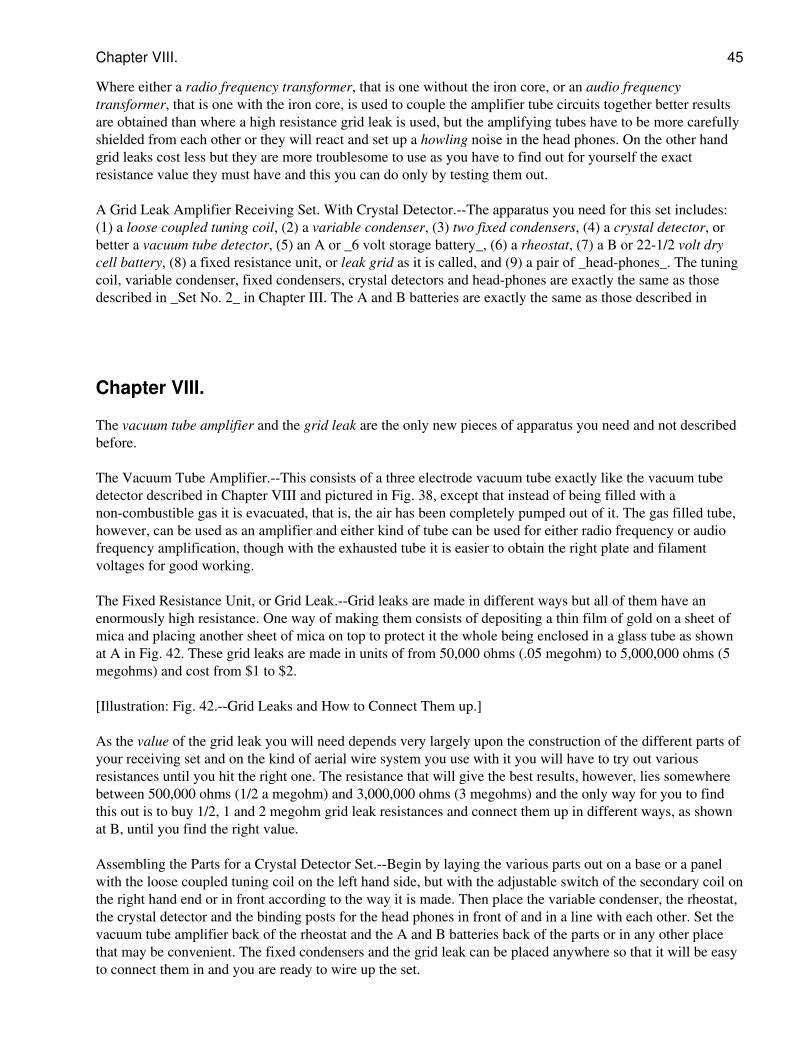
Where either a radio frequency transformer, that is one without the iron core, or an audio frequencytransformer, that is one with the iron core, is used to couple the amplifier tube circuits together better resultsare obtained than where a high resistance grid leak is used, but the amplifying tubes have to be more carefullyshielded from each other or they will react and set up a howling noise in the head phones. On the other handgrid leaks cost less but they are more troublesome to use as you have to find out for yourself the exactresistance value they must have and this you can do only by testing them out.
A Grid Leak Amplifier Receiving Set. With Crystal Detector.--The apparatus you need for this set includes:(1) a loose coupled tuning coil, (2) a variable condenser, (3) two fixed condensers, (4) a crystal detector, orbetter a vacuum tube detector, (5) an A or _6 volt storage battery_, (6) a rheostat, (7) a B or 22-1/2 volt drycell battery, (8) a fixed resistance unit, or leak grid as it is called, and (9) a pair of _head-phones_. The tuningcoil, variable condenser, fixed condensers, crystal detectors and head-phones are exactly the same as thosedescribed in _Set No. 2_ in Chapter III. The A and B batteries are exactly the same as those described in
Chapter VIII.
The vacuum tube amplifier and the grid leak are the only new pieces of apparatus you need and not describedbefore.
The Vacuum Tube Amplifier.--This consists of a three electrode vacuum tube exactly like the vacuum tubedetector described in Chapter VIII and pictured in Fig. 38, except that instead of being filled with anon-combustible gas it is evacuated, that is, the air has been completely pumped out of it. The gas filled tube,however, can be used as an amplifier and either kind of tube can be used for either radio frequency or audiofrequency amplification, though with the exhausted tube it is easier to obtain the right plate and filamentvoltages for good working.
The Fixed Resistance Unit, or Grid Leak.--Grid leaks are made in different ways but all of them have anenormously high resistance. One way of making them consists of depositing a thin film of gold on a sheet ofmica and placing another sheet of mica on top to protect it the whole being enclosed in a glass tube as shownat A in Fig. 42. These grid leaks are made in units of from 50,000 ohms (.05 megohm) to 5,000,000 ohms (5megohms) and cost from $1 to $2.
[Illustration: Fig. 42.--Grid Leaks and How to Connect Them up.]
As the value of the grid leak you will need depends very largely upon the construction of the different parts ofyour receiving set and on the kind of aerial wire system you use with it you will have to try out variousresistances until you hit the right one. The resistance that will give the best results, however, lies somewherebetween 500,000 ohms (1/2 a megohm) and 3,000,000 ohms (3 megohms) and the only way for you to findthis out is to buy 1/2, 1 and 2 megohm grid leak resistances and connect them up in different ways, as shownat B, until you find the right value.
Assembling the Parts for a Crystal Detector Set.--Begin by laying the various parts out on a base or a panelwith the loose coupled tuning coil on the left hand side, but with the adjustable switch of the secondary coil onthe right hand end or in front according to the way it is made. Then place the variable condenser, the rheostat,the crystal detector and the binding posts for the head phones in front of and in a line with each other. Set thevacuum tube amplifier back of the rheostat and the A and B batteries back of the parts or in any other placethat may be convenient. The fixed condensers and the grid leak can be placed anywhere so that it will be easyto connect them in and you are ready to wire up the set.
Chapter VIII. 45
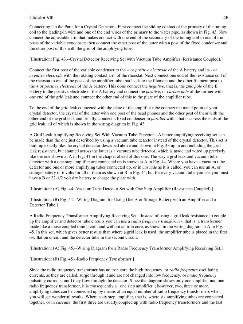
Connecting Up the Parts for a Crystal Detector.--First connect the sliding contact of the primary of the tuningcoil to the leading-in wire and one of the end wires of the primary to the water pipe, as shown in Fig. 43. Nowconnect the adjustable arm that makes contact with one end of the secondary of the tuning coil to one of theposts of the variable condenser; then connect the other post of the latter with a post of the fixed condenser andthe other post of this with the grid of the amplifying tube.
[Illustration: Fig. 43.--Crystal Detector Receiving Set with Vacuum Tube Amplifier (Resistance Coupled).]
Connect the first post of the variable condenser to the + or positive electrode of the A battery and its - ornegative electrode with the rotating contact arm of the rheostat. Next connect one end of the resistance coil ofthe rheostat to one of the posts of the amplifier tube that leads to the filament and the other filament post tothe + or positive electrode of the A battery. This done connect the negative, that is, the zinc pole of the Bbattery to the positive electrode of the A battery and connect the positive, or carbon pole of the former withone end of the grid leak and connect the other end of this to the plate of the amplifier tube.
To the end of the grid leak connected with the plate of the amplifier tube connect the metal point of yourcrystal detector, the crystal of the latter with one post of the head phones and the other post of them with theother end of the grid leak and, finally, connect a fixed condenser in parallel with--that is across the ends of thegrid leak, all of which is shown in the wiring diagram in Fig. 43.
A Grid Leak Amplifying Receiving Set With Vacuum Tube Detector.--A better amplifying receiving set canbe made than the one just described by using a vacuum tube detector instead of the crystal detector. This set isbuilt up exactly like the crystal detector described above and shown in Fig. 43 up to and including the gridleak resistance, but shunted across the latter is a vacuum tube detector, which is made and wired up preciselylike the one shown at A in Fig. 41 in the chapter ahead of this one. The way a grid leak and vacuum tubedetector with a one-step amplifier are connected up is shown at A in Fig. 44. Where you have a vacuum tubedetector and one or more amplifying tubes connected up, or in cascade as it is called, you can use an A, orstorage battery of 6 volts for all of them as shown at B in Fig. 44, but for every vacuum tube you use you musthave a B or 22-1/2 volt dry battery to charge the plate with.
[Illustration: (A) Fig. 44--Vacuum Tube Detector Set with One Step Amplifier (Resistance Coupled).]
[Illustration: (B) Fig. 44.--Wiring Diagram for Using One A or Storage Battery with an Amplifier and aDetector Tube.]
A Radio Frequency Transformer Amplifying Receiving Set.--Instead of using a grid leak resistance to coupleup the amplifier and detector tube circuits you can use a radio frequency transformer, that is, a transformermade like a loose coupled tuning coil, and without an iron core, as shown in the wiring diagram at A in Fig.45. In this set, which gives better results than where a grid leak is used, the amplifier tube is placed in the firstoscillation circuit and the detector tube in the second circuit.
[Illustration: (A) Fig. 45.--Wiring Diagram for a Radio Frequency Transformer Amplifying Receiving Set.]
[Illustration: (B) Fig. 45.--Radio Frequency Transformer.]
Since the radio frequency transformer has no iron core the high frequency, or radio frequency oscillatingcurrents, as they are called, surge through it and are not changed into low frequency, or audio frequencypulsating currents, until they flow through the detector. Since the diagram shows only one amplifier and oneradio frequency transformer, it is consequently a _one step amplifier_; however, two, three or more,amplifying tubes can be connected up by means of an equal number of radio frequency transformers whenyou will get wonderful results. Where a six step amplifier, that is, where six amplifying tubes are connectedtogether, or in cascade, the first three are usually coupled up with radio frequency transformers and the last
Chapter VIII. 46
three with audio frequency transformers. A radio frequency transformer is shown at B and costs $6 to $7.
An Audio Frequency Transformer Amplifying Receiving Set.--Where audio frequency transformers are usedfor stepping up the voltage of the current of the detector and amplifier tubes, the radio frequency current doesnot get into the plate circuit of the detector at all for the reason that the iron core of the transformer chokesthem off, hence, the succeeding amplifiers operate at audio frequencies. An audio frequency transformer isshown at A in Fig. 46 and a wiring diagram showing how the tubes are connected in cascade with thetransformers is shown at B; it is therefore a two-step audio frequency receiving set.
[Illustration: (A) Fig. 46.--Audio Frequency Transformer.]
[Illustration: (B) Fig. 46--Wiring Diagram for an Audio Frequency Transformer Amplifying Receiving Set.(With Vacuum Tube Detector and Two Step Amplifier Tubes.)]
A Six Step Amplifier Receiving Set With a Loop Aerial.--By using a receiving set having a three step radiofrequency and a three step audio frequency, that is, a set in which there are coupled three amplifying tubeswith radio frequency transformers and three amplifying tubes with audio frequency transformers as describedunder the caption A Radio Frequency Transformer Receiving Set, you can use a loop aerial in your room thusgetting around the difficulties--if such there be--in erecting an out-door aerial. You can easily make a loopaerial by winding 10 turns of _No. 14_ or _16_ copper wire about 1/16 inch apart on a wooden frame two feeton the side as shown in Fig. 47. With this six step amplifier set and loop aerial you can receive wave lengthsof 150 to 600 meters from various high power stations which are at considerable distances away.
[Illustration: (A) Fig. 47.--Six Step Amplifier with Loop Aerial.]
[Illustration: (B) Fig. 47.--Efficient Regenerative Receiving Set. (With Three Coil Loose Coupler Tuner.)]
How to Prevent Howling.--Where radio frequency or audio frequency amplifiers are used to couple youramplifier tubes in cascade you must take particular pains to shield them from one another in order to preventthe feed back of the currents through them, which makes the head phones or loud speaker howl. To shieldthem from each other the tubes should be enclosed in metal boxes and placed at least 6 inches apart while thetransformers should be set so that their cores are at right angles to each other and these also should be not lessthan six inches apart.
CHAPTER X
REGENERATIVE AMPLIFICATION RECEIVING SETS
While a vacuum tube detector has an amplifying action of its own, and this accounts for its greatsensitiveness, its amplifying action can be further increased to an enormous extent by making the radiofrequency currents that are set up in the oscillation circuits react on the detector.
Such currents are called _feed-back_ or regenerative currents and when circuits are so arranged as to causethe currents to flow back through the detector tube the amplification keeps on increasing until the capacity ofthe tube itself is reached. It is like using steam over and over again in a steam turbine until there is no moreenergy left in it. A system of circuits which will cause this regenerative action to take place is known as theArmstrong circuits and is so called after the young man who discovered it.
Since the regenerative action of the radio frequency currents is produced by the detector tube itself and whichsets up an amplifying effect without the addition of an amplifying tube, this type of receiving set has found
CHAPTER X 47
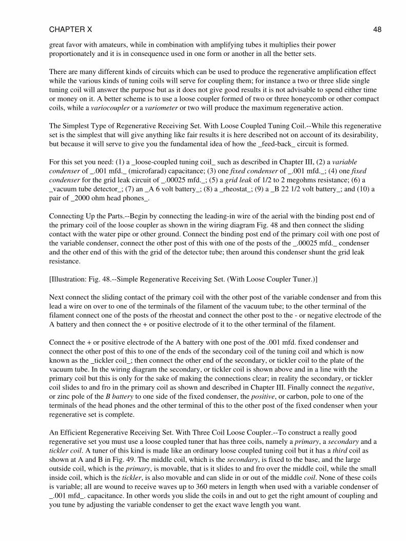
great favor with amateurs, while in combination with amplifying tubes it multiplies their powerproportionately and it is in consequence used in one form or another in all the better sets.
There are many different kinds of circuits which can be used to produce the regenerative amplification effectwhile the various kinds of tuning coils will serve for coupling them; for instance a two or three slide singletuning coil will answer the purpose but as it does not give good results it is not advisable to spend either timeor money on it. A better scheme is to use a loose coupler formed of two or three honeycomb or other compactcoils, while a variocoupler or a variometer or two will produce the maximum regenerative action.
The Simplest Type of Regenerative Receiving Set. With Loose Coupled Tuning Coil.--While this regenerativeset is the simplest that will give anything like fair results it is here described not on account of its desirability,but because it will serve to give you the fundamental idea of how the _feed-back_ circuit is formed.
For this set you need: (1) a _loose-coupled tuning coil_ such as described in Chapter III, (2) a variablecondenser of _.001 mfd._ (microfarad) capacitance; (3) one fixed condenser of _.001 mfd._; (4) one fixedcondenser for the grid leak circuit of _.00025 mfd._; (5) a grid leak of 1/2 to 2 megohms resistance; (6) a_vacuum tube detector_; (7) an _A 6 volt battery_; (8) a _rheostat_; (9) a _B 22 1/2 volt battery_; and (10) apair of _2000 ohm head phones_.
Connecting Up the Parts.--Begin by connecting the leading-in wire of the aerial with the binding post end ofthe primary coil of the loose coupler as shown in the wiring diagram Fig. 48 and then connect the slidingcontact with the water pipe or other ground. Connect the binding post end of the primary coil with one post ofthe variable condenser, connect the other post of this with one of the posts of the _.00025 mfd._ condenserand the other end of this with the grid of the detector tube; then around this condenser shunt the grid leakresistance.
[Illustration: Fig. 48.--Simple Regenerative Receiving Set. (With Loose Coupler Tuner.)]
Next connect the sliding contact of the primary coil with the other post of the variable condenser and from thislead a wire on over to one of the terminals of the filament of the vacuum tube; to the other terminal of thefilament connect one of the posts of the rheostat and connect the other post to the - or negative electrode of theA battery and then connect the + or positive electrode of it to the other terminal of the filament.
Connect the + or positive electrode of the A battery with one post of the .001 mfd. fixed condenser andconnect the other post of this to one of the ends of the secondary coil of the tuning coil and which is nowknown as the _tickler coil_; then connect the other end of the secondary, or tickler coil to the plate of thevacuum tube. In the wiring diagram the secondary, or tickler coil is shown above and in a line with theprimary coil but this is only for the sake of making the connections clear; in reality the secondary, or ticklercoil slides to and fro in the primary coil as shown and described in Chapter III. Finally connect the negative,or zinc pole of the B battery to one side of the fixed condenser, the positive, or carbon, pole to one of theterminals of the head phones and the other terminal of this to the other post of the fixed condenser when yourregenerative set is complete.
An Efficient Regenerative Receiving Set. With Three Coil Loose Coupler.--To construct a really goodregenerative set you must use a loose coupled tuner that has three coils, namely a primary, a secondary and atickler coil. A tuner of this kind is made like an ordinary loose coupled tuning coil but it has a third coil asshown at A and B in Fig. 49. The middle coil, which is the secondary, is fixed to the base, and the largeoutside coil, which is the primary, is movable, that is it slides to and fro over the middle coil, while the smallinside coil, which is the tickler, is also movable and can slide in or out of the middle coil. None of these coilsis variable; all are wound to receive waves up to 360 meters in length when used with a variable condenser of_.001 mfd_. capacitance. In other words you slide the coils in and out to get the right amount of coupling andyou tune by adjusting the variable condenser to get the exact wave length you want.
CHAPTER X 48
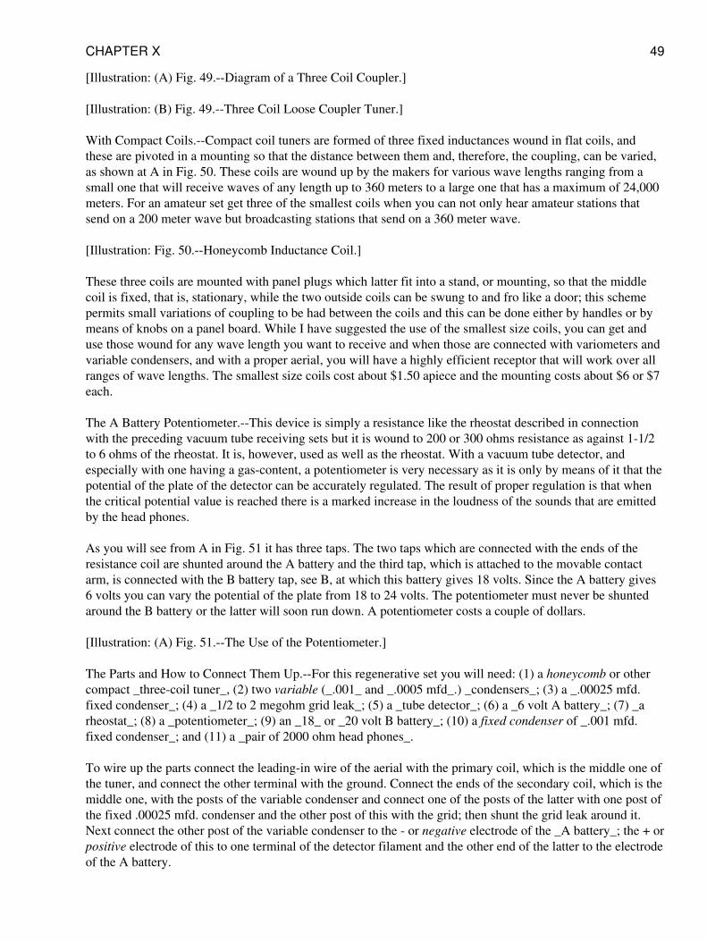
[Illustration: (A) Fig. 49.--Diagram of a Three Coil Coupler.]
[Illustration: (B) Fig. 49.--Three Coil Loose Coupler Tuner.]
With Compact Coils.--Compact coil tuners are formed of three fixed inductances wound in flat coils, andthese are pivoted in a mounting so that the distance between them and, therefore, the coupling, can be varied,as shown at A in Fig. 50. These coils are wound up by the makers for various wave lengths ranging from asmall one that will receive waves of any length up to 360 meters to a large one that has a maximum of 24,000meters. For an amateur set get three of the smallest coils when you can not only hear amateur stations thatsend on a 200 meter wave but broadcasting stations that send on a 360 meter wave.
[Illustration: Fig. 50.--Honeycomb Inductance Coil.]
These three coils are mounted with panel plugs which latter fit into a stand, or mounting, so that the middlecoil is fixed, that is, stationary, while the two outside coils can be swung to and fro like a door; this schemepermits small variations of coupling to be had between the coils and this can be done either by handles or bymeans of knobs on a panel board. While I have suggested the use of the smallest size coils, you can get anduse those wound for any wave length you want to receive and when those are connected with variometers andvariable condensers, and with a proper aerial, you will have a highly efficient receptor that will work over allranges of wave lengths. The smallest size coils cost about $1.50 apiece and the mounting costs about $6 or $7each.
The A Battery Potentiometer.--This device is simply a resistance like the rheostat described in connectionwith the preceding vacuum tube receiving sets but it is wound to 200 or 300 ohms resistance as against 1-1/2to 6 ohms of the rheostat. It is, however, used as well as the rheostat. With a vacuum tube detector, andespecially with one having a gas-content, a potentiometer is very necessary as it is only by means of it that thepotential of the plate of the detector can be accurately regulated. The result of proper regulation is that whenthe critical potential value is reached there is a marked increase in the loudness of the sounds that are emittedby the head phones.
As you will see from A in Fig. 51 it has three taps. The two taps which are connected with the ends of theresistance coil are shunted around the A battery and the third tap, which is attached to the movable contactarm, is connected with the B battery tap, see B, at which this battery gives 18 volts. Since the A battery gives6 volts you can vary the potential of the plate from 18 to 24 volts. The potentiometer must never be shuntedaround the B battery or the latter will soon run down. A potentiometer costs a couple of dollars.
[Illustration: (A) Fig. 51.--The Use of the Potentiometer.]
The Parts and How to Connect Them Up.--For this regenerative set you will need: (1) a honeycomb or othercompact _three-coil tuner_, (2) two variable (_.001_ and _.0005 mfd_.) _condensers_; (3) a _.00025 mfd.fixed condenser_; (4) a _1/2 to 2 megohm grid leak_; (5) a _tube detector_; (6) a _6 volt A battery_; (7) _arheostat_; (8) a _potentiometer_; (9) an _18_ or _20 volt B battery_; (10) a fixed condenser of _.001 mfd.fixed condenser_; and (11) a _pair of 2000 ohm head phones_.
To wire up the parts connect the leading-in wire of the aerial with the primary coil, which is the middle one ofthe tuner, and connect the other terminal with the ground. Connect the ends of the secondary coil, which is themiddle one, with the posts of the variable condenser and connect one of the posts of the latter with one post ofthe fixed .00025 mfd. condenser and the other post of this with the grid; then shunt the grid leak around it.Next connect the other post of the variable condenser to the - or negative electrode of the _A battery_; the + orpositive electrode of this to one terminal of the detector filament and the other end of the latter to the electrodeof the A battery.
CHAPTER X 49
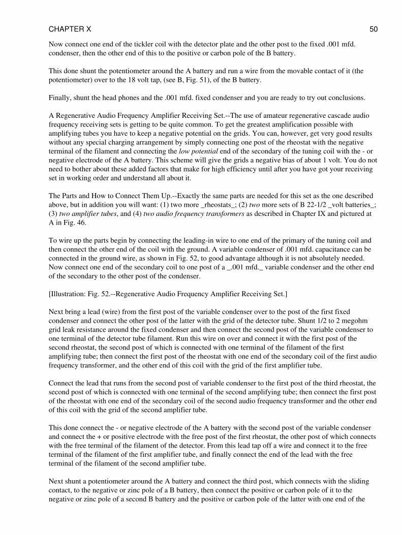
Now connect one end of the tickler coil with the detector plate and the other post to the fixed .001 mfd.condenser, then the other end of this to the positive or carbon pole of the B battery.
This done shunt the potentiometer around the A battery and run a wire from the movable contact of it (thepotentiometer) over to the 18 volt tap, (see B, Fig. 51), of the B battery.
Finally, shunt the head phones and the .001 mfd. fixed condenser and you are ready to try out conclusions.
A Regenerative Audio Frequency Amplifier Receiving Set.--The use of amateur regenerative cascade audiofrequency receiving sets is getting to be quite common. To get the greatest amplification possible withamplifying tubes you have to keep a negative potential on the grids. You can, however, get very good resultswithout any special charging arrangement by simply connecting one post of the rheostat with the negativeterminal of the filament and connecting the low potential end of the secondary of the tuning coil with the - ornegative electrode of the A battery. This scheme will give the grids a negative bias of about 1 volt. You do notneed to bother about these added factors that make for high efficiency until after you have got your receivingset in working order and understand all about it.
The Parts and How to Connect Them Up.--Exactly the same parts are needed for this set as the one describedabove, but in addition you will want: (1) two more _rheostats_; (2) two more sets of B 22-1/2 _volt batteries_;(3) two amplifier tubes, and (4) two audio frequency transformers as described in Chapter IX and pictured atA in Fig. 46.
To wire up the parts begin by connecting the leading-in wire to one end of the primary of the tuning coil andthen connect the other end of the coil with the ground. A variable condenser of .001 mfd. capacitance can beconnected in the ground wire, as shown in Fig. 52, to good advantage although it is not absolutely needed.Now connect one end of the secondary coil to one post of a _.001 mfd._ variable condenser and the other endof the secondary to the other post of the condenser.
[Illustration: Fig. 52.--Regenerative Audio Frequency Amplifier Receiving Set.]
Next bring a lead (wire) from the first post of the variable condenser over to the post of the first fixedcondenser and connect the other post of the latter with the grid of the detector tube. Shunt 1/2 to 2 megohmgrid leak resistance around the fixed condenser and then connect the second post of the variable condenser toone terminal of the detector tube filament. Run this wire on over and connect it with the first post of thesecond rheostat, the second post of which is connected with one terminal of the filament of the firstamplifying tube; then connect the first post of the rheostat with one end of the secondary coil of the first audiofrequency transformer, and the other end of this coil with the grid of the first amplifier tube.
Connect the lead that runs from the second post of variable condenser to the first post of the third rheostat, thesecond post of which is connected with one terminal of the second amplifying tube; then connect the first postof the rheostat with one end of the secondary coil of the second audio frequency transformer and the other endof this coil with the grid of the second amplifier tube.
This done connect the - or negative electrode of the A battery with the second post of the variable condenserand connect the + or positive electrode with the free post of the first rheostat, the other post of which connectswith the free terminal of the filament of the detector. From this lead tap off a wire and connect it to the freeterminal of the filament of the first amplifier tube, and finally connect the end of the lead with the freeterminal of the filament of the second amplifier tube.
Next shunt a potentiometer around the A battery and connect the third post, which connects with the slidingcontact, to the negative or zinc pole of a B battery, then connect the positive or carbon pole of it to thenegative or zinc pole of a second B battery and the positive or carbon pole of the latter with one end of the
CHAPTER X 50
primary coil of the second audio frequency transformer and the other end of it to the plate of the firstamplifying tube. Run the lead on over and connect it to one of the terminals of the second fixed condenser andthe other terminal of this with the plate of the second amplifying tube. Then shunt the headphones around thecondenser.
Finally connect one end of the tickler coil of the tuner with the plate of the detector tube and connect the otherend of the tickler to one end of the primary coil of the first audio frequency transformer and the other end of itto the wire that connects the two B batteries together.
CHAPTER XI
SHORT WAVE REGENERATIVE RECEIVING SETS
A short wave receiving set is one that will receive a range of wave lengths of from 150 to 600 meters whilethe distance over which the waves can be received as well as the intensity of the sounds reproduced by theheadphones depends on: (1) whether it is a regenerative set and (2) whether it is provided with amplifyingtubes.
High-grade regenerative sets designed especially for receiving amateur sending stations that must use a shortwave length are built on the regenerative principle just like those described in the last chapter and furtheramplification can be had by the use of amplifier tubes as explained in Chapter IX, but the new feature of thesesets is the use of the variocoupler and one or more variometers. These tuning devices can be connected up indifferent ways and are very popular with amateurs at the present time.
Differing from the ordinary loose coupler the variometer has no movable contacts while the variometer isprovided with taps so that you can connect it up for the wave length you want to receive. All you have to do isto tune the oscillation circuits to each other is to turn the rotor, which is the secondary coil, around in thestator, as the primary coil is called in order to get a very fine variation of the wave length. It is thisconstruction that makes sharp tuning with these sets possible, by which is meant that all wave lengths aretuned out except the one which the receiving set is tuned for.
A Short Wave Regenerative Receiver--With One Variometer and Three Variable Condensers.--This set alsoincludes a variocoupler and a grid coil. The way that the parts are connected together makes it a simple and atthe same time a very efficient regenerative receiver for short waves. While this set can be used withoutshielding the parts from each other the best results are had when shields are used.
The parts you need for this set include: (1) one _variocoupler_; (2) one _.001 microfarad variable condenser_;(3) one _.0005 microfarad variable condenser_; (4) one _.0007 microfarad variable condenser_; (5) _one 2megohm grid leak_; (6) one _vacuum tube detector_; (7) one _6 volt A battery_; (8) one _6 ohm_, 1-1/2_ampere rheostat_; (9) one _200 ohm potentiometer_; (10) one 22-1/2 _volt B battery_; (11) one _.001microfarad fixed condenser_, (12) one pair of _2,000 ohm headphones_, and (13) a variometer.
The Variocoupler.--A variocoupler consists of a primary coil wound on the outside of a tube of insulatingmaterial and to certain turns of this taps are connected so that you can fix the wave length which your aerialsystem is to receive from the shortest wave; i.e., 150 meters on up by steps to the longest wave, i.e., 600meters, which is the range of most amateur variocouplers that are sold in the open market. This is the part ofthe variocoupler that is called the stator.
The secondary coil is wound on the section of a ball mounted on a shaft and this is swung in bearings on thestator so that it can turn in it. This part of the variocoupler is called the rotor and is arranged so that it can be
CHAPTER XI 51
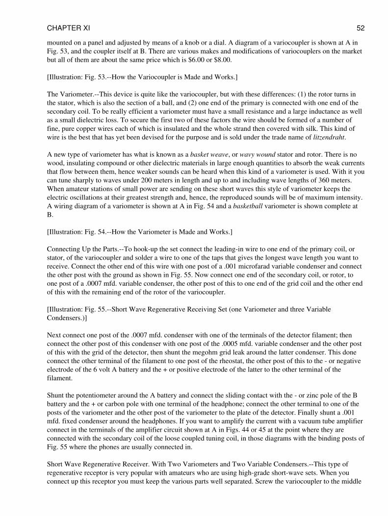
mounted on a panel and adjusted by means of a knob or a dial. A diagram of a variocoupler is shown at A inFig. 53, and the coupler itself at B. There are various makes and modifications of variocouplers on the marketbut all of them are about the same price which is $6.00 or $8.00.
[Illustration: Fig. 53.--How the Variocoupler is Made and Works.]
The Variometer.--This device is quite like the variocoupler, but with these differences: (1) the rotor turns inthe stator, which is also the section of a ball, and (2) one end of the primary is connected with one end of thesecondary coil. To be really efficient a variometer must have a small resistance and a large inductance as wellas a small dielectric loss. To secure the first two of these factors the wire should be formed of a number offine, pure copper wires each of which is insulated and the whole strand then covered with silk. This kind ofwire is the best that has yet been devised for the purpose and is sold under the trade name of litzendraht.
A new type of variometer has what is known as a basket weave, or wavy wound stator and rotor. There is nowood, insulating compound or other dielectric materials in large enough quantities to absorb the weak currentsthat flow between them, hence weaker sounds can be heard when this kind of a variometer is used. With it youcan tune sharply to waves under 200 meters in length and up to and including wave lengths of 360 meters.When amateur stations of small power are sending on these short waves this style of variometer keeps theelectric oscillations at their greatest strength and, hence, the reproduced sounds will be of maximum intensity.A wiring diagram of a variometer is shown at A in Fig. 54 and a basketball variometer is shown complete atB.
[Illustration: Fig. 54.--How the Variometer is Made and Works.]
Connecting Up the Parts.--To hook-up the set connect the leading-in wire to one end of the primary coil, orstator, of the variocoupler and solder a wire to one of the taps that gives the longest wave length you want toreceive. Connect the other end of this wire with one post of a .001 microfarad variable condenser and connectthe other post with the ground as shown in Fig. 55. Now connect one end of the secondary coil, or rotor, toone post of a .0007 mfd. variable condenser, the other post of this to one end of the grid coil and the other endof this with the remaining end of the rotor of the variocoupler.
[Illustration: Fig. 55.--Short Wave Regenerative Receiving Set (one Variometer and three VariableCondensers.)]
Next connect one post of the .0007 mfd. condenser with one of the terminals of the detector filament; thenconnect the other post of this condenser with one post of the .0005 mfd. variable condenser and the other postof this with the grid of the detector, then shunt the megohm grid leak around the latter condenser. This doneconnect the other terminal of the filament to one post of the rheostat, the other post of this to the - or negativeelectrode of the 6 volt A battery and the + or positive electrode of the latter to the other terminal of thefilament.
Shunt the potentiometer around the A battery and connect the sliding contact with the - or zinc pole of the Bbattery and the + or carbon pole with one terminal of the headphone; connect the other terminal to one of theposts of the variometer and the other post of the variometer to the plate of the detector. Finally shunt a .001mfd. fixed condenser around the headphones. If you want to amplify the current with a vacuum tube amplifierconnect in the terminals of the amplifier circuit shown at A in Figs. 44 or 45 at the point where they areconnected with the secondary coil of the loose coupled tuning coil, in those diagrams with the binding posts ofFig. 55 where the phones are usually connected in.
Short Wave Regenerative Receiver. With Two Variometers and Two Variable Condensers.--This type ofregenerative receptor is very popular with amateurs who are using high-grade short-wave sets. When youconnect up this receptor you must keep the various parts well separated. Screw the variocoupler to the middle
CHAPTER XI 52
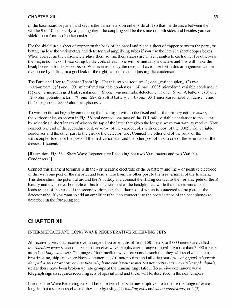
of the base board or panel, and secure the variometers on either side of it so that the distance between themwill be 9 or 10 inches. By so placing them the coupling will be the same on both sides and besides you canshield them from each other easier.
For the shield use a sheet of copper on the back of the panel and place a sheet of copper between the parts, orbetter, enclose the variometers and detector and amplifying tubes if you use the latter in sheet copper boxes.When you set up the variometers place them so that their stators are at right angles to each other for otherwisethe magnetic lines of force set up by the coils of each one will be mutually inductive and this will make theheadphones or loud speaker howl. Whatever tendency the receptor has to howl with this arrangement can beovercome by putting in a grid leak of the right resistance and adjusting the condenser.
The Parts and How to Connect Them Up.--For this set you require: (1) one _variocoupler_; (2) two_variometers_; (3) one _.001 microfarad variable condenser_; (4) one _.0005 microfarad variable condenser_;(5) one _2 megohm grid leak resistance_; (6) one _vacuum tube detector_; (7) one _6 volt A battery_; (8) one_200 ohm potentiometer_; (9) one _22-1/2 volt B battery_; (10) one _.001 microfarad fixed condenser_, and(11) one pair of _2,000 ohm headphones_.
To wire up the set begin by connecting the leading-in wire to the fixed end of the primary coil, or stator, ofthe variocoupler, as shown in Fig. 56, and connect one post of the .001 mfd. variable condenser to the statorby soldering a short length of wire to the tap of the latter that gives the longest wave you want to receive. Nowconnect one end of the secondary coil, or rotor, of the variocoupler with one post of the .0005 mfd. variablecondenser and the other part to the grid of the detector tube. Connect the other end of the rotor of thevariocoupler to one of the posts of the first variometer and the other post of this to one of the terminals of thedetector filament.
[Illustration: Fig. 56.--Short Wave Regenerative Receiving Set (two Variometers and two VariableCondensers.)]
Connect this filament terminal with the - or negative electrode of the A battery and the + or positive electrodeof this with one post of the rheostat and lead a wire from the other post to the free terminal of the filament.This done shunt the potential around the A battery and connect the sliding contact to the - or zinc pole of the Bbattery and the + or carbon pole of this to one terminal of the headphones, while the other terminal of thisleads to one of the posts of the second variometer, the other post of which is connected to the plate of thedetector tube. If you want to add an amplifier tube then connect it to the posts instead of the headphones asdescribed in the foregoing set.
CHAPTER XII
INTERMEDIATE AND LONG WAVE REGENERATIVE RECEIVING SETS
All receiving sets that receive over a range of wave lengths of from 150 meters to 3,000 meters are calledintermediate wave sets and all sets that receive wave lengths over a range of anything more than 3,000 metersare called long wave sets. The range of intermediate wave receptors is such that they will receive amateur,broadcasting, ship and shore Navy, commercial, Arlington's time and all other stations using spark telegraphdamped waves or arc or vacuum tube telephone continuous waves but not continuous wave telegraph signals,unless these have been broken up into groups at the transmitting station. To receive continuous wavetelegraph signals requires receiving sets of special kind and these will be described in the next chapter.
Intermediate Wave Receiving Sets.--There are two chief schemes employed to increase the range of wavelengths that a set can receive and these are by using: (1) loading coils and shunt condensers, and (2)
CHAPTER XII 53
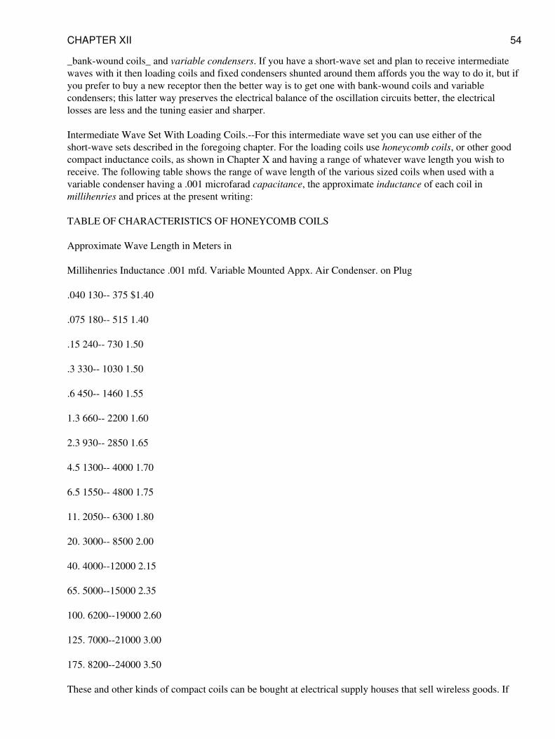
_bank-wound coils_ and variable condensers. If you have a short-wave set and plan to receive intermediatewaves with it then loading coils and fixed condensers shunted around them affords you the way to do it, but ifyou prefer to buy a new receptor then the better way is to get one with bank-wound coils and variablecondensers; this latter way preserves the electrical balance of the oscillation circuits better, the electricallosses are less and the tuning easier and sharper.
Intermediate Wave Set With Loading Coils.--For this intermediate wave set you can use either of theshort-wave sets described in the foregoing chapter. For the loading coils use honeycomb coils, or other goodcompact inductance coils, as shown in Chapter X and having a range of whatever wave length you wish toreceive. The following table shows the range of wave length of the various sized coils when used with avariable condenser having a .001 microfarad capacitance, the approximate inductance of each coil inmillihenries and prices at the present writing:
TABLE OF CHARACTERISTICS OF HONEYCOMB COILS
Approximate Wave Length in Meters in
Millihenries Inductance .001 mfd. Variable Mounted Appx. Air Condenser. on Plug
.040 130-- 375 $1.40
.075 180-- 515 1.40
.15 240-- 730 1.50
.3 330-- 1030 1.50
.6 450-- 1460 1.55
1.3 660-- 2200 1.60
2.3 930-- 2850 1.65
4.5 1300-- 4000 1.70
6.5 1550-- 4800 1.75
11. 2050-- 6300 1.80
20. 3000-- 8500 2.00
40. 4000--12000 2.15
65. 5000--15000 2.35
100. 6200--19000 2.60
125. 7000--21000 3.00
175. 8200--24000 3.50
These and other kinds of compact coils can be bought at electrical supply houses that sell wireless goods. If
CHAPTER XII 54
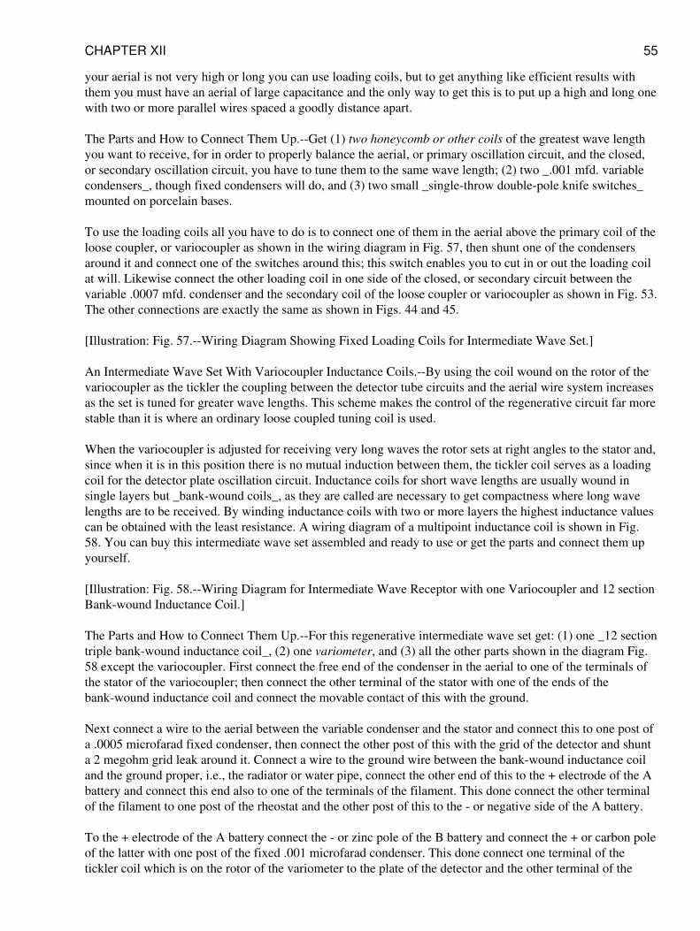
your aerial is not very high or long you can use loading coils, but to get anything like efficient results withthem you must have an aerial of large capacitance and the only way to get this is to put up a high and long onewith two or more parallel wires spaced a goodly distance apart.
The Parts and How to Connect Them Up.--Get (1) two honeycomb or other coils of the greatest wave lengthyou want to receive, for in order to properly balance the aerial, or primary oscillation circuit, and the closed,or secondary oscillation circuit, you have to tune them to the same wave length; (2) two _.001 mfd. variablecondensers_, though fixed condensers will do, and (3) two small _single-throw double-pole knife switches_mounted on porcelain bases.
To use the loading coils all you have to do is to connect one of them in the aerial above the primary coil of theloose coupler, or variocoupler as shown in the wiring diagram in Fig. 57, then shunt one of the condensersaround it and connect one of the switches around this; this switch enables you to cut in or out the loading coilat will. Likewise connect the other loading coil in one side of the closed, or secondary circuit between thevariable .0007 mfd. condenser and the secondary coil of the loose coupler or variocoupler as shown in Fig. 53.The other connections are exactly the same as shown in Figs. 44 and 45.
[Illustration: Fig. 57.--Wiring Diagram Showing Fixed Loading Coils for Intermediate Wave Set.]
An Intermediate Wave Set With Variocoupler Inductance Coils.--By using the coil wound on the rotor of thevariocoupler as the tickler the coupling between the detector tube circuits and the aerial wire system increasesas the set is tuned for greater wave lengths. This scheme makes the control of the regenerative circuit far morestable than it is where an ordinary loose coupled tuning coil is used.
When the variocoupler is adjusted for receiving very long waves the rotor sets at right angles to the stator and,since when it is in this position there is no mutual induction between them, the tickler coil serves as a loadingcoil for the detector plate oscillation circuit. Inductance coils for short wave lengths are usually wound insingle layers but _bank-wound coils_, as they are called are necessary to get compactness where long wavelengths are to be received. By winding inductance coils with two or more layers the highest inductance valuescan be obtained with the least resistance. A wiring diagram of a multipoint inductance coil is shown in Fig.58. You can buy this intermediate wave set assembled and ready to use or get the parts and connect them upyourself.
[Illustration: Fig. 58.--Wiring Diagram for Intermediate Wave Receptor with one Variocoupler and 12 sectionBank-wound Inductance Coil.]
The Parts and How to Connect Them Up.--For this regenerative intermediate wave set get: (1) one _12 sectiontriple bank-wound inductance coil_, (2) one variometer, and (3) all the other parts shown in the diagram Fig.58 except the variocoupler. First connect the free end of the condenser in the aerial to one of the terminals ofthe stator of the variocoupler; then connect the other terminal of the stator with one of the ends of thebank-wound inductance coil and connect the movable contact of this with the ground.
Next connect a wire to the aerial between the variable condenser and the stator and connect this to one post ofa .0005 microfarad fixed condenser, then connect the other post of this with the grid of the detector and shunta 2 megohm grid leak around it. Connect a wire to the ground wire between the bank-wound inductance coiland the ground proper, i.e., the radiator or water pipe, connect the other end of this to the + electrode of the Abattery and connect this end also to one of the terminals of the filament. This done connect the other terminalof the filament to one post of the rheostat and the other post of this to the - or negative side of the A battery.
To the + electrode of the A battery connect the - or zinc pole of the B battery and connect the + or carbon poleof the latter with one post of the fixed .001 microfarad condenser. This done connect one terminal of thetickler coil which is on the rotor of the variometer to the plate of the detector and the other terminal of the
CHAPTER XII 55
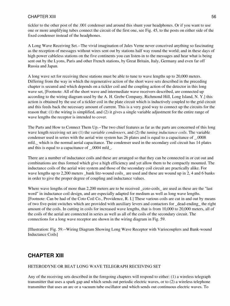
tickler to the other post of the .001 condenser and around this shunt your headphones. Or if you want to useone or more amplifying tubes connect the circuit of the first one, see Fig. 45, to the posts on either side of thefixed condenser instead of the headphones.
A Long Wave Receiving Set.--The vivid imagination of Jules Verne never conceived anything so fascinatingas the reception of messages without wires sent out by stations half way round the world; and in these days ofhigh power cableless stations on the five continents you can listen-in to the messages and hear what is beingsent out by the Lyons, Paris and other French stations, by Great Britain, Italy, Germany and even far offRussia and Japan.
A long wave set for receiving these stations must be able to tune to wave lengths up to 20,000 meters.Differing from the way in which the regenerative action of the short wave sets described in the precedingchapter is secured and which depends on a tickler coil and the coupling action of the detector in this longwave set, [Footnote: All of the short wave and intermediate wave receivers described, are connected upaccording to the wiring diagram used by the A. H. Grebe Company, Richmond Hill, Long Island, N. Y.] thisaction is obtained by the use of a tickler coil in the plate circuit which is inductively coupled to the grid circuitand this feeds back the necessary amount of current. This is a very good way to connect up the circuits for thereason that: (1) the wiring is simplified, and (2) it gives a single variable adjustment for the entire range ofwave lengths the receptor is intended to cover.
The Parts and How to Connect Them Up.--The two chief features as far as the parts are concerned of this longwave length receiving set are (1) the variable condensers, and (2) the tuning inductance coils. The variablecondenser used in series with the aerial wire system has 26 plates and is equal to a capacitance of _.0008mfd._ which is the normal aerial capacitance. The condenser used in the secondary coil circuit has 14 platesand this is equal to a capacitance of _.0004 mfd_.
There are a number of inductance coils and these are arranged so that they can be connected in or cut out andcombinations are thus formed which give a high efficiency and yet allow them to be compactly mounted. Theinductance coils of the aerial wire system and those of the secondary coil circuit are practically alike. Forwave lengths up to 2,200 meters _bank litz-wound coils_ are used and these are wound up in 2, 4 and 6 banksin order to give the proper degree of coupling and inductance values.
Where wave lengths of more than 2,200 meters are to be received _coto-coils_ are used as these are the "lastword" in inductance coil design, and are especially adapted for medium as well as long wave lengths.[Footnote: Can be had of the Coto Coil Co., Providence, R. I.] These various coils are cut in and out by meansof two five-point switches which are provided with auxiliary levers and contactors for _dead-ending_ the rightamount of the coils. In cutting in coils for increased wave lengths, that is from 10,000 to 20,000 meters, all ofthe coils of the aerial are connected in series as well as all of the coils of the secondary circuit. Theconnections for a long wave receptor are shown in the wiring diagram in Fig. 59.
[Illustration: Fig. 59.--Wiring Diagram Showing Long Wave Receptor with Variocouplers and Bank-woundInductance Coils]
CHAPTER XIII
HETERODYNE OR BEAT LONG WAVE TELEGRAPH RECEIVING SET
Any of the receiving sets described in the foregoing chapters will respond to either: (1) a wireless telegraphtransmitter that uses a spark gap and which sends out periodic electric waves, or to (2) a wireless telephonetransmitter that uses an arc or a vacuum tube oscillator and which sends out continuous electric waves. To
CHAPTER XIII 56
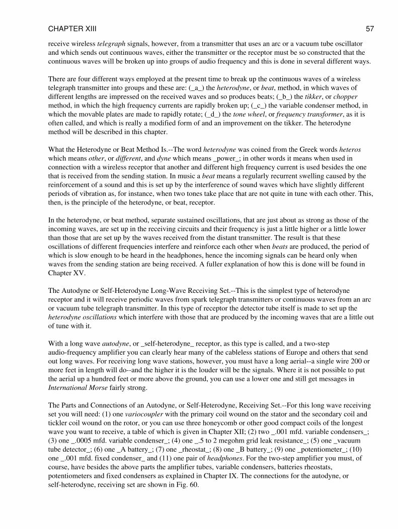
receive wireless telegraph signals, however, from a transmitter that uses an arc or a vacuum tube oscillatorand which sends out continuous waves, either the transmitter or the receptor must be so constructed that thecontinuous waves will be broken up into groups of audio frequency and this is done in several different ways.
There are four different ways employed at the present time to break up the continuous waves of a wirelesstelegraph transmitter into groups and these are: (_a_) the heterodyne, or beat, method, in which waves ofdifferent lengths are impressed on the received waves and so produces beats; (_b_) the tikker, or choppermethod, in which the high frequency currents are rapidly broken up; (_c_) the variable condenser method, inwhich the movable plates are made to rapidly rotate; (_d_) the tone wheel, or frequency transformer, as it isoften called, and which is really a modified form of and an improvement on the tikker. The heterodynemethod will be described in this chapter.
What the Heterodyne or Beat Method Is.--The word heterodyne was coined from the Greek words heteroswhich means other, or different, and dyne which means _power_; in other words it means when used inconnection with a wireless receptor that another and different high frequency current is used besides the onethat is received from the sending station. In music a beat means a regularly recurrent swelling caused by thereinforcement of a sound and this is set up by the interference of sound waves which have slightly differentperiods of vibration as, for instance, when two tones take place that are not quite in tune with each other. This,then, is the principle of the heterodyne, or beat, receptor.
In the heterodyne, or beat method, separate sustained oscillations, that are just about as strong as those of theincoming waves, are set up in the receiving circuits and their frequency is just a little higher or a little lowerthan those that are set up by the waves received from the distant transmitter. The result is that theseoscillations of different frequencies interfere and reinforce each other when beats are produced, the period ofwhich is slow enough to be heard in the headphones, hence the incoming signals can be heard only whenwaves from the sending station are being received. A fuller explanation of how this is done will be found inChapter XV.
The Autodyne or Self-Heterodyne Long-Wave Receiving Set.--This is the simplest type of heterodynereceptor and it will receive periodic waves from spark telegraph transmitters or continuous waves from an arcor vacuum tube telegraph transmitter. In this type of receptor the detector tube itself is made to set up theheterodyne oscillations which interfere with those that are produced by the incoming waves that are a little outof tune with it.
With a long wave autodyne, or _self-heterodyne_ receptor, as this type is called, and a two-stepaudio-frequency amplifier you can clearly hear many of the cableless stations of Europe and others that sendout long waves. For receiving long wave stations, however, you must have a long aerial--a single wire 200 ormore feet in length will do--and the higher it is the louder will be the signals. Where it is not possible to putthe aerial up a hundred feet or more above the ground, you can use a lower one and still get messages inInternational Morse fairly strong.
The Parts and Connections of an Autodyne, or Self-Heterodyne, Receiving Set.--For this long wave receivingset you will need: (1) one variocoupler with the primary coil wound on the stator and the secondary coil andtickler coil wound on the rotor, or you can use three honeycomb or other good compact coils of the longestwave you want to receive, a table of which is given in Chapter XII; (2) two _.001 mfd. variable condensers_;(3) one _.0005 mfd. variable condenser_; (4) one _.5 to 2 megohm grid leak resistance_; (5) one _vacuumtube detector_; (6) one _A battery_; (7) one _rheostat_; (8) one _B battery_; (9) one _potentiometer_; (10)one _.001 mfd. fixed condenser_ and (11) one pair of headphones. For the two-step amplifier you must, ofcourse, have besides the above parts the amplifier tubes, variable condensers, batteries rheostats,potentiometers and fixed condensers as explained in Chapter IX. The connections for the autodyne, orself-heterodyne, receiving set are shown in Fig. 60.
CHAPTER XIII 57
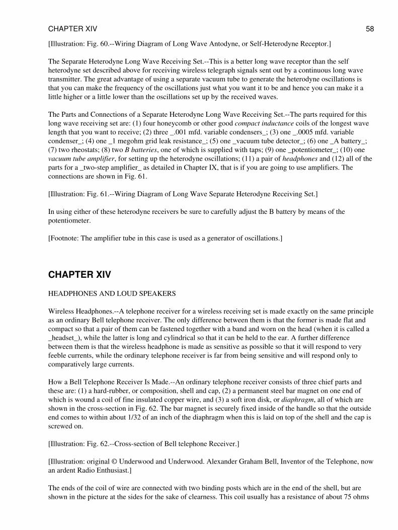
[Illustration: Fig. 60.--Wiring Diagram of Long Wave Antodyne, or Self-Heterodyne Receptor.]
The Separate Heterodyne Long Wave Receiving Set.--This is a better long wave receptor than the selfheterodyne set described above for receiving wireless telegraph signals sent out by a continuous long wavetransmitter. The great advantage of using a separate vacuum tube to generate the heterodyne oscillations isthat you can make the frequency of the oscillations just what you want it to be and hence you can make it alittle higher or a little lower than the oscillations set up by the received waves.
The Parts and Connections of a Separate Heterodyne Long Wave Receiving Set.--The parts required for thislong wave receiving set are: (1) four honeycomb or other good compact inductance coils of the longest wavelength that you want to receive; (2) three _.001 mfd. variable condensers_; (3) one _.0005 mfd. variablecondenser_; (4) one _1 megohm grid leak resistance_; (5) one _vacuum tube detector_; (6) one _A battery_;(7) two rheostats; (8) two B batteries, one of which is supplied with taps; (9) one _potentiometer_; (10) onevacuum tube amplifier, for setting up the heterodyne oscillations; (11) a pair of headphones and (12) all of theparts for a _two-step amplifier_ as detailed in Chapter IX, that is if you are going to use amplifiers. Theconnections are shown in Fig. 61.
[Illustration: Fig. 61.--Wiring Diagram of Long Wave Separate Heterodyne Receiving Set.]
In using either of these heterodyne receivers be sure to carefully adjust the B battery by means of thepotentiometer.
[Footnote: The amplifier tube in this case is used as a generator of oscillations.]
CHAPTER XIV
HEADPHONES AND LOUD SPEAKERS
Wireless Headphones.--A telephone receiver for a wireless receiving set is made exactly on the same principleas an ordinary Bell telephone receiver. The only difference between them is that the former is made flat andcompact so that a pair of them can be fastened together with a band and worn on the head (when it is called a_headset_), while the latter is long and cylindrical so that it can be held to the ear. A further differencebetween them is that the wireless headphone is made as sensitive as possible so that it will respond to veryfeeble currents, while the ordinary telephone receiver is far from being sensitive and will respond only tocomparatively large currents.
How a Bell Telephone Receiver Is Made.--An ordinary telephone receiver consists of three chief parts andthese are: (1) a hard-rubber, or composition, shell and cap, (2) a permanent steel bar magnet on one end ofwhich is wound a coil of fine insulated copper wire, and (3) a soft iron disk, or diaphragm, all of which areshown in the cross-section in Fig. 62. The bar magnet is securely fixed inside of the handle so that the outsideend comes to within about 1/32 of an inch of the diaphragm when this is laid on top of the shell and the cap isscrewed on.
[Illustration: Fig. 62.--Cross-section of Bell telephone Receiver.]
[Illustration: original © Underwood and Underwood. Alexander Graham Bell, Inventor of the Telephone, nowan ardent Radio Enthusiast.]
The ends of the coil of wire are connected with two binding posts which are in the end of the shell, but areshown in the picture at the sides for the sake of clearness. This coil usually has a resistance of about 75 ohms
CHAPTER XIV 58
and the meaning of the ohmic resistance of a receiver and its bearing on the sensitiveness of it will beexplained a little farther along. After the disk, or diaphragm, which is generally made of thin, soft sheet ironthat has been tinned or japanned, [Footnote: A disk of photographic tin-type plate is generally used.] is placedover the end of the magnet, the cap, which has a small opening in it, is screwed on and the receiver is ready touse.
How a Wireless Headphone Is Made.--For wireless work a receiver of the watch-case type is used and nearlyalways two such receivers are connected with a headband. It consists of a permanent bar magnet bent so that itwill fit into the shell of the receiver as shown at A in Fig. 63.
[Illustration: Fig. 63.--Wireless Headphone.]
The ends of this magnet, which are called poles, are bent up, and hence this type is called a bipolar receiver.The magnets are wound with fine insulated wire as before and the diaphragm is held securely in place overthem by screwing on the cap.
About Resistance, Turns of Wire and Sensitivity of Headphones.--If you are a beginner in wireless you willhear those who are experienced speak of a telephone receiver as having a resistance of 75 ohms, 1,000 ohms,2,000 or 3,000 ohms, as the case may be; from this you will gather that the higher the resistance of the wire onthe magnets the more sensitive the receiver is. In a sense this is true, but it is not the resistance of the magnetcoils that makes it sensitive, in fact, it cuts down the current, but it is the number of turns of wire on them thatdetermines its sensitiveness; it is easy to see that this is so, for the larger the number of turns the more oftenwill the same current flow round the cores of the magnet and so magnetize them to a greater extent.
But to wind a large number of turns of wire close enough to the cores to be effective the wire must be verysmall and so, of course, the higher the resistance will be. Now the wire used for winding good receivers isusually No. 40, and this has a diameter of .0031 inch; consequently, when you know the ohmic resistance youget an idea of the number of turns of wire and from this you gather in a general way what the sensitivity of thereceiver is.
A receiver that is sensitive enough for wireless work should be wound to not less than 1,000 ohms (this meanseach ear phone), while those of a better grade are wound to as high as 3,000 ohms for each one. A high-gradeheadset is shown in Fig. 64. Each phone of a headset should be wound to the same resistance, and these areconnected in series as shown. Where two or more headsets are used with one wireless receiving set they mustall be of the same resistance and connected in series, that is, the coils of one head set are connected with thecoils of the next head set and so on to form a continuous circuit.
[Illustration: Fig. 64.--Wireless Headphone.]
The Impedance of Headphones.--When a current is flowing through a circuit the material of which the wire ismade not only opposes its passage--this is called its _ohmic resistance_--but a _counter-electromotive force_to the current is set up due to the inductive effects of the current on itself and this is called impedance. Wherea wire is wound in a coil the impedance of the circuit is increased and where an alternating current is used theimpedance grows greater as the frequency gets higher. The impedance of the magnet coils of a receiver is sogreat for high frequency oscillations that the latter cannot pass through them; in other words, they are chokedoff.
How the Headphones Work.--As you will see from the cross-sections in Figs. 62 and 63 there is noconnection, electrical or mechanical, between the diaphragm and the other parts of the receiver. Now wheneither feeble oscillations, which have been rectified by a detector, or small currents from a B battery, flowthrough the magnet coils the permanent steel magnet is energized to a greater extent than when no current isflowing through it. This added magnetic energy makes the magnet attract the diaphragm more than it would
CHAPTER XIV 59
do by its own force. If, on the other hand, the current is cut off the pull of the magnet is lessened and as itsattraction for the diaphragm is decreased the latter springs back to its original position. When varying currentsflow through the coils the diaphragm vibrates accordingly and sends out sound waves.
About Loud Speakers.--The simplest acoustic instrument ever invented is the megaphone, which latter is aGreek word meaning great sound. It is a very primitive device and our Indians made it out of birch-barkbefore Columbus discovered America. In its simplest form it consists of a cone-shaped horn and as thespeaker talks into the small end the concentrated sound waves pass out of the large end in whatever directionit is held.
Now a loud speaker of whatever kind consists of two chief parts and these are: (1) a telephone receiver, and(2) a megaphone, or horn as it is called. A loud speaker when connected with a wireless receiving set makes itpossible for a room, or an auditorium, full of people, or an outdoor crowd, to hear what is being sent out by adistant station instead of being limited to a few persons listening-in with headphones. To use a loud speakeryou should have a vacuum tube detector receiving set and this must be provided with a one-step amplifier atleast.
To get really good results you need a two-step amplifier and then energize the plate of the second vacuumtube amplifier with a 100 volt B battery; or if you have a three-step amplifier then use the high voltage on theplate of the third amplifier tube. Amplifying tubes are made to stand a plate potential of 100 volts and this isthe kind you must use. Now it may seem curious, but when the current flows through the coils of thetelephone receiver in one direction it gives better results than when it flows through in the other direction; tofind out the way the current gives the best results try it out both ways and this you can do by simply reversingthe connections.
The Simplest Type of Loud Speaker.--This loud speaker, which is called, the Arkay, [Footnote: Made by theRiley-Klotz Mfg. Co., Newark, N. J.] will work on a one- or two-step amplifier. It consists of a brass hornwith a curve in it and in the bottom there is an adapter, or frame, with a set screw in it so that you can fit inone of your headphones and this is all there is to it. The construction is rigid enough to prevent overtones, ordistortion of speech or music. It is shown in Fig. 65.
[Illustration: Fig. 65.--Arkay Loud Speaker.]
Another Simple Kind of Loud Speaker.--Another loud speaker, see Fig. 66, is known as the Amplitone[Footnote: Made by the American Pattern, Foundry and Machine Co., 82 Church Street, N. Y. C.] and itlikewise makes use of the headphones as the sound producer. This device has a cast metal horn whichimproves the quality of the sound, and all you have to do is to slip the headphones on the inlet tubes of thehorn and it is ready for use. The two headphones not only give a longer volume of sound than where a singleone is used but there is a certain blended quality which results from one phone smoothing out theimperfections of the other.
[Illustration: Fig. 66.--Amplitone Loud Speaker.]
A Third Kind of Simple Loud Speaker.--The operation of the Amplitron, [Footnote: Made by the RadioService Co., 110 W. 40th Street, N. Y.] as this loud speaker is called, is slightly different from others used forthe same purpose. The sounds set up by the headphone are conveyed to the apex of an inverted copper conewhich is 7 inches long and 10 inches in diameter. Here it is reflected by a parabolic mirror which greatlyamplifies the sounds. The amplification takes place without distortion, the sounds remaining as clear and crispas when projected by the transmitting station. By removing the cap from the receiver the shell is screwed intoa receptacle on the end of the loud speaker and the instrument is ready for use. It is pictured in Fig. 67.
[Illustration: Fig. 67.--Amplitron Loud Speaker.]
CHAPTER XIV 60
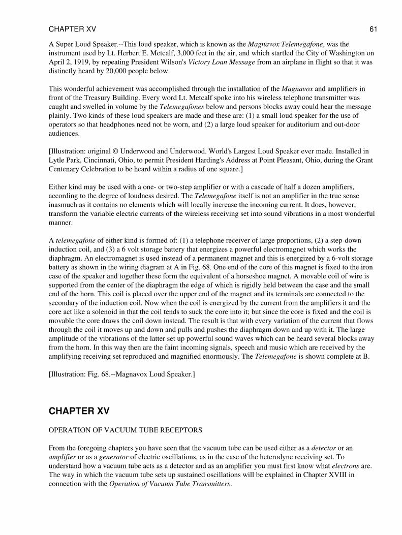
A Super Loud Speaker.--This loud speaker, which is known as the Magnavox Telemegafone, was theinstrument used by Lt. Herbert E. Metcalf, 3,000 feet in the air, and which startled the City of Washington onApril 2, 1919, by repeating President Wilson's Victory Loan Message from an airplane in flight so that it wasdistinctly heard by 20,000 people below.
This wonderful achievement was accomplished through the installation of the Magnavox and amplifiers infront of the Treasury Building. Every word Lt. Metcalf spoke into his wireless telephone transmitter wascaught and swelled in volume by the Telemegafones below and persons blocks away could hear the messageplainly. Two kinds of these loud speakers are made and these are: (1) a small loud speaker for the use ofoperators so that headphones need not be worn, and (2) a large loud speaker for auditorium and out-dooraudiences.
[Illustration: original © Underwood and Underwood. World's Largest Loud Speaker ever made. Installed inLytle Park, Cincinnati, Ohio, to permit President Harding's Address at Point Pleasant, Ohio, during the GrantCentenary Celebration to be heard within a radius of one square.]
Either kind may be used with a one- or two-step amplifier or with a cascade of half a dozen amplifiers,according to the degree of loudness desired. The Telemegafone itself is not an amplifier in the true senseinasmuch as it contains no elements which will locally increase the incoming current. It does, however,transform the variable electric currents of the wireless receiving set into sound vibrations in a most wonderfulmanner.
A telemegafone of either kind is formed of: (1) a telephone receiver of large proportions, (2) a step-downinduction coil, and (3) a 6 volt storage battery that energizes a powerful electromagnet which works thediaphragm. An electromagnet is used instead of a permanent magnet and this is energized by a 6-volt storagebattery as shown in the wiring diagram at A in Fig. 68. One end of the core of this magnet is fixed to the ironcase of the speaker and together these form the equivalent of a horseshoe magnet. A movable coil of wire issupported from the center of the diaphragm the edge of which is rigidly held between the case and the smallend of the horn. This coil is placed over the upper end of the magnet and its terminals are connected to thesecondary of the induction coil. Now when the coil is energized by the current from the amplifiers it and thecore act like a solenoid in that the coil tends to suck the core into it; but since the core is fixed and the coil ismovable the core draws the coil down instead. The result is that with every variation of the current that flowsthrough the coil it moves up and down and pulls and pushes the diaphragm down and up with it. The largeamplitude of the vibrations of the latter set up powerful sound waves which can be heard several blocks awayfrom the horn. In this way then are the faint incoming signals, speech and music which are received by theamplifying receiving set reproduced and magnified enormously. The Telemegafone is shown complete at B.
[Illustration: Fig. 68.--Magnavox Loud Speaker.]
CHAPTER XV
OPERATION OF VACUUM TUBE RECEPTORS
From the foregoing chapters you have seen that the vacuum tube can be used either as a detector or anamplifier or as a generator of electric oscillations, as in the case of the heterodyne receiving set. Tounderstand how a vacuum tube acts as a detector and as an amplifier you must first know what electrons are.The way in which the vacuum tube sets up sustained oscillations will be explained in Chapter XVIII inconnection with the Operation of Vacuum Tube Transmitters.
CHAPTER XV 61
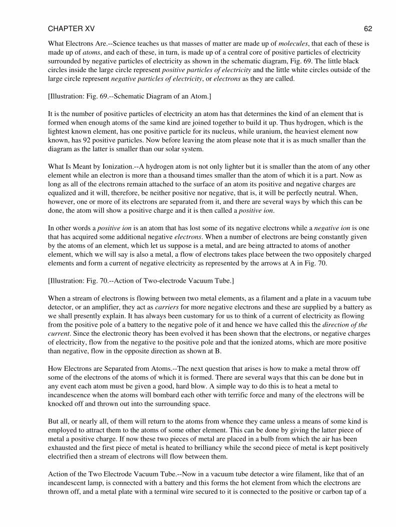
What Electrons Are.--Science teaches us that masses of matter are made up of molecules, that each of these ismade up of atoms, and each of these, in turn, is made up of a central core of positive particles of electricitysurrounded by negative particles of electricity as shown in the schematic diagram, Fig. 69. The little blackcircles inside the large circle represent positive particles of electricity and the little white circles outside of thelarge circle represent negative particles of electricity, or electrons as they are called.
[Illustration: Fig. 69.--Schematic Diagram of an Atom.]
It is the number of positive particles of electricity an atom has that determines the kind of an element that isformed when enough atoms of the same kind are joined together to build it up. Thus hydrogen, which is thelightest known element, has one positive particle for its nucleus, while uranium, the heaviest element nowknown, has 92 positive particles. Now before leaving the atom please note that it is as much smaller than thediagram as the latter is smaller than our solar system.
What Is Meant by Ionization.--A hydrogen atom is not only lighter but it is smaller than the atom of any otherelement while an electron is more than a thousand times smaller than the atom of which it is a part. Now aslong as all of the electrons remain attached to the surface of an atom its positive and negative charges areequalized and it will, therefore, be neither positive nor negative, that is, it will be perfectly neutral. When,however, one or more of its electrons are separated from it, and there are several ways by which this can bedone, the atom will show a positive charge and it is then called a positive ion.
In other words a positive ion is an atom that has lost some of its negative electrons while a negative ion is onethat has acquired some additional negative electrons. When a number of electrons are being constantly givenby the atoms of an element, which let us suppose is a metal, and are being attracted to atoms of anotherelement, which we will say is also a metal, a flow of electrons takes place between the two oppositely chargedelements and form a current of negative electricity as represented by the arrows at A in Fig. 70.
[Illustration: Fig. 70.--Action of Two-electrode Vacuum Tube.]
When a stream of electrons is flowing between two metal elements, as a filament and a plate in a vacuum tubedetector, or an amplifier, they act as carriers for more negative electrons and these are supplied by a battery aswe shall presently explain. It has always been customary for us to think of a current of electricity as flowingfrom the positive pole of a battery to the negative pole of it and hence we have called this the direction of thecurrent. Since the electronic theory has been evolved it has been shown that the electrons, or negative chargesof electricity, flow from the negative to the positive pole and that the ionized atoms, which are more positivethan negative, flow in the opposite direction as shown at B.
How Electrons are Separated from Atoms.--The next question that arises is how to make a metal throw offsome of the electrons of the atoms of which it is formed. There are several ways that this can be done but inany event each atom must be given a good, hard blow. A simple way to do this is to heat a metal toincandescence when the atoms will bombard each other with terrific force and many of the electrons will beknocked off and thrown out into the surrounding space.
But all, or nearly all, of them will return to the atoms from whence they came unless a means of some kind isemployed to attract them to the atoms of some other element. This can be done by giving the latter piece ofmetal a positive charge. If now these two pieces of metal are placed in a bulb from which the air has beenexhausted and the first piece of metal is heated to brilliancy while the second piece of metal is kept positivelyelectrified then a stream of electrons will flow between them.
Action of the Two Electrode Vacuum Tube.--Now in a vacuum tube detector a wire filament, like that of anincandescent lamp, is connected with a battery and this forms the hot element from which the electrons arethrown off, and a metal plate with a terminal wire secured to it is connected to the positive or carbon tap of a
CHAPTER XV 62
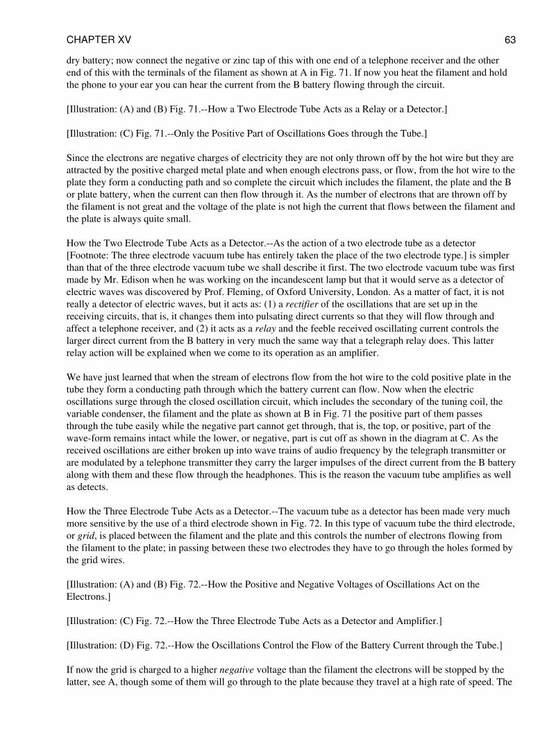
dry battery; now connect the negative or zinc tap of this with one end of a telephone receiver and the otherend of this with the terminals of the filament as shown at A in Fig. 71. If now you heat the filament and holdthe phone to your ear you can hear the current from the B battery flowing through the circuit.
[Illustration: (A) and (B) Fig. 71.--How a Two Electrode Tube Acts as a Relay or a Detector.]
[Illustration: (C) Fig. 71.--Only the Positive Part of Oscillations Goes through the Tube.]
Since the electrons are negative charges of electricity they are not only thrown off by the hot wire but they areattracted by the positive charged metal plate and when enough electrons pass, or flow, from the hot wire to theplate they form a conducting path and so complete the circuit which includes the filament, the plate and the Bor plate battery, when the current can then flow through it. As the number of electrons that are thrown off bythe filament is not great and the voltage of the plate is not high the current that flows between the filament andthe plate is always quite small.
How the Two Electrode Tube Acts as a Detector.--As the action of a two electrode tube as a detector[Footnote: The three electrode vacuum tube has entirely taken the place of the two electrode type.] is simplerthan that of the three electrode vacuum tube we shall describe it first. The two electrode vacuum tube was firstmade by Mr. Edison when he was working on the incandescent lamp but that it would serve as a detector ofelectric waves was discovered by Prof. Fleming, of Oxford University, London. As a matter of fact, it is notreally a detector of electric waves, but it acts as: (1) a rectifier of the oscillations that are set up in thereceiving circuits, that is, it changes them into pulsating direct currents so that they will flow through andaffect a telephone receiver, and (2) it acts as a relay and the feeble received oscillating current controls thelarger direct current from the B battery in very much the same way that a telegraph relay does. This latterrelay action will be explained when we come to its operation as an amplifier.
We have just learned that when the stream of electrons flow from the hot wire to the cold positive plate in thetube they form a conducting path through which the battery current can flow. Now when the electricoscillations surge through the closed oscillation circuit, which includes the secondary of the tuning coil, thevariable condenser, the filament and the plate as shown at B in Fig. 71 the positive part of them passesthrough the tube easily while the negative part cannot get through, that is, the top, or positive, part of thewave-form remains intact while the lower, or negative, part is cut off as shown in the diagram at C. As thereceived oscillations are either broken up into wave trains of audio frequency by the telegraph transmitter orare modulated by a telephone transmitter they carry the larger impulses of the direct current from the B batteryalong with them and these flow through the headphones. This is the reason the vacuum tube amplifies as wellas detects.
How the Three Electrode Tube Acts as a Detector.--The vacuum tube as a detector has been made very muchmore sensitive by the use of a third electrode shown in Fig. 72. In this type of vacuum tube the third electrode,or grid, is placed between the filament and the plate and this controls the number of electrons flowing fromthe filament to the plate; in passing between these two electrodes they have to go through the holes formed bythe grid wires.
[Illustration: (A) and (B) Fig. 72.--How the Positive and Negative Voltages of Oscillations Act on theElectrons.]
[Illustration: (C) Fig. 72.--How the Three Electrode Tube Acts as a Detector and Amplifier.]
[Illustration: (D) Fig. 72.--How the Oscillations Control the Flow of the Battery Current through the Tube.]
If now the grid is charged to a higher negative voltage than the filament the electrons will be stopped by thelatter, see A, though some of them will go through to the plate because they travel at a high rate of speed. The
CHAPTER XV 63
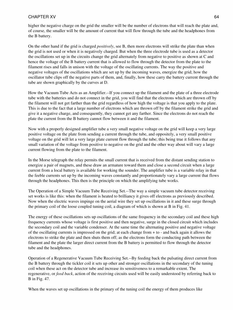
higher the negative charge on the grid the smaller will be the number of electrons that will reach the plate and,of course, the smaller will be the amount of current that will flow through the tube and the headphones fromthe B battery.
On the other hand if the grid is charged positively, see B, then more electrons will strike the plate than whenthe grid is not used or when it is negatively charged. But when the three electrode tube is used as a detectorthe oscillations set up in the circuits change the grid alternately from negative to positive as shown at C andhence the voltage of the B battery current that is allowed to flow through the detector from the plate to thefilament rises and falls in unison with the voltage of the oscillating currents. The way the positive andnegative voltages of the oscillations which are set up by the incoming waves, energize the grid; how theoscillator tube clips off the negative parts of them, and, finally, how these carry the battery current through thetube are shown graphically by the curves at D.
How the Vacuum Tube Acts as an Amplifier.--If you connect up the filament and the plate of a three electrodetube with the batteries and do not connect in the grid, you will find that the electrons which are thrown off bythe filament will not get farther than the grid regardless of how high the voltage is that you apply to the plate.This is due to the fact that a large number of electrons which are thrown off by the filament strike the grid andgive it a negative charge, and consequently, they cannot get any farther. Since the electrons do not reach theplate the current from the B battery cannot flow between it and the filament.
Now with a properly designed amplifier tube a very small negative voltage on the grid will keep a very largepositive voltage on the plate from sending a current through the tube, and oppositely, a very small positivevoltage on the grid will let a very large plate current flow through the tube; this being true it follows that anysmall variation of the voltage from positive to negative on the grid and the other way about will vary a largecurrent flowing from the plate to the filament.
In the Morse telegraph the relay permits the small current that is received from the distant sending station toenergize a pair of magnets, and these draw an armature toward them and close a second circuit when a largecurrent from a local battery is available for working the sounder. The amplifier tube is a variable relay in thatthe feeble currents set up by the incoming waves constantly and proportionately vary a large current that flowsthrough the headphones. This then is the principle on which the amplifying tube works.
The Operation of a Simple Vacuum Tube Receiving Set.--The way a simple vacuum tube detector receivingset works is like this: when the filament is heated to brilliancy it gives off electrons as previously described.Now when the electric waves impinge on the aerial wire they set up oscillations in it and these surge throughthe primary coil of the loose coupled tuning coil, a diagram of which is shown at B in Fig. 41.
The energy of these oscillations sets up oscillations of the same frequency in the secondary coil and these highfrequency currents whose voltage is first positive and then negative, surge in the closed circuit which includesthe secondary coil and the variable condenser. At the same time the alternating positive and negative voltageof the oscillating currents is impressed on the grid; at each change from + to - and back again it allows theelectrons to strike the plate and then shuts them off; as the electrons form the conducting path between thefilament and the plate the larger direct current from the B battery is permitted to flow through the detectortube and the headphones.
Operation of a Regenerative Vacuum Tube Receiving Set.--By feeding back the pulsating direct current fromthe B battery through the tickler coil it sets up other and stronger oscillations in the secondary of the tuningcoil when these act on the detector tube and increase its sensitiveness to a remarkable extent. Theregenerative, or feed back, action of the receiving circuits used will be easily understood by referring back toB in Fig. 47.
When the waves set up oscillations in the primary of the tuning coil the energy of them produces like
CHAPTER XV 64
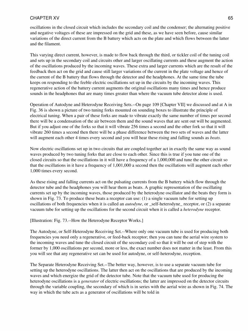
oscillations in the closed circuit which includes the secondary coil and the condenser; the alternating positiveand negative voltages of these are impressed on the grid and these, as we have seen before, cause similarvariations of the direct current from the B battery which acts on the plate and which flows between the latterand the filament.
This varying direct current, however, is made to flow back through the third, or tickler coil of the tuning coiland sets up in the secondary coil and circuits other and larger oscillating currents and these augment the actionof the oscillations produced by the incoming waves. These extra and larger currents which are the result of thefeedback then act on the grid and cause still larger variations of the current in the plate voltage and hence ofthe current of the B battery that flows through the detector and the headphones. At the same time the tubekeeps on responding to the feeble electric oscillations set up in the circuits by the incoming waves. Thisregenerative action of the battery current augments the original oscillations many times and hence producesounds in the headphones that are many times greater than where the vacuum tube detector alone is used.
Operation of Autodyne and Heterodyne Receiving Sets.--On page 109 [Chapter VII] we discussed and at A inFig. 36 is shown a picture of two tuning forks mounted on sounding boxes to illustrate the principle ofelectrical tuning. When a pair of these forks are made to vibrate exactly the same number of times per secondthere will be a condensation of the air between them and the sound waves that are sent out will be augmented.But if you adjust one of the forks so that it will vibrate 256 times a second and the other fork so that it willvibrate 260 times a second then there will be a phase difference between the two sets of waves and the latterwill augment each other 4 times every second and you will hear these rising and falling sounds as beats.
Now electric oscillations set up in two circuits that are coupled together act in exactly the same way as soundwaves produced by two tuning forks that are close to each other. Since this is true if you tune one of theclosed circuits so that the oscillations in it will have a frequency of a 1,000,000 and tune the other circuit sothat the oscillations in it have a frequency of 1,001,000 a second then the oscillations will augment each other1,000 times every second.
As these rising and falling currents act on the pulsating currents from the B battery which flow through thedetector tube and the headphones you will hear them as beats. A graphic representation of the oscillatingcurrents set up by the incoming waves, those produced by the heterodyne oscillator and the beats they form isshown in Fig. 73. To produce these beats a receptor can use: (1) a single vacuum tube for setting uposcillations of both frequencies when it is called an autodyne, or _self-heterodyne_ receptor, or (2) a separatevacuum tube for setting up the oscillations for the second circuit when it is called a heterodyne receptor.
[Illustration: Fig. 73.--How the Heterodyne Receptor Works.]
The Autodyne, or Self-Heterodyne Receiving Set.--Where only one vacuum tube is used for producing bothfrequencies you need only a regenerative, or feed-back receptor; then you can tune the aerial wire system tothe incoming waves and tune the closed circuit of the secondary coil so that it will be out of step with theformer by 1,000 oscillations per second, more or less, the exact number does not matter in the least. From thisyou will see that any regenerative set can be used for autodyne, or self-heterodyne, reception.
The Separate Heterodyne Receiving Set.--The better way, however, is to use a separate vacuum tube forsetting up the heterodyne oscillations. The latter then act on the oscillations that are produced by the incomingwaves and which energize the grid of the detector tube. Note that the vacuum tube used for producing theheterodyne oscillations is a generator of electric oscillations; the latter are impressed on the detector circuitsthrough the variable coupling, the secondary of which is in series with the aerial wire as shown in Fig. 74. Theway in which the tube acts as a generator of oscillations will be told in
CHAPTER XV 65
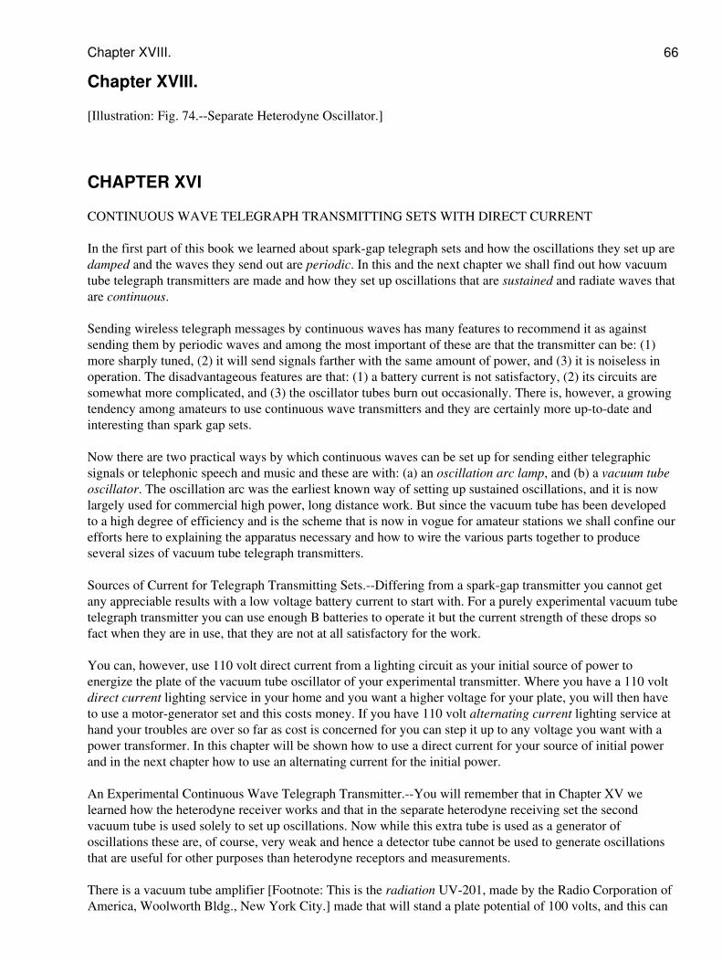
Chapter XVIII.
[Illustration: Fig. 74.--Separate Heterodyne Oscillator.]
CHAPTER XVI
CONTINUOUS WAVE TELEGRAPH TRANSMITTING SETS WITH DIRECT CURRENT
In the first part of this book we learned about spark-gap telegraph sets and how the oscillations they set up aredamped and the waves they send out are periodic. In this and the next chapter we shall find out how vacuumtube telegraph transmitters are made and how they set up oscillations that are sustained and radiate waves thatare continuous.
Sending wireless telegraph messages by continuous waves has many features to recommend it as againstsending them by periodic waves and among the most important of these are that the transmitter can be: (1)more sharply tuned, (2) it will send signals farther with the same amount of power, and (3) it is noiseless inoperation. The disadvantageous features are that: (1) a battery current is not satisfactory, (2) its circuits aresomewhat more complicated, and (3) the oscillator tubes burn out occasionally. There is, however, a growingtendency among amateurs to use continuous wave transmitters and they are certainly more up-to-date andinteresting than spark gap sets.
Now there are two practical ways by which continuous waves can be set up for sending either telegraphicsignals or telephonic speech and music and these are with: (a) an oscillation arc lamp, and (b) a vacuum tubeoscillator. The oscillation arc was the earliest known way of setting up sustained oscillations, and it is nowlargely used for commercial high power, long distance work. But since the vacuum tube has been developedto a high degree of efficiency and is the scheme that is now in vogue for amateur stations we shall confine ourefforts here to explaining the apparatus necessary and how to wire the various parts together to produceseveral sizes of vacuum tube telegraph transmitters.
Sources of Current for Telegraph Transmitting Sets.--Differing from a spark-gap transmitter you cannot getany appreciable results with a low voltage battery current to start with. For a purely experimental vacuum tubetelegraph transmitter you can use enough B batteries to operate it but the current strength of these drops sofact when they are in use, that they are not at all satisfactory for the work.
You can, however, use 110 volt direct current from a lighting circuit as your initial source of power toenergize the plate of the vacuum tube oscillator of your experimental transmitter. Where you have a 110 voltdirect current lighting service in your home and you want a higher voltage for your plate, you will then haveto use a motor-generator set and this costs money. If you have 110 volt alternating current lighting service athand your troubles are over so far as cost is concerned for you can step it up to any voltage you want with apower transformer. In this chapter will be shown how to use a direct current for your source of initial powerand in the next chapter how to use an alternating current for the initial power.
An Experimental Continuous Wave Telegraph Transmitter.--You will remember that in Chapter XV welearned how the heterodyne receiver works and that in the separate heterodyne receiving set the secondvacuum tube is used solely to set up oscillations. Now while this extra tube is used as a generator ofoscillations these are, of course, very weak and hence a detector tube cannot be used to generate oscillationsthat are useful for other purposes than heterodyne receptors and measurements.
There is a vacuum tube amplifier [Footnote: This is the radiation UV-201, made by the Radio Corporation ofAmerica, Woolworth Bldg., New York City.] made that will stand a plate potential of 100 volts, and this can
Chapter XVIII. 66
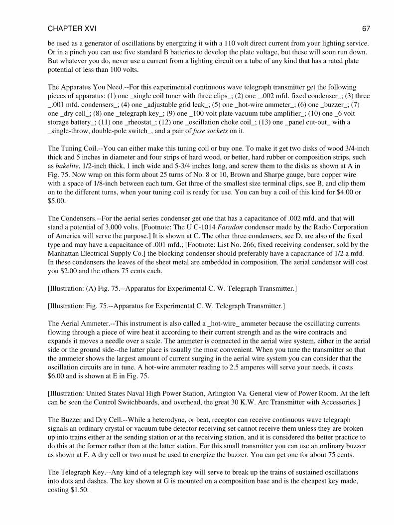
be used as a generator of oscillations by energizing it with a 110 volt direct current from your lighting service.Or in a pinch you can use five standard B batteries to develop the plate voltage, but these will soon run down.But whatever you do, never use a current from a lighting circuit on a tube of any kind that has a rated platepotential of less than 100 volts.
The Apparatus You Need.--For this experimental continuous wave telegraph transmitter get the followingpieces of apparatus: (1) one _single coil tuner with three clips_; (2) one _.002 mfd. fixed condenser_; (3) three_.001 mfd. condensers_; (4) one _adjustable grid leak_; (5) one _hot-wire ammeter_; (6) one _buzzer_; (7)one _dry cell_; (8) one _telegraph key_; (9) one _100 volt plate vacuum tube amplifier_; (10) one _6 voltstorage battery_; (11) one _rheostat_; (12) one _oscillation choke coil_; (13) one _panel cut-out_ with a_single-throw, double-pole switch_, and a pair of fuse sockets on it.
The Tuning Coil.--You can either make this tuning coil or buy one. To make it get two disks of wood 3/4-inchthick and 5 inches in diameter and four strips of hard wood, or better, hard rubber or composition strips, suchas bakelite, 1/2-inch thick, 1 inch wide and 5-3/4 inches long, and screw them to the disks as shown at A inFig. 75. Now wrap on this form about 25 turns of No. 8 or 10, Brown and Sharpe gauge, bare copper wirewith a space of 1/8-inch between each turn. Get three of the smallest size terminal clips, see B, and clip themon to the different turns, when your tuning coil is ready for use. You can buy a coil of this kind for $4.00 or$5.00.
The Condensers.--For the aerial series condenser get one that has a capacitance of .002 mfd. and that willstand a potential of 3,000 volts. [Footnote: The U C-1014 Faradon condenser made by the Radio Corporationof America will serve the purpose.] It is shown at C. The other three condensers, see D, are also of the fixedtype and may have a capacitance of .001 mfd.; [Footnote: List No. 266; fixed receiving condenser, sold by theManhattan Electrical Supply Co.] the blocking condenser should preferably have a capacitance of 1/2 a mfd.In these condensers the leaves of the sheet metal are embedded in composition. The aerial condenser will costyou $2.00 and the others 75 cents each.
[Illustration: (A) Fig. 75.--Apparatus for Experimental C. W. Telegraph Transmitter.]
[Illustration: Fig. 75.--Apparatus for Experimental C. W. Telegraph Transmitter.]
The Aerial Ammeter.--This instrument is also called a _hot-wire_ ammeter because the oscillating currentsflowing through a piece of wire heat it according to their current strength and as the wire contracts andexpands it moves a needle over a scale. The ammeter is connected in the aerial wire system, either in the aerialside or the ground side--the latter place is usually the most convenient. When you tune the transmitter so thatthe ammeter shows the largest amount of current surging in the aerial wire system you can consider that theoscillation circuits are in tune. A hot-wire ammeter reading to 2.5 amperes will serve your needs, it costs$6.00 and is shown at E in Fig. 75.
[Illustration: United States Naval High Power Station, Arlington Va. General view of Power Room. At the leftcan be seen the Control Switchboards, and overhead, the great 30 K.W. Arc Transmitter with Accessories.]
The Buzzer and Dry Cell.--While a heterodyne, or beat, receptor can receive continuous wave telegraphsignals an ordinary crystal or vacuum tube detector receiving set cannot receive them unless they are brokenup into trains either at the sending station or at the receiving station, and it is considered the better practice todo this at the former rather than at the latter station. For this small transmitter you can use an ordinary buzzeras shown at F. A dry cell or two must be used to energize the buzzer. You can get one for about 75 cents.
The Telegraph Key.--Any kind of a telegraph key will serve to break up the trains of sustained oscillationsinto dots and dashes. The key shown at G is mounted on a composition base and is the cheapest key made,costing $1.50.
CHAPTER XVI 67
The Vacuum Tube Oscillator.--As explained before you can use any amplifying tube that is made for a platepotential of 100 volts. The current required for heating the filament is about 1 ampere at 6 volts. A porcelainsocket should be used for this tube as it is the best insulating material for the purpose. An amplifier tube ofthis type is shown at H and costs $6.50.
The Storage Battery.--A storage battery is used to heat the filament of the tube, just as it is with a detectortube, and it can be of any make or capacity as long as it will develop 6 volts. The cheapest 6 volt storagebattery on the market has a 20 to 40 ampere-hour capacity and sells for $13.00.
The Battery Rheostat.--As with the receptors a rheostat is needed to regulate the current that heats thefilament. A rheostat of this kind is shown at I and is listed at $1.25.
The Oscillation Choke Coil.--This coil is connected in between the oscillation circuits and the source ofcurrent which feeds the oscillator tube to keep the oscillations set up by the latter from surging back into theservice wires where they would break down the insulation. You can make an oscillation choke coil bywinding say 100 turns of No. 28 Brown and Sharpe gauge double cotton covered magnet wire on a cardboardcylinder 2 inches in diameter and 2-1/2 inches long.
Transmitter Connectors.--For connecting up the different pieces of apparatus of the transmitter it is a goodscheme to use _copper braid_; this is made of braided copper wire in three sizes and sells for 7,15 and 20cents a foot respectively. A piece of it is pictured at J.
The Panel Cut-Out.--This is used to connect the cord of the 110-volt lamp socket with the transmitter. Itconsists of a pair of _plug cutouts and a single-throw, double-pole_ switch mounted on a porcelain base asshown at K. In some localities it is necessary to place these in an iron box to conform to the requirements ofthe fire underwriters.
Connecting Up the Transmitting Apparatus.--The way the various pieces of apparatus are connected togetheris shown in the wiring diagram. Fig. 76. Begin by connecting one post of the ammeter with the wire that leadsto the aerial and the other post of it to one end of the tuning coil; connect clip _1_ to one terminal of the .002mfd. 3,000 volt aerial condenser and the other post of this with the ground.
[Illustration: Fig. 76--Experimental C.W. Telegraph Transmitter]
Now connect the end of the tuning coil that leads to the ammeter with one end of the .001 mfd. grid condenserand the other end of this with the grid of the vacuum tube. Connect the telegraph key, the buzzer and the drycell in series and then shunt them around the grid condenser. Next connect the plate of the tube with one endof the .001 mfd. blocking condenser and the other end of this with the clip _2_ on the tuning coil.
Connect one end of the filament with the + or positive electrode of the storage battery, the - or negativeelectrode of this with one post of the rheostat and the other post of the latter with the other end of the filament;then connect clip _3_ with the + or positive side of the storage battery. This done connect one end of thechoke coil to the conductor that leads to the plate and connect the other end of the choke coil to one of the tapsof the switch on the panel cut-out. Connect the + or positive electrode of the storage battery to the otherswitch tap and between the switch and the choke coil connect the protective condenser across the 110 voltfeed wires. Finally connect the lamp cord from the socket to the plug fuse taps when your experimentalcontinuous wave telegraph transmitter is ready to use.
A 100 Mile C. W. Telegraph Transmitter.--Here is a continuous wave telegraph transmitter that will coverdistances up to 100 miles that you can rely on. It is built on exactly the same lines as the experimentaltransmitter just described, but instead of using a 100 volt plate amplifier as a makeshift generator ofoscillations it employs a vacuum tube made especially for setting up oscillations and instead of having a low
CHAPTER XVI 68
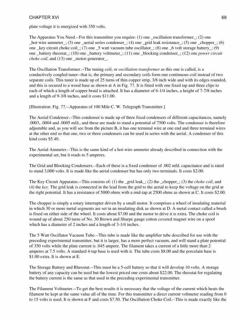
plate voltage it is energized with 350 volts.
The Apparatus You Need.--For this transmitter you require: (1) one _oscillation transformer_; (2) one_hot-wire ammeter_; (3) one _aerial series condenser_; (4) one _grid leak resistance_; (5) one _chopper_; (6)one _key circuit choke coil_; (7) one _5 watt vacuum tube oscillator_; (8) one _6 volt storage battery_; (9)one _battery rheostat_; (10) one _battery voltmeter_; (11) one _blocking condenser_; (12) one power circuitchoke coil, and (13) one _motor-generator_.
The Oscillation Transformer.--The tuning coil, or oscillation transformer as this one is called, is aconductively coupled tuner--that is, the primary and secondary coils form one continuous coil instead of twoseparate coils. This tuner is made up of 25 turns of thin copper strip, 3/8 inch wide and with its edges rounded,and this is secured to a wood base as shown at A in Fig. 77. It is fitted with one fixed tap and three clips toeach of which a length of copper braid is attached. It has a diameter of 6-1/4 inches, a height of 7-7/8 inchesand a length of 9-3/8 inches, and it costs $11.00.
[Illustration: Fig. 77.--Apparatus of 100 Mile C. W. Telegraph Transmitter.]
The Aerial Condenser.--This condenser is made up of three fixed condensers of different capacitances, namely.0003, .0004 and .0005 mfd., and these are made to stand a potential of 7500 volts. The condenser is thereforeadjustable and, as you will see from the picture B, it has one terminal wire at one end and three terminal wiresat the other end so that one, two or three condensers can be used in series with the aerial. A condenser of thiskind costs $5.40.
The Aerial Ammeter.--This is the same kind of a hot-wire ammeter already described in connection with theexperimental set, but it reads to 5 amperes.
The Grid and Blocking Condensers.--Each of these is a fixed condenser of .002 mfd. capacitance and is ratedto stand 3,000 volts. It is made like the aerial condenser but has only two terminals. It costs $2.00.
The Key Circuit Apparatus.--This consists of: (1) the _grid leak_; (2) the _chopper_; (3) the choke coil, and(4) the key. The grid leak is connected in the lead from the grid to the aerial to keep the voltage on the grid atthe right potential. It has a resistance of 5000 ohms with a mid-tap at 2500 ohms as shown at C. It costs $2.00.
The chopper is simply a rotary interrupter driven by a small motor. It comprises a wheel of insulating materialin which 30 or more metal segments are set in an insulating disk as shown at D. A metal contact called a brushis fixed on either side of the wheel. It costs about $7.00 and the motor to drive it is extra. The choke coil iswound up of about 250 turns of No. 30 Brown and Sharpe gauge cotton covered magnet wire on a spoolwhich has a diameter of 2 inches and a length of 3-1/4 inches.
The 5 Watt Oscillator Vacuum Tube.--This tube is made like the amplifier tube described for use with thepreceding experimental transmitter, but it is larger, has a more perfect vacuum, and will stand a plate potentialof 350 volts while the plate current is .045 ampere. The filament takes a current of a little more than 2amperes at 7.5 volts. A standard 4-tap base is used with it. The tube costs $8.00 and the porcelain base is$1.00 extra. It is shown at E.
The Storage Battery and Rheostat.--This must be a 5-cell battery so that it will develop 10 volts. A storagebattery of any capacity can be used but the lowest priced one costs about $22.00. The rheostat for regulatingthe battery current is the same as that used in the preceding experimental transmitter.
The Filament Voltmeter.--To get the best results it is necessary that the voltage of the current which heats thefilament be kept at the same value all of the time. For this transmitter a direct current voltmeter reading from 0to 15 volts is used. It is shown at F and costs $7.50. The Oscillation Choke Coil.--This is made exactly like the
CHAPTER XVI 69
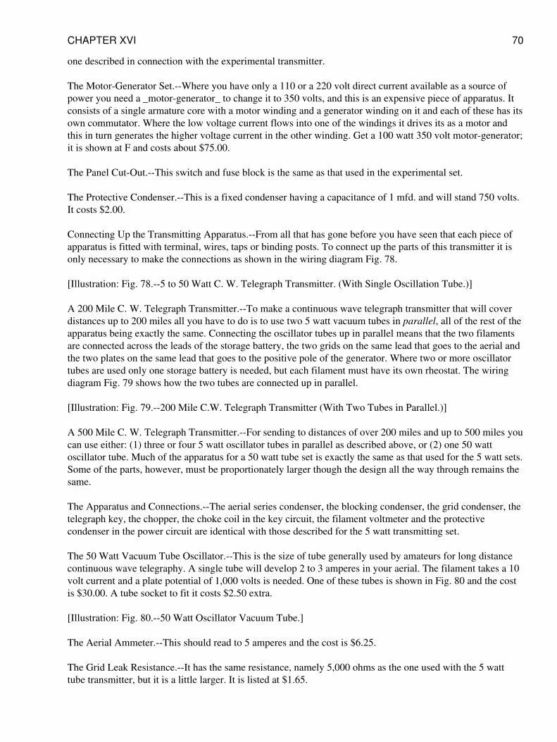
one described in connection with the experimental transmitter.
The Motor-Generator Set.--Where you have only a 110 or a 220 volt direct current available as a source ofpower you need a _motor-generator_ to change it to 350 volts, and this is an expensive piece of apparatus. Itconsists of a single armature core with a motor winding and a generator winding on it and each of these has itsown commutator. Where the low voltage current flows into one of the windings it drives its as a motor andthis in turn generates the higher voltage current in the other winding. Get a 100 watt 350 volt motor-generator;it is shown at F and costs about $75.00.
The Panel Cut-Out.--This switch and fuse block is the same as that used in the experimental set.
The Protective Condenser.--This is a fixed condenser having a capacitance of 1 mfd. and will stand 750 volts.It costs $2.00.
Connecting Up the Transmitting Apparatus.--From all that has gone before you have seen that each piece ofapparatus is fitted with terminal, wires, taps or binding posts. To connect up the parts of this transmitter it isonly necessary to make the connections as shown in the wiring diagram Fig. 78.
[Illustration: Fig. 78.--5 to 50 Watt C. W. Telegraph Transmitter. (With Single Oscillation Tube.)]
A 200 Mile C. W. Telegraph Transmitter.--To make a continuous wave telegraph transmitter that will coverdistances up to 200 miles all you have to do is to use two 5 watt vacuum tubes in parallel, all of the rest of theapparatus being exactly the same. Connecting the oscillator tubes up in parallel means that the two filamentsare connected across the leads of the storage battery, the two grids on the same lead that goes to the aerial andthe two plates on the same lead that goes to the positive pole of the generator. Where two or more oscillatortubes are used only one storage battery is needed, but each filament must have its own rheostat. The wiringdiagram Fig. 79 shows how the two tubes are connected up in parallel.
[Illustration: Fig. 79.--200 Mile C.W. Telegraph Transmitter (With Two Tubes in Parallel.)]
A 500 Mile C. W. Telegraph Transmitter.--For sending to distances of over 200 miles and up to 500 miles youcan use either: (1) three or four 5 watt oscillator tubes in parallel as described above, or (2) one 50 wattoscillator tube. Much of the apparatus for a 50 watt tube set is exactly the same as that used for the 5 watt sets.Some of the parts, however, must be proportionately larger though the design all the way through remains thesame.
The Apparatus and Connections.--The aerial series condenser, the blocking condenser, the grid condenser, thetelegraph key, the chopper, the choke coil in the key circuit, the filament voltmeter and the protectivecondenser in the power circuit are identical with those described for the 5 watt transmitting set.
The 50 Watt Vacuum Tube Oscillator.--This is the size of tube generally used by amateurs for long distancecontinuous wave telegraphy. A single tube will develop 2 to 3 amperes in your aerial. The filament takes a 10volt current and a plate potential of 1,000 volts is needed. One of these tubes is shown in Fig. 80 and the costis $30.00. A tube socket to fit it costs $2.50 extra.
[Illustration: Fig. 80.--50 Watt Oscillator Vacuum Tube.]
The Aerial Ammeter.--This should read to 5 amperes and the cost is $6.25.
The Grid Leak Resistance.--It has the same resistance, namely 5,000 ohms as the one used with the 5 watttube transmitter, but it is a little larger. It is listed at $1.65.
CHAPTER XVI 70
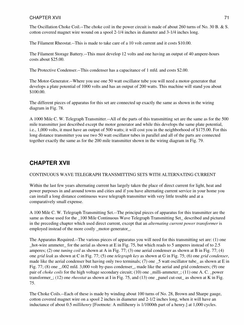
The Oscillation Choke Coil.--The choke coil in the power circuit is made of about 260 turns of No. 30 B. & S.cotton covered magnet wire wound on a spool 2-1/4 inches in diameter and 3-1/4 inches long.
The Filament Rheostat.--This is made to take care of a 10 volt current and it costs $10.00.
The Filament Storage Battery.--This must develop 12 volts and one having an output of 40 ampere-hourscosts about $25.00.
The Protective Condenser.--This condenser has a capacitance of 1 mfd. and costs $2.00.
The Motor-Generator.--Where you use one 50 watt oscillator tube you will need a motor-generator thatdevelops a plate potential of 1000 volts and has an output of 200 watts. This machine will stand you about$100.00.
The different pieces of apparatus for this set are connected up exactly the same as shown in the wiringdiagram in Fig. 78.
A 1000 Mile C. W. Telegraph Transmitter.--All of the parts of this transmitting set are the same as for the 500mile transmitter just described except the motor generator and while this develops the same plate potential,i.e., 1,000 volts, it must have an output of 500 watts; it will cost you in the neighborhood of $175.00. For thislong distance transmitter you use two 50 watt oscillator tubes in parallel and all of the parts are connectedtogether exactly the same as for the 200 mile transmitter shown in the wiring diagram in Fig. 79.
CHAPTER XVII
CONTINUOUS WAVE TELEGRAPH TRANSMITTING SETS WITH ALTERNATING CURRENT
Within the last few years alternating current has largely taken the place of direct current for light, heat andpower purposes in and around towns and cities and if you have alternating current service in your home youcan install a long distance continuous wave telegraph transmitter with very little trouble and at acomparatively small expense.
A 100 Mile C. W. Telegraph Transmitting Set.--The principal pieces of apparatus for this transmitter are thesame as those used for the _100 Mile Continuous Wave Telegraph Transmitting Set_ described and picturedin the preceding chapter which used direct current, except that an alternating current power transformer isemployed instead of the more costly _motor-generator_.
The Apparatus Required.--The various pieces of apparatus you will need for this transmitting set are: (1) one_hot-wire ammeter_ for the aerial as shown at E in Fig. 75, but which reads to 5 amperes instead of to 2.5amperes; (2) one tuning coil as shown at A in Fig. 77; (3) one aerial condenser as shown at B in Fig. 77; (4)one grid leak as shown at C in Fig. 77; (5) one telegraph key as shown at G in Fig. 75; (6) one grid condenser,made like the aerial condenser but having only two terminals; (7) one _5 watt oscillator tube_ as shown at E inFig. 77; (8) one _.002 mfd. 3,000 volt by-pass condenser_, made like the aerial and grid condensers; (9) onepair of choke coils for the high voltage secondary circuit; (10) one _milli-ammeter_; (11) one A. C. _powertransformer_; (12) one rheostat as shown at I in Fig. 75, and (13) one _panel cut-out_ as shown at K in Fig.75.
The Choke Coils.--Each of these is made by winding about 100 turns of No. 28, Brown and Sharpe gauge,cotton covered magnet wire on a spool 2 inches in diameter and 2-1/2 inches long, when it will have aninductance of about 0.5 millihenry [Footnote: A millihenry is 1/1000th part of a henry.] at 1,000 cycles.
CHAPTER XVII 71
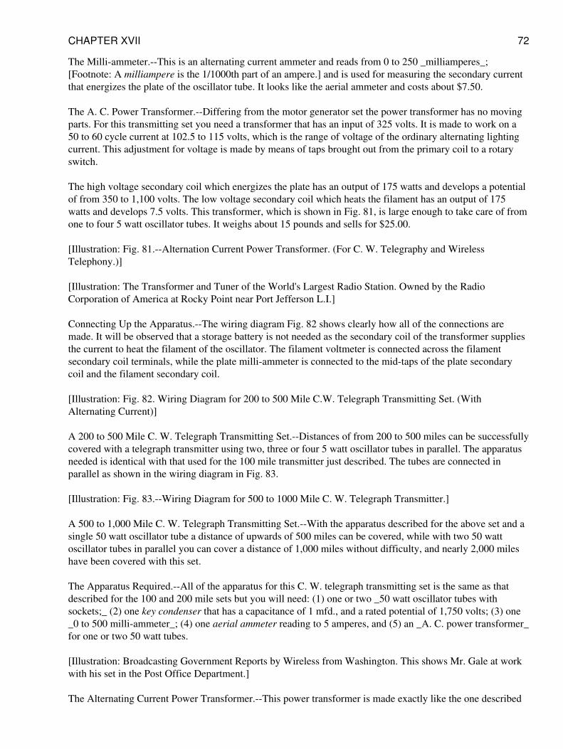
The Milli-ammeter.--This is an alternating current ammeter and reads from 0 to 250 _milliamperes_;[Footnote: A milliampere is the 1/1000th part of an ampere.] and is used for measuring the secondary currentthat energizes the plate of the oscillator tube. It looks like the aerial ammeter and costs about $7.50.
The A. C. Power Transformer.--Differing from the motor generator set the power transformer has no movingparts. For this transmitting set you need a transformer that has an input of 325 volts. It is made to work on a50 to 60 cycle current at 102.5 to 115 volts, which is the range of voltage of the ordinary alternating lightingcurrent. This adjustment for voltage is made by means of taps brought out from the primary coil to a rotaryswitch.
The high voltage secondary coil which energizes the plate has an output of 175 watts and develops a potentialof from 350 to 1,100 volts. The low voltage secondary coil which heats the filament has an output of 175watts and develops 7.5 volts. This transformer, which is shown in Fig. 81, is large enough to take care of fromone to four 5 watt oscillator tubes. It weighs about 15 pounds and sells for $25.00.
[Illustration: Fig. 81.--Alternation Current Power Transformer. (For C. W. Telegraphy and WirelessTelephony.)]
[Illustration: The Transformer and Tuner of the World's Largest Radio Station. Owned by the RadioCorporation of America at Rocky Point near Port Jefferson L.I.]
Connecting Up the Apparatus.--The wiring diagram Fig. 82 shows clearly how all of the connections aremade. It will be observed that a storage battery is not needed as the secondary coil of the transformer suppliesthe current to heat the filament of the oscillator. The filament voltmeter is connected across the filamentsecondary coil terminals, while the plate milli-ammeter is connected to the mid-taps of the plate secondarycoil and the filament secondary coil.
[Illustration: Fig. 82. Wiring Diagram for 200 to 500 Mile C.W. Telegraph Transmitting Set. (WithAlternating Current)]
A 200 to 500 Mile C. W. Telegraph Transmitting Set.--Distances of from 200 to 500 miles can be successfullycovered with a telegraph transmitter using two, three or four 5 watt oscillator tubes in parallel. The apparatusneeded is identical with that used for the 100 mile transmitter just described. The tubes are connected inparallel as shown in the wiring diagram in Fig. 83.
[Illustration: Fig. 83.--Wiring Diagram for 500 to 1000 Mile C. W. Telegraph Transmitter.]
A 500 to 1,000 Mile C. W. Telegraph Transmitting Set.--With the apparatus described for the above set and asingle 50 watt oscillator tube a distance of upwards of 500 miles can be covered, while with two 50 wattoscillator tubes in parallel you can cover a distance of 1,000 miles without difficulty, and nearly 2,000 mileshave been covered with this set.
The Apparatus Required.--All of the apparatus for this C. W. telegraph transmitting set is the same as thatdescribed for the 100 and 200 mile sets but you will need: (1) one or two _50 watt oscillator tubes withsockets;_ (2) one key condenser that has a capacitance of 1 mfd., and a rated potential of 1,750 volts; (3) one_0 to 500 milli-ammeter_; (4) one aerial ammeter reading to 5 amperes, and (5) an _A. C. power transformer_for one or two 50 watt tubes.
[Illustration: Broadcasting Government Reports by Wireless from Washington. This shows Mr. Gale at workwith his set in the Post Office Department.]
The Alternating Current Power Transformer.--This power transformer is made exactly like the one described
CHAPTER XVII 72
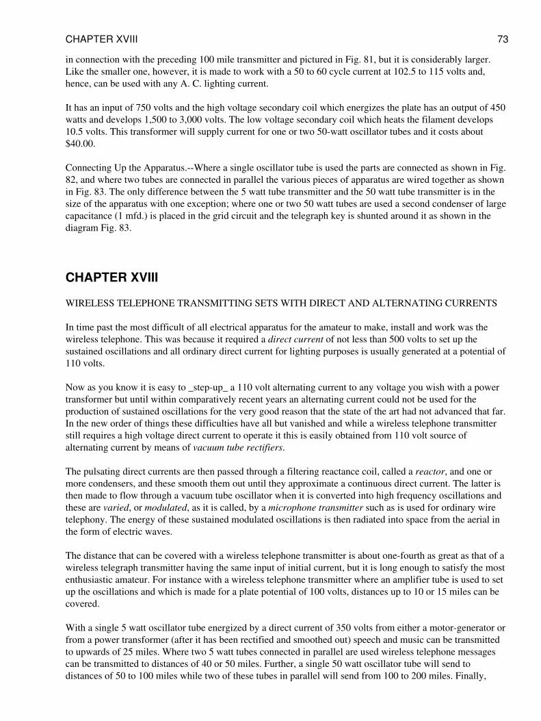
in connection with the preceding 100 mile transmitter and pictured in Fig. 81, but it is considerably larger.Like the smaller one, however, it is made to work with a 50 to 60 cycle current at 102.5 to 115 volts and,hence, can be used with any A. C. lighting current.
It has an input of 750 volts and the high voltage secondary coil which energizes the plate has an output of 450watts and develops 1,500 to 3,000 volts. The low voltage secondary coil which heats the filament develops10.5 volts. This transformer will supply current for one or two 50-watt oscillator tubes and it costs about$40.00.
Connecting Up the Apparatus.--Where a single oscillator tube is used the parts are connected as shown in Fig.82, and where two tubes are connected in parallel the various pieces of apparatus are wired together as shownin Fig. 83. The only difference between the 5 watt tube transmitter and the 50 watt tube transmitter is in thesize of the apparatus with one exception; where one or two 50 watt tubes are used a second condenser of largecapacitance (1 mfd.) is placed in the grid circuit and the telegraph key is shunted around it as shown in thediagram Fig. 83.
CHAPTER XVIII
WIRELESS TELEPHONE TRANSMITTING SETS WITH DIRECT AND ALTERNATING CURRENTS
In time past the most difficult of all electrical apparatus for the amateur to make, install and work was thewireless telephone. This was because it required a direct current of not less than 500 volts to set up thesustained oscillations and all ordinary direct current for lighting purposes is usually generated at a potential of110 volts.
Now as you know it is easy to _step-up_ a 110 volt alternating current to any voltage you wish with a powertransformer but until within comparatively recent years an alternating current could not be used for theproduction of sustained oscillations for the very good reason that the state of the art had not advanced that far.In the new order of things these difficulties have all but vanished and while a wireless telephone transmitterstill requires a high voltage direct current to operate it this is easily obtained from 110 volt source ofalternating current by means of vacuum tube rectifiers.
The pulsating direct currents are then passed through a filtering reactance coil, called a reactor, and one ormore condensers, and these smooth them out until they approximate a continuous direct current. The latter isthen made to flow through a vacuum tube oscillator when it is converted into high frequency oscillations andthese are varied, or modulated, as it is called, by a microphone transmitter such as is used for ordinary wiretelephony. The energy of these sustained modulated oscillations is then radiated into space from the aerial inthe form of electric waves.
The distance that can be covered with a wireless telephone transmitter is about one-fourth as great as that of awireless telegraph transmitter having the same input of initial current, but it is long enough to satisfy the mostenthusiastic amateur. For instance with a wireless telephone transmitter where an amplifier tube is used to setup the oscillations and which is made for a plate potential of 100 volts, distances up to 10 or 15 miles can becovered.
With a single 5 watt oscillator tube energized by a direct current of 350 volts from either a motor-generator orfrom a power transformer (after it has been rectified and smoothed out) speech and music can be transmittedto upwards of 25 miles. Where two 5 watt tubes connected in parallel are used wireless telephone messagescan be transmitted to distances of 40 or 50 miles. Further, a single 50 watt oscillator tube will send todistances of 50 to 100 miles while two of these tubes in parallel will send from 100 to 200 miles. Finally,
CHAPTER XVIII 73
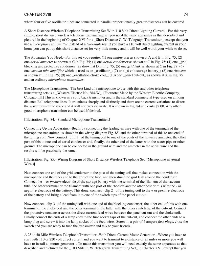
where four or five oscillator tubes are connected in parallel proportionately greater distances can be covered.
A Short Distance Wireless Telephone Transmitting Set-With 110 Volt Direct Lighting Current.--For this verysimple, short distance wireless telephone transmitting set you need the same apparatus as that described andpictured in the beginning of Chapter XVI for a _Short Distance C. W. Telegraph Transmitter_, except that youuse a microphone transmitter instead of a telegraph key. If you have a 110 volt direct lighting current in yourhome you can put up this short distance set for very little money and it will be well worth your while to do so.
The Apparatus You Need.--For this set you require: (1) one tuning coil as shown at A and B in Fig. 75; (2)one aerial ammeter as shown at C in Fig. 75; (3) one aerial condenser as shown at C in Fig. 75; (4) one _grid,blocking and protective condenser_ as shown at D in Fig. 75; (5) one grid leak as shown at C in Fig. 77; (6)one vacuum tube amplifier which is used as an _oscillator_; (7) one _6 volt storage battery_; (8) one rheostatas shown at I in Fig. 75; (9) one _oscillation choke coil_; (10) one _panel cut-out_ as shown at K in Fig. 75and an ordinary microphone transmitter.
The Microphone Transmitter.--The best kind of a microphone to use with this and other telephonetransmitting sets is a _Western Electric No. 284-W_. [Footnote: Made by the Western Electric Company,Chicago, Ill.] This is known as a solid back transmitter and is the standard commercial type used on all longdistance Bell telephone lines. It articulates sharply and distinctly and there are no current variations to distortthe wave form of the voice and it will not buzz or sizzle. It is shown in Fig. 84 and costs $2.00. Any othergood microphone transmitter can be used if desired.
[Illustration: Fig. 84.--Standard Microphone Transmitter.]
Connecting Up the Apparatus.--Begin by connecting the leading-in wire with one of the terminals of themicrophone transmitter, as shown in the wiring diagram Fig. 85, and the other terminal of this to one end ofthe tuning coil. Now connect _clip 1_ of the tuning coil to one of the posts of the hot-wire ammeter, the otherpost of this to one end of aerial condenser and, finally, the other end of the latter with the water pipe or otherground. The microphone can be connected in the ground wire and the ammeter in the aerial wire and theresults will be practically the same.
[Illustration: Fig. 85.--Wiring Diagram of Short Distance Wireless Telephone Set. (Microphone in AerialWire.)]
Next connect one end of the grid condenser to the post of the tuning coil that makes connection with themicrophone and the other end to the grid of the tube, and then shunt the grid leak around the condenser.Connect the + or positive electrode of the storage battery with one terminal of the filament of the vacuumtube, the other terminal of the filament with one post of the rheostat and the other post of this with the - ornegative electrode of the battery. This done, connect _clip 2_ of the tuning coil to the + or positive electrodeof the battery and bring a lead from it to one of the switch taps of the panel cut-out.
Now connect _clip 3_ of the tuning coil with one end of the blocking condenser, the other end of this with oneterminal of the choke coil and the other terminal of the latter with the other switch tap of the cut-out. Connectthe protective condenser across the direct current feed wires between the panel cut-out and the choke coil.Finally connect the ends of a lamp cord to the fuse socket taps of the cut-out, and connect the other ends to alamp plug and screw it into the lamp socket of the feed wires. Screw in a pair of 5 ampere fuse plugs, close theswitch and you are ready to tune the transmitter and talk to your friends.
A 25 to 50 Mile Wireless Telephone Transmitter--With Direct Current Motor Generator.--Where you have tostart with 110 or 220 volt direct current and you want to transmit to a distance of 25 miles or more you willhave to install a _motor-generator_. To make this transmitter you will need exactly the same apparatus as thatdescribed and pictured for the _100 Mile C. W. Telegraph Transmitting Set_ in Chapter XVI, except that you
CHAPTER XVIII 74
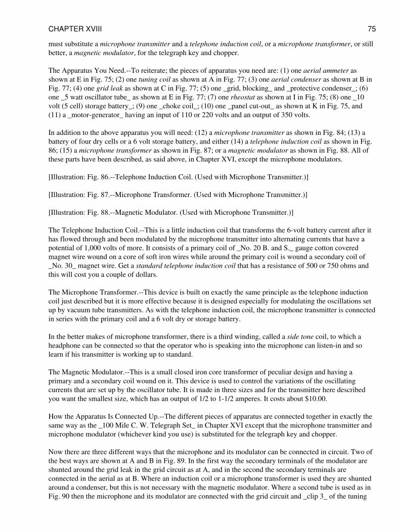
must substitute a microphone transmitter and a telephone induction coil, or a microphone transformer, or stillbetter, a magnetic modulator, for the telegraph key and chopper.
The Apparatus You Need.--To reiterate; the pieces of apparatus you need are: (1) one aerial ammeter asshown at E in Fig. 75; (2) one tuning coil as shown at A in Fig. 77; (3) one aerial condenser as shown at B inFig. 77; (4) one grid leak as shown at C in Fig. 77; (5) one _grid, blocking_ and _protective condenser_; (6)one _5 watt oscillator tube_ as shown at E in Fig. 77; (7) one rheostat as shown at I in Fig. 75; (8) one _10volt (5 cell) storage battery_; (9) one _choke coil_; (10) one _panel cut-out_ as shown at K in Fig. 75, and(11) a _motor-generator_ having an input of 110 or 220 volts and an output of 350 volts.
In addition to the above apparatus you will need: (12) a microphone transmitter as shown in Fig. 84; (13) abattery of four dry cells or a 6 volt storage battery, and either (14) a telephone induction coil as shown in Fig.86; (15) a microphone transformer as shown in Fig. 87; or a magnetic modulator as shown in Fig. 88. All ofthese parts have been described, as said above, in Chapter XVI, except the microphone modulators.
[Illustration: Fig. 86.--Telephone Induction Coil. (Used with Microphone Transmitter.)]
[Illustration: Fig. 87.--Microphone Transformer. (Used with Microphone Transmitter.)]
[Illustration: Fig. 88.--Magnetic Modulator. (Used with Microphone Transmitter.)]
The Telephone Induction Coil.--This is a little induction coil that transforms the 6-volt battery current after ithas flowed through and been modulated by the microphone transmitter into alternating currents that have apotential of 1,000 volts of more. It consists of a primary coil of _No. 20 B. and S._ gauge cotton coveredmagnet wire wound on a core of soft iron wires while around the primary coil is wound a secondary coil of_No. 30_ magnet wire. Get a standard telephone induction coil that has a resistance of 500 or 750 ohms andthis will cost you a couple of dollars.
The Microphone Transformer.--This device is built on exactly the same principle as the telephone inductioncoil just described but it is more effective because it is designed especially for modulating the oscillations setup by vacuum tube transmitters. As with the telephone induction coil, the microphone transmitter is connectedin series with the primary coil and a 6 volt dry or storage battery.
In the better makes of microphone transformer, there is a third winding, called a side tone coil, to which aheadphone can be connected so that the operator who is speaking into the microphone can listen-in and solearn if his transmitter is working up to standard.
The Magnetic Modulator.--This is a small closed iron core transformer of peculiar design and having aprimary and a secondary coil wound on it. This device is used to control the variations of the oscillatingcurrents that are set up by the oscillator tube. It is made in three sizes and for the transmitter here describedyou want the smallest size, which has an output of 1/2 to 1-1/2 amperes. It costs about $10.00.
How the Apparatus Is Connected Up.--The different pieces of apparatus are connected together in exactly thesame way as the _100 Mile C. W. Telegraph Set_ in Chapter XVI except that the microphone transmitter andmicrophone modulator (whichever kind you use) is substituted for the telegraph key and chopper.
Now there are three different ways that the microphone and its modulator can be connected in circuit. Two ofthe best ways are shown at A and B in Fig. 89. In the first way the secondary terminals of the modulator areshunted around the grid leak in the grid circuit as at A, and in the second the secondary terminals areconnected in the aerial as at B. Where an induction coil or a microphone transformer is used they are shuntedaround a condenser, but this is not necessary with the magnetic modulator. Where a second tube is used as inFig. 90 then the microphone and its modulator are connected with the grid circuit and _clip 3_ of the tuning
CHAPTER XVIII 75
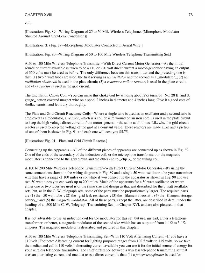
coil.
[Illustration: Fig. 89.--Wiring Diagram of 25 to 50 Mile Wireless Telephone. (Microphone ModulatorShunted Around Grid-Leak Condenser.)]
[Illustration: (B) Fig. 89.--Microphone Modulator Connected in Aerial Wire.]
[Illustration: Fig. 90.--Wiring Diagram of 50 to 100 Mile Wireless Telephone Transmitting Set.]
A 50 to 100 Mile Wireless Telephone Transmitter--With Direct Current Motor Generator.--As the initialsource of current available is taken to be a 110 or 220 volt direct current a motor-generator having an outputof 350 volts must be used as before. The only difference between this transmitter and the preceding one isthat: (1) two 5 watt tubes are used, the first serving as an oscillator and the second as a _modulator_; (2) anoscillation choke coil is used in the plate circuit; (3) a reactance coil or reactor, is used in the plate circuit;and (4) a reactor is used in the grid circuit.
The Oscillation Choke Coil.--You can make this choke coil by winding about 275 turns of _No. 28 B. and S.gauge_ cotton covered magnet wire on a spool 2 inches in diameter and 4 inches long. Give it a good coat ofshellac varnish and let it dry thoroughly.
The Plate and Grid Circuit Reactance Coils.--Where a single tube is used as an oscillator and a second tube isemployed as a modulator, a reactor, which is a coil of wire wound on an iron core, is used in the plate circuitto keep the high voltage direct current of the motor-generator the same at all times. Likewise the grid circuitreactor is used to keep the voltage of the grid at a constant value. These reactors are made alike and a pictureof one of them is shown in Fig. 91 and each one will cost you $5.75.
[Illustration: Fig. 91.--Plate and Grid Circuit Reactor.]
Connecting up the Apparatus.--All of the different pieces of apparatus are connected up as shown in Fig. 89.One of the ends of the secondary of the induction coil, or the microphone transformer, or the magneticmodulator is connected to the grid circuit and the other end to _clip 3_ of the tuning coil.
A 100 to 200 Mile Wireless Telephone Transmitter--With Direct Current Motor Generator.--By using thesame connections shown in the wiring diagrams in Fig. 89 and a single 50 watt oscillator tube your transmitterwill then have a range of 100 miles or so, while if you connect up the apparatus as shown in Fig. 90 and usetwo 50 watt tubes you can work up to 200 miles. Much of the apparatus for a 50 watt oscillator set whereeither one or two tubes are used is of the same size and design as that just described for the 5 watt oscillatorsets, but, as in the C. W. telegraph sets, some of the parts must be proportionately larger. The required partsare (1) the _50 watt tube_; (2) the _grid leak resistance_; (3) the _filament rheostat_; (4) the _filament storagebattery_; and (5) the magnetic modulator. All of these parts, except the latter, are described in detail under theheading of a _500 Mile C. W. Telegraph Transmitting Set_ in Chapter XVI, and are also pictured in thatchapter.
It is not advisable to use an induction coil for the modulator for this set, but use, instead, either a telephonetransformer, or better, a magnetic modulator of the second size which has an output of from 1-1/2 to 3-1/2amperes. The magnetic modulator is described and pictured in this chapter.
A 50 to 100 Mile Wireless Telephone Transmitting Set--With 110 Volt Alternating Current.--If you have a110 volt [Footnote: Alternating current for lighting purposes ranges from 102.5 volts to 115 volts, so we takethe median and call it 110 volts.] alternating current available you can use it for the initial source of energy foryour wireless telephone transmitter. The chief difference between a wireless telephone transmitting set thatuses an alternating current and one that uses a direct current is that: (1) a power transformer is used for
CHAPTER XVIII 76
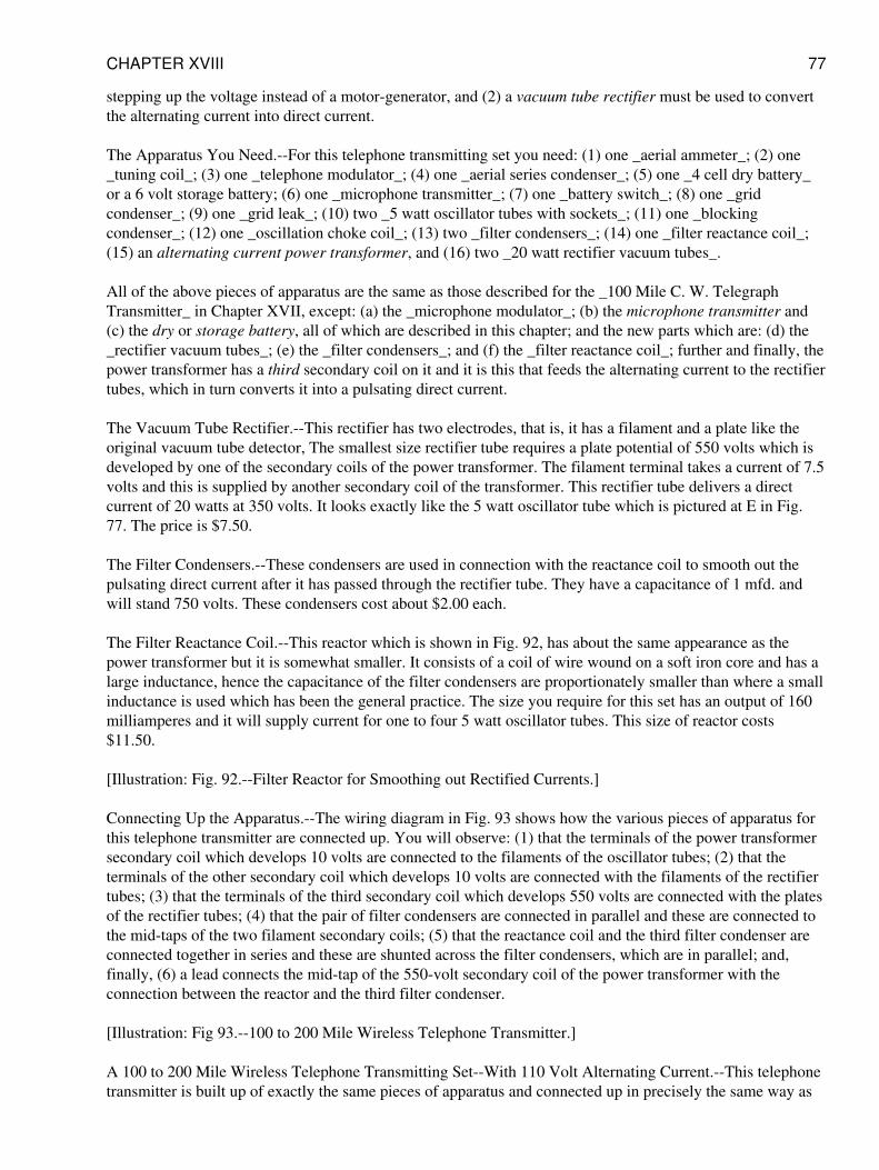
stepping up the voltage instead of a motor-generator, and (2) a vacuum tube rectifier must be used to convertthe alternating current into direct current.
The Apparatus You Need.--For this telephone transmitting set you need: (1) one _aerial ammeter_; (2) one_tuning coil_; (3) one _telephone modulator_; (4) one _aerial series condenser_; (5) one _4 cell dry battery_or a 6 volt storage battery; (6) one _microphone transmitter_; (7) one _battery switch_; (8) one _gridcondenser_; (9) one _grid leak_; (10) two _5 watt oscillator tubes with sockets_; (11) one _blockingcondenser_; (12) one _oscillation choke coil_; (13) two _filter condensers_; (14) one _filter reactance coil_;(15) an alternating current power transformer, and (16) two _20 watt rectifier vacuum tubes_.
All of the above pieces of apparatus are the same as those described for the _100 Mile C. W. TelegraphTransmitter_ in Chapter XVII, except: (a) the _microphone modulator_; (b) the microphone transmitter and(c) the dry or storage battery, all of which are described in this chapter; and the new parts which are: (d) the_rectifier vacuum tubes_; (e) the _filter condensers_; and (f) the _filter reactance coil_; further and finally, thepower transformer has a third secondary coil on it and it is this that feeds the alternating current to the rectifiertubes, which in turn converts it into a pulsating direct current.
The Vacuum Tube Rectifier.--This rectifier has two electrodes, that is, it has a filament and a plate like theoriginal vacuum tube detector, The smallest size rectifier tube requires a plate potential of 550 volts which isdeveloped by one of the secondary coils of the power transformer. The filament terminal takes a current of 7.5volts and this is supplied by another secondary coil of the transformer. This rectifier tube delivers a directcurrent of 20 watts at 350 volts. It looks exactly like the 5 watt oscillator tube which is pictured at E in Fig.77. The price is $7.50.
The Filter Condensers.--These condensers are used in connection with the reactance coil to smooth out thepulsating direct current after it has passed through the rectifier tube. They have a capacitance of 1 mfd. andwill stand 750 volts. These condensers cost about $2.00 each.
The Filter Reactance Coil.--This reactor which is shown in Fig. 92, has about the same appearance as thepower transformer but it is somewhat smaller. It consists of a coil of wire wound on a soft iron core and has alarge inductance, hence the capacitance of the filter condensers are proportionately smaller than where a smallinductance is used which has been the general practice. The size you require for this set has an output of 160milliamperes and it will supply current for one to four 5 watt oscillator tubes. This size of reactor costs$11.50.
[Illustration: Fig. 92.--Filter Reactor for Smoothing out Rectified Currents.]
Connecting Up the Apparatus.--The wiring diagram in Fig. 93 shows how the various pieces of apparatus forthis telephone transmitter are connected up. You will observe: (1) that the terminals of the power transformersecondary coil which develops 10 volts are connected to the filaments of the oscillator tubes; (2) that theterminals of the other secondary coil which develops 10 volts are connected with the filaments of the rectifiertubes; (3) that the terminals of the third secondary coil which develops 550 volts are connected with the platesof the rectifier tubes; (4) that the pair of filter condensers are connected in parallel and these are connected tothe mid-taps of the two filament secondary coils; (5) that the reactance coil and the third filter condenser areconnected together in series and these are shunted across the filter condensers, which are in parallel; and,finally, (6) a lead connects the mid-tap of the 550-volt secondary coil of the power transformer with theconnection between the reactor and the third filter condenser.
[Illustration: Fig 93.--100 to 200 Mile Wireless Telephone Transmitter.]
A 100 to 200 Mile Wireless Telephone Transmitting Set--With 110 Volt Alternating Current.--This telephonetransmitter is built up of exactly the same pieces of apparatus and connected up in precisely the same way as
CHAPTER XVIII 77
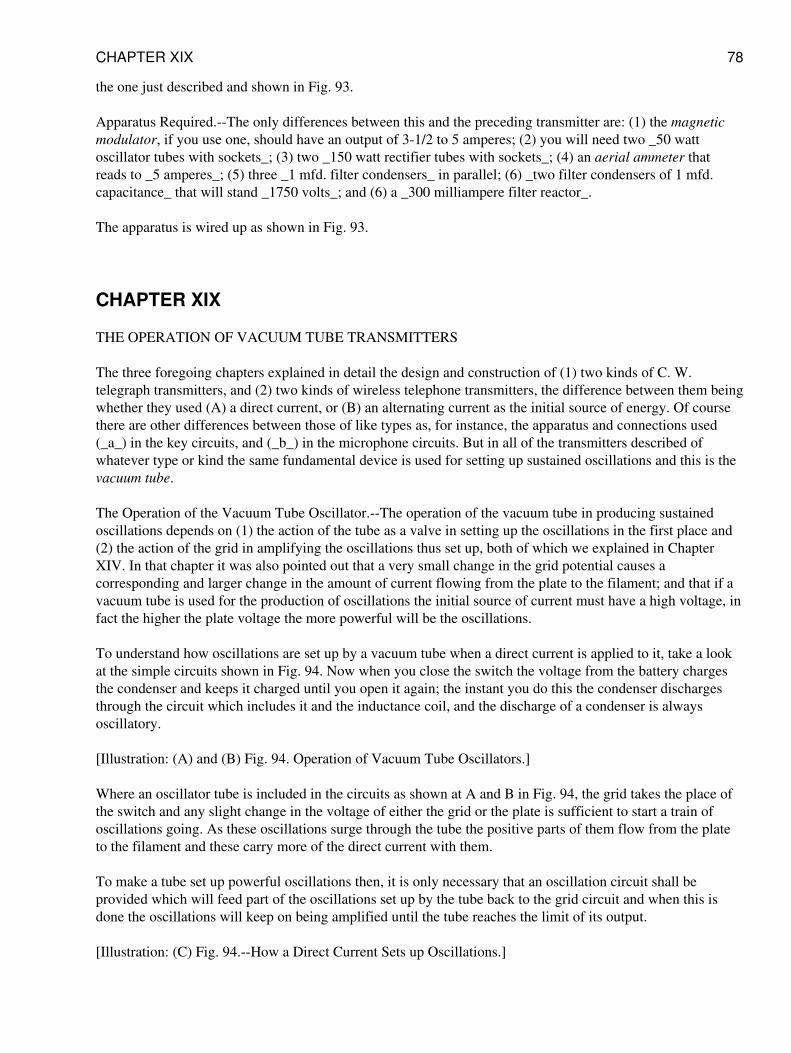
the one just described and shown in Fig. 93.
Apparatus Required.--The only differences between this and the preceding transmitter are: (1) the magneticmodulator, if you use one, should have an output of 3-1/2 to 5 amperes; (2) you will need two _50 wattoscillator tubes with sockets_; (3) two _150 watt rectifier tubes with sockets_; (4) an aerial ammeter thatreads to _5 amperes_; (5) three _1 mfd. filter condensers_ in parallel; (6) _two filter condensers of 1 mfd.capacitance_ that will stand _1750 volts_; and (6) a _300 milliampere filter reactor_.
The apparatus is wired up as shown in Fig. 93.
CHAPTER XIX
THE OPERATION OF VACUUM TUBE TRANSMITTERS
The three foregoing chapters explained in detail the design and construction of (1) two kinds of C. W.telegraph transmitters, and (2) two kinds of wireless telephone transmitters, the difference between them beingwhether they used (A) a direct current, or (B) an alternating current as the initial source of energy. Of coursethere are other differences between those of like types as, for instance, the apparatus and connections used(_a_) in the key circuits, and (_b_) in the microphone circuits. But in all of the transmitters described ofwhatever type or kind the same fundamental device is used for setting up sustained oscillations and this is thevacuum tube.
The Operation of the Vacuum Tube Oscillator.--The operation of the vacuum tube in producing sustainedoscillations depends on (1) the action of the tube as a valve in setting up the oscillations in the first place and(2) the action of the grid in amplifying the oscillations thus set up, both of which we explained in ChapterXIV. In that chapter it was also pointed out that a very small change in the grid potential causes acorresponding and larger change in the amount of current flowing from the plate to the filament; and that if avacuum tube is used for the production of oscillations the initial source of current must have a high voltage, infact the higher the plate voltage the more powerful will be the oscillations.
To understand how oscillations are set up by a vacuum tube when a direct current is applied to it, take a lookat the simple circuits shown in Fig. 94. Now when you close the switch the voltage from the battery chargesthe condenser and keeps it charged until you open it again; the instant you do this the condenser dischargesthrough the circuit which includes it and the inductance coil, and the discharge of a condenser is alwaysoscillatory.
[Illustration: (A) and (B) Fig. 94. Operation of Vacuum Tube Oscillators.]
Where an oscillator tube is included in the circuits as shown at A and B in Fig. 94, the grid takes the place ofthe switch and any slight change in the voltage of either the grid or the plate is sufficient to start a train ofoscillations going. As these oscillations surge through the tube the positive parts of them flow from the plateto the filament and these carry more of the direct current with them.
To make a tube set up powerful oscillations then, it is only necessary that an oscillation circuit shall beprovided which will feed part of the oscillations set up by the tube back to the grid circuit and when this isdone the oscillations will keep on being amplified until the tube reaches the limit of its output.
[Illustration: (C) Fig. 94.--How a Direct Current Sets up Oscillations.]
CHAPTER XIX 78
The Operation of C. W. Telegraph Transmitters With Direct Current--Short Distance C. W. Transmitter.--Inthe transmitter shown in the wiring diagram in Fig. 76 the positive part of the 110 volt direct current is carrieddown from the lamp socket through one side of the panel cut-out, thence through the choke coil and to theplate of the oscillator tube, when the latter is charged to the positive sign. The negative part of the 110 voltdirect current then flows down the other wire to the filament so that there is a difference of potential betweenthe plate and the filament of 110 volts. Now when the 6-volt battery current is switched on the filament isheated to brilliancy, and the electrons thrown off by it form a conducting path between it and the plate; the110 volt current then flows from the latter to the former.
Now follow the wiring from the plate over to the blocking condenser, thence to _clip 3_ of the tuning coil,through the turns of the latter to _clip 2_ and over to the filament and, when the latter is heated, you have aclosed oscillation circuit. The oscillations surging in the latter set up other and like oscillations in the tuningcoil between the end of which is connected with the grid, the aerial and the _clip 2_, and these surge throughthe circuit formed by this portion of the coil, the grid condenser and the filament; this is the amplifying circuitand it corresponds to the regenerative circuit of a receiving set.
When oscillations are set up in it the grid is alternately charged to the positive and negative signs. Thesereversals of voltage set up stronger and ever stronger oscillations in the plate circuit as before explained. Notonly do the oscillations surge in the closed circuits but they run to and fro on the aerial wire when their energyis radiated in the form of electric waves. The oscillations are varied by means of the telegraph key which isplaced in the grid circuit as shown in Fig. 76.
The Operation of the Key Circuit.--The effect in a C. W. transmitter when a telegraph key is connected inseries with a buzzer and a battery and these are shunted around the condenser in the grid circuit, is to rapidlychange the wave form of the sustained oscillations, and hence, the length of the waves that are sent out. Whileno sound can be heard in the headphones at the receiving station so long as the points of the key are not incontact, when they are in contact the oscillations are modulated and sounds are heard in the headphones thatcorrespond to the frequency of the buzzer in the key circuit.
The Operation of C. W. Telegraph Transmitters with Direct Current.--The chief differences between the longdistance sets which use a direct current, i.e., those described in Chapter XVI, and the short distancetransmitting sets are that the former use: (1) a motor-generator set for changing the low voltage direct currentinto high voltage direct current, and (2) a chopper in the key circuit. The way the motor-generator changes thelow- into high-voltage current has been explained in Chapter XVI.
The chopper interrupts the oscillations surging through the grid circuit at a frequency that the ear can hear,that is to say, about 800 to 1,000 times per second. When the key is open, of course, the sustained oscillationsset up in the circuits will send out continuous waves but when the key is closed these oscillations are brokenup and then they send out discontinuous waves. If a heterodyne receiving set, see Chapter XV, is being used atthe other end you can dispense with the chopper and the key circuit needed is very much simplified. Theoperation of key circuits of the latter kind will be described presently.
The Operation of C. W. Telegraph Transmitters with Alternating Current--With a Single OscillatorTube.--Where an oscillator tube telegraph transmitter is operated by a 110 volt alternating current as the initialsource of energy, a buzzer, chopper or other interruptor is not needed in the key circuit. This is becauseoscillations are set up only when the plate is energized with the positive part of the alternating current and thisproduces an intermittent musical tone in the headphones. Hence this kind of a sending set is called a tonetransmitter.
Since oscillations are set up only by the positive part or voltage of an alternating current it is clear that, as amatter of fact, this kind of a transmitter does not send out continuous waves and therefore it is not a C. W.transmitter. This is graphically shown by the curve of the wave form of the alternating current and the
CHAPTER XIX 79
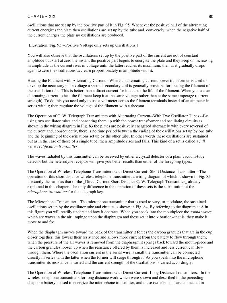
oscillations that are set up by the positive part of it in Fig. 95. Whenever the positive half of the alternatingcurrent energizes the plate then oscillations are set up by the tube and, conversely, when the negative half ofthe current charges the plate no oscillations are produced.
[Illustration: Fig. 95.--Positive Voltage only sets up Oscillations.]
You will also observe that the oscillations set up by the positive part of the current are not of constantamplitude but start at zero the instant the positive part begins to energize the plate and they keep on increasingin amplitude as the current rises in voltage until the latter reaches its maximum; then as it gradually dropsagain to zero the oscillations decrease proportionately in amplitude with it.
Heating the Filament with Alternating Current.--Where an alternating current power transformer is used todevelop the necessary plate voltage a second secondary coil is generally provided for heating the filament ofthe oscillation tube. This is better than a direct current for it adds to the life of the filament. When you use analternating current to heat the filament keep it at the same voltage rather than at the same amperage (currentstrength). To do this you need only to use a voltmeter across the filament terminals instead of an ammeter inseries with it; then regulate the voltage of the filament with a rheostat.
The Operation of C. W. Telegraph Transmitters with Alternating Current--With Two Oscillator Tubes.--Byusing two oscillator tubes and connecting them up with the power transformer and oscillating circuits asshown in the wiring diagram in Fig. 83 the plates are positively energized alternately with every reversal ofthe current and, consequently, there is no time period between the ending of the oscillations set up by one tubeand the beginning of the oscillations set up by the other tube. In other words these oscillations are sustainedbut as in the case of those of a single tube, their amplitude rises and falls. This kind of a set is called a fullwave rectification transmitter.
The waves radiated by this transmitter can be received by either a crystal detector or a plain vacuum-tubedetector but the heterodyne receptor will give you better results than either of the foregoing types.
The Operation of Wireless Telephone Transmitters with Direct Current--Short Distance Transmitter.--Theoperation of this short distance wireless telephone transmitter, a wiring diagram of which is shown in Fig. 85is exactly the same as that of the _Direct Current Short Distance C. W. Telegraph Transmitter_ alreadyexplained in this chapter. The only difference in the operation of these sets is the substitution of themicrophone transmitter for the telegraph key.
The Microphone Transmitter.--The microphone transmitter that is used to vary, or modulate, the sustainedoscillations set up by the oscillator tube and circuits is shown in Fig. 84. By referring to the diagram at A inthis figure you will readily understand how it operates. When you speak into the mouthpiece the sound waves,which are waves in the air, impinge upon the diaphragm and these set it into vibration--that is, they make itmove to and fro.
When the diaphragm moves toward the back of the transmitter it forces the carbon granules that are in the cupcloser together; this lowers their resistance and allows more current from the battery to flow through them;when the pressure of the air waves is removed from the diaphragm it springs back toward the mouth-piece andthe carbon granules loosen up when the resistance offered by them is increased and less current can flowthrough them. Where the oscillation current in the aerial wire is small the transmitter can be connecteddirectly in series with the latter when the former will surge through it. As you speak into the microphonetransmitter its resistance is varied and the current strength of the oscillations is varied accordingly.
The Operation of Wireless Telephone Transmitters with Direct Current--Long Distance Transmitters.--In thewireless telephone transmitters for long distance work which were shown and described in the precedingchapter a battery is used to energize the microphone transmitter, and these two elements are connected in
CHAPTER XIX 80
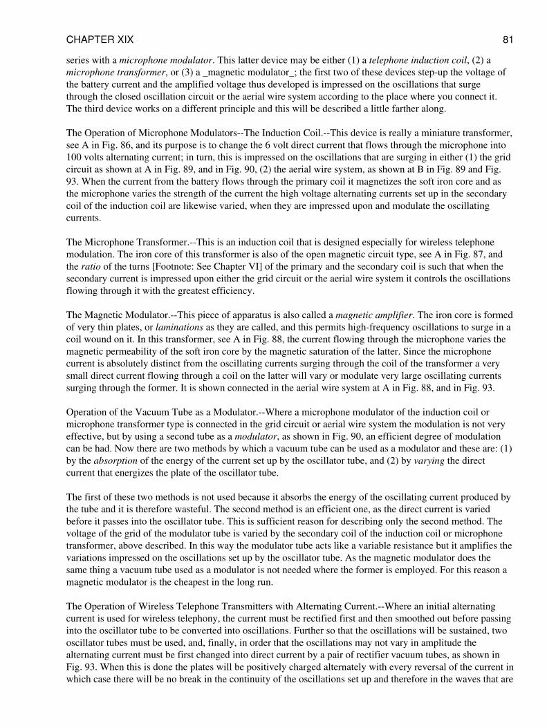
series with a microphone modulator. This latter device may be either (1) a telephone induction coil, (2) amicrophone transformer, or (3) a _magnetic modulator_; the first two of these devices step-up the voltage ofthe battery current and the amplified voltage thus developed is impressed on the oscillations that surgethrough the closed oscillation circuit or the aerial wire system according to the place where you connect it.The third device works on a different principle and this will be described a little farther along.
The Operation of Microphone Modulators--The Induction Coil.--This device is really a miniature transformer,see A in Fig. 86, and its purpose is to change the 6 volt direct current that flows through the microphone into100 volts alternating current; in turn, this is impressed on the oscillations that are surging in either (1) the gridcircuit as shown at A in Fig. 89, and in Fig. 90, (2) the aerial wire system, as shown at B in Fig. 89 and Fig.93. When the current from the battery flows through the primary coil it magnetizes the soft iron core and asthe microphone varies the strength of the current the high voltage alternating currents set up in the secondarycoil of the induction coil are likewise varied, when they are impressed upon and modulate the oscillatingcurrents.
The Microphone Transformer.--This is an induction coil that is designed especially for wireless telephonemodulation. The iron core of this transformer is also of the open magnetic circuit type, see A in Fig. 87, andthe ratio of the turns [Footnote: See Chapter VI] of the primary and the secondary coil is such that when thesecondary current is impressed upon either the grid circuit or the aerial wire system it controls the oscillationsflowing through it with the greatest efficiency.
The Magnetic Modulator.--This piece of apparatus is also called a magnetic amplifier. The iron core is formedof very thin plates, or laminations as they are called, and this permits high-frequency oscillations to surge in acoil wound on it. In this transformer, see A in Fig. 88, the current flowing through the microphone varies themagnetic permeability of the soft iron core by the magnetic saturation of the latter. Since the microphonecurrent is absolutely distinct from the oscillating currents surging through the coil of the transformer a verysmall direct current flowing through a coil on the latter will vary or modulate very large oscillating currentssurging through the former. It is shown connected in the aerial wire system at A in Fig. 88, and in Fig. 93.
Operation of the Vacuum Tube as a Modulator.--Where a microphone modulator of the induction coil ormicrophone transformer type is connected in the grid circuit or aerial wire system the modulation is not veryeffective, but by using a second tube as a modulator, as shown in Fig. 90, an efficient degree of modulationcan be had. Now there are two methods by which a vacuum tube can be used as a modulator and these are: (1)by the absorption of the energy of the current set up by the oscillator tube, and (2) by varying the directcurrent that energizes the plate of the oscillator tube.
The first of these two methods is not used because it absorbs the energy of the oscillating current produced bythe tube and it is therefore wasteful. The second method is an efficient one, as the direct current is variedbefore it passes into the oscillator tube. This is sufficient reason for describing only the second method. Thevoltage of the grid of the modulator tube is varied by the secondary coil of the induction coil or microphonetransformer, above described. In this way the modulator tube acts like a variable resistance but it amplifies thevariations impressed on the oscillations set up by the oscillator tube. As the magnetic modulator does thesame thing a vacuum tube used as a modulator is not needed where the former is employed. For this reason amagnetic modulator is the cheapest in the long run.
The Operation of Wireless Telephone Transmitters with Alternating Current.--Where an initial alternatingcurrent is used for wireless telephony, the current must be rectified first and then smoothed out before passinginto the oscillator tube to be converted into oscillations. Further so that the oscillations will be sustained, twooscillator tubes must be used, and, finally, in order that the oscillations may not vary in amplitude thealternating current must be first changed into direct current by a pair of rectifier vacuum tubes, as shown inFig. 93. When this is done the plates will be positively charged alternately with every reversal of the current inwhich case there will be no break in the continuity of the oscillations set up and therefore in the waves that are
CHAPTER XIX 81
sent out.
The Operation of Rectifier Vacuum Tubes.--The vacuum tube rectifier is simply a two electrode vacuum tube.The way in which it changes a commercial alternating current into pulsating direct current is the same as thatin which a two electrode vacuum tube detector changes an oscillating current into pulsating direct currents andthis has been explained in detail under the heading of The Operation of a Two Electrode Vacuum TubeDetector in Chapter XII. In the _C. W. Telegraph Transmitting Sets_ described in Chapter XVII, the oscillatortubes act as rectifiers as well as oscillators but for wireless telephony the alternating current must be rectifiedfirst so that a continuous direct current will result.
The Operation of Reactors and Condensers.--A reactor is a single coil of wire wound on an iron core, see Fig.90 and A in Fig. 91, and it should preferably have a large inductance. The reactor for the plate and grid circuitof a wireless telephone transmitter where one or more tubes are used as modulators as shown in the wiringdiagram in Fig. 90, and the filter reactor shown in Fig. 92, operate in the same way.
When an alternating current flows through a coil of wire the reversals of the current set up a counterelectromotive force in it which opposes, that is reacts, on the current, and the higher the frequency of thecurrent the greater will be the reactance. When the positive half of an alternating current is made to flowthrough a large resistance the current is smoothed out but at the same time a large amount of its energy is usedup in producing heat.
But when the positive half of an alternating current is made to flow through a large inductance it acts like alarge resistance as before and likewise smooths out the current, but none of its energy is wasted in heat and soa coil having a large inductance, which is called an inductive reactance, or just reactor for short, is used tosmooth out, or filter, the alternating current after it has been changed into a pulsating direct current by therectifier tubes.
A condenser also has a reactance effect on an alternating current but different from an induction coil the lowerthe frequency the greater will be the reactance. For this reason both a filter reactor and filter condensers areused to smooth out the pulsating direct currents.
CHAPTER XX
HOW TO MAKE A RECEIVING SET FOR $5.00 OR LESS
In the chapters on Receptors you have been told how to build up high-grade sets. But there are thousands ofboys, and, probably, not a few men, who cannot afford to invest $25.00, more or less, in a receiving set andwould like to experiment in a small way.
The following set is inexpensive, and with this cheap, little portable receptor you can get the Morse code fromstations a hundred miles distant and messages and music from broadcasting stations if you do not live too faraway from them. All you need for this set are: (1) a crystal detector, (2) a tuning coil and (3) an earphone.You can make a crystal detector out of a couple of binding posts, a bit of galena and a piece of brass wire, or,better, you can buy one all ready to use for 50 cents.
[Illustration: Wireless Receptor, the size of a Safety Match Box. A Youthful Genius in the person of KennethR. Hinman, Who is only twelve years old, has made a Wireless Receiving Set that fits neatly into a SafetyMatch Box. With this Instrument and a Pair of Ordinary Receivers, He is able to catch not only CodeMessages but the regular Broadcasting Programs from Stations Twenty and Thirty Miles Distant.]
CHAPTER XX 82
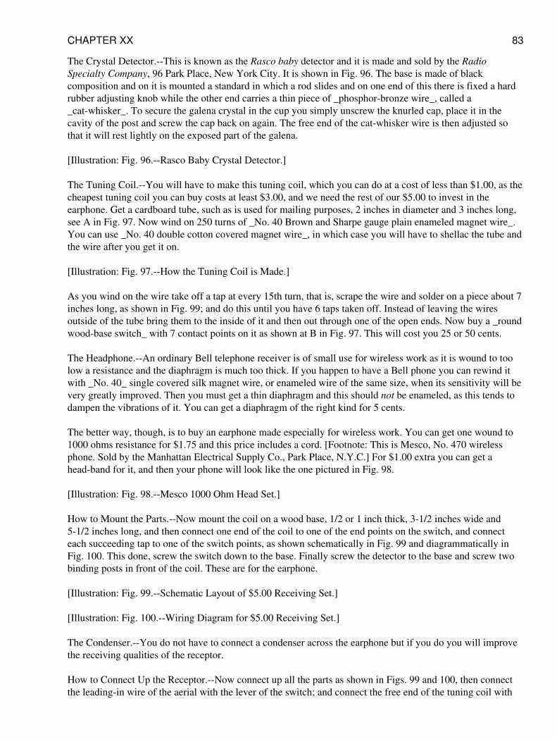
The Crystal Detector.--This is known as the Rasco baby detector and it is made and sold by the RadioSpecialty Company, 96 Park Place, New York City. It is shown in Fig. 96. The base is made of blackcomposition and on it is mounted a standard in which a rod slides and on one end of this there is fixed a hardrubber adjusting knob while the other end carries a thin piece of _phosphor-bronze wire_, called a_cat-whisker_. To secure the galena crystal in the cup you simply unscrew the knurled cap, place it in thecavity of the post and screw the cap back on again. The free end of the cat-whisker wire is then adjusted sothat it will rest lightly on the exposed part of the galena.
[Illustration: Fig. 96.--Rasco Baby Crystal Detector.]
The Tuning Coil.--You will have to make this tuning coil, which you can do at a cost of less than $1.00, as thecheapest tuning coil you can buy costs at least $3.00, and we need the rest of our $5.00 to invest in theearphone. Get a cardboard tube, such as is used for mailing purposes, 2 inches in diameter and 3 inches long,see A in Fig. 97. Now wind on 250 turns of _No. 40 Brown and Sharpe gauge plain enameled magnet wire_.You can use _No. 40 double cotton covered magnet wire_, in which case you will have to shellac the tube andthe wire after you get it on.
[Illustration: Fig. 97.--How the Tuning Coil is Made.]
As you wind on the wire take off a tap at every 15th turn, that is, scrape the wire and solder on a piece about 7inches long, as shown in Fig. 99; and do this until you have 6 taps taken off. Instead of leaving the wiresoutside of the tube bring them to the inside of it and then out through one of the open ends. Now buy a _roundwood-base switch_ with 7 contact points on it as shown at B in Fig. 97. This will cost you 25 or 50 cents.
The Headphone.--An ordinary Bell telephone receiver is of small use for wireless work as it is wound to toolow a resistance and the diaphragm is much too thick. If you happen to have a Bell phone you can rewind itwith _No. 40_ single covered silk magnet wire, or enameled wire of the same size, when its sensitivity will bevery greatly improved. Then you must get a thin diaphragm and this should not be enameled, as this tends todampen the vibrations of it. You can get a diaphragm of the right kind for 5 cents.
The better way, though, is to buy an earphone made especially for wireless work. You can get one wound to1000 ohms resistance for $1.75 and this price includes a cord. [Footnote: This is Mesco, No. 470 wirelessphone. Sold by the Manhattan Electrical Supply Co., Park Place, N.Y.C.] For $1.00 extra you can get ahead-band for it, and then your phone will look like the one pictured in Fig. 98.
[Illustration: Fig. 98.--Mesco 1000 Ohm Head Set.]
How to Mount the Parts.--Now mount the coil on a wood base, 1/2 or 1 inch thick, 3-1/2 inches wide and5-1/2 inches long, and then connect one end of the coil to one of the end points on the switch, and connecteach succeeding tap to one of the switch points, as shown schematically in Fig. 99 and diagrammatically inFig. 100. This done, screw the switch down to the base. Finally screw the detector to the base and screw twobinding posts in front of the coil. These are for the earphone.
[Illustration: Fig. 99.--Schematic Layout of $5.00 Receiving Set.]
[Illustration: Fig. 100.--Wiring Diagram for $5.00 Receiving Set.]
The Condenser.--You do not have to connect a condenser across the earphone but if you do you will improvethe receiving qualities of the receptor.
How to Connect Up the Receptor.--Now connect up all the parts as shown in Figs. 99 and 100, then connectthe leading-in wire of the aerial with the lever of the switch; and connect the free end of the tuning coil with
CHAPTER XX 83
the ground. If you have no aerial wire try hooking it up to a rain pipe that is not grounded or the steel frame ofan umbrella. For a ground you can use a water pipe, an iron pipe driven into the ground, or a hydrant. Put onyour headphone, adjust the detector and move the lever over the switch contacts until it is in adjustment andthen, if all your connections are properly made, you should be able to pick up messages.
[Illustration: Wireless Set made into a Ring, designed by Alfred G. Rinehart, of Elizabeth, New Jersey. Thislittle Receptor is a Practical Set; it will receive Messages, Concerts, etc., Measures 1" by 5/8" by 7/8". Anordinary Umbrella is used as an Aerial.]
APPENDIX
USEFUL INFORMATION
ABBREVIATIONS OF UNITS
Unit Abbreviation
ampere amp. ampere-hours amp.-hr. centimeter cm. centimeter-gram-second c.g.s. cubic centimeters cm.^3cubic inches cu. in. cycles per second ~ degrees Centigrade °C. degrees Fahrenheit °F. feet ft. foot-poundsft.-lb. grams g. henries h. inches in. kilograms kg. kilometers km. kilowatts kw. kilowatt-hours kw.-hr.kilovolt-amperes kv.-a. meters m. microfarads [Greek: mu]f. micromicrofarads [Greek: mu mu]f. millihenriesmh. millimeters mm. pounds lb. seconds sec. square centimeters cm.^2 square inches sq. in. volts v. watts w.
PREFIXES USED WITH METRIC SYSTEM UNITS
Prefix Abbreviation Meaning
micro [Greek: mu]. 1 millionth milli m. 1 thousandth centi c. 1 hundredth deci d. 1 tenth deka dk. 10 hekto h.1 hundred kilo k. 1 thousand mega m. 1 million
SYMBOLS USED FOR VARIOUS QUANTITIES
Quantity Symbol
capacitance C
conductance g
coupling co-efficient k
current, instantaneous i
current, effective value I
decrement [Greek: delta]
dielectric constant [Greek: alpha]
electric field intensity [Greek: epsilon]
electromotive force, instantaneous value E
CHAPTER XX 84
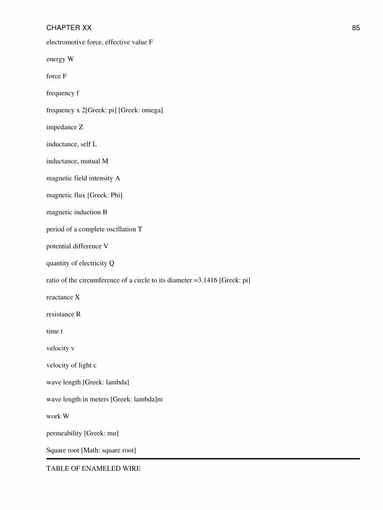
electromotive force, effective value F
energy W
force F
frequency f
frequency x 2[Greek: pi] [Greek: omega]
impedance Z
inductance, self L
inductance, mutual M
magnetic field intensity A
magnetic flux [Greek: Phi]
magnetic induction B
period of a complete oscillation T
potential difference V
quantity of electricity Q
ratio of the circumference of a circle to its diameter =3.1416 [Greek: pi]
reactance X
resistance R
time t
velocity v
velocity of light c
wave length [Greek: lambda]
wave length in meters [Greek: lambda]m
work W
permeability [Greek: mu]
Square root [Math: square root]
TABLE OF ENAMELED WIRE
CHAPTER XX 85
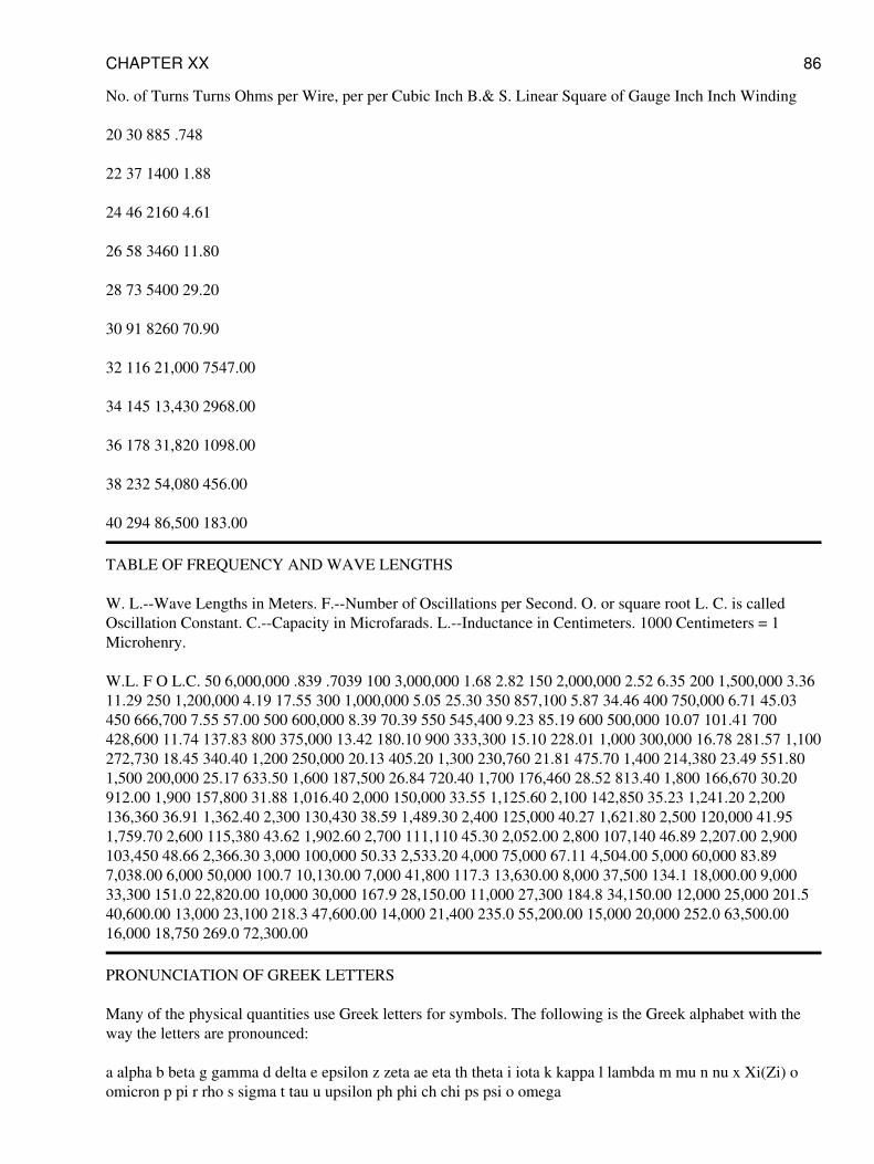
No. of Turns Turns Ohms per Wire, per per Cubic Inch B.& S. Linear Square of Gauge Inch Inch Winding
20 30 885 .748
22 37 1400 1.88
24 46 2160 4.61
26 58 3460 11.80
28 73 5400 29.20
30 91 8260 70.90
32 116 21,000 7547.00
34 145 13,430 2968.00
36 178 31,820 1098.00
38 232 54,080 456.00
40 294 86,500 183.00
TABLE OF FREQUENCY AND WAVE LENGTHS
W. L.--Wave Lengths in Meters. F.--Number of Oscillations per Second. O. or square root L. C. is calledOscillation Constant. C.--Capacity in Microfarads. L.--Inductance in Centimeters. 1000 Centimeters = 1Microhenry.
W.L. F O L.C. 50 6,000,000 .839 .7039 100 3,000,000 1.68 2.82 150 2,000,000 2.52 6.35 200 1,500,000 3.3611.29 250 1,200,000 4.19 17.55 300 1,000,000 5.05 25.30 350 857,100 5.87 34.46 400 750,000 6.71 45.03450 666,700 7.55 57.00 500 600,000 8.39 70.39 550 545,400 9.23 85.19 600 500,000 10.07 101.41 700428,600 11.74 137.83 800 375,000 13.42 180.10 900 333,300 15.10 228.01 1,000 300,000 16.78 281.57 1,100272,730 18.45 340.40 1,200 250,000 20.13 405.20 1,300 230,760 21.81 475.70 1,400 214,380 23.49 551.801,500 200,000 25.17 633.50 1,600 187,500 26.84 720.40 1,700 176,460 28.52 813.40 1,800 166,670 30.20912.00 1,900 157,800 31.88 1,016.40 2,000 150,000 33.55 1,125.60 2,100 142,850 35.23 1,241.20 2,200136,360 36.91 1,362.40 2,300 130,430 38.59 1,489.30 2,400 125,000 40.27 1,621.80 2,500 120,000 41.951,759.70 2,600 115,380 43.62 1,902.60 2,700 111,110 45.30 2,052.00 2,800 107,140 46.89 2,207.00 2,900103,450 48.66 2,366.30 3,000 100,000 50.33 2,533.20 4,000 75,000 67.11 4,504.00 5,000 60,000 83.897,038.00 6,000 50,000 100.7 10,130.00 7,000 41,800 117.3 13,630.00 8,000 37,500 134.1 18,000.00 9,00033,300 151.0 22,820.00 10,000 30,000 167.9 28,150.00 11,000 27,300 184.8 34,150.00 12,000 25,000 201.540,600.00 13,000 23,100 218.3 47,600.00 14,000 21,400 235.0 55,200.00 15,000 20,000 252.0 63,500.0016,000 18,750 269.0 72,300.00
PRONUNCIATION OF GREEK LETTERS
Many of the physical quantities use Greek letters for symbols. The following is the Greek alphabet with theway the letters are pronounced:
a alpha b beta g gamma d delta e epsilon z zeta ae eta th theta i iota k kappa l lambda m mu n nu x Xi(Zi) oomicron p pi r rho s sigma t tau u upsilon ph phi ch chi ps psi o omega
CHAPTER XX 86
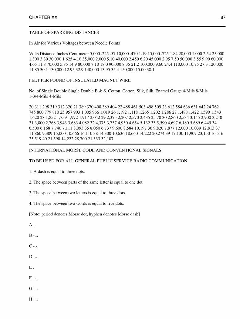
TABLE OF SPARKING DISTANCES
In Air for Various Voltages between Needle Points
Volts Distance Inches Centimeter 5,000 .225 .57 10,000 .470 1.19 15,000 .725 1.84 20,000 1.000 2.54 25,0001.300 3.30 30,000 1.625 4.10 35,000 2.000 5.10 40,000 2.450 6.20 45,000 2.95 7.50 50,000 3.55 9.90 60,0004.65 11.8 70,000 5.85 14.9 80,000 7.10 18.0 90,000 8.35 21.2 100,000 9.60 24.4 110,000 10.75 27.3 120,00011.85 30.1 130,000 12.95 32.9 140,000 13.95 35.4 150,000 15.00 38.1
FEET PER POUND OF INSULATED MAGNET WIRE
No. of Single Double Single Double B.& S. Cotton, Cotton, Silk, Silk, Enamel Gauge 4-Mils 8-Mils1-3/4-Mils 4-Mils
20 311 298 319 312 320 21 389 370 408 389 404 22 488 461 503 498 509 23 612 584 636 631 642 24 762745 800 779 810 25 957 903 1,005 966 1,019 26 1,192 1,118 1,265 1,202 1,286 27 1,488 1,422 1,590 1,5431,620 28 1,852 1,759 1,972 1,917 2,042 29 2,375 2,207 2,570 2,435 2,570 30 2,860 2,534 3,145 2,900 3,24031 3,800 2,768 3,943 3,683 4,082 32 4,375 3,737 4,950 4,654 5,132 33 5,590 4,697 6,180 5,689 6,445 346,500 6,168 7,740 7,111 8,093 35 8,050 6,737 9,600 8,584 10,197 36 9,820 7,877 12,000 10,039 12,813 3711,860 9,309 15,000 10,666 16,110 38 14,300 10,636 18,660 14,222 20,274 39 17,130 11,907 23,150 16,51625,519 40 21,590 14,222 28,700 21,333 32,107
INTERNATIONAL MORSE CODE AND CONVENTIONAL SIGNALS
TO BE USED FOR ALL GENERAL PUBLIC SERVICE RADIO COMMUNICATION
1. A dash is equal to three dots.
2. The space between parts of the same letter is equal to one dot.
3. The space between two letters is equal to three dots.
4. The space between two words is equal to five dots.
[Note: period denotes Morse dot, hyphen denotes Morse dash]
A .-
B -...
C -.-.
D -..
E .
F ..-.
G --.
H ....
CHAPTER XX 87
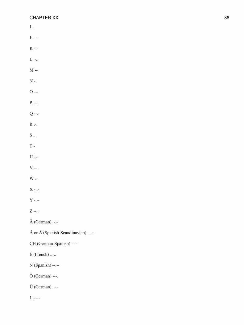
I ..
J .---
K -.-
L .-..
M --
N -.
O ---
P .--.
Q --.-
R .-.
S ...
T -
U ..-
V ...-
W .--
X -..-
Y -.--
Z --..
Ä (German) .-.-
Á or Å (Spanish-Scandinavian) .--.-
CH (German-Spanish) ----
É (French) ..-..
Ñ (Spanish) --.--
Ö (German) ---.
Ü (German) ..--
1 .----
CHAPTER XX 88
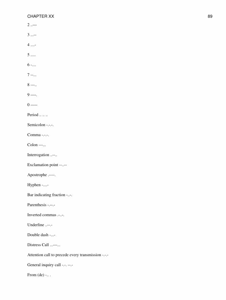
2 ..---
3 ...--
4 ....-
5 .....
6 -....
7 --...
8 ---..
9 ----.
0 -----
Period .. .. ..
Semicolon -.-.-.
Comma -.-.-.
Colon ---...
Interrogation ..--..
Exclamation point --..--
Apostrophe .----.
Hyphen -....-
Bar indicating fraction -..-.
Parenthesis -.--.-
Inverted commas .-..-.
Underline ..--.-
Double dash -...-
Distress Call ...---...
Attention call to precede every transmission -.-.-
General inquiry call -.-. --.-
From (de) -.. .
CHAPTER XX 89
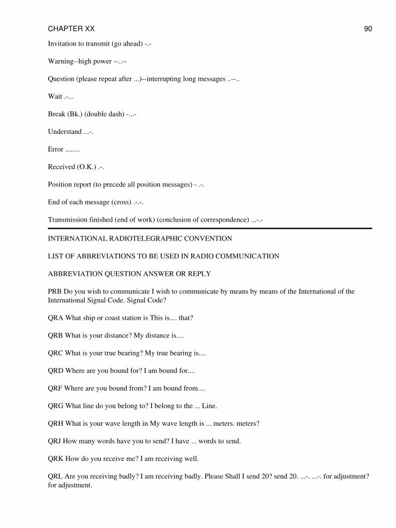
Invitation to transmit (go ahead) -.-
Warning--high power --..--
Question (please repeat after ...)--interrupting long messages ..--..
Wait .-...
Break (Bk.) (double dash) -...-
Understand ...-.
Error ........
Received (O.K.) .-.
Position report (to precede all position messages) - .-.
End of each message (cross) .-.-.
Transmission finished (end of work) (conclusion of correspondence) ...-.-
INTERNATIONAL RADIOTELEGRAPHIC CONVENTION
LIST OF ABBREVIATIONS TO BE USED IN RADIO COMMUNICATION
ABBREVIATION QUESTION ANSWER OR REPLY
PRB Do you wish to communicate I wish to communicate by means by means of the International of theInternational Signal Code. Signal Code?
QRA What ship or coast station is This is.... that?
QRB What is your distance? My distance is....
QRC What is your true bearing? My true bearing is....
QRD Where are you bound for? I am bound for....
QRF Where are you bound from? I am bound from....
QRG What line do you belong to? I belong to the ... Line.
QRH What is your wave length in My wave length is ... meters. meters?
QRJ How many words have you to send? I have ... words to send.
QRK How do you receive me? I am receiving well.
QRL Are you receiving badly? I am receiving badly. Please Shall I send 20? send 20. ...-. ...-. for adjustment?for adjustment.
CHAPTER XX 90
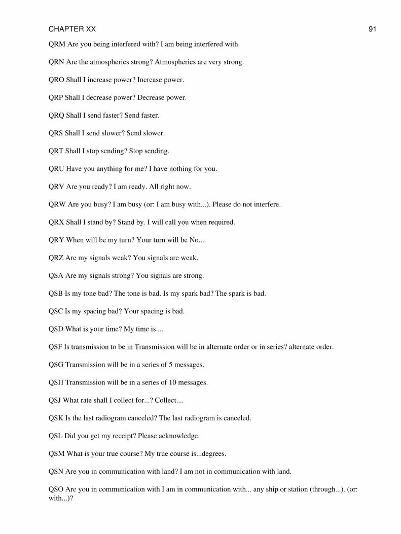
QRM Are you being interfered with? I am being interfered with.
QRN Are the atmospherics strong? Atmospherics are very strong.
QRO Shall I increase power? Increase power.
QRP Shall I decrease power? Decrease power.
QRQ Shall I send faster? Send faster.
QRS Shall I send slower? Send slower.
QRT Shall I stop sending? Stop sending.
QRU Have you anything for me? I have nothing for you.
QRV Are you ready? I am ready. All right now.
QRW Are you busy? I am busy (or: I am busy with...). Please do not interfere.
QRX Shall I stand by? Stand by. I will call you when required.
QRY When will be my turn? Your turn will be No....
QRZ Are my signals weak? You signals are weak.
QSA Are my signals strong? You signals are strong.
QSB Is my tone bad? The tone is bad. Is my spark bad? The spark is bad.
QSC Is my spacing bad? Your spacing is bad.
QSD What is your time? My time is....
QSF Is transmission to be in Transmission will be in alternate order or in series? alternate order.
QSG Transmission will be in a series of 5 messages.
QSH Transmission will be in a series of 10 messages.
QSJ What rate shall I collect for...? Collect....
QSK Is the last radiogram canceled? The last radiogram is canceled.
QSL Did you get my receipt? Please acknowledge.
QSM What is your true course? My true course is...degrees.
QSN Are you in communication with land? I am not in communication with land.
QSO Are you in communication with I am in communication with... any ship or station (through...). (or:with...)?
CHAPTER XX 91
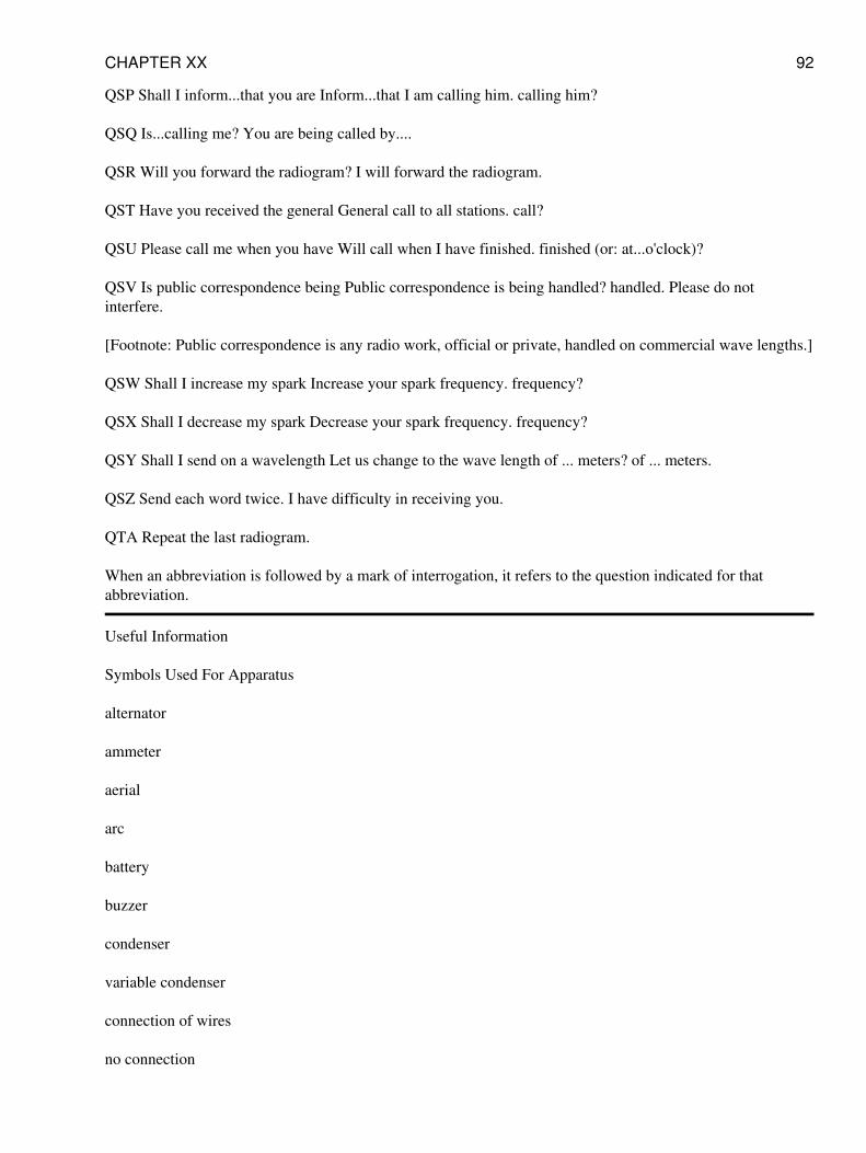
QSP Shall I inform...that you are Inform...that I am calling him. calling him?
QSQ Is...calling me? You are being called by....
QSR Will you forward the radiogram? I will forward the radiogram.
QST Have you received the general General call to all stations. call?
QSU Please call me when you have Will call when I have finished. finished (or: at...o'clock)?
QSV Is public correspondence being Public correspondence is being handled? handled. Please do notinterfere.
[Footnote: Public correspondence is any radio work, official or private, handled on commercial wave lengths.]
QSW Shall I increase my spark Increase your spark frequency. frequency?
QSX Shall I decrease my spark Decrease your spark frequency. frequency?
QSY Shall I send on a wavelength Let us change to the wave length of ... meters? of ... meters.
QSZ Send each word twice. I have difficulty in receiving you.
QTA Repeat the last radiogram.
When an abbreviation is followed by a mark of interrogation, it refers to the question indicated for thatabbreviation.
Useful Information
Symbols Used For Apparatus
alternator
ammeter
aerial
arc
battery
buzzer
condenser
variable condenser
connection of wires
no connection
CHAPTER XX 92
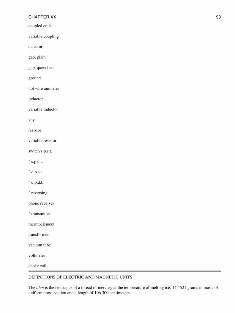
coupled coils
variable coupling
detector
gap, plain
gap, quenched
ground
hot wire ammeter
inductor
variable inductor
key
resistor
variable resistor
switch s.p.s.t.
" s.p.d.t.
" d.p.s.t.
" d.p.d.t.
" reversing
phone receiver
" transmitter
thermoelement
transformer
vacuum tube
voltmeter
choke coil
DEFINITIONS OF ELECTRIC AND MAGNETIC UNITS
The ohm is the resistance of a thread of mercury at the temperature of melting ice, 14.4521 grams in mass, ofuniform cross-section and a length of 106.300 centimeters.
CHAPTER XX 93
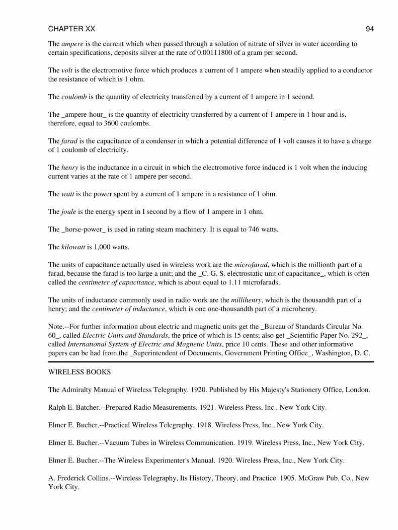
The ampere is the current which when passed through a solution of nitrate of silver in water according tocertain specifications, deposits silver at the rate of 0.00111800 of a gram per second.
The volt is the electromotive force which produces a current of 1 ampere when steadily applied to a conductorthe resistance of which is 1 ohm.
The coulomb is the quantity of electricity transferred by a current of 1 ampere in 1 second.
The _ampere-hour_ is the quantity of electricity transferred by a current of 1 ampere in 1 hour and is,therefore, equal to 3600 coulombs.
The farad is the capacitance of a condenser in which a potential difference of 1 volt causes it to have a chargeof 1 coulomb of electricity.
The henry is the inductance in a circuit in which the electromotive force induced is 1 volt when the inducingcurrent varies at the rate of 1 ampere per second.
The watt is the power spent by a current of 1 ampere in a resistance of 1 ohm.
The joule is the energy spent in I second by a flow of 1 ampere in 1 ohm.
The _horse-power_ is used in rating steam machinery. It is equal to 746 watts.
The kilowatt is 1,000 watts.
The units of capacitance actually used in wireless work are the microfarad, which is the millionth part of afarad, because the farad is too large a unit; and the _C. G. S. electrostatic unit of capacitance_, which is oftencalled the centimeter of capacitance, which is about equal to 1.11 microfarads.
The units of inductance commonly used in radio work are the millihenry, which is the thousandth part of ahenry; and the centimeter of inductance, which is one one-thousandth part of a microhenry.
Note.--For further information about electric and magnetic units get the _Bureau of Standards Circular No.60_, called Electric Units and Standards, the price of which is 15 cents; also get _Scientific Paper No. 292_,called International System of Electric and Magnetic Units, price 10 cents. These and other informativepapers can be had from the _Superintendent of Documents, Government Printing Office_, Washington, D. C.
WIRELESS BOOKS
The Admiralty Manual of Wireless Telegraphy. 1920. Published by His Majesty's Stationery Office, London.
Ralph E. Batcher.--Prepared Radio Measurements. 1921. Wireless Press, Inc., New York City.
Elmer E. Bucher.--Practical Wireless Telegraphy. 1918. Wireless Press, Inc., New York City.
Elmer E. Bucher.--Vacuum Tubes in Wireless Communication. 1919. Wireless Press, Inc., New York City.
Elmer E. Bucher.--The Wireless Experimenter's Manual. 1920. Wireless Press, Inc., New York City.
A. Frederick Collins.--Wireless Telegraphy, Its History, Theory, and Practice. 1905. McGraw Pub. Co., NewYork City.
CHAPTER XX 94
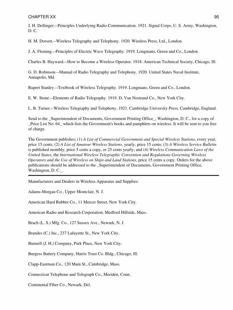
J. H. Dellinger.--Principles Underlying Radio Communication. 1921. Signal Corps, U. S. Army, Washington,D. C.
H. M. Dorsett.--Wireless Telegraphy and Telephony. 1920. Wireless Press, Ltd., London.
J. A. Fleming.--Principles of Electric Wave Telegraphy. 1919. Longmans, Green and Co., London.
Charles B. Hayward.--How to Become a Wireless Operator. 1918. American Technical Society, Chicago, Ill.
G. D. Robinson.--Manual of Radio Telegraphy and Telephony. 1920. United States Naval Institute,Annapolis, Md.
Rupert Stanley.--Textbook of Wireless Telegraphy. 1919. Longmans, Green and Co., London.
E. W. Stone.--Elements of Radio Telegraphy. 1919. D, Van Nostrand Co., New York City.
L. B. Turner.--Wireless Telegraphy and Telephony. 1921. Cambridge University Press. Cambridge, England.
Send to the _Superintendent of Documents, Government Printing Office_, Washington, D. C., for a copy of_Price List No. 64_ which lists the Government's books and pamphlets on wireless. It will be sent to you freeof charge.
The Government publishes; (1) A List of Commercial Government and Special Wireless Stations, every year,price 15 cents; (2) A List of Amateur Wireless Stations, yearly, price 15 cents; (3) A Wireless Service Bulletinis published monthly, price 5 cents a copy, or 25 cents yearly; and (4) Wireless Communication Laws of theUnited States, the International Wireless Telegraphic Convention and Regulations Governing WirelessOperators and the Use of Wireless on Ships and Land Stations, price 15 cents a copy. Orders for the abovepublications should be addressed to the _Superintendent of Documents, Government Printing Office,Washington, D. C._
Manufacturers and Dealers in Wireless Apparatus and Supplies:
Adams-Morgan Co., Upper Montclair, N. J.
American Hard Rubber Co., 11 Mercer Street, New York City.
American Radio and Research Corporation, Medford Hillside, Mass.
Brach (L. S.) Mfg. Co., 127 Sussex Ave., Newark, N. J.
Brandes (C.) Inc., 237 Lafayette St., New York City.
Bunnell (J. H.) Company, Park Place, New York City.
Burgess Battery Company, Harris Trust Co. Bldg., Chicago, Ill.
Clapp-Eastman Co., 120 Main St., Cambridge, Mass.
Connecticut Telephone and Telegraph Co., Meriden, Conn.
Continental Fiber Co., Newark, Del.
CHAPTER XX 95
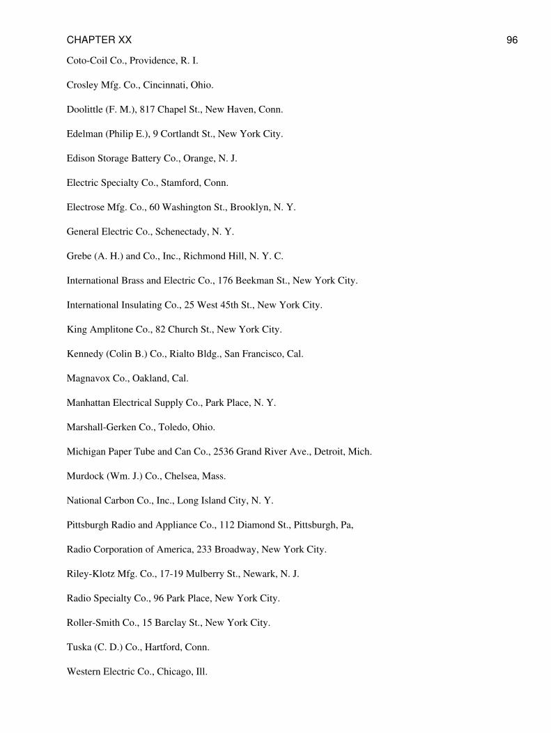
Coto-Coil Co., Providence, R. I.
Crosley Mfg. Co., Cincinnati, Ohio.
Doolittle (F. M.), 817 Chapel St., New Haven, Conn.
Edelman (Philip E.), 9 Cortlandt St., New York City.
Edison Storage Battery Co., Orange, N. J.
Electric Specialty Co., Stamford, Conn.
Electrose Mfg. Co., 60 Washington St., Brooklyn, N. Y.
General Electric Co., Schenectady, N. Y.
Grebe (A. H.) and Co., Inc., Richmond Hill, N. Y. C.
International Brass and Electric Co., 176 Beekman St., New York City.
International Insulating Co., 25 West 45th St., New York City.
King Amplitone Co., 82 Church St., New York City.
Kennedy (Colin B.) Co., Rialto Bldg., San Francisco, Cal.
Magnavox Co., Oakland, Cal.
Manhattan Electrical Supply Co., Park Place, N. Y.
Marshall-Gerken Co., Toledo, Ohio.
Michigan Paper Tube and Can Co., 2536 Grand River Ave., Detroit, Mich.
Murdock (Wm. J.) Co., Chelsea, Mass.
National Carbon Co., Inc., Long Island City, N. Y.
Pittsburgh Radio and Appliance Co., 112 Diamond St., Pittsburgh, Pa,
Radio Corporation of America, 233 Broadway, New York City.
Riley-Klotz Mfg. Co., 17-19 Mulberry St., Newark, N. J.
Radio Specialty Co., 96 Park Place, New York City.
Roller-Smith Co., 15 Barclay St., New York City.
Tuska (C. D.) Co., Hartford, Conn.
Western Electric Co., Chicago, Ill.
CHAPTER XX 96
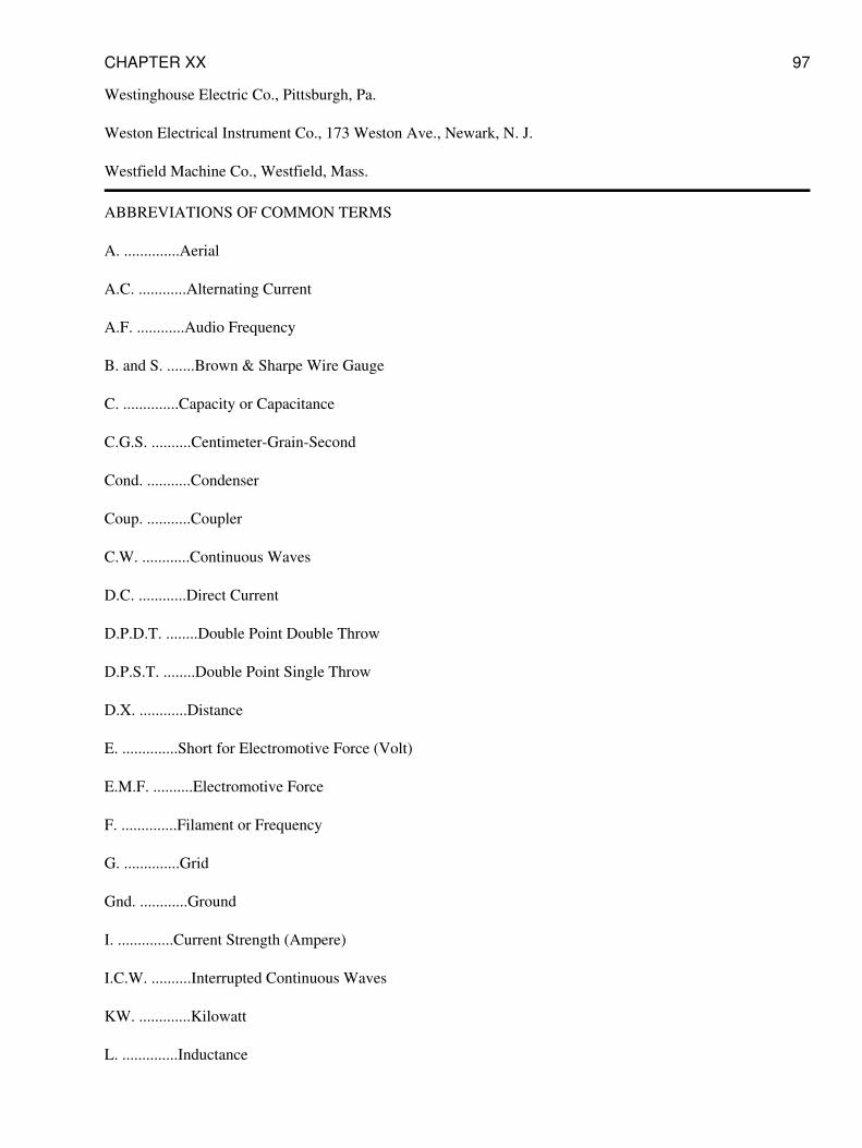
Westinghouse Electric Co., Pittsburgh, Pa.
Weston Electrical Instrument Co., 173 Weston Ave., Newark, N. J.
Westfield Machine Co., Westfield, Mass.
ABBREVIATIONS OF COMMON TERMS
A. ..............Aerial
A.C. ............Alternating Current
A.F. ............Audio Frequency
B. and S. .......Brown & Sharpe Wire Gauge
C. ..............Capacity or Capacitance
C.G.S. ..........Centimeter-Grain-Second
Cond. ...........Condenser
Coup. ...........Coupler
C.W. ............Continuous Waves
D.C. ............Direct Current
D.P.D.T. ........Double Point Double Throw
D.P.S.T. ........Double Point Single Throw
D.X. ............Distance
E. ..............Short for Electromotive Force (Volt)
E.M.F. ..........Electromotive Force
F. ..............Filament or Frequency
G. ..............Grid
Gnd. ............Ground
I. ..............Current Strength (Ampere)
I.C.W. ..........Interrupted Continuous Waves
KW. .............Kilowatt
L. ..............Inductance
CHAPTER XX 97
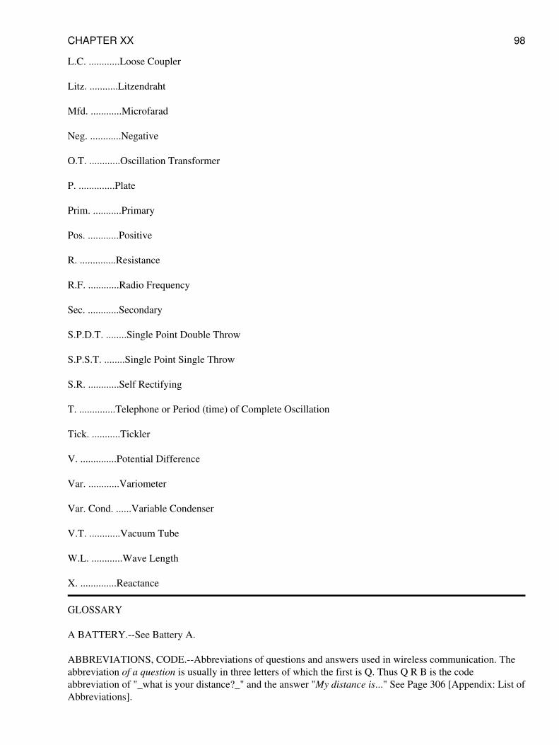
L.C. ............Loose Coupler
Litz. ...........Litzendraht
Mfd. ............Microfarad
Neg. ............Negative
O.T. ............Oscillation Transformer
P. ..............Plate
Prim. ...........Primary
Pos. ............Positive
R. ..............Resistance
R.F. ............Radio Frequency
Sec. ............Secondary
S.P.D.T. ........Single Point Double Throw
S.P.S.T. ........Single Point Single Throw
S.R. ............Self Rectifying
T. ..............Telephone or Period (time) of Complete Oscillation
Tick. ...........Tickler
V. ..............Potential Difference
Var. ............Variometer
Var. Cond. ......Variable Condenser
V.T. ............Vacuum Tube
W.L. ............Wave Length
X. ..............Reactance
GLOSSARY
A BATTERY.--See Battery A.
ABBREVIATIONS, CODE.--Abbreviations of questions and answers used in wireless communication. Theabbreviation of a question is usually in three letters of which the first is Q. Thus Q R B is the codeabbreviation of "_what is your distance?_" and the answer "My distance is..." See Page 306 [Appendix: List ofAbbreviations].
CHAPTER XX 98
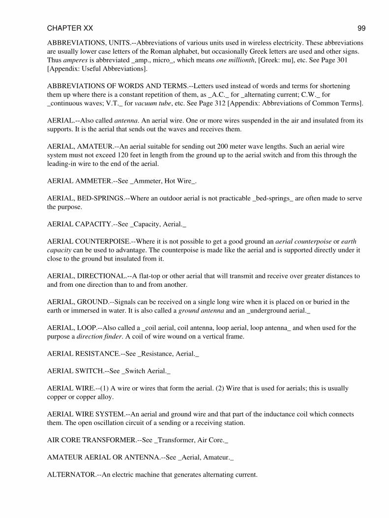
ABBREVIATIONS, UNITS.--Abbreviations of various units used in wireless electricity. These abbreviationsare usually lower case letters of the Roman alphabet, but occasionally Greek letters are used and other signs.Thus amperes is abbreviated _amp., micro_, which means one millionth, [Greek: mu], etc. See Page 301[Appendix: Useful Abbreviations].
ABBREVIATIONS OF WORDS AND TERMS.--Letters used instead of words and terms for shorteningthem up where there is a constant repetition of them, as _A.C._ for _alternating current; C.W._ for_continuous waves; V.T._ for vacuum tube, etc. See Page 312 [Appendix: Abbreviations of Common Terms].
AERIAL.--Also called antenna. An aerial wire. One or more wires suspended in the air and insulated from itssupports. It is the aerial that sends out the waves and receives them.
AERIAL, AMATEUR.--An aerial suitable for sending out 200 meter wave lengths. Such an aerial wiresystem must not exceed 120 feet in length from the ground up to the aerial switch and from this through theleading-in wire to the end of the aerial.
AERIAL AMMETER.--See _Ammeter, Hot Wire_.
AERIAL, BED-SPRINGS.--Where an outdoor aerial is not practicable _bed-springs_ are often made to servethe purpose.
AERIAL CAPACITY.--See _Capacity, Aerial._
AERIAL COUNTERPOISE.--Where it is not possible to get a good ground an aerial counterpoise or earthcapacity can be used to advantage. The counterpoise is made like the aerial and is supported directly under itclose to the ground but insulated from it.
AERIAL, DIRECTIONAL.--A flat-top or other aerial that will transmit and receive over greater distances toand from one direction than to and from another.
AERIAL, GROUND.--Signals can be received on a single long wire when it is placed on or buried in theearth or immersed in water. It is also called a ground antenna and an _underground aerial._
AERIAL, LOOP.--Also called a _coil aerial, coil antenna, loop aerial, loop antenna_ and when used for thepurpose a direction finder. A coil of wire wound on a vertical frame.
AERIAL RESISTANCE.--See _Resistance, Aerial._
AERIAL SWITCH.--See _Switch Aerial._
AERIAL WIRE.--(1) A wire or wires that form the aerial. (2) Wire that is used for aerials; this is usuallycopper or copper alloy.
AERIAL WIRE SYSTEM.--An aerial and ground wire and that part of the inductance coil which connectsthem. The open oscillation circuit of a sending or a receiving station.
AIR CORE TRANSFORMER.--See _Transformer, Air Core._
AMATEUR AERIAL OR ANTENNA.--See _Aerial, Amateur._
ALTERNATOR.--An electric machine that generates alternating current.
CHAPTER XX 99
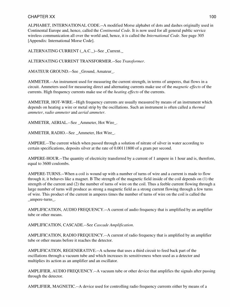
ALPHABET, INTERNATIONAL CODE.--A modified Morse alphabet of dots and dashes originally used inContinental Europe and, hence, called the Continental Code. It is now used for all general public servicewireless communication all over the world and, hence, it is called the International Code. See page 305[Appendix: International Morse Code].
ALTERNATING CURRENT (_A.C._)--See _Current._
ALTERNATING CURRENT TRANSFORMER.--See Transformer.
AMATEUR GROUND.--See _Ground, Amateur_.
AMMETER.--An instrument used for measuring the current strength, in terms of amperes, that flows in acircuit. Ammeters used for measuring direct and alternating currents make use of the magnetic effects of thecurrents. High frequency currents make use of the heating effects of the currents.
AMMETER, HOT-WIRE.--High frequency currents are usually measured by means of an instrument whichdepends on heating a wire or metal strip by the oscillations. Such an instrument is often called a thermalammeter, radio ammeter and aerial ammeter.
AMMETER, AERIAL.--See _Ammeter, Hot Wire_.
AMMETER, RADIO.--See _Ammeter, Hot Wire_.
AMPERE.--The current which when passed through a solution of nitrate of silver in water according tocertain specifications, deposits silver at the rate of 0.00111800 of a gram per second.
AMPERE-HOUR.--The quantity of electricity transferred by a current of 1 ampere in 1 hour and is, therefore,equal to 3600 coulombs.
AMPERE-TURNS.--When a coil is wound up with a number of turns of wire and a current is made to flowthrough it, it behaves like a magnet. B The strength of the magnetic field inside of the coil depends on (1) thestrength of the current and (2) the number of turns of wire on the coil. Thus a feeble current flowing through alarge number of turns will produce as strong a magnetic field as a strong current flowing through a few turnsof wire. This product of the current in amperes times the number of turns of wire on the coil is called the_ampere-turns_.
AMPLIFICATION, AUDIO FREQUENCY.--A current of audio frequency that is amplified by an amplifiertube or other means.
AMPLIFICATION, CASCADE.--See Cascade Amplification.
AMPLIFICATION, RADIO FREQUENCY.--A current of radio frequency that is amplified by an amplifiertube or other means before it reaches the detector.
AMPLIFICATION, REGENERATIVE.--A scheme that uses a third circuit to feed back part of theoscillations through a vacuum tube and which increases its sensitiveness when used as a detector andmultiplies its action as an amplifier and an oscillator.
AMPLIFIER, AUDIO FREQUENCY.--A vacuum tube or other device that amplifies the signals after passingthrough the detector.
AMPLIFIER, MAGNETIC.--A device used for controlling radio frequency currents either by means of a
CHAPTER XX 100
telegraph key or a microphone transmitter. The controlling current flows through a separate circuit from thatof the radio current and a fraction of an ampere will control several amperes in the aerial wire.
AMPLIFIERS, MULTI-STAGE.--A receiving set using two or more amplifiers. Also called cascadeamplification.
AMPLIFIER, VACUUM TUBE.--A vacuum tube that is used either to amplify the radio frequency currentsor the audio frequency currents.
AMPLITUDE OF WAVE.--The greatest distance that a point moves from its position of rest.
AMPLIFYING TRANSFORMER, AUDIO.--See _Transformer, Audio Amplifying_.
AMPLIFYING MODULATOR VACUUM TUBE.--See _Vacuum Tube, Amplifying Modulator_.
AMPLIFYING TRANSFORMER RADIO.--See _Transformer, Radio Amplifying_.
ANTENNA, AMATEUR.--See _Aerial, Amateur_.
ANTENNA SWITCH.--See _Switch, Aerial_.
APPARATUS SYMBOLS.--See _Symbols, Apparatus_.
ARMSTRONG CIRCUIT.--See _Circuit, Armstrong_.
ATMOSPHERICS.--Same as Static, which see.
ATTENUATION.--In Sending wireless telegraph and telephone messages the amplitude of the electric wavesis damped out as the distance increases. This is called attenuation and it increases as the frequency isincreased. This is the reason why short wave lengths will not carry as far as long wave lengths.
AUDIO FREQUENCY AMPLIFIER.--See _Amplifier, Audio Frequency_.
AUDIO FREQUENCY AMPLIFICATION.--See _Amplification, Audio Frequency_.
AUDIBILITY METER.--See _Meter, Audibility_.
AUDIO FREQUENCY.--See _Frequency, Audio_.
AUDIO FREQUENCY CURRENT.--See _Current, Audio Frequency_.
AUDION.--An early trade name given to the vacuum tube detector.
AUTODYNE RECEPTOR.--See _Receptor, Autodyne_.
AUTO TRANSFORMER.--See _Transformer, Auto_.
BAKELITE.--A manufactured insulating compound.
B BATTERY.--See Battery B.
BAND, WAVE LENGTH.--See Wave Length Band.
CHAPTER XX 101
BASKET WOUND COILS.--See _Coils, Inductance_.
BATTERY, A.--The 6-volt storage battery used to heat the filament of a vacuum tube, detector or amplifier.
BATTERY, B.--The 22-1/2-volt dry cell battery used to energize the plate of a vacuum tube detector oramplifier.
BATTERY, BOOSTER.--This is the battery that is connected in series with the crystal detector.
BATTERY, C.--A small dry cell battery sometimes used to give the grid of a vacuum tube detector a biaspotential.
BATTERY, EDISON STORAGE.--A storage battery in which the elements are made of nickel and iron andimmersed in an alkaline electrolyte.
BATTERY, LEAD STORAGE.--A storage battery in which the elements are made of lead and immersed inan acid electrolyte.
BATTERY POLES.--See _Poles, Battery_.
BATTERY, PRIMARY.--A battery that generates current by chemical action.
BATTERY, STORAGE.--A battery that develops a current after it has been charged.
BEAT RECEPTION.--See Heterodyne Reception.
BED SPRINGS AERIAL.--See _Aerial, Bed Springs_.
BLUB BLUB.--Over modulation in wireless telephony.
BROAD WAVE.--See _Wave, Broad_.
BRUSH DISCHARGE.--See Discharge.
BUZZER MODULATION.--See _Modulation, Buzzer_.
BLUE GLOW DISCHARGE.--See Discharge.
BOOSTER BATTERY.--See _Battery, Booster_.
BROADCASTING.--Sending out intelligence and music from a central station for the benefit of all who livewithin range of it and who have receiving sets.
CAPACITANCE.--Also called by the older name of capacity. The capacity of a condenser, inductance coil orother device capable of retaining a charge of electricity. Capacitance is measured in terms of the microfarad.
CAPACITIVE COUPLING.--See _Coupling, Capacitive_.
CAPACITY.--Any object that will retain a charge of electricity; hence an aerial wire, a condenser or a metalplate is sometimes called a capacity.
CAPACITY, AERIAL.--The amount to which an aerial wire system can be charged. The capacitance of a
CHAPTER XX 102
small amateur aerial is from 0.0002 to 0.0005 microfarad.
CAPACITY, DISTRIBUTED.--A coil of wire not only has inductance, but also a certain small capacitance.Coils wound with their turns parallel and having a number of layers have a bunched capacitance whichproduces untoward effects in oscillation circuits. In honeycomb and other stagger wound coils the capacitanceis more evenly distributed.
CAPACITY REACTANCE.--See _Reactance, Capacity_.
CAPACITY UNIT.--See Farad.
CARBON RHEOSTATS.--See _Rheostat, Carbon_.
CARBORUNDUM DETECTOR.--See Detector.
CARRIER CURRENT TELEPHONY.--See _Wired-Wireless_.
CARRIER FREQUENCY.--See _Frequency, Carrier_.
CARRIER FREQUENCY TELEPHONY.--See _Wired-Wireless_.
CASCADE AMPLIFICATION.--Two or more amplifying tubes hooked up in a receiving set.
CAT WHISKER CONTACT.--A long, thin wire which makes contact with the crystal of a detector.
CENTIMETER OF CAPACITANCE.--Equal to 1.11 microfarads.
CENTIMETER OF INDUCTANCE.--Equal to one one-thousandth part of a microhenry.
CELLULAR COILS.--See _Coils, Inductance_.
C.G.S. ELECTROSTATIC UNIT OF CAPACITANCE.--See Centimeter of Capacitance.
CHARACTERISTICS.--The special behavior of a device, such as an aerial, a detector tube, etc.
CHARACTERISTICS, GRID.--See Grid Characteristics.
CHOKE COILS.--Coils that prevent the high voltage oscillations from surging back into the transformer andbreaking down the insulation.
CHOPPER MODULATION.--See _Modulation, Chopper_.
CIRCUIT.--Any electrical conductor through which a current can flow. A low voltage current requires a loopof wire or other conductor both ends of which are connected to the source of current before it can flow. A highfrequency current will surge in a wire which is open at both ends like the aerial.
Closed Circuit.--A circuit that is continuous.
Open Circuit.--A conductor that is not continuous.
Coupled Circuits.--Open and closed circuits connected together by inductance coils, condensers or resistances.See coupling.
CHAPTER XX 103
Close Coupled Circuits.--Open and closed circuits connected directly together with a single inductance coil.
Loose Coupled Circuits.--Opened and closed currents connected together inductively by means of atransformer.
Stand-by Circuits.--Also called _pick-up_ circuits. When listening-in for possible calls from a number ofstations, a receiver is used which will respond to a wide band of wave lengths.
Armstrong Circuits.--The regenerative circuit invented by Major E. H. Armstrong.
CLOSE COUPLED CIRCUITS.--See _Currents, Close Coupled_.
CLOSED CIRCUIT.--See _Circuit, Closed_.
CLOSED CORE TRANSFORMER.--See _Transformer, Closed Core_.
CODE.--
Continental.--Same as International.
International.--On the continent of Europe land lines use the Continental Morse alphabetic code. This codehas come to be used throughout the world for wireless telegraphy and hence it is now called the Internationalcode. It is given on Page 305. [Appendix: International Morse Code].
Morse.--The code devised by Samuel F. B. Morse and which is used on the land lines in the U. S.
National Electric.--A set of rules and requirements devised by the National Board of Fire Underwriters forthe electrical installations in buildings on which insurance companies carry risks. This code also covers therequirements for wireless installations. A copy may be had from the National Board of Fire Underwriters,New York City, or from your insurance agent.
National Electric Safety.--The Bureau of Standards, Washington, D. C., have investigated the precautionswhich should be taken for the safe operation of all electric equipment. A copy of the _Bureau of StandardsHandbook No. 3_ can be had for 40 cents from the Superintendent of Documents.
COEFFICIENT OF COUPLING.--See _Coupling, Coefficient of_.
COIL AERIAL.--See _Aerial, Loop_.
COIL ANTENNA.--See _Aerial, Loop_.
COIL, INDUCTION.--An apparatus for changing low voltage direct currents into high voltage, low frequencyalternating currents. When fitted with a spark gap the high voltage, low frequency currents are converted intohigh voltage, high frequency currents. It is then also called a spark coil and a Ruhmkorff coil.
COIL, LOADING.--A coil connected in the aerial or closed oscillation circuit so that longer wave lengths canbe received.
COIL, REPEATING.--See Repeating Coil.
COIL, ROTATING.--One which rotates on a shaft instead of sliding as in a loose coupler. The rotor of avariometer or variocoupler is a rotating coil.
CHAPTER XX 104
COILS, INDUCTANCE.--These are the tuning coils used for sending and receiving sets. For sending setsthey are formed of one and two coils, a single sending coil is generally called a tuning inductance coil, while atwo-coil tuner is called an oscillation transformer. Receiving tuning coils are made with a single layer, singlecoil, or a pair of coils, when it is called an oscillation transformer. Some tuning inductance coils have morethan one layer, they are then called lattice wound, cellular, basket wound, honeycomb, _duo-lateral_, staggerwound, _spider-web_ and slab coils.
COMMERCIAL FREQUENCY.--See _Frequency, Commercial_.
CONDENSER, AERIAL SERIES.--A condenser placed in the aerial wire system to cut down the wavelength.
CONDENSER, VERNIER.--A small variable condenser used for receiving continuous waves where verysharp tuning is desired.
CONDENSER.--All conducting objects with their insulation form capacities, but a condenser is understood tomean two sheets or plates of metal placed closely together but separated by some insulating material.
Adjustable Condenser.--Where two or more condensers can be coupled together by means of plugs, switchesor other devices.
Aerial Condenser.--A condenser connected in the aerial.
Air Condenser.--Where air only separates the sheets of metal.
By-Pass Condenser.--A condenser connected in the transmitting currents so that the high frequency currentscannot flow back through the power circuit.
Filter Condenser.--A condenser of large capacitance used in combination with a filter reactor for smoothingout the pulsating direct currents as they come from the rectifier.
Fixed Condenser.--Where the plates are fixed relatively to one another.
Grid Condenser.--A condenser connected in series with the grid lead.
Leyden Jar Condenser.--Where glass jars are used.
Mica Condenser.--Where mica is used.
Oil Condenser.--Where the plates are immersed in oil.
Paper Condenser.--Where paper is used as the insulating material.
Protective.--A condenser of large capacity connected across the low voltage supply circuit of a transmitter toform a by-path of kick-back oscillations.
Variable Condenser.--Where alternate plates can be moved and so made to interleave more or less with a setof fixed plates.
Vernier.--A small condenser with a vernier on it so that it can be very accurately varied. It is connected inparallel with the variable condenser used in the primary circuit and is used for the reception of continuouswaves where sharp tuning is essential.
CHAPTER XX 105
CONDENSITE.--A manufactured insulating compound.
CONDUCTIVITY.--The conductance of a given length of wire of uniform cross section. The reciprocal ofresistivity.
CONTACT DETECTORS.--See _Detectors, Contact_.
CONTINENTAL CODE.--See _Code, Continental_.
COULOMB.--The quantity of electricity transferred by a current of 1 ampere in 1 second.
CONVECTIVE DISCHARGE.--See Discharge.
CONVENTIONAL SIGNALS.--See _Signals, Conventional_.
COUNTER ELECTROMOTIVE FORCE.--See _Electromotive Force, Counter_.
COUNTERPOISE. A duplicate of the aerial wire that is raised a few feet above the earth and insulated fromit. Usually no connection is made with the earth itself.
COUPLED CIRCUITS.--See _Circuit, Coupled_.
COUPLING.--When two oscillation circuits are connected together either by the magnetic field of aninductance coil, or by the electrostatic field of a condenser.
COUPLING, CAPACITIVE.--Oscillation circuits when connected together by condensers instead ofinductance coils.
COUPLING, COEFFICIENT OF.--The measure of the closeness of the coupling between two coils.
COUPLING, INDUCTIVE.--Oscillation circuits when connected together by inductance coils.
COUPLING, RESISTANCE.--Oscillation circuits connected together by a resistance.
CRYSTAL RECTIFIER.--A crystal detector.
CURRENT, ALTERNATING (A.C.).--A low frequency current that surges to and fro in a circuit.
CURRENT, AUDIO FREQUENCY.--A current whose frequency is low enough to be heard in a telephonereceiver. Such a current usually has a frequency of between 200 and 2,000 cycles per second.
CURRENT, PLATE.--The current which flows between the filament and the plate of a vacuum tube.
CURRENT, PULSATING.--A direct current whose voltage varies from moment to moment.
CURRENT, RADIO FREQUENCY.--A current whose frequency is so high it cannot be heard in a telephonereceiver. Such a current may have a frequency of from 20,000 to 10,000,000 per second.
CURRENTS, HIGH FREQUENCY.--(1) Currents that oscillate from 10,000 to 300,000,000 times persecond. (2) Electric oscillations.
CURRENTS, HIGH POTENTIAL.--(1) Currents that have a potential of more than 10,000 volts. (2) High
CHAPTER XX 106
voltage currents.
CYCLE.--(1) A series of changes which when completed are again at the starting point. (2) A period of timeat the end of which an alternating or oscillating current repeats its original direction of flow.
DAMPING.--The degree to which the energy of an electric oscillation is reduced. In an open circuit theenergy of an oscillation set up by a spark gap is damped out in a few swings, while in a closed circuit it isgreatly prolonged, the current oscillating 20 times or more before the energy is dissipated by the sum of theresistances of the circuit.
DECREMENT.--The act or process of gradually becoming less.
DETECTOR.--Any device that will (1) change the oscillations set up by the incoming waves into directcurrent, that is which will rectify them, or (2) that will act as a relay.
Carborundum.--One that uses a carborundum crystal for the sensitive element. Carborundum is a crystallinesilicon carbide formed in the electric furnace.
Cat Whisker Contact.--See Cat Whisker Contact.
Chalcopyrite.--Copper pyrites. A brass colored mineral used as a crystal for detectors. See Zincite.
Contact.--A crystal detector. Any kind of a detector in which two dissimilar but suitable solids make contact.
Ferron.--A detector in which iron pyrites are used as the sensitive element.
Galena.--A detector that uses a galena crystal for the rectifying element.
Iron Pyrites.--A detector that uses a crystal of iron pyrites for its sensitive element.
Molybdenite.--A detector that uses a crystal of sulphide of molybdenum for the sensitive element.
Perikon.--A detector in which a bornite crystal makes contact with a zincite crystal.
Silicon.--A detector that uses a crystal of silicon for its sensitive element.
Vacuum Tube.--A vacuum tube (which see) used as a detector.
Zincite.--A detector in which a crystal of zincite is used as the sensitive element.
DE TUNING.--A method of signaling by sustained oscillations in which the key when pressed down cuts outeither some of the inductance or some of the capacity and hence greatly changes the wave length.
DIELECTRIC.--An insulating material between two electrically charged plates in which there is set up anelectric strain, or displacement.
DIELECTRIC STRAIN.--The electric displacement in a dielectric.
DIRECTIONAL AERIAL.--See _Aerial, Directional_.
DIRECTION FINDER.--See _Aerial, Loop_.
CHAPTER XX 107
DISCHARGE.--(1) A faintly luminous discharge that takes place from the positive pointed terminal of aninduction coil, or other high potential apparatus; is termed a brush discharge. (2) A continuous dischargebetween the terminals of a high potential apparatus is termed a convective discharge. (3) The suddenbreaking-down of the air between the balls forming the spark gap is termed a _disruptive discharge_; alsocalled an electric spark, or just spark for short. (4) When a tube has a poor vacuum, or too large a batteryvoltage, it glows with a blue light and this is called a blue glow discharge.
DISRUPTIVE DISCHARGE.--See Discharge.
DISTRESS CALL. [Morse code:] ...---... (SOS).
DISTRIBUTED CAPACITY.--See _Capacity, Distributed_.
DOUBLE HUMP RESONANCE CURVE.--A resonance curve that has two peaks or humps which show thatthe oscillating currents which are set up when the primary and secondary of a tuning coil are closely coupledhave two frequencies.
DUO-LATERAL COILS.--See _Coils, Inductance_.
DUPLEX COMMUNICATION.--A wireless telephone system with which it is possible to talk between bothstations in either direction without the use of switches. This is known as the duplex system.
EARTH CAPACITY.--An aerial counterpoise.
EARTH CONNECTION.--Metal plates or wires buried in the ground or immersed in water. Any kind ofmeans by which the sending and receiving apparatus can be connected with the earth.
EDISON STORAGE BATTERY.--See _Storage Battery, Edison_.
ELECTRIC ENERGY.--The power of an electric current.
ELECTRIC OSCILLATIONS.--See _Oscillations, Electric_.
ELECTRIC SPARK.--See _Discharge, Spark_.
ELECTRICITY, NEGATIVE.--The opposite of positive electricity. Negative electricity is formed of negativeelectrons which make up the outside particles of an atom.
ELECTRICITY, POSITIVE.--The opposite of negative electricity. Positive electricity is formed of positiveelectrons which make up the inside particles of an atom.
ELECTRODES.--Usually the parts of an apparatus which dip into a liquid and carry a current. The electrodesof a dry battery are the zinc and carbon elements. The electrodes of an Edison storage battery are the iron andnickel elements, and the electrodes of a lead storage battery are the lead elements.
ELECTROLYTES.--The acid or alkaline solutions used in batteries.
ELECTROMAGNETIC WAVES.--See _Waves, Electric_.
ELECTROMOTIVE FORCE.--Abbreviated emf. The force that drives an electric current along a conductor.Also loosely called voltage.
CHAPTER XX 108
ELECTROMOTIVE FORCE, COUNTER.--The emf. that is set up in a direction opposite to that in which thecurrent is flowing in a conductor.
ELECTRON.--(1) A negative particle of electricity that is detached from an atom. (2) A negative particle ofelectricity thrown off from the incandescent filament of a vacuum tube.
ELECTRON FLOW.--The passage of electrons between the incandescent filament and the cold positivelycharged plate of a vacuum tube.
ELECTRON RELAY.--See _Relay, Electron_.
ELECTRON TUBE.--A vacuum tube or a gas-content tube used for any purpose in wireless work. SeeVacuum Tube.
ELECTROSE INSULATORS.--Insulators made of a composition material the trade name of which isElectrose.
ENERGY, ELECTRIC.--See Electric Energy.
ENERGY UNIT.--The joule, which see, Page 308 [Appendix: Definitions of Electric and Magnetic Units].
FADING.--The sudden variation in strength of signals received from a transmitting station when all theadjustments of both sending and receiving apparatus remain the same. Also called swinging.
FARAD.--The capacitance of a condenser in which a potential difference of 1 volt causes it to have a chargeof 1 coulomb of electricity.
FEED-BACK ACTION.--Feeding back the oscillating currents in a vacuum tube to amplify its power. Alsocalled regenerative action.
FERROMAGNETIC CONTROL.--See Magnetic Amplifier.
FILAMENT.--The wire in a vacuum tube that is heated to incandescence and which throws off electrons.
FILAMENT RHEOSTAT.--See _Rheostat, Filament_.
FILTER.--Inductance coils or condensers or both which (1) prevent troublesome voltages from acting on thedifferent circuits, and (2) smooth out alternating currents after they have been rectified.
FILTER REACTOR.--See _Reactor, Filter_.
FIRE UNDERWRITERS.--See _Code, National Electric_.
FIXED GAP.--See Gap.
FLEMING VALVE.--A two-electrode vacuum tube.
FORCED OSCILLATIONS.--See _Oscillations, Forced_.
FREE OSCILLATIONS.--See _Oscillations, Free_.
FREQUENCY, AUDIO.--(1) An alternating current whose frequency is low enough to operate a telephone
CHAPTER XX 109
receiver and, hence, which can be heard by the ear. (2) Audio frequencies are usually around 500 or 1,000cycles per second, but may be as low as 200 and as high as 10,000 cycles per second.
Carrier.--A radio frequency wave modulated by an audio frequency wave which results in setting of threeradio frequency waves. The principal radio frequency is called the carrier frequency, since it carries ortransmits the audio frequency wave.
Commercial.--(1) Alternating current that is used for commercial purposes, namely, light, heat and power. (2)Commercial frequencies now in general use are from 25 to 50 cycles per second.
Natural.--The pendulum and vibrating spring have a natural frequency which depends on the size, material ofwhich it is made, and the friction which it has to overcome. Likewise an oscillation circuit has a naturalfrequency which depends upon its inductance, capacitance and resistance.
Radio.--(1) An oscillating current whose frequency is too high to affect a telephone receiver and, hence,cannot be heard by the ear. (2) Radio frequencies are usually between 20,000 and 2,000,000 cycles per secondbut may be as low as 10,000 and as high as 300,000,000 cycles per second.
Spark.--The number of sparks per second produced by the discharge of a condenser.
GAP, FIXED.--One with fixed electrodes.
GAP, NON-SYNCHRONOUS.--A rotary spark gap run by a separate motor which may be widely differentfrom that of the speed of the alternator.
GAP, QUENCHED.--(1) A spark gap for the impulse production of oscillating currents. (2) This method canbe likened to one where a spring is struck a single sharp blow and then continues to set up vibrations.
GAP, ROTARY.--One having fixed and rotating electrodes.
GAP, SYNCHRONOUS.--A rotary spark gap run at the same speed as the alternator which supplies thepower transformer. Such a gap usually has as many teeth as there are poles on the generator. Hence one sparkoccurs per half cycle.
GAS-CONTENT TUBE.--See _Vacuum Tube._
GENERATOR TUBE.--A vacuum tube used to set up oscillations. As a matter of fact it does not generateoscillations, but changes the initial low voltage current that flows through it into oscillations. Also called anoscillator tube and a _power tube._
GRID BATTERY.--See _Battery C._
GRID CHARACTERISTICS.--The various relations that could exist between the voltages and currents of thegrid of a vacuum tube, and the values which do exist between them when the tube is in operation. Thesecharacteristics are generally shown by curves.
GRID CONDENSER.--See _Condenser, Grid._
GRID LEAK.--A high resistance unit connected in the grid lead of both sending and receiving sets. In asending set it keeps the voltage of the grid at a constant value and so controls the output of the aerial. In areceiving set it controls the current flowing between the plate and filament.
CHAPTER XX 110
GRID MODULATION.--See _Modulation, Grid._
GRID POTENTIAL.--The negative or positive voltage of the grid of a vacuum tube.
GRID VOLTAGE.--See _Grid Potential._
GRINDERS.--The most common form of _Static,_ which see. They make a grinding noise in the headphones.
GROUND.--See _Earth Connection._
GROUND, AMATEUR.--A water-pipe ground.
GROUND, WATERPIPE.--A common method of grounding by amateurs is to use the waterpipe, gaspipe orradiator.
GUIDED WAVE TELEPHONY.--See _Wired Wireless._
HARD TUBE.--A vacuum tube in which the vacuum is _high,_ that is, exhausted to a high degree.
HELIX.--(1) Any coil of wire. (2) Specifically a transmitter tuning inductance coil.
HENRY.--The inductance in a circuit in which the electromotive force induced is 1 volt when the inducingcurrent varies at the rate of 1 ampere per second.
HETERODYNE RECEPTION.--(1) Receiving by the beat method. (2) Receiving by means of superposingoscillations generated at the receiving station on the oscillations set up in the aerial by the incoming waves.
HETERODYNE RECEPTOR.--See _Receptor, Heterodyne._
HIGH FREQUENCY CURRENTS.--See _Currents, High Frequency._
HIGH FREQUENCY RESISTANCE.--See _Resistance, High Frequency._
HIGH POTENTIAL CURRENTS.--See _Currents, High Potential._
HIGH VOLTAGE CURRENTS.--See _Currents, High Potential._
HONEYCOMB COILS.--See _Coils, Inductance._
HORSE-POWER.--Used in rating steam machinery. It is equal to 746 watts.
HOT WIRE AMMETER.--See _Ammeter, Hot Wire._
HOWLING.--Where more than three stages of radio amplification, or more than two stages of audioamplification, are used howling noises are apt to occur in the telephone receivers.
IMPEDANCE.--An oscillation circuit has reactance and also _resistance,_ and when these are combined thetotal opposition to the current is called _impedance._
INDUCTANCE COILS.--See _Coils, Inductance._
INDUCTANCE COIL, LOADING.--See _Coil, Loading Inductance._
CHAPTER XX 111
INDUCTIVE COUPLING.--See _Coupling, Inductive._
INDUCTIVE REACTANCE.--See _Reactance, Inductive._
INDUCTION COIL.--See _Coil, Induction._
INDUCTION, MUTUAL.--Induction produced between two circuits or coils close to each other by the mutualinteraction of their magnetic fields.
INSULATION.--Materials used on and around wires and other conductors to keep the current from leakingaway.
INSPECTOR, RADIO.--A U. S. inspector whose business it is to issue both station and operators' licenses inthe district of which he is in charge.
INTERFERENCE.--The crossing or superposing of two sets of electric waves of the same or slightly differentlengths which tend to oppose each other. It is the untoward interference between electric waves from differentstations that makes selective signaling so difficult a problem.
INTERMEDIATE WAVES.--See _Waves._
IONIC TUBES.--See _Vacuum Tubes._
INTERNATIONAL CODE.--See Code, International.
JAMMING.--Waves that are of such length and strength that when they interfere with incoming waves theydrown them out.
JOULE.--The energy spent in 1 second by a flow of 1 ampere in 1 ohm.
JOULE'S LAW.--The relation between the heat produced in seconds to the resistance of the circuit, to thecurrent flowing in it.
KENOTRON.--The trade name of a vacuum tube rectifier made by the _Radio Corporation of America._
KICK-BACK.--Oscillating currents that rise in voltage and tend to flow back through the circuit that issupplying the transmitter with low voltage current.
KICK-BACK PREVENTION.--See _Prevention, Kick-Back._
KILOWATT.--1,000 watts.
LAMBDA.--See Pages 301, 302. [Appendix: Useful Abbreviations].
LATTICE WOUND COILS.--See _Coils, Inductance._
LIGHTNING SWITCH.--See _Switch, Lightning._
LINE RADIO COMMUNICATION.--See _Wired Wireless._
LINE RADIO TELEPHONY.--See _Telephony, Line Radio._
CHAPTER XX 112
LITZENDRAHT.--A conductor formed of a number of fine copper wires either twisted or braided together. Itis used to reduce the _skin effect._ See _Resistance, High Frequency._
LOAD FLICKER.--The flickering of electric lights on lines that supply wireless transmitting sets due tovariations of the voltage on opening and closing the key.
LOADING COIL.--See _Coil, Loading._
LONG WAVES.--See _Waves._
LOOP AERIAL.--See _Aerial, Loop._
LOOSE COUPLED CIRCUITS.--See _Circuits, Loose Coupled._
LOUD SPEAKER.--A telephone receiver connected to a horn, or a specially made one, that reproduces theincoming signals, words or music loud enough to be heard by a room or an auditorium full of people, or bylarge crowds out-doors.
MAGNETIC POLES.--See _Poles, Magnetic._
MEGOHM.--One million ohms.
METER, AUDIBILITY.--An instrument for measuring the loudness of a signal by comparison with anothersignal. It consists of a pair of headphones and a variable resistance which have been calibrated.
MHO.--The unit of conductance. As conductance is the reciprocal of resistance it is measured by thereciprocal ohm or _mho._
MICA.--A transparent mineral having a high insulating value and which can be split into very thin sheets. It islargely used in making condensers both for transmitting and receiving sets.
MICROFARAD.--The millionth part of a _farad._
MICROHENRY.--The millionth part of a _farad._
MICROMICROFARAD.--The millionth part of a _microfarad._
MICROHM.--The millionth part of an _ohm._
MICROPHONE TRANSFORMER.--See _Transformer, Microphone._
MICROPHONE TRANSMITTER.--See _Transmitter, Microphone._
MILLI-AMMETER.--An ammeter that measures a current by the one-thousandth of an ampere.
MODULATION.--(1) Inflection or varying the voice. (2) Varying the amplitude of oscillations by means ofthe voice.
MODULATION, BUZZER.--The modulation of radio frequency oscillations by a buzzer which breaks up thesustained oscillations of a transmitter into audio frequency impulses.
MILLIHENRY.--The thousandth part of a _henry._
CHAPTER XX 113
MODULATION, CHOPPER.--The modulation of radio frequency oscillations by a chopper which breaks upthe sustained oscillations of a transmitter into audio frequency impulses.
MODULATION, GRID.--The scheme of modulating an oscillator tube by connecting the secondary of atransformer, the primary of which is connected with a battery and a microphone transmitter, in the grid lead.
MODULATION, OVER.--See _Blub Blub._
MODULATION, PLATE.--Modulating the oscillations set up by a vacuum tube by varying the currentimpressed on the plate.
MODULATOR TUBE.--A vacuum tube used as a modulator.
MOTION, WAVE.--(1) The to and fro motion of water at sea. (2) Waves transmitted by, in and through theair, or sound waves. (3) Waves transmitted by, in and through the _ether,_ or _electromagnetic waves,_ orelectric waves for short.
MOTOR-GENERATOR.--A motor and a dynamo built to run at the same speed and mounted on a commonbase, the shafts being coupled together. In wireless it is used for changing commercial direct current intodirect current of higher voltages for energizing the plate of a vacuum tube oscillator.
MULTI-STAGE AMPLIFIERS.--See _Amplifiers, Multi-Stage._
MUTUAL INDUCTION.--See _Induction, Mutual._
MUSH.--Irregular intermediate frequencies set up by arc transmitters which interfere with the fundamentalwave lengths.
MUSHY NOTE.--A note that is not clear cut, and hence hard to read, which is received by the heterodynemethod when damped waves or modulated continuous waves are being received.
NATIONAL ELECTRIC CODE.--See _Code, National Electric._
NATIONAL ELECTRIC SAFETY CODE.--See _Code, National Electric Safety._
NEGATIVE ELECTRICITY.--See _Electricity, Negative._
NON-SYNCHRONOUS GAP.--See _Gap, Non-Synchronous._
OHM.--The resistance of a thread of mercury at the temperature of melting ice, 14.4521 grams in mass, ofuniform cross-section and a length of 106.300 centimeters.
OHM'S LAW.--The important fixed relation between the electric current, its electromotive force and theresistance of the conductor in which it flows.
OPEN CIRCUIT.--See _Circuit, Open._
OPEN CORE TRANSFORMER.--See _Transformer, Open Core._
OSCILLATION TRANSFORMER.--See _Transformer, Oscillation._
OSCILLATIONS, ELECTRIC.--A current of high frequency that surges through an open or a closed circuit.
CHAPTER XX 114
(1) Electric oscillations may be set up by a spark gap, electric arc or a vacuum tube, when they have not only ahigh frequency but a high potential, or voltage. (2) When electric waves impinge on an aerial wire they aretransformed into electric oscillations of a frequency equal to those which emitted the waves, but since a verysmall amount of energy is received their potential or voltage is likewise very small.
Sustained.--Oscillations in which the damping factor is small.
Damped.--Oscillations in which the damping factor is large.
Free.--When a condenser discharges through an oscillation circuit, where there is no outside electromotiveforce acting on it, the oscillations are said to be _free._
Forced.--Oscillations that are made to surge in a circuit whose natural period is different from that of theoscillations set up in it.
OSCILLATION TRANSFORMER.--See _Transformer._
OSCILLATION VALVE.--See _Vacuum Tube._
OSCILLATOR TUBE.--A vacuum tube which is used to produce electric oscillations.
OVER MODULATION.--See _Blub Blub._
PANCAKE OSCILLATION TRANSFORMER.--Disk-shaped coils that are used for receiving tuninginductances.
PERMEABILITY, MAGNETIC.--The degree to which a substance can be magnetized. Iron has a greatermagnetic permeability than air.
PHASE.--A characteristic aspect or appearance that takes place at the same point or part of a cycle.
PICK-UP CIRCUITS.--See _Circuits, Stand-by._
PLATE CIRCUIT REACTOR.--See _Reactor, Plate Circuit._
PLATE CURRENT.--See _Current, Plate._
PLATE MODULATION.--See _Modulation, Plate._
PLATE VOLTAGE.--See _Foliage, Plate._
POLES, BATTERY.--The positive and negative terminals of the elements of a battery. On a storage batterythese poles are marked + and - respectively.
POLES, MAGNETIC.--The ends of a magnet.
POSITIVE ELECTRICITY.--See _Electricity, Positive._
POTENTIAL DIFFERENCE.--The electric pressure between two charged conductors or surfaces.
POTENTIOMETER.--A variable resistance used for subdividing the voltage of a current. A _voltagedivider._
CHAPTER XX 115
POWER TRANSFORMER.--See _Transformer, Power._
POWER TUBE.--See _Generator Tube._
PRIMARY BATTERY.--See _Battery, Primary._
PREVENTION, KICK-BACK.--A choke coil placed in the power circuit to prevent the high frequencycurrents from getting into the transformer and breaking down the insulation.
Q S T.--An abbreviation used in wireless communication for (1) the question "Have you received the generalcall?" and (2) the notice, "General call to all stations."
QUENCHED GAP.--See _Gap, Quenched._
RADIATION.--The emission, or throwing off, of electric waves by an aerial wire system.
RADIO AMMETER.--See _Ammeter, Hot Wire._
RADIO FREQUENCY.--See _Frequency, Radio._
RADIO FREQUENCY AMPLIFICATION.--See _Amplification, Radio Frequency._
RADIO FREQUENCY CURRENT.--See _Current, Radio Frequency._
RADIO INSPECTOR.--See _Inspector, Radio_.
RADIOTRON.--The trade name of vacuum tube detectors, amplifiers, oscillators and modulators made by theRadio Corporation of America.
RADIO WAVES.--See _Waves, Radio_.
REACTANCE.--When a circuit has inductance and the current changes in value, it is opposed by the voltageinduced by the variation of the current.
REACTANCE, CAPACITY.--The capacity reactance is the opposition offered to a current by a capacity. It ismeasured as a resistance, that is, in ohms.
RECEIVING TUNING COILS.--See _Coils, Inductance_.
RECEIVER, LOUD SPEAKING.--See Loud Speakers.
RECEIVER, WATCH CASE.--A compact telephone receiver used for wireless reception.
REACTANCE, INDUCTIVE.--The inductive reactance is the opposition offered to the current by aninductance coil. It is measured as a resistance, that is, in ohms.
REACTOR, FILTER.--A reactance coil for smoothing out the pulsating direct currents as they come from therectifier.
REACTOR, PLATE CIRCUIT.--A reactance coil used in the plate circuit of a wireless telephone to keep thedirect current supply at a constant voltage.
CHAPTER XX 116
RECEIVER.--(1) A telephone receiver. (2) An apparatus for receiving signals, speech or music. (3) Bettercalled a receptor to distinguish it from a telephone receiver.
RECTIFIER.--(1) An apparatus for changing alternating current into pulsating direct current. (2) Specificallyin wireless (_a_) a crystal or vacuum tube detector, and (_b_) a two-electrode vacuum tube used for changingcommercial alternating current into direct current for wireless telephony.
REGENERATIVE AMPLIFICATION.--See _Amplification, Regenerative_.
RECEPTOR.--A receiving set.
RECEPTOR, AUTODYNE.--A receptor that has a regenerative circuit and the same tube is used as a detectorand as a generator of local oscillations.
RECEPTOR, BEAT.--A heterodyne receptor.
RECEPTOR, HETERODYNE.--A receiving set that uses a separate vacuum tube to set up the second seriesof waves for beat reception.
REGENERATIVE ACTION.--See _Feed-Back Action._
REGENERATIVE AMPLIFICATION.--See _Amplification, Regenerative._
RELAY, ELECTRON.--A vacuum tube when used as a detector or an amplifier.
REPEATING COIL.--A transformer used in connecting up a wireless receiver with a wire transmitter.
RESISTANCE.--The opposition offered by a wire or other conductor to the passage of a current.
RESISTANCE, AERIAL.--The resistance of the aerial wire to oscillating currents. This is greater than itsordinary ohmic resistance due to the skin effect. See _Resistance, High Frequency._
RESISTANCE BOX.--See _Resistor._
RESISTANCE COUPLING.--See _Coupling, Resistance._
RESISTANCE, HIGH FREQUENCY.--When a high frequency current oscillates on a wire two things takeplace that are different than when a direct or alternating current flows through it, and these are (1) the currentinside of the wire lags behind that of the current on the surface, and (2) the amplitude of the current is largeston the surface and grows smaller as the center of the wire is reached. This uneven distribution of the current isknown as the skin effect and it amounts to the same thing as reducing the size of the wire, hence the resistanceis increased.
RESISTIVITY.--The resistance of a given length of wire of uniform cross section. The reciprocal of_conductivity._
RESISTOR.--A fixed or variable resistance unit or a group of such units. Variable resistors are also calledresistance boxes and more often _rheostats._
RESONANCE.--(1) Simple resonance of sound is its increase set up by one body by the sympathetic vibrationof a second body. (2) By extension the increase in the amplitude of electric oscillations when the circuit inwhich they surge has a natural period that is the same, or nearly the same, as the period of the first oscillation
CHAPTER XX 117
circuit.
RHEOSTAT.--A variable resistance unit. See _Resistor._
RHEOSTAT, CARBON.--A carbon rod, or carbon plates or blocks, when used as variable resistances.
RHEOSTAT, FILAMENT.--A variable resistance used for keeping the current of the storage battery whichheats the filament of a vacuum tube at a constant voltage.
ROTATING COIL.--See _Coil._
ROTARY GAP.--See _Gap._
ROTOR.--The rotating coil of a variometer or a variocoupler.
RUHMKORFF COIL.--See _Coil, Induction._
SATURATION.--The maximum plate current that a vacuum tube will take.
SENSITIVE SPOTS.--Spots on detector crystals that are sensitive to the action of electric oscillations.
SHORT WAVES.--See _Waves._
SIDE WAVES.--See _Wave Length Band._
SIGNALS, CONVENTIONAL.--(1) The International Morse alphabet and numeral code, punctuation marks,and a few important abbreviations used in wireless telegraphy. (2) Dot and dash signals for distress call,invitation to transmit, etc. Now used for all general public service wireless communication.
SKIN EFFECT.--See _Resistance, High Frequency._
SOFT TUBE.--A vacuum tube in which the vacuum is low, that is, it is not highly exhausted.
SPACE CHARGE EFFECT.--The electric field intensity due to the pressure of the negative electrons in thespace between the filament and plate which at last equals and neutralizes that due to the positive potential ofthe plate so that there is no force acting on the electrons near the filament.
SPARK.--See _Discharge._
SPARK COIL.--See _Coil, Induction._
SPARK DISCHARGE.--See _Spark, Electric._
SPARK FREQUENCY.--See _Frequency, Spark._
SPARK GAP.--(1) A _spark gap,_ without the hyphen, means the apparatus in which sparks take place; it isalso called a _spark discharger._ (2) _Spark-gap,_ with the hyphen, means the air-gap between the opposedfaces of the electrodes in which sparks are produced.
Plain.--A spark gap with fixed electrodes.
Rotary.--A spark gap with a pair of fixed electrodes and a number of electrodes mounted on a rotating
CHAPTER XX 118
element.
Quenched.--A spark gap formed of a number of metal plates placed closely together and insulated from eachother.
SPIDER WEB INDUCTANCE COIL.--See _Coil, Spider Web Inductance._
SPREADER.--A stick of wood, or spar, that holds the wires of the aerial apart.
STAGGER WOUND COILS.--See _Coils, Inductance._
STAND-BY CIRCUITS.--See _Circuits, Stand-By._
STATIC.--Also called _atmospherics, grinders, strays, X's,_ and, when bad enough, by other names. It is anelectrical disturbance in the atmosphere which makes noises in the telephone receiver.
STATOR.--The fixed or stationary coil of a variometer or a variocoupler.
STORAGE BATTERY.--See _Battery, Storage._
STRAY ELIMINATION.--A method for increasing the strength of the signals as against the strength of thestrays. See _Static._
STRAYS.--See Static.
STRANDED WIRE.--See _Wire, Stranded_.
SUPER-HETERODYNE RECEPTOR.--See _Heterodyne, Super_.
SWINGING.--See Fading.
SWITCH, AERIAL.--A switch used to change over from the sending to the receiving set, and the other wayabout, and connect them with the aerial.
SWITCH, LIGHTNING.--The switch that connects the aerial with the outside ground when the apparatus isnot in use.
SYMBOLS, APPARATUS.--Also called conventional symbols. These are diagrammatic lines representingvarious parts of apparatus so that when a wiring diagram of a transmitter or a receptor is to be made it is onlynecessary to connect them together. They are easy to make and easy to read. See Page 307 [Appendix:Symbols Used for Apparatus].
SYNCHRONOUS GAP.--See _Gap, Synchronous_.
TELEPHONY, LINE RADIO.--See Wired Wireless.
THERMAL AMMETER.--See _Ammeter, Hot Wire_.
THREE ELECTRODE VACUUM TUBE.--_See Vacuum Tube, Three Electrode_.
TIKKER.--A slipping contact device that breaks up the sustained oscillations at the receiving end into groupsso that the signals can be heard in the head phones. The device usually consists of a fine steel or gold wire
CHAPTER XX 119
slipping in the smooth groove of a rotating brass wheel.
TRANSFORMER.--A primary and a secondary coil for stepping up or down a primary alternating oroscillating current.
A. C.--See Power Transformer.
Air Cooled.--A transformer in which the coils are exposed to the air.
Air Core.--With high frequency currents it is the general practice not to use iron cores as these tend to chokeoff the oscillations. Hence the core consists of the air inside of the coils.
Auto.--A single coil of wire in which one part forms the primary and the other part the secondary by bringingout an intermediate tap.
Audio Amplifying.--This is a transformer with an iron core and is used for frequencies up to say 3,000.
Closed Core.--A transformer in which the path of the magnetic flux is entirely through iron. Powertransformers have closed cores.
Microphone.--A small transformer for modulating the oscillations set up by an arc or a vacuum tube oscillator.
Oil Cooled.--A transformer in which the coils are immersed in oil.
Open Core.--A transformer in which the path of the magnetic flux is partly through iron and partly throughair. Induction coils have open cores.
Oscillation.--A coil or coils for transforming or stepping down or up oscillating currents. Oscillationtransformers usually have no iron cores when they are also called _air core transformers._
Power.--A transformer for stepping down a commercial alternating current for lighting and heating thefilament and for stepping up the commercial a.c., for charging the plate of a vacuum tube oscillator.
Radio Amplifying.--This is a transformer with an air core. It does not in itself amplify but is so called becauseit is used in connection with an amplifying tube.
TRANSMITTER, MICROPHONE.--A telephone transmitter of the kind that is used in the Bell telephonesystem.
TRANSMITTING TUNING COILS.--See _Coils, Inductance._
TUNING.--When the open and closed oscillation circuits of a transmitter or a receptor are adjusted so thatboth of the former will permit electric oscillations to surge through them with the same frequency, they aresaid to be tuned. Likewise, when the sending and receiving stations are adjusted to the same wave length theyare said to be _tuned._
Coarse Tuning.--The first adjustment in the tuning oscillation circuits of a receptor is made with theinductance coil and this tunes them coarse, or roughly.
Fine Tuning.--After the oscillation circuits have been roughly tuned with the inductance coil the exactadjustment is obtained with the variable condenser and this is _fine tuning._
CHAPTER XX 120
Sharp.--When a sending set will transmit or a receiving set will receive a wave of given length only it is saidto be sharply tuned. The smaller the decrement the sharper the tuning.
TUNING COILS.--See _Coils, Inductance._
TWO ELECTRODE VACUUM TUBE.--See _Vacuum Tube, Two Electrode._
VACUUM TUBE.--A tube with two or three electrodes from which the air has been exhausted, or which isfilled with an inert gas, and used as a detector, an amplifier, an oscillator or a modulator in wireless telegraphyand telephony.
Amplifier.--See _Amplifier, Vacuum Tube._
Amplifying Modulator.--A vacuum tube used for modulating and amplifying the oscillations set up by thesending set.
Gas Content.--A tube made like a vacuum tube and used as a detector but which contains an inert gas insteadof being exhausted.
Hard.--See _Hard Tube._
Rectifier.--(1) A vacuum tube detector. (2) a two-electrode vacuum tube used for changing commercialalternating current into direct current for wireless telephony.
Soft.--See _Soft Tube._
Three Electrode.--A vacuum tube with three electrodes, namely a filament, a grid and a plate.
Two Electrode.--A vacuum tube with two electrodes, namely the filament and the plate.
VALVE.--See _Vacuum Tube._
VALVE, FLEMING.--See _Fleming Valve._
VARIABLE CONDENSER.--See _Condenser, Variable._
VARIABLE INDUCTANCE.--See _Inductance, Variable._
VARIABLE RESISTANCE.--See _Resistance, Variable._
VARIOCOUPLER.--A tuning device for varying the inductance of the receiving oscillation circuits. Itconsists of a fixed and a rotatable coil whose windings are not connected with each other.
VARIOMETER.--A tuning device for varying the inductance of the receiving oscillation currents. It consistsof a fixed and a rotatable coil with the coils connected in series.
VERNIER CONDENSER.--See _Condenser, Vernier._
VOLT.--The electromotive force which produces a current of 1 ampere when steadily applied to a conductorthe resistance of which is one ohm.
VOLTAGE DIVIDER.--See _Potentiometer._
CHAPTER XX 121
VOLTAGE, PLATE.--The voltage of the current that is used to energize the plate of a vacuum tube.
VOLTMETER.--An instrument for measuring the voltage of an electric current.
WATCH CASE RECEIVER.--See _Receiver, Watch Case._
WATER-PIPE GROUND.--See _Ground, Water-Pipe._
WATT.--The power spent by a current of 1 ampere in a resistance of 1 ohm.
WAVE, BROAD.--A wave having a high decrement, when the strength of the signals is nearly the same overa wide range of wave lengths.
WAVE LENGTH.--Every wave of whatever kind has a length. The wave length is usually taken to mean thedistance between the crests of two successive waves.
WAVE LENGTH BAND.--In wireless reception when continuous waves are being sent out and these aremodulated by a microphone transmitter the different audio frequencies set up corresponding radio frequenciesand the energy of these are emitted by the aerial; this results in waves of different lengths, or a band of wavesas it is called.
WAVE METER.--An apparatus for measuring the lengths of electric waves set up in the oscillation circuits ofsending and receiving sets.
WAVE MOTION.--Disturbances set up in the surrounding medium as water waves in and on the water, soundwaves in the air and electric waves in the ether.
WAVES.--See Wave Motion.
WAVES, ELECTRIC.--Electromagnetic waves set up in and transmitted by and through the ether.
Continuous. Abbreviated C.W.--Waves that are emitted without a break from the aerial. Also calledundamped waves.
Discontinuous.--Waves that are emitted periodically from the aerial. Also called damped waves.Damped.--See Discontinuous Waves.
Intermediate.--Waves from 600 to 2,000 meters in length.
Long.--Waves over 2,000 meters in length.
Radio.--Electric waves used in wireless telegraphy and telephony.
Short.--Waves up to 600 meters in length.
Wireless.--Electric waves used in wireless telegraphy and telephony.
Undamped.--See Continuous Waves.
WIRELESS TELEGRAPH CODE.--See _Code, International_.
WIRE, ENAMELLED.--Wire that is given a thin coat of enamel which insulates it.
CHAPTER XX 122
WIRE, PHOSPHOR BRONZE.--A very strong wire made of an alloy of copper and containing a trace ofphosphorus.
WIRED WIRELESS.--Continuous waves of high frequency that are sent over telephone wires instead ofthrough space. Also called _line radio communication; carrier frequency telephony, carrier current telephony;guided wave telephony_ and _wired wireless._
X'S.--See _Static._
ZINCITE.--See _Detector._
WIRELESS DON'TS
AERIAL WIRE DON'TS
_Don't_ use iron wire for your aerial.
_Don't_ fail to insulate it well at both ends.
_Don't_ have it longer than 75 feet for sending out a 200-meter wave.
_Don't_ fail to use a lightning arrester, or better, a lightning switch, for your receiving set.
_Don't_ fail to use a lightning switch with your transmitting set.
_Don't_ forget you must have an outside ground.
_Don't_ fail to have the resistance of your aerial as small as possible. Use stranded wire.
_Don't_ fail to solder the leading-in wire to the aerial.
_Don't_ fail to properly insulate the leading-in wire where it goes through the window or wall.
_Don't_ let your aerial or leading-in wire touch trees or other objects.
_Don't_ let your aerial come too close to overhead wires of any kind.
_Don't_ run your aerial directly under, or over, or parallel with electric light or other wires.
_Don't_ fail to make a good ground connection with the water pipe inside.
TRANSMITTING DON'TS
_Don't_ attempt to send until you get your license.
_Don't_ fail to live up to every rule and regulation.
_Don't_ use an input of more than 1/2 a kilowatt if you live within 5 nautical miles of a naval station.
_Don't_ send on more than a 200-meter wave if you have a restricted or general amateur license.
_Don't_ use spark gap electrodes that are too small or they will get hot.
CHAPTER XX 123
_Don't_ use too long or too short a spark gap. The right length can be found by trying it out.
_Don't_ fail to use a safety spark gap between the grid and the filament terminals where the plate potential isabove 2,000 volts.
_Don't_ buy a motor-generator set if you have commercial alternating current in your home.
_Don't_ overload an oscillation vacuum tube as it will greatly shorten its life. Use two in parallel.
_Don't_ operate a transmitting set without a hot-wire ammeter in the aerial.
_Don't_ use solid wire for connecting up the parts of transmitters. Use stranded or braided wire.
_Don't_ fail to solder each connection.
_Don't_ use soldering fluid, use rosin.
_Don't_ think that all of the energy of an oscillation tube cannot be used for wave lengths of 200 meters andunder. It can be if the transmitting set and aerial are properly designed.
_Don't_ run the wires of oscillation circuits too close together.
_Don't_ cross the wires of oscillation circuits except at right angles.
_Don't_ set the transformer of a transmitting set nearer than 3 feet to the condenser and tuning coil.
_Don't_ use a rotary gap in which the wheel runs out of true.
RECEIVING DON'TS
_Don't_ expect to get as good results with a crystal detector as with a vacuum tube detector.
_Don't_ be discouraged if you fail to hit the sensitive spot of a crystal detector the first time--or several timesthereafter.
_Don't_ use a wire larger than _No. 80_ for the wire electrode of a crystal detector.
_Don't_ try to use a loud speaker with a crystal detector receiving set.
_Don't_ expect a loop aerial to give worthwhile results with a crystal detector.
_Don't_ handle crystals with your fingers as this destroys their sensitivity. Use tweezers or a cloth.
_Don't_ imbed the crystal in solder as the heat destroys its sensitivity. Use _Wood's metal,_ or some otheralloy which melts at or near the temperature of boiling water.
_Don't_ forget that strong static and strong signals sometimes destroy the sensitivity of crystals.
_Don't_ heat the filament of a vacuum tube to greater brilliancy than is necessary to secure the sensitivenessrequired.
_Don't_ use a plate voltage that is less or more than it is rated for.
CHAPTER XX 124
_Don't_ connect the filament to a lighting circuit.
_Don't_ use dry cells for heating the filament except in a pinch.
_Don't_ use a constant current to heat the filament, use a constant voltage.
_Don't_ use a vacuum tube in a horizontal position unless it is made to be so used.
_Don't_ fail to properly insulate the grid and plate leads.
_Don't_ use more than 1/3 of the rated voltage on the filament and on the plate when trying it out for the firsttime.
_Don't_ fail to use alternating current for heating the filament where this is possible.
_Don't_ fail to use a voltmeter to find the proper temperature of the filament.
_Don't_ expect to get results with a loud speaker when using a single vacuum tube.
_Don't_ fail to protect your vacuum tubes from mechanical shocks and vibration.
_Don't_ fail to cut off the A battery entirely from the filament when you are through receiving.
_Don't_ switch on the A battery current all at once through the filament when you start to receive.
_Don't_ expect to get the best results with a gas-content detector tube without using a potentiometer.
_Don't_ connect a potentiometer across the B battery or it will speedily run down.
_Don't_ expect to get as good results with a single coil tuner as you would with a loose coupler.
_Don't_ expect to get as good results with a two-coil tuner as with one having a third, or tickler, coil.
_Don't_ think you have to use a regenerative circuit, that is, one with a tickler coil, to receive with a vacuumtube detector.
_Don't_ think you are the only amateur who is troubled with static.
_Don't_ expect to eliminate interference if the amateurs around you are sending with spark sets.
_Don't_ lay out or assemble your set on a panel first. Connect it up on a board and find out if everything isright.
_Don't_ try to connect up your set without a wiring diagram in front of you.
_Don't_ fail to shield radio frequency amplifiers.
_Don't_ set the axes of the cores of radio frequency transformers in a line. Set them at right angles to eachother.
_Don't_ use wire smaller than _No. 14_ for connecting up the various parts.
CHAPTER XX 125
_Don't_ fail to adjust the B battery after putting in a fresh vacuum tube, as its sensitivity depends largely onthe voltage.
_Don't_ fail to properly space the parts where you use variometers.
_Don't_ fail to put a copper shield between the variometer and the variocoupler.
_Don't_ fail to keep the leads to the vacuum tube as short as possible.
_Don't_ throw your receiving set out of the window if it howls. Try placing the audio-frequency transformersfarther apart and the cores of them at right angles to each other.
_Don't_ use condensers with paper dielectrics for an amplifier receiving set or it will be noisy.
_Don't_ expect as good results with a loop aerial, or when using the bed springs, as an out-door aerial willgive you.
_Don't_ use an amplifier having a plate potential of less than 100 volts for the last step where a loud speaker isto be used.
_Don't_ try to assemble a set if you don't know the difference between a binding post and a blue print. Buy aset ready to use.
_Don't_ expect to get Arlington time signals and the big cableless stations if your receiver is made for shortwave lengths.
_Don't_ take your headphones apart. You are just as apt to spoil them as you would a watch.
_Don't_ expect to get results with a Bell telephone receiver.
_Don't_ forget that there are other operators using the ether besides yourself.
_Don't_ let your B battery get damp and don't let it freeze.
_Don't_ try to recharge your B battery unless it is constructed for the purpose.
STORAGE BATTERY DON'TS
_Don't_ connect a source of alternating current direct to your storage battery. You have to use a rectifier.
_Don't_ connect the positive lead of the charging circuit with the negative terminal of your storage battery.
_Don't_ let the electrolyte get lower than the tops of the plates of your storage battery.
_Don't_ fail to look after the condition of your storage battery once in a while.
_Don't_ buy a storage battery that gives less than 6 volts for heating the filament.
_Don't_ fail to keep the specific gravity of the electrolyte of your storage battery between 1.225 and 1.300Baume. This you can do with a hydrometer.
_Don't_ fail to recharge your storage battery when the hydrometer shows that the specific gravity of the
CHAPTER XX 126
electrolyte is close to 1.225.
_Don't_ keep charging the battery after the hydrometer shows that the specific gravity is 1.285.
_Don't_ let the storage battery freeze.
_Don't_ let it stand for longer than a month without using unless you charge it.
_Don't_ monkey with the storage battery except to add a little sulphuric acid to the electrolyte from time totime. If anything goes wrong with it better take it to a service station and let the expert do it.
EXTRA DON'TS
_Don't_ think you have an up-to-date transmitting station unless you are using C.W.
_Don't_ use a wire from your lightning switch down to the outside ground that is smaller than No. _4_.
_Don't_ try to operate your spark coil with 110-volt direct lighting current without connecting in a rheostat.
_Don't_ try to operate your spark coil with 110-volt alternating lighting current without connecting in anelectrolytic interrupter.
_Don't_ try to operate an alternating current power transformer with 110-volt direct current withoutconnecting in an electrolytic interruptor.
_Don't_--no never--connect one side of the spark gap to the aerial wire and the other side of the spark gap tothe ground. The Government won't have it--that's all.
_Don't_ try to tune your transmitter to send out waves of given length by guesswork. Use a wavemeter.
_Don't_ use hard fiber for panels. It is a very poor insulator where high frequency currents are used.
_Don't_ think you are the only one who doesn't know all about wireless. Wireless is a very complex art andthere are many things that those experienced have still to learn.
THE END.
*** END OF THE PROJECT GUTENBERG EBOOK, THE RADIO AMATEUR'S HAND BOOK ***
This file should be named thrdm10.txt or thrdm10.zip Corrected EDITIONS of our eBooks get a newNUMBER, thrdm11.txt VERSIONS based on separate sources get new LETTER, thrdm10a.txt
Project Gutenberg eBooks are often created from several printed editions, all of which are confirmed as PublicDomain in the US unless a copyright notice is included. Thus, we usually do not keep eBooks in compliancewith any particular paper edition.
We are now trying to release all our eBooks one year in advance of the official release dates, leaving time forbetter editing. Please be encouraged to tell us about any error or corrections, even years after the officialpublication date.
Please note neither this listing nor its contents are final til midnight of the last day of the month of any suchannouncement. The official release date of all Project Gutenberg eBooks is at Midnight, Central Time, of the
CHAPTER XX 127
last day of the stated month. A preliminary version may often be posted for suggestion, comment and editingby those who wish to do so.
Most people start at our Web sites at: http://gutenberg.net or http://promo.net/pg
These Web sites include award-winning information about Project Gutenberg, including how to donate, howto help produce our new eBooks, and how to subscribe to our email newsletter (free!).
Those of you who want to download any eBook before announcement can get to them as follows, and justdownload by date. This is also a good way to get them instantly upon announcement, as the indexes ourcataloguers produce obviously take a while after an announcement goes out in the Project GutenbergNewsletter.
http://www.ibiblio.org/gutenberg/etext04 or ftp://ftp.ibiblio.org/pub/docs/books/gutenberg/etext04
Or /etext03, 02, 01, 00, 99, 98, 97, 96, 95, 94, 93, 92, 92, 91 or 90
Just search by the first five letters of the filename you want, as it appears in our Newsletters.
Information about Project Gutenberg
(one page)
We produce about two million dollars for each hour we work. The time it takes us, a rather conservativeestimate, is fifty hours to get any eBook selected, entered, proofread, edited, copyright searched and analyzed,the copyright letters written, etc. Our projected audience is one hundred million readers. If the value per text isnominally estimated at one dollar then we produce $2 million dollars per hour in 2002 as we release over 100new text files per month: 1240 more eBooks in 2001 for a total of 4000+ We are already on our way to tryingfor 2000 more eBooks in 2002 If they reach just 1-2% of the world's population then the total will reach overhalf a trillion eBooks given away by year's end.
The Goal of Project Gutenberg is to Give Away 1 Trillion eBooks! This is ten thousand titles each to onehundred million readers, which is only about 4% of the present number of computer users.
Here is the briefest record of our progress (* means estimated):
eBooks Year Month
1 1971 July 10 1991 January 100 1994 January 1000 1997 August 1500 1998 October 2000 1999 December2500 2000 December 3000 2001 November 4000 2001 October/November 6000 2002 December* 9000 2003November* 10000 2004 January*
The Project Gutenberg Literary Archive Foundation has been created to secure a future for Project Gutenberginto the next millennium.
We need your donations more than ever!
As of February, 2002, contributions are being solicited from people and organizations in: Alabama, Alaska,Arkansas, Connecticut, Delaware, District of Columbia, Florida, Georgia, Hawaii, Illinois, Indiana, Iowa,
Information about Project Gutenberg 128

Kansas, Kentucky, Louisiana, Maine, Massachusetts, Michigan, Mississippi, Missouri, Montana, Nebraska,Nevada, New Hampshire, New Jersey, New Mexico, New York, North Carolina, Ohio, Oklahoma, Oregon,Pennsylvania, Rhode Island, South Carolina, South Dakota, Tennessee, Texas, Utah, Vermont, Virginia,Washington, West Virginia, Wisconsin, and Wyoming.
We have filed in all 50 states now, but these are the only ones that have responded.
As the requirements for other states are met, additions to this list will be made and fund raising will begin inthe additional states. Please feel free to ask to check the status of your state.
In answer to various questions we have received on this:
We are constantly working on finishing the paperwork to legally request donations in all 50 states. If yourstate is not listed and you would like to know if we have added it since the list you have, just ask.
While we cannot solicit donations from people in states where we are not yet registered, we know of noprohibition against accepting donations from donors in these states who approach us with an offer to donate.
International donations are accepted, but we don't know ANYTHING about how to make them tax-deductible,or even if they CAN be made deductible, and don't have the staff to handle it even if there are ways.
Donations by check or money order may be sent to:
Project Gutenberg Literary Archive Foundation PMB 113 1739 University Ave. Oxford, MS 38655-4109
Contact us if you want to arrange for a wire transfer or payment method other than by check or money order.
The Project Gutenberg Literary Archive Foundation has been approved by the US Internal Revenue Service asa 501(c)(3) organization with EIN [Employee Identification Number] 64-622154. Donations aretax-deductible to the maximum extent permitted by law. As fund-raising requirements for other states are met,additions to this list will be made and fund-raising will begin in the additional states.
We need your donations more than ever!
You can get up to date donation information online at:
http://www.gutenberg.net/donation.html
***
If you can't reach Project Gutenberg, you can always email directly to:
Michael S. Hart <[email protected]>
Prof. Hart will answer or forward your message.
We would prefer to send you information by email.
**
Information about Project Gutenberg 129
The Legal Small Print
**
(Three Pages)
***START**THE SMALL PRINT!**FOR PUBLIC DOMAIN EBOOKS**START*** Why is this "SmallPrint!" statement here? You know: lawyers. They tell us you might sue us if there is something wrong withyour copy of this eBook, even if you got it for free from someone other than us, and even if what's wrong isnot our fault. So, among other things, this "Small Print!" statement disclaims most of our liability to you. Italso tells you how you may distribute copies of this eBook if you want to.
*BEFORE!* YOU USE OR READ THIS EBOOK By using or reading any part of this PROJECTGUTENBERG-tm eBook, you indicate that you understand, agree to and accept this "Small Print!" statement.If you do not, you can receive a refund of the money (if any) you paid for this eBook by sending a requestwithin 30 days of receiving it to the person you got it from. If you received this eBook on a physical medium(such as a disk), you must return it with your request.
ABOUT PROJECT GUTENBERG-TM EBOOKS This PROJECT GUTENBERG-tm eBook, like mostPROJECT GUTENBERG-tm eBooks, is a "public domain" work distributed by Professor Michael S. Hartthrough the Project Gutenberg Association (the "Project"). Among other things, this means that no one owns aUnited States copyright on or for this work, so the Project (and you!) can copy and distribute it in the UnitedStates without permission and without paying copyright royalties. Special rules, set forth below, apply if youwish to copy and distribute this eBook under the "PROJECT GUTENBERG" trademark.
Please do not use the "PROJECT GUTENBERG" trademark to market any commercial products withoutpermission.
To create these eBooks, the Project expends considerable efforts to identify, transcribe and proofread publicdomain works. Despite these efforts, the Project's eBooks and any medium they may be on may contain"Defects". Among other things, Defects may take the form of incomplete, inaccurate or corrupt data,transcription errors, a copyright or other intellectual property infringement, a defective or damaged disk orother eBook medium, a computer virus, or computer codes that damage or cannot be read by your equipment.
LIMITED WARRANTY; DISCLAIMER OF DAMAGES
But for the "Right of Replacement or Refund" described below, [1] Michael Hart and the Foundation (and anyother party you may receive this eBook from as a PROJECT GUTENBERG-tm eBook) disclaims all liabilityto you for damages, costs and expenses, including legal fees, and [2] YOU HAVE NO REMEDIES FORNEGLIGENCE OR UNDER STRICT LIABILITY, OR FOR BREACH OF WARRANTY OR CONTRACT,INCLUDING BUT NOT LIMITED TO INDIRECT, CONSEQUENTIAL, PUNITIVE OR INCIDENTALDAMAGES, EVEN IF YOU GIVE NOTICE OF THE POSSIBILITY OF SUCH DAMAGES.
If you discover a Defect in this eBook within 90 days of receiving it, you can receive a refund of the money(if any) you paid for it by sending an explanatory note within that time to the person you received it from. Ifyou received it on a physical medium, you must return it with your note, and such person may choose toalternatively give you a replacement copy. If you received it electronically, such person may choose toalternatively give you a second opportunity to receive it electronically.
THIS EBOOK IS OTHERWISE PROVIDED TO YOU "AS-IS". NO OTHER WARRANTIES OF ANYKIND, EXPRESS OR IMPLIED, ARE MADE TO YOU AS TO THE EBOOK OR ANY MEDIUM IT MAYBE ON, INCLUDING BUT NOT LIMITED TO WARRANTIES OF MERCHANTABILITY OR FITNESS
The Legal Small Print 130
FOR A PARTICULAR PURPOSE.
Some states do not allow disclaimers of implied warranties or the exclusion or limitation of consequentialdamages, so the above disclaimers and exclusions may not apply to you, and you may have other legal rights.
INDEMNITY
You will indemnify and hold Michael Hart, the Foundation, and its trustees and agents, and any volunteersassociated with the production and distribution of Project Gutenberg-tm texts harmless, from all liability, costand expense, including legal fees, that arise directly or indirectly from any of the following that you do orcause: [1] distribution of this eBook, [2] alteration, modification, or addition to the eBook, or [3] any Defect.
DISTRIBUTION UNDER "PROJECT GUTENBERG-tm"
You may distribute copies of this eBook electronically, or by disk, book or any other medium if you eitherdelete this "Small Print!" and all other references to Project Gutenberg, or:
[1] Only give exact copies of it. Among other things, this requires that you do not remove, alter or modify theeBook or this "small print!" statement. You may however, if you wish, distribute this eBook in machinereadable binary, compressed, mark-up, or proprietary form, including any form resulting from conversion byword processing or hypertext software, but only so long as *EITHER*:
[*] The eBook, when displayed, is clearly readable, and does *not* contain characters other than thoseintended by the author of the work, although tilde (~), asterisk (*) and underline (_) characters may be used toconvey punctuation intended by the author, and additional characters may be used to indicate hypertext links;OR
[*] The eBook may be readily converted by the reader at no expense into plain ASCII, EBCDIC or equivalentform by the program that displays the eBook (as is the case, for instance, with most word processors); OR
[*] You provide, or agree to also provide on request at no additional cost, fee or expense, a copy of the eBookin its original plain ASCII form (or in EBCDIC or other equivalent proprietary form).
[2] Honor the eBook refund and replacement provisions of this "Small Print!" statement.
[3] Pay a trademark license fee to the Foundation of 20% of the gross profits you derive calculated using themethod you already use to calculate your applicable taxes. If you don't derive profits, no royalty is due.Royalties are payable to "Project Gutenberg Literary Archive Foundation" the 60 days following each dateyou prepare (or were legally required to prepare) your annual (or equivalent periodic) tax return. Pleasecontact us beforehand to let us know your plans and to work out the details.
WHAT IF YOU *WANT* TO SEND MONEY EVEN IF YOU DON'T HAVE TO?
Project Gutenberg is dedicated to increasing the number of public domain and licensed works that can befreely distributed in machine readable form.
The Project gratefully accepts contributions of money, time, public domain materials, or royalty freecopyright licenses. Money should be paid to the: "Project Gutenberg Literary Archive Foundation."
If you are interested in contributing scanning equipment or software or other items, please contact MichaelHart at: [email protected]
The Legal Small Print 131

[Portions of this eBook's header and trailer may be reprinted only when distributed free of all fees. Copyright(C) 2001, 2002 by Michael S. Hart. Project Gutenberg is a TradeMark and may not be used in any sales ofProject Gutenberg eBooks or other materials be they hardware or software or any other related productwithout express permission.]
*END THE SMALL PRINT! FOR PUBLIC DOMAIN EBOOKS*Ver.02/11/02*END*
Radio Amateur's Hand Book, The
from http://manybooks.net/
The Legal Small Print 132