radio communications for next generation nasa … · radio communications for next generation nasa...
TRANSCRIPT

Radio Communications for Next Generation NASA Crewed Spacecraft
William [email protected]
29 June 2011
Agenda
� Introduction� (Brief) History of NASA’s Human Space Flight Program� Spacecraft Tracking, Telemetry, and Control (TT&C)� (Brief) History of Human Space Flight TT&C Communications
� General Dynamics Heritage
� Next Generation of NASA Human Space Flight
2
� Next Generation of NASA Human Space Flight� Next Generation Communications System
� Next Generation Requirements for Human Space Flight� MPCV Transponder Architecture� Flexibility and the Software Defined Radio
� Conclusion – Q&A

U.S. Civil Space Program Timeline
NRL V2, SPUTNIK, EXPLORER, PIONEER, MERCURY
RANGER, GEMINISpace Programs(USA) APOLLO, LUNAR ORBITER, MARINER, SURVEYOR
SKY LAB, PIONEER 10, MARINER 10, HELIOSVIKING, VOYAGER I, II, PIONEER VENUS,INTERNATIONAL SUN-EARTH, SOLAR MAXIMUM
1969 Apollo 11First US human on Moon
1961 Mercury Freedom 7First US man in space
1979 STS-1First Space Shuttle Launch1958 US
Human space program initiated
1964 First GeminiMission
3
INTERNATIONAL SUN-EARTH, SOLAR MAXIMUM
1956-1962 1963-1965 1966-1967 1968-1969 1970-1975 1976-1980TDRSS I, SPACE SHUTTLE
GD (Motorola) contributions
VOYAGER, NASA STDN
S-BAND SPECIAL TEST EQUIPMENT, MARINER MARS
APOLLO TRANSPONDERS, LUNAR ORBITER
RANGER AND MARINER TRANSPONDERS, APOLLO STUDY
JPL X-BAND, RANGER AND MARINER TRANSPONDERS
Timeline not to scale
Images courtesy NASA and General Dynamics

MAGELLAN, GALILEO, HUBBLE SPACE TELESCOPE, ULYSSES
Space Programs MARS OBSERVER, CLEMENTINE, SOHO(USA)
SPACE STATION, NEAR, MARS GLOBAL SURVEYOR, MARS PATHFINDER, CASSINI/HUYGENSLUNAR PROSPECTOR, DEEP SPACE I, STARDUST, MARS POLAR LANDER
IMAGE, MARS ODYSSEY, GENESIS, CONTOUR, MARS EXPRESSMRO, JUNO, LRO, STEREO, DAWN (NEW HORIZONS), MARS LANDER
U.S. Civil Space Program Timeline
1998 Russian Zarya ModuleFirst Piece of International Space Station Launched
2010 NASA Authorization Act: Congress calls for NASA
to continue spacecraft developmentfor a Multi-Purpose Crew Vehicle
and Space Launch System to enable crewed missions
beyond low Earth orbit by 2016m
4
MRO, JUNO, LRO, STEREO, DAWN (NEW HORIZONS), MARS LANDER
1981-1985 1986-1990 1991-1995 1996-2000 2001-2005 2006-2011MRO, JUNO, LRO, STEREO, DAWN (NEW HORIZONS), MARS LANDER
GD (Motorola) contributions
SDST, CASSINI, MARS ODYSSEY, STARDUST,SPITZER SPACE TELESCOPE, MARS ROVERS, DEEP IMPACT, MERCURY MESSINGER, MARS EXPRESS
DST, TDRSS IV, SPACE STATION, NEAR, MARS GLOBAL SURVEYOR, MARS PATHFINDER, CASSINI/HUYGENS,DEEP SPACE I, STARDUST, MARS POLAR LANDER, MARS ODYSSEY
IRIDIUM, MARS OBSERVER, SOHO
JPL DSN 3, MAGELLAN, GALILEO, HUBBLE SPACE TELESCOPE
JPL DSN, TDRSS II, III
2004 Pres Bush AnnouncesMission to Moon
Kicks off Constellation Program
Images courtesy NASA and General Dynamics

Spacecraft TT&C
� Missiles and Spacecraft Require Fundamental Communication Capabilities
� Needs can be categorized as Telemetry, Tracking, and Control (TT&C)� Telemetry- Downlink spacecraft status, mission data,
5
� Telemetry- Downlink spacecraft status, mission data, voice & video transmission
� Tracking- Radiometric measurements of range (distance) and range-rate by Doppler measurement
� Control- Uplink spacecraft configuration, navigation commands, ground voice and video

Basic TT&C Systems -Early launches used 3 separate systems� Early uncrewed and crewed launches including Mercury and Gemini
used separate systems and radio spectrum for each function� Radar systems used for tracking� Low frequency VHF or UHF used for control, voice and telemetry
6

Basic TT&C Systems -“Unified” S -Band� Apollo Mission to the Moon Created Unique TT&C Needs
� Lunar insertion, trans-lunar flight, LEM separation, landing and docking require accurate tracking at extreme distances
� Multiple space vehicles operating simultaneously� More critical re-entry phase requires accurate tracking� Additional command and telemetry data capacity needed,
including television/video
7
including television/video
� Unified S-Band System Developed for Apollo� Combines Tracking, Telemetry, and Control into one system
� Added capability for voice and television, emergency comm.
� One spectrum and one spacecraft radio handles all 3 functions along with voice and television
� Capable of long distance tracking using radio PN code, range rate using carrier Doppler shift measurement
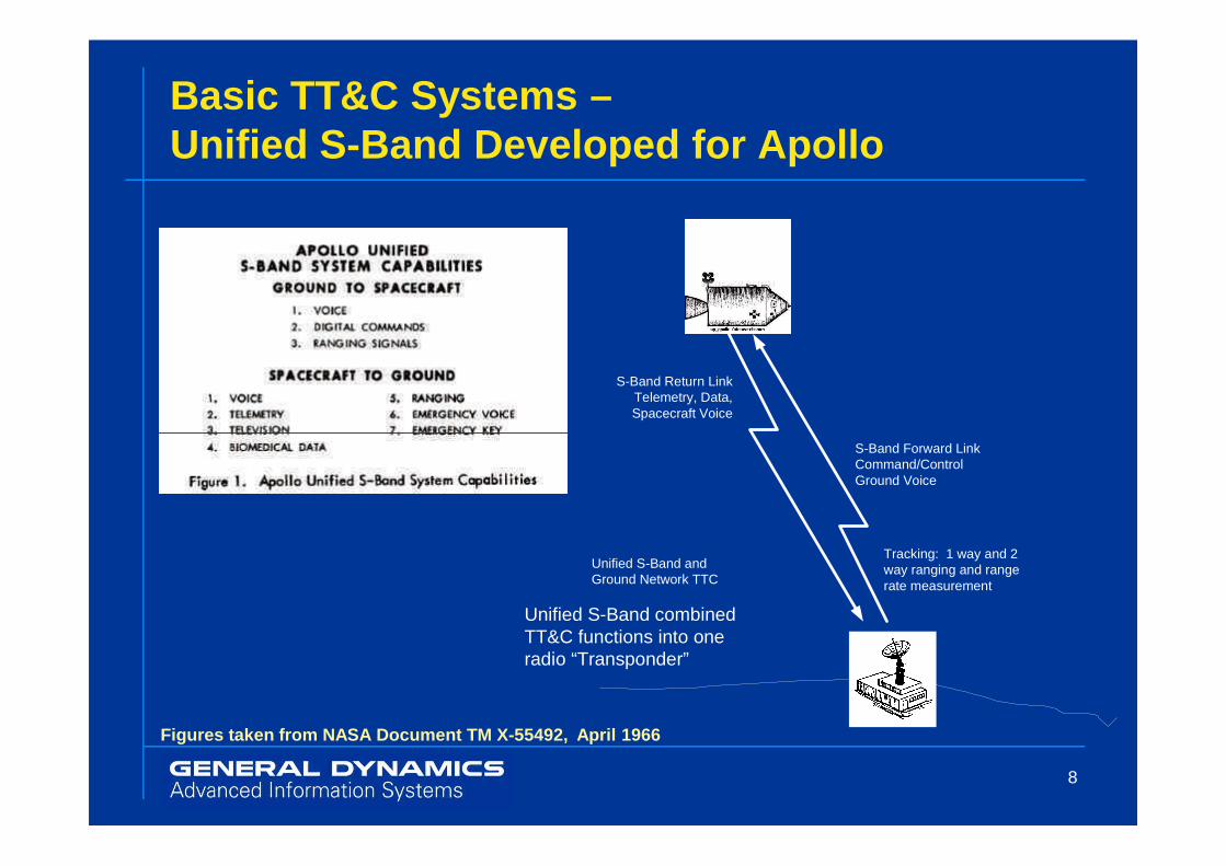
Basic TT&C Systems –Unified S -Band Developed for Apollo
S-Band Return Link Telemetry, Data,Spacecraft Voice
8
S-Band Forward Link Command/ControlGround Voice
Unified S-Band and Ground Network TTC
Tracking: 1 way and 2 way ranging and range rate measurement
Unified S-Band combined TT&C functions into one radio “Transponder”
Figures taken from NASA Document TM X-55492, April 1966

Basic TT&C Systems -Unified S -Band Transponder and Spectrum
9
Figures taken from NASA Document TM X-55492, April 1966
Basic TT&C --Tracking & Data Relay Satellite System � Limitations of Unified S-Band and Shuttle Development Drove
Need for Better TT&C capability� USB system required 11 ground stations for near-earth TT&C� Full orbital coverage not available� Limited user and data-rate capacity
� The Tracking and Data Relay Satellite System (TDRSS) system began development in the mid 1970’s
10
began development in the mid 1970’s� TDRSS design was based on ground station USB TTC system previously used
� TDRSS is a system of geosynchronous satellites implementing the TT&C functions� User satellites communicate with a TDRSS satellite using S-Band or Ku-Band
crosslinks with full orbital coverage� TDRSS satellite translates user signals to/from Ku-Band and link to TDRSS
ground stations.� Ranging and Range-rate tracking is accomplished relative to the TDRSS
satellite position.

TDRSS System Operation
� Services to White Sands Ground Terminal Shown� Guam Ground Terminal Operation is Similar
11Figure taken from NASA 450-SNUG

Basic TT&CTDRSS Communications� The TDRSS system uses direct sequence spread spectrum
� Leverages the need for PN-code ranging capability to include advantages of spread spectrum systems
� One of the first space applications of spread spectrum� ~3 Megachip direct sequence spreading
� Advantages of Spread Spectrum� Many users share the same frequency by assigning each a unique PN code.
This is known as “code division multiple access” (CDMA). Now utilized in cell
12
This is known as “code division multiple access” (CDMA). Now utilized in cell phones and wireless systems
� Transmitted power is spread over a wider portion of the frequency spectrum reducing interference to other users
� Interfering signals, including multi-path, are rejected as they are scrambled by the receiver’s PN code
� The PN code time delay is also used to measure the distance from the ground station to the satellite for tracking purposes.
� Multiple Access and numerous Frequency bands Provide high user communications capacity
Image courtesy NASA

Basic TT&CRanging and DS Spread Spectrum� Direct Sequence Spread Spectrum comes
virtually for free with PN Ranging capability
13
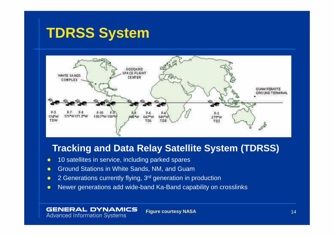
TDRSS System
14
Tracking and Data Relay Satellite System (TDRSS)� 10 satellites in service, including parked spares� Ground Stations in White Sands, NM, and Guam� 2 Generations currently flying, 3rd generation in production� Newer generations add wide-band Ka-Band capability on crosslinks
Figure courtesy NASA

U.S. Crewed Missions TTC & Comm.
� Project Mercury, Project Gemini� UHF/VHF main voice communications� UHF Command Receiver for commands and voice backup� C-Band Radar Transponder for tracking
� Apollo� Unified S-Band 2-way Radio Transponders for comm. and tracking
� Command Module (2) & Lunar Module
15
� Command Module (2) & Lunar Module
� Lunar Rover FM Voice/Command receiver� Command/Destruct receivers on booster stages 1,2,3
� Space Shuttle� Unified S-Band and TDRSS Transponder Capability (Not GD/Motorola)
� Space Station� Motorola/General Dynamics S-Band TDRSS/STDN Transponder

General Dynamics Scottsdale Heritage
� Originally Motorola’s Military/Government Electronics Group� Established in late 1940’s in Phoenix area� Expanded into Scottsdale facility in mid 1950s
� Space communications grew out of missile electronics developed in mid-1950s� Need emerges for vehicle Tracking, Telemetry, and Control by
ground stationsMotorola was a leading supplier of missile command/destruct
16
� Motorola was a leading supplier of missile command/destruct receivers
� Project Mercury begins in 1958� Motorola MCR-100 series UHF receiver used
for reliable backup communications� Flew on all Mercury missions� 10 channel Uplink commands plus voice backup
� Relay control outputs
� Mercury utilized worldwide radar tracking system
Figure taken from Motorola Datasheet
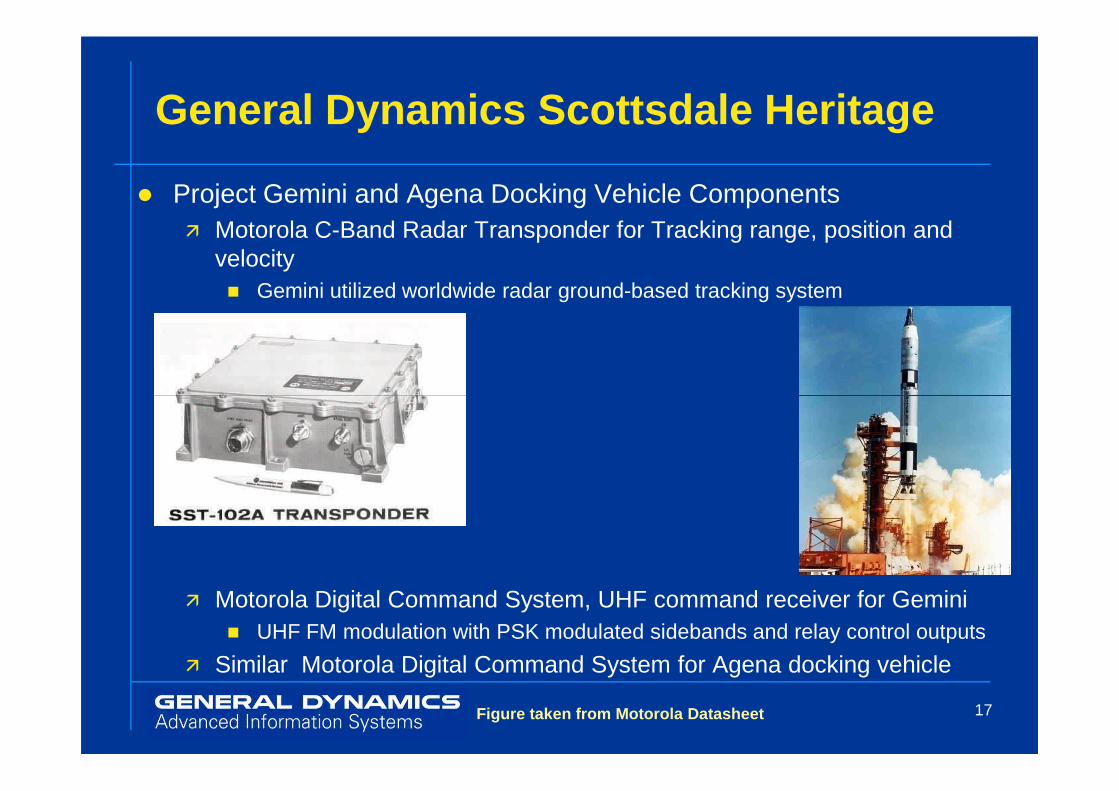
General Dynamics Scottsdale Heritage
� Project Gemini and Agena Docking Vehicle Components� Motorola C-Band Radar Transponder for Tracking range, position and
velocity� Gemini utilized worldwide radar ground-based tracking system
17
� Motorola Digital Command System, UHF command receiver for Gemini� UHF FM modulation with PSK modulated sidebands and relay control outputs
� Similar Motorola Digital Command System for Agena docking vehicle
Figure taken from Motorola Datasheet

General Dynamics Scottsdale Heritage
� Project Apollo Mission Components from Motorola/GD� Unified S-Band Transponder, Command Module (CM)� Unified S-Band Transponder, Lunar Module (LEM)� S-Band Communications transponder, 3rd Stage� Lunar Rover FM Command/Voice Receiver� Up-Data Link unit, (Data handling) Command Module� Flight Data/Command Destruct Receivers Stages 1,2,3
18
� Flight Data/Command Destruct Receivers Stages 1,2,3� S-Band Command Receiver, ALSEP Experiment
Images courtesy NASA and General Dynamics
General Dynamics Scottsdale Heritage
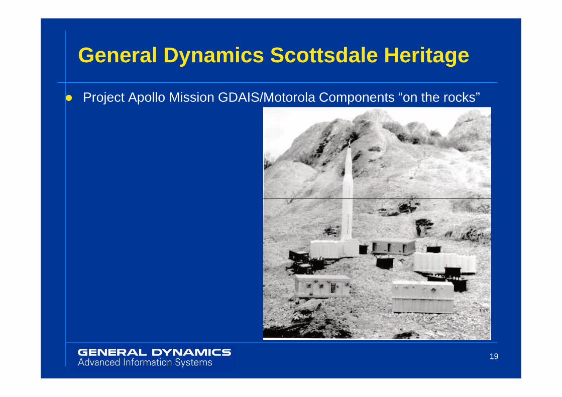
� Project Apollo Mission GDAIS/Motorola Components “on the rocks”
19
General Dynamics Scottsdale Heritage
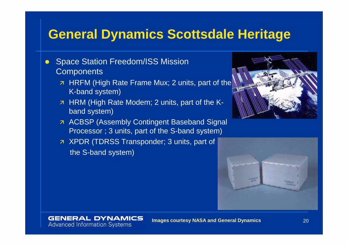
� Space Station Freedom/ISS Mission Components� HRFM (High Rate Frame Mux; 2 units, part of the
K-band system)� HRM (High Rate Modem; 2 units, part of the K-
band system)� ACBSP (Assembly Contingent Baseband Signal
20
� ACBSP (Assembly Contingent Baseband Signal Processor ; 3 units, part of the S-band system)
� XPDR (TDRSS Transponder; 3 units, part of the S-band system)
Images courtesy NASA and General Dynamics
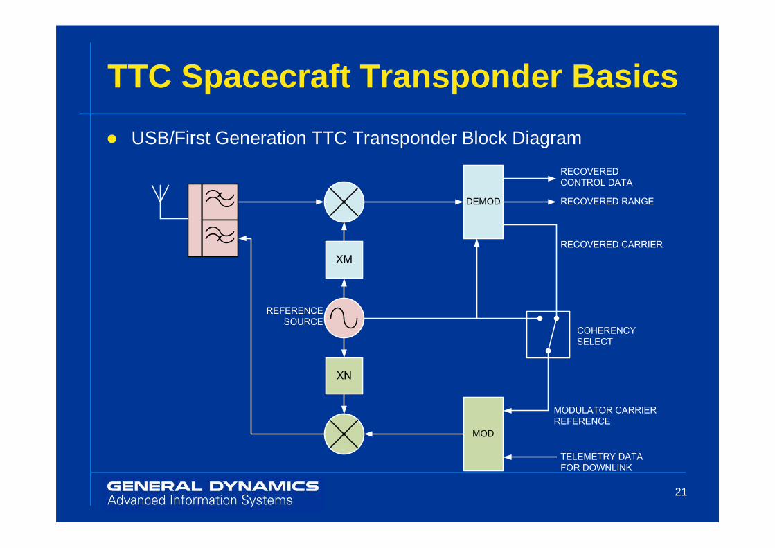
TTC Spacecraft Transponder Basics
XM
DEMOD
RECOVERED
CONTROL DATA
RECOVERED RANGE
RECOVERED CARRIER
� USB/First Generation TTC Transponder Block Diagram
21
XN
MOD
COHERENCY
SELECT
TELEMETRY DATA
FOR DOWNLINK
REFERENCE
SOURCE
MODULATOR CARRIER
REFERENCE

TTC Spacecraft Transponder Basics
� TDRSS Spread Spectrum TTC Transponder Simplified Block Diagram
22

Next Generation USHuman Space Flight Program
� In 2004, President Bush challenged NASA to send the U.S. back to the Moon and Mars� Kicked off ambitious Constellation Program to redefine the U.S.
human space flight program� Replaces the aging Space Shuttle system including following segments:� Ares Heavy Lift Booster development,
Orion Crew Exploration Vehicle (CEV)
23
� Orion Crew Exploration Vehicle (CEV)� Altair Lunar Excursion vehicles
Images Courtesy NASA

Ongoing Changes to U.S. Human Space Flight Program
� Obama Administration in 2010 Directed Changes to NASA’s Human Space Flight Program Objectives� Constellation and Orion Programs Cancelled � Lengthened schedule for return to the Moon, focuses on Shuttle
replacement in near term� Increased Private Sector Involvement to develop space vehicles
� 2010 NASA Authorization Act Redirects NASA goals:
24
� 2010 NASA Authorization Act Redirects NASA goals:� Continue development of Multi-Purpose Crew Vehicle (MPCV) and Space
Launch System to enable crewed missions beyond low Earth orbit by 2016� MPCV based on Orion CEV baseline
� Evolutionary approach and architecture supports changing objectives and timeframes
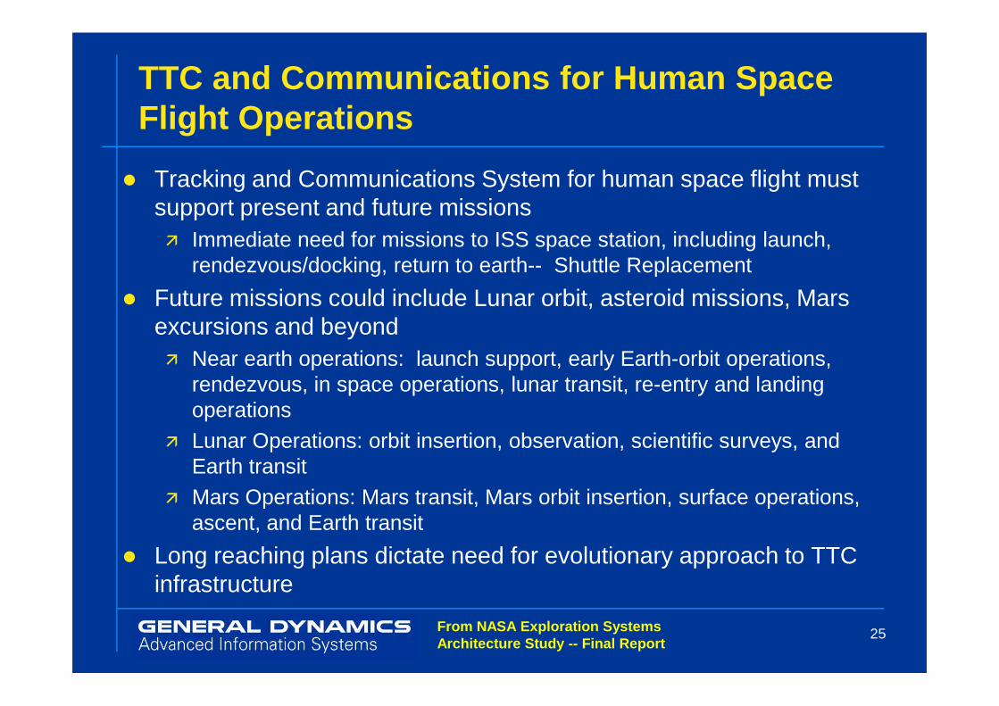
TTC and Communications for Human Space Flight Operations
� Tracking and Communications System for human space flight must support present and future missions� Immediate need for missions to ISS space station, including launch,
rendezvous/docking, return to earth-- Shuttle Replacement
� Future missions could include Lunar orbit, asteroid missions, Mars excursions and beyond� Near earth operations: launch support, early Earth-orbit operations,
25
� Near earth operations: launch support, early Earth-orbit operations, rendezvous, in space operations, lunar transit, re-entry and landing operations
� Lunar Operations: orbit insertion, observation, scientific surveys, and Earth transit
� Mars Operations: Mars transit, Mars orbit insertion, surface operations, ascent, and Earth transit
� Long reaching plans dictate need for evolutionary approach to TTC infrastructure
From NASA Exploration Systems Architecture Study -- Final Report

TTC and Communications for MPCV
� TTC requirements for the Multi-Purpose Crew Vehicle (MPCV) focus on immediate needs with long range mission requirements in mind� Near Earth needs will be satisfied by the existing Space Network Tracking
and Data Relay Satellite System (TDRSS) constellation through 2025� Planned TDRSS upgrade deployment occurs in the 2015 time frame
� Space-to-space TDRSS TTC allows docking and communications directly between MPCV and ISS or MPCV and Moon missions.
26
between MPCV and ISS or MPCV and Moon missions.� Requires dual-mode transponder capable of operation in a space-based user
transponder mode or operation in Earth station mode.� Capabilities include space-borne ranging and range-rate measurement
� Similar to Apollo, initial lunar sortie missions will be supported by Earth ground stations, primarily the Deep Space Network (DSN)� DSN upgrades planned for TDRSS compatible receivers supporting MPCV
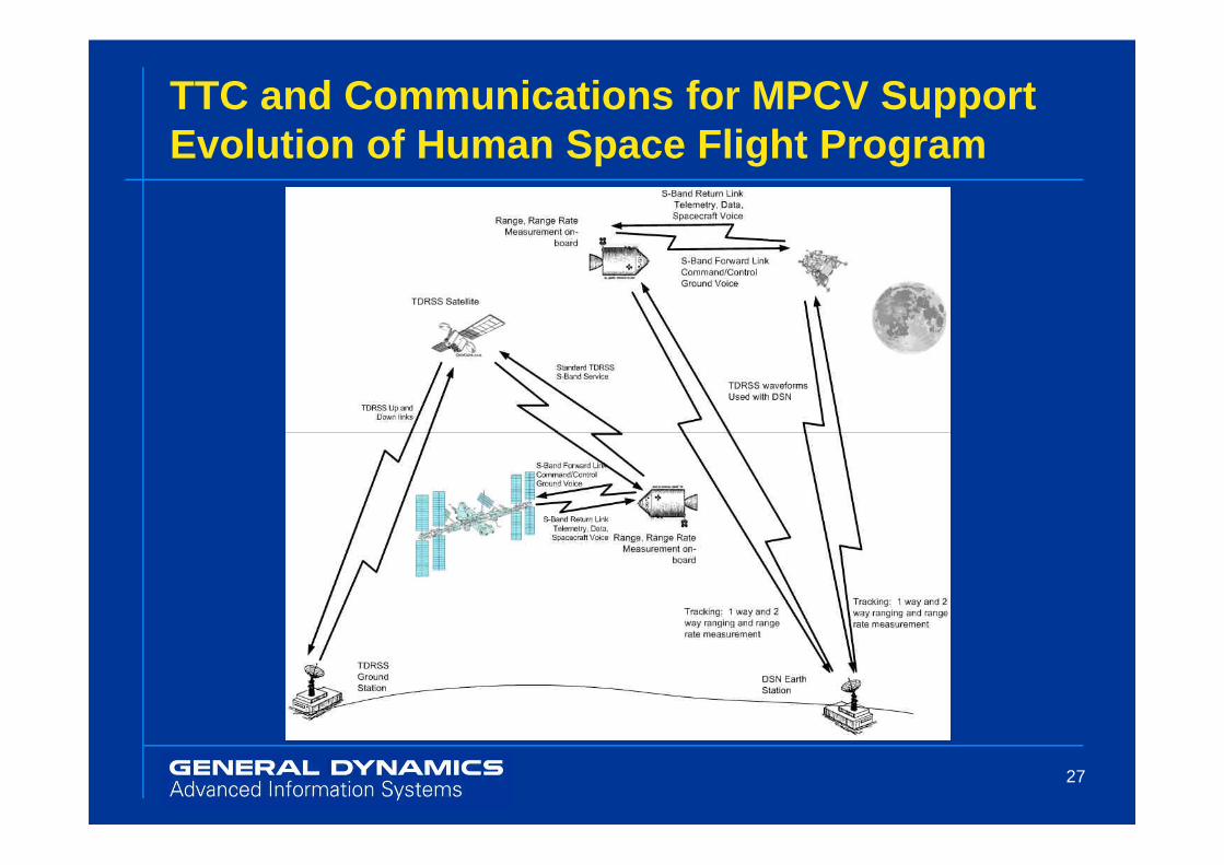
TTC and Communications for MPCV Support Evolution of Human Space Flight Program
27
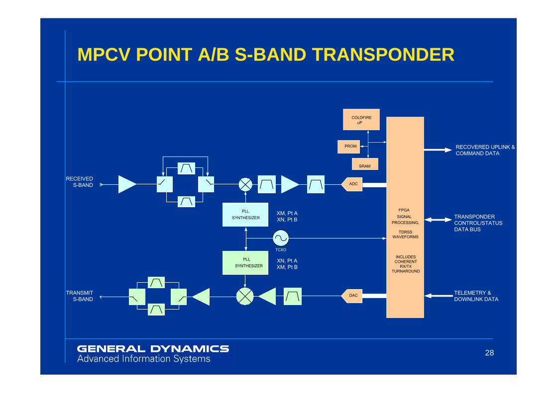
MPCV POINT A/B S-BAND TRANSPONDER
ADC
COLDFIRE
uP
SRAM
PROM
RECEIVED
S-BAND
RECOVERED UPLINK &
COMMAND DATA
28
PLL
SYNTHESIZER
80
TCXO
PLL
SYNTHESIZER
XM, Pt A
XN, Pt B
XN, Pt A
XM, Pt B
DAC
FPGA
SIGNAL
PROCESSING,
TDRSS
WAVEFORMS
TRANSPONDER
CONTROL/STATUS
DATA BUS
TELEMETRY &
DOWNLINK DATA
INCLUDES
COHERENT
RX/TX
TURNAROUND
TRANSMIT
S-BAND

MPCV S-BAND TRANSPONDER OVERVIEW
� Functional Overview� TDRSS Waveform Compatible � Point A (User Transponder) or
Point B (Ground Station Mode) Operation� Operation on 3 TDRSS frequency bands
Capable of majority of TDRSS waveforms on command
29
� Capable of majority of TDRSS waveforms on command� Coherent or non-coherent operation� Waveforms instantiated in Software and FPGA Gateware� Radiation hardened and ruggedized for operation during launch� New bandwidth efficient modulation waveforms (non-spread)
� better spectrum utilization and higher bit rates� Root-Raised Cosine pulse shaping

MPCV S-BAND TRANSPONDER OVERVIEW
� Physical Characteristics� Mass: 10 lbs� DC Power:19 W, Tx & Rx
8.00” Max
30
7.00” Max
6.00” Max

MPCV S-Band Transponder is STRS Compatible
� Our MPCV Transponder utilizes NASA’s Space Telecommunications Radio System (STRS) Software Defined Radio (SDR) architecture� Developed for CONNECT program� High level operating system provides standardized open-architecture
approach� STRS Outer Layer provides seamless interface to detailed waveform
31
� STRS Outer Layer provides seamless interface to detailed waveform and hardware functions
� SDR Minimizes need for costly hardware changes
� Allows use of STRS Repository� Collection of hardware and software modules, definitions, documents
for mission reuse � Allows for 3rd Party developers to easily update radio function
� Result is increased capability for evolution with changes in human space program objectives.

SDR/STRS Conceptual Diagram
text
General Processing Module (GPM)
General Purpose Processor
Host/TT&C
Interface
Ground Test
Interface
Low Speed
Signal
Processing
Persistent Memory
Radio
Configuration
& System
ControlWork Area Memory
Operating
Environment
Waveform /
Application
32
texttext
Data
Formatting
Spacecraft
Data
Interface
Clock
Distribution
Transmit RFDigital to
Analog
RF Module (RFM)
High Speed
Digital Signal
Processing
Signal Processing Module (SPM)
Antenna
Interface
Clock
Interface
Analog to
DigitalReceive RF
Antenna
Control
Interface
System
Control
Variable
Gain/
FrequencyTest &
Status
Test &
Status
Data
Buffer/
Storage
Waveform

STRS Software Architecture
33
Summary and Conclusions
� General Dynamics AIS Scottsdale has a long heritage supporting the U.S. Human Space Flight Program� We are pleased to support NASA and the world in continuing
human exploration of space
� Our MPCV S-Band Transponder Supports NASA’s need for an Evolutionary TTC System
34
need for an Evolutionary TTC System � Supports near term needs but provides flexibility for the future� Flexibility provided by Software Programmable architecture� Capability of operation in TDRSS Point A or Point B Modes
� STRS SDR Provides for easy update of the MPCV transponder function to meet the needs of the future of Human Space Flight

36
Q&A
All images and charts in this presentation are the property of General Dynamics unless otherwise specified
Motorola’s Government Electronics Group was acquire d by General Dynamics in 2001