radio frequency series - b & b · pdf fileradio frequency series ... optimum setting on...
TRANSCRIPT
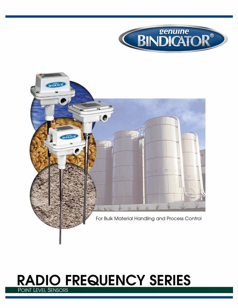
RADIO FREQUENCY SERIESPOINT LEVEL SENSORS
For Bulk Material Handling and Process Control
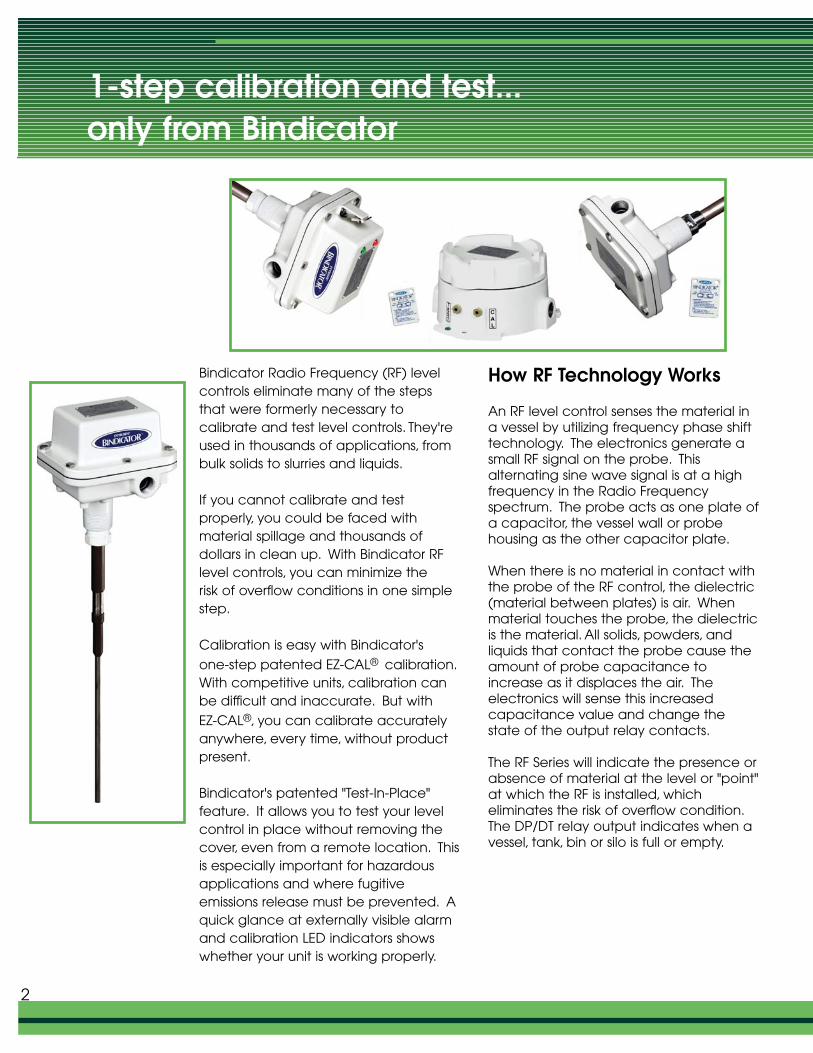
Bindicator Radio Frequency (RF) levelcontrols eliminate many of the stepsthat were formerly necessary to calibrate and test level controls. They'reused in thousands of applications, frombulk solids to slurries and liquids.
If you cannot calibrate and test properly, you could be faced withmaterial spillage and thousands of dollars in clean up. With Bindicator RFlevel controls, you can minimize the risk of overflow conditions in one simplestep.
Calibration is easy with Bindicator's
one-step patented EZ-CAL® calibration.With competitive units, calibration canbe difficult and inaccurate. But with
EZ-CAL®, you can calibrate accuratelyanywhere, every time, without productpresent.
Bindicator's patented "Test-In-Place"feature. It allows you to test your levelcontrol in place without removing thecover, even from a remote location. Thisis especially important for hazardousapplications and where fugitive emissions release must be prevented. Aquick glance at externally visible alarmand calibration LED indicators showswhether your unit is working properly.
How RF Technology Works
An RF level control senses the material ina vessel by utilizing frequency phase shifttechnology. The electronics generate asmall RF signal on the probe. This alternating sine wave signal is at a highfrequency in the Radio Frequency spectrum. The probe acts as one plate ofa capacitor, the vessel wall or probehousing as the other capacitor plate.
When there is no material in contact withthe probe of the RF control, the dielectric(material between plates) is air. Whenmaterial touches the probe, the dielectricis the material. All solids, powders, andliquids that contact the probe cause theamount of probe capacitance toincrease as it displaces the air. The electronics will sense this increasedcapacitance value and change thestate of the output relay contacts.
The RF Series will indicate the presence orabsence of material at the level or "point"at which the RF is installed, which eliminates the risk of overflow condition.The DP/DT relay output indicates when avessel, tank, bin or silo is full or empty.
1-step calibration and test...only from Bindicator
2
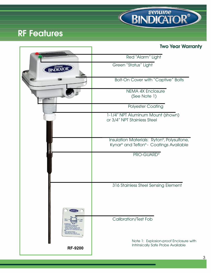
RF FeaturesTwo Year Warranty
Red “Alarm” Light
Green “Status” Light
Bolt-On Cover with “Captive” Bolts
NEMA 4X Enclosure(See Note 1)
1-1/4” NPT Aluminum Mount (shown)or 3/4” NPT Stainless Steel
Polyester Coating
Insulation Materials: Ryton®, Polysulfone,Kynar® and Teflon® - Coatings Available
PRO-GUARD®
316 Stainless Steel Sensing Element
Calibration/Test Fob
3
Note 1: Explosion-proof Enclosure withIntrinsically Safe Probe Available
RF-9200
A Wide Array of Features and Benefits
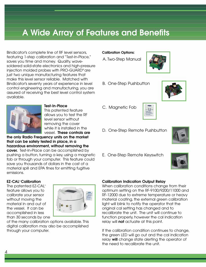
Bindicator's complete line of RF level sensors,featuring 1-step calibration and “Test-In-Place,”saves you time and money. Quality, wave-soldered solid-state electronics and high-pressureinjection molded probes with PRO-GUARD® arejust two unique manufacturing features thatmake this level sensor reliable. Matched withBindicator's seventy years of experience in levelcontrol engineering and manufacturing, you areassured of receiving the best level control system available.
Test-In-PlaceThis patented featureallows you to test the RFlevel sensor without removing the coverwhile it is installed in the vessel. These controls are
the only Radio Frequency units on the marketthat can be safely tested in place, in a hazardous environment, without removing thecover. Test-In-Place can be accomplished bypushing a button, turning a key, using a magneticfob or through your computer. This feature couldsave you thousands of dollars in the cost of amaterial spill and EPA fines for emitting fugitiveemissions.
EZ-CAL® CalibrationThe patented EZ-CAL®
feature allows you to calibrate your sensorwithout moving thematerial in and out ofthe vessel. It can beaccomplished in lessthan 30 seconds by oneof the many calibration options available. Thisdigital calibration may also be accomplishedthrough your computer.
Calibration Options:
Calibration Indication Output RelayWhen calibration conditions change from theiroptimum setting on the RF-9100/9200/11000 andRF-12000 due to extreme temperature or heavymaterial coating, the external green calibrationlight will blink to notify the operator that the original cal setting has changed and to recalibrate the unit. The unit will continue tofunction properly, however the cal indicationrelay will not actuate at this point.
If the calibration condition continues to change,the green LED will go out and the cal indicationrelay will change state alerting the operator ofthe need to recalibrate the unit.
A. Two-Step Manual
B. One-Step Pushbutton
C. Magnetic Fob
D. One-Step Remote Pushbutton
E. One-Step Remote Keyswitch
4
PRO-GUARD®
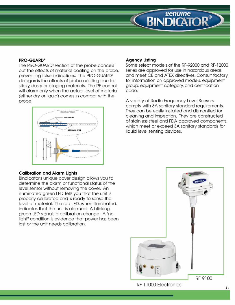
The PRO-GUARD® section of the probe cancelsout the effects of material coating on the probe,preventing false indications. The PRO-GUARD®
disregards the effects of probe coating due tosticky, dusty or clinging materials. The RF controlwill alarm only when the actual level of material(either dry or liquid) comes in contact with theprobe.
Calibration and Alarm LightsBindicator's unique cover design allows you todetermine the alarm or functional status of thelevel sensor without removing the cover. An illuminated green LED tells you that the unit isproperly calibrated and is ready to sense thelevel of material. The red LED, when illuminated,indicates that the unit is alarmed. A blinkinggreen LED signals a calibration change. A "no-light" condition is evidence that power has beenlost or the unit needs calibration.
Agency ListingSome select models of the RF-92000 and RF-12000series are approved for use in hazardous areasand meet CE and ATEX directives. Consult factoryfor information on approved models, equipmentgroup, equipment category, and certificationcode.
A variety of Radio Frequency Level Sensors comply with 3A sanitary standard requirements.They can be easily installed and dismantled forcleaning and inspection. They are constructed of stainless steel and FDA approved components,which meet or exceed 3A sanitary standards forliquid level sensing devices.
5RF 11000 Electronics
RF 9100
Probe Selection
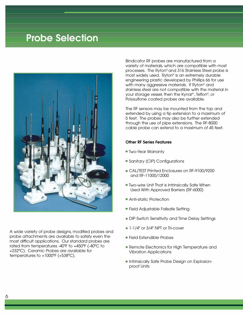
A wide variety of probe designs, modified probes andprobe attachments are available to satisfy even themost difficult applications. Our standard probes arerated from temperatures -40ºF to +450ºF (-40ºC to+232ºC). Ceramic Probes are available for temperatures to +1000ºF (+538ºC).
Bindicator RF probes are manufactured from a variety of materials, which are compatible with mostprocesses. The Ryton® and 316 Stainless Steel probe ismost widely used. Ryton® is an extremely durableengineering plastic developed by Phillips 66 for usewith many aggressive materials. If Ryton® andstainless steel are not compatible with the material inyour storage vessel, then the Kynar® , Teflon®, orPolysulfone coated probes are available.
The RF sensors may be mounted from the top andextended by using a tip extension to a maximum of5 feet. The probes may also be further extendedthrough the use of pipe extensions. The RF-8000cable probe can extend to a maximum of 45 feet.
Other RF Series Features
Two-Year Warranty
Sanitary (CIP) Configurations
CAL/TEST Printed Enclosures on RF-9100/9200and RF-11000/12000
Two-wire Unit That is Intrinsically Safe When Used With Approved Barriers (RF-6000)
Anti-static Protection
Field Adjustable Failsafe Setting
DIP Switch Sensitivity and Time Delay Settings
1-1/4" or 3/4" NPT or Tri-cover
Field Extendible Probes
Remote Electronics for High Temperature andVibration Applications
Intrinsically Safe Probe Design on Explosion-proof Units
6
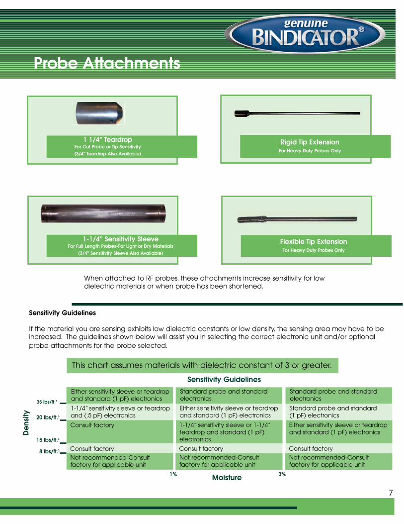
Probe Attachments
When attached to RF probes, these attachments increase sensitivity for lowdielectric materials or when probe has been shortened.
Sensitivity Guidelines
If the material you are sensing exhibits low dielectric constants or low density, the sensing area may have to beincreased. The guidelines shown below will assist you in selecting the correct electronic unit and/or optionalprobe attachments for the probe selected.
7
Standard probe and standardelectronics
Either sensitivity sleeve or teardropand standard (1 pF) electronics
1-1/4” sensitivity sleeve or 1-1/4”teardrop and standard (1 pF)electronics
Consult factory
Not recommended-Consult factory for applicable unit
Either sensitivity sleeve or teardropand standard (1 pF) electronics
1-1/4” sensitivity sleeve or teardropand (.5 pF) electronics
Consult factory
Consult factory
Not recommended-Consult factory for applicable unit
Standard probe and standardelectronics
Standard probe and standard(1 pF) electronics
Either sensitivity sleeve or teardropand standard (1 pF) electronics
Consult factory
Not recommended-Consult factory for applicable unit
Sensitivity Guidelines
This chart assumes materials with dielectric constant of 3 or greater.
De
nsity
Moisture1% 3%
35 lbs/ft.3
20 lbs/ft.3
15 lbs/ft.3
8 lbs/ft.3
1-1/4” Sensitivity Sleeve For Full Length Probes-For Light or Dry Materials
(3/4” Sensitivity Sleeve Also Available)
1 1/4” TeardropFor Cut Probe or Tip Sensitivity(3/4” Teardrop Also Available)
Flexible Tip ExtensionFor Heavy Duty Probes Only
Rigid Tip ExtensionFor Heavy Duty Probes Only
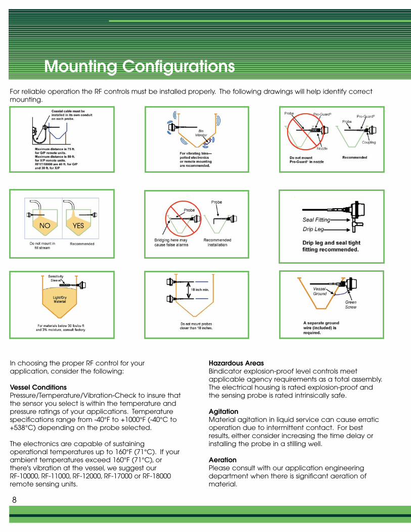
Mounting ConfigurationsFor reliable operation the RF controls must be installed properly. The following drawings will help identify correctmounting.
In choosing the proper RF control for your application, consider the following:
Vessel ConditionsPressure/Temperature/Vibration-Check to insure thatthe sensor you select is within the temperature andpressure ratings of your applications. Temperaturespecifications range from -40°F to +1000°F (-40°C to+538°C) depending on the probe selected.
The electronics are capable of sustaining operational temperatures up to 160°F (71°C). If yourambient temperatures exceed 160°F (71°C), orthere's vibration at the vessel, we suggest our RF-10000, RF-11000, RF-12000, RF-17000 or RF-18000remote sensing units.
Hazardous AreasBindicator explosion-proof level controls meet applicable agency requirements as a total assembly.The electrical housing is rated explosion-proof andthe sensing probe is rated intrinsically safe.
AgitationMaterial agitation in liquid service can cause erraticoperation due to intermittent contact. For bestresults, either consider increasing the time delay orinstalling the probe in a stilling well.
AerationPlease consult with our application engineeringdepartment when there is significant aeration ofmaterial.
8
v
v
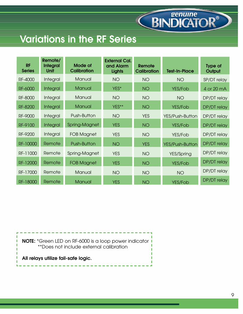
Variations in the RF Series
NOTE: *Green LED on RF-6000 is a loop power indicator**Does not include external calibration
All relays utilize fail-safe logic.
9
RFSeries
Remote/Integral
UnitMode of
Calibration
External Cal.and Alarm
LightsRemote
Calibration Test-In-PlaceType of Output
RF-4000
RF-6000
RF-8000
RF-8200
RF-9000
RF-9100
RF-9200
RF-10000
RF-11000
RF-12000
RF-17000
RF-18000
Integral
Integral
Integral
Integral
Integral
Integral
Integral
Remote
Remote
Remote
Remote
Remote
Manual
Manual
Manual
Manual
Push-Button
Spring-Magnet
FOB Magnet
Push-Button
Spring-Magnet
FOB Magnet
Manual
Manual
NO
YES*
NO
YES**
NO
YES
YES
NO
YES
YES
NO
YES
NO
YES/Fob
NO
YES/Fob
YES/Push-Button
YES/Fob
YES/Fob
YES/Push-Button
YES/Spring
YES/Fob
NO
YES/Fob
NO
NO
NO
NO
YES
NO
NO
YES
NO
NO
NO
NO
SP/DT relay
4 or 20 mA
DP/DT relay
DP/DT relay
DP/DT relay
DP/DT relay
DP/DT relay
DP/DT relay
DP/DT relay
DP/DT relay
DP/DT relay
DP/DT relay
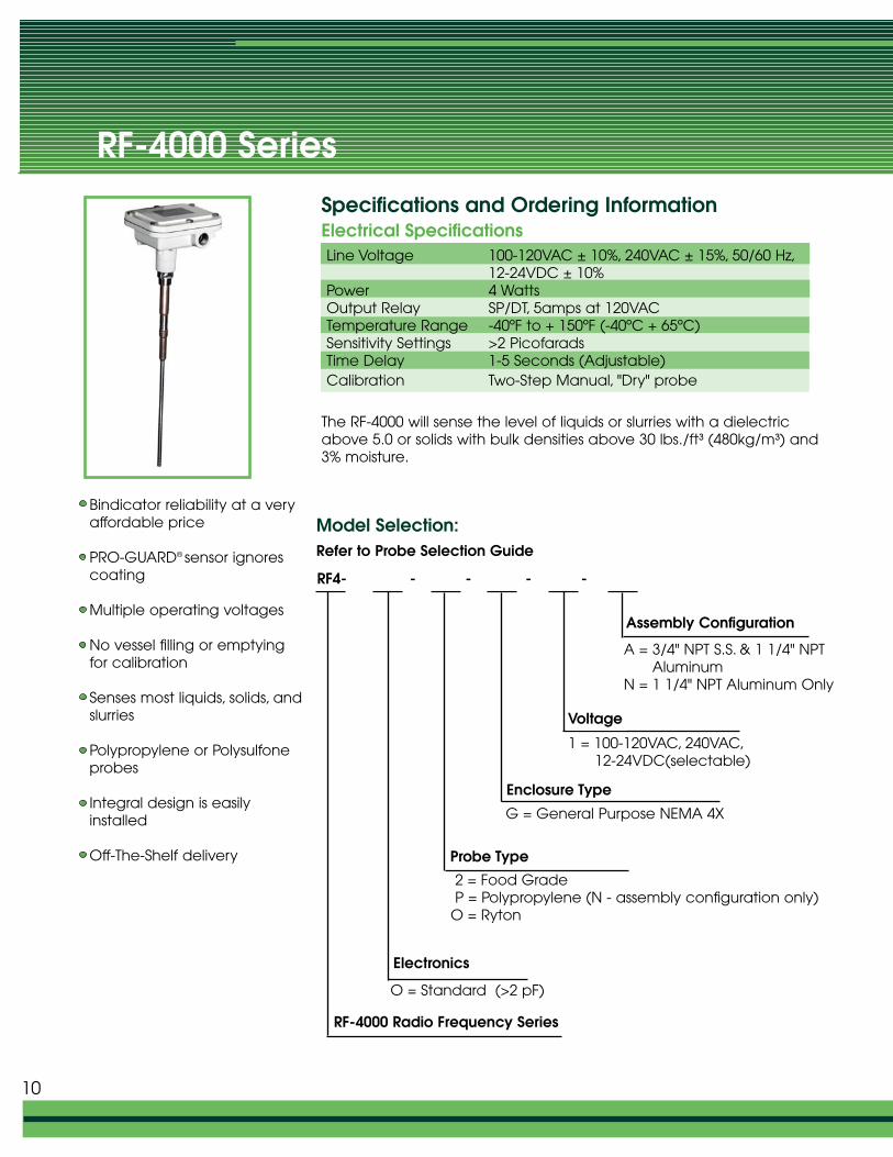
RF-4000 Series
Line Voltage 100-120VAC ± 10%, 240VAC ± 15%, 50/60 Hz,12-24VDC ± 10%
Power 4 WattsOutput Relay SP/DT, 5amps at 120VACTemperature Range -40ºF to + 150ºF (-40ºC + 65ºC)Sensitivity Settings >2 PicofaradsTime Delay 1-5 Seconds (Adjustable)Calibration Two-Step Manual, "Dry" probe
Bindicator reliability at a veryaffordable price
PRO-GUARD® sensor ignorescoating
Multiple operating voltages
No vessel filling or emptyingfor calibration
Senses most liquids, solids, andslurries
Polypropylene or Polysulfoneprobes
Integral design is easilyinstalled
Off-The-Shelf delivery
The RF-4000 will sense the level of liquids or slurries with a dielectricabove 5.0 or solids with bulk densities above 30 lbs./ft³ (480kg/m³) and3% moisture.
Assembly Configuration
A = 3/4" NPT S.S. & 1 1/4" NPTAluminum
N = 1 1/4" NPT Aluminum Only
Voltage
1 = 100-120VAC, 240VAC,12-24VDC(selectable)
Enclosure Type
G = General Purpose NEMA 4X
2 = Food Grade P = Polypropylene (N - assembly configuration only)
O = Ryton
Probe Type
Electronics
O = Standard (>2 pF)
RF-4000 Radio Frequency Series
RF4- - - - -
Specifications and Ordering InformationElectrical Specifications
Model Selection:Refer to Probe Selection Guide
10
A = 3/4" S.S. & 1 1/4" Aluminum & Flush MountS = Sanitary Fitting 1” or 1 1/2” tri-clamp
size (See Note 1)N = 1 1/4" Alum. Only (NEMA 4X ONLY)
(Consult factory for agency listing)H = 3/4" Hastelloy C (for Teflon® probes only)
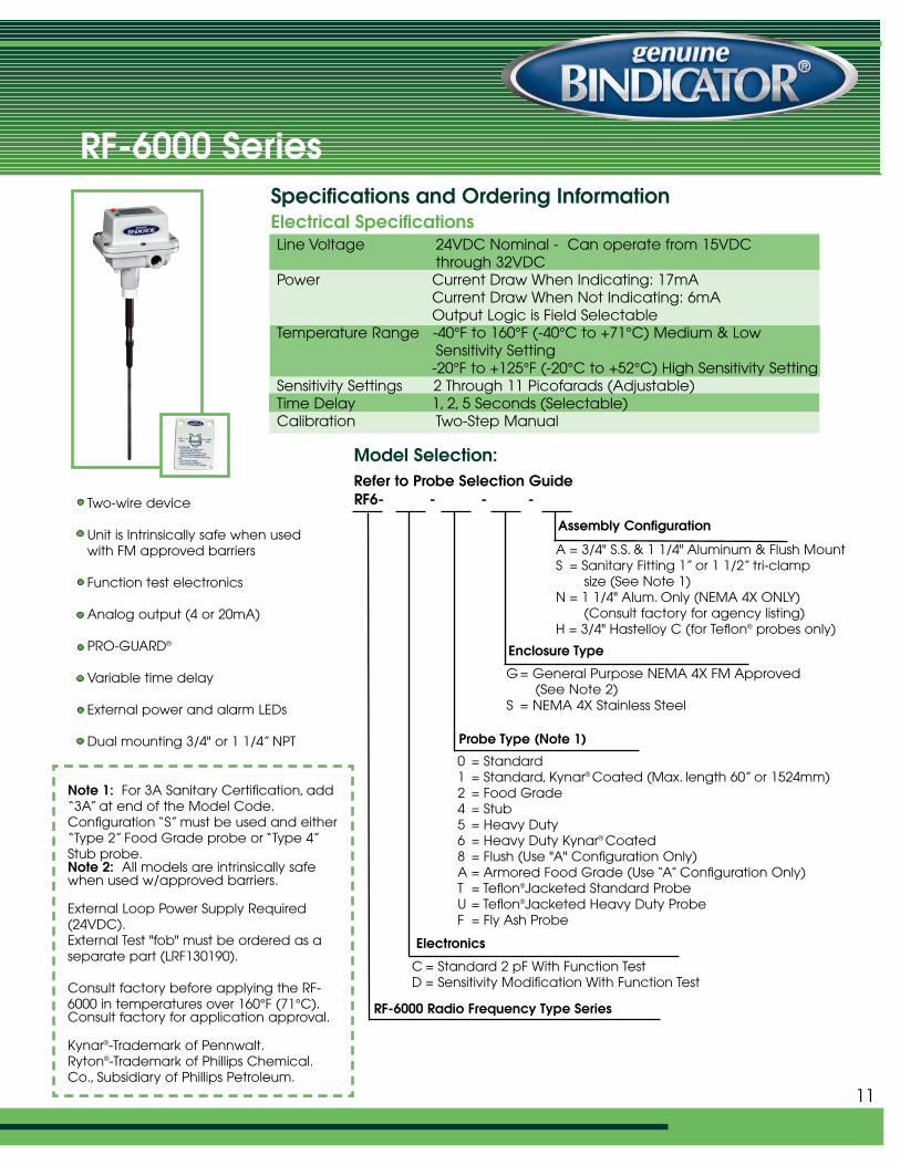
RF-6000 Series
Line Voltage 24VDC Nominal - Can operate from 15VDC through 32VDC
Power Current Draw When Indicating: 17mACurrent Draw When Not Indicating: 6mAOutput Logic is Field Selectable
Temperature Range -40°F to 160°F (-40°C to +71°C) Medium & Low Sensitivity Setting-20°F to +125°F (-20°C to +52°C) High Sensitivity Setting
Sensitivity Settings 2 Through 11 Picofarads (Adjustable)Time Delay 1, 2, 5 Seconds (Selectable)Calibration Two-Step Manual
Two-wire device
Unit is Intrinsically safe when usedwith FM approved barriers
Function test electronics
Analog output (4 or 20mA)
PRO-GUARD®
Variable time delay
External power and alarm LEDs
Dual mounting 3/4" or 1 1/4” NPT
Assembly Configuration
G = General Purpose NEMA 4X FM Approved (See Note 2)
S = NEMA 4X Stainless Steel
0 = Standard1 = Standard, Kynar® Coated (Max. length 60” or 1524mm)2 = Food Grade4 = Stub5 = Heavy Duty6 = Heavy Duty Kynar® Coated8 = Flush (Use "A" Configuration Only)A = Armored Food Grade (Use “A” Configuration Only)T = Teflon®Jacketed Standard ProbeU = Teflon®Jacketed Heavy Duty ProbeF = Fly Ash Probe
Probe Type (Note 1)
Electronics
C = Standard 2 pF With Function TestD = Sensitivity Modification With Function Test
RF-6000 Radio Frequency Type Series
RF6- - - -
Specifications and Ordering InformationElectrical Specifications
Model Selection:Refer to Probe Selection Guide
Enclosure Type
Note 1: For 3A Sanitary Certification, add“3A” at end of the Model Code.Configuration “S” must be used and either“Type 2” Food Grade probe or “Type 4”Stub probe.Note 2: All models are intrinsically safewhen used w/approved barriers.
External Loop Power Supply Required (24VDC).External Test "fob" must be ordered as a separate part (LRF130190).
Consult factory before applying the RF-6000 in temperatures over 160°F (71°C).Consult factory for application approval.
Kynar®-Trademark of Pennwalt.Ryton®-Trademark of Phillips Chemical.Co., Subsidiary of Phillips Petroleum.
11
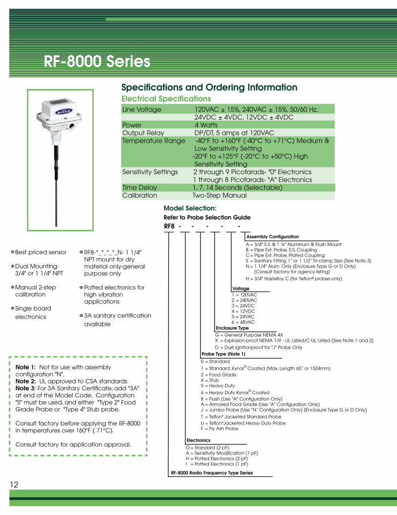
RF-8000 Series
Line Voltage 120VAC ± 15%, 240VAC ± 15%, 50/60 Hz,24VDC ± 4VDC, 12VDC ± 4VDC
Power 4 WattsOutput Relay DP/DT, 5 amps at 120VACTemperature Range -40°F to +160°F (-40°C to +71°C) Medium &
Low Sensitivity Setting-20°F to +125°F (-20°C to +50°C) High Sensitivity Setting
Sensitivity Settings 2 through 9 Picofarads- "0" Electronics1 through 8 Picofarads- "A" Electronics
Time Delay 1, 7, 14 Seconds (Selectable)Calibration Two-Step Manual
Assembly Configuration
Voltage1 = 120VAC2 = 240VAC3 = 24VDC4 = 12VDC5 = 24VAC6 = 48VAC
Enclosure TypeG = General Purpose NEMA 4XX = Explosion-proof NEMA 7/9 - UL Listed/C-UL Listed (See Note 1 and 2)
D = Dust Ignitionproof for "J" Probe OnlyProbe Type (Note 1)
RF8 - - - - -
Specifications and Ordering InformationElectrical Specifications
Model Selection:Refer to Probe Selection Guide
Electronics
O = Standard (2 pF)A = Sensitivity Modification (1 pF)H = Potted Electronics (2 pF)I = Potted Electronics (1 pF)
RF-8000 Radio Frequency Type Series
Best priced sensor
Dual Mounting-3/4" or 1 1/4" NPT
Manual 2-step calibration
Single board electronics
RF8-*_*_*_*_N- 1 1/4"NPT mount for drymaterial only-generalpurpose only
Potted electronics forhigh vibration applications
3A sanitary certificationavailable
Note 1: Not for use with assembly configuration "N".Note 2: UL approved to CSA standards.Note 3: For 3A Sanitary Certificate, add "3A"at end of the Model Code. Configuration"S" must be used, and either "Type 2" FoodGrade Probe or "Type 4" Stub probe.
Consult factory before applying the RF-8000in temperatures over 160°F ( 71°C).
Consult factory for application approval.
12
A = 3/4" S.S. & 1 ¼" Aluminum & Flush MountB = Pipe Ext. Probe, S.S. CouplingC = Pipe Ext. Probe, Plated CouplingS = Sanitary Fitting 1” or 1 1/2” Tri-clamp Size (See Note 3)N = 1 1/4" Alum. Only (Enclosure Type G or D Only)
(Consult factory for agency listing)
H = 3/4" Hastelloy C (for Teflon® probes only)
0 = Standard
1 = Standard, Kynar® Coated (Max. Length 60” or 1524mm)2 = Food Grade4 = Stub5 = Heavy Duty
6 = Heavy Duty Kynar® Coated8 = Flush (Use "A" Configuration Only)A = Armored Food Grade (Use “A” Configuration Only)J = Jumbo Probe (Use “N” Configuration Only) (Enclosure Type G or D Only)
T = Teflon® Jacketed Standard ProbeU = Teflon®Jacketed Heavy Duty ProbeF = Fly Ash Probe
Cable Probe Material
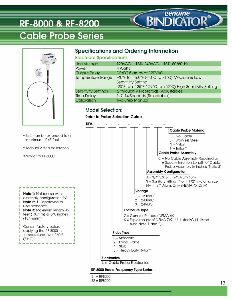
RF-8000 & RF-8200Cable Probe Series
Line Voltage 120VAC ± 15%, 240VAC ± 15%, 50/60, HzPower 4 WattsOutput Relay DP/DT, 5 amps at 120VACTemperature Range -40°F to +160°F (-40°C to 71°C) Medium & Low
Sensitivity Setting-20°F to + 125°F (-29°C to +52°C) High Sensitivity Setting
Sensitivity Settings 2 through 9 Picofarads (Adjustable)Time Delay 1, 7, 14 Seconds (Selectable)Calibration Two-Step Manual
Unit can be extended to amaximum of 45 feet
Manual 2-step calibration
Similar to RF-8000
RF8- - - - - - -
Specifications and Ordering InformationElectrical Specifications
Model Selection:Refer to Probe Selection Guide
Note 1: Not for use withassembly configuration "N".Note 2: UL approved toCSA standards.Note 3: Maximum length 45feet (13.71m) or 540 inches(13716mm).
Consult factory beforeapplying the RF-8000 in temperatures over 160°F(71°C).
Assembly Configuration
A= 3/4" S.S. & 1 1/4" AluminumS = Sanitary Fitting 1” or 1 1/2” tri-clamp sizeN= 1 1/4" Alum. Only (NEMA 4X Only)
Voltage1 = 120VAC2 = 240VAC3 = 24VDC
Enclosure Type
G= General Purpose NEMA 4XX = Explosion-proof NEMA 7/9 - UL Listed/C-UL Listed
(See Note 1 and 2)
0 = Standard2 = Food Grade4 = Stub5 = Heavy Duty Ryton®
Probe Type
ElectronicsL = Cable Probe Electronics
RF-8000 Radio Frequency Type Series
O= No CableS = Stainless SteelN = NylonT = Teflon®
Cable Probe Assembly
0 = No Cable Assembly Required or__= Specify Insertion Length of Cable
Probe Assembly in inches (Note 3)
8 = RF800082 = RF8200
13
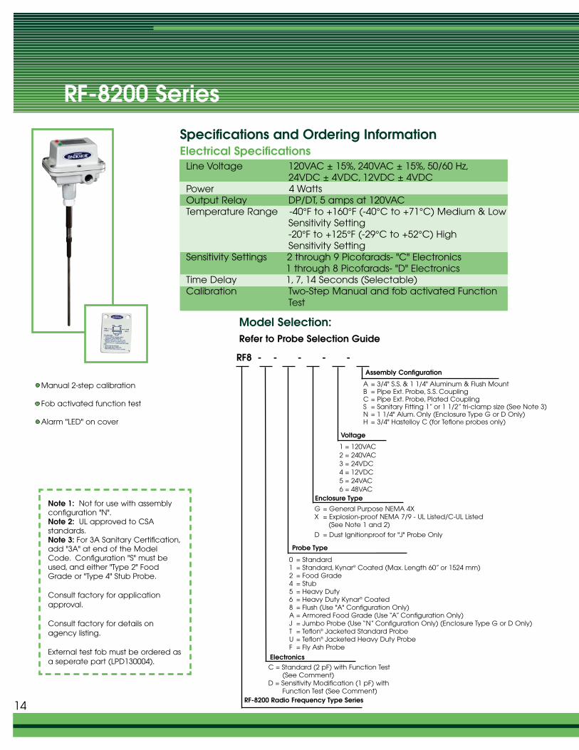
RF-8200 Series
Line Voltage 120VAC ± 15%, 240VAC ± 15%, 50/60 Hz,24VDC ± 4VDC, 12VDC ± 4VDC
Power 4 WattsOutput Relay DP/DT, 5 amps at 120VACTemperature Range -40°F to +160°F (-40°C to +71°C) Medium & Low
Sensitivity Setting-20°F to +125°F (-29°C to +52°C) High Sensitivity Setting
Sensitivity Settings 2 through 9 Picofarads- "C" Electronics1 through 8 Picofarads- "D" Electronics
Time Delay 1, 7, 14 Seconds (Selectable)Calibration Two-Step Manual and fob activated Function
Test
Assembly Configuration
A = 3/4" S.S. & 1 1/4" Aluminum & Flush MountB = Pipe Ext. Probe, S.S. CouplingC = Pipe Ext. Probe, Plated CouplingS = Sanitary Fitting 1” or 1 1/2” tri-clamp size (See Note 3)N = 1 1/4" Alum. Only (Enclosure Type G or D Only)H = 3/4" Hastelloy C (for Teflon® probes only)
Voltage
1 = 120VAC2 = 240VAC3 = 24VDC4 = 12VDC5 = 24VAC6 = 48VAC
Enclosure Type
G = General Purpose NEMA 4XX = Explosion-proof NEMA 7/9 - UL Listed/C-UL Listed
(See Note 1 and 2)
D = Dust Ignitionproof for "J" Probe Only
0 = Standard1 = Standard, Kynar® Coated (Max. Length 60” or 1524 mm)2 = Food Grade4 = Stub5 = Heavy Duty6 = Heavy Duty Kynar® Coated8 = Flush (Use "A" Configuration Only)A = Armored Food Grade (Use “A” Configuration Only)J = Jumbo Probe (Use “N” Configuration Only) (Enclosure Type G or D Only)T = Teflon® Jacketed Standard ProbeU = Teflon® Jacketed Heavy Duty ProbeF = Fly Ash Probe
Probe Type
RF8 - - - - -
Specifications and Ordering InformationElectrical Specifications
Model Selection:Refer to Probe Selection Guide
ElectronicsC = Standard (2 pF) with Function Test
(See Comment)D = Sensitivity Modification (1 pF) with
Function Test (See Comment)RF-8200 Radio Frequency Type Series
Manual 2-step calibration
Fob activated function test
Alarm "LED" on cover
Note 1: Not for use with assemblyconfiguration "N".Note 2: UL approved to CSA standards.Note 3: For 3A Sanitary Certification,add "3A" at end of the ModelCode. Configuration "S" must beused, and either "Type 2" FoodGrade or "Type 4" Stub Probe.
Consult factory for applicationapproval.
Consult factory for details onagency listing.
External test fob must be ordered asa seperate part (LPD130004).
14
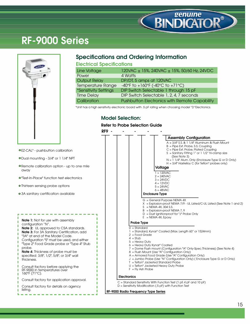
RF-9000 Series
Line Voltage 120VAC ± 15%, 240VAC ± 15%, 50/60 Hz, 24VDCPower 4 WattsOutput Relay DP/DT, 5 amps at 120VACTemperature Range -40°F to +160°F (-40°C to +71°C) *Sensitivity Settings DIP Switch Selectable 1 through 15 pFTime Delay DIP Switch Selectable 1, 2, 4, 7 secondsCalibration Pushbutton Electronics with Remote Capability
Assembly ConfigurationA = 3/4" S.S. & 1 1/4" Aluminum & Flush MountB = Pipe Ext. Probe, S.S. CouplingC = Pipe Ext. Probe, Plated CouplingS = Sanitary Fitting 1” or 1 1/2” tri-clamp size
(See Note 3)N = 1 1/4" Alum. Only (Enclosure Type G or D Only)H = 3/4" Hastelloy C (for Teflon® probes only)
Voltage1 = 120VAC2 = 240VAC3 = 24VDC4 = 12VDC5 = 24VAC6 = 48VAC
Enclosure Type
G = General Purpose NEMA 4XX = Explosion-proof NEMA 7/9 - UL Listed/C-UL Listed (See Note 1 and 2)S = NEMA 4X, 304 S.S.B = Explosion-proof NEMA 7, 9 D = Dust Ignitionproof for "J" Probe OnlyE = NEMA 4X, Epoxy
0 = Standard1 = Standard, Kynar® Coated (Max. Length 60” or 1524mm)2 = Food Grade4 = Stub5 = Heavy Duty6 = Heavy Duty Kynar® Coated7 = Dome Flush mount (Configuration "A" Only-Spec.Thickness) (See Note 4)8 = Flush Mount (Use "A" Configuration Only)A = Armored Food Grade (Use "A" Configuration Only)J = Jumbo Probe (Use “N” Configuration Only) ( Enclosure Type G or D Only)T = Teflon® Jacketed Standard ProbeU = Teflon® Jacketed Heavy Duty ProbeF = Fly Ash Probe
Probe Type
RF9 - - - - -
Specifications and Ordering InformationElectrical Specifications
Model Selection:Refer to Probe Selection Guide
Electronics
C = Standard Sensitivity With Function Test (1 pF, 4 pF and 10 pF)D = Sensitivity Modification (.5 pF) with Function Test
RF-9000 Radio Frequency Type Series
EZ-CAL® - pushbutton calibration
Dual mounting - 3/4" or 1 1/4" NPT
Remote calibration option - up to one mileaway
"Test-In-Place" function test electronics
Thirteen sensing probe options
3A sanitary certification available
Note 1: Not for use with assembly configuration “N”.Note 2: UL approved to CSA standards.Note 3: For 3A Sanitary Certification, add"3A" at end of the Model Code.Configuration "S" must be used, and either"Type 2" Food Grade probe or "Type 4" Stubprobe.Note 4: Thickness of probe must be specified: 3/8", 1/2", 5/8", or 3/4" wall thickness.
Consult factory before applying the RF-9000 in temperatures over 160°F (71°C).
Consult factory for application approval.
Consult factory for details on agency listing.
*Unit has a high sensitivity electronic board with .5 pF rating when choosing model “D”Electronics.
15
Specifications and Ordering InformationElectrical Specifications
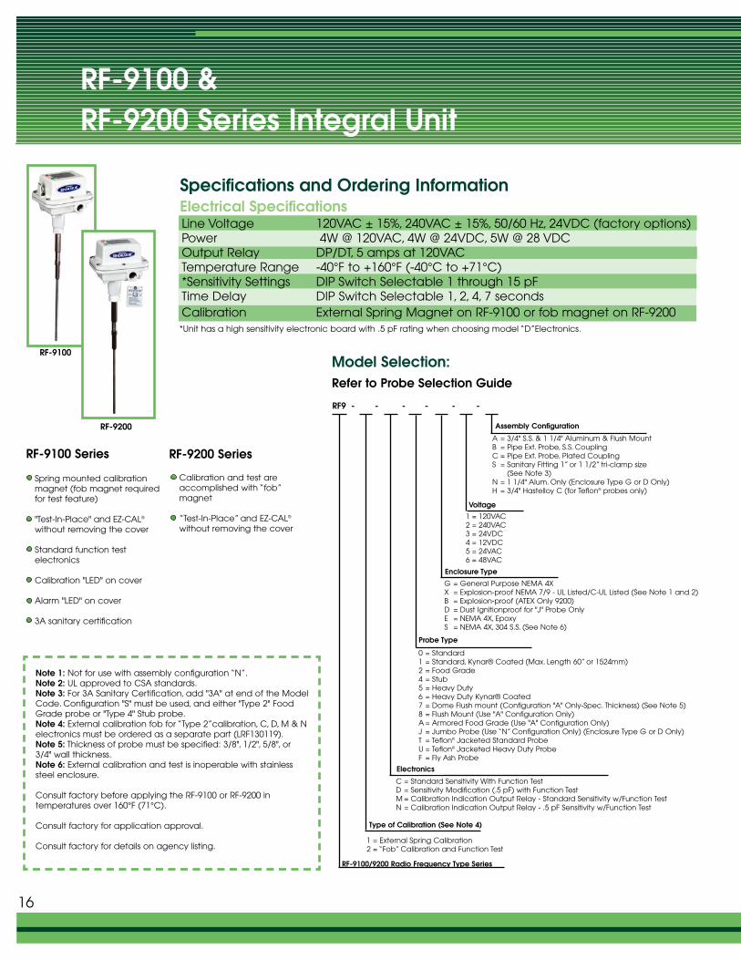
Spring mounted calibrationmagnet (fob magnet requiredfor test feature)
"Test-In-Place" and EZ-CAL®
without removing the cover
Standard function test electronics
Calibration "LED" on cover
Alarm "LED" on cover
3A sanitary certification
Note 1: Not for use with assembly configuration “N”.Note 2: UL approved to CSA standards.Note 3: For 3A Sanitary Certification, add "3A" at end of the ModelCode. Configuration "S" must be used, and either "Type 2" FoodGrade probe or "Type 4" Stub probe.Note 4: External calibration fob for “Type 2”calibration, C, D, M & Nelectronics must be ordered as a separate part (LRF130119).Note 5: Thickness of probe must be specified: 3/8", 1/2", 5/8", or3/4" wall thickness.Note 6: External calibration and test is inoperable with stainlesssteel enclosure.
Consult factory before applying the RF-9100 or RF-9200 in temperatures over 160°F (71°C).
Consult factory for application approval.
Consult factory for details on agency listing.
*Unit has a high sensitivity electronic board with .5 pF rating when choosing model “D”Electronics.
RF-9100 Series
Calibration and test areaccomplished with “fob”magnet
“Test-In-Place” and EZ-CAL®
without removing the cover
RF9 - - - - - -
Assembly Configuration
Probe Type
C = Standard Sensitivity With Function Test D = Sensitivity Modification (.5 pF) with Function TestM = Calibration Indication Output Relay - Standard Sensitivity w/Function TestN = Calibration Indication Output Relay - .5 pF Sensitivity w/Function Test
RF-9100/9200 Radio Frequency Type Series
A = 3/4" S.S. & 1 1/4" Aluminum & Flush MountB = Pipe Ext. Probe, S.S. CouplingC = Pipe Ext. Probe, Plated CouplingS = Sanitary Fitting 1” or 1 1/2” tri-clamp size
(See Note 3)N = 1 1/4" Alum. Only (Enclosure Type G or D Only)H = 3/4" Hastelloy C (for Teflon® probes only)
1 = 120VAC2 = 240VAC3 = 24VDC4 = 12VDC5 = 24VAC6 = 48VAC
Enclosure Type
G = General Purpose NEMA 4XX = Explosion-proof NEMA 7/9 - UL Listed/C-UL Listed (See Note 1 and 2)B = Explosion-proof (ATEX Only 9200)D = Dust Ignitionproof for "J" Probe OnlyE = NEMA 4X, EpoxyS = NEMA 4X, 304 S.S. (See Note 6)
0 = Standard1 = Standard, Kynar® Coated (Max. Length 60” or 1524mm)2 = Food Grade4 = Stub5 = Heavy Duty6 = Heavy Duty Kynar® Coated7 = Dome Flush mount (Configuration "A" Only-Spec. Thickness) (See Note 5)8 = Flush Mount (Use "A" Configuration Only)A = Armored Food Grade (Use "A" Configuration Only)J = Jumbo Probe (Use “N” Configuration Only) (Enclosure Type G or D Only)T = Teflon® Jacketed Standard ProbeU = Teflon® Jacketed Heavy Duty ProbeF = Fly Ash Probe
Electronics
Type of Calibration (See Note 4)
1 = External Spring Calibration 2 = “Fob” Calibration and Function Test
Model Selection:Refer to Probe Selection Guide
RF-9100
RF-9200
16
RF-9100 & RF-9200 Series Integral Unit
Voltage
Line Voltage 120VAC ± 15%, 240VAC ± 15%, 50/60 Hz, 24VDC (factory options)Power 4W @ 120VAC, 4W @ 24VDC, 5W @ 28 VDCOutput Relay DP/DT, 5 amps at 120VACTemperature Range -40°F to +160°F (-40°C to +71°C) *Sensitivity Settings DIP Switch Selectable 1 through 15 pFTime Delay DIP Switch Selectable 1, 2, 4, 7 secondsCalibration External Spring Magnet on RF-9100 or fob magnet on RF-9200
RF-9200 Series
RF-10000 Series Electronics
Voltage1 = 120VAC2 = 240VAC3 = 24VDC4 = 12VDC5 = 24VAC6 = 48VAC
Enclosure Type
G= General Purpose NEMA 4X (See Note 2)X = Explosion-proof NEMA 7/9 - UL Listed/C-UL
(See Note 1 and 3) S = NEMA 4X, 304 Stainless Steel E = NEMA 4X, Epoxy
C = Standard Sensitivity With Function TestD = Sensitivity Modification (.5 pF) with Function TestK = Standard (1 pF) with Function Test and for “Type 7”
Probe Only
Probe Requirement
RF10 - E - - - -
Specifications and Ordering InformationElectrical Specifications
Model Selection:Refer to Probe Selection Guide
Electronic Unit
(Probe and Cable Are Separate Items)
RF-10000 Radio Frequency Type
Note 1: UL approved to CSA standards.Note 2: The total length of cable cannot exceed 75 feet (23m) from theelectronics.Note 3: Maximum cable distancebetween electronics and probe onexplosion-proof is 50 feet (15.24m).
Consult factory for applicationapproval.
*Unit has a high sensitivity electronic board with .5 pF rating when choosing model “D”Electronics.
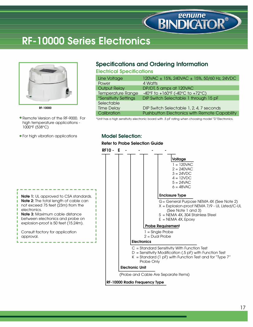
RF-10000
Remote Version of the RF-9000. Forhigh temperature applications -1000°F (538°C)
For high vibration applications
1 = Single Probe2 = Dual Probe
Electronics
Line Voltage 120VAC ± 15%, 240VAC ± 15%, 50/60 Hz, 24VDCPower 4 WattsOutput Relay DP/DT, 5 amps at 120VACTemperature Range -40°F to +160°F (-40°C to +72°C) *Sensitivity Settings DIP Switch Selectable 1 through 15 pFSelectableTime Delay DIP Switch Selectable 1, 2, 4, 7 secondsCalibration Pushbutton Electronics with Remote Capability
17
RF-11000 & RF-12000 Series Electronics
Voltage
1 = 120VAC2 = 240VAC3 = 24VDC4 = 12VDC5 = 24VAC6 = 48VAC
Enclosure Type
G = General Purpose NEMA 4X X = Explosion-proof NEMA 7/9 - UL Listed/C-UL
Listed (See Note 2)E = NEMA 4X, Epoxy
C = Standard Sensitivity With Function TestK = Standard (1 pF) with Function Test and for “Type 7”
Probe OnlyM= Calibration Indication Output Relay - Standard
Sensitivity w/Function TestN = Calibration Indication Output Relay- .5 pF Sensitivity
w/Function Test
Probe Requirement
RF1 - - E - - - -
Specifications and Ordering InformationElectrical Specifications
Model Selection:Refer to Probe Selection Guide
Electronic Unit(Probe and Cable Are Separate Items)
RF-11000/12000 Radio Frequency Type Series
Note 1: External calibration“fob” must be ordered as aseparate part (LRF130115).Note 2: UL approved to CSAstandards.
Consult factory for details onagency listing.
*Unit has a high sensitivity electronic board with .5 pF rating when choosing model “D”Electronics.
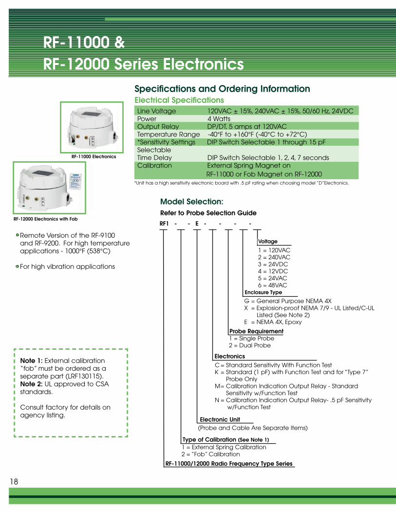
RF-11000 Electronics
RF-12000 Electronics with Fob
Remote Version of the RF-9100 and RF-9200. For high temperatureapplications - 1000°F (538°C)
For high vibration applications
1 = Single Probe2 = Dual Probe
Electronics
Type of Calibration (See Note 1)1 = External Spring Calibration2 = “Fob” Calibration
Line Voltage 120VAC ± 15%, 240VAC ± 15%, 50/60 Hz, 24VDCPower 4 WattsOutput Relay DP/DT, 5 amps at 120VACTemperature Range -40°F to +160°F (-40°C to +72°C) *Sensitivity Settings DIP Switch Selectable 1 through 15 pFSelectableTime Delay DIP Switch Selectable 1, 2, 4, 7 secondsCalibration External Spring Magnet on
RF-11000 or Fob Magnet on RF-12000
18
Line Voltage 120VAC ± 15%, 240VAC ± 15%, 50/60 Hz, 24VDC ± 4VDC,12VDC ± 4VDC
Power 4 WattsOutput Relay DP/DT, 5 amps at 120VACTemperature Range -40°F to +160°F (-40°C to +71°C) Medium and Low
Sensitivity Setting-20°F TO +125°F (-20°C to + 52°C) High Sensitivity Setting
Sensitivity Settings 2 through 9 Picofarads - “0” Electronics for RF-17000 and “C” Electronics for RF -18000
Time Delay 1, 7, 14 seconds (Selectable)Calibration Two-Step Manual for RF-17000 and fob activated function
test on RF-18000
Voltage1 = 120VAC2 = 240VAC3 = 24VDC4 = 12VDC5 = 24VAC6 = 48VAC7 = 100VAC
Enclosure Type
G = General Purpose NEMA 4X (See Note 1 and 2)X = Explosion-proof NEMA 7, 9 (See Note 4)
C = Standard Sensitivity With Function Test (RF-18000 Only)K = Standard (2 pF) with Function Test and for “Type 7” Probe
Only (RF-18000 Only)O = Standard Sensitivity (RF-17000 Only)G = Standard (2 pF) for “Type 7” Probe Only (RF-17000 Only)
Probe Requirement
RF - E - - - -
Specifications and Ordering InformationElectrical Specifications
Model Selection:Refer to Probe Selection Guide
Electronic Unit
(Probe and Cable Are Separate Items)
Note 1: The total length of cable isnot to exceed 40 feet (12.19m) fromthe electronics.Note 2: UL approved to CSA standards.Note 3: External test and alarm “fob”must be ordered as a separate part (LPD130005).Note 4: Maximum cable distancebetween electronics and probe onexplosion-proof unit is 30 feet (9.14m).
1 = Single Probe
Electronics
RF-17000/18000 Radio Frequency Type Series
17 = RF-17000 Radio Frequency Type Series18 = RF-18000 Radio Frequency Type Series (See Note 3)
19
RF 17000 & RF-18000 Series Electronics
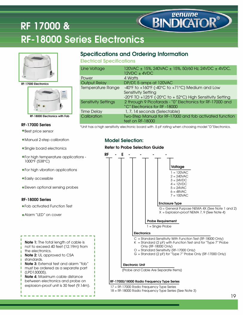
RF-17000 Electronics
RF-18000 Electronics with Fob
Best price sensor
Manual 2-step calibration
Single board electronics
For high temperature applications -1000°F (538°C)
For high vibration applications
Easily accessible
Eleven optional sensing probes
Fob activated Function Test
Alarm “LED” on cover
RF-18000 Series
RF-17000 Series *Unit has a high sensitivity electronic board with .5 pF rating when choosing model “D”Electronics.
RF-10000, RF-11000, RF-12000,
RF-17000 and RF-18000 Probe Selection
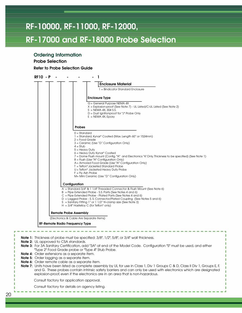
Enclosure Material1 = Bindicator Standard Enclosure
Enclosure Type
G = General Purpose NEMA 4XX = Explosion-proof (See Note 7) - UL Listed/C-UL Listed (See Note 2)S = NEMA 4X, 304 S.S.D = Dust Ignitionproof for "J" Probe OnlyE = NEMA 4X, Epoxy
0 = Standard1 = Standard, Kynar® Coated (Max. Length 60” or 1524mm)2 = Food Grade3 = Ceramic (Use “D” Configuration Only)4 = Stub5 = Heavy Duty6 = Heavy Duty Kynar® Coated7 = Dome Flush mount (Config. "A" and Electronics “K’Only, Thickness to be specified) (See Note 1)8 = Flush (Use "A" Configuration Only)A= Armored Food Grade (Use "A" Configuration Only)T = Teflon® Jacketed Standard ProbeU = Teflon® Jacketed Heavy Duty ProbeF = Fly Ash ProbeM= Mini Ceramic (Use “D” Configuration Only)
Probes
RF10 - P - - - - 1
Ordering InformationProbe SelectionRefer to Probe Selection Guide
ConfigurationA = Standard 3/4" & 1 1/4" Threaded Connector & Flush Mount (See Note 6)B = Pipe Extended Probe - S.S. Parts (See Notes 4 and 6)C = Pipe Extended Probe - Plated Parts (See Notes 4 and 6)D = Lagged Probe - S. S. Connector/Plated Coupling (See Notes 5 and 6)S = Sanitary Fitting 1” or 1 1/2” tri-clamp size (See Note 3)H = 3/4" Hastelloy C (for Teflon® only)
RF-Remote Radio Frequency Type
Note 1: Thickness of probe must be specified: 3/8", 1/2", 5/8", or 3/4" wall thickness.Note 2: UL approved to CSA standards.Note 3: For 3A Sanitary Certification, add "3A" at end of the Model Code. Configuration "S" must be used, and either
"Type 2" Food Grade probe or "Type 4" Stub Probe.Note 4: Order extensions as a separate item.Note 5: Order lagging as a separate item.Note 6: Order remote cable as a separate item.Note 7: Units have been listed as complete assembly by UL for use in Class 1, Div 1 Groups C & D, Class II Div 1, Groups E, F,
and G. These probes contain intrinsic safety barriers and can only be used with electronics which are designated explosion-proof, even if the electronics are in an area that is non-hazardous.
Consult factory for application approval.
Consult factory for details on agency listing.
Remote Probe Assembly
(Electronics & Cable Are Separate Items)
20
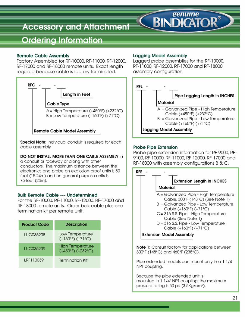
Remote Cable AssemblyFactory Assembled for RF-10000, RF-11000, RF-12000,RF-17000 and RF-18000 remote units. Exact lengthrequired because cable is factory terminated.
Special Note: Individual conduit is required for eachcable assembly.
DO NOT INSTALL MORE THAN ONE CABLE ASSEMBLY ina conduit or raceway or along with other conductors. The maximum distance between theelectronics and probe on explosion-proof units is 50feet (15.24m) and on general-purpose units is 75 feet (23m).
Length in Feet
Cable Type
A= High Temperature (+450°F) (+232°C)B = Low Temperature (+160°F) (+71°C)
Remote Cable Model Assembly
Bulk Remote Cable --- UndeterminedFor the RF-10000, RF-11000, RF-12000, RF-17000 andRF-18000 remote units. Order bulk cable plus onetermination kit per remote unit.
RFC - -
Lagging Model AssemblyLagged probe assemblies for the RF-10000,RF-11000, RF-12000, RF-17000 and RF-18000assembly configuration.
Pipe Lagging Length in INCHES
Material
A = Galvanized Pipe - High TemperatureCable (+450°F) (+232°C)
B = Galvanized Pipe - Low TemperatureCable (+160°F) (+71°C)
Lagging Model Assembly
RFL - -
Probe Pipe ExtensionProbe pipe extension information for RF-9000, RF-9100, RF-10000, RF-11000, RF-12000, RF-17000 andRF-18000 with assembly configurations B & C.
Note 1: Consult factory for applications between300°F (148°C) and 460°F (238°C).
Pipe extended models can mount only in a 1 1/4"NPT coupling.
Because the pipe extended unit is mounted in 1 1/4" NPT coupling, the maximum pressure rating is 50 psi (3.5Kg/cm2).
Extension Length in INCHES
Material
A = Galvanized Pipe - High TemperatureCable, 300°F (148°C) (See Note 1)
B = Galvanized Pipe - Low Temperature Cable (+160°F) (+71°C)
C= 316 S.S. Pipe - High Temperature Cable (See Note 1)
D = 316 S.S. Pipe - Low TemperatureCable (+160°F) (+71°C)
Extension Model Assembly
RFE - -
21
Accessory and Attachment
Ordering Information
Product Code
LUC035208
LUC035209
LRF110039
Description
Low Temperature(+160°F) (+71°C)
High Temperature(+450°F) (+232°C)
Termination Kit
Accessory and AttachmentOrdering Information
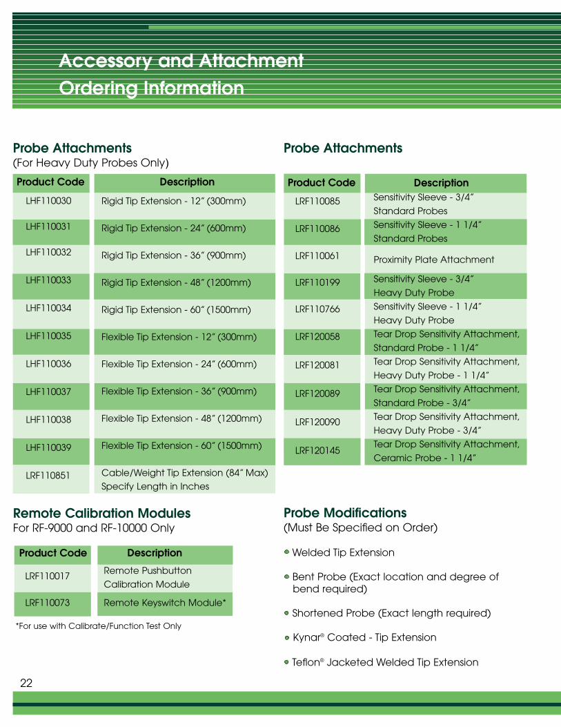
Probe Attachments(For Heavy Duty Probes Only)
Probe Attachments
Remote Calibration ModulesFor RF-9000 and RF-10000 Only
*For use with Calibrate/Function Test Only
22
Probe Modifications(Must Be Specified on Order)
Welded Tip Extension
Bent Probe (Exact location and degree ofbend required)
Shortened Probe (Exact length required)
Kynar® Coated - Tip Extension
Teflon® Jacketed Welded Tip Extension
Product Code
LHF110030
LHF110031
LHF110032
LHF110033
LHF110034
LHF110035
LHF110036
LHF110037
LHF110038
LHF110039
LRF110851
Description
Rigid Tip Extension - 12” (300mm)
Rigid Tip Extension - 24” (600mm)
Rigid Tip Extension - 36” (900mm)
Rigid Tip Extension - 48” (1200mm)
Rigid Tip Extension - 60” (1500mm)
Flexible Tip Extension - 12” (300mm)
Flexible Tip Extension - 24” (600mm)
Flexible Tip Extension - 36” (900mm)
Flexible Tip Extension - 48” (1200mm)
Flexible Tip Extension - 60” (1500mm)
Cable/Weight Tip Extension (84” Max)
Specify Length in Inches
Product Code Description
LRF110085
LRF110086
LRF110061
LRF110199
LRF110766
LRF120058
LRF120081
LRF120089
LRF120090
LRF120145
Sensitivity Sleeve - 3/4”
Standard Probes
Sensitivity Sleeve - 1 1/4”
Standard Probes
Proximity Plate Attachment
Sensitivity Sleeve - 3/4”
Heavy Duty Probe
Sensitivity Sleeve - 1 1/4”
Heavy Duty Probe
Tear Drop Sensitivity Attachment,
Standard Probe - 1 1/4”
Tear Drop Sensitivity Attachment,
Heavy Duty Probe - 1 1/4”
Tear Drop Sensitivity Attachment,
Standard Probe - 3/4”
Tear Drop Sensitivity Attachment,
Heavy Duty Probe - 3/4”
Tear Drop Sensitivity Attachment,
Ceramic Probe - 1 1/4”
Product Code
LRF110017
LRF110073
Remote Pushbutton
Calibration Module
Remote Keyswitch Module*
Description
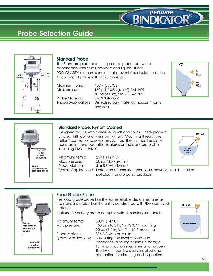
Standard ProbeThe Standard probe is a multi-purpose probe that worksdependably with solids, powders and liquids. It has PRO-GUARD® element sensors that prevent false indications dueto coating of probe with sticky materials.
Maximum temp: 450°F (232°C)Max. pressure: 150 psi (10.5 kg/cm2) 3/4" NPT
50 psi (3.5 kg/cm2) 1 1/4" NPTProbe Material: 316 S.S./Ryton®
Typical Applications: Detecting bulk materials, liquids in tanks and bins.
Standard Probe, Kynar® CoatedDesigned for use with corrosive liquids and solids. Entire probe iscoated with corrosion-resistant Kynar®. Mounting threads areTeflon® coated for corrosion resistance. The unit has the sameconstruction and operation features as the standard probeincluding PRO-GUARD®.
Maximum temp: 250°F (121°C)Max. pressure: 50 psi (3.5 kg/cm2)Probe Material: 316 S.S. with Kynar®
Typical Applications: Detection of corrosive chemicals, powders, liquids or solids,petroleum and organic products.
Food Grade ProbeThe food grade probe has the same reliable design features as the standard probe, but the unit is constructed with FDA approvedmaterial.Optional Sanitary probe complies with sanitary standards.
Maximum temp: 300°F (149°C)Max. pressure: 150 psi (10.5 kg/cm2) 3/4" mounting
50 psi (3.5 kg/cm2) 1 1/4" mountingProbe Material: 316 S.S. with polysulfoneTypical Applications: Measuring the level of food and
pharmaceutical ingredients in storage tanks, production machines and hoppers.The 3A unit can be easily installed and dismantled for cleaning and inspection.
Corrosive material or
liquid
23
Probe Selection Guide
HighlevelRF unit
LowlevelRF unit
Probe Selection Guide
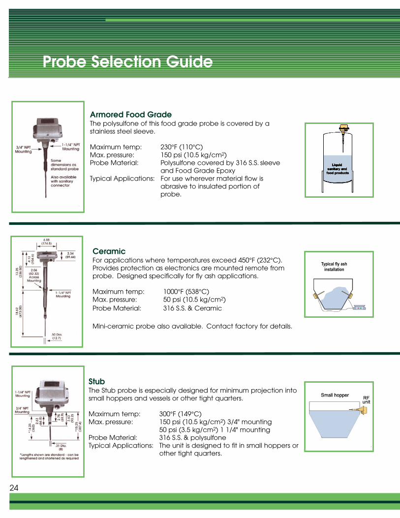
Armored Food GradeThe polysulfone of this food grade probe is covered by a stainless steel sleeve.
Maximum temp: 230°F (110°C)Max. pressure: 150 psi (10.5 kg/cm2)Probe Material: Polysulfone covered by 316 S.S. sleeve
and Food Grade EpoxyTypical Applications: For use wherever material flow is
abrasive to insulated portion of probe.
CeramicFor applications where temperatures exceed 450°F (232°C).Provides protection as electronics are mounted remote fromprobe. Designed specifically for fly ash applications.
Maximum temp: 1000°F (538°C)Max. pressure: 50 psi (10.5 kg/cm2)Probe Material: 316 S.S. & Ceramic
Mini-ceramic probe also available. Contact factory for details.
StubThe Stub probe is especially designed for minimum projection intosmall hoppers and vessels or other tight quarters.
Maximum temp: 300°F (149°C)Max. pressure: 150 psi (10.5 kg/cm2) 3/4" mounting
50 psi (3.5 kg/cm2) 1 1/4" mountingProbe Material: 316 S.S. & polysulfone Typical Applications: The unit is designed to fit in small hoppers or
other tight quarters.
24
Typical fly ashinstallation
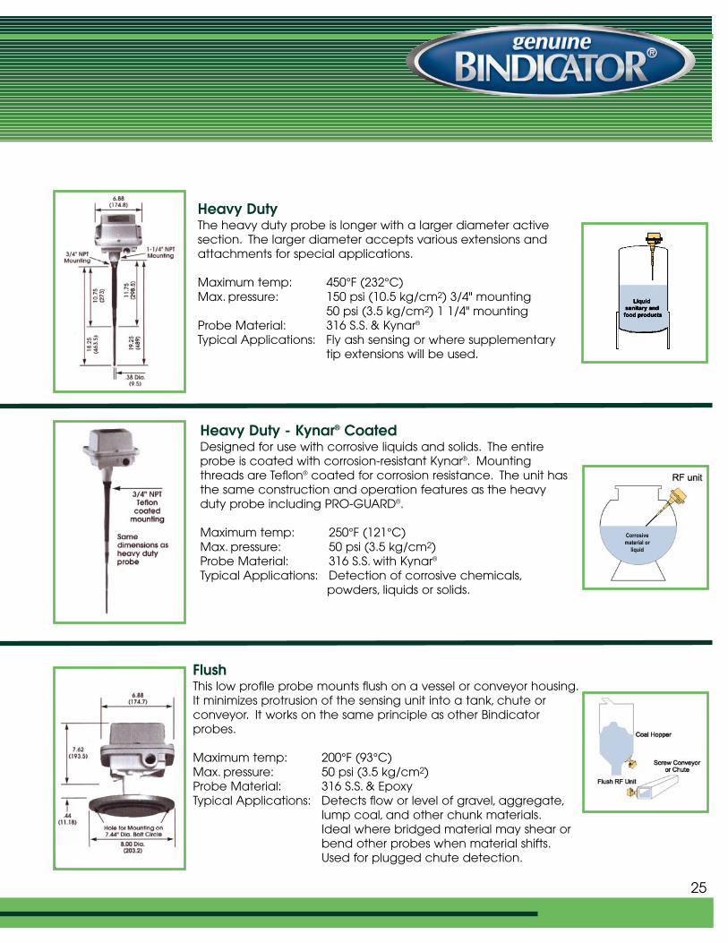
Heavy DutyThe heavy duty probe is longer with a larger diameter activesection. The larger diameter accepts various extensions andattachments for special applications.
Maximum temp: 450°F (232°C)Max. pressure: 150 psi (10.5 kg/cm2) 3/4" mounting
50 psi (3.5 kg/cm2) 1 1/4" mountingProbe Material: 316 S.S. & Kynar®
Typical Applications: Fly ash sensing or where supplementary tip extensions will be used.
Heavy Duty - Kynar® CoatedDesigned for use with corrosive liquids and solids. The entireprobe is coated with corrosion-resistant Kynar®. Mountingthreads are Teflon® coated for corrosion resistance. The unit hasthe same construction and operation features as the heavyduty probe including PRO-GUARD®.
Maximum temp: 250°F (121°C)Max. pressure: 50 psi (3.5 kg/cm2)Probe Material: 316 S.S. with Kynar®
Typical Applications: Detection of corrosive chemicals,powders, liquids or solids.
FlushThis low profile probe mounts flush on a vessel or conveyor housing.It minimizes protrusion of the sensing unit into a tank, chute or conveyor. It works on the same principle as other Bindicatorprobes.
Maximum temp: 200°F (93°C)Max. pressure: 50 psi (3.5 kg/cm2)Probe Material: 316 S.S. & EpoxyTypical Applications: Detects flow or level of gravel, aggregate,
lump coal, and other chunk materials.Ideal where bridged material may shear or bend other probes when material shifts.Used for plugged chute detection.
Corrosive material or
liquid
25
Probe Selection Guide
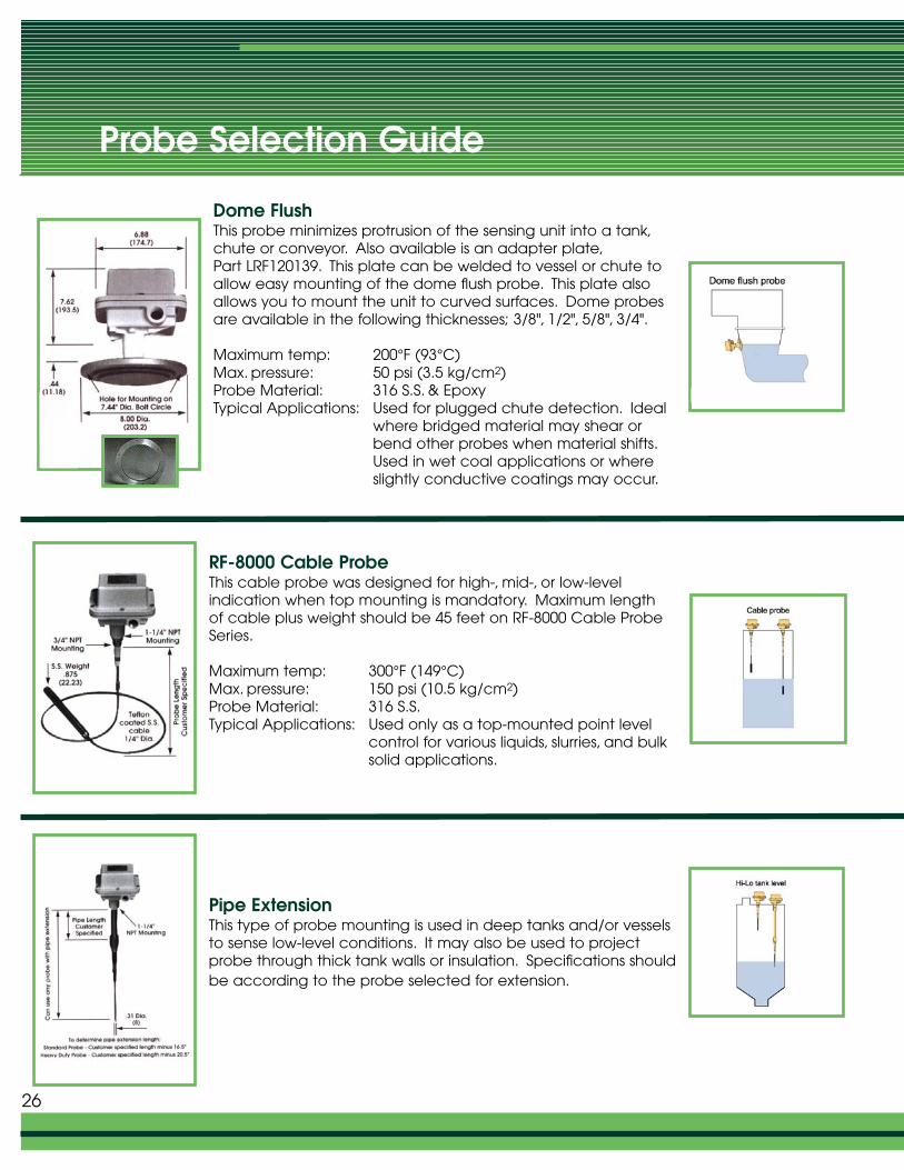
Dome FlushThis probe minimizes protrusion of the sensing unit into a tank,chute or conveyor. Also available is an adapter plate,Part LRF120139. This plate can be welded to vessel or chute toallow easy mounting of the dome flush probe. This plate alsoallows you to mount the unit to curved surfaces. Dome probesare available in the following thicknesses; 3/8", 1/2", 5/8", 3/4".
Maximum temp: 200°F (93°C)Max. pressure: 50 psi (3.5 kg/cm2)Probe Material: 316 S.S. & EpoxyTypical Applications: Used for plugged chute detection. Ideal
where bridged material may shear or bend other probes when material shifts.Used in wet coal applications or where slightly conductive coatings may occur.
RF-8000 Cable ProbeThis cable probe was designed for high-, mid-, or low-level indication when top mounting is mandatory. Maximum lengthof cable plus weight should be 45 feet on RF-8000 Cable ProbeSeries.
Maximum temp: 300°F (149°C)Max. pressure: 150 psi (10.5 kg/cm2)Probe Material: 316 S.S.Typical Applications: Used only as a top-mounted point level
control for various liquids, slurries, and bulk solid applications.
Pipe ExtensionThis type of probe mounting is used in deep tanks and/or vesselsto sense low-level conditions. It may also be used to projectprobe through thick tank walls or insulation. Specifications shouldbe according to the probe selected for extension.
26
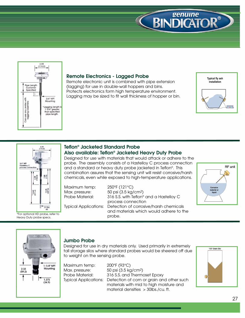
Remote Electronics - Lagged ProbeRemote electronic unit is combined with pipe extension(lagging) for use in double-wall hoppers and bins.Protects electronics form high temperature environment.Lagging may be sized to fit wall thickness of hopper or bin.
27
Teflon® Jacketed Standard ProbeAlso available: Teflon® Jacketed Heavy Duty ProbeDesigned for use with materials that would attack or adhere to theprobe. The assembly consists of a Hastelloy C process connectionand a standard or heavy duty probe jacketed in Teflon®. This combination assures that the sensing unit will resist corrosive/harshchemicals, even while exposed to high-temperature applications.
Maximum temp: 250°F (121°C)Max. pressure: 50 psi (3.5 kg/cm2)Probe Material: 316 S.S. with Teflon® and a Hastelloy C
process connectionTypical Applications: Detection of corrosive/harsh chemicals
and materials which would adhere to the probe.
Jumbo ProbeDesigned for use in dry materials only. Used primarily in extremelytall storage silos where standard probes would be sheered off dueto weight on the sensing probe.
Maximum temp: 200°F (93°C)Max. pressure: 50 psi (3.5 kg/cm2)Probe Material: 316 S.S. and Thermoset EpoxyTypical Applications: Detection of corn or grain and other such
materials with mid to high moisture and material densities > 30lbs./cu. ft.
*For optional HD probe, refer toHeavy Duty probe specs.
Typical fly ashinstallation
Corrosive material or
liquid
Probe Selection Guide
Bindicator offers a complete range of Level and Material Handling Controls
LRF180019 Rev. B
For information, specifications, installation instructions and engineering help with any Bindicator product, contact Bindicator or your localauthorized representative.
Bindicator® is a registered trademark of Venture Measurement.
150 Venture Boulevard · Spartanburg, SC 29306Tel: (800) 778-9242 · (864) 574-8060 Fax: (864) 574-8063E-mail: [email protected]
2005 All rights reserved.All data subject to change without notice.
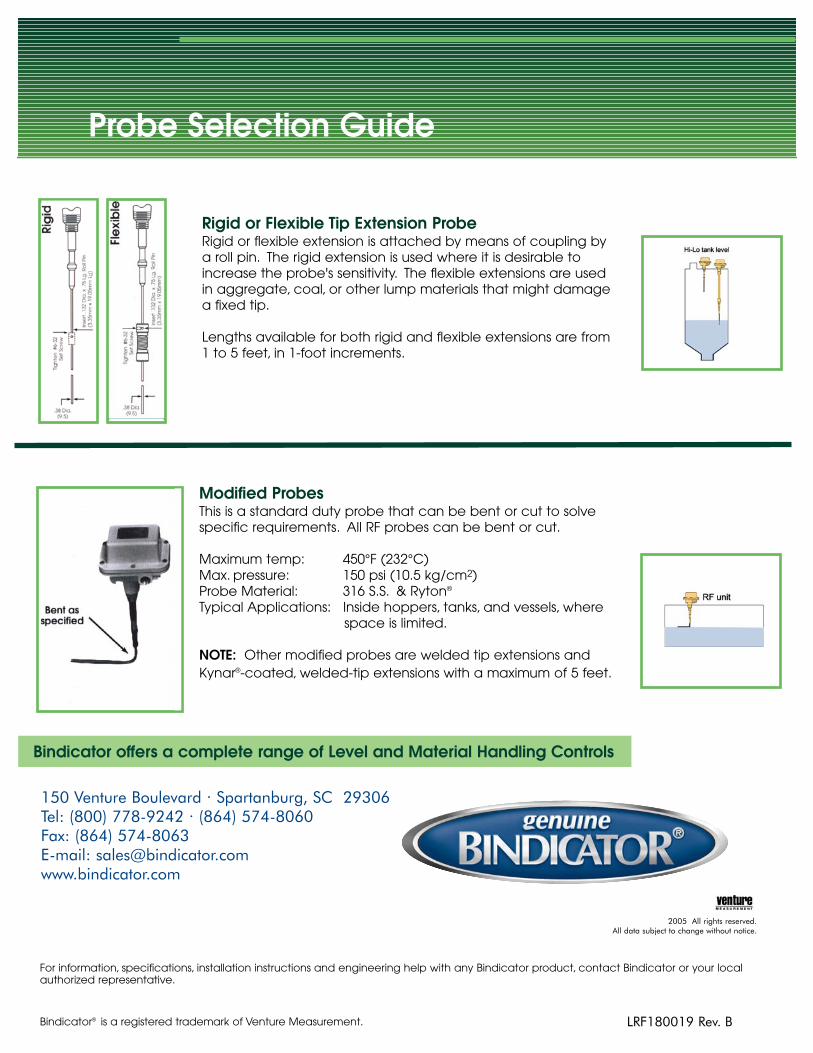
Rigid or Flexible Tip Extension ProbeRigid or flexible extension is attached by means of coupling bya roll pin. The rigid extension is used where it is desirable toincrease the probe's sensitivity. The flexible extensions are usedin aggregate, coal, or other lump materials that might damagea fixed tip.
Lengths available for both rigid and flexible extensions are from1 to 5 feet, in 1-foot increments.
Modified ProbesThis is a standard duty probe that can be bent or cut to solve specific requirements. All RF probes can be bent or cut.
Maximum temp: 450°F (232°C)Max. pressure: 150 psi (10.5 kg/cm2)Probe Material: 316 S.S. & Ryton®
Typical Applications: Inside hoppers, tanks, and vessels, where space is limited.
NOTE: Other modified probes are welded tip extensions andKynar®-coated, welded-tip extensions with a maximum of 5 feet.