radio remote control uc system - welotec global … · -54- fr en de uc 323882g for maximum safety...
TRANSCRIPT

DEUC 323882G -51-EN FR
Installation and usertechnical manual
RRRRRadio radio radio radio radio remoteemoteemoteemoteemotecontrcontrcontrcontrcontrololololol
UC SYUC SYUC SYUC SYUC SYSTEMSTEMSTEMSTEMSTEM
DE- 5 2 - UC 323882GENFR
- CONTENTS -- CONTENTS -- CONTENTS -- CONTENTS -- CONTENTS -General safety rules ........................................................ p. 54
1 Description of UC radio remote control ...................... p. 561.1 Unpacking the products ...................................................................... p. 581.2 Delivery configuration ........................................................................ p. 59
2 Type and specification of function buttons on UCE .. p. 602.1 Type and number of buttons .............................................................. p. 602.2 Function button interlocking ................................................................ p. 602.3 Correspondence between function buttons and receiver relays ........ p. 61
3 Product identification ...................................................... p. 623.1 UCE transmitter .................................................................................. p. 623.2 UCR receiver ...................................................................................... p. 633.3 Standard unit reference ...................................................................... p. 643.4 Accessories ........................................................................................ p. 64
4 Technical characteristics ................................................ p. 654.1 UCE transmitter ................................................................................ p. 654.1.1 Identity code ....................................................................................... p. 664.1.2 Electronic key ..................................................................................... p. 664.1.3 "Standby" function (automatic shutdown of UCE) ............................. p. 684.2 UCR receiver ..................................................................................... p. 694.2.1 Connection to relay outputs ............................................................... p. 704.2.2 Relay characteristics .......................................................................... p. 704.2.3 Protection of receiver board and relays ............................................. p. 724.3 UWB plug-in battery pack ............................................................... p. 734.3.1 Battery pack storage precaution ......................................................... p. 734.3.2 Precaution when inserting battery pack in transmitter unit ................. p. 734.3.3 Display of battery pack charge state ................................................ p. 74
5 Installation recommendations ...................................... p. 755.1 Interference suppression .................................................................... p. 755.2 Choice of operating radio frequency .................................................. p. 755.3 Marking of the controlled equipment ................................................... p. 755.4 Receiver and antenna positions ......................................................... p. 765.5 Wiring .................................................................................................. p. 775.5.1 Wiring the receiver UCR .................................................................... p. 77
DEUC 323882G -53-EN FR
5.5.2 Wiring the electrical power supply of receiver UCR .......................... p. 785.6 Electrical power supply protection ...................................................... p. 795.7 Minimum and maximum current of relay outputs ............................... p. 795.8 Auxiliary control .................................................................................. p. 79
6 Commissioning and operation ....................................................... p. 806.1 Precautions when commissioning ....................................................... p. 806.1.1 Periodic checks performed following maintenance operations ........... p. 816.2 First radio remote control startup ....................................................... p. 816.2.1 Functioning block diagram .................................................................. p. 826.3 Configuring the UCE transmitter ........................................................ p .836.3.1 Procedure : Locking-Unlocking access to programming of UCE ..... p. 846.3.2 Procedure : Programming the working radio frequency .................... p. 856.3.3 Procedure : «Standby» function time programming ......................... p. 866.3.4 Procedure : Copying electronic key identity code in UCE ............... p. 876.3.5 UCE transmitter indicator light functions ........................................... p. 886.4 Configuring the UCR receiver ............................................................ p. 906.4.1 UCR receiver indicator light functions ............................................... p. 90
7 UCE transmitter function button labels ........................................ p. 91
8 Servicing ............................................................................................ p. 92
9 Maintenance ....................................................................................... p. 95List of parts which can be interchanged by user ................................ p. 95
10 Compatibility with UD Series .......................................................... p. 96
11 Warranty ............................................................................................ p. 97
Appendix :A Transmitter UCE : detailed external view .................................... p. 149B Receiver UCR : detailed internal view ......................................... p. 150C Product dimensions : UCE, UWB, UDC1, UCCU and UCR ...... p. 152D Wiring example for standard units : UC11A••0, UC21B••0 and
UC23B••0 .......................................................................................... p. 154E Wiring example for standard unit UC11B••0 ............................... p. 156F Available frequencies ..................................................................... p. 158G CE Declaration of conformity / Transmitter UCE ....................... p. 159G CE Declaration of conformity / Receiver UCR ............................ p. 160H BNC antenna plug kit installation, ref.:OWR01 .......................... p. 161«Help us improve this manual» form ...................................................... p. 162
DE- 5 4 - UC 323882GENFR
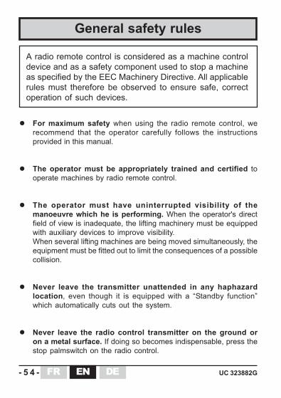
For maximum safety when using the radio remote control, werecommend that the operator carefully follows the instructionsprovided in this manual.
The operator must be appropriately trained and certified tooperate machines by radio remote control.
The operator must have uninterrupted visibility of themanoeuvre which he is performing. When the operator's directfield of view is inadequate, the lifting machinery must be equippedwith auxiliary devices to improve visibility.When several lifting machines are being moved simultaneously, theequipment must be fitted out to limit the consequences of a possiblecollision.
Never leave the transmitter unattended in any haphazardlocation, even though it is equipped with a “Standby function”which automatically cuts out the system.
Never leave the radio control transmitter on the ground oron a metal surface. If doing so becomes indispensable, press thestop palmswitch on the radio control.
General safety rules
A radio remote control is considered as a machine controldevice and as a safety component used to stop a machineas specified by the EEC Machinery Directive. All applicablerules must therefore be observed to ensure safe, correctoperation of such devices.
DEUC 323882G -55-EN FR
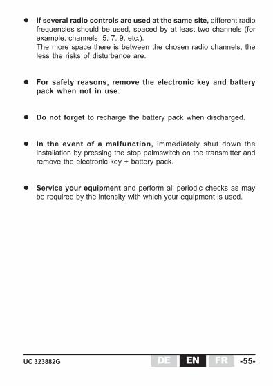
If several radio controls are used at the same site, different radiofrequencies should be used, spaced by at least two channels (forexample, channels 5, 7, 9, etc.).The more space there is between the chosen radio channels, theless the risks of disturbance are.
For safety reasons, remove the electronic key and batterypack when not in use.
Do not forget to recharge the battery pack when discharged.
In the event of a malfunction, immediately shut down theinstallation by pressing the stop palmswitch on the transmitter andremove the electronic key + battery pack.
Service your equipment and perform all periodic checks as maybe required by the intensity with which your equipment is used.

DE- 5 6 - UC 323882GENFR
With the UC radio remote controls, Jay Electronique provides solutionsto the broad range of standard industrial lifting applications.
Besides, a special attention has been given to ensure operator comfortthrough the following features :
Ergonomic transmitter enabling one-hand control Control button accessibility Button touch sensitivity Identification of functions controlled Light-weight transmitter Transmitter endurance, and fast, easy to replace plug-in battery pack Adaptability to all radio configurations of the environment by possibility
for changing frequency by a trained operator Mechanical protection of function buttons to avoid any unintentional action Transmitter carrying strap which hooks onto belt when unit is idle, or
removable shoulder strap (optional accessories)
1- Description of UC radio remote control
TTTTThank yhank yhank yhank yhank you fou fou fou fou for cor cor cor cor choosing our UC rhoosing our UC rhoosing our UC rhoosing our UC rhoosing our UC radioadioadioadioadiorrrrremote contremote contremote contremote contremote control system !ol system !ol system !ol system !ol system !
The UC radio remote control is designed for radio remotecontrol applications on lifting machines such as winches andhoists and for all remote control applications for machinespreviously controlled by a wired system or a control panel.The radio remote control enables the operator to better focuson his work as it allows him to choose his observation positionwhich is only limited by safety considerations (example: noone should be standing under a load).The radio remote control completes and enhances the classicsafety circuits (emergency stop circuits).
DEUC 323882G -57-EN FR
For any recommendations or questions concerning installationof the UC remote control system, contact us at our customerservice department :
Tel : +33.(0)4.76.41.44.55
Fax: +33.(0)4.76.41.44.44
To further enhance safety when using this equipment, technical solutionsand innovative options are also proposed :
Access is enabled by electronic key
The receiver is also very easy to install :
Compact receiver Spring-type connection terminals
Easy maintenance :
Customization entirely stored in electronic key Diagnostic aid indicator lights Fast repair by insertion of electronic key in an auxiliary transmitter
These radio remote controls fully satisfy the safety requirements of thecurrent applicable and draft standards and comply with the followingEuropean directives:
Machinery Directive : shutdown category 3 per EN954-1 RTTE : microwave equipment and telecommunication terminals (low
voltage, electromagnetic compatibility, radio-electric spectrum)

DE- 5 8 - UC 323882GENFR
n°1 n°2
n°7 n°8
électronique
n°5 n°6
n°3 n°4
électronique F 38330 Montbonnot-St-Martin
Ref : UCE . . . . . . Freq : 433,050 .. 434,790MHz
IP65Serie : ..../....Date : .. / ..
électronique F 38330 Montbonnot-St-Martin
Ref : UCR . . . . . - . . . Code : . . . .Freq : 433,050 .. 434,790MHz
Date : .. / ..Serie : ......./....Alim : ...V..
IP65
électronique
n°1 n°2
n°5 n°6
n°3 n°4
UP
DOWN
EVERSE
R ORWARD
F
NORTH
SOUTH
WEST
EAST
NORD
SUD
OUEST
EST
LEFT
RIGHT
•
12
•
1
•
12
12
3
34
3+4
121+2
1 2 3GA TE
ON
O F F
SHUNT
+RPM
-RPM
12
1+2
4
7 8 9
4 5 6
•
2
•
3
•
34
43
•
3+4
3
UCCU (110-230VAC / 5VDC withEuropean and English plugs)
UCR receiver
The UC comprises :
1.1- Unpacking the products
A radio transmitter : the UCE A radio receiver - the UCR - which decodes the information generated by the
remote control and controls movements of the machines. An electronic key for the transmitter wich enable receiver and transmitter
association. A plug-in battery pack : the UWB A battery pack charger : the UCCU
UCE transmitter
When unpacking the products, be sure to put the battery pack in load for 7hours minimum before a first use.
Technical manual
Electronic key(yellow colour)
Battery pack charger
Descriptive label of thereceiver
Buttonlabels
Descriptive label of thetransmitter
BatterypackUWB
«6+2» buttons or «8+2» buttonsHousing models
DEUC 323882G -59-EN FR
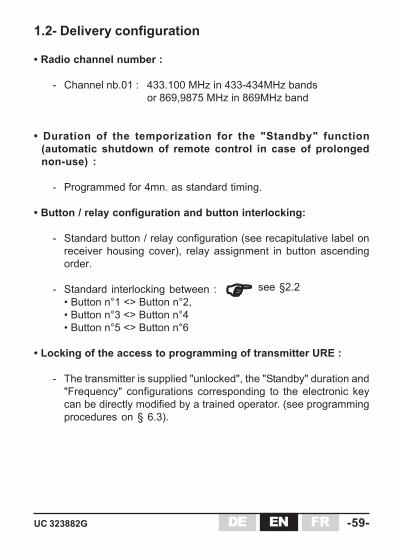
1.2- Delivery configuration
• Radio channel number :
- Channel nb.01 : 433.100 MHz in 433-434MHz bandsor 869,9875 MHz in 869MHz band
• Duration of the temporization for the "Standby" function(automatic shutdown of remote control in case of prolongednon-use) :
- Programmed for 4mn. as standard timing.
• Button / relay configuration and button interlocking:
- Standard button / relay configuration (see recapitulative label onreceiver housing cover), relay assignment in button ascendingorder.
- Standard interlocking between :• Button n°1 <> Button n°2,• Button n°3 <> Button n°4• Button n°5 <> Button n°6
• Locking of the access to programming of transmitter URE :
- The transmitter is supplied "unlocked", the "Standby" duration and"Frequency" configurations corresponding to the electronic keycan be directly modified by a trained operator. (see programmingprocedures on § 6.3).
see §2.2

DE- 6 0 - UC 323882GENFR
1st button of interlocked pair
2nd button of interlocked pair Abbreviation
Button n°5 Button n°6 B5-B6
Button n°3 Button n°4 B3-B4
Button n°1 Button n°2 B1-B2
2.2- Function button interlockingThe following function button interlocking configurations are possible:
6 two-step pushbuttons (double speed)+ 1 «On/Horn» button+ 1 stop palmswitch button
or8 two-step pushbuttons (double speed)+ 1 «On/Horn» button+ 1 stop palmswitch button
or6 two-step pushbuttons (double speed)+ 1 one-step pushbutton (single speed)+ 1 electronic switch with 3 positions+ 1 «On/Horn» button+ 1 stop palmswitch button
2- Type and specification of function buttonson UCE transmitter
2.1- Type and number of buttons
n°1 n°2
n°3 n°4
n°5 n°6
The transmitters come in 3 versions :
For each of the indicated interlocked pair, simultaneous action on thetwo buttons deactivates the commands (corresponding relays set to OFF).
(UCE front view)

DEUC 323882G -61-EN FR
On 9+3(1) relays receiver version :
Each two-step pushbuttons (BPDV - double speed) pair is assigned3 control relays (2 movement relays and a third relay for highspeed), the relay controlling the 2nd speed is thus common.
On 12+3(1) relays receiver version :
Each two-step pushbuttons (BPDV - double speed) pair is assigned4 control relays (2 movement relays and 1 relay for each highspeed), the relay controlling the 2nd speed is thus separated.
2.3- Correspondence between function buttons andrelays
A recapitulative label of these correspondences is sticked onUCR receiver housing cover.
For the transmitter referred UCE•222D0, the one-step pushbutton(BPSV - simple speed) control 1 relay while the electronic switchwith 3 positions (BPTR) control 2 relays (1/1+2/2).
See wiring examples for standard units in appendices D and E
(1) = 2 safety relays (RS1 et RS2) + 1 «Horn» relay (RK)

DE- 6 2 - UC 323882GENFR
Button configuration description Transmitter reference
Transmitter UCE with : 8 two-step pushbuttons (double speed) + 1 "On/Horn" button + 1 stop palmswitch button
delivered with : 1 battery pack (ref. UWB ) + 1 label kit "movements" (ref. UWE207 )
UCE222220 (433-434MHz)
UCEC22220 (869MHz)
Button configuration description Transmitter reference
UCE2222D0 (433-434MHz)
UCEC222D0 (869MHz)Transmitter UCE with : 6 two-step pushbuttons (double speed) + 1 one-step pushbutton (single speed) + 1 electronic switch with 3 positions + 1 "On/Horn" button + 1 stop palmswitch button
delivered with : 1 battery pack (ref. UWB ) + 1 label kit "movements" (ref. UWE207 )
Button configuration description Transmitter reference
UCE22220 (433-434MHz)
UCEC2220 (869MHz)Transmitter UCE with : 6 two-step pushbuttons (double speed). + 1 "On/Horn" button + 1 stop palmswitch button
delivered with : 1 battery pack (ref. UWB ) + 1 label kit "movements" (ref. UWE207 )
3- Product identification and matchingtransmitters / receivers
3.1- UCE transmittersTransmitters are delivered with a single battery pack (a second can be orderedseparately with the reference: UWB) and without electronic key, this one beingdelivered with the receiver (or can be ordered separately with the referenceUCWE22X).
électronique
électronique
électronique
DEUC 323882G -63-EN FR
48 - 115 VAC 48 - 230 VAC
433-434 MHz UCR0BL1 UCR0BM1869 MHz UCRABL1 UCRABM1
Number of relays
Power supply
With common second speed relay for two-step pushbuttons
+ 1 relay for the one-step pushbutton+ 2 relays (1/1+2/2) for the electronic
switch with 3 positions
12+3 (1) relays
Receiver reference
Relay configuration description
48 - 115 VAC 48 - 230 VAC 48 - 115 VAC 48 - 230 VAC
433-434 MHz UCR0BL0 UCR0BM0 UCR0AL0 UCR0AM0869 MHz UCRABL0 UCRABM0 UCRAAL0 UCRAAM0
12+3 (1) relays
Relay configuration description
9+3 (1) relays
With dedicated second speed relay for two-step pushbuttons
With common second speed relay for two-step pushbuttons
Number of relays
Power supply
Receiver reference
48 - 115 VAC 48 - 230 VAC
433-434 MHz UCR0BL2 UCR0BM2869 MHz UCRABL2 UCRABM2
12+3 (1) relays
With common second speed relay for two-step pushbuttons
UCRAB42UCR0B42
24 VDC
Receiver reference
Relay configuration description
Number of relays
Power supply
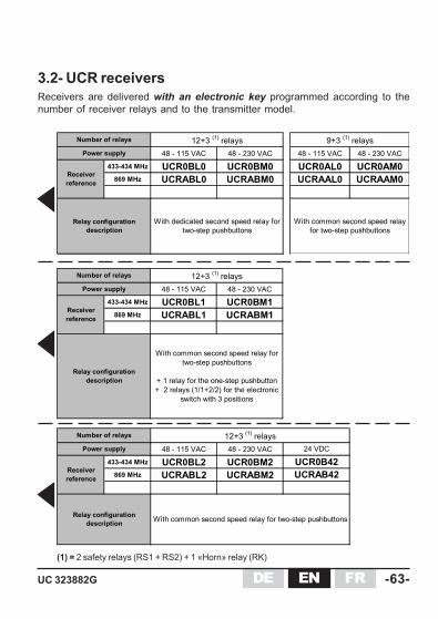
3.2- UCR receiversReceivers are delivered with an electronic key programmed according to thenumber of receiver relays and to the transmitter model.
(1) = 2 safety relays (RS1 + RS2) + 1 «Horn» relay (RK)
DE- 6 4 - UC 323882GENFR
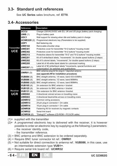
3.3- Standard unit referencesSee UC Series sales brochure, ref: E770.
3.4- AccessoriesReference Description
UCCU Charger 230VAC/5VDC with EU, UK and US plugs (battery pack charging)
UWB (1) Plug-in battery pack
UDC1 Wall support for stowing when idle and battery pack in charge
UCWE22X (2) Programmed electronic key (Parameters to be supplied)
UDP1 Belt fastening clip
UWE102 Removable shoulder strap
UWE301 Protective cover for transmitter "6+2 buttons" housing model
UWE302 Protective cover for transmitter "8+2 buttons" housing model
UWE313 Protective sleeve for transmitter "8+2" and "6+2 buttons" housing models
UWE201 Kit of 6 white/black labels, "movements", for double speed buttons (2 steps)
UWE202 Kit of 6 colored labels, "movements", for double speed buttons (2 steps)
UWE205 Label kit of 48 white blank labels for cutomized marking
UWE207 (1)Label kit of 90 white/black labels "movements, special functions and
customization" for switches and pushbuttons
OWR01 (3)BNC antenna plug kit for plug-in / deported antenna
(see appendix H for installation procedure)
VUB084 (4) BNC straight antenna, 1/4 wave, band 433-434MHz
VUB086 (4) BNC straight antenna, 1/2 wave, band 869MHz
VUB060 (4)(5) BNC straight antenna, 1/2 wave, band 869MHz
VUB105 (4) 2m extension for BNC antenna + bracket
VUB125 (4) 5m extension for BNC antenna + bracket
VUB131 (4) 10m extension for BNC antenna +bracket
UWE002 4 directional colored arrows on travelling crane
UWE003 4 directional black/white arrows on travelling crane
UDWR12 Common wiring accessory
UDWR13 24-pin plug-in connector + 2m cable
UDWR14 16-pin plug-in connector + 2m cable
UDWR38 Fastening Kit for receivers by magnetic contacts
UCWR32 Serial link board
UCWR36 (6) "DialogUC" software (CD-ROM + PC/UCR cable)
Transmitter
UCE
Receiver
UCR
(1)= supplied with the transmitter(2)= A programmed electronic key is delivered with the receiver, it is however
possible to order an electronic key by supplying us the following 2 parameters:- the receiver identity code,- the transmitter reference.
(3) = BNC antenna and BNC extension to be ordered separately.(4) = Require BNC tuner connector kit ref.: OWR01(5) = Not suitable for direct connection to antenna ref.: VUB086, in this case, use
an intermediate extension type VUB1••.(6) = Require serial link board ref.: UCWR32

DEUC 323882G -65-EN FR
Material ABS choc, yellowMechanical button protection
Tightness IP65
Complies with ETS 300 220Carrier UHF frequency modulated (FM)
<10 mW (license not required) in 433-434MHz or 869MHz
64 programmable frequencies in UHF 433-434 MHz bands or 12 programmable frequencies in UHF 869 MHz band
Average range (1) 100 m in typical industrial environment300 m in unobstructed area
Power supply Through plug-in NiMH battery pack (ref.: UWB)
433-434MHz bands 24 H 869MHz band 20 H
Operating temperature range -20°C to +50°CStorage temperature range(without battery pack) -30°C to +70°C
Storage temperature range(with battery pack) -30°C to +35°C
Attachment when idle Wall-mounted by wall support (ref.: UDC1) or on belt by fastening clip (ref.: UDP1)
Dimensions "6+2 buttons" housing model : 70x53x220 mm"8+2 buttons" housing model : 70x53x245 mm
Weight(with battery pack)
"6+2 buttons" housing model : 380 g"8+2 buttons" housing model : 450 g
"Dead man" function Time user-programmable (01 to 98mn or infinite)
Indiscations 1red indicator light "battery level" and "diagnostic"1 green indicator light "On" and "diagnostic"
Misc.
Transmit radio frequency(see list in appendix)
Endurance (at 50% transmit time for a typical use of function buttons)
Housing
Radio
Power supply and endurance
Temperature ranges
Transmit power(built-in antenna)
4- Technical characteristics
4.1- UCE transmitter
(1) = The range varies according to environment conditions, the reception antenna and its position (therange is decreased in case of metal obstacles such as: metal frameworks, walls etc.)
électronique
électronique
électronique
«Standby»
Indications

DE- 6 6 - UC 323882GENFR
4.1.1- Identity codeThe transmitter and receiver are linked by a frequency and an identity code.A receiver can only recognise and execute commands generated by the associatedtransmitter (same identity code and frequency).
- The frequency can be programmed by the user (see §. 6.3.2)- The transmitter identity code is contained in the electronic key and in the transmitter
UCE. This code can be reprogrammed by a trained user (see §.6.3.4)- The receiver identity code is a unique, fixed code, programmed in factory.
Identity codes have 65536 different combinations.
4.1.2- Electronic keyThe electronic key used on the UC radio remote control system has a dual function:
- It enables start-up of the transmitter by limiting access to the remote control totrained and authorized persons only.
- It contains all the information required for operation of the product, including :
- the system identity code- the last frequency programmed *- the «standby» function duration *
* = reprogrammable by a trained operator, see § 6.3
- When the key is removed, it prevents unauthorized use of the transmitter andcuts off the power supply to the transmitter. For this reason, it should be removed(as battery pack) when the remote control is put away.
Preferably, the electronic key should be removed after pressing the stop palmswitchbutton. Removal of the key before the stop palmswitch button button is pressedwill result in a fault indication (2 flashes) and passive shutdown of the receiver.
If necessary, it can be used to stop the transmitter.
The transmitter cannot be started up without itselectronic key.

DEUC 323882G -67-EN FR
électronique
n°1 n°2
n°3 n°4
n°5 n°6
Identity code containedin electronic key
Identity code containedin transmitter UCE
The transmitter UCE also has an internal memory containing an identity code.
- If the identity code of the electronic key matches the identity code stored in theUCE, the transmitter can be started up.
- If the identity code of the electronic key and that of the UCE do not match, thetransmitter indicates the problem by its two indicator lights (3 flashes). In thiscase, perform the programming procedure described in § 6.3.4.
UCE can be started up provided :
UCE identity code=
Electronic key identity code
In the event of a transmitter failure :
You can recover the electronic key and connect it on a maintenance transmitter(with same button configuration - 3 rows of double speed pushbuttons).
To perform this operation, you must reprogram the key identity code in the newtransmitter UCE as described in the procedure in § 6.3.4.
If your electronic key is lost :
You can order another programmed electronic key (ref: UCWE22X) making sureto specify 2 parameters :
1) the receiver identity code (code on 4 digits, on receiver descriptive label).2) the UCE transmitter reference (on transmitter descriptive label).
IMPORTANT : Store the electronic key in a safe, identified location.

DE- 6 8 - UC 323882GENFR
4.1.3- «Standby» function
The «standby» safety function deactivates the remote control (radio transmissioncut off) when the transmitter function buttons have not been actuated for aduration of N minutes.
The N parameter is user-configurable and can take the values 01 to 98 minutes.
On delivery, the duration is defined for 4 minutes.
- If N value is configured to 99 minutes, the transmitter considers that thestandby duration is infinite (until the battery pack is entirely discharged)
Restarting the transmitter after the «Standby» function has been activated :
- Press the stop palmswitch button on the transmitter.- Unlock the stop palmswitch button on the transmitter.- Press the green «On/Horn» button.
Changing the «standby» duration: :
The standby duration N can be modified by a trained operator by performing theprocedure described in § 6.3.3.
NB: The duration is stored in the UCE transmitter electronic key.

DEUC 323882G -69-EN FR
Material ABS, grey - IP65
64 programmable UHF channels in 433-434 MHz bandsor 12 programmable UHF channels in 869 MHz band
433-434MHz bands 1/4 wave869MHz band 1/2 wave
Sensitivity Better than -100dBm
Power supply(depending on model)
• 48-115 VAC (-15% to +10%) reference : UCR••L•• 48-230 VAC (-15% to +10%) reference : UCR••M•• 24VDC (-20% to +20% ) reference : UCR••4•
Receiver consumption(with 2 safety relays + "Horn" relay and 5 control relays activated)
• 48 VAC : 550 mA• 115 VAC : 200 mA• 230 VAC : 70 mA• 24 VDC : 430 mA
Control (according to UCR model) 9 relays + 1 "Horn" relay or 12 relays + 1 "Horn" relaySafety 2 relays with linked and guided contactsMaximum number of relays simultaneously controllable 8 (comprising 2 safety relays and "Horn" relay)
Response times
Passive stop (1) : 1,15 s maxActive stop (2) : 0,16 s maxOn startup : 0,5 s maxOn control : 0,07 s max
Power supply 1 M16 cap (cable diameter Ø 5 to 7 mm) (3)Outputs 1 M32 plastic cable gland (cable diameter Ø 20 to 26 mm)
Operating temperature range -20°C to +50°CStorage temperature range -30°C to +70°CRated impulse voltage strength 6kV at 2000 m altitude
Protection class reinforced insulationPollution degree 2 internal, 3 external
Indicator lights
3 LEDs on receiver board :- 1 green LED : "Power On"- 1 red LED : "wrong identity code + diagnostic"- 1 green LED : "radio link established + diagnostic" (see detailed function on §6.4.1)
Dimensions 120x240x100 mm (without antenna)Weight 1,2 kg
Housing
Radio (Complies with l'ETS 300 220)
Power supply and consumption
Input / Ouput cable entry
Environment withstand characteristics
Miscellaneous
Functional characteristics
Antenna (can be unplugged as an accessory with ref : OWR01)
Reception frequency(see list in appendix)
4.2- UCR receiver
(1) = «Passive Stop» caused by loss of radio connection with the transmitter or complete discharge of thetransmitter battery pack.
(2) = «Active Stop» caused by action on the transmitter stop palmswitch button.(3) = The cap can be replaced by a plastic cable gland (standard PE) type PG M16 mounted in its place.
DE- 7 0 - UC 323882GENFR
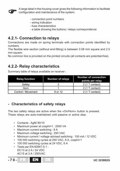
Relay function Number of relays Number of connection points per relay
Safety 2 2 (1 T contact)Horn 1 2 (1 T contact)
Control / Movement 9 or 12 2 (1 T contact)
A large label in the housing cover gives the following information to facilitateconfiguration and maintenance of the system:
- connection point numbers- wiring indication- fuse characteristics- a table showing the buttons / relays correspondence
4.2.1- Connection to relaysConnections are made on spring terminals with connection points identified bynumbers.The flexible wire section (without end-fitting) is between 0.08 mm square and 2.5mm square.No common line is provided on the printed circuits (all contacts are potential-free).
Summary table of relays available on receiver :
4.2.2- Relay characteristics
- Characteristics of safety relays
The two safety relays are active when the «On/Horn» button is pressed.These relays are auto-maintained until passive or active stop.
• Contacts : AgNi 90/10• Maximum power at cosphi=1 : 2000 VA• Maximum current switching : 8 A• Maximum voltage switching : 250 VAC• Minimum current / voltage advised switching : 100 mA / 12 VDC• 100 000 switching cycles at 250 VAC, 8 A, cosphi=1• 100 000 switching cycles at 24 VDC, 6 A• Tests per EN 60947-5-1 :
DC13 at 2 A / 24 VDCAC15 at 3 A / 250VAC

DEUC 323882G -71-EN FR
Safety relays
"Horn" relay and
"Control" relays
Switching at 230VAC (70VA,cosphi=0,75) 2 x 10⁶ 2 x 10⁶
Switching at 110VAC, (70VA,cosphi=0,75) 1 x 10⁶ 1 x 10⁶
Switching at 48VAC (70VA,cosphi=0,75) 0,5 x 10⁶ 0,5 x 10⁶
Number of switching cycles
Contactor Physical unit switched by relay
CA2DNLC1D09LC1D18LC2D09
- Characteristics of the «Horn» relay and «control» relays
• Contacts : AgNi 0,15• Maximum power at cosphi=1 : 2000 VA• Maximum current switching : 8 A• Maximum voltage switching : 400 VAC• Minimum current / voltage advised switching : 100 mA / 12 VDC• 100 000 switching cycles at 250 VAC, 8 A, cosphi=1• 50 000 switching cycles at 24 VDC, 8 A• Tests per EN 60947-5-1 :
DC13 à 0,5 A / 24 VDCAC15 à 3 A / 250VAC
The «Horn» relay is active when the transmitter «On/Horn» button is pressed.This relay isn’t auto-maintained.
«Control» relays are active when transmitter function buttons are pressed.
- Number of switching cycles on various contactors
DE- 7 2 - UC 323882GENFR
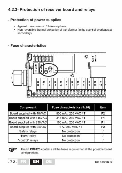
Component Fuse characteristics (5x20) Item
Board supplied with 48VAC 800 mA / 250 VAC / T F2Board supplied with 115VAC 315 mA / 250 VAC / T F1Board supplied with 230VAC 160 mA / 250 VAC / T F1Board supplied with 24VDC 1 A / 250 VAC / T F2
Safety relays No protection /"Horn" relay No protection /
"control" relays No protection /
R1
R1
R11
R10
R9
R8
R7
R6
R5
R4
R3
R2
RK
RS1
1
8
2345
9 10 11 12 13 14 15 16 17 18 19 20 21 22 23 24 25 26 27 28 29 30 31 32
F1F2
V1V2V3
67
RS2
• Against overcurrents : 1 fuse on phase.• Non-reversible thermal protection of transformer (in the event of overloads at
secondary).
4.2.3- Protection of receiver board and relays
- Protection of power supplies
- Fuse characteristics
The kit PR0123 contains all the fuses required for all the possible boardconfigurations.
DEUC 323882G -73-EN FR
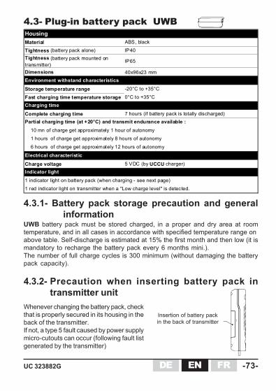
Material ABS, black
Tightness (battery pack alone) IP40Tightness (battery pack mounted on transmitter)
IP65
Dimensions 40x96x23 mm
Storage temperature range -20°C to +35°C
Fast charging time temperature storage 0°C to +35°C
Complete charging time 7 hours (if battery pack is totally discharged)
Charge voltage 5 VDC (by UCCU charger)
1 red indicator light on transmitter when a "Low charge level" is detected.
Partial charging time (at +20°C) and transmit endurance available :
Electrical characteristic
10 mn of charge get approximately 1 hour of autonomy1 hours of charge get approximately 8 hours of autonomy
6 hours of charge get approximately 12 hours of autonomy
1 indicator light on battery pack (when charging - see next page)
Housing
Environment withstand characteristics
Charging time
Indicator light
4.3- Plug-in battery pack UWB
4.3.1- Battery pack storage precaution and generalinformation
UWB battery pack must be stored charged, in a proper and dry area at roomtemperature, and in all cases in accordance with specified temperature range onabove table. Self-discharge is estimated at 15% the first month and then low (it ismandatory to recharge the battery pack every 6 months mini.).The number of full charge cycles is 300 minimum (without damaging the batterypack capacity).
4.3.2- Precaution when inserting battery pack intransmitter unit
Whenever changing the battery pack, checkthat is properly secured in its housing in theback of the transmitter.If not, a type 5 fault caused by power supplymicro-cutouts can occur (following fault listgenerated by the transmitter)
Insertion of battery packin the back of transmitter

DE- 7 4 - UC 323882GENFR
Indicator light on the transmitter:
Two battery charge status display functions are provided on the transmitter :
• When the remote control is powered up (stop palmswitch button out), the redindicator light on the transmitter shows the battery pack charge level :
Red indicator light off : ............................... Battery pack charge > 90%
Red indicator light flashes slowly : ............. Battery pack charge is between90% and 10 %
Red indicator light flashes quickly : ............ The battery pack must absolutelybe charged (battery pack charge< 10%)
• During operation of the remote control (radio transmission), a LOW BATT(battery low level, charge < 10%) indication is given by the red indicator lightwhich flashes quickly. This indication is used to inform the operator that theremote control will soon be unavailable (within around 15 minutes).
4.3.3- Display of battery pack charge state
Charging the battery :
During charging operation, indicator light of the battery pack comes on steadyand indicates the charge level :
The indicator light is orange : ....................... fast charge
The indicator light is green : ......................... slow and up-keep charge (UWBcharge > or = 60%)
The JAY Electronique charger UCCU is perfectly suited to charge the UWBbattery pack.
UWB
UCCU
DEUC 323882G -75-EN FR
5- Installation recommendations
Experience shows that the functional efficiency of the system basically depends onthe quality of the installation:
- Interference suppression,- Choice of operating frequency,- Marking of the controlled equipment,- Position of receiver and antenna,- Quality of wiring of receiver and associated systems,- Electrical power supply protection,- Minimum and maximum current of relay outputs.
5.1- Interference suppressionIn the event of inductive loads on the relay outputs (contactor coils, solenoid valvesor electro-brakes), interference suppression devices such as capacitors, RC circuits,diodes, etc. must be placed directly at the terminals of the controlled componentsusing the shortest possible connections.
5.2- Choice of operating radio frequencyThe 64 radio channels in 433-434MHz or 12 in 869MHz of the UC provide a broadrange of choices among the available frequencies. To ensure good operatingquality, it is important that the radio channel used be free throughout the area inwhich the machine will be controlled.
If several radio remote controls are operating on the same site, frequencies spacedby at least two radio channels (for example: 5, 7, 9 ...) should be used and, ifnecessary, a frequency plan should be drawn up, specifying the various machinescontrolled and their working frequency.
5.3- Marking of the controlled equipmentIf there are several equipment fitted with similar radio remote control systems workingin the same neighbourhood (e.g. in a plant), each transmitter shall carry a clearindication which tells the equipment driver which equipment is controlled by thetransmitter in question.

DE- 7 6 - UC 323882GENFR
The direction of movement of control buttons shall whenever possible be consistentwith equipment motion. Symbols shall be fixed in such positions that there is a clearand unambiguous relationship between the action on buttons in the control stationand the corresponding direction of motion.
The arrows are available in the following versions:
4-way black/white arrows, reference: UWE003
Signalling arrows are available as an accessory.Place the different arrows on the equipment to be controlled so that each arrowsymbol corresponds to that on the associated transmitter control button.
5.4- Receiver and antenna positionsThe remote control receiver UCR should be mounted as close as possible to thecontrol cabinet. The UCR receiver should be sheltered from shocks and weather.
The antenna must be installed at a distance from the class 3 cables and powercomponents (power supply, motor, variable speed drives …) while remaining inan area which is favourable to radio reception.
The receiver must be located at a height, above the operator using the transmitter,with the antenna directed downward.
No metal object which could form a screen should be located between theoperator and the antenna (risk of communication cut-out).
The antenna orientation is indicated in the figure below:
Unless a special connector such as the plug-in antenna adapter ref. OWR01(accessory) is used, the receiver antenna should not be modified.
Wrong
Good
UCR
Good
Good
met
al
met
al
met
al
met
al
490 mm
180mm
DEUC 323882G -77-EN FR
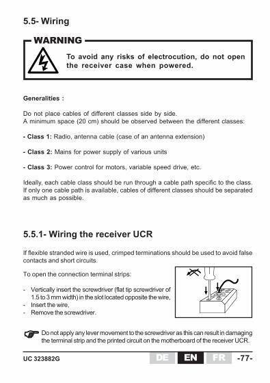
5.5- Wiring
5.5.1- Wiring the receiver UCR
Do not apply any lever movement to the screwdriver as this can result in damagingthe terminal strip and the printed circuit on the motherboard of the receiver UCR.
To open the connection terminal strips:
- Vertically insert the screwdriver (flat tip screwdriver of1.5 to 3 mm width) in the slot located opposite the wire,
- Insert the wire,- Remove the screwdriver.
If flexible stranded wire is used, crimped terminations should be used to avoid falsecontacts and short circuits.
Generalities :
Do not place cables of different classes side by side.A minimum space (20 cm) should be observed between the different classes:
- Class 1: Radio, antenna cable (case of an antenna extension)
- Class 2: Mains for power supply of various units
- Class 3: Power control for motors, variable speed drive, etc.
Ideally, each cable class should be run through a cable path specific to the class.If only one cable path is available, cables of different classes should be separatedas much as possible.
To avoid any risks of electrocution, do not openthe receiver case when powered.
WARNING
DE- 7 8 - UC 323882GENFR
R1
R8
R7
R6
R5
R4
R3
R2
RK
RS1
1
8
2345
9 10 11 12 13 14 15 16 17 18 19 20 21 22 23 24
F1F2
67
RS2
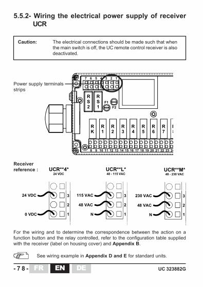
Caution: The electrical connections should be made such that whenthe main switch is off, the UC remote control receiver is alsodeactivated.
5.5.2- Wiring the electrical power supply of receiverUCR
Power supply terminalsstrips
For the wiring and to determine the correspondence between the action on afunction button and the relay controlled, refer to the configuration table suppliedwith the receiver (label on housing cover) and Appendix B.
See wiring example in Appendix D and E for standard units.
1
2
3115 VAC
48 VAC
N
UCR**L*48 - 115 VAC
1
2
3230 VAC
48 VAC
N
UCR**M*48 - 230 VAC
1
2
324 VDC
0 VDC
UCR**4*24 VDC
Receiverreference :
DEUC 323882G -79-EN FR
5.6- Electrical power supply protectionProtection against overcurrents (EN60204-1 § 7.2) resulting from overvoltages.A fuse or other protection device should be provided in the power supply circuit ofthe receiver (see wiring diagram for standard assemblies, item F in Appendix Dand E). The assigned current is defined in the table in § 4.2.3.
5.8- Auxiliary controlMeasures should be taken to ensure, that when the radio control is notin service, another control system can be used to ensure the safety ofthe operator and the manipulated load.
5.7- Minimum and maximum current of relay outputsBe sure not to exceed the minimum and maximum characteristics specified in §4.2.2 by installing, if necessary, an additional load or intermediate relays (auxiliarycontacts in electrical cabinet for power control, for example).
DE- 8 0 - UC 323882GENFR
6- Commissioning and operation
6.1- Precautions when commissioning
• On reception of the product, charge the battery pack for 7 hours.
• The installer must :
- ensure that the electronic key corresponds with the receiver,- ensure that transmitter and receiver have the same radio channel,- ensure that the radio channel chosen corresponds to the frequency plan set
up for the site,- perform a final check to verify that the desired Button-Relay correspondence
is in place.
• During the previous check, the installer must check that when the «On/Horn»button is pressed on startup, only safety relays are activated.
• Verify the priority general shutdown mode (remote control in operation) :
Active stop : When the stop palmswitch button on the transmitter ispressed, receiver safety relays should instantaneouslychange state.
Passive stop : When the electronic key is removed from the transmitter inoperation, receiver safety relays should change state withintwo seconds max.
• «Standby» function duration :Check the effective duration of the "Standby" function (automatic shutdown oftransmitter) :Start up the remote control and leave it without activating any control. Record thetime after which the receiver safety relays are deenergized and check that thisduration corresponds to the standard duration supplied (4min.) or to the newduration defined by a trained and authorized operator in accordance with theprocedure described in § 6.3.3.
• Radio range limits :In transmit mode, evaluate the range limit between transmitter and receiver (bymoving up to the range limit).
DEUC 323882G -81-EN FR
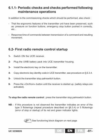
6.2- First radio remote control startup
1- Switch ON the UCR receiver.
2- Plug the UWB battery pack into UCE transmitter housing.
3- Install the electronic key on the transmitter.
4- Copy electronic key identity code in UCE transmitter, see procedure on § 6.3.4.
5- Unlock the transmitter stop palmswitch button.
6- Press the «On/Horn» button until the receiver is started up. (safety relays areactivated).
6.1.1- Periodic checks and checks performed followingmaintenance operations
In addition to the commissioning checks which should be performed, also check :
- That the ergonomic features of the transmitter unit have been preserved, suchas: pressure on function buttons, emergency stop button pushed in correctly,etc...
- Response time of commands between transmission of a command and resultingmovement.
See functioning block diagram on next page
NB : If this procedure is not observed the transmitter indicates an error of thetype 3 flickerings (repeat procedure described on §6.3.4) or 5 flickerings(error of stop or startup) of its red and green indicator lights.
To stop the radio remote control : press the transmitter stop palmswitch button.

DE- 8 2 - UC 323882GENFR
T
Red
sto
p pa
lmsw
itch
unlo
cked
,U
CE
trans
mitt
erpo
wer
ed u
p
Gre
en"O
n/H
orn"
butto
n pr
esse
d
Pass
ive
stop
if "
Stan
dby"
dura
tion
is e
xcee
ded
(1)
or Bat
tery
pac
k is
disc
onne
cted
/dis
char
ged
(2)
or Elec
tron
ic k
ey re
mov
ed fr
omU
CE
in o
pera
tion
OFF
Stan
dby
Activ
e
3 st
ates
of U
CE
UC
R s
afet
yre
lays
UC
E gr
een
indi
cato
r lig
ht
3 st
ates
of r
edin
dica
tor l
ight
of U
CE
(bat
tery
pac
k ch
arge
st
ate)
Activ
e st
op b
y pr
essi
ngst
op p
alm
switc
h bu
tton
Or
Last
act
ion
onfu
nctio
n pu
shbu
tton
(1) "
Stan
dby"
dur
atio
n
Pass
ive
stop
: b
atte
ry p
ack
is d
isch
arge
d
UTI
LISA
TIO
N
(2)
Batte
ry p
ack
char
ge >
90
%
90%
> B
atte
ry p
ack
char
ge >
10%
Batte
ry p
ack
char
ge <
10%
90%
> C
harg
e >
10 %
Cha
rge
< 10
%
Cha
rge
< 10
%
6.2.1- Functioning block diagram
DEUC 323882G -83-EN FR
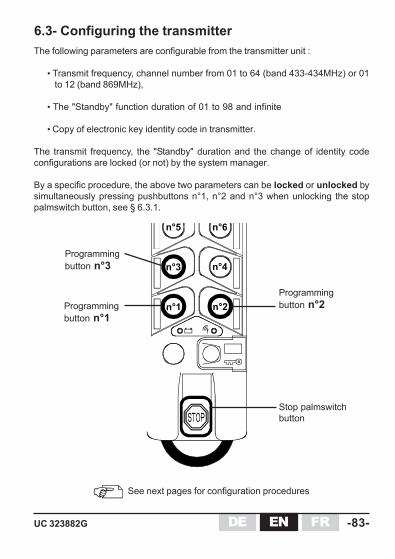
The following parameters are configurable from the transmitter unit :
• Transmit frequency, channel number from 01 to 64 (band 433-434MHz) or 01to 12 (band 869MHz),
• The "Standby" function duration of 01 to 98 and infinite
• Copy of electronic key identity code in transmitter.
The transmit frequency, the "Standby" duration and the change of identity codeconfigurations are locked (or not) by the system manager.
By a specific procedure, the above two parameters can be locked or unlocked bysimultaneously pressing pushbuttons n°1, n°2 and n°3 when unlocking the stoppalmswitch button, see § 6.3.1.
6.3- Configuring the transmitter
See next pages for configuration procedures
n°1 n°2
n°5 n°6
n°3 n°4
Programmingbutton n°1
Programmingbutton n°2
Stop palmswitchbutton
Programmingbutton n°3

DE- 8 4 - UC 323882GENFR
n°1 n°2
n°3 n°4
n°1 n°2
n°3 n°4
n°1 n°2
n°3 n°4
n°1 n°2
6.3.1 Procedure: "Locking-unlocking" access toprogramming of transmitter UCE
1- Switch off the receiver.2- Insert the electronic key in the transmitter unit.3- Holding buttons n°1, n°2 and n°3 pressed, unlock the stop palmswitch button
(fig.1).4- Release the buttons.
Indicator lights statuses:- transmitter locked : red indicator light on, green indicator light off.- transmitter unlocked : red and green indicator lights on.
5- Select «locked» or «unlocked» by pressing button n°2; the selected mode isshown by the indicator lights (fig.2&3).
6- Validate the selected mode by pressing the "On/Horn" button (fig.4).7- The transmitter saves the new mode in the electronic key and switches off the
indicator lights.8- Exit the "locking - unlocking" configuration mode by pressing the stop palmswitch
button (fig.6).
Remark: If an operator attempts to program the frequency, the "Standby"function duration or identity code with the transmitter locked, thetransmitter will indicate an error by its indicator lights which will flashin alternation.
Locking Unlocking
n°1 n°2
n°3 n°4
DATA
Electronickey
memory
Fig.1 Fig.2 Fig.3
Fig.4 Fig.5 Fig.6
DEUC 323882G -85-EN FR
n°1 n°2
n°3 n°4
n°5 n°6 DATA
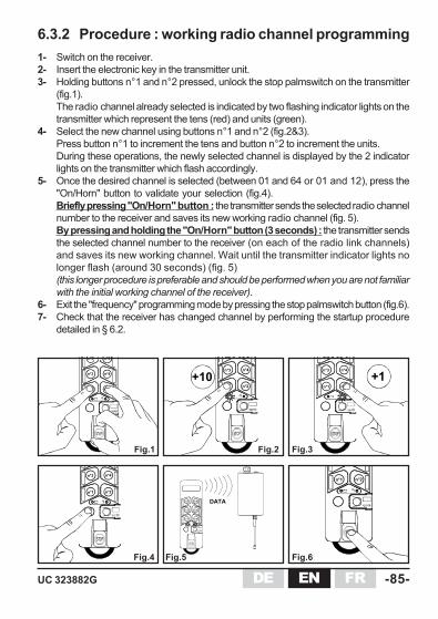
6.3.2 Procedure : working radio channel programming1- Switch on the receiver.2- Insert the electronic key in the transmitter unit.3- Holding buttons n°1 and n°2 pressed, unlock the stop palmswitch on the transmitter
(fig.1).The radio channel already selected is indicated by two flashing indicator lights on thetransmitter which represent the tens (red) and units (green).
4- Select the new channel using buttons n°1 and n°2 (fig.2&3).Press button n°1 to increment the tens and button n°2 to increment the units.During these operations, the newly selected channel is displayed by the 2 indicatorlights on the transmitter which flash accordingly.
5- Once the desired channel is selected (between 01 and 64 or 01 and 12), press the"On/Horn" button to validate your selection (fig.4).Briefly pressing "On/Horn" button : the transmitter sends the selected radio channelnumber to the receiver and saves its new working radio channel (fig. 5).By pressing and holding the "On/Horn" button (3 seconds) : the transmitter sendsthe selected channel number to the receiver (on each of the radio link channels)and saves its new working channel. Wait until the transmitter indicator lights nolonger flash (around 30 seconds) (fig. 5)(this longer procedure is preferable and should be performed when you are not familiarwith the initial working channel of the receiver).
6- Exit the "frequency" programming mode by pressing the stop palmswitch button (fig.6).7- Check that the receiver has changed channel by performing the startup procedure
detailed in § 6.2.
n°1 n°2
n°1 n°2
n°3 n°4
n°1 n°2
n°3 n°4
+1n°1 n°2
n°3 n°4
+10n°1 n°2
n°3 n°4
n°5 n°6
Fig.1 Fig.2 Fig.3
Fig.4 Fig.5 Fig.6

DE- 8 6 - UC 323882GENFR
n°1 n°2
n°3 n°4 +1mn
n°1 n°2
n°3 n°4+10mn
n°1 n°2
n°3 n°4
n°5 n°6
6.3.3 Procedure : "Standby" function timeprogramming(Automatic shutdown of transmitter)
1- Switch off the receiver.2- Insert the electronic key in the transmitter unit.3- Holding buttons n°1 and n°3 pressed, unlock the stop palmswitch button on the
transmitter (fig.1).The "Standby" time is displayed by two flashing indicator lights on the transmitterrepresenting the tens (red) and the units (green) of the number of minutes.
4- Select the new time using buttons n°1 and n°2 (fig.2&3).Press button n°1 to increment the tens and button n°2 to increment the units.During these operations, the new time selected is displayed by the two indicatorlights on the transmitter.
5- Once you have selected the desired "Standby" time (between 01 and 99),press the «On/Horn» button to validate your selection (fig.4).
Caution: No. 99 corresponds to an infinite "Standby" time> This function is then deactivated and forgetting that the transmitter isstopped (by pressing the stop palmswitch button) will result in completedischarge of the transmitter..
6- Exit the "Standby" time programming mode by pressing the stop palmswitchbutton (fig.6).
n°1 n°2
n°1 n°2
n°3 n°4
Fig.1 Fig.2 Fig.3
Fig.4 Fig.6
DATA
Electronickey
memoryFig.5

DEUC 323882G -87-EN FR
n°1 n°2
n°3 n°4
n°5 n°6
Reminder :To use the UC radio remote control system, the identity code contained in thetransmitter memory must match the identity code in the electronic key which is itselfidentical to that of the receiver.
If a maintenance transmitter is used or if you change electronic key, the informationcontained in the electronic key must be copied in the memory of the transmitter UCE.
Conditions for using this procedure :The configuration of the backup transmitter buttons must be identical to that describedin the electronic key (or the original transmitter).
6.3.4 Procedure: "Copying electronic key identity codein transmitter UCE"
1- Switch off the receiver2- Insert the electronic key in the transmitter unit.3- While holding buttons B2 and B3 pressed, unlock the transmitter emergency
stop button (fig. 1): the 2 indicator lights on the transmitter UCE will flashrapidly.
4- Press the "On/Horn" button to perform automatic programming of the identitycode: the two indicator lights on the transmitter UCE go off (fig. 2).
5- The "identity code" information is copied from the electronic key to the transmittermemory (fig. 3).
6- Exit the programming mode by pressing the stop palmswitch button (fig.4).
Apply this procedure when using a maintenance transmitter orwhen changing electronic key
n°1 n°2
n°3 n°4
n 5 n 6
DATA
n°1 n°2
n°3 n°4
n°5 n°6
Fig.3Fig.1 Fig.2 Fig.4
Mémoireclé
MémoireUCE
The working frequency may need to be programmed (for example, if thenew electronic key is programmed on another frequency), Perform then theprocedure described on § 6.3.2.
DE- 8 8 - UC 323882GENFR
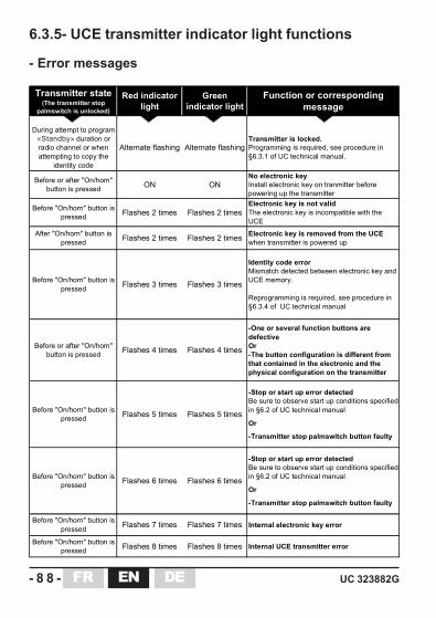
Transmitter state(The transmitter stop
palmswitch is unlocked)
Red indicator light
Green indicator light
Function or corresponding message
During attempt to program "Dead man" duration or radio channel or when attempting to copy the
identity code
Alternate flashing Alternate flashingTransmitter is locked.Programming is required, see procedure in §6.3.1 of UC technical manual.
Before or after "On/horn" button is pressed ON ON
No electronic keyInstall electronic key on tranmitter before powering up the transmitter
Before "On/horn" button is pressed Flashes 2 times Flashes 2 times
Electronic key is not validThe electronic key is incompatible with the UCE
After "On/horn" button is pressed Flashes 2 times Flashes 2 times Electronic key is removed from the UCE
when transmitter is powered up
Before "On/horn" button is pressed Flashes 3 times Flashes 3 times
Identity code errorMismatch detected between electronic key and UCE memory.
Reprogramming is required, see procedure in §6.3.4 of UC technical manual
Before or after "On/horn" button is pressed Flashes 4 times Flashes 4 times
-One or several function buttons are defectiveOr-The button configuration is different from that contained in the electronic and the physical configuration on the transmitter
Before "On/horn" button is pressed Flashes 5 times Flashes 5 times
-Stop or start up error detectedBe sure to observe start up conditions specified in §6.2 of UC technical manual
Or
-Transmitter stop palmswitch button faulty
Before "On/horn" button is pressed Flashes 6 times Flashes 6 times
-Stop or start up error detectedBe sure to observe start up conditions specified in §6.2 of UC technical manual
Or
-Transmitter stop palmswitch button faulty
Before "On/horn" button is pressed Flashes 7 times Flashes 7 times Internal electronic key error
Before "On/horn" button is pressed Flashes 8 times Flashes 8 times Internal UCE transmitter error
6.3.5- UCE transmitter indicator light functions
- Error messages
«Standby»

DEUC 323882G -89-EN FR
Transmitter state(stop palmswitch button
unlocked)
Red indicator light
Green indicator light
Function or corresponding message
Programming mode :"Dead man" time or radio
frequency
Flashes according to number of tens
of parameter configured
Flashes according to number of units
of parameter configured
Indicates tens or units
Procedure :Locking - unlocking
access to programmingON OFF Transmitter is locked
Procedure :Locking - unlocking
access to programmingON ON Transmitter is unlocked
Transmitter state(stop palmswitch button
unlocked)
Red indicator light
Green indicator light
Function or corresponding message
Before or after "On/horn" button is pressed OFF OFF
Shut down or"Dead man" time exceeded or
battery pack discharged
Before "On/horn" button is pressed OFF ON Battery pack charge > 90%
Before "On/horn" button is pressed Flashes SLOW ON 90% > Battery pack charge > 10%
Before "On/horn" button is pressed Flashes FAST ON Battery pack charge < 10 %
After "On/horn" button is pressed OFF Flashes SLOW Radio transmission
Battery pack charge > 10%
After "On/horn" button is pressed Flashes FAST Flashes SLOW Radio transmission
Battery pack charge < 10 %
- Battery pack charge level
- Messages during the programming of the UCE (cf.§6.3)
«Standby»
«Standby»

DE- 9 0 - UC 323882GENFR
6.4- Configuring the UCR receiverReceiver parameters :
• Button interlocking :Factory-configured, cannot be changed by user.
• Button/function relay correspondence :Factory-configured, cannot be changed by user.
• Radio reception frequency :Factory-configured on radio channel 01 (433,100MHz or 869,9875MHz), canbe programmed by a trained and authorized user :
- By transmitter paired to receiver, applying working radio channelprogramming procedure (see § 6.3.2).
6.4.1- UCR receiver indicator light functionsName and
color of LED
Mode Indication Message State
No message reception OFF
Poor radio reception Flashing
Good radio reception ON
Power supply error 2 flashes
"On" relay fault 3 flashes
EEPROM 4 flashes
RAM 5 flashes
ROM 6 flashes
Micro type 7 flashes
No message reception OFF
Message reception with
correct identity codeOFF
Message reception with
incorrect identity codeRegular flashes
Power supply error 2 flashes
"On" relay fault 3 flashes
EEPROM 4 flashes
RAM 5 flashes
ROM 6 flashes
Micro type 7 flashes
Receiver switched OFF OFF
Receiver switched ON ON
V1 ledpower supply
(Green)All
V2 led(Red)
V3 led(Green)
Indicates power
supply state
Receiver in
functioning
Indicates validity of
identity code
Indicates radio
reception quality
Indicates a fault
Indicates a fault
Receiver in
functioning
In case of fault
In case of fault
DEUC 323882G -91-EN FR
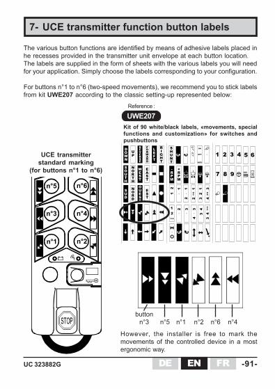
Kit of 90 white/black labels, «movements, specialfunctions and customization» for switches andpushbuttons
7- UCE transmitter function button labels
For buttons n°1 to n°6 (two-speed movements), we recommend you to stick labelsfrom kit UWE207 according to the classic setting-up represented below:
However, the installer is free to mark themovements of the controlled device in a mostergonomic way.
UCE transmitterstandard marking
(for buttons n°1 to n°6)
n°1 n°2
n°5 n°6
n°3 n°4
UWE207Reference :
UP
DOWN
EVERSE
RORWARD
F
NORTH
SOUTH
WEST
EAST
NORD
SUD
OUEST
EST
LEFT
RIGHT
•
12
•
1
•
12
12
3
34
3+4
12
1+2
1 2 3GATE
ON
OFF
SHUNT
+RPM
-RPM
12
1+2
4
7 8 9
4 5 6
•
2
•
3
•
34
43
•
3+4
3
n°6 n°4n°1 n°2button
n°3 n°5
The various button functions are identified by means of adhesive labels placed inhe recesses provided in the transmitter unit envelope at each button location.The labels are supplied in the form of sheets with the various labels you will needfor your application. Simply choose the labels corresponding to your configuration.
DE- 9 2 - UC 323882GENFR
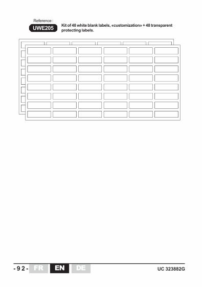
Kit of 48 white blank labels, «customization» + 48 transparentprotecting labels.UWE205
Reference :

DEUC 323882G -93-EN FR
8- Servicing
BEFORE STARTING ANY SERVICING OPERATION, SWITCHOFF THE MAIN POWER SUPPLY FOR THE SYSTEMCONTROLLED.
Servicing the UCE transmitter :
- Housing of the UCE transmitter must not be opened. The UCEcan be dismanteld only be a trained staff, in a "controlled"environment, spare parts can be changed only by identical parts.
- If one of the membranes of the function buttons or the seal ofthe transmitter is damaged, the UCE must not be any moreused until replacement of these tightness spare parts.In opposite case, any liquid, any dust or any foreign body candamage the transmitter.
- The attention of the user is attracted to the risks of the use of theremote control in an environment containing solvents of polymersor glues which can degrade the good functioning of transmiitermechanical organs.
- Verify regularly the good state of the transmitter, paying a specialattention on the function button membranes, on the electronic keyconnector and on the battery pack connector.
- Clean the transmitter by eliminating any foreign matter.Only use non aggressive cleaning product on base of soapysolution.
DE- 9 4 - UC 323882GENFR
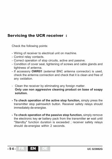
Check the following points:
- Wiring of receiver to electrical unit on machine.- Control relay contacts.- Correct operation of stop circuits, active and passive.- Condition of cover seal, tightening of screws and cable glands and
tightness of antenna.- If accessory OWR01 (external BNC antenna connector) is used,
check the antenna connection and check that it is clean and free ofany oxidation.
- Clean the receiver by eliminating any foreign matter.Only use non aggressive cleaning product on base of soapysolution.
- To check operation of the active stop function, simply press thetransmitter stop palmswitch button. Receiver safety relays shouldimmediately de-energise.
- To check operation of the passive stop function, simply removethe electronic key or battery pack from the transmitter or wait until"Standby" function duration is exceeded ; receiver safety relaysshould de-energise within 2 seconds.
Servicing the UCR receiver :

DEUC 323882G -95-EN FR
Reference Description
PR0123 ..................... Fuse kit
UCE transmitter
UCR receiver
List of parts which can be interchanged by user:
Accessibility to the replacement parts depends on the training level of the end user:
Level 1 : Replacement parts requiring no special tools or training
Level 2 : Replacement parts requiring a repair data package, special trainingand tools. These parts are only accessible to end users havingsuccessfully completed a level 2 training course.
The UC structure limits level 1 interventions for the end user.
The level 2 interventions are performed in a technical center approved byJAY Electronique
No spare part is accessible for this maintenance level.
9- Maintenance
DE- 9 6 - UC 323882GENFR
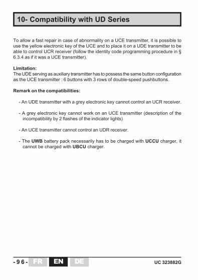
To allow a fast repair in case of abnormality on a UCE transmitter, it is possible touse the yellow electronic key of the UCE and to place it on a UDE transmitter to beable to control UCR receiver (follow the identity code programming procedure in §6.3.4 as if it was a UCE transmitter).
Limitation:The UDE serving as auxiliary transmitter has to possess the same button configurationas the UCE transmitter : 6 buttons with 3 rows of double-speed pushbuttons.
Remark on the compatibilities:
- An UDE transmitter with a grey electronic key cannot control an UCR receiver.
- A grey electronic key cannot work on an UCE transmitter (description of theincompatibility by 2 flashes of the indicator lights)
- An UCE transmitter cannot control an UDR receiver.
- The UWB battery pack necessarily has to be charged with UCCU charger, itcannot be charged with UBCU charger.
10- Compatibility with UD Series
DEUC 323882G -97-EN FR
11- WarrantyAll our devices are guarantied 2 years as of the date of manufacture indicatedon the product, wear parts not included. Repair, modification or replacementof a unit during the warranty period will not give rise to extension of the period.
Limits of warranty :
The warranty does not cover defects resulting from :
• transport• false manoeuver or non-observance of connection diagrams when setting
the equipment into service• insufficient supervision or servicing, utilization not complying with the
specifications detailed in the technical manual and, as a general rule, storage,operation or environment conditions (atmospheric, chemical, electrical or otherconditions).
• Conditions not specified on order of the equipment
The warranty shall not apply subsequent to any modifications or additions to theequipment performed by the customer without written approval by JAY Electronique.
The JAY Electronique responsability during the warranty period is limited to materialand construction defects. This warranty comprises repair in the JAY workshops orreplacement, free of charge, of parts recognized to be defective following expertinspection by the Jay Technical Department.
The warranty shall not give rise to any compensation for damage claims.
Any disputes relative to a supply or settlement thereof shall be ruled by the COURTOF COMMERCE OF GRENOBLE, solely competent, even in the event of an Appealor a plurality of defendants.

DE- 9 8 - UC 323882GENFR
UC 323882G -147-EN FRDE
• Annexes• Appendix• Anhang

-148- UC 323882GENFR DE
UC 323882G -149-EN FRDE
n°1 n°2
n°7 n°8
électronique
n°5 n°6
n°3 n°4
électronique
n°1 n°2
n°5 n°6
n°3 n°4
A
E
B
C
D
F
G
H
J
LM
K
i
N
Français
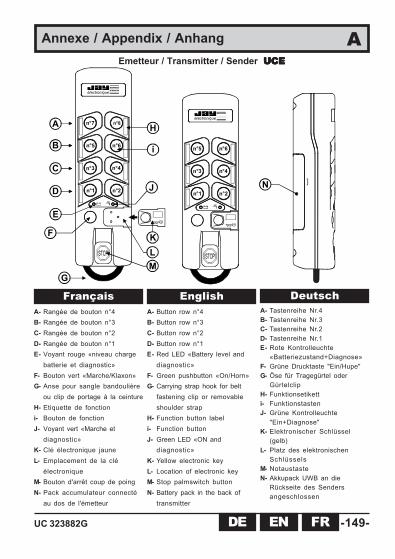
Annexe / Appendix / Anhang AEmetteur / Transmitter / Sender UCEUCEUCEUCEUCE
A- Rangée de bouton n°4B- Rangée de bouton n°3C- Rangée de bouton n°2D- Rangée de bouton n°1E- Voyant rouge «niveau charge
batterie et diagnostic»F- Bouton vert «Marche/Klaxon»G- Anse pour sangle bandoulière
ou clip de portage à la ceintureH- Etiquette de fonctioni- Bouton de fonctionJ- Voyant vert «Marche et
diagnostic»K- Clé électronique jauneL- Emplacement de la clé
électroniqueM- Bouton d'arrêt coup de poingN- Pack accumulateur connecté
au dos de l'émetteur
EnglishA- Button row n°4B- Button row n°3C- Button row n°2D- Button row n°1E- Red LED «Battery level and
diagnostic»F- Green pushbutton «On/Horn»G- Carrying strap hook for belt
fastening clip or removableshoulder strap
H- Function button labeli- Function buttonJ- Green LED «ON and
diagnostic»K- Yellow electronic keyL- Location of electronic keyM- Stop palmswitch buttonN- Battery pack in the back of
transmitter
DeutschA- Tastenreihe Nr.4B- Tastenreihe Nr.3C- Tastenreihe Nr.2D- Tastenreihe Nr.1E- Rote Kontrolleuchte
«Batteriezustand+Diagnose»F- Grüne Drucktaste "Ein/Hupe"G- Öse für Tragegürtel oder
GürtelclipH- Funktionsetiketti- FunktionstastenJ- Grüne Kontrolleuchte
"Ein+Diagnose"K- Elektronischer Schlüssel
(gelb)L- Platz des elektronischen
SchlüsselsM- NotaustasteN- Akkupack UWB an die
Rückseite des Sendersangeschlossen

-150- UC 323882GENFR DE
1
8
2345
F1
F2
V3
V2V1
RK
R1
R2
R3
R4
R5
R6
R7
R8
R9
R10
R11
R12
RS1910
13
16
1112
1415
19
1718
22
2021
25
2324
28
2627
31
2930
3332
A
B
C
D
E F
H
i
J
K
67RS2
L
G
MN
O
Annexe / Appendix / Anhang B 1/2
Récepteur / Receiver / Empfänger UCRUCRUCRUCRUCR
UC 323882G -151-EN FRDE
Français
Annexe / Appendix / Anhang B 2/2
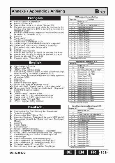
A- Presse étoupe "Commande"B- Relais "Klaxon" RKC- Bornier des contacts du relais "Klaxon" RKD- Borniers des contacts des relais de commande (le
nombre des borniers différe suivant la version durécepteur UCR)
E- Relais de commande (le nombre de relais différe suivantla version du récepteur UCR)
F- AntenneG- Tuner radioH - Voyants du récepteur :V1- Voyant vert "Alimentation UCR"V2- Voyant rouge "Code d'identité erroné + diagnostic"V3- Voyant vert "Liaison radio établie + diagnostic"i- Connecteur pour carte liaison sérieJ- FusiblesK- Bornier "Alimentation"L- Bornier des contacts du relais de sécurité n°1 RS1M- Bornier des contacts du relais de sécurité n°2 RS2N- Relais de sécurité RS1 et RS2O- Passage câble "Alimentation"
EnglishA- Cable gland «Control»B- «Horn» relay RKC- «Horn» relay terminal stripsD- Control relay terminal strips (number of terminal strips
differ according to version of receiver UCR)E- Control relays (number of relays differ according to version
of receiver UCR)F- AntennaG- Radio tunerH- Receiver indicator lights :V1- Green indic. light "UCR power supply"V2- Red indic. light "Wrong identity code + diagnostic"V3- Green indic. light "Radio link established + diagnostic"i- Serial link board connectorJ- FusesK- "Power supply" terminal stripsL- Safety relay nb.1 RS1 relay terminal stripsM- Safety relay nb.2 RS2 relay terminal stripsN- Safety relays RS1 and RS2O- «Power supply» cable passage
DeutschA- Stopfbuchse für Durchführung der SteuerkabelB- "Hup"-Relais (RK)C- Klemme des "Hup"-Relais (RK)D- Anschlussklemmen "Steuerung" (je nach UCR Modell)E- Steuerrelais (Anzahl der Relais nach dem Empfänger-
Modell)F- AntenneG- Tuner RadioH- Kontrolllampen :V1- Grüne : «Stromversorgung»V2- Rote : «Falscher Identitätscode + Diagnose»V3- Grüne : «Funkverbindung hergestellt und Diagnose»i- Steckverbindung für serielle VerbindungskarteJ- SicherungenK- Anschlussklemmen «Stromversorgung»L- Anschlußklemme für Sicherheitsrelais RS1M- Anschlußklemme für Sicherheitsrelais RS2N- Sicherheitsrelais RS1 und RS2O- Durchführung Versorgungskabel Empfänger
Ansch. Nr- Funktion1 Nulleiter oder 0 v *2 48VAC *3 230VAC oder 115VAC oder 24VDC *
4 - 5 Sicherheitsrelais Nr.1 (RS1)6 - 7 Sicherheitsrelais Nr.2 (RS2)8 - 9 "Hup"-Relais (RK)
10 - 11 Steuerrelais R112 - 13 Steuerrelais R214 - 15 Steuerrelais R316 - 17 Steuerrelais R418 - 19 Steuerrelais R520 - 21 Steuerrelais R622 - 23 Steuerrelais R724 - 25 Steuerrelais R826 - 27 Steuerrelais R928 - 29 Steuerrelais R10 *30 - 31 Steuerrelais R11 *32 - 33 Steuerrelais R12 *
Anschlussklemmen Empfänger UCR
* = je nach Empfängermodell
Borne N° Fonction1 Neutre ou 0 v *2 48 VAC *3 230 VAC ou 115 VAC ou 24 VDC *
4 - 5 Relais sécurité n°1 (RS1)6 - 7 Relais sécurité n°2 (RS2)8 - 9 Relais "Klaxon" (RK)
10 - 11 Relais de fonction R112 - 13 Relais de fonction R214 - 15 Relais de fonction R316 - 17 Relais de fonction R418 - 19 Relais de fonction R520 - 21 Relais de fonction R622 - 23 Relais de fonction R724 - 25 Relais de fonction R826 - 27 Relais de fonction R928 - 29 Relais de fonction R10 *30 - 31 Relais de fonction R11 *32 - 33 Relais de fonction R12 *
Borniers du récepteur UCR
* = suivant la version du récepteur
Term. Nb. Function1 Neutral or 0 v *2 48 VAC *3 230 VAC or 115 VAC or 24 VDC *
4 - 5 Safety relay nb.1 (RS1)6 - 7 Safety relay nb.2 (RS2)8 - 9 "Horn" relay (RK)
10 - 11 Function relay R112 - 13 Function relay R214 - 15 Function relay R316 - 17 Function relay R418 - 19 Function relay R520 - 21 Function relay R622 - 23 Function relay R724 - 25 Function relay R826 - 27 Function relay R928 - 29 Function relay R10*30 - 31 Function relay R11*32 - 33 Function relay R12*
UCR receiver terminal strips
* = depending on UCR version

-152- UC 323882GENFR DE
électronique
220
70 53
électronique
245
Annexe / Appendix / Anhang C 1/2
électronique
121 mm
35 mm 56 mm
22 m
m
Ø4 mm
200 mmmini
EmetteurTransmitterSenderUCE
PackaccumulateurBattery packAkkupackUWB
Vers chargeur / To Charger / ZumLadegerät UCCU
Dimensions / Dimensionen (mm)
- Emetteur / Transmitter / Sender UCE
- Support mural / Wall bracket / Wandträger UDC1

UC 323882G -153-EN FRDE
40
60
28
~ 1,80 m
240
170
229
90
66120
47
35
48
27
100
30
4xØ4
électronique
- Pack accumulateur- Battery pack- AkkupackUWB
96
40 23
Annexe / Appendix / Anhang C 2/2
- Récepteur / Receiver / Empfänger UCR
- Chargeur / Charger / Ladegerät UCCU
110-230VAC / 5VDCAvec prises européenne et anglaiseWith European and English plugsMit EU und UK Steckern
-154- UC 323882GENFR DE
R 1
RS1
R K
R 2
R 3
R 4
R 5
R 6
STO
P
R 7
R 8
R 9
32
U C R5
48
9
UA
L A
U0
F 0
1
N A
F A
K1
K1
(**)
(**)
(**)
*
U C E
**
(*)
1011
1213
1415
1617
1819
2021
2223
2425
2627
K1
F
Mar
che
/ Kla
xon
ON
/ H
orn
Ein
/ Hup
e
R10
R11
R12
2829
3031
3233
111+
2
2
R10
R11
R12
2829
3031
3233
1 1+
2 2+
U1
L 1 N1
F 1
Ense
mbl
e / U
nit /
Pac
k
UC
11A
••0
Ens
embl
e / U
nit /
Pac
k
UC
21B
••0
Ens
embl
e / U
nit /
Pac
k
UC
23B
••0
DCBA
G
E
i KJ
n°1
n°2
n°3
n°4
n°5
n°6
n°7
n°8
n°7
n°8
RS2
76 K
2K2
K2
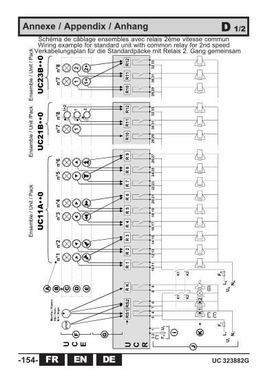
Annexe / Appendix / Anhang D 1/2Schéma de câblage ensembles avec relais 2ème vitesse communWiring example for standard unit with common relay for 2nd speed
Verkabelungsplan für die Standardpäcke mit Relais 2. Gang gemeinsam

UC 323882G -155-EN FRDE
English
Français
Annexe / Appendix / Anhang D 2/2
A- Boutons de fonction de l’émetteur UCEB- Positions des boutonsC- Position neutreD- 1ère vitesse (cran n°1)E- 2ème vitesse (cran n°2)F- Boutons de l’émetteur UCEG- Action des boutons de l’UCE sur les relais de
l’UCR
H- Relais du récepteur UCRi- Alimentation de l’UCRJ- Exemple de câblage externeK- Charges externes commandées (contacteurs
etc...)
(*) = Le raccordement de l'alimentation dépend du modèle de récepteur et de l'alimentation souhaitée.Bornes 2 - 1 pour alimentation 48 VAC, bornes 3 - 1 pour alimentation 230VAC ou 115VAC
(**) = L'utilisation de circuits limiteurs de surtension augmente la durée de vie des contacts des relais (ex: circuits RC enAC, diodes+Zener en DC etc...)
(***) = K1 et K2 sont des contacteurs à contacts guidés(****) = Eléments signalant le démarrage de l'équipement radiocommandé (Ex: Klaxon, feu tournant / flash, etc...)
Les relais de sécurité RS1 et RS2 sont enclenchés par le bouton "Marche", puis auto-maintenus jusqu'à appuisur le bouton d'arrêt coup de poing "STOP" (arrêt actif) ou déclenchement par perte de l'émission radio (arrêtpassif).
A- UCE function buttonsB- Button positionsC- Neutral positionD- 1st speed (Notch n°1)E- 2nd speed (Notch n°2)F- UCE buttonsG- UCE button actions on UCR relays
H- UCR receiver relaysi- UCR power supplyJ- External wiring exampleK- External driven loads (contactors etc...)
(*) = The power supply connection depends on the type of receiver and the power supply required.Terminals 2 - 1 for 48 VAC power supply, terminals 3 - 1 for 230VAC or 115VAC power supply.
(**) = Relay life is increased by the use of surge limiters (ex: RC network for AC, Zener + diodes for DC etc...)(***) = K1 and K2 must have guided contacts(****) = Elements which indicate start of remote controlled machines (Ex: Horn, rotaring / flashing light, etc...)
Safety relays RS1 and RS2 are switched ON by the pushbutton «On/Horn», and hold in position until the stoppalmswitch is pressed (active stop) or until the loss of radio transmission (passive stop).
DeutschA- Tasten Nr.B- TastenStellungC- RhuestellungD- 1.Gang (1.Stufe)E- 2.Gang (2.Stufe)F- UCE SendertastenG- Wirkung des Tasten des Senders UCE auf die
Relais des Empfängers UCR
H- Empfängerrelais UCRi- Strom. UCRJ- Beispiel für äußere VerkabelungK- Gesteuerte äußere-ladung
(*) = Der Anschluß der Stromversorgung hängt vom Empfängermodell und der gewünschten Stromversorgung ab.Anschlußklemmen 2 - 1 für Versorgungsspannung 48VAC oder 3 - 1 für 230VAC, 115VAC oder 24VDC.
(**) = Die Benutzung von Überspannungsschutzkreisen erhöht die Lebensdauer der Relaiskontakte (Bsp. : RC-Kreisemit AC, Dioden+Zener mit DC, etc.)
(***) = K1 und K2 sind Schütze mit Leitkontakten(****) = Elemente, die das Starten der funkfergesteuerten Ausrüstung anzeigen (Bsp. : Hupe, Blitzlampe, usw.)Die Sicherheitsrelais RS1 und RS2 werden mit dem Schalter "Ein" ausgelöst und selbstständig bis zuBetätigen des Notausknopfs "stop" (aktive Abschaltung) beibehalten oder Auslösen durch Sendeverlust(passives Abschalten).

-156- UC 323882GENFR DE
J
RS1
R K
STO
P
32
U C R5
48
9
U1
L1U0
F 0
1 N1
F 1
K1
(**)
(**)
(**)
*
U C E
**
(*)
K1
R 1
R 2
R 3
R 4
R 5
R 6
R 7
R 8
R 9
1011
1213
1415
1617
1819
2021
2223
2425
2627
R10
R11
R12
n°1
2829
3031
3233
UA
LA NA
F AK1
A B C D E
Mar
che
/ Kla
xon
ON
/ H
orn
Ein
/ Hup
e
F G H
i K
n°2
n°3
n°4
n°5
n°6
Ens
embl
e / U
nit /
Pac
k
UC
11B
••0
RS2
76 K
2K2
K2
Annexe / Appendix / Anhang E 1/2Schéma de câblage ensembles avec relais 2ème vitesse communWiring example for standard unit with common relay for 2nd speed
Verkabelungsplan für Standardpack UC11B**0 mit Relais 2. Gang getrennt
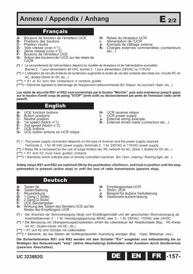
UC 323882G -157-EN FRDE
Annexe / Appendix / Anhang E 2/2
English
FrançaisA- Boutons de fonction de l’émetteur UCEB- Positions des boutonsC- Position neutreD- 1ère vitesse (cran n°1)E- 2ème vitesse (cran n°2)F- Boutons de l’émetteur UCEG- Action des boutons de l’UCE sur les relais de
l’UCR
H- Relais du récepteur UCRi- Alimentation de l’UCRJ- Exemple de câblage externeK- Charges externes commandées (contacteurs
etc...)
(*) = Le raccordement de l'alimentation dépend du modèle de récepteur et de l'alimentation souhaitée.Bornes 2 - 1 pour alimentation 48 VAC, bornes 3 - 1 pour alimentation 230VAC ou 115VAC
(**) = L'utilisation de circuits limiteurs de surtension augmente la durée de vie des contacts des relais (ex: circuits RC enAC, diodes+Zener en DC etc...)
(***) = K1 et K2 sont des contacteurs à contacts guidés(****) = Eléments signalant le démarrage de l'équipement radiocommandé (Ex: Klaxon, feu tournant / flash, etc...)
Les relais de sécurité RS1 et RS2 sont enclenchés par le bouton "Marche", puis auto-maintenus jusqu'à appuisur le bouton d'arrêt coup de poing "STOP" (arrêt actif) ou déclenchement par perte de l'émission radio (arrêtpassif).
A- UCE function buttonsB- Button positionsC- Neutral positionD- 1st speed (Notch n°1)E- 2nd speed (Notch n°2)F- UCE buttonsG- UCE button actions on UCR relays
H- UCR receiver relaysi- UCR power supplyJ- External wiring exampleK- External driven loads (contactors etc...)
(*) = The power supply connection depends on the type of receiver and the power supply required.Terminals 2 - 1 for 48 VAC power supply, terminals 3 - 1 for 230VAC or 115VAC power supply.
(**) = Relay life is increased by the use of surge limiters (ex: RC network for AC, Zener + diodes for DC etc...)(***) = K1 and K2 must have guided contacts(****) = Elements which indicate start of remote controlled machines (Ex: Horn, rotaring / flashing light, etc...)
Safety relays RS1 and RS2 are switched ON by the pushbutton «On/Horn», and hold in position until the stoppalmswitch is pressed (active stop) or until the loss of radio transmission (passive stop).
DeutschA- Tasten Nr.B- TastenStellungC- RhuestellungD- 1.Gang (1.Stufe)E- 2.Gang (2.Stufe)F- UCE SendertastenG- Wirkung des Tasten des Senders UCE auf die
Relais des Empfängers UCR
H- Empfängerrelais UCRi- Strom. UCRJ- Beispiel für äußere VerkabelungK- Gesteuerte äußere-ladung
(*) = Der Anschluß der Stromversorgung hängt vom Empfängermodell und der gewünschten Stromversorgung ab.Anschlußklemmen 2 - 1 für Versorgungsspannung 48VAC oder 3 - 1 für 230VAC, 115VAC oder 24VDC.
(**) = Die Benutzung von Überspannungsschutzkreisen erhöht die Lebensdauer der Relaiskontakte (Bsp. : RC-Kreisemit AC, Dioden+Zener mit DC, etc.)
(***) = K1 und K2 sind Schütze mit Leitkontakten(****) = Elemente, die das Starten der funkfergesteuerten Ausrüstung anzeigen (Bsp. : Hupe, Blitzlampe, usw.)Die Sicherheitsrelais RS1 und RS2 werden mit dem Schalter "Ein" ausgelöst und selbstständig bis zuBetätigen des Notausknopfs "stop" (aktive Abschaltung) beibehalten oder Auslösen durch Sendeverlust(passives Abschalten).
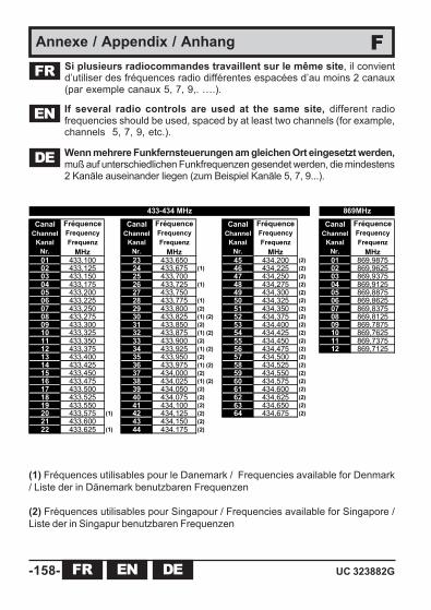
-158- UC 323882GENFR DE
CanalChannel
KanalNr.
FréquenceFrequencyFrequenz
MHz
CanalChannel
KanalNr.
FréquenceFrequencyFrequenz
MHz
CanalChannel
KanalNr.
FréquenceFrequencyFrequenz
MHz
CanalChannel
KanalNr.
FréquenceFrequencyFrequenz
MHz01 433,100 23 433,650 45 434,200 (2) 01 869,987502 433,125 24 433,675 (1) 46 434,225 (2) 02 869,962503 433,150 25 433,700 47 434,250 (2) 03 869,937504 433,175 26 433,725 (1) 48 434,275 (2) 04 869,912505 433,200 27 433,750 49 434,300 (2) 05 869,887506 433,225 28 433,775 (1) 50 434,325 (2) 06 869,862507 433,250 29 433,800 (2) 51 434,350 (2) 07 869,837508 433,275 30 433,825 (1) (2) 52 434,375 (2) 08 869,812509 433,300 31 433,850 (2) 53 434,400 (2) 09 869,787510 433,325 32 433,875 (1) (2) 54 434,425 (2) 10 869,762511 433,350 33 433,900 (2) 55 434,450 (2) 11 869,737512 433,375 34 433,925 (1) (2) 56 434,475 (2) 12 869,712513 433,400 35 433,950 (2) 57 434,500 (2)14 433,425 36 433,975 (1) (2) 58 434,525 (2)15 433,450 37 434,000 (2) 59 434,550 (2)16 433,475 38 434,025 (1) (2) 60 434,575 (2)17 433,500 39 434,050 (2) 61 434,600 (2)18 433,525 40 434,075 (2) 62 434,625 (2)19 433,550 41 434,100 (2) 63 434,650 (2)20 433,575 (1) 42 434,125 (2) 64 434,675 (2)21 433,600 43 434,150 (2)22 433,625 (1) 44 434,175 (2)
433-434 MHz 869MHz
Annexe / Appendix / Anhang FSi plusieurs radiocommandes travaillent sur le même site, il convientd’utiliser des fréquences radio différentes espacées d’au moins 2 canaux(par exemple canaux 5, 7, 9,. ….).
FR
EN If several radio controls are used at the same site, different radiofrequencies should be used, spaced by at least two channels (for example,channels 5, 7, 9, etc.).
(1) Fréquences utilisables pour le Danemark / Frequencies available for Denmark/ Liste der in Dänemark benutzbaren Frequenzen
(2) Fréquences utilisables pour Singapour / Frequencies available for Singapore /Liste der in Singapur benutzbaren Frequenzen
DE Wenn mehrere Funkfernsteuerungen am gleichen Ort eingesetzt werden,muß auf unterschiedlichen Funkfrequenzen gesendet werden, die mindestens2 Kanäle auseinander liegen (zum Beispiel Kanäle 5, 7, 9...).

UC 323882G -159-EN FRDE
Annexe / Appendix / Anhang GDéclaration de conformité CE / Emetteur UCEDeclaration of conformity / Transmitter UCEKonformitätserklärung CE / Sender UCE
Disponible en anglais et allemand :Available in English :Verfügbar auf deutscher Sprache :www.jay-electronique.fr

-160- UC 323882GENFR DE
Annexe / Appendix / Anhang GDéclaration de conformité CE / Récepteur UCRDeclaration of conformity / Receiver UCRKonformitätserklärung CE / Empfänger UCR
Disponible en anglais et allemand :Available in English :Verfügbar auf deutscher Sprache :www.jay-electronique.fr

UC 323882G -161-EN FRDE
MISE EN GARDE / WARNING / WARNUNG
V1V2V3
V1V2V3
V1V2V3
RRRR
V1V2V3
Annexe / Appendix / Anhang H
Kit prise BNC pour antenne débrochable / déportéeBNC plug kit for plug-in / deported antennaAbnehmbare Antenne BNC Kit OWR01 A B C
A
B C
FR Pour éviter tous risques d’électrocution, ne pas ouvrir le boîtier du récepteurlorsque celui ci est sous tension.
ENTo avoid any risks of electrocution, don't open the receiver case when powered.DEUm jegliche Stromschlagrisiken zu vermeiden, das Empfängergehäuse nicht
öffnen, solange es eingeschaltet ist.
OWR01
Récepteur UCR / UCR receiver/ UCR Empfänger

-162- UC 323882G
•Merci de nous faire parvenir cette page par courrier ou par fax à l’adresse suivante:•Please send us this form completed either by post or by fax at:•Bitte schicken Sie uns diese Seite per Fax oder per Post an folgende Adresse:
JAY ElectroniqueService documentation - Eric DECHAMEZAC la Bâtie, rue ChamprondF38334 SAINT ISMIER cedex - FRANCE
NomNameNameSociétéCompanyGesellschaftAdresseAddressAdresseVilleCityStadtCode postalePost codePostleitzahlTelFaxE.mail :
Page/Seite : ___
Page/Seite : ___
Page/Seite : ___
Page/Seite : ___
Page/Seite : ___
Améliorons ensemble ce manuel d’installation et d’utilisation !We can improve this manual with your assistance !
Helfen Sie uns bei der Verbesserung des Installations- undBenutzerhandbuchs !
Informations personnelles / Personal information / Persönliche Angaben:
«MERCI ! / THANKS ! / DANKE !»
Fax : +33.(0)4.76.41.44.44
Suggestions / Vorschlag :
UC 323882G -163-
NOTES :

Rea
lisat
ion
JAY
323
882G
-Not
ice_
inst
alla
tion_
Ser
ie_U
C-F
R-E
N-D
E.p
md
03.0
8.20
15 E
.DE
CH
AM
E.
d.A
ZAC la Bâtie, rue ChamprondF38334 SAINT ISMIER cedex +33 (0)4 76 41 44 00 - +33 (0)4 76 41 44 44www.jay-electronique.com
électronique