radio resource management for uplink carrier aggregation ... · pdf fileresearch open access...
TRANSCRIPT

Wang et al. EURASIP Journal on Wireless Communicationsand Networking (2015) 2015:121 DOI 10.1186/s13638-015-0329-y
RESEARCH Open Access
Radio resource management for uplink carrieraggregation in LTE-AdvancedHua Wang1*, Claudio Rosa2 and Klaus I Pedersen1,2
Abstract
This paper investigates the uplink resource allocation problem in the context of Long-Term Evolution (LTE)-Advancedsystems with carrier aggregation (CA) and dual-cluster scheduling. On one hand, these Rel’10 functionalities can increasethe available transmission bandwidth and scheduling flexibility in uplink. On the other hand, they will introduce additionalpower back-off for the power amplifier in the user equipment (UE) with non-contiguous resource allocation. Taking intoaccount that the uplink is inherently limited by the maximum transmission power of the UE, the assignment of uplink CAand/or dual cluster transmission for LTE-Advanced UEs has to be careful. A pathloss-threshold-based component carrier(CC) and cluster configuration algorithm is proposed to determine whether an LTE-Advanced UE should be configuredwith multiple CCs and/or dual cluster scheduling. An extended bandwidth-expansion-based packet scheduling algorithmis proposed for dual-cluster transmission, which tightly couples the bandwidth allocation and packet scheduling togetherto exploit the frequency domain diversity with low complexity. Simulation results show that with proper differentiationbetween power-limited and non-power-limited UEs, Rel’10 CA with dual-cluster scheduling can maintain similar coverageperformance as in Rel'8 case while achieving substantial gains in median and peak user throughputs. Moreover, theproposed CC assignment algorithm achieves higher user throughput as compared to blindly assigning all UEs on allavailable CCs.
1 IntroductionCarrier aggregation (CA) is one of the key features forLong-Term Evolution (LTE)-Advanced to support highertransmission bandwidth up to 100 MHz, enabling peakdate rates requirements of up to 1 Gbps in downlinkand 500 Mbps in uplink to be satisfied. This is achievedby aggregating two or more individual componentcarriers (CCs) of the same or different bandwidth be-longing to contiguous or non-contiguous frequencybands, subject to spectrum availability and the userequipment (UE)'s capability [1-5]. In addition to band-width extension enabled by CA, dual-cluster transmis-sion has also been introduced in Rel'10 to furtherimprove the spectral efficiency in uplink. With dual-cluster transmission, within a CC, a UE can be allocatedto a maximum of two non-contiguous clusters, each ofwhich includes one or more consecutive radio resourceblocks [6,7]. Dual-cluster scheduling has the advantage ofhigher scheduling flexibility as compared to single carrier
* Correspondence: [email protected] University, Fredrik Bajers Vej 7, DK-9220 Aalborg Ø, DenmarkFull list of author information is available at the end of the article
© 2015 Wang et al.; licensee Springer. This is aAttribution License (http://creativecommons.orin any medium, provided the original work is p
frequency division multiple access (SC-FDMA), whilekeeping the peak-to-average power ratio (PAPR) or signalcubic metric (CM) relatively low as compared to orthog-onal frequency division multiple access (OFDMA).In the open literature, there are quite many studies on
the topic of CA. The performance analysis of downlinkCA is investigated in [8-10]. Enhancements of downlinkcontrol channel resource allocation and mobilitymanagement for CA are studied in [11-13]. Differentcarrier load balancing schemes and packet schedulingalgorithms are analyzed in [14] by means of theoreticalformulations as well as system level simulations.Enhanced frequency diversity schemes for CA areexploited in [15-17]. However, most of the existing workon CA for LTE-Advanced is mainly concentrated on thedownlink. There are a few studies in the uplink. Anoverview of uplink multiple access transmission schemesin support of CA is provided in [18]. A dynamic uplinkCA scheme is proposed in [19] to improve the energy ef-ficiency of uplink communications. An edge-prioritizedchannel and traffic aware CC assignment resource andallocation algorithm is proposed in [20]. The performance
n Open Access article distributed under the terms of the Creative Commonsg/licenses/by/4.0), which permits unrestricted use, distribution, and reproductionroperly credited.

Wang et al. EURASIP Journal on Wireless Communications and Networking (2015) 2015:121 Page 2 of 15
of uplink CA in LTE-Advanced systems with different CCallocation schemes is investigated in [21-24].As different CCs may operate at different frequencies
and bandwidths, questions arise as how to assign theCCs to each user, and how to multiplex the users withineach CC. Different from the downlink, the UE is limitedby the maximum transmission power in the uplink,especially for cell edge users since they usually sufferfrom unfavorable channel conditions. Furthermore, anadditional power back-off is needed in the UE poweramplifier (PA) with non-contiguous resource allocationin the uplink, which in practice means a reduction of theUE maximum transmission power [25]. The UE trans-mission power constraint together with the additionalpower back-off required with non-contiguous resourceallocation might counterbalance the gain brought bymulti-CC and/or dual-cluster transmission and evenresults in a performance loss as compared to the casewithout CA where the SC-FDMA properties of the trans-mitted signals are maintained (single-CC and single-cluster transmission). Therefore, the selection of UEs tooperate with uplink CA has to be carefully considered.The CC selection for uplink CA has been studied in [22]for the case of intra-band contiguous CA and single-cluster transmission. In this paper, we extend the work of[22] to design efficient radio resource management(RRM) algorithms for uplink CA for cases of both intra-band contiguous CA and inter-band non-contiguousCA, as well as the support for multi-cluster transmission.Our main contributions are as follows:
1) We first focus on the derivation of a simple yeteffective pathloss-threshold-based CC configurationalgorithm which can be applied to both intra-bandCA and inter-band CA. The proposed algorithm takessome of the key uplink issues into considerations, suchas uplink power control and power back-offrequirements in the UE PA with non-contiguousresource allocation.
2) To support multi-cluster transmission with in a CC,an extended bandwidth-expansion-based packetscheduling algorithm is proposed based on the workin [23,26]. It aims at optimizing the resourceallocation with low computation complexity.
3) We present an extensive performance analysis underrealistic conditions. Due to the complexity of thesystem model and the various RRM elementsinvolved, the corresponding performance is bestevaluated via advanced system-level simulationsunder realistic multi-cell, multi-user conditions withdynamic birth-death traffic, using commonlyaccepted stochastic models and accuraterepresentation of the many mechanisms thatinfluence on the performance.
The rest of the paper is organized as follows: Section 2outlines the system model of RRM framework for LTE-Advanced, with special attention on multi-cluster trans-mission, UE power back-off model, and the uplinkpower control. The proposed CC configuration andpacket scheduling algorithms are described in Section 3.Section 4 introduces the simulation methodology andmain assumptions. Simulation results and performanceanalysis are presented in Section 5. Finally, some conclu-sions are drawn in Section 6.
2 System modelIn this study, it is assumed that eNodeB (eNB) antennasare collocated and have the same beam patterns for theCCs (also known as CA scenario 1 in the 3rd GenerationPartnership Project (3GPP)). This would be a typical sce-nario for intra-band CA when the CCs are within thesame band or different bands but with modest frequencyseparation, providing nearly the same coverage on all CCs.The RRM framework for multi-CC LTE-Advanced systemis illustrated in Figure 1. The layer-3 CC assignment mod-ule in the eNB configures one or multiple CCs for eachuser based on the quality-of-service (QoS) requirements,terminal capability, and CC deployment scenario, etc. Sep-arate RRM blocks such as independent link adaption,packet scheduling, and hybrid automatic repeat request(HARQ) operate independently on each CC in coherencewith LTE Rel'8 assumptions [5]. The channel state infor-mation (CSI) is extracted from sounding reference signals(SRS) sent by the UE and is used for packet schedulingand link adaptation. As a user may be assigned on mul-tiple CCs, the scheduler in each CC may need to exchangethe scheduling information across different CCs in orderto achieve better performance [14]. Since the UEs are lim-ited by the transmission power, uplink power control isalso an important issue. It is worth mentioning that thealgorithms for admission control, CC assignment, andpacket scheduling are not part of the standard but arevendor specific.
2.1 Types of CA and UE transceiver architectureThree types of CA have been defined by 3GPP [2]: 1)intra-band CA with contiguous CCs, 2) intra-band CAwith non-contiguous CCs, and 3) inter-band CA withnon-contiguous CCs. For the radio frequency (RF) as-pects of UEs supporting CA, two options are consideredfor the baseline UE transceiver architecture, illustratedin Figure 2 [27].
a) Single RF front-end with single wideband analog-to-digital converter (ADC) and dual base band (BB)processor
b) Dual RF front-ends with dual narrowband ADCsand dual BBs

Figure 2 UE transceiver architecture for supporting CA. (a) Single RF for intra-band CA; (b) multiple RF for inter-band CA.
Figure 1 RRM framework of a multi-component carrier LTE-Advanced system.
Wang et al. EURASIP Journal on Wireless Communications and Networking (2015) 2015:121 Page 3 of 15

Wang et al. EURASIP Journal on Wireless Communications and Networking (2015) 2015:121 Page 4 of 15
Option a) is only applicable for intra-band CA withcontiguous CCs, because it cannot filter undesired fre-quency bands between the non-contiguous CCs. The ad-vantage of option a) is keeping the UE transceivercomplexity low. For cases of non-contiguous CA, onlyoption b) is applicable at the expense of increased com-plexity. In this paper, we focus on intra-band CA withcontiguous CCs and inter-band CA with non-contiguousCCs. The default UE transceiver architectures for thetwo considered CA scenarios are therefore option a) andoption b), respectively.
2.2 Multi-cluster transmission in uplinkIn SC-FDMA, UEs in principle can only be scheduledon one set of continuous sub-carriers, which allows SC-FDMA to reach very low signal CM but with less sched-uling flexibility compared to OFDMA. Multi-clustertransmission has been introduced in Rel'10 to furtherimprove the spectral efficiency by allowing UEs to bescheduled on non-contiguous sub-carriers in the uplink.The minimum resource allocation unit in multi-clusterscheduling is a sub-band, which consists of an integernumber of physical resource blocks (PRBsa). Several con-tiguous sub-bands can be seen as a cluster, and a UE canbe allocated to multiple clusters not adjacent to eachother within one CC. Therefore, multi-cluster transmis-sion has higher scheduling flexibility compared to SC-FDMA while keeping the power back-off requirementsat the UE at a reasonable level. Though not consideredin this study, it is worth mentioning that the schedulingflexibility of multi-cluster transmission is particularbeneficial when combined with non-perfectly overlap-ping multi-user multiple-input and multiple-output(MU-MIMO) [28]. The three different multiple accessschemes are illustrated in Figure 3. A maximum of twoclusters within each CC are supported in Rel'10. Thesub-band size is a fixed value and depends on the uplinksystem bandwidth [6]. In our study, the sub-band sizecorresponds to two PRBs.
Figure 3 Different multiple access schemes in LTE-Advanced.
2.3 Maximum power reduction for non-contiguousallocationWith a single RF front-end at the UE side (e.g., UEssupporting intra-band CA), the UE may be allocatednon-contiguous resources when transmitting overmultiple CCs, thus the single carrier property of SC-FDMA is no longer preserved. The increased CM ofthe transmitted signal with non-contiguous resourceallocation, and the need to still fulfill the in-band andout-band emission masks [29] require the UE PA tooperate with an additional power back-off [27-29].Furthermore, the multi-cluster transmission within aCC imposes more stringent linearity requirements onthe PA. The exact value of the required power back-off is hard to determine as it is UE implementationspecific and is affected by many aspects of the spe-cific uplink resource allocation such as modulationand coding scheme (MCS), number of clusters, sizeof clusters, frequency separation between clusters,distance from the edge of the first/last cluster to theleft/right hand edge of the first/last CC, etc. [30,31].In this study, we adopt the maximum power reduc-tion (MPR) mask equation proposed by 3GPP [25],though in practice the proposed MPR mask only rep-resents an upper bound of the required power back-off. The MPR value (in dB) is determined solely basedon the ratio between the allocated and the availablebandwidth aggregated from the assigned CCs. Formulti-CC transmission, the estimated MPR mask iscalculated as:
PCAMPR ¼
8:2;9:2−40A;8−16A;
4:83−3:33A;3:83−0:83A;
0 < A < 0:0250:025 < A ≤ 0:050:05 < A ≤ 0:250:25 < A ≤ 0:40:4 < A ≤ 1
8>>>><>>>>:
ð1Þ

Wang et al. EURASIP Journal on Wireless Communications and Networking (2015) 2015:121 Page 5 of 15
In case of single CC with multi-cluster transmission,the estimated MPR mask is given by:
PSCMPR ¼
8−10:2A;5:67−3:07A;
3:31;
0 < A ≤0:330:33 < A ≤0:770:77 < A ≤1
8<: ð2Þ
where A = NPRB_alloc/NPRB_agg is the ratio between thenumber of allocated PRBs (NPRB_alloc) and total availablePRBs over all assigned CCs (NPRB_agg).With dual RF front-ends at the UE side (e.g., UEs
supporting inter-band CA), each carrier is amplifiedby a separate PA and the two carriers are added upin the combiner as illustrated in Figure 2. In thiscase, the power back-off issue is less important if twoPA are sufficiently isolated from each other. Note thatthe use of a combiner results in insertion loss of atleast 2 dB [27]. However, if multi-cluster transmissionis enabled within each CC, power back-off is stillneeded in the UE PA with the MPR value specified inEquation 2. It is worth mentioning that the powerback-off model for inter-band CA with multi-clustertransmission is built from existing models using sim-plified assumptions. Table 1 summarizes the requiredpower back-off values for different CA types and up-link resource allocation schemes.
2.4 Uplink power controlAs the UE is limited by the maximum transmissionpower, the uplink power control is an important issue. Itconsists of open loop power control and closed looppower control. The open loop power control aims atcompensating for slow variations of channel conditions,i.e., pathloss and shadowing. The closed loop power con-trol targets at further adjusting the UE’s transmissionpower to optimize the system performance.In Rel’10, independent power control is applied in
each CC so that Rel'8 power control formula can also bereused in case of CA. The estimated transmission poweron each assigned CC depends on the allocated band-width and on the CC specific power control parameters.When user i is scheduled for transmission on CC k, the
Table 1 Required power back-off values for differenttypes of CA and uplink resource allocation schemes
CA type Resourceallocation
Required powerback-off (dB)
Intra-band CA withone RF front-end
Multi-CC transmission PCAMPR
Single-CC with multi-cluster PSCMPR
Single-CC with single-cluster 0
Inter-band CA withdual RF front-ends
Multi-CC with single-cluster 2
Multi-CC with multi-cluster PSCMPR + 2
estimated transmission power ~Pi;k tð Þ, expressed in dBm,is calculated as [32]:
~Pi;k tð Þ ¼ 10 log10Mi;k tð Þ þ P0;k tð Þ þ f Δi;k tð Þ� �þ αk⋅Li;k
ð3Þ
where Mi,k(t) is the number of PRBs allocated to user ion CC k, P0,k(t) is the normalized power density on CCk, αk is the pathloss compensation factor on CC k, Li,k isthe measured pathloss between user i and its servingbase station on CC k, and f(Δi,k(t)) is the closed looppower control correction for user i on CC k. Moredetails on the uplink power control formula for LTE-Advanced with CA can be found in [7].Previous studies [33,34] have shown that the system
performance in terms of coverage (5th percentile userthroughput) and cell throughput is highly dependent onthe setting of P0,k and αk. Load adaptive power control(LAPC) is proposed in [34] to dynamically adjust theusers' power spectral density P0,k. If the optimizationgoal is to maximize the coverage, the 5th percentile celledge users should transmit with the maximum transmis-sion power. Then, the power spectral density is updatedperiodically according to the following equation:
P0;k tð Þ þ f Δi;k tð Þ� � ¼ Pmax−10 log10Mk tð Þ−αk⋅L95%;k
ð4Þ
where Pmax is the maximum UE transmission power indBm, Mk(t) is the estimated average number of allocatedPRBs allocated to each user on CC k, and L95 %,k is theestimated 95th percentile user pathloss in the corre-sponding cell on CC k. For simplicity, �Mk tð Þ is approxi-mated as the total number of available PRBs divided bythe number of UEs served by the corresponding cell.Because power control is performed independently
within each CC, the aggregated transmission power allo-cated over all CCs may exceed the maximum UE transmis-sion power constraint even if the individual transmissionpower within each CC is below the limit. In this case, theUE needs to scale down the transmission power with differ-ent priorities according to the channel type [35]. In ourstudy, the reduction of transmission power for user i oneach assigned CC follows the same ratio. The actual trans-mission power Pi,k(t) of user i on CC k then becomes:
Pi;k tð Þ ¼ ~Pi;k tð Þ−max 0 ; 10 log10XNk¼1
10~Pi;k tð Þ=10
!− Pmax−Pbackoffð Þ
( )
ð5Þ
where N is the number of CCs assigned to user i, andPbackoff is the required power back-off with the valueslisted in Table 1.

Wang et al. EURASIP Journal on Wireless Communications and Networking (2015) 2015:121 Page 6 of 15
3 Component carrier configuration and packetschedulingThe two main RRM functionalities that determine theradio resource allocation among the users in the systemare the layer 3 CC configuration which selects a CC setfor each user, and the layer 2 packet scheduling whichallocates the resources among the admitted users oneach CC. Hence, these two RRM functionalities are alsothe ones that impact the most on the performance ofuplink CA. The proposed algorithms for these two setsof RRM algorithms are therefore motivated and outlinedin the following.
3.1 Component carrier configurationIn a multi-CC LTE-Advanced system, both legacy andLTE-Advanced users may co-exist. The legacy Rel'8users naturally can only be assigned on a single CC.With intra-band CA, the radio channel characteristicsof different CCs are more or less the same. For optimalsystem performance, it is desirable to distribute the loadequally on each CC. So, a simple yet effective load bal-ancing scheme is applied for Rel'8 users, which assignsthe CC with the least load (e.g. the number of users).With inter-band CA, the radio channel characteristicscan be different at different frequency carriers. Thestudy in [10] indicates that the CC selection should takeboth traffic load and radio channel characteristics intoconsiderations. Therefore, with inter-band CA, cell-edge Rel’8 users (e.g., 5th percentile in pathloss distribu-tion) are assigned to the CC with better coverage (i.e.,low-frequency carrier) to improve the coverage per-formance, while other Rel’8 users are assigned to theCC with the least number of users to balance the loadon each CC.LTE-Advanced users can be assigned on multiple CCs.
A CC is defined as its primary cell (PCell) and can onlybe changed via handover. Different users may not neces-sarily use the same CC as their PCell. If more than oneCC is configured, the additional CCs are denoted as sec-ondary cells (SCells). The SCells can be activated/deacti-vated by explicit signaling from the eNodeB, as well asbased on appositely configured timers [36].LTE-Advanced users configured with multiple CCs
have the possibility to transmit on multiple CCs usingthe corresponding power control settings in each CC,therefore requiring higher transmission power as com-pared to the case with single CC configuration. Config-uring LTE-Advanced users with multiple CCs and/ordual-cluster transmission in principle only makes senseif its total transmission power does not exceed themaximum UE power capability. Otherwise, they do nothave sufficient power to exploit the increased transmis-sion bandwidth and scheduling flexibility. For an LTE-
Advanced user i assigned on N CCs, the total transmis-sion power is calculated as:
Pi tð Þ ¼ 10 log10XNk¼1
10Pi;k tð Þ=10 !
≤Pmax−Pbackoff ð6Þ
Substituting Equations 3 and 4 into Equation 6 andassuming Mi,k(t) =Mk(t), we obtain:
XNk¼1
10αk Li;k−L95%;kð Þ
10 ≤10Pbackoff
10 ð7Þ
where Pbackoff is the expected power back-off with non-contiguous resource allocation. So with uplink CA,Equation 7 can be used to estimate whether the UE hasenough transmission power to manage transmissions onmultiple CCs simultaneously, assuming LAPC is applied.For the case of intra-band CA, it is often assumed that αkand L95 %,k are the same on each CC k, then Equation 7can be further simplified into:
Li≤L95%−10 log10N þ Pbackoff
αð8Þ
Based on the derived pathloss threshold, we propose aCC configuration algorithm for uplink CA. The idea isto distinguish between power-limited and non-power-limited users. LTE-Advanced users whose pathloss satis-fies Equation 7 are considered to be non-power-limitedand can be assigned on multiple CCs with dual-clustertransmission. Otherwise, they are considered to bepower-limited and are only assigned on one CC withsingle-cluster transmission. The selection of the CC forpower-limited LTE-Advanced users is the same as forRel'8 users. By separating the power-limited and non-power-limited LTE-Advanced users, cell-edge LTE-Advanced users will not experience any performanceloss with non-contiguous resource allocation, while non-power-limited LTE-Advanced users can benefit fromincreased transmission bandwidth and scheduling flexi-bility with CA and multi-cluster transmission. It is worthmentioning that with non-contiguous resource alloca-tion, the required power back-off specified in Equation 1is not dependent on the number of clusters, but ratherdepends on the ratio between the allocated and totalavailable bandwidth [30]. Therefore, for non-power-limited LTE-Advanced users, it is always beneficial touse dual-cluster transmission in combination with CA inorder to increase the scheduling flexibility. The proposedCC and multi-cluster configuration algorithm is illus-trated in Figure 4.
3.2 Bandwidth allocation and packet schedulingAfter the CC and cluster assignment for each user, thelayer 2 time and frequency domain packet scheduler

Figure 4 Proposed CC and multi-cluster configuration algorithm in uplink LTE-Advanced.
Wang et al. EURASIP Journal on Wireless Communications and Networking (2015) 2015:121 Page 7 of 15
allocates the resources in terms of PRBs among the ad-mitted users on each CC according to certain con-straints with the objective to improve the spectralefficiency while maintaining fairness among scheduledusers. The use of sounding reference signals (SRS) allowsfor uplink link adaptation and channel-aware frequencydomain packet scheduling [7]. The eNB may configurethe SRS patterns on each carrier depending on the ac-curacy of uplink SRS measurements.In [26], the authors proposed an adaptive transmission
bandwidth (ATB)-based packet scheduling algorithm forSC-FDMA with single-cluster transmission in uplink,which tightly couples the bandwidth allocation and thepacket scheduling together to exploit the bandwidthflexibility. In this study, we extend the ATB algorithm sothat it is catered to support multi-cluster transmission[23]. With multi-cluster transmission, the allocated PRBsfor a user can be non-contiguous subject to the con-straint of not exceeding the maximum number of con-figured clusters, which is determined according to thealgorithm depicted in Figure 4. The basic idea behindthe proposed scheduling algorithm is to produce an allo-cation table which closely follows the envelope of theUEs' scheduling metrics.We assume that packet scheduling is performed in each
CC. The well-known proportional fair (PF) scheduler isapplied. The problem with baseline PF scheduler is that itwill allocate more resources to the users connected tomultiple CCs (with CA) than users without CA, resultingin an unfair resource allocation. Therefore, cross-carrierPF scheduling across multiple CCs is recommended when
calculating the scheduling metric in each CC [14]. Incross-carrier PF scheduler, the denominator of the PFmetric is calculated as the sum of the average scheduledthroughput over all CCs where the user has been assignedand scheduled in the past. By applying this modification,the scheduler can distribute the radio resources amongthe users more fairly. It simply requires information ex-change on the average scheduled throughput across differ-ent CCs. The scheduling metric of user i at sub-band j onCC k, denoted as Mi,j,k, is therefore calculated as:
Mi;j;k tð Þ ¼ Ri;j;k tð ÞXN
k¼1Ri;k tð Þ
ð9Þ
where Ri,j,k(t) is the estimated throughput of user i atsub-band j on CC k, and Ri,k(t) is the exponentially fil-tered average throughput of user i on CC k.At each scheduling instance, the scheduler in each CC
first generates a scheduling matrix of each user on eachsub-band. Then, the scheduler selects a UE and the corre-sponding sub-band with the highest scheduling metric andchecks the power constraint of that UE with Equation 3. Ifthe selected UE exceeds its maximum transmission powercapability with the new resource allocation, the schedulerremoves that UE from the candidate list and reselects theUE and the sub-band from the scheduling matrix. After thepower constraint check, the scheduler checks the numberof allocated clusters of the selected UE. If the new resourceallocation causes the number of allocated clusters to exceedthe maximum number of configured clusters (i.e., single-cluster for Rel’8 and power-limited LTE-A users, and dual-

Wang et al. EURASIP Journal on Wireless Communications and Networking (2015) 2015:121 Page 8 of 15
cluster for non-power-limited LTE-A users), the currentsub-band is disabled for that UE and the algorithm restartsfrom the beginning. Otherwise, the scheduler allocates thecurrent sub-band to that UE and expands its transmissionbandwidth to the adjacent sub-bands on both sides untileither another UE has a higher scheduling metric or themaximum transmission power of that UE is exceeded. De-tails of the bandwidth expansion procedure can be found in[26]. Then, the algorithm restarts from the beginning andcontinues the loop until either all UEs have been scheduledor there are no resources left. A detailed description of theproposed multi-cluster scheduling algorithm is illustratedin Figure 5 [23].
4 Simulation assumptionsThe performance of the proposed algorithms is evalu-ated in a quasi-static uplink multi-cell system level simu-lator that follows the LTE specifications defined in [37],including detailed modeling of major RRM functional-ities such as layer 3 CC configuration, layer 2 packetscheduling, HARQ, link adaptation, and uplink powercontrol. The simulation scenario is 3GPP macro-cellcase number 1 with seven sites and three sectors per siteusing the wrap-around technique. A directional 3D an-tenna pattern with default 15° down-tilt is modeled forthe macro cells. The ITU defined geometrical channelmodel is applied, where UE to macro links follow theurban macro model (UMa), which includes separatemodels for line-of-sight (LOS) and non-LOS (NLOS)[38]. Selection between the LOS and NLOS model is
Figure 5 Proposed uplink multi-cluster scheduling algorithm in LTE-Advan
random for each link, where the probabilities for select-ing LOS or NLOS vary with the distance between theUE and eNB. Small-scale fading (also known as fast fad-ing) is modeled according to the commonly acceptedstochastic typical urban model. It is assumed thatdistance-dependent path loss and shadowing are main-tained constant for each UE, but fast fading is updatedevery TTI independently on each CC based on the ITUtypical urban power delay profile and UEs' speed. Forintra-band CA, two CCs each with 20 MHz bandwidthare deployed at 2 GHz. For inter-band CA, two CCseach with 20 MHz bandwidth are deployed at 1.8 and2.6 GHz, respectively. Up to two clusters are supportedin each CC for uplink multi-cluster transmission. TheSRS resolution is two PRBs and the SRS period is set tobe ten subframes. Imperfect SRS measurements are as-sumed. The measurement error is a function of the ex-perienced signal-to-interference-plus-noise ratio (SINR)and sounding bandwidth. The link to system level map-ping is based on the actual value interface (AVI) method[39], including channel estimation error with uplinkclustered transmission which is modeled by modifyingthe experienced SINR before it is used for AVI mapping.Both full buffer and bursty traffic models are considered.In full-buffer traffic model, we assume each sector has afixed number of UEs with full buffer traffic. For burstytraffic model, a dynamic birth-death traffic model isapplied for generating user calls, where call arrival isaccording to a Poisson process with arrival rate λ persector. Each call has a finite payload size of B = 2 Mbits.
ced.

Wang et al. EURASIP Journal on Wireless Communications and Networking (2015) 2015:121 Page 9 of 15
Once the payload has been successfully transmitted bythe UE, the call is terminated and the UE is removedfrom the simulation. Thus, the average offered load persector equals λ × B. Joint proportional fair scheduling infrequency domain is used together with multi-clusterbandwidth allocation. Independent LAPC is enabled oneach CC to dynamically adjust the UE power spectraldensity based on the variable load conditions. Theoptimization goal is to maximize the 5th percentile celledge user throughput. The average UE power back-offPbackoff with non-contiguous resource allocation is set tobe 6 dB (close to worst-case assumption considering thepower back-off model in Equation 1). Table 2 summa-rizes the main parameter settings used in the system-level simulations.
5 Simulation results and analysis5.1 Multi-cluster transmission gain in uplinkWe start our analysis by first looking at the scenario witha fixed number of UEs per sector and full-buffer trafficmodel. Only one CC is configured with 10 MHz@2 GHzin this scenario. Figure 6 shows the dual-cluster schedul-ing gain over single-cluster scheduling and the averagenumber of scheduled clusters per UE versus the differentnumber of UEs per macro sector, respectively. It is shownthat the dual-cluster scheduling gain is closely correlatedto the average number of scheduled clusters per UE. Spe-cifically, the dual-cluster scheduling gain increases as thenumber of UEs increases until reaching the maximumvalue, i.e., 16% gain at six UEs per macro sector in ourcase. Then, the gain gradually decreases as the number ofUEs increases. That is because when the number of UEsper macro sector is low (e.g., less than six), dual-clusterscheduling users have more chance to exploit the increasedfrequency diversity order as compared to single-clustertransmission. However, when the number of UEs permacro sector is high (e.g., larger than six), the probabilityof a user being scheduled on multiple clusters decreases,therefore the gain brought by dual-cluster schedulingdecreases.
5.2 Effectiveness of the proposed CC configurationalgorithmNext, we evaluate the effectiveness of the derived path-loss threshold in Equation 8 against other pathlossthresholds with bursty traffic model. Two contiguousCCs each with 20 MHz bandwidth are configured forintra-band CA in this scenario. Figure 7 shows the 5thpercentile and 50th percentile user throughput versusthe different pathloss thresholds under different trafficloads (5 and 20 Mbps offered loads correspond to ap-proximately 20% and approximately 70% PRB utilization,respectively). Here, we assume 100% LTE-AdvancedUEs. The 5th percentile user throughput stays almost
constant when the pathloss threshold is smaller than acertain value (approximately 109 dB). After that point,the 5th percentile user throughput decreases as thepathloss threshold increases. For the 50th percentile userthroughput, it increases as the threshold increases untilthe maximum value is reached also around 109 dB.Then, the throughput decreases with further increase ofthe pathloss threshold. The reasons are as follows: if thepathloss threshold is set to be low, most UEs, includingpower-limited and some non-power-limited UEs areonly assigned on one CC with single-cluster transmis-sion. As a result, those non-power-limited UEs cannotbenefit from the advantages of transmission bandwidthexpansion by using CA and increased scheduling flexi-bility with dual-cluster transmission. Therefore, smallvalue of the threshold would decrease the 50th percent-ile user throughput. The 5th percentile user throughputremains steady as they are assigned only on one CC. Onthe other hand, if the pathloss threshold is set to behigh, not only non-power-limited but also some power-limited UEs are assigned on both CCs with dual-clustertransmission. As a result, those power-limited cell edgeUEs will experience performance loss from being sched-uled over multiple CCs and clusters due to the effect ofadditional power back-off with non-contiguous resourceallocation. Since cell edge users usually utilize the re-sources with low efficiency due to poor channel condi-tions, the increase of their activity time in the networkworsens the resource utilization of other users. There-fore, higher value of the threshold would decrease boththe 5th percentile and 50th percentile user throughput.As a conclusion, the value of pathloss threshold has tobe carefully determined in order to optimize the systemperformance. It is shown from Figure 7 that our derivedpathloss threshold works effectively to achieve good per-formance at both 5th percentile and 50th percentile userthroughput under different traffic conditions. Thus, it isrobust against variations in the traffic load.
5.3 Overall performanceThen, we evaluate the performance of intra-band andinter-band CA with the proposed CA algorithm as com-pared to the case without CA in a bursty traffic model.The performance with 'blind' CC configuration (i.e. allUEs are configured with uplink CA) is also included forcomparisons. Figure 8 shows the 5th percentile userthroughput versus the offered load with different CAand multi-cluster transmission schemes. As expected,the user throughput decreases as the load in the networkincreases. For intra-band CA, there is a performance lossif all UEs are configured with CA and/or multi-clustertransmission, as compared to the case without CA andsingle-cluster transmission. This is because at the celledge, UEs usually experience large pathloss and are

Table 2 Summary of main simulation parameters
Parameters Settings
Simulation scenario 3GPP macro case number 1
Network layout Seven macro sites - three sectors/site - wrap around
Channel model (UMa) [38]a LOS pathloss 22 log10(d) + 28.0 + 20.0 log10(f), shadow fading std = 4 dB, 10 m < d < d0BP
40 log10 dð Þ þ 7:8−18 log10 h0BS
� �−18 log10 h
0UT
� �þ 2 log10 fð Þ, shadow fading
std = 4 dB, d0BP < d < 5; 000 m
NLOS pathloss 161.04 − 7.1 log10(W) + 7.5 log10(h) − (24.37 − 3.7(h/hBS)2)log10(hBS) +
(43.42 − 3.1 log10(hBS))(log10(d) − 3) + 20.0 log10(f) − (3.2(log10(11.75hUT))2 − 4.97),
shadow fading std = 6 dB, 10 m < d < 5, 000 m
LOS probability min 18d ; 1� �
1− exp − d63
� �� �þ exp − d63
� �Inter-site distance 500 m
Component carriers Intra-band CA: 2 × 20 MHz @ 2 GHz, inter-band CA: 20 [email protected] GHz + 20 [email protected] GHz
96 available PRBs for PDSCH per CC
Number of clusters Single or dual clusters
PRBs per sub-band Two PRBs
Sounding resolution Two PRBs
Sounding period Ten subframes
Sounding method Imperfect SRS
eNode-B receiver 4-Rx MMSE
Max UE power 200 mW (23 dBm)
UE transceiver Single transceiver for intra-band CA
Two separate transceivers for inter-band CA
UE Tx bandwidth ATB for multi-cluster
Packet scheduling Joint proportional fair
Bursty traffic model Finite buffer with different Poisson arrival rate
Fixed payload size of 2 Mbits per UE
Full-buf. traffic model Full buffer with fixed number of UEs
UE speed 3 km/h
Available MCSs BPSK (R = 1/5,1/3)
QPSK (R = 1/4,1/3,1/2,2/3,3/4)
16 QAM (R = 1/2,2/3,3/4,5/6)
HARQ Synchronous and adaptive with maximum of four transmissions
First Tx BLER target 20%
Link adaptation Fast adaptive modulation and coding (AMC)
Pathloss compensation α = 0.8
95th percentile user pathloss 118 [email protected] GHz, 120 dB@2 GHz, 123 [email protected] GHz
Power spectral density Independent LAPC in each CC [34]
Average power back-off Pbackoff = 6 dBaf is the center frequency (Hz), hBS and hUT are the actual antenna heights at the BS and the UT (m), h
0BS and h
0UT are the effective antenna heights at the BS and
the UT (m), d is the distance (m), d0BP is the break point distance d
0BP ¼ 4h
0BSh
0UT f=c where c is the propagation velocity in free space, W is the street width (m), and
h is the average building height (m).
Wang et al. EURASIP Journal on Wireless Communications and Networking (2015) 2015:121 Page 10 of 15
limited by the transmission power. In fact, with LAPC, celledge UEs (worst 5th percentile UEs) are configured totransmit with the maximum transmission power on theassigned CC. Transmitting over multiple CCs and/or mul-tiple clusters will cause further power reduction due to theeffect of additional power back-off with non-contiguous re-source allocation, therefore degrading the 5th percentile UE
throughput performance. In the proposed CA algorithm,the power-limited cell edge UEs are only assigned on oneCC with single-cluster transmission so that the SC-FDMAproperties of the transmitted signals are maintained. There-fore, there is no performance loss as compared to Rel'8operation. For inter-band CA with single-cluster transmis-sion, the performance is slightly worse as compared to

Figure 6 Multi-cluster scheduling gain with full buffer traffic.
Wang et al. EURASIP Journal on Wireless Communications and Networking (2015) 2015:121 Page 11 of 15
the case of intra-band CA, due to the 2-dB insertionloss in the combiner with two RF front-ends and thehigher frequency band used for inter-band CA. Forinter-band CA with dual-cluster transmission, thedual-cluster transmission should be avoided for cell
Figure 7 5th and 50th percentile user throughput with different pathloss t
edge users as it will cause additional power back-offsimilar to the case of intra-band CA.Figure 9 shows the 50th percentile user throughput
versus the offered load with different CA and multi-cluster transmission schemes. For intra-band CA, the
hresholds, with 5 and 20 Mbps offered load.

Figure 8 5th percentile user throughput under different traffic loads in different scenarios.
Wang et al. EURASIP Journal on Wireless Communications and Networking (2015) 2015:121 Page 12 of 15
user throughput with the proposed CA algorithm is sig-nificantly higher than that with 'blind' CA configurationand the case without CA. Also, it is observed that dual-cluster transmission can further increase the userthroughput. That is because with 'blind' CA configur-ation, cell edge UEs will stay in the system for longer
Figure 9 50th percentile user throughput under different traffic loads in d
time due to the poor performance as shown in Figure 8,therefore occupying more resources. In the proposedCA algorithm, only the non-power-limited UEs areassigned on multiple CCs with dual-cluster transmissionso that they can benefit from the advantages of CA (i.e.,increased transmission bandwidth with multiple CCs)
ifferent scenarios.
Wang et al. EURASIP Journal on Wireless Communications and Networking (2015) 2015:121 Page 13 of 15
and dual-cluster scheduling (i.e., increased schedulingflexibility within one CC). The power-limited cell edgeusers are configured only on one CC with single-clustertransmission so that they will not suffer from performanceloss. For the case of inter-band CA, similar phenomenoncan be observed.From Figure 8 and 9, it clearly suggests avoiding using
uplink CA and dual-cluster transmission at cell edge butactivating them when a user is identified to be in a non-power-limited region in order to benefit from increasedtransmission bandwidth and scheduling flexibility. Atlow load, the 50th percentile user throughput gain withCA as compared to the case without CA lies in therange of 70% to 80%. When the load increases, the prob-ability of a user being scheduled on both CCs is reduced,and so is the gain.Figure 10 shows the empirical cumulative distribution
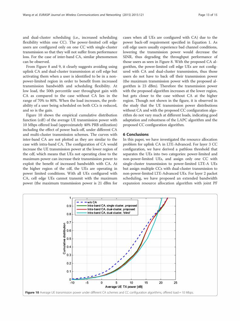
function (cdf) of the average UE transmission power with10 Mbps offered load (approximately 40% PRB utilization)including the effect of power back-off, under different CAand multi-cluster transmission schemes. The curves withinter-band CA are not plotted as they are similar to thecase with intra-band CA. The configuration of CA wouldincrease the UE transmission power at the lower region ofthe cdf, which means that UEs not operating close to themaximum power can increase their transmission power toexploit the benefit of increased bandwidth with CA. Atthe higher region of the cdf, the UEs are operating inpower limited conditions. With all UEs configured withCA, cell edge UEs cannot transmit with the maximumpower (the maximum transmission power is 21 dBm for
Figure 10 Average UE transmission power under different CA schemes an
cases when all UEs are configured with CA) due to thepower back-off requirement specified in Equation 1. Ascell edge users usually experience bad channel conditions,lowering the transmission power would decrease theSINR, thus degrading the throughput performance ofthose users as seen in Figure 8. With the proposed CA al-gorithm, the power-limited cell edge UEs are not config-ured with CA and dual-cluster transmission, thus thoseusers do not have to back off their transmission power(the maximum transmission power with the proposed al-gorithm is 23 dBm). Therefore the transmission powerwith the proposed algorithm increases at the lower region,but gets closer to the case without CA at the higherregion. Though not shown in the figure, it is observed inthe study that the UE transmission power distributionswithout CA and with the proposed CC configuration algo-rithm do not vary much at different loads, indicating goodadaptation and robustness of the LAPC algorithm and theproposed CC configuration algorithm.
6 ConclusionsIn this paper, we have investigated the resource allocationproblem for uplink CA in LTE-Advanced. For layer 3 CCconfiguration, we have derived a pathloss threshold thatseparates the UEs into two categories: power-limited andnon-power-limited UEs, and assign only one CC withsingle-cluster transmission to power-limited LTE-A UEsbut assign multiple CCs with dual-cluster transmission tonon-power-limited LTE-Advanced UEs. For layer 2 packetscheduling, we have proposed an extended bandwidthexpansion resource allocation algorithm with joint PF
d CC configuration algorithms, offered load = 10 Mbps.

Wang et al. EURASIP Journal on Wireless Communications and Networking (2015) 2015:121 Page 14 of 15
scheduling that closely follows the envelope of theUEs' scheduling metrics. The performance of the pro-posed resource allocation algorithms has been evalu-ated for intra-band and inter-band CA via systemlevel simulations. It is recommended that uplink CAand multi-cluster scheduling should not be configuredfor cell edge users, due to the limitation of UE’stransmission power and the additional power back-offrequirements when transmitting over non-contiguousresources. On the other hand, CA and multi-clusterscheduling should be configured for non-power-limited UEs so that they can benefit from increasedtransmission bandwidth and scheduling flexibility.The results show that intra-band and inter-band CAexhibit similar trend. Specifically, with the proposedCC configuration algorithm, there is no loss at 5thpercentile user throughput and up to 70% to 80%gain can be achieved at 50th percentile user through-put, as compared to the case without CA and dual-cluster transmission. The throughput gain is especiallyvisible at low load but decreases gradually as the loadincreases. Refinements of the power back-off modelused for inter-band CA with dual-cluster transmissionand other uplink power control methods could be in-teresting topics for future studies.
7 EndnotesaIn LTE, a PRB consists of 12 sub-carriers, each of
which is 15 kHz, and is thus equal to 180 kHz.
Competing interestsThe authors declare that they have no competing interests.
AcknowledgementThe authors would like to express their gratitude to Nokia Networkscolleagues Huiyu Yuan, Yuyu Yan, Jens Steiner, and Mads Brix for theirassistance in the development of the system-level simulator.
Author details1Aalborg University, Fredrik Bajers Vej 7, DK-9220 Aalborg Ø, Denmark. 2NokiaNetworks, Alfred Nobel Vej 21, DK-9220 Aalborg, Ø, Denmark.
Received: 23 September 2014 Accepted: 10 March 2015
References1. A Ghosh, R Ratasuk, B Mondal, N Mangalvedhe, T Thomas, LTE-advanced:
next-generation wireless broadband technology. IEEE Wirel. Commun.17(3), 1536–1284 (2010)
2. G Yuan, X Zhang, W Wang, Y Yang, Carrier aggregation for LTE-advancedmobile communication systems. IEEE Wirel. Commun. 48(2), 88–93 (2010)
3. M Iwamura, K Etemad, F Mo-Han, R Nory, R Love, Carrier aggregationframework in 3GPP LTE-Advanced. IEEE Commun. Mag. 48(8), 60–7 (2010)
4. S Zukang, A Papasakellariou, J Montojo, D Gerstenberger, X Fangli,Overview of 3GPP LTE-advanced carrier aggregation for 4Gwirelesscommunications. IEEE Commun. Mag. 50(2), 122–30 (2012)
5. K Pedersen, F Frederiksen, C Rosa, H Nguyen, L Garcia, W Yuanye, Carrieraggregation for LTE-Advanced: functionality and performance aspects.IEEE Commun. Mag. 49(6), 89–95 (2011)
6. 3GPP TS 36.213, v10.12.0, Release 10 physical layer procedures, March 2014.Available at www.3gpp.org/dynareport/36213.htm
7. H Holma, A Toskala, LTE for UMTS: Evolution to LTE-Advanced, 2nd edn.(John Wiley & Sons, Chichester, UK, 2011)
8. L Chen, W Chen, X Zhang, D Yang, Analysis and simulation for spectrumaggregation in LTE-Advanced system, Paper presented at the 2009 IEEEvehicular technology conference (VTC) Fall, IEEE, Anchorage, AK,20–23 September 2009
9. Y Kakishima, T Kawamura, Y Kishiyama, H Taoka, T Nakamura, Experimentalevaluation on throughput performance of asymmetric carrier aggregationin LTE-Advanced, Paper presented at the 2011 IEEE vehicular technologyconference (VTC Spring),IEEE, Yokohama, 15–18 May 2011
10. H Wang, C Rosa, K Pedersen, Performance analysis of downlink inter-bandcarrier aggregation in LTE-Advanced, Paper presented at the 2011 IEEEvehicular technology conference (VTC Fall), IEEE, San Francisco, CA,5–8 September 2011
11. Y Yan, A Li, A Harada, H Kayama, Enhanced downlink control channelresource allocation algorithm for cross-carrier scheduling in LTE-Advancedcarrier aggregation system, Paper presented the 2011 IEEE vehiculartechnology conference (VTC Springer), IEEE, Budapest, 15–18 May 2011
12. H Nguyen, I Kovacs, Y Wang, K Pedersen, Feedback compression schemesfor downlink carrier aggregation in LTE-Advanced, Paper presented at the2011 IEEE vehicular technology conference (VTC Fall), IEEE, San Francisco,CA, 5–8 September 2011
13. K Yagyu, T Nakamori, H Ishii, M Iwamura, N Miki, T Asai, J Hagiwara,Investigation on mobility management for carrier aggregation in LTE-Advanced, Paper presented at the 2011 IEEE vehicular technologyconference (VTC Fall), IEEE, San Francisco, CA, 5–8 September 2011
14. Y Wang, K Pedersen, P Mogensen, T Sorensen, Carrier load balancing andpacket scheduling for multicarrier systems. IEEE Trans. on WirelessCommunications 9(5), 1780–9 (2010)
15. W Qiu, H Minn, C Chong, Enhanced frequency diversity exploitation incarrier aggregation for LTE-Advanced systems, Paper presented at the 2011IEEE vehicular technology conference (VTC Fall), IEEE, San Francisco, CA,5–8 September 2011
16. A Li, K Takeda, N Miki, Y Yuan, K Hidetoshi, Search space design for cross-carrierscheduling in carrier aggregation of LTE-Advanced system, Paper presented atthe 2011 IEEE international conference on communications (ICC), IEEE, Kyoto,5–9 June 2011
17. S Shi, C Feng, C Guo, A resource scheduling algorithm based on user groupingfor LTE-Advanced system with carrier aggregation. Paper presented at the2009 international symposium on computer network and multimediatechnology, IEEE, Wuhan, 18–20 January 2009
18. Y Rui, P Cheng, M Li, Q Zhang, M Guizani, Carrier aggregation for LTE-advanced: uplink multiple access and transmission enhancement features.IEEE Wirel. Commun. 20(4), 101–8 (2013)
19. F Liu, K Zheng, W Xiang, H Zhao, Design and performance analysis of anenergy-efficient uplink carrier aggregation scheme. IEEE Journal on SelectedAreas in Communications 32(2), 197–207 (2014)
20. R Sivaraj, A Pande, K Zeng, K Govindan, P Mohapatra, Edge-prioritizedchannel- and traffic-aware uplink carrier aggregation in LTE-advanced systems(IEEE International Symposium on World of Wireless, Mobile and MultimediaNetworks (WoWMoM), 2012), p, 2012
21. H Wang, C Rosa, K Pedersen, Performance of uplink carrier aggregation inLTE-Advanced systems, Paper presented at the 2010 IEEE vehicular technologyconference (VTC fall)IEEE, Ottawa, ON, 6–9 September 2010
22. H Wang, C Rosa, K Pedersen, Uplink component carrier selection for LTE-Advanced systems with carrier aggregation. Paper presented at the 2011IEEE international conference on communications (ICC), IEEE, Kyoto,5–9 June 2011
23. H Wang, C Rosa, K Pedersen, Uplink Multi-Cluster Scheduling with MU-MIMOfor LTE-Advanced with Carrier Aggregation”, in Proc. IEEE WirelessCommunications and Networking Conference (WCNC) 2012, pp. 1-5, April 2012
24. M Lema, M Garcia-Lozano, S Ruiz, D Gonzalez, Improved component carrierselection considering MPR information for LTE-A uplink systems, in Proc.IEEE 24th International Symposium on Personal Indoor and Mobile RadioCommunications (PIMRC), pp. 2191-2196, Sep. 2013
25. 3GPP TS 36.101, v11.11.0, User equipment (UE) radio transmission and reception(Release 11), Jan. 2015. Available at www.3gpp.org/dynareport/36101.htm
26. F Calabrese, C Rosa, M Anas, P Michaelsen, K Pedersen, P Mogensen,Adaptive transmission bandwidth based packet scheduling for LTEuplink, in Proc. IEEE Vehicular Technology Conference (VTC) Fall 2008,pp. 1-4, Sept. 2008

Wang et al. EURASIP Journal on Wireless Communications and Networking (2015) 2015:121 Page 15 of 15
27. C Park, L Sundström, A Wallen, A Khayrallah, Carrier aggregation forLTE-advanced: design challenges of terminals. IEEE Commun. Mag51(12), 76–84 (2013)
28. A Nishio, T Iwai, A Matsumoto, D Imamura, System evaluation of MU-MIMOand multi-cluster allocation in LTE-Advanced uplink, in Proc. IEEE VehicularTechnology Conference (VTC) Spring 2012, pp. 1-5, May 2012
29. B Xiong, X Zhu, W Li, G Guo, Analysis of maximum power reduction of uplinkfor carrier aggregation in LTE-A system, in Proc. International Conference onConnected Vehicles and Expo (ICCVE) 2012, pp. 49-54, Dec. 2012
30. 3GPP TSG RAN, R4-110955, MPR for LTE multi cluster transmission, Feb. 201131. 3GPP TSG RAN, R4-110265, MPR for non-contiguous allocation, Jan. 201132. 3GPP TS 25.213, v10.0.0, E-UTRA physical layer procedures, Oct. 2010.
Available at www.3gpp.org/DynaReport/25213.htm33. C Castellanos, D Villa, C Rosa, K Pedersen, F Calabrese, P Michaelsen,
J Michel, Performance of uplink fractional power control in UTRAN LTE,in Proc. IEEE Vehicular Technology Conference (VTC) Spring 2008,pp. 2517-2521, May 2008
34. M. Boussif, C Rosa, J Wigard, R Müllner, Load adaptive power control in LTEuplink, in Proc. European Wireless 2010, April 2010
35. 3GPP TSG RAN WG1 #60bis R1-102011, Power scaling method for UL PCwith carrier aggregation, April 2010
36. 3GPP TS 36.321, v10.10.0, Release 10 medium access control (MAC) protocolspecification, Jan. 2014. Available at www.3gpp.org/dynareport/36321.htm
37. 3GPP TR 36.814, v9.0.0, Further advancements for E-UTRA physical layeraspects”, March 2010. Available at www.3gpp.org/dynareport/36814.htm
38. ITU-R, Guidelines for evaluation of radio interface technologies for IMT-Advanced, Report ITU-R M.2135-1)”, Dec. 2009. Available at www.itu.int
39. S Hämäläinen, M Reisslein, F Fitzek, A novel interface between link andsystem level simulations, in Proc. ACTS Mobile Telecommunications Summit,pp. 599–604, Oct. 1997
Submit your manuscript to a journal and benefi t from:
7 Convenient online submission
7 Rigorous peer review
7 Immediate publication on acceptance
7 Open access: articles freely available online
7 High visibility within the fi eld
7 Retaining the copyright to your article
Submit your next manuscript at 7 springeropen.com