radio specifications for 321 set of year 2017€¦ · 1.2.1 icao annex 10 aeronautical...
TRANSCRIPT

RadioSpec Year 2017 1 /23
Radio Specifications
For 321 set of Year 2017

RadioSpec Year 2017 2 /23
TABLE OF CONTENTS
1. INTRODUCTION 3
1.1 SCOPE OF REQUIREMENTS 3
1.2 REFERENCE RECOMMENDATIONS 3
1.3 ABBREVIATIONS 3
2. TECHNICAL REQUIREMENTS 6
2.1 FUNCTIONAL REQUIREMENTS 6
2.1.1 VHF and UHF Transmitter 6
2.1.2 VHF and UHF Receiver 6
2.1.3 VHF and VHF/UHF Multi Channel Transceiver 7
2.1.4 E1 Signaling Management 7 2.2 SPECIFIC REQUIREMENTS 8
2.2.1 VHF and UHF Transmitter 8
2.2.2 VHF and UHF Receiver 9
2.2.3 VHF Multi Channel Transceiver 11
2.2.4 VHF/UHF Multi Channel Transceiver 12
2.2.5 Supporting System 13
Attachment 1 18
Attachment 2 19
Attachment 3 20
Attachment 4 21
Attachment 5 22
RadioSpec Year 2017 3 /23
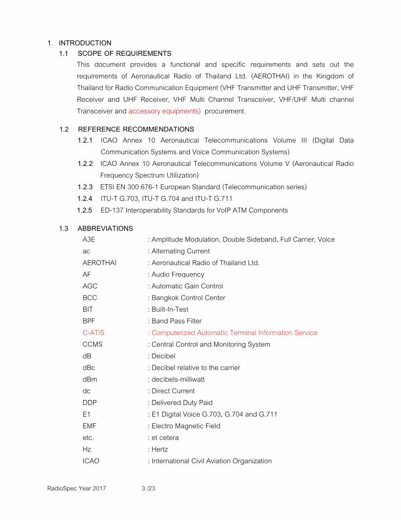
1. INTRODUCTION
1.1 SCOPE OF REQUIREMENTS
This document provides a functional and specific requirements and sets out the requirements of Aeronautical Radio of Thailand Ltd. (AEROTHAI) in the Kingdom of Thailand for Radio Communication Equipment (VHF Transmitter and UHF Transmitter, VHF Receiver and UHF Receiver, VHF Multi Channel Transceiver, VHF/UHF Multi channel Transceiver and accessory equipments) procurement.
1.2 REFERENCE RECOMMENDATIONS
1.2.1 ICAO Annex 10 Aeronautical Telecommunications Volume III (Digital Data Communication Systems and Voice Communication Systems)
1.2.2 ICAO Annex 10 Aeronautical Telecommunications Volume V (Aeronautical Radio Frequency Spectrum Utilization)
1.2.3 ETSI EN 300 676-1 European Standard (Telecommunication series) 1.2.4 ITU-T G.703, ITU-T G.704 and ITU-T G.711
1.2.5 ED-137 Interoperability Standards for VoIP ATM Components
1.3 ABBREVIATIONS
A3E : Amplitude Modulation, Double Sideband, Full Carrier, Voice ac : Alternating Current AEROTHAI : Aeronautical Radio of Thailand Ltd. AF : Audio Frequency
AGC : Automatic Gain Control BCC : Bangkok Control Center BIT : Built-In-Test BPF : Band Pass Filter C-ATIS : Computerized Automatic Terminal Information Service
CCMS : Central Control and Monitoring System
dB : Decibel dBc : Decibel relative to the carrier dBm : decibels-milliwatt dc : Direct Current DDP : Delivered Duty Paid
E1 : E1 Digital Voice G.703, G.704 and G.711
EMF : Electro Magnetic Field
etc. : et cetera
Hz : Hertz ICAO : International Civil Aviation Organization

RadioSpec Year 2017 4 /23
ICD : Interface Control Document IF : Intermediate Frequency
KHz : Kilohertz
mA : Milliampere
MHz : Megahertz
ms : Millisecond
mV : Millivolt mW : Milliwatt NBTC : Office of The National Broadcasting and The Telecommunications Commission (NBTC) PTT : Push To Talk
ppm : part per million
RCMS : Remote control and monitoring system
RF : Radio Frequency
rms : root-mean-square
RX : Receiver S : Second
S+N/N : Signal plus Noise to Noise Ratio
SINAD : Signal plus Noise plus Distortion to Noise plus Distortion Ratio
SNMP : Simple Network Management Protocol SQ : Squelch
TCP/IP : Transmission Control Protocol /Internet Protocol THD : Total Harmonic Distortion
TRX : Transceiver TX : Transmitter UHF : Ultra High Frequency
Vac : Alternating Current Volt Vdc : Direct Current Volt VDL : VHF Digital Link
VHF : Very High Frequency
VSWR : Voltage Standing Wave Ratio W : Watt CTR TWR : Chiang Rai Tower MHS TWR : Mae Hong Son Tower LPN TWR : Lampang Tower MST TWR : Mae Sot Tower PAE TWR : Phrae Tower
RadioSpec Year 2017 5 /23
NAN TWR : Nan Tower PCB TWR : Phetchabun Tower UDN TWR : Udonthani Tower LOI TWR : Loei Tower NKP TWR : Nakonphanom Tower SKN TWR : Sakhonnakhon Tower KKN TWR : Khonkaen Tower NKR TWR : Nakhonratchasima Tower BUR TWR : Buriram Tower UBL TWR : Ubonratchathani Tower ROI TWR : Roi Et Tower SVB TWR : Suvarnabhumi Tower HHN TWR : Hua Hin Tower CPN TWR : Chumphon Tower RAN TWR : Ranong Tower NTW TWR : Narathiwat Tower MK BACC : Tungmahamek Bangkok Area Control Center PUT TWR : Phuket Tower KBI TWR : Krabi Tower HTY TWR : Hat Yai Tower TRN TWR : Trang Tower PTN TWR : Pattani Tower
RadioSpec Year 2017 6 /23
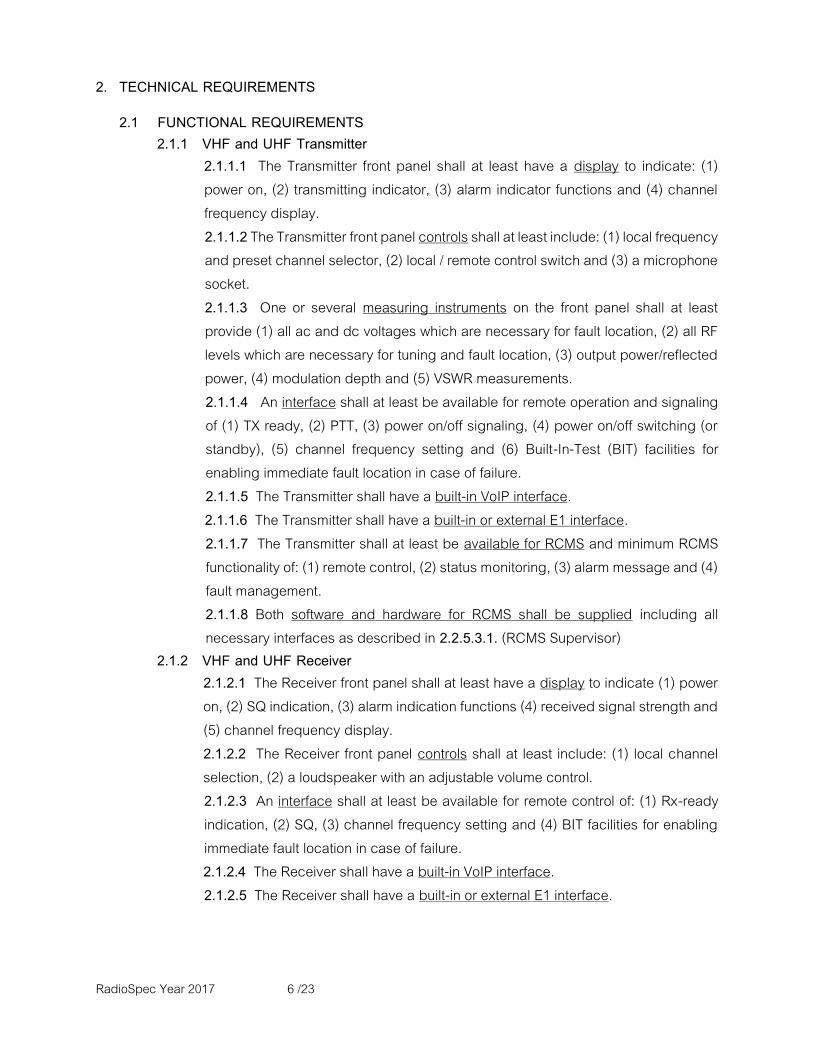
2. TECHNICAL REQUIREMENTS
2.1 FUNCTIONAL REQUIREMENTS
2.1.1 VHF and UHF Transmitter 2.1.1.1 The Transmitter front panel shall at least have a display to indicate: (1) power on, (2) transmitting indicator, (3) alarm indicator functions and (4) channel frequency display. 2.1.1.2 The Transmitter front panel controls shall at least include: (1) local frequency and preset channel selector, (2) local / remote control switch and (3) a microphone socket.
2.1.1.3 One or several measuring instruments on the front panel shall at least provide (1) all ac and dc voltages which are necessary for fault location, (2) all RF levels which are necessary for tuning and fault location, (3) output power/reflected power, (4) modulation depth and (5) VSWR measurements. 2.1.1.4 An interface shall at least be available for remote operation and signaling of (1) TX ready, (2) PTT, (3) power on/off signaling, (4) power on/off switching (or standby), (5) channel frequency setting and (6) Built-In-Test (BIT) facilities for enabling immediate fault location in case of failure.
2.1.1.5 The Transmitter shall have a built-in VoIP interface.
2.1.1.6 The Transmitter shall have a built-in or external E1 interface. 2.1.1.7 The Transmitter shall at least be available for RCMS and minimum RCMS functionality of: (1) remote control, (2) status monitoring, (3) alarm message and (4) fault management.
2.1.1.8 Both software and hardware for RCMS shall be supplied including all necessary interfaces as described in 2.2.5.3.1. (RCMS Supervisor)
2.1.2 VHF and UHF Receiver 2.1.2.1 The Receiver front panel shall at least have a display to indicate (1) power on, (2) SQ indication, (3) alarm indication functions (4) received signal strength and (5) channel frequency display.
2.1.2.2 The Receiver front panel controls shall at least include: (1) local channel selection, (2) a loudspeaker with an adjustable volume control.
2.1.2.3 An interface shall at least be available for remote control of: (1) Rx-ready indication, (2) SQ, (3) channel frequency setting and (4) BIT facilities for enabling immediate fault location in case of failure.
2.1.2.4 The Receiver shall have a built-in VoIP interface.
2.1.2.5 The Receiver shall have a built-in or external E1 interface.
RadioSpec Year 2017 7 /23
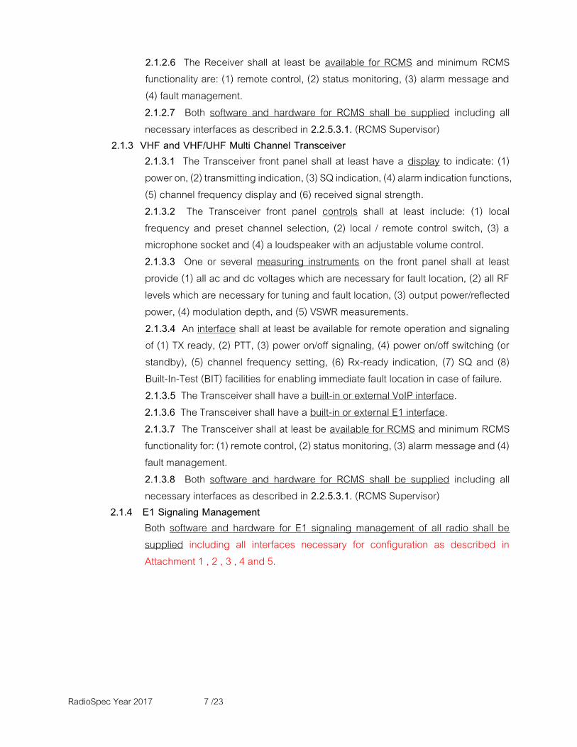
2.1.2.6 The Receiver shall at least be available for RCMS and minimum RCMS functionality are: (1) remote control, (2) status monitoring, (3) alarm message and (4) fault management. 2.1.2.7 Both software and hardware for RCMS shall be supplied including all necessary interfaces as described in 2.2.5.3.1. (RCMS Supervisor)
2.1.3 VHF and VHF/UHF Multi Channel Transceiver 2.1.3.1 The Transceiver front panel shall at least have a display to indicate: (1) power on, (2) transmitting indication, (3) SQ indication, (4) alarm indication functions, (5) channel frequency display and (6) received signal strength. 2.1.3.2 The Transceiver front panel controls shall at least include: (1) local frequency and preset channel selection, (2) local / remote control switch, (3) a microphone socket and (4) a loudspeaker with an adjustable volume control. 2.1.3.3 One or several measuring instruments on the front panel shall at least provide (1) all ac and dc voltages which are necessary for fault location, (2) all RF levels which are necessary for tuning and fault location, (3) output power/reflected power, (4) modulation depth, and (5) VSWR measurements. 2.1.3.4 An interface shall at least be available for remote operation and signaling of (1) TX ready, (2) PTT, (3) power on/off signaling, (4) power on/off switching (or standby), (5) channel frequency setting, (6) Rx-ready indication, (7) SQ and (8) Built-In-Test (BIT) facilities for enabling immediate fault location in case of failure. 2.1.3.5 The Transceiver shall have a built-in or external VoIP interface. 2.1.3.6 The Transceiver shall have a built-in or external E1 interface.
2.1.3.7 The Transceiver shall at least be available for RCMS and minimum RCMS functionality for: (1) remote control, (2) status monitoring, (3) alarm message and (4) fault management. 2.1.3.8 Both software and hardware for RCMS shall be supplied including all necessary interfaces as described in 2.2.5.3.1. (RCMS Supervisor)
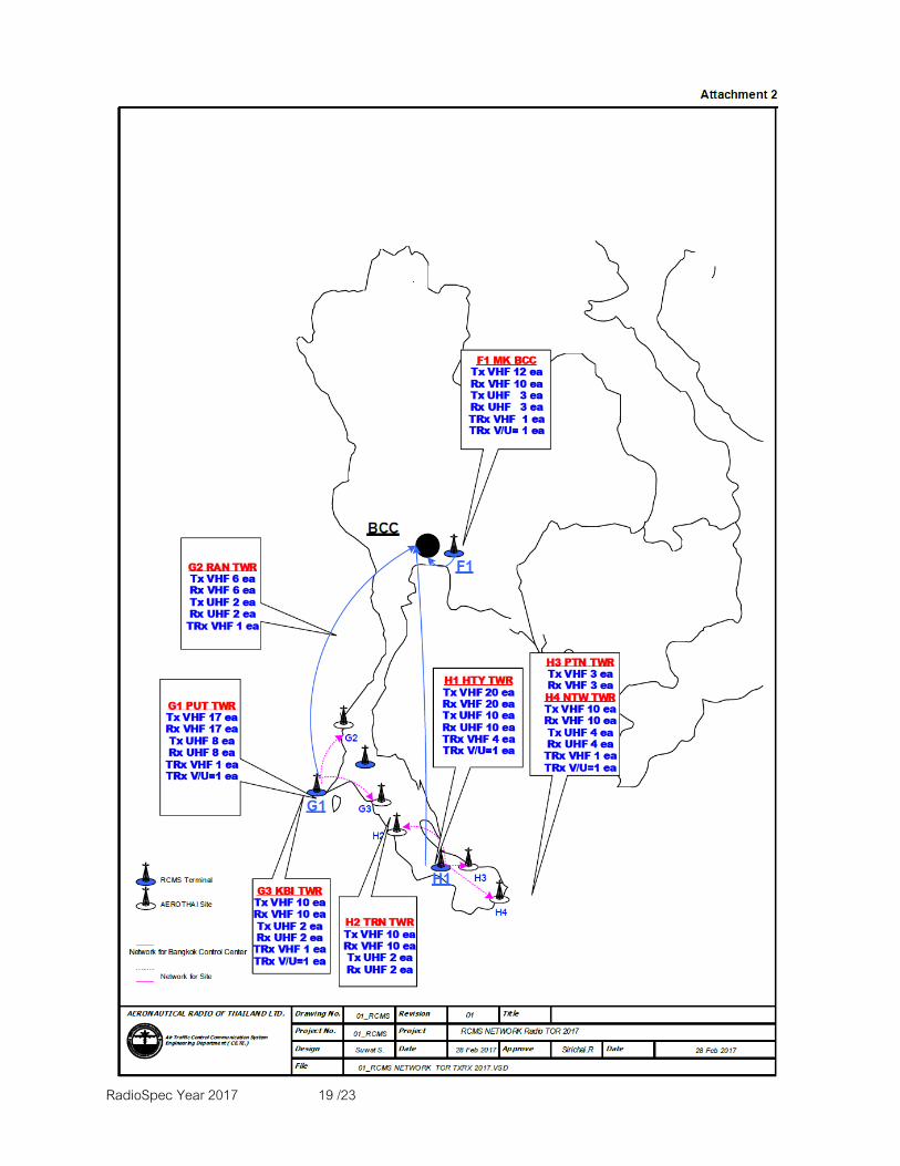
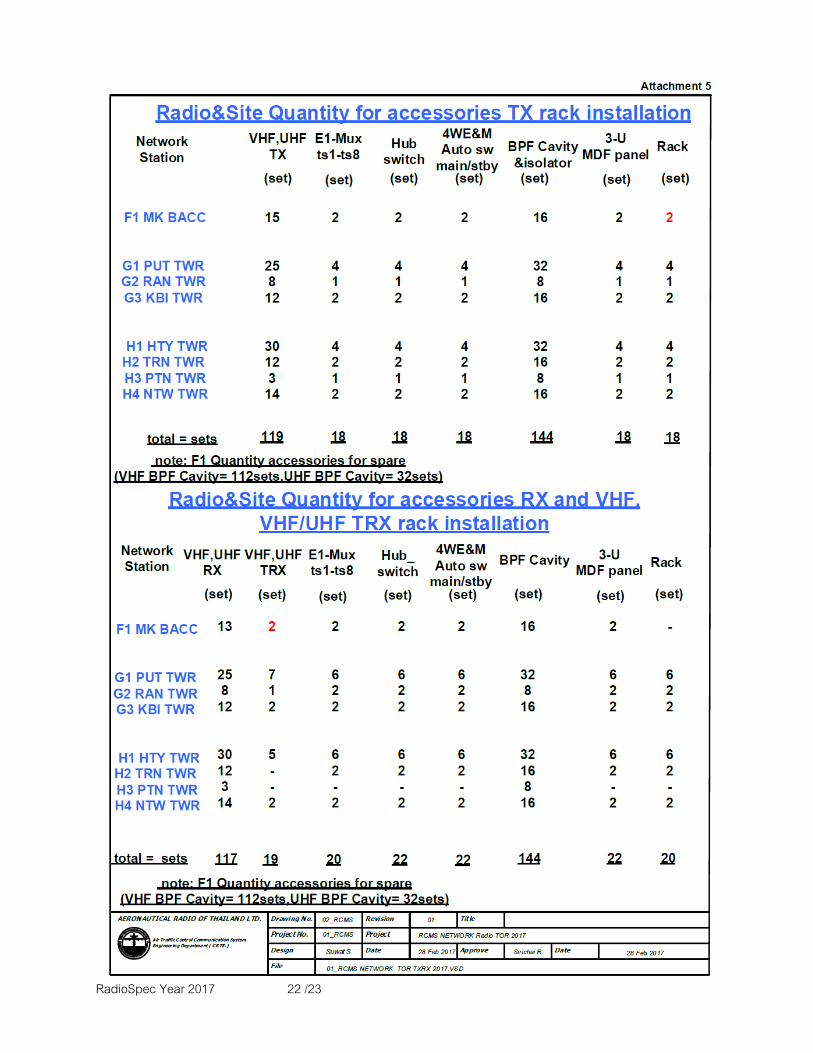
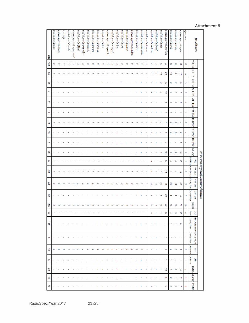
2.1.4 E1 Signaling Management Both software and hardware for E1 signaling management of all radio shall be supplied including all interfaces necessary for configuration as described in Attachment 1 , 2 , 3 , 4 and 5.
RadioSpec Year 2017 8 /23
2.2 SPECIFIC REQUIREMENTS
2.2.1 VHF and UHF Transmitter The following specifications are used as specifications for both VHF and UHF Transmitters unless specified individually. 2.2.1.1 RF Characteristics
2.2.1.1.1 Frequency Range and Channel Spacing
2.2.1.1.1.1 The VHF Transmitter shall be tunable over the range of 118 to 136.975 MHz without any change of elements. 2.2.1.1.1.2 The UHF Transmitter shall be tunable over the range of 225 to 399.975 MHz without any change of elements. 2.2.1.1.1.3 The channel spacing for the VHF Transmitter shall be selectable between 8.33 KHz and 25 KHz without any change of elements. 2.2.1.1.1.4 The channel spacing for the UHF Transmitter shall be 25 KHz. 2.2.1.1.2 Frequency Oscillator 2.2.1.1.2.1 The Transmitter shall be a single channel, synthesizer oscillator. 2.2.1.1.2.2 The frequency error shall be within ±1 ppm over the range of 118 to 136.975 MHz for VHF Transmitter and 225 to 399.975 MHz for UHF Transmitter under the environmental conditions as specified in paragraph 2.2.5.1. (Environment) 2.2.1.1.3 Modulation
2.2.1.1.3.1 VHF transmitter’s emission type shall be Double Side Band Amplitude Modulation A3E for speech and data that comply with VDL mode 2.
2.2.1.1.3.2 UHF transmitter’s emission type shall be Double Side Band Amplitude Modulation A3E for speech.
2.2.1.1.3.3 The Tenderer shall supply with software for A3E and VDL mode 2 installed in the VHF Transmitters. The Transmitters shall include all interfaces for speech and VDL modes and the selection of mode shall be selected by the software without any need to replace/modify or re-configure the hardware.
2.2.1.1.3.4 The modulation depth shall be adjustable up to 85 % or greater.
2.2.1.1.4 Output Characteristics
2.2.1.1.4.1 The carrier power output delivered into a 50 OHM load shall be greater than or equal to 30 W continuous. 2.2.1.1.4.2 The carrier output power shall be adjustable to the required preset lower limit and upper limit.
RadioSpec Year 2017 9 /23
2.2.1.1.4.3 The second harmonics of the carrier frequency shall not exceed -36 dBm. 2.2.1.1.4.4 A limiter shall ensure that the maximum modulation depth not exceed 95 %. 2.2.1.1.4.5 Protection against mismatch output impedance shall be provided and any mismatch shall not cause the RF output damage. 2.2.1.1.4.6 Spurious Output shall be lower than the carrier frequency at least 70 dBc.
2.2.1.2 AF and Push to Talk Contact Characteristics
2.2.1.2.1 The AF input shall be designed for 600 OHM balanced, and a level between – 30 dBm and +10 dBm. 2.2.1.2.2 The 3 dB AF bandwidth shall be 300 Hz to 3.4 kHz (for 25 kHz channel spacing) and 350 Hz to 2.5 kHz (for 8.33 kHz channel spacing). 2.2.1.2.3 The Total Harmonic Distortion (THD) shall be less than 10 % measured with 1 kHz test tone at 90% modulation depth. 2.2.1.2.4 Local operation shall be provided by means of a microphone with a push to talk (PTT) input.
2.2.2 VHF and UHF Receiver The following specifications are used as specifications for both VHF and UHF Receivers except when specified individually. 2.2.2.1 RF Characteristics
2.2.2.1.1 Frequency Range and Channel Spacing
2.2.2.1.1.1 The VHF Receiver shall be tunable over the range of 118 to 136.975 MHz without any change of elements.
2.2.2.1.1.2 The UHF Receiver shall be tunable over the range of 225 to 399.975 MHz without any change of elements.
2.2.2.1.1.3 The channel spacing for the VHF Receiver shall be selectable between 8.33 kHz and 25 kHz without any change of elements. 2.2.2.1.1.4 The UHF Receiver channel spacing shall be 25 kHz. 2.2.2.1.2 Frequency Oscillator
2.2.2.1.2.1 The Receiver’s frequency oscillator shall be the single channel, synthesizer oscillator. 2.2.2.1.2.2 The frequency error shall be within ± 1 ppm over the range of 118 to 136.975 MHz for VHF Receiver and 225 to 399.975 MHz for UHF Receiver under the environmental conditions as specified in paragraph 2.2.5.1. (Environment) 2.2.2.1.3 Demodulation

RadioSpec Year 2017 10 /23
2.2.2.1.3.1 VHF Receiver’s reception type shall be Double Side Band Amplitude Modulation, A3E for speech and data that comply with VDL mode 2.
2.2.2.1.3.2 UHF Receiver’s reception type shall be Double Side Band Amplitude Modulation, A3E for speech. 2.2.2.1.3.3 The Tenderer shall supply the software for A3E, VDL mode 2 installed in the VHF receivers. The receivers shall include all interfaces for speech and VDL mode 2 and the selection of mode shall be selected by the software without any need to replace/modify or re-configure the hardware.
2.2.2.1.4 RF Input Characteristics
2.2.2.1.4.1 The input impedance shall be 50 OHM. 2.2.2.1.4.2 The VSWR shall be better than 2:1 at the tuned frequency. 2.2.2.1.4.3 The sensitivity shall be less than or equal to -107 dBm (VHF) and less than or equal to -101 dBm (UHF) for a SINAD at the receiver output 12 dB at least for an input signal modulated 30 % at 1 KHz. (ITU-T P.53 weighted) 2.2.2.1.4.4 The audio output level variation shall not exceed 3 dB for the RF input level from –107 dBm to +7 dBm (VHF) and -101 dBm to +1 dBm (UHF).
2.2.2.1.4.5 The permissible input voltage without causing damage shall at least be +25 dBm independently of the signal frequency. 2.2.2.1.4.6 The spurious response rejection shall be at least 70 dB. 2.2.2.1.4.7 The image response rejection shall at least be 70 dB. 2.2.2.1.4.8 The IF Response Rejection shall at least be 70 dB. 2.2.2.1.4.9 The selectivity shall at least be 70 dB at ± 25 kHz from channel frequency. 2.2.2.1.4.10 A pre-set SQ control shall be provided to cover the range from -107 dBm to -77.5 dBm (VHF) and -101 dBm to -77.5 dBm (UHF).
2.2.2.2 AF and Squelch Contact Characteristics
2.2.2.2.1 The audio output shall be provided by means of a balanced 600 ohm transformer and a level adjustable over the range -30 dBm to +10 dBm. 2.2.2.2.2 The audio output level shall vary less than or equal to ±2 dB with 1 KHz 30 % and 90 % modulated. 2.2.2.2.3 The 3 dB AF bandwidth shall be 300 Hz to 3.4 kHz (for 25 kHz channel spacing) and 350 Hz to 2.5 kHz (for 8.33 kHz channel spacing).
RadioSpec Year 2017 11 /23
2.2.2.2.4 The THD shall not exceed 5 % at 0 dBm audio output with RF input between -47 dBm and -7 dBm 90 % modulated at 1 kHz. 2.2.2.2.5 The ratio of (S+N)/N shall be greater or equal to 45 dB at 0 dBm audio output with RF input between -47 dBm and -7 dBm 80 % modulated at 1 kHz. 2.2.2.2.6 A SQ contact shall be available.
2.2.3 VHF Multi Channel Transceiver 2.2.3.1 General
2.2.3.1.1 The Multi Channel Transceiver shall be tunable over the range of 118 to 136.975 MHz without any change of elements. 2.2.3.1.2 The channel spacing shall be 25 KHz. 2.2.3.1.3 The tuning increment shall be made on the step of 25 kHz or less. 2.2.3.1.4 The frequency error shall be within ± 1ppm over the range of VHF band under the environmental conditions as specified in paragraph 2.2.5.1. (Environment) 2.2.3.1.5 The type of emission and reception shall be Double Side Band Amplitude Modulation (A3E) for speech. 2.2.3.1.6 A pre-selection channel shall at least consist of 10 channels. 2.2.3.1.7 The Transceiver shall include a handset and a headset for local operation and a set of interfacing. 2.2.3.1.8 The Transceiver shall include a remote control unit for remote operation.
2.2.3.2 Receiver Characteristics
2.2.3.2.1 The sensitivity shall be less than or equal to -105 dBm for 12dB (SINAD) with 30 % modulation at 1 kHz (ITU-T P.53 weighted). 2.2.3.2.2 The Input impedance shall be 50 OHM. 2.2.3.2.3 Image response shall at least be 70 dB. 2.2.3.2.4 Spurious response shall at least be 70 dB. 2.2.3.2.5 Audio response shall be in the frequency band from 300 Hz to 3.4 kHz or wider. 2.2.3.2.6 The audio output shall be provided by means of a balanced 600 ohms transformer. 2.2.3.2.7 A pre-set SQ control shall be provided to cover the range from -107 dBm to -77.5 dBm.
2.2.3.3 Transmitter Characteristics
RadioSpec Year 2017 12 /23
2.2.3.3.1 The carrier power output delivered into a 50 OHM load shall be greater than or equal to 30 W continuous.
2.2.3.3.2 Spurious Output shall be lower than the carrier frequency at least 70 dBc. 2.2.3.3.3 The second harmonics of the carrier frequency shall not exceed -36 dBm.
2.2.4 VHF/UHF Multi Channel Transceiver 2.2.4.1 General
2.2.4.1.1 The Multi Channel Transceiver shall be tunable over the range of 118 to 136.975 MHz for VHF band without any change of elements. 2.2.4.1.2 The Multi Channel Transceiver shall be tunable over the range of 225 to 399.975 MHz for UHF band without any change of elements. 2.2.4.1.3 The channel spacing shall be 8.33 KHz, 25 kHz for VHF band and 25 kHz for UHF band. 2.2.4.1.4 The frequency error shall be within ± 1ppm over the range of VHF band and UHF band under the environmental conditions as specified in paragraph 2.2.5.1. (Environment) 2.2.4.1.5 The type of emission and reception shall be Double Side Band Amplitude Modulation (A3E) for speech. 2.2.4.1.6 A minimum pre-selection shall consist of 10 channels.
2.2.4.2 Receiver Characteristics
2.2.4.2.1 The sensitivity shall be less than or equal to -99 dBm for a SINAD at the receiver output 12 dB at least for an input signal modulated 30 % at 1 KHz. (ITU-T P.53 weighted) 2.2.4.2.2 Input impedance shall be 50 OHM. 2.2.4.2.3 Image response shall at least be 70 dB. 2.2.4.2.4 Spurious response shall at least be 70 dB. 2.2.4.2.5 Audio response shall be in the frequency band from 300 Hz to 3.4 kHz or wider. 2.2.4.2.6 The receiver shall have a built-in VHF/UHF (121.5/243.0 MHz) guard receiver.
2.2.4.3 Transmitter Characteristics
2.2.4.3.1 The carrier power output delivered into a 50 OHM load shall be greater than or equal to 30 W continuous. 2.2.4.3.2 Spurious Output shall be lower than carrier frequency at least 70 dBc.

RadioSpec Year 2017 13 /23
2.2.4.3.3 The second harmonics of the carrier frequency shall not exceed -36 dBm.
2.2.5 Supporting System
The word “radio equipment” in this section is referring to VHF and UHF Receiver, VHF and UHF Transmitter, VHF Multi Channel Transceiver and VHF/UHF Multi Channel Transceiver.
2.2.5.1 Environment Conditions
All radio equipment shall be able to operate in a controlled environment of approximately 10-45 degree Celsius and relative humidity up to 70 %. 2.2.5.2 Power Supply
2.2.5.2.1 VHF and UHF Receiver, VHF and UHF Transmitter. 2.2.5.2.1.1 The power supply of all equipment shall be designed for using with 210-230 Vac. 50 Hz. 2.2.5.2.1.2 The power supply shall be capable of operating with the 24 Vdc. float charged batteries system. 2.2.5.2.1.3 All equipment shall be automatically switched to dc power when ac power failure without any interruption to the operation of equipment. 2.2.5.2.2 VHF and VHF/UHF Multi Channel Transceiver 2.2.5.2.2.1 The power supply of all equipment shall be designed for using with 210-230 Vac. 50 Hz. 2.2.5.2.2.2 The power supply shall be capable of operating with the 24 Vdc. float charged batteries system. 2.2.5.2.2.3 All equipment shall automatically switched to dc power when ac power failure occurs without any interruption to the operation of equipment. 2.2.5.2.2.4 Nineteen (19) sets of 24 Vdc power system for VHF and VHF/UHF Multi Channel Transceiver shall be provided, consisting of (1) two (2) pieces of 12V 100Ah sealed-lead rechargeable batteries, (2) a 24V 100A charger (3) a 24V 1500W inverter with ATS (Automatic Transfer Switch) included and (4) Twenty (20) meters, at minimum, of DC cable red and black color 16 sq.mm. with cable lugs. The Charger and Inverter can be controlled and monitored using the Simple Network Management Protocol (SNMP) and both can PC run RCMS management.
2.2.5.3 Accessories

RadioSpec Year 2017 14 /23
2.2.5.3.1 The Tenderer shall provide RCMS supervisor software and radio diagnostic software for maintenance, repair and configuration for all VHF and UHF Receivers, VHF and UHF Transmitters, VHF Multi Channel Transceivers, VHF/UHF Multi Channel Transceivers. Both hardware and software (with licenses) for RCMS shall be supplied including all interfaces necessary for configuration as described in Attachment 1, 2 , 3 , 4 and 5. 2.2.5.3.2 All VHF and UHF Receivers, VHF and UHF Transmitters, VHF Multi Channel Transceivers, VHF/UHF Multi Channel Transceivers can be controlled and monitored using the Simple Network Management Protocol (SNMP),and can run on RCMS database server. 2.2.5.3.3 Controlling and Monitoring function shall consist of the following capabilities at the minimum: Power on status monitoring. Transmitting status monitoring. Alarm status monitoring. Operational channel frequency monitoring. Enable/Disable Transmitting/Receiving setting. Frequency setting. RF power setting. Squelch level setting. 2.2.5.3.4 All Radio shall be connected with CCMS (provided by AEROTHAI) to send and receive information as specified in 2.2.5.3.3. 2.2.5.3.5 The Tenderer shall provide and detail the Radio–CCMS information exchange. 2.2.5.3.6 The Tenderer shall provide and detail the mechanism to provide data integrity and security against unauthorized access, intrusion and malicious computer attacks. 2.2.5.3.7 The Tenderer shall provide a list of all necessary standards documents and ICD with regards to the Radio–CCMS information exchange. 2.2.5.3.8 The Tenderer shall provide Two hundred seventy (270) sets of VHF single cavity filter with horizontal installation not exceed 60 cm. depth of standard 19” rack and one hundred sixty (160) of RF isolator with 50 watts dummy load. 2.2.5.3.9 The Tenderer shall provide Sixty-two (62) sets of UHF single cavity filter with horizontal installation not exceed 60 cm. depth of standard 19” rack and fourty (40) sets of RF isolator with 50 watts dummy load.

RadioSpec Year 2017 15 /23
2.2.5.3.10 The Tenderer shall provide (1) a handset for local operation, (2) a set of interfacing connectors, (3) VoIP ED137B remote control unit shall be able to adjust a frequency. It shall be equipped with a headset or handset, and (4) a base station antenna, (5) a set of VHF dual auto-tune cavity filter, (6) ED137B converter to 4WE&M for each VHF Multi Channel Transceiver. 2.2.5.3.11 The Tenderer shall provide (1) a handset for local operation, (2) a set of interfacing connectors, (3) VoIP ED137B remote control unit shall be able to adjust a frequency. It shall be equipped with a headset or handset, (4) a base station antenna and (5) a set of VHF/UHF dual auto-tune cavity filter, (6) ED137B converter to 4WE&M for each VHF/UHF Multi Channel Transceiver. 2.2.5.3.12 All VHF and UHF Receivers, VHF and UHF Transmitters, VHF Multi Channel Transceivers, VHF/UHF Multi Channel Transceivers shall be standard 19" rack mounted size and shall include slides suitable for mounting and maintenance, and all hardware necessary to permit fitting into a standard 19" rack. 2.2.5.3.13 The Tenderer shall provide sixty (60) racks (42-U 600X800 standard 19") 2.2.5.3.14 The Tenderer shall provide sixty (60) sets of programmable hub switch 16-port with 1-SFP module per set (with cable managements 1U height). 2.2.5.3.15 The Tenderer shall provide sixty (60) sets of 24-RJ45 Patch Panel (1U height) and MDF Krone panel (3U height) , with 15-disconnected Krone type per MDF panel and five-hundred (500) meters 0.4 sq.mm. Cross cable red-white color. 2.2.5.3.16 The Tenderer shall provide spare AC&DC fuses for all equipments. 2.2.5.3.17 The Tenderer shall provide five-hundred (500)meters of DC cable and DC connector for all equipment DC cable 2-core copper 2.5 sq.mm. 2.2.5.3.18 The Tenderer shall provide five-hundred (500)meter AC cable and AC connector for all equipment AC cable 3-core copper 1.0 sq.mm. 2.2.5.3.19 The Tenderer shall provide of accessories comprising: • Five hundred (500) meters for Telephone cable TIVE 4C size 0.65
sq.mm. for wiring all radio installation.
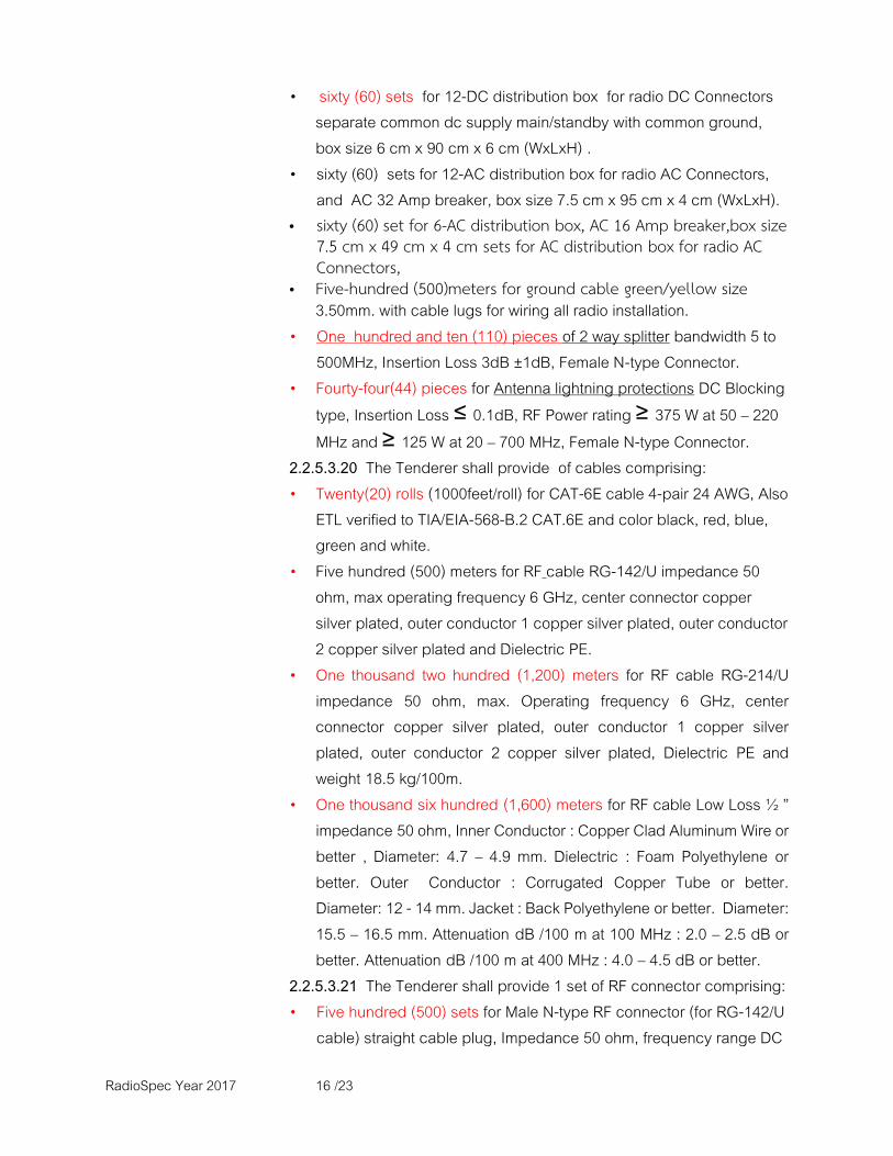
RadioSpec Year 2017 16 /23
• sixty (60) sets for 12-DC distribution box for radio DC Connectors separate common dc supply main/standby with common ground, box size 6 cm x 90 cm x 6 cm (WxLxH) .
• sixty (60) sets for 12-AC distribution box for radio AC Connectors, and AC 32 Amp breaker, box size 7.5 cm x 95 cm x 4 cm (WxLxH).
• sixty (60) set for 6-AC distribution box, AC 16 Amp breaker,box size 7.5 cm x 49 cm x 4 cm sets for AC distribution box for radio AC Connectors,
• Five-hundred (500)meters for ground cable green/yellow size 3.50mm. with cable lugs for wiring all radio installation.
• One hundred and ten (110) pieces of 2 way splitter bandwidth 5 to 500MHz, Insertion Loss 3dB ±1dB, Female N-type Connector.
• Fourty-four(44) pieces for Antenna lightning protections DC Blocking type, Insertion Loss ≤ 0.1dB, RF Power rating ≥ 375 W at 50 – 220 MHz and ≥ 125 W at 20 – 700 MHz, Female N-type Connector.
2.2.5.3.20 The Tenderer shall provide of cables comprising: • Twenty(20) rolls (1000feet/roll) for CAT-6E cable 4-pair 24 AWG, Also
ETL verified to TIA/EIA-568-B.2 CAT.6E and color black, red, blue, green and white.
• Five hundred (500) meters for RF cable RG-142/U impedance 50 ohm, max operating frequency 6 GHz, center connector copper silver plated, outer conductor 1 copper silver plated, outer conductor 2 copper silver plated and Dielectric PE.
• One thousand two hundred (1,200) meters for RF cable RG-214/U impedance 50 ohm, max. Operating frequency 6 GHz, center connector copper silver plated, outer conductor 1 copper silver plated, outer conductor 2 copper silver plated, Dielectric PE and weight 18.5 kg/100m.
• One thousand six hundred (1,600) meters for RF cable Low Loss ½ ” impedance 50 ohm, Inner Conductor : Copper Clad Aluminum Wire or better , Diameter: 4.7 – 4.9 mm. Dielectric : Foam Polyethylene or better. Outer Conductor : Corrugated Copper Tube or better. Diameter: 12 - 14 mm. Jacket : Back Polyethylene or better. Diameter: 15.5 – 16.5 mm. Attenuation dB /100 m at 100 MHz : 2.0 – 2.5 dB or better. Attenuation dB /100 m at 400 MHz : 4.0 – 4.5 dB or better.
2.2.5.3.21 The Tenderer shall provide 1 set of RF connector comprising: • Five hundred (500) sets for Male N-type RF connector (for RG-142/U
cable) straight cable plug, Impedance 50 ohm, frequency range DC

RadioSpec Year 2017 17 /23
to 2GHz, return loss ≥ 26 dB, center contact crimped, outer contact crimped.
• Five hundred (500) sets for Female N-type RF connector (for RG-142/U) straight bulkhead cable feed through, impedance 50 ohm, frequency max. 11GHz, center contact crimped, outer contact crimped.
• Five hundred (500) sets for Male N-type RF connector (for RG-142/U cable) right angle cable feed through, impedance 50 ohm, frequency max 11 GHz, center contact soldering, outer contact crimped.
• Six hundred (600) sets for Male N-type RF connector (for RG-214/U cable) straight cable plug, Impedance 50 ohm, frequency range DC to 2GHz, return loss ≥ 30 dB, center contact crimped, outer contact crimped.
• Six hundred (600) sets for Male N-type RF connector (for Low Loss 1/2” cable) straight cable plug, Impedance 50 ohm. VSWR : ≤ 1.08 or better. Inner Conductor : Silver Plated or better. Outer Conductor : Silver Plated or better. Insulator : PTFE, FE, TPX ,PFA.
• Five hundred (500) sets for Male BNC RF connector (for RG-142/U cable) straight cable plug, Impedance 50 ohm, frequency range DC to 2GHz, center contact crimped, outer contact crimped.
• Five hundred (500) sets for Female N-type RF connector chassis mount round panel bulkhead, Impedance 50 ohm, frequency range DC to 2GHz.
• Five hundred (500) sets for Adapter Male N-type to Male N-type Impedance 50 ohm, frequency range DC to 1GHz.
• Five hundred (500) sets for Adapter Female N-type to Female N-type Impedance 50 ohm, frequency range DC to 1GHz.
2.2.5.3.22 The Tenderer shall provide One hundred (100) sets of Grounding Kit for Low Loss 1/2” Cable. Body : Stainless Steel or better. Contact Surface : Tin Plated Copper or better. Surge Current : ≥ 50 kA. Sealing Class : IP66. Cable length ≥ 30 cm. 2.2.5.3.23 The Tenderer shall provide Eight hundred (800) sets of Feeder Cable Clamp for Low Loss 1/2”. C Hanger Adapter : Stainless Steel angle Adapters Pressing Type or Better. Bolt : M8 or Bigger. Rod/Nut : Stainless Steel. Flat/Lock Washers : Stainless Steel. Plastic Clamp : Nylon UV or better. Single Hole Double Stack Feeder. Color : Black.

RadioSpec Year 2017 18 /23
RadioSpec Year 2017 19 /23

RadioSpec Year 2017 20 /23

RadioSpec Year 2017 21 /23
RadioSpec Year 2017 22 /23
RadioSpec Year 2017 23 /23
Attachment 6