radiographic analysis of lower limb axial · pdf fileh. abstract — high tibia osteotomy...
TRANSCRIPT
Abstract— High Tibia Osteotomy (HTO) is an operation that
requires full lower limb alignment assessment to plan bone cuts.
This study is trying to introduce a pre HTO operative
radiographic analysis method to improve measurement of the
whole lower limb using anatomical and mechanical axes and the
angles between them. The aim is to improve the reproducibility
of the measurements, and not personalize them. Using the
introduced method, the lower limb radiographic alignments of a
25 year old female patient with a varus knee deformity were
analyzed pre and post operation using imaging from hip to
ankle.
Index Terms— High Tibial Osteotomy, Radiography,
Alignment,
I. INTRODUCTION
The High Tibial Osteotomy (HTO) is an operation which
aims to re-establish the distribution of load on the articular
surface within the knee by cutting (osteotomizing) the
proximal (upper) part of the tibia (just distal to the tibial
plateau) and opening at the position of the cut to change the
lower limb geometry [1]. By performing this procedure, we
will be able to observe an unloading of the diseased joint
surface and therefore a loading onto the healthy surface of the
joint. In performing this procedure it is important to prevent
the obvious postoperative complications [2] and loss of
correction [3]. In the preoperative planning for HTO surgery,
lower limb anatomical and mechanical axes and the angles
between the femur and the tibia have to be measured before
the preceding to surgery [4]. The lower limb alignment is
generally assessed two-dimensionally (2D) using gray scale
radiographic images of the whole lower limb. The
Manuscript received January 15, 2013; revised April 05, 2013. All of the
authors have no financial relationship to any private companies and
organizations.
Adrien Durandet is with the National Engineering School of Metz (ENIM), Metz, France and the School of Design and Engineering, Brunel
University West London, UK
Pierre-Louis Ricci is with the National Engineering School of Metz (ENIM), Metz, France and the School of Design and Engineering, Brunel
University West London, UK
Amir Hossein Saveh is with the Shahid Beheshti University of Medical Sciences, Akhtar Orthopaedic Research Centre, Tehran, Iran
Qureish Vanat is with the Queen Elizabeth Hospital, Woolwich, UK
Bin Wang is with the School of Design and Engineering, Brunel University West London, UK
Ibrahim Esat is with the School of Design and Engineering, Brunel
University West London, UK Mahmoud Chizari is with Orthopaedic Learning and Research Center at
Brunel University West London, UK, (corresponding author: Mahmoud
Chizari. Phone: +447886454320; e-mail: [email protected]).
Hip-Knee-Ankle angle or tibio-femoral angle is important
measurement to assess the varus or valgus deformity of the
knee [5]. Postoperative alignment in Opening Wedge HTO
depends on an accurate preoperative plan and a meticulous
intraoperative technique [6].
Although software, like mediCAD® or PreOPlan
® are
used to assess the lower limb alignment, there is no accurate
method to define the beginning and end points of the axis and
existing methods are based on assumptions that may vary
from person to person. As an example, Pape and Rupp [7]
define the mechanicals axis of the femur by assimilating the
femoral head as a circle. The center of the circle assumes the
starting reference point. The next reference point is assigned
to the center of the knee, which can be found at the mid-point
of a line connecting the tibial spines. In severe osteoarthritis
with subluxated knee joint, two separate middle points of the
tibia and femur need to be established. A perpendicular line
to the subchondral joint of both proximal tibia and distal
femur is drawn with the middle point being half-way from
medial to lateral end of the line. The center of the tibio-talar
joint is the midpoint of the talar width and the midpoint of the
talar height.
To find others points Moreland et al. [2] identified five
points which may be considered as the centers of the knee:
the femoral notch, the tibial spines, the femoral condyles, the
soft tissue and the tibia plateau. Furthermore, they identified
three points for the ankle: centers of the bones, the soft tissue
and the talus.
To draw the mechanicals axis, the reference points should
be connected using lines. The mechanical axis of the femur is
drawn by connecting the center of the knee with the center of
the femoral head. The mechanical axis of the tibia is drawn
by connecting the center of the knee with the center of the
ankle. Another important line is the Weight-Bearing Line
(WBL) which starts from the center of the femoral head and
ends to the center of the ankle.
Aim of the study
The aim of this study is to introduce a new method to
analyze full lower limb radiographic images and to define
accurately the anatomical/mechanical axes on it. The method
will also be used to examine the lower limb alignments of a
subject patient with varus deformity pre and post HTO
surgery for the assessment of the procedure.
II. METHODS
In this study the following methods are introduced to
define reference points and therefore axes of the lower limb.
Radiographic Analysis of Lower Limb Axial
Alignments
Adrien Durandet, Pierre-Louis Ricci, Amir Hossein Saveh, Qureish Vanat, Bin Wang, Ibrahim Esat,
Mahmoud Chizari
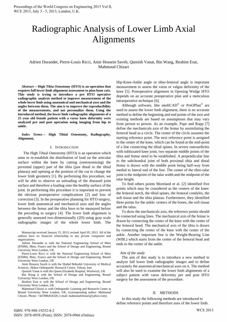
Proceedings of the World Congress on Engineering 2013 Vol II, WCE 2013, July 3 - 5, 2013, London, U.K.
ISBN: 978-988-19252-8-2 ISSN: 2078-0958 (Print); ISSN: 2078-0966 (Online)
WCE 2013
We will see how to find the references point of the femur and
the tibia.
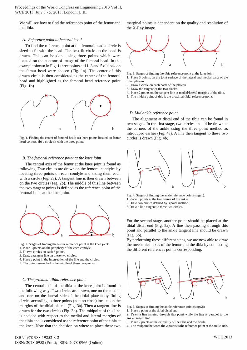
A. Reference point at femoral head
To find the reference point at the femoral head a circle is
sized to fit with the head. The best fit circle on the head is
drawn. This can be done using three points which were
located on the contour of image of the femoral head. In the
example shown in Fig. 1 three points at 11, 3 and 5 o’clock on
the femur head were chosen (Fig. 1a). The center of this
drawn circle is then considered as the center of the femoral
head and highlighted as the femoral head reference point
(Fig. 1b).
a b
Fig. 1. Finding the center of femoral head; (a) three points located on femur
head corners, (b) a circle fit with the three points
B. The femoral reference point at the knee joint
The central axis of the femur at the knee joint is found as
following. Two circles are drawn on the femoral condyles by
locating three points on each condyle and sizing them each
with a circle (Fig. 2a). A tangent line is then drawn between
on the two circles (Fig. 2b). The middle of this line between
the two tangent points is defined as the reference point of the
femoral bone at the knee joint.
a b
Fig. 2. Stages of finding the femur reference point at the knee joint:
1. Place 3 points on the periphery of the each condyle.
2. Fit two circles on each 3 points. 3. Draw a tangent line on these two circles.
4. Place a point in the intersection of the line and the circles.
5. The point researched is the middle of these two points.
C. The proximal tibial reference point
The central axis of the tibia at the knee joint is found in
the following way. Two circles are drawn, one on the medial
and one on the lateral side of the tibial plateau by fitting
circles according to three points (not too close) located on the
margins of the tibial plateau (Fig. 3a). Then a tangent line is
drawn for the two circles (Fig. 3b). The midpoint of this line
is decided with respect to the medial and lateral margins of
the tibia and is considered as the reference point of the tibia at
the knee. Note that the decision on where to place these two
marginal points is dependent on the quality and resolution of
the X-Ray image.
a b
Fig. 3. Stages of finding the tibia reference point at the knee joint:
1. Place 3 points, on the joint surface of the lateral and medial parts of the tibial plateau.
2. Draw a circle on each parts of the plateau.
3. Draw the tangent of the two circles. 4. Place 2 points on the tangent line at medial/lateral margins of the tibia.
5. The middle point of this is the proximal tibial reference point.
D. Mid ankle reference point
The alignment at distal end of the tibia can be found in
two stages. In the first stage, two circles should be drawn at
the corners of the ankle using the three point method as
introduced earlier (Fig. 4a). A line then tangent to these two
circles is drawn (Fig. 4b).
a b
Fig. 4. Stages of finding the ankle reference point (stage1): 1. Place 3 points at the two corner of the ankle.
2. Draw two circles defined by 3 point method.
3. Draw a line tangent to these two circles.
For the second stage, another point should be placed at the
tibial distal end (Fig. 5a). A line then passing through this
point and parallel to the ankle tangent line should be drawn
(Fig. 5b).
By performing these different steps, we are now able to draw
the mechanical axes of the femur and the tibia by connecting
the different references points corresponding.
a b
Fig. 5. Stages of finding the ankle reference point (stage2):
1. Place a point at the tibial distal end. 2. Draw a line passing through this point while the line is parallel to the
ankle tangent line.
3. Place 2 points at the extremity of the tibia and the fibula. 4. The midpoint between the 2 points is the reference point at the ankle side.
B
Fig. 2.B : Bottom of Femur
Proceedings of the World Congress on Engineering 2013 Vol II, WCE 2013, July 3 - 5, 2013, London, U.K.
ISBN: 978-988-19252-8-2 ISSN: 2078-0958 (Print); ISSN: 2078-0966 (Online)
WCE 2013

III. CASE STUDY
A. Measurement of alignment and angles in a HTO case
The Opening Wedge High Tibial Osteotomy (OWHTO)
procedure was carried out on the right knee of a 25 year old
female patient affected by a genu varum deformity. Full long
lower limb length radiographs were obtained before and after
the procedure.
Templating the radiographic image to measure alignment,
the following parameters were identified:
Hip-Knee-Ankle angle (HKA)
Weight Bearing Line (WBL)
WBL Angle (WBLA)
Femoral Angle (FA)
Tibial Angle (TA)
Tibia Plateau Angle (TPA)
Talar Tilt angle (TT)
Tibia Vara angle (TV)
Lateral Distal Femoral Angle (LDFA)
Medial Proximal Tibia Angle (MPTA)
Medial Distal Tibia Angle (MDTA)
Position of the WBL regarding the tibia plateau as a
percentage (WBL %)
All these parameters are normally calculated with shaft
(anatomical) axes. However, their measurement introduces
difficulties when the bone is bowed [8]. In this study, we will
measure these parameters with mechanicals axes, using the
above mentioned reference points.
B. Femoral and tibial axis and angles
To obtain the mechanical axis of the femur, a line (blue) is
drawn from the femoral head reference point to the distal
femoral point at the knee joint (Fig. 6).
For the mechanical axis of the tibia, a line (red) is drawn
from the proximal tibial reference point calculated at the tibia
plateau to the calculated reference point at the ankle (Fig. 6).
Fig. 6. Drawing the mechanicals axis of the femur and the tibia.
C. HKA angle and Weight Bearing Line
Femoral Angle (FA), which is the angle between femur
mechanical axis and the vertical line and Tibial Angle (TA),
which is the angle between tibial mechanical axis and the
vertical line are shown in Fig. 6.
The Hip-Knee-Ankle angle (HKA) is the angle between
the mechanical axis of femur and mechanical axis of tibia. As
a convention the HKA angle may be expressed as its angular
deviation from 180° [9].
The Weight Bearing Line (WBL) can be drawn by
connecting the femoral head reference point and the ankle
reference point. This line is very important and shows the
direction of the body weight force. The Weight Bearing Line
Angle (WBLA) is defined by the angle between the WBL and
the vertical line.
D. The knee angles
Tibia Plateau Angle (TPA) is defined by the angle
between proximal tibial articular line and the horizontal (Fig.
7a). The Talar Tilt angle (TT) is defined by the angle coming
from the proximal talar articular line and the horizontal (Fig.
7a). The Tibia Vara angle (TV) is defined by the inclination
between the distal tibial joint line and the proximal tibial joint
(Fig. 7a).
The Lateral Distal Femoral Angle (LDFA) is defined by
the angle between the femoral mechanical axis and the
articular surface of the distal femur (Fig. 7b). The Medial
Proximal Tibia Angle (MPTA) is defined by the angle
between the tibial mechanical axis and the articular surface of
the proximal tibia (Fig. 7b). The Medial Distal Tibia Angle
(MDTA) is defined by the angle between the tibia mechanical
axis and the articular surface of the distal tibia (Fig. 7b).
a b
Fig. 7. Tibia Plateau Angle, Talar Tilt angle and Tibia Vara angle (a); Lateral Distal Femoral Angle, Medial Proximal Tibia Angle and Medial Distal Tibia
Angle (b)
E. Position of the Weight Bearing Line
The deviation of the WBL can be quantified as a
percentage of the tibia plateau width [7]. The medial edge of
the medial compartment is indicated by 0% and the lateral
edge of the lateral compartment by 100%. The WBL can be
less than 0% or more than 100% if it passes outside the joint.
Fig. 8 shows the position of the loads on the knee.
Proceedings of the World Congress on Engineering 2013 Vol II, WCE 2013, July 3 - 5, 2013, London, U.K.
ISBN: 978-988-19252-8-2 ISSN: 2078-0958 (Print); ISSN: 2078-0966 (Online)
WCE 2013

Fig. 8. Positioning of the loads on the knee
IV. RESULTS
HTO surgery aims to re-distribute the articular surface
load in the knee [1]. The degree of the change in load
distribution depends on the size of the osteotomy and the
degree of the opening wedge created. The load on the knee
can be balanced or transferred following an HTO procedure.
Unloading the diseased area of the knee and reducing its
contact surface and therefore the pain is the aim of HTO.
Pre-operative assessment is essential to prevent the
complications of over or under correction [2], [3]. An
example of the method introduced in this paper is presented
here. The full leg length radiograph of the patient is presented
before and after the procedure in Fig. 9. Using the techniques
introduced in this paper to calculate the parameters the pre
and post-operative values are recorded as shown in Table I.
a b Fig. 9. Full lower limb radiographic images of the patient before and after the
operation
TABLE I
THE OUTCOME OF PRE AND POST-OPERATIVE HTO PLANNING USING THE
METHOD DESCRIBED IN THIS PAPER.
Pre-Op Post-Op Diff.
Hip-Knee-Ankle angle (HKA) 161.9° 178.6° -16.7°
WBL Angle (WBLA) -3° 0.2° -3.2°
Femoral Angle (FA) 5.5° 1° 4.5°
Tibial Angle (TA) -12.7° 0.4° -13.1°
Tibia Plateau Angle (TPA) 5.5° 2.7° 2.8°
Talar Tilt angle (TT) -22.2° -8.6° -13.6°
Tibia Vara angle (TV) 27.7° 11.4° 16.3°
Lateral Distal Femoral Angle (LDFA) 84.8° 84.2° 0.6°
Medial Proximal Tibia Angle
(MPTA)
71.8° 86.9° -15.1°
Medial Distal Tibia Angle (MDTA) 80.4° 81.6° -1.2°
Position of WBL (%) -27.3 45.5 -72.8
V. DISCUSSION
The method of measurement of lower limb geometry
described in this study allows for the analysis of the
preoperative condition of a 25 year old patient suffering from
the effects of osteoarthric change from genu varum and
thereafter, to assess her post-operative results.
The HKA angle is the most representative angle of lower
limb geometry for the purpose of this study. We measured the
preoperative HKA angle as 161.9° which equals a
mechanical varum of 18.1°.Post operation, the HKA angle
became 178.6°, which changed the mechanical varum to 1.4°.
The medial condyle is still loaded but less than before the
operation. The position of the WBL post confirms this.
Indeed, the final force passing through the medial tibial
condyle was found to be 45.5%.
The WBLA, FA and TA depend essentially on the quality
of the X-ray images taken during the standing patient
position. Several factors such as the knee position in the
X-ray examinations caused by flexion contractures of the
knee and significant varus deformities causing significant
bone loss lead to errors in the measurement of the HKA [10].
To improve the reliability of templating radiographs certain
criteria should be fulfilled, these include the ability to extend
the knee fully, and bone loss should be taken into account to
prevent errors during calculation.
The angles TPA, TT and TV allow assessment of the
tibial geometry, before and after operation (as the TA). The
control of tibial geometry is essential as it is the bone in
which the osteotomy is performed.
The angles LDFA, MPTA and MDTA are supplementary
measurements for assessment of the lower limb alignment.
VI. CONCLUSION
The aim of this study is to propose a geometric method to
improve the radiographic analysis of the lower limb before
perform an Opening Wedge High Tibial Osteotomy. With
this method, surgeons can draw different axes and measure
different angles which will give them the necessary
information to make accurate predictions of the outcome
postoperatively.
ACKNOWLEDGEMENTS
The authors are grateful to the head and research team of
Akhtar Orthopaedic Research Centre, Tehran, Iran, for
providing samples and facilities to carry on the experimental
research of this study.
REFERENCES
[1] A. WILLIAMS and N. DEVIC, "Osteotomy in the Management of Knee Osteoarthritis and of Ligamentous Instability," Current
Orthopaedics, vol. 20, pp. 112-120, 2006.
[2] J. R. MORELAND, L. W. BASSET and G. J. HANKER, "Radiographic Analysis of the Axial Alignment of the Lower
Extremity," J Bone Joint Surg Am. vol. 69, no. 5, pp. 745-9, 1987.
[3] G. SPAHN, "Complication in High Tibial (Medial Opening Wedge) Osteotomy," Arch Orthop Trauma Surg. vol. 124(10), pp. 649-53,
2004.
Proceedings of the World Congress on Engineering 2013 Vol II, WCE 2013, July 3 - 5, 2013, London, U.K.
ISBN: 978-988-19252-8-2 ISSN: 2078-0958 (Print); ISSN: 2078-0966 (Online)
WCE 2013

[4] S. SCHRÖTER, C. IHLE, J. MUELLER, P. LOBENHOFFER, U.
STÖCKLE, R. VAN HEERWAARDEN. "Digital planning of high
tibial osteotomy. Interrater reliability by using two different software, " Knee Surg Sports Traumatol Arthrosc, vol. 21, no. 1, pp. 189-96, 2013.
[5] A. ARIUMI, T. SATO, K. KOBAYASHI, Y. KOGA, G. OMORI, I.
MINATO, N. ENDO, "Three-dimensional lower extremity alignment in the weight-bearing standing position in healthy elderly subjects," J
Orthop Sci, vol. 15, pp. 64-70, 2010.
[6] S. J. KIM, Y. G. KOH, Y. M. CHUN, Y. C. KIM, Y. S. PARK, C. H. SUNG, , "Medial opening wedge high-tibial osteotomy using a
kinematic navigation system versus a conventional method: a 1-year
retrospective, comparative study," Knee Surg Sports Traumatol Arthrosc, vol. 17, pp. 128-134, 2009.
[7] D. PAPE, S. RUPP, "Preoperative Planning for High Tibial
Osteotomies," Operative Techniques in Orthopaedics, vol. 17, no. 1, pp. 2 - 11, 2007.
[8] R. NAGAMINE, S. INOUE, H. MIURA, S. MATSUDA, Y.
IWAMOTO, "Femoral shaft bowing influences the correction angle for high tibial osteotomy," Journal of Orthopaedic Science, vol. 12, pp.
214-218, 2007.
[9] T. D. V. COOKE, E. A. SLED, R. A. SCUDAMORE, , "Frontal Plane Knee Alignment: A Call for Standardized
Measurement," The Journal of Rheumatology, vol. 34, no. 9, pp. 1796 -
1801, 2007.
[10] H. BITO, R. TAKEUCHI, K. KUMAGAI, M. ARATAKE, I.
SAITO, R. HAYASHI, Y. SASAKI, Y. AOTA, T. SAITO, "A
predictive factor for acquiring an ideal lower limb realignment after opening wedge high tibia osteotomy," Knee Surg Sports Traumatol
Arthrosc, vol. 17, no. 4, pp. 3882 - 389, 2009.
Proceedings of the World Congress on Engineering 2013 Vol II, WCE 2013, July 3 - 5, 2013, London, U.K.
ISBN: 978-988-19252-8-2 ISSN: 2078-0958 (Print); ISSN: 2078-0966 (Online)
WCE 2013