radiographic evaluation of corrosion and deposits … evaluation of corrosion and ... and deposits...
TRANSCRIPT

Radiographic Evaluation of Corrosion and Deposits in Pipelines: Results of an IAEA
Co-ordinated Research Programme
Uwe ZSCHERPEL, Uwe EWERT, BAM, Berlin, Germany Silvia INFANZON, AENDUR, Montevideo, Uruguay
Nasser RASTKHAN, Atomic Energy Organization of Iran, Teheran P. R. VAIDYA, Bhabha Atomic Research Centre, Mumbai, India
Isaac EINAV, IAEA, Vienna, Austria Sinasi EKINCI, Turkish Atomic Energy Authority, Istanbul, Turkey
Abstract. The principle of wall thickness measurement and monitoring of corrosion and deposits by means of film-based tangential projection radiography is known since decades. Nevertheless, there are no international standards and guidelines available.
The International Atomic Energy Agency has organized a co-ordinated research programme bringing together participants from twelve member states to study the state of the art. The general scope of the project covered radiographic inspection of corrosion and deposits in steel pipes (diameter >150mm) corroded on the outer or inner surfaces with or without insulation.
Two inspection methods have been investigated: 1. tangential radiographic projection technique (TRT) and 2. double wall inspection technique (DWT). The application ranges of both methods were studied depending on pipe
diameter, wall thickness, radiation source (X-ray, Ir-192 and Co-60 were used) and screen/film combination. Diagrams for application limits using TRT have been designed and verified by the participating countries.
All measurements have been performed on special designed test pieces and also industrial pipes.
Corrosion measurements based on DWT are more sophisticated and use effective attenuation coefficients to calculate wall thickness changes from density differences shown on the film. The values of effective attenuation coefficients, established for Ir-192 and Co-60, are stable and independent in a wide range on pipe diameter and insulation. Guidelines were developed and tested in the twelve different countries to determine the reliability of this technology. A testing procedure approved by the project partners has been released and shall be submitted as standard proposal.
Introduction
The International Atomic Energy Agency (IAEA) promotes industrial applications of radiation technology which include Non-Destructive Testing (NDT) under its various programmes. One of the ways for promoting this technology is through coordinated research programmes (CRPs) and research contracts. These are undertaken keeping in view the current status of the technology and the need for undertaking some research. Such
ECNDT 2006 - Mo.2.4.1
1

research contracts and agreements are worked out between the Agency and universities, colleges, research centres, laboratories and other institutions in Member States.
Pipes are a common feature in industries. They provide the most economical, safe and efficient way of transporting chemicals in the form of liquids and gases from one point to another. However, pipes experience degradation with time which if not detected might create problems such as leaks and bursts which finally can lead to catastrophes.
Corrosion, erosion, deposits and pipe blockage are some of the possible causes for this. For years, many testing methods either destructive or non-destructive in nature were developed and applied on pipe to ensure integrity and reliability. Of many parameters, pipe wall thickness is considered as one of the most important to be monitored and measured with a high degree of accuracy.
Up to now, appreciable R&D efforts have been made to investigate this aspect. Measurement of wall thickness on long pipelines is accomplished with a number of established systems such as ultrasonic and eddy current ‘intelligent pigs’. However, for plant piping, the existence of many bends and a variety of pipe diameters, some having insulation cover, do not allow the use of these systems.
A method, preferably non-destructive in nature, is required to precisely perform this measurement whose data will be used as a basis for determining whether or not the pipes need to be replaced. Theoretically, it is believed that radiographic method would be able to perform this function. It has the potential to be used to perform inspection without the need of costly removal of insulation material during operation of the plant. Furthermore, it offers an additional advantage of being capable to perform measurement in high temperature environments.
The principles of corrosion measurement/monitoring by means of tangential film-based radiography are already known. Most of this experience, however, is limited to qualitative determination of internal defects. The ability to reliably measure remaining wall thickness in pipes has not yet been established quantitatively and no standard is available.
It was based on these facts that an effort was undertaken by the Agency together with some Member States to organize a CRP on “validation of protocols for corrosion and deposits determination in small diameter pipes by radiography (CORDEP)” between 1997 and 2000. Member States involved in this three years project were Algeria, China, Costa Rica, France, India, Korea, Malaysia, Sri Lanka, Syria, Tunisia and Turkey. The general scope of the CRP covered radiographic measurement of corrosion and deposits in straight and bent small diameter pipes (less than 160 mm) made of carbon or stainless steels corroded/eroded on the outer or inner surfaces with or without insulation.
The results of various participating laboratories were reviewed and compiled. These are quite encouraging and demonstrate the capability of the radiographic technique for corrosion detection and measurement. A Technical Document (TECDOC) and an ISO draft were prepared and are under revision.
Encouraged by the results of this first CRP on small diameter pipes, a second CRP for the large diameter pipes has been carried out from 2002 until 2005 to extend the results to larger diameters. The participating laboratories this time were from Algeria, Canada, Germany, Hungary, India, Iran, Malaysia, Pakistan, Romania, Syria, Turkey and Uruguay.
Results
The scope of this CRP included the evaluation of radiographic techniques (Ir-192, Co-60 sources and X-rays) to evaluate artificial defects and simulated or natural corrosion attack on carbon steel and stainless steel piping from 6 inches in diameter (150 mm) up to 20 inches (500 mm) with and without insulation.
2
The major objective was to define the limits of detection for each radiation source using the tangential radiography technique. Internal and external defects were included in the experimental program. Mainly film detection was considered. The double wall technique was further explored for application to the pipe sizes in this range. Results were verified by other methods.
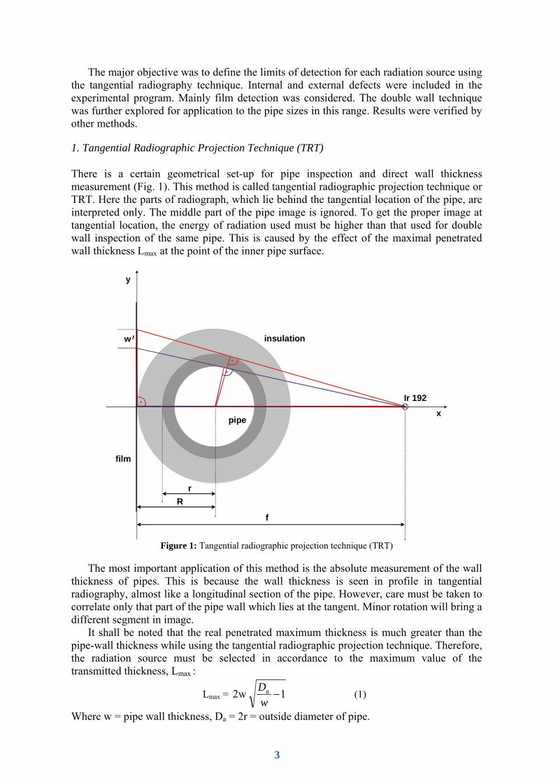
1. Tangential Radiographic Projection Technique (TRT)
There is a certain geometrical set-up for pipe inspection and direct wall thickness measurement (Fig. 1). This method is called tangential radiographic projection technique or TRT. Here the parts of radiograph, which lie behind the tangential location of the pipe, are interpreted only. The middle part of the pipe image is ignored. To get the proper image at tangential location, the energy of radiation used must be higher than that used for double wall inspection of the same pipe. This is caused by the effect of the maximal penetrated wall thickness Lmax at the point of the inner pipe surface.
Ir 192
pipe
film
insulation
Rr
w
f
y
x
Figure 1: Tangential radiographic projection technique (TRT)
The most important application of this method is the absolute measurement of the wall
thickness of pipes. This is because the wall thickness is seen in profile in tangential radiography, almost like a longitudinal section of the pipe. However, care must be taken to correlate only that part of the pipe wall which lies at the tangent. Minor rotation will bring a different segment in image.
It shall be noted that the real penetrated maximum thickness is much greater than the pipe-wall thickness while using the tangential radiographic projection technique. Therefore, the radiation source must be selected in accordance to the maximum value of the transmitted thickness, Lmax :
Lmax = 1 2w −wDa (1)
Where w = pipe wall thickness, Da = 2r = outside diameter of pipe.
3

Selection of higher radiation energy helps in reducing the contrast. Higher contrast would extend the low density zone representative for the inner wall surface projection. That makes the determination of wall thickness difficult. Lower contrast radiographs obtained at higher radiation energy delineate better the ID (inner diameter) profile.
The technique of tangential projection radiography can be used for assessing the residual wall thickness in those segments of pipelines where corrosion or erosion is likely to occur. It can similarly be used for assessing the scaling of ID or finding deposit inside the tubes. This CRP addressed the problem of determining the effectiveness of application for corrosion depth determination in the pipelines and detection of deposit.
2. Correction of Magnification
According to the geometrical set-up of the tangential exposure technique (see fig. 1) there is a magnification factor inherent to this set-up. To consider this, a correction on the evaluated wall thickness must be done. The following correction can be applied. The true wall thickness is:
w = f
R)(fw' −⋅ (2)
Where: w’ is the apparent wall thickness on the radiograph, R is the pipe radius (including insulation) f is the Source Film Distance (SFD).
3. Limits of Tangential Radiographic Projection Technique (TRT)
One of the main aims of the CRP was to establish the application limits of the tangential inspection technique. As a starting point BAM provided a diagram (see fig. 2). It is based on maximum penetrable wall thicknesses of pipes (Lmax) in depending on the radiation energy. Lmax determines the maximum wall thickness which can be inspected at a given pipe outside diameter Da.
If a given combination of outer pipe diameter and wall thickness is exceeding the limiting dashed line for the chosen energy (see fig. 2), this energy can not be applied for successful tangential inspection, because the position of the inner wall cannot be determined from the radiograph. As alternative a higher radiation energy can be used (e.g. replace Ir-192 by Co-60), or the double wall inspection technique (DWT) in the pipe centre for relative wall thickness measurement must be used. According to [6] a wall thickness change can be calculated from the density difference at the film.
4
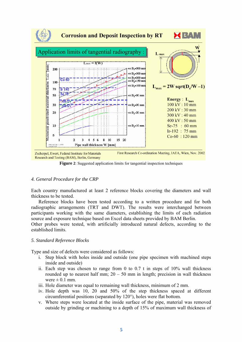
Figure 2: Suggested application limits for tangential inspection techniques
4. General Procedure for the CRP
Each country manufactured at least 2 reference blocks covering the diameters and wall thickness to be tested.
Reference blocks have been tested according to a written procedure and for both radiographic arrangements (TRT and DWT). The results were interchanged between participants working with the same diameters, establishing the limits of each radiation source and exposure technique based on Excel data sheets provided by BAM Berlin. Other probes were tested, with artificially introduced natural defects, according to the established limits.
5. Standard Reference Blocks
Type and size of defects were considered as follows: i. Step block with holes inside and outside (one pipe specimen with machined steps
inside and outside) ii. Each step was chosen to range from 0 to 0.7 t in steps of 10% wall thickness
rounded up to nearest half mm; 20 – 50 mm in length; precision in wall thickness were ± 0.1 mm.
iii. Hole diameter was equal to remaining wall thickness, minimum of 2 mm. iv. Hole depth was 10, 20 and 50% of the step thickness spaced at different
circumferential positions (separated by 120°), holes were flat bottom. v. Where steps were located at the inside surface of the pipe, material was removed
outside by grinding or machining to a depth of 15% of maximum wall thickness of
5
the pipe, forming a flat surface. Length covering all the steps. 30° separation from closest holes. Precision about ± 1%.
vi. Where steps were located at the outside surface of the pipe, material was removed inside by drilling with a 20 – 25 mm diameter tool, parallel to the pipes axis to a depth of 15% of maximum wall thickness of the pipe. 30° separation from closest holes. Length covering all the steps. Precision about ± 1%.
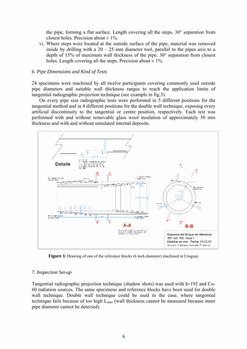
6. Pipe Dimensions and Kind of Tests
24 specimens were machined by all twelve participants covering commonly used outside pipe diameters and suitable wall thickness ranges to reach the application limits of tangential radiographic projection technique (see example in fig.3).
On every pipe size radiographic tests were performed in 5 different positions for the tangential method and in 4 different positions for the double wall technique, exposing every artificial discontinuity to the tangential or centre position, respectively. Each test was performed with and without removable glass wool insulation of approximately 50 mm thickness and with and without simulated internal deposits.
Figure 3: Drawing of one of the reference blocks (6 inch diameter) machined in Uruguay
7. Inspection Set-up
Tangential radiographic projection technique (shadow shots) was used with Ir-192 and Co-60 radiation sources. The same specimens and reference blocks have been used for double wall technique. Double wall technique could be used in the case, where tangential technique fails because of too high Lmax (wall thickness cannot be measured because inner pipe diameter cannot be detected).
6

Figure 4: The finalized test specimen at BAM (8 inch steel pipe with inner and outer wall thickness steps separated for better handling, one 12 inch pipe at exposure arrangement ready for inspection, the other 12 inch pipe with outer wall thickness steps at the floor)
Figure 5: Alignment of the radiation source (Co 60) for the tangential radiographic projection technique. Behind the 12 inch pipe is the film cassette. The pipe sits on a turn table for easy positioning of the different holes in relation to the film.
-2,0
-1,5
-1,0
-0,5
0,0
0,5
1,0
1,5
2,0
1 3 5 7 9 11 13 15 17 19 21 23 25 27true pipe w all thickness [m m ]
mea
n de
viat
ion
[mm
]
film nam e: 12TOH20 results of OH 7-0 at OS 7-0 w ith 20 % w all thickness difference
Figure 6: Example of evaluation results for visual film evaluation of tangential projection technique as
summarized in Excel sheets. The red points show the differences between the mean measured wall thickness and the true wall thickness (mean deviation) at the pipe wall thicknesses inspected, the bars the achieved
accuracy (derived from 2 independent evaluations of 3 different inspectors).
Radiation sources were X-ray (including 2 mm Cu pre-filtering), in most cases Ir-192 or Co-60. Limit energy for x-ray inspection was used 20 % higher than recommended in ISO 5579.
Many details about the radiographic procedure have been established to allow better comparison of experimental results, regarding radiographic arrangement, radiation sources, SFD, Ug, desired density range, exposure time calculation, screen/film systems, magnification correction, shielding against scattered radiation, IQI, film processing and film evaluation procedure.
7

An example of an inspection result in tangential radiographic projection technique (12 inch pipe with 8 to 25 mm wall thickness and 20% outside wholes, exposed with Co-60) is shown in fig. 6. This is one resulting diagram of the developed Excel data sheets exchanged for data collection between all of the participants. The deviation of the measured wall thickness on the film is compared with the true wall thickness determined mechanically after reference block production. The limiting wall thickness in this case is 20 mm, the achieved accuracy about 0.5 mm using the standard procedure for film evaluation in the CRP, without digitalization of films.
In addition, BAM digitized films and developed together with German industry software for computer based inspection of TRT and DWT /7/ (see fig. 7). The developed computer algorithms /3-7/ ensure a higher accuracy compared with visual film evaluation on light boxes.
Figure 7: Example of evaluation results of computer based film evaluation of tangential projection
technique. The digitized film is shown, the positions of the measured profiles, the active profile and the neighboured ones, the geometrical set-up and a table with the results of the wall thickness measurements.
8. Double Wall Technique (DWT) for Pipe Inspection
This technique is suitable for larger size pipes or lower X ray radiation energies, where tangential projection technique is not applicable. The source is kept perpendicular with respect to the pipe axis. Usually two exposures are taken by rotation around the pipe of 90° (figure 8).
8
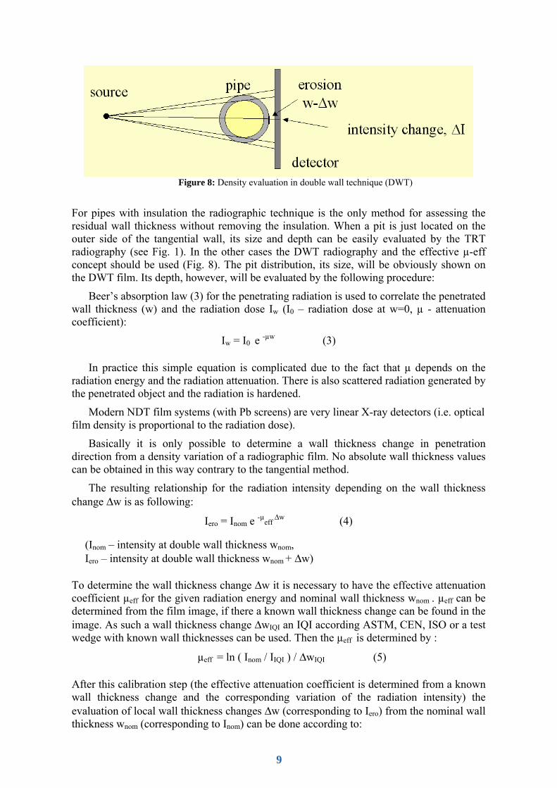
Figure 8: Density evaluation in double wall technique (DWT)
For pipes with insulation the radiographic technique is the only method for assessing the residual wall thickness without removing the insulation. When a pit is just located on the outer side of the tangential wall, its size and depth can be easily evaluated by the TRT radiography (see Fig. 1). In the other cases the DWT radiography and the effective µ-eff concept should be used (Fig. 8). The pit distribution, its size, will be obviously shown on the DWT film. Its depth, however, will be evaluated by the following procedure:
Beer’s absorption law (3) for the penetrating radiation is used to correlate the penetrated wall thickness (w) and the radiation dose Iw (I0 – radiation dose at w=0, µ - attenuation coefficient):
Iw = I0 e -µw (3)
In practice this simple equation is complicated due to the fact that µ depends on the radiation energy and the radiation attenuation. There is also scattered radiation generated by the penetrated object and the radiation is hardened.
Modern NDT film systems (with Pb screens) are very linear X-ray detectors (i.e. optical film density is proportional to the radiation dose).
Basically it is only possible to determine a wall thickness change in penetration direction from a density variation of a radiographic film. No absolute wall thickness values can be obtained in this way contrary to the tangential method.
The resulting relationship for the radiation intensity depending on the wall thickness change Δw is as following:
Iero = Inom e -µeff Δw (4)
(Inom – intensity at double wall thickness wnom, Iero – intensity at double wall thickness wnom + Δw)
To determine the wall thickness change Δw it is necessary to have the effective attenuation coefficient µeff for the given radiation energy and nominal wall thickness wnom . µeff can be determined from the film image, if there a known wall thickness change can be found in the image. As such a wall thickness change ΔwIQI an IQI according ASTM, CEN, ISO or a test wedge with known wall thicknesses can be used. Then the µeff is determined by :
µeff = ln ( Inom / IIQI ) / ΔwIQI (5)
After this calibration step (the effective attenuation coefficient is determined from a known wall thickness change and the corresponding variation of the radiation intensity) the evaluation of local wall thickness changes Δw (corresponding to Iero) from the nominal wall thickness wnom (corresponding to Inom) can be done according to:
9
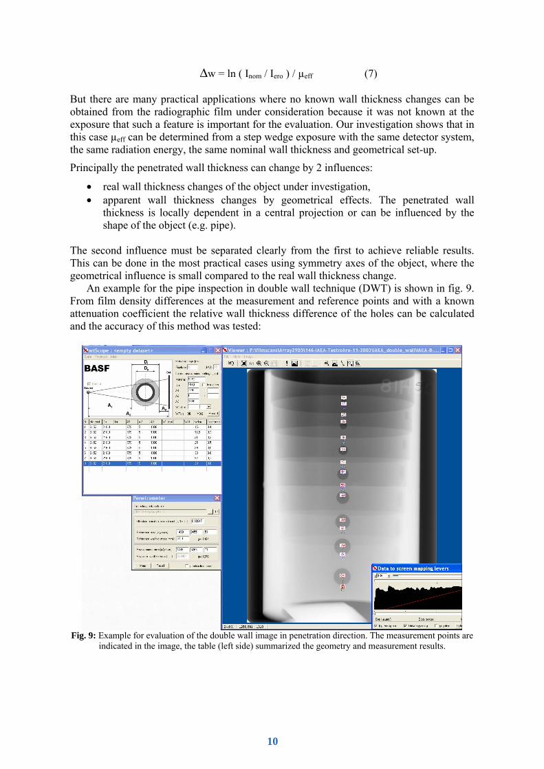
Δw = ln ( Inom / Iero ) / µeff (7) But there are many practical applications where no known wall thickness changes can be obtained from the radiographic film under consideration because it was not known at the exposure that such a feature is important for the evaluation. Our investigation shows that in this case µeff can be determined from a step wedge exposure with the same detector system, the same radiation energy, the same nominal wall thickness and geometrical set-up.
Principally the penetrated wall thickness can change by 2 influences:
• real wall thickness changes of the object under investigation, • apparent wall thickness changes by geometrical effects. The penetrated wall
thickness is locally dependent in a central projection or can be influenced by the shape of the object (e.g. pipe).
The second influence must be separated clearly from the first to achieve reliable results. This can be done in the most practical cases using symmetry axes of the object, where the geometrical influence is small compared to the real wall thickness change.
An example for the pipe inspection in double wall technique (DWT) is shown in fig. 9. From film density differences at the measurement and reference points and with a known attenuation coefficient the relative wall thickness difference of the holes can be calculated and the accuracy of this method was tested:
Fig. 9: Example for evaluation of the double wall image in penetration direction. The measurement points are
indicated in the image, the table (left side) summarized the geometry and measurement results.
10

8.1. Results for Double Wall Technique (DWT) with Ir-192
A large amount of data from the CRP participants was available with Ir-192 and DWT. Fig. 10 shows as example the comparison of results for the test pipes from Uruguay and Iran. Besides the inter-laboratory scattering almost no trend is visible for the dependence of µeff on the penetrated wall thickness. The best estimate from the data is:
µeff = (0.046 +/- 0.005) 1/mm, (8) i.e. the expected mean error is about 10%.
This finding has a strong impact on the practical application of DWT with Ir-192: no calibration is necessary for the investigated range of 4 to 60 mm penetrated steel wall thickness! The expected measurement error is about ±10%.
The histogram of the calculated µeff values for Ir-192 shows a small side concentration around 0.06 1/mm, which is caused by small step holes at the outer pipe side very near to the film. This deviation may be caused by the strong decrease of scattered radiation from the object resulting from these holes.
Double wall technique, Ir 192
0,00
0,01
0,02
0,03
0,04
0,05
0,06
0,07
0,08
0,09
0,10
0 10 20 30 40 50 60
Penetrated steel wall thickness (mm)
Cal
cula
ted
atte
nuat
ion
coef
ficie
nt (1
/mm
)
Uruguay Iran
Uruguay with Insulation Iran with Insulation
Figure 10: Measurement results of the effective attenuation coefficient µeff for Ir-192 and steel pipes from 6” to 10” diameter. The average µeff value is independent from the steel wall thickness and the insulation and is
(0,046 +/- 0,005) 1/mm
8.2. Results for Double Wall Technique (DWT) with Co-60
The observations for Co-60 are very similar to those from Ir-192. The average µeff value was determined to:
µeff = (0.028+/- 0.004) 1/mm, (9) The histogram of the calculated µeff values from the German stepped pipes with 8” and 12” outer diameter shows a strong maximum at the central peak at 0.028 1/mm.
11

Also for Co-60 a special calibration feature is not necessary if an accuracy of ±10% is sufficient. There was no influence by insulation detected. A small side maximum around 0.05 1/mm is caused by the same effect as for Ir-192: deviations for outer holes very near to film.
Conclusions for Selection of Technology
The TRT is suitable for measurement of the wall thickness of pipes. The method was tested for steel pipes with a diameter of 6” – 20” and a wall thickness range of 2 – 30 mm. The accuracy of the wall thickness measurement was determined by an inter-laboratory comparison of TRT of all participants and was found to be ± 0.5 mm for the lower range of wall thickness up to ±1 mm for larger diameter and wall thicknesses.
X-ray sources (≤ 300 keV) are not recommended for the TRT of pipes larger than 6” in diameter. Ir-192 and Co-60 are the recommended sources. Se-75 was not included in the tests and may also be useful for the smaller diameters and/or wall thicknesses.
DWT is suitable for measurement of local wall thickness changes as depth of local corrosion from density differences, whereas TRT is the suitable technique for absolute wall thickness measurements. X-ray and gamma sources can be applied for DWT. The advantage of application of Ir-192 and Co-60 is, that its observed µeff is practically constant (within ± 10%) over the penetrated wall thickness range. The µeff has a low dependence on the insulation thickness and material which is less than 10%. A calibration procedure is not required if an accuracy of ± 10% is sufficient. For measurements of depth of local corrosion (e.g. pitting) within an accuracy of ± 0.5 mm, but not better than 10% of the wall thickness, the following equations are applicable for steel pipes: Ir-192: Δw[mm] = ln((Dpit-D0)/(Dbackground-D0 ))/0.046 (density range 1.5 to 4) Co-60: Δw[mm] = ln((Dpit-D0)/(Dbackground-D0 ))/0.028 (density range 1.5 to 4) The application of X-ray sources has the potential of obtaining a higher accuracy, but it requires the calibration of the system for determination of correct µeff values, which depends on the wall thickness, insulation thickness and material. It is also emphasised, that µeff depends on the spectrum of the X-ray source, which is determined by the target material, target angle, the radiation window material and thickness as well as the power supply and its calibration and fluctuations. Pre-filters in front of the tube port shall be used always.
The TRT is not suitable for searching of internal local area corrosion (e.g. pitting). Inner flat bottom holes of up to 20% depth of wall thickness (situated 90° to the radiation beam) and the inner ground patch were not seen in a wide range of diameters and wall thicknesses. Even the inner 50% holes were not reliably detected in the thicker and thinner wall thickness range. Outer local area corrosion was better detected, than inside corrosion, if the exposure has no burn off outside the pipe. For better detection of inside corrosion and deposits a second exposure is recommended with an optical density > 1.5 in the region of the inner wall projection (at Lmax).
TRT is suitable for detection of large area corrosion, erosion and deposit detection by change of the measured wall thickness. Since there is a very low probability of detection of local area corrosion, a DWT evaluation is needed if local area corrosion shall be found.
Three exposure techniques are proposed for TRT with different specifications for optical density (D):
• Dcentral = 2 technique for TRT and DWT with the same film • D=4 (outside pipe) technique for TRT to measure the wall thickness at one film
12

• D=8 (outside pipe) technique for TRT to measure the wall thickness at two films of different speed or by removing the emulsion at one side of the film to reduce the density to D < 4 in the burn off area at the outer pipe edge projection.
The BAM diagram (see fig. 2) with Lmax = f(w, diameter) was applied for determination of the application limits of the three methods for Ir-192 and Co-60. This diagram indicates also the upper limit of wall thickness and diameters of pipes for the practical application using TRT depending on the source. The maximum limits of Lmax for Ir-192 and Co-60 were found lower than expected from the former CRP (small diameter pipes) but larger than proposed by BAM. Those limits for Lmax depend on the radiation source and the film system. T3 film systems (see ISO 11699-1: here: Agfa D7, developed corr. to manufacturer’s requirements) were used in this CRP:
Table 1: Determined Lmax limits and µeff-values for TRT for Ir-192 and Co-60 and T3 film systems Ir-192 Co-60 µeff 0.046 mm-1 0.028 mm-1 Dmax = 4 80 mm 130 mm Dmax = 8 95 mm 155 mm
Industrial benefit
Radiography is the only NDT-method which does not require un-insulating of pipes in chemical and energy industries for evaluation of corrosion and measurement of pipe wall thickness. The estimated market for exposed films for corrosion inspection alone amounts to nearly 100 million US$ per year. This marked is expected to grow, because more and more large chemical and energy enterprises are realising the advantage of this technology. It requires urgently the release of guidelines and standards to avoid incorrect application of this method and avoidance of risk of overseen indications, especially in the inner wall area. The industrial benefits of the results of this CRP are the development of a testing procedure for the tangential and double wall technique. Operators can easily select the correct exposure conditions, radiation source and exposure geometry.
Less expensive NDT-techniques need the removal of insulation for contact measurements (e.g. UT). Long time observations have proven that this leads to outer corrosion of pipes which are situated out side of protecting buildings. Furthermore, the periodical radiological testing enables companies to predict the life time of their pipes and to save unreasonable maintenance costs by shorter inspection and exchange periods. Longer working periods and fewer service periods result in significant cost reductions.
The findings of the project contribute to a saver analysis of the exposed radiographs. The risk of overseen inner local corrosion in TRT could be clearly proven. A detailed practice was developed with unique requirements for the number of exposures and exposure condition. This will reduce the risk of overseen indications.
Environmental benefits
Broken or corroded pipes, carrying dangerous agents as chemicals or gas and oil, may cause serious damages of the environment and endanger technological equipment as well as the life of people. Only the periodical inspection for the integrity of pipes and equipment can reduce the risk in connection with other maintenance activities.
The results of the CRP allow the prediction of failure of pipes caused by corrosion and erosion as well as the reduction of the free inner cross section by unwanted deposit. This is considerable contribution to the safety of industrial plants and human life.
13

The new procedure reduces also the required number of films for inspection due to the guidance in the recommended practice, which allows the usage of one film for TRT and DWT in a special range of wall thicknesses and diameters.
References
[1] Burkle, W.S., “Application of the tangential radiographic technique for evaluating pipe system erosion/corrosion.”, Materials Evaluation, Vol. 47 (1989), 1184.
[2] Lee, S., Kim. Y.H., “Determination of pipe thickness using tangential radiography and film density-thickness correlation.”, IAEA Report 1999
[3] Onel, Y., Ewert, U., Willems P., “Radiographic Wall Thickness Measurements of Pipes by a New Tomographic Algorithm”, IDN 369, Proceedings of the 15th WCNDT, Roma 2000.
[4] Wawrzinek, T., Zscherpel, U., Bellon, C., “Wall Thickness Determination in Digital Radiography”, COFREND Congress on NDT, Nantes 1997, conference proceedings, vol. 1, pp. 79 -83
[5] Willems, P., Vaessen, B., Hueck, W., Ewert, U., “Applicability of computer radiography for corrosion and wall thickness measurements”, INSIGHT, vol. 41 (1999) No. 10, pp. 635 - 637
[6] Zscherpel, U., Bellon, C., Nimtz, R., “Wall Thickness Estimation from Digitized Radiographs”, proceedings of the 7th ECNDT, Copenhagen 1998, pp. 2819 – 2825
[7] Zscherpel, U., Alekseychuk, O., Bellon, C., Ewert U., BAM Berlin, Rost P., Schmid, M., BASF AG Ludwigshafen, „Korrosionsmapping an Rohrleitungen“, proceedings of DGZfP Jahrestagung 2002, Weimar, Berichtsband 80-CD
14