radiologic - static.crowdwisdomhq.comstatic.crowdwisdomhq.com › asrt › documents ›...
TRANSCRIPT

Journal of the American Society of Radiologic Technologists Vol. 83, No. 5 May/June 2012
RADIOLOGIC®
American Society ofRadiologic Technologists
Persistent Pain Following Lumbar Disc Replacement
Influence of Gender, Age, and Social Norm on Digital Imaging Use
Radiation Safety for Radiologic Technologists
Imaging Rheumatic Diseases


• Arenson, Ronald L. and Cathy Garzio—A PRACTICALGUIDE TO LEADERSHIP AND MANAGEMENT INACADEMIC RADIOLOGY. '11, 274 pp. (7 x 10), 25 il., 2tables.
• Perotto, Aldo O.—ANATOMICAL GUIDE FOR THEELECTROMYOGRAPHER: The Limbs and Trunk.(5th Ed.) '11, 396 pp. (7 x 10), 240 il., $69.95, hard, $49.95,paper.
• Carroll, Quinn B.—RADIOGRAPHY IN THE DIGITALAGE: Physics - Exposure - Radiation Biology. '11, 866 pp.(7 x 10), 641 il., 62 tables, $89.95, hard.
• Carroll, QuinnB.—STUDENT WORKBOOK FORRADIOGRAPHY IN THE DIGITAL AGE. '11, 246 pp. (81/2 x 11), (spiral) paper, $39.95.
• Carroll, Quinn B.—INSTRUCTOR RESOURCES FORRADIOGRAPHY IN THE DIGITAL AGE. '11,CD-ROM, $299.95.
• POWERPOINT SLIDE SERIES The Physics and Equipment of Radiography DVD, $299.95The Principles of Radiographic Imaging DVD, $299.95The Digital Image Acquisition and Display DVD, $299.95The Radiation Biology and Protection DVD, $299.95
• Carroll, Quinn B.—PRACTICAL RADIOGRAPHICIMAGING. (8th Ed.) '07, 666 pp. (7 x 10), 352 i1., 40tables, $64.95, cloth.
• Carroll, Quinn B.—Instructor’s Manual for Use WithPRACTICAL RADIOGRAPHIC IMAGING (8th Ed.)'07, 224 pp. (7 x 10), $22.95, spiral (paper).
• Mann, Robert W., & David R. Hunt—PHOTOGRAPHICREGIONAL ATLAS OF BONE DISEASE: A Guide toPathological and Normal Variation in the Human Skel-eton. (2nd Ed.) '05, 318 pp. (8 1/2 x 11), 234 il., 4 tables,$69.95, hard, $49.95, paper.
Book Savings*
(on separate titles only)Save 10% on 1 Book !Save 15% on 2 Books !Save 20% on 3 Books !
P.O. Box 19265, Springfield, IL 62794-9265Call 1-800-258-8980 or 1-217-789-8980
or Fax 1-217-789-9130Complete catalog available at www.ccthomas.com
[email protected] sent on approval • Shipping charges: $9.75 U.S. / Outside U.S., actual
shipping fees will be charged • Prices subject to change without notice
*Savings include all titles shown here and on our web site. For a limited time only.
When ordering, please refer to promotional codeRADT0512 to receive your discount.
In the race for a great career, Cross Training gives you a head start!MTMI has the training you have been looking for ...
Mammography: April 25-29 in Dallas, TX June 20-24 in San Jose, CA July 9-13 in Boston, MA July 17-21 in Milwaukee, WI Aug 15-19 in Las Vegas, NV Sept 5-9 in Atlanta, GA Sept 18-22 in Milwaukee, WI Oct 10-14 in Seattle, WA Oct 24-28 in Atlantic City, NJ Nov 6-10 in Milwaukee, WI Bone Densitometry: April 21-22 in Hartford, CT May 5-6 in Denver, CO June 23-24 in Kansas City, MO Oct 19-21 in Milwaukee, WI
Healthcare LeadershipTraining: Oct 5-7 in Milwaukee, WI
Breast Ultrasound: April 14-15 in Minneapolis, MN May 4-6 in Milwaukee, WI June 9-10 in Charlotte, NC July 27-29 in Milwaukee, WI Aug 11-12 in Washington, DC Oct 13-14 in Denver, CO Oct 18-19 in Boston, MA Nov 2-4 in Milwaukee, WI Dec 1-2 in Sacramento, CA
Computed Tomography: June 4-8 in Milwaukee, WI Sept 10-14 in Milwaukee, WI Nov 12-16 in Milwaukee, WI
Stereotactic Breast Biopsy: June 22-23 in Milwaukee, WI Sept 14-15 in Milwaukee, WI
Magnetic Resonance Imaging: Apr 30 - May 11 in Milwaukee, WI Aug 6-17 in Milwaukee, WI Oct 22 - Nov 2 in Milwaukee, WI
Medical Dosimetry - An Initial Training Course Part I: Sep 5-8 in Milwaukee, WI Medical Dosimetry - An Initial Training Course Part II: Oct 17-20 in Milwaukee, WI
Get on the right track today!Call 800-765-6864
or go to www.mtmi.net or scan this QR code
423RADIOLOGIC TECHNOLOGY May/June 2012, Vol. 83/No. 5
An Official JournalRadiologic Technology (ISSN 0033-8397) is the
official scholarly/professional journal of the American Society of Radiologic Technologists. It is published bimonthly at 15000 Central Ave SE, Albuquerque, NM 87123-3909. Months of issue are January/February, March/April, May/June, July/August, September/October and November/ December. Periodical class postage paid at Albu-querque, NM, and at additional mailing offices. Printed in the United States. ©2012 American Society of Radiologic Technologists.
The research and information in Radiologic Technology are generally accepted as factual at the time of publication. However, the ASRT and authors disclaim responsibility for any new or contradictory data that may become available after publication. Opinions expressed in the Journal are those of the authors and do not necessarily reflect the views or policies of the ASRT.
PostmasterPostmaster: Send change of address to
Radiologic Technology, c/o the American Society of Radiologic Technologists, 15000 Central Ave SE, Albuquerque, NM 87123-3909.
EditorialRadiologic Technology is a peer-reviewed
journal produced by the American Society of Radiologic Technologists for the benefit and advancement of all technological disciplines within medical imaging and radiation therapy. Editorial correspondence should be addressed to Radiologic Technology Editor at communications @asrt.org, 505-298-4500, or 15000 Central Ave SE, Albuquerque, NM 87123-3909. Letters of inquiry prior to finished manuscript production are encouraged and frequently may be reviewed by both the editor and the chairman of the Edi-torial Review Board.
The initials “R.T.” following proper names in this journal refer to individuals certified by the American Registry of Radiologic Technologists.
Subscriptions, Change of AddressASRT member change of address: Address
correspondence to the American Society of Radiologic Technologists, Attention: Member Services, 15000 Central Ave SE, Albuquerque, NM 87123-3909. Call the ASRT office from 8 a.m. to 4:30 p.m. Mountain time at 800-444-2778; fax 505-298-5063. ASRT members also can submit changes of address online at www.asrt.org/myinfo.
Nonmember subscriber change of address: Send an old mailing label and the new address, including ZIP code, at least 6 weeks in advance to ASRT, Attention: Member Services, 15000 Central Ave SE, Albuquerque, NM 87123-3909. Claims are not allowed for issues lost as a result of insufficient notice of change of address. The publisher cannot accept responsibility for unde-livered copies.
Subscription rates and order processing: Member subscription is $7.82 per year, included in ASRT member dues. Nonmember subscription of one volume of 6 issues is $70 within the United States for individuals; foreign, $105, including Canada. Institutional rates also are available. Discounted rates apply to 2- and 3-year subscrip-tions and subscription agencies. Single issues, both current and back, exist in limited quantities and are offered for sale. For prices and availability, visit www.asrt.org/store or phone ASRT Member Services at 800-444-2778. Journal orders must be paid in advance by check, money order, or credit card drawn on a U.S. bank in U.S. funds only. Send payment to ASRT, PO Box 27447, Albuquerque, NM 87125-7447. Prices are subject to change.
AdvertisingAll commercial display advertising and classified
advertising is handled by the ASRT Corporate Rela-tions Department, 15000 Central Ave SE, Albuquer-que, NM 87123-3909. For information on rates and deadlines, contact Robin Treaster at 800-444-2778, Ext. 1317, or e-mail [email protected].
Radiologic Technology reserves the right to reject or revise any advertising copy that it considers objectionable, either because said copy is not consistent with usual professional standards of propriety or for any other reason deemed material. In any event, the advertiser assumes full liability for the content of all advertising copy printed.
All advertising materials submitted become the property of ASRT. Advertisements submitted beyond the deadline for proof service are done so at the advertiser’s risk. Publication of an advertise-ment in Radiologic Technology does not imply en-dorsement of its claims by the editor or publisher. For advertising specifically related to educational programs, ASRT does not guarantee, warrant, claim or in any way express an opinion relative to the accreditation status of said program.
Rights ReservedAll articles, illustrations and other materials
carried herein are pending copyright under U.S. copyright laws, and all rights thereto are reserved by the publisher, the American Society of Radiologic Technologists. Any and all copying or reproduction of the contents herein for general distribution, for advertising or promotion, for creating new collective works or for resale is expressly forbidden without prior written approval by the publisher and, in some cases, the authors.
Copying for personal use only through application and payment of a per-copy fee as re-quired by the Copyright Clearance Center, under permission of Sections 107 and 108 of the U.S. copyright laws. Violators will be prosecuted.
Member ofBPA International

Saint Joseph’s College of Maine offers online undergraduate and graduate programs in the field of health care: •RadiologicScienceAdministration •HealthCareAdministration •MasterofHealthAdministration
RadiologicTechnologyProgramcreditsareacceptedtowards a degree for radiologic technologists.
Flexible online format makes it convenient to earn yourdegreefromanywhereatanaffordablecost.
Earn an associate’s, bachelor’s or master’s degree online. Advanceyourprofessionalcareer!
Visit: online.sjcme.edu/rs Call: 800-752-4723 Find us on Facebook!
Saint Joseph’s College of Maine
100 YEARS 1912-2012
Saint Joseph’s College Online
WH
ERE CAN TECH
NOLOGY TAKE YOU
?
Bachelor of Science Degree in
RADIOLOGICAL SCIENCE
An upper-division program created for graduates of an associate degree or certifi cate level program accredited by the JRCERT, and registered by the ARRT or equivalent. Graduates of a JRCERT accredited AAS program may be awarded up to 65 transfer credits. Certifi cate level graduates may transfer up to 41 credits.
LEARN THE LASTEST RADIO-LOGICAL TECHNOLOGY AND ADVANCE YOUR CAREERSInterested in professional develop-ment and career advancement? Graduates will enhance their knowledge and skills in all modali-ties of imaging, with an emphasis on emerging technologies. They will also gain the background necessary to advance into leadership positions.
300 Jay Street • Brooklyn • NY11201 718.260.5360 | www.citytech.cuny.edu/bsrsAPPLY FOR FALL 2012 SEMESTER NOW
State-of-the-artlaboratories
Classes evenings and weekends
Partially on-line to fi t busy schedules
Affordable CUNY tuition

ASRTEducation and
Research Foundation
®
Imagine with us | Believe with us | Achieve with us
www.asr t foundat ion .org | 800-444-2778
©2012 ASRT Education and Research Foundation. All rights reserved.
ASRT FoundationWin great prizes. Help R.T.s Succeed. Win great prizes. Help R.T.s Succeed. Help R.T.s Succeed.
Annual Drawing
Proceeds from the Annual Drawing go toward ASRT Foundation programs that support and empower radiologic science professionals and students.
Minimum contribution for ticket is not necessary to enter or win. ASRT members may obtain information about receiving one complimentary chance to win by dialing 800-444-2778. Complimentary tickets can be processed only by mail and can be transacted only between Monday, May 14, 2012, at 8 a.m. Mountain time through Sunday, August 12, 2012, at 11:59 p.m. Mountain time.
*Odds based on the number of ticket holders from the previous drawing. Only ASRT members are eligible to purchase tickets. You must be an ASRT member to claim your prize.
Tickets are only $20. Discounted multi-ticket packages
are also available.
You Win Either Way.
Buy tickets now!
Odds of winning a prize:
1 in 955*
www.asrtfoundation.org/YouWin or call 800-444-2778
Grand PrizeYour choice of a resort vacation to Hawaii;Palm Springs, Calif.; or Key Largo, Fla.
Second PrizeXPS 13 Ultrabook laptop computer with case, mouse and printerDonated by Dell, an ASRT Member Perks partner offering a30% discount on select systems Dell.com/asrt
Third Prize$500 shopping spree for the entire family at Kohl’s
ERF12_AD_fp.indd 1 4/25/12 10:20 AM

426 May/June 2012, Vol. 83/No. 5 RADIOLOGIC TECHNOLOGY
RadiologicTechnologyEditorialReview Board
ASRT Journal Staff Lisa Kisner, scientific journal editorKim Agricola, scientific journal editorJenna Frosch, associate editorCharles Poling, director of communicationsEllen Lipman, director of professional development
Julie James-Griego, art director Marge Montreuil, graphic designerLaura Reed, graphic designerLoren Stacks, graphic designer
ASRT Office 15000 Central Ave SE Albuquerque, NM 87123-3909Phone: 800-444-2778; Fax: 505-298-5063
For questions regarding subscriptions or missing issues, phone Member Services at 800-444-2778 or e-mail [email protected].
For advertising information, contact Robin Treaster, advertising and sponsorship coordinator, at Ext. 1317 or [email protected].
For questions about submitting an article, e-mail [email protected].
ChairmanNina K Kowalczyk, PhD, R.T.(R)(CT)(QM), FASRTThe Ohio State University Columbus, Ohio Vice ChairmanJames Johnston, PhD, R.T.(R)(CV)Midwestern State UniversityWichita Falls, Texas MembersLaura Aaron, PhD, R.T.(R)(M)(QM)Northwestern State UniversityShreveport, Louisiana
Melissa B Jackowski, EdD, R.T.(R)(M)University of North CarolinaChapel Hill, North Carolina
Jeffrey S Legg, PhD, R.T.(R)(CT)(QM)Virginia Commonwealth UniversityRichmond, Virginia
Tricia Leggett, DHEd, R.T.(R)(QM)Zane State CollegeZanesville, Ohio
Rebecca Ludwig, PhD, R.T.(R)(QM), FAEIRS, FASRT University of Arkansas for Medical Sciences Little Rock, Arkansas
Michael E Madden, PhD, R.T.(R)(CT)(MR)Fort Hays State UniversityHays, Kansas
Kimberly Metcalf, EdD, R.T.(R)(T)(MR)Massachusetts General HospitalInstitute of Health ProfessionsBoston, Massachusetts
Dwayne Richardson, MSN, R.T.(R), RNHahnemann University HospitalPhiladelphia, Pennsylvania
Joan E Siederer, MPH, R.T.(R)Princeton, New Jersey
Christina A Truluck, PhD, R.T.(N), CNMTThomas Jefferson UniversityPhiladelphia, Pennsylvania
Bettye G Wilson, MEd, R.T.(R)(CT), RDMS, FASRTUniversity of Alabama at BirminghamBirmingham, Alabama
Ben D Wood, MSRS, R.T.(R)Northwestern State UniversityShreveport, Louisiana
©2009 ASRT. All rights reserved.
l Search and apply for jobs online.
l Job Alerts e-mailed to you when job postings match your preferences.
l ASRT Salary Estimator provides a salary comparison to other R.T.s in your state who work in the same specialty as you do.
l Résumé Builder allows you to upload an existing résumé or create a new one.
www.asrt.org/jobs
ASRT’s JobBank® is the source for job seekers in the radiologic sciences.
An R.T.’s Best Friend!

428 May/June 2012, Vol. 83/No. 5 RADIOLOGIC TECHNOLOGY
PEER-REVIEWED ARTICLES
COLUMNS & DEPARTMENTS
DIRECTED READING ARTICLES
Persistent Pain Following Lumbar Disc ReplacementKevin L Wininger, Kedar K Deshpande, Michelle L Bester . . . . . . . . . . . . . . . .430
Influence of Gender, Age, and Social Norm on Digital Imaging UseNina Kowalczyk . . . . . . . . . . . . . . . . . . . . . . . . . . . . . . . . . . . . . . . . . . . . . .437
Radiation Safety for Radiologic TechnologistsLee A Bradley . . . . . . . . . . . . . . . . . . . . . . . . . . . . . . . . . . . . . . . . . . . . . . .447
Imaging Rheumatic DiseasesApril Reynolds . . . . . . . . . . . . . . . . . . . . . . . . . . . . . . . . . . . . . . . . . . . . . . .467
Editor’s Note . . . . . . . . . . . . . . . . . . . . . . . . . . . . . . . . . . . . . . . . . . . . . . 429My Perspective . . . . . . . . . . . . . . . . . . . . . . . . . . . . . . . . . . . . . . . . . . . 497Technical Query . . . . . . . . . . . . . . . . . . . . . . . . . . . . . . . . . . . . . . . . . . 499RE: Registry . . . . . . . . . . . . . . . . . . . . . . . . . . . . . . . . . . . . . . . . . . . . . . 500Teaching Techniques . . . . . . . . . . . . . . . . . . . . . . . . . . . . . . . . . . . . . 503Writing & Research . . . . . . . . . . . . . . . . . . . . . . . . . . . . . . . . . . . . . . . 507Case Study . . . . . . . . . . . . . . . . . . . . . . . . . . . . . . . . . . . . . . . . . . . . . . . . 510Management Toolbox . . . . . . . . . . . . . . . . . . . . . . . . . . . . . . . . . . . . . 515Patient Page . . . . . . . . . . . . . . . . . . . . . . . . . . . . . . . . . . . . . . . . . . . . . . 523
On the Cover: “Shoulder Boulder” demonstrates the cliff-like drop off of the acro-mioclavicular region of the shoulder. In the fifth painting in a radiograph landscape series, Lizzy Rainey, R.T.(R), of Lafayette, Indiana, created this shoulder view that sits boldly in a serene lake sur-rounded by vibrant woods.
CONTENTS. . . . . . . . . . . . . . . . . . . . . . . . . . . . . . . . . . . . . . . . . . . . . . . . . . . . . . . . . . . . . . . . . . . . . . . . . . . . . . . . . . . . . . . . . . . . . . . . . . . . .
Volume 83/Number 5May/June 2012

. . . . . . . . . . . . . . . . . . . . . . . . . . . . . . . . . . . . . . . . . . . . . . . . . . . . . . . . . . . . . . . . . . . . . . . . . . . . . . . . . . . . . . . . . . . . . . . . . . . . . . . . . . .
429RADIOLOGIC TECHNOLOGY May/June 2012, Vol. 83/No. 5
TECHN EDITOR’S NOTE ICAL QUERY
Lisa M Kisner
“Editor’s Note” offers Radiologic Technology readers insight into the Journal.
Three Cheers for Our VolunteersEvery year, hundreds of ASRT volun-
teers work diligently on countless proj-ects. From the Board of Directors and House of Delegates to educational curri-cula and advocacy committees, our dedi-cated members donate their expertise and dollars to keep the Society on track. Each volunteer makes a difference and we appreciate every penny and second of time donated.
One such hard-working group makes this Journal possible. The Radiologic Technology Editorial Review Board (ERB) collectively spends more than 1500 hours each year reviewing manuscripts, provid-ing authors with feedback, writing arti-cles, and presenting at educational con-ferences. Because peer-reviewed research is held to a higher standard than other articles and is at the core of scholarly publications, the primary responsibility of the 14-member committee is scrutiniz-ing submissions to ensure they advance the profession. Each ERB member has a unique but well-established background in radiologic technology that makes him or her the perfect “peer” to review your profession’s latest research.
Whatever level of involvement you may be looking for, the Journal is a great place to volunteer your time.
If you just want to get your feet wet, consider jotting down some notes about a particular trick you use in the clinic. Send your notes or a summary of your idea to [email protected], and we will help you turn them into a col-umn. The practical tips you take for granted might help technologists across the country. Writing a short column is the perfect volunteer opportunity for R.T.s with limited time who want to give back.
Or maybe you are researching a hot topic and looking for the ideal journal to publish your findings. Not only has Radiologic Technology been in print since 1929, but we also have the largest cir-culation of any radiologic technology publication in the world. Submitting
your article through our online system (asrt.msubmit.net) is the natural next step in reaching your ideal audience.
If you have published scholarly articles and are looking for more hands-on involvement, I encourage you to submit a letter of interest and résumé to the ERB chairman, Nina Kowalczyk, PhD, R.T.(R)(CT)(QM), FASRT, at [email protected]. We have 2 open ERB posi-tions to fill this summer, so she would like to hear from you by July 1. If you are selected, expect to spend approximately 80 hours per year of a 3-year term fulfill-ing ERB duties.
Among the numerous radiology magazines printed today, we produce Radiologic Technology specifically for R.T.s like you — and none of it would be pos-sible without volunteers. Please accept my sincere thanks to all our past, present, and future authors and ERB members.
Lisa M Kisner, BA, CQIA, is an ASRT scientific journal editor. She has worked for ASRT for 10 years in a variety of capaci-ties and now enjoys managing Radiologic Technology.
Check out Lisa’s digital recap of this issue online now. Visit www .asrt.org/publications.

peer review
430 May/June 2012, Vol. 83/No. 5 RADIOLOGIC TECHNOLOGY
. . . . . . . . . . . . . . . . . . . . . . . . . . . . . . . . . . . . . . . . . . . . . . . . . . . . . . . . . . . . . . . . . . . . . . . . . . . . . . . . . . . . . . . . . . . . . . . . . . .
Background Pain patterns associated with the facet and sacroiliac joints following lumbar total disc replacement correlate with biomechanical modeling observations, such as load transfer to the posterior spinal elements in total disc replacement with an artificial disc. When conventional treatment options are exhausted, spinal cord stimulation (SCS) offers clinically favorable outcomes to treat intractable pain.Objectives To contribute to the literature on neuroaugmentive techniques and on pain following disc replacement, and to highlight recent advances and forward-thinking concepts for nonsurgical intradiscal therapies.results Three years of injection therapies and physical therapy did not significantly alleviate the patient’s pain. A trial period of SCS rather than reoperation (fusion surgery) was elected. A constant-current multiple source SCS system was implanted. At 12-month follow-up for this system, the patient’s pain had been reduced by more than 75%, and the patient reported improved quality of life, including a return of restful sleep.Conclusions SCS is a viable technique to control pain associated with artificial disc implant.
KEvIN L WININGER, BS, R.T.(R), RKTKEDAR K DESHpANDE, MDMICHELLE L BESTER, MSN, CNp
persistent pain Following Lumbar Disc Replacement
at adjacent levels.3 In comparison, large increases in motion with a corresponding increase in facet loads were noted in classical testing alone (excluding the implant), though they were clinically insignificant.3
Siepe et al offered general remarks on pain patterns following total disc replacement.6 First, lumbar facet/sacroiliac joint pain is a frequent and underestimated source of postoperative pain and the most common reason for unsatisfactory results following disc replace-ment. Next, patients who reported an early onset of pain (6 months or sooner after surgery) had 2 to 59 times higher risk of developing persisting problems and unsatisfactory outcomes. Finally, an inferior outcome and a significantly higher incidence of posterior joint pain were observed for disc replacement at the L5-S1 level and disc replacements at the combined L4-L5/L5-S1 levels, 21.6% and 33.3%, respectively. See Figure 1 for postoperative lumbar facet joint subluxation.
When pain becomes intractable to conventional treatment methods, pain management through spinal cord stimulation (SCS) can offer clinically favorable outcomes.7 SCS systems are implantable devices that
Current anterior abdominal, transperitone-al techniques for lumbar total disc replacement disrupt stabilizing ligaments and the annulus fibrosus of the spinal motion segment (the adjacent vertebrae
along with interconnecting soft tissues).1,2 Moreover, postoperative scarring compromises the restoration of normal kinetics and biomechanics of the spine, and excessive scarring can compromise a surgeon’s ability to safely approach the spine during revision surgery.1
Biomechanical models examining the Charité arti-ficial disc (DePuy Spine Inc, Raynham, Massachusetts) populate the literature.3-5 One early study with a high degree of clinical relevance for the L5-S1 disc implant came from Goel et al,3 in which classical testing of the intact spine (the load-control only model) was integrated with the mechanical construct (a Charité implant). Test results showed slight increases in motion at the inferior endplate of the L5 vertebral body rela-tive to the osseous-device interface — accompanied by an increase in facet loading when compared with the adjacent segments and decreases in motion and loads

. . . . . . . . . . . . . . . . . . . . . . . . . . . . . . . . . . . . . . . . . . . . . . . . . . . . . . . . . . . . . . . . . . . . . . . . . . . . . . . . . . . . . . . . . . . . . . . . . . . . . . . . . . .
431RADIOLOGIC TECHNOLOGY May/June 2012, Vol. 83/No. 5
WININGER, DESHpANDE, BESTER
During initial consultation, the patient stated her pain had begun insidiously 13 months ago and progres-sively worsened. Lumbar hyperextension aggravated her pain more than lumbar flexion, although both motions negatively affected her mobility. The patient complained of sharp jabbing with positional changes, along with local pain in the lumbar spine that included radiating pain in both legs. She further emphasized that the pain was more intense on her right side. Overall, the patient reported a pain score of 6 out of 10 on the visual analog scale. The patient’s medication regimen consisted of oral morphine, oxycodone (for break-through pain control), gabapentin, bupropion, and zolpidem.
A postdiscography computed tomography (CT) scan performed in November 2006 was available for our review. Findings included normal L3-L4 disc morphology; a small central disc bulge or protrusion at L4-L5 with no annular tear (but clear evidence of loss of disc height when compared with the L3-L4 disc); and diffuse mild disc bulging at L5-S1 with no annular tear. We did not consider the patient to be a candidate for IDET based mostly on these imaging findings.10 We recommended a treatment plan that included injection therapy (eg, medial branch blocks) and physical therapy. The patient consented, and listed her goals as follows:
■ Pain reduction.■ Pain medication reduction.■ Improved physical activity.■ Improved sleep patterns.Despite compliance with her plan of care, the fre-
quency and intensity of the patient’s low back and radiculopathy pain gradually became worse (visual analog scale 9 out of 10). This included signs and symptoms of reflex sympathetic dystrophy in her right lower extremity, such as discoloration and temperature changes. We modified the patient’s treatment plan to attempt to isolate the pain generators (see Figure 2). Pain relief from injections was lasting only a few weeks at best, and the patient was unable to continue physi-cal therapy because of her pain. For these reasons, a magnetic resonance (MR) imaging examination was ordered in October 2008 to evaluate her lumbar spine. A broad-based disc bulge was identified on the MR images at the L4-L5 level, which superimposed the pre-viously identified central disc protrusion. Indentation of the ventral thecal sac, which resulted in mild spinal stenosis and foraminal narrowing, also was noted at this level. Electrodiagnostic evidence of the patient’s
electrically stimulate the spinal cord’s dorsal structures to influence the afferent pain pathways. Influencing afferent pathways mediates the pain response. The patient often experiences a paresthesia (which serves as an analgesic) in place of the pain.8,9 We report on the management of persistent pain following a total disc replacement at the L5-S1 level with a Charité artificial disc over a patient’s 4-year history under our care, with pain control ultimately achieved by means of SCS. In addition, we outline bioengineering concepts (as well as a prospective neuromodulation technique) concern-ing disc regenerative medicine and intradiscal and alternative therapies, such as intradiscal electrothermal therapy (IDET).
Case reportA 32-year-old woman was referred to our center and
evaluated in May 2007 to determine appropriateness of IDET for persistent low back pain and lower limb radiculopathy following an L5-S1 total disc replacement with a Charité disc implant performed 3 months earlier. Although the surgeon intended to replace the L4-L5 disc at the same time, anatomic restraints caused by vas-cular problems prevented replacement at that level.
Figure 1. Postoperative subluxation of the lumbar facet joints.

. . . . . . . . . . . . . . . . . . . . . . . . . . . . . . . . . . . . . . . . . . . . . . . . . . . . . . . . . . . . . . . . . . . . . . . . . . . . . . . . . . . . . . . . . . . . . . . . . . . . . . . . . . .pAIN FOLLOWING DISC REpLACEMENT
432 May/June 2012, Vol. 83/No. 5 RADIOLOGIC TECHNOLOGY
disc nonfunctional because it was bound in a flexed position because of this slippage. The surgeon recom-mended posterior salvage rather than anterior revision. As a result, fixation from L4 to the sacrum, interbody arthrodesis at L4-L5, and posterolateral fusion at L4-L5 and L5-S1 was offered. The surgeon also noted that SCS would be a viable treatment option because any decompression fusion with fixation would not address the reflex sympathetic dystrophy-type symptoms. Ultimately, the patient decided against undergoing a surgical correction, opting instead for an SCS trial.
Neuromodulation In May 2010, we implemented a 7-day SCS trial
period using dual parallel percutaneous leads (Linear Lead, Boston Scientific Neuromodulation, Valencia, California)(see Figure 3). At follow-up, the patient reported she had been pain-free throughout this period. Subsequently, in September 2010, in accor-dance with the patient’s goals and informed consent, the leads and corresponding constant-current mul-tiple source SCS system (Precision, Boston Scientific Neuromodulation, Valencia, California) was implanted (see Figure 4). At the 12-month follow-up, no complica-tions (such as loss of coverage because of lead displace-ment, lead fracture, or erosion) or adverse side effects had been reported. Stimulation use is continuous over a 24-hour interval, and the patient attributes the follow-ing outcomes to improving her quality of life:
■ Patient reports pain reduction of more than 75% (visual analog scale 2 out of 10).
■ A reasonable span of time has passed with increased day-to-day activity while using less pain medication (the patient was successfully weaned off morphine).
■ The patient reports normal sleep architecture (without the need for zolpidem).
Figure 5 provides detailed information concerning programming and stimulation parameters, because it is important to track this type of data from both clinical and biomedical perspectives.11,12
DiscussionOur decision to proceed with SCS was facilitated by
our experiences using constant-current multiple source SCS systems to capture chronic benign low back pain in postlaminectomy syndrome based on topographical dermatomal representation and the sacral shift phenom-enon, as well as our use of SCS to manage pain in a case involving ankylosing spondylitis.7,13-15 Although a placebo
radiculopathy was obtained in March 2009; a radicular L4 component was traced in her right leg and a radicu-lar L5 component was traced in her left leg.
In addition, the patient underwent a CT myelogram in July 2009, which showed postoperative changes with scar formation at the L5-S1 segment with no observed osteolytic or osteoblastic lesions. We suggested inter-vening with a trial period of SCS; however, we sought a surgical opinion first. The consulting surgeon explained that the artificial disc had undergone subsid-ence (downward surface motion-slippage) relative to the inferior endplate of L5, and that this rendered the
Figure 2. Interventional pain medicine plan of care. A. Sacroiliac joint injection. B. Medial branch block. C-D. Transforaminal epidural injection, lateral view, and antero-posterior view. E. Sympathetic nerve block. F. Repeat trans-foraminal epidural injection. Images acquired from March 2008 to November 2009.

. . . . . . . . . . . . . . . . . . . . . . . . . . . . . . . . . . . . . . . . . . . . . . . . . . . . . . . . . . . . . . . . . . . . . . . . . . . . . . . . . . . . . . . . . . . . . . . . . . . . . . . . . . .
433RADIOLOGIC TECHNOLOGY May/June 2012, Vol. 83/No. 5
WININGER, DESHpANDE, BESTER
effect cannot be completely excluded for the results achieved in this case, given the continuation of response over the follow-up period, placebo effect is likely minimal.
We believe the initial postoperative pain patterns experienced by our patient (the facetogenic pain as described by Siepe et al6) correlated well with the afore-mentioned observations by Goel et al on L5-S1 Charité artificial disc biomechanical testing (ie, the transfer of load to the posterior spinal elements).3 Moreover, the preferential superior surface motion at the osseous-device interface was substantiated recently by computa-tional modeling that simulated in vivo mechanical wear of the lumbar disc prosthesis.16 Therefore, given the nature of the initial concern for referral (ie, consulta-tion for appropriateness of IDET because of persistent pain following a L5-S1 total disc replacement) and the
Figure 3. Mapping results during the trialing procedure indi-cated best placement of the lead tips over the superior border of the T8 vertebral bodies. The left and right introducer needles enter the epidural space through the ligamentum flavum at the T11-T12 interlaminar space.
Figure 4. Fluoroscopic image at the implant procedure show-ing final placement of the leads. Digital formatting courtesy of Christina Hikida of the Orthopaedic & Spine Center in Columbus, Ohio.
Figure 5. A schematic showing the most used stimulation parameters; anode (+) and cathode (-) configuration; and repre-sentative electric fields.

. . . . . . . . . . . . . . . . . . . . . . . . . . . . . . . . . . . . . . . . . . . . . . . . . . . . . . . . . . . . . . . . . . . . . . . . . . . . . . . . . . . . . . . . . . . . . . . . . . . . . . . . . . .pAIN FOLLOWING DISC REpLACEMENT
434 May/June 2012, Vol. 83/No. 5 RADIOLOGIC TECHNOLOGY
nature of the vascular complications leading to the failed attempt to replace the L4-L5 disc, the balance of this article addresses recent advances in intradis-cal therapies and regenerative medicine based on our experiences. It is in this context that an intriguing neu-romodulation technique also will be highlighted.
Bioengineering Survey and Literature ReviewKloth et al issued a report on patient selection cri-
teria for IDET in 2008.17 Notably, the criteria outlined in the report supports our decision to refrain from pursuing IDET in this case. Furthermore, similar to discography, percutaneous intradiscal radiofrequency thermocoagulation, and intradiscal biacuplasty, IDET requires needle placement into the disc.
When considering needle placement into a disc, it is important to consider the long-term effects of disc puncture. On this point, the biological effects of disc puncture continue to be debated in the literature. A recently published 10-year follow-up study on pro-vocative lumbar discography by Carragee et al claims accelerated disc degeneration was associated with disc penetration injuries during discography.18
Perhaps more interesting is consideration of the knowledge gleaned from investigations on central disc vascular supply relative to disc puncture. A prospective study conducted by Deshpande et al on lumbar discog-raphy first confirmed real-time intravascular uptake of iodinated contrast media in 14.3% of the studied patient population.19 Further, although such episodes of uptake continue to be observed,2 it has long been observed in the radiological community that the inter-vertebral disc might enhance on MR images if exami-nation start is delayed over a 30-minute window after gadolinium administration.20 Furthermore, serial MR images clearly demonstrate the phenomenon known as diffusion march (ie, the diffusion of gadolinium across the vertebral endplates and into the disc) with no intradiscal enhancement noted at 24 to 48 hours after contrast administration.21 Thus, for interventional pain physicians, broader implications of these vascular sup-ply studies may help remedy delivery challenges related to bioengineering designs to regenerate the interver-tebral disc, such as tissue scaffolds, mesenchymal stem cell therapy, or biomolecules to act as biochemical mediators within the disc.22-31
Finally, we highlight a forward-thinking concept of “direct” electrical stimulation of the intervertebral disc to induce analgesia. This novel technique places a per-cutaneous SCS lead inside or just outside the confines
of the disc, thus sparing as much disc tissue as pos-sible.32 However, the idea of electrically stimulating the disc in this manner has yet to be proven surgically feasi-ble or provide clinically acceptable pain control. Thus, members of the interventional pain medicine com-munity interested in neuroaugmentive techniques are involved in a truly transformative era of research.11,12 Electrical stimulation of the intervertebral disc could provide benefit for the disc’s cells and tissue, or provide beneficial synergies. For example, electromagnetic field stimulation has been shown in vitro to promote human intervertebral disc DNA synthesis. In addition, electri-cal stimulation applications could be used to promote cellular proliferation as an amplification process in autogenous disc cell therapy to regenerate disc tissue.33
ConclusionAs constant and deliberate progress toward advanc-
ing spine care is made, the collective knowledge per-taining to roadmaps and guidelines for interventional treatment can be used, in concert with our surgically trained colleagues to offer the best possible care for the patient with spine conditions and pain.2 In this con-text — and in the case reported here — implanting the SCS system for pain control (including symptoms like those of reflex sympathetic dystrophy) achieved favor-able benefits that exceeded conventional treatment options (including safe approaches to revision surgery associated with the artificial disc or IDET).
In this case, SCS was used to ameliorate persistent pain following an L5-S1 total disc replacement augment-ed by injection therapy and physical therapy. Outcomes were based on 12-month follow-up. No complications or adverse events were noted. The patient’s pain decreased by more than 75%, and notably, the patient attributed her improved quality of life to her pain reduction. Although this report discusses the use of SCS over fusion surgery with an essentially stable spine (given the opinion of disc slippage at the superior end of the osseous-device interface, which contributes to the non-functional status of the prosthesis), case presentation provides only initial assessment of treatment safety, not conclusive evidence of treatment effectiveness.
Finally, this case supports the general remarks made by Siepe et al on postoperative pain patterns following total disc replacement, as well as observations based on biomechanical and computational modeling of the Charité artificial disc at the L5-S1 level — in which clinical relevance was appreciated.3,6,14 Data on stimu-lation parameters is important to track from clinical

. . . . . . . . . . . . . . . . . . . . . . . . . . . . . . . . . . . . . . . . . . . . . . . . . . . . . . . . . . . . . . . . . . . . . . . . . . . . . . . . . . . . . . . . . . . . . . . . . . . . . . . . . . .
435RADIOLOGIC TECHNOLOGY May/June 2012, Vol. 83/No. 5
WININGER, DESHpANDE, BESTER
13. Feirabend HKP, Choufoer H, Ploeger S, Holsheimer J, van Gool JD. Morphometry of human superficial dorsal and dorsolateral column fibres: significance to spinal cord stimulation. Brain. 2002;125(Pt 5):1137-1149.
14. Yearwood T, Hershey B, Bradley K, Lee D. Pulse width programming in spinal cord stimulation: a clinical study. Pain Physician. 2010;13(4):321-335.
15. Lee D, Hershey B, Bradley K, Yearwood T. Predicted effects of pulse width programming in spinal cord stimu-lation: a mathematical modeling study [published online April 29, 2011]. Med Biol Eng Comput. www.springerlink .com/content/d3604m37x64g6212. Accessed May 1, 2011.
16. Goreham-Voss CM, Vicars R, Hall RM, Brown TD. Preferential superior surface motion in wear simulations of the Charité total disc replacement [published online ahead of print June 26, 2010]. Eur Spine J. www.springer link.com/content/k1g7602345514h72. Accessed January 12, 2011.
17. Kloth DS, Fenton DS, Anderson GBJ, Block JE. Intradiscal electrothermal therapy (IDET) for the treatment of disco-genic low back pain: patient selection and indications of use. Pain Physician. 2008;11(5):659-668.
18. Carragee EJ, Don AS, Hurwitz EL, Cuellar JM, Carrino J, Herzog R. Does discography cause accelerated pro-gression of degeneration changes in the lumbar disc: a ten-year matched cohort study. Spine. 2009;34(21):2338-2345.
19. Goodman BS, Lincoln CE, Deshpande KK, Poczatek RB, Lander PH, DeVivo MJ. Incidence of intravascular uptake during fluoroscopically guided lumbar disc injec-tions: a prospective observational study. Pain Physician. 2005;8(3):263-266.
20. Westbrook C. Kaut-Roth C, Talbot J. Contrast agents in MRI. In: MRI in Practice. 3rd ed. Malden, MA: Blackwell Publishing Inc; 2005:352-371.
21. Rajasekaran S, Babu JN, Arun R, Armstong BRW, Shetty AP, Murugan S. A study on diffusion in human lumbar discs: a serial magnetic resonance imaging study docu-menting the influence of the endplate on diffusion in nor-mal and degenerate discs. Spine. 2004;29(23):2654-2667.
22. Chang G, Kim HJ, Kaplan D, Vunjak-Novakovic G, Kandel RA. Porous silk scaffolds can be used for tissue engineer-ing annulus fibrosus. Eur Spine J. 2007;16(11):1848-1857.
23. Mizuno H, Roy AK, Zaporojan V, Vacanti CA, Ueda M, Bonassar LJ. Biomechanical and biochemical characteriza-tion of composite tissue-engineered intervertebral discs. Biomaterials. 2006;27(3):362-370.
24. Gokorsch S, Nehring D, Grottke C, Czermak P. Hydrodynamic stimulation and long term cultivation of nucleus pulposus cells: a new bioreactor system to induce extracellular matrix synthesis by nucleus pulposus cells dependent on intermittent hydrostatic pressure. Int J Artif Organs. 2004;27(11):962-970.
and biomedical perspectives as research initiatives on neurostimulation techniques are advanced. Future studies might consider collaboration between the inter-ventional pain physician and surgeon, as well as bio-engineers, to better quantify outcomes for best overall care of the spine patient.
references1. Cunningham BW, Berven SH, Hu N, Beatson HJ,
DeDeyne PG, McAfee PC. Regeneration of a spinal liga-ment after total lumbar disc arthroplasty in primates. Cells Tissues Organs. 2009:190(6);347-355.
2. Wininger KL. The lumbosacral spine: kinesiology, thera-peutic exercise, and interventional pain medicine. Clinical Kinesiology. 2010;64:22-50.
3. Goel VK, Grauer JN, Tushar CP, et al. Effects of Charité artificial disc on the implanted and adjacent spinal seg-ments mechanics using a hybrid testing protocol. Spine. 2005;30(24):2755-2764.
4. Grauer JN, Biyani A, Faizan A, et al. Biomechanics of two-level Charité artificial disc placement in comparison to fusion plus single-level disc placement combination. Spine J. 2006;6(6):659-666.
5. Ratner B, Hoffman AS, Schoen FJ, Lemons JE, eds. Biomaterials Science: An Introduction to Materials in Medicine. 2nd ed. San Diego, CA: Elsevier Academic Press: 2004.
6. Siepe CJ, Korge A, Grochulla F, Mehren C, Mayer HM. Analysis of postoperative pain patterns following total lumbar disc replacement: results from fluoroscopically guided spine infiltrations. Eur Spine J. 2008;17(1):44-56.
7. Deshpande KK, Wininger KL. Spinal cord stimulation for pain management in ankylosing spondylitis: a case report. Neuromodulation. 2009;12(1):54-59.
8. Wininger KL, Deshpande KK, Deshpande KK. Radiation exposure in percutaneous spinal cord stimulation map-ping: a preliminary report. Pain Physician. 2010;13(1):7-18.
9. Bradley K. The technology: the anatomy of the spinal cord and nerve root stimulator. The lead and the power source. Pain Med. 2006;7:S27-S34.
10. Andersson GB, Mekhail NA, Block JE. Treatment of intractable discogenic low back pain. A systematic review of spinal fusion and intradiscal electrothermal therapy (IDET). Pain Physician. 2006;9(3):237-248.
11. Deshpande KK, Wininger KL. Feasibility of combined epicranial temporal and occipital neurostimulation: treat-ment of a challenging case of headache. Pain Physician. 2011;14(1):37-44.
12. Buchser E, Thomson S. The future of spinal cord stimu-lation and related “neuroaugmentative” procedures. In: Simpson BA, ed. Electrical Stimulation and the Relief of Pain. Pain Research and Clinical Management. Vol 15. Amsterdam, The Netherlands: Elsevier BV; 2003:258.
. . . . . . . . . . . . . . . . . . . . . . . . . . . . . . . . . . . . . . . . . . . . . . . . . . . . . . . . . . . . . . . . . . . . . . . . . . . . . . . . . . . . . . . . . . . . . . . . . . . . . . . . . . .pAIN FOLLOWING DISC REpLACEMENT
436 May/June 2012, Vol. 83/No. 5 RADIOLOGIC TECHNOLOGY
American Academy of Physical Medicine and Rehabilitation and the American Academy of Pain Medicine. Dr Deshpande is a member of the North American Neuromodulation Society and the International Spine Intervention Society.
Michelle L Bester, MSN, CNP, serves as nurse practitioner for the Orthopaedic & Spine Center and is board certified by the American Nurses Credentialing Center. As a nurse prac-titioner, she guides patient treatment pathway decisions and manages the intrathecal therapy program.
All artificial disc modeling and bioengineering information contained in this report was gathered as part of a biomaterials survey course at the University of Washington.
Reprint requests may be sent to the American Society of Radiologic Technologists, Communications Department, 15000 Central Ave SE, Albuquerque, NM 87123-3909, or e-mail [email protected].
©2012 by the American Society of Radiologic Technologists.
25. Bellan LM, Singh SP, Henderson PW, Porri TJ, Craighead HG, Spector JA. Fabrication of an artificial 3-dimensional vascular network using sacrificial sugar structures. Soft Matter. 2009;5:1354-1357.
26. Sakai D, Mochida J, Yamamoto Y, et al. Transplantation of mesenchymal stem cells embedded in Atelocollagen gel to the intervertebral disc: a potential therapeutic model for disc degeneration. Biomaterials. 2003;24(20):3531-3541.
27. Risbud MV, Albert TJ, Guttapalli A, et al. Differentiation of mesenchymal stem cells towards a nucleus pulposus-like phenotype in vitro: implications for cell-based transplanta-tion therapy. Spine. 2004;29(23):2627-2632.
28. Gruber HE, Hoelscher GL, Leslie K, Ingram JA, Hanley EN Jr. Three-dimensional culture of human disc cells within agarose or a collagen sponge: assessment of proteo-glycan production. Biomaterials. 2006;27:37(3)371-376.
29. Boyd LM, Carter AJ. Injectable biomaterials and ver-tebral endplate treatment for repair and regeneration of the intervertebral disc. Eur Spine J. 2006;15(suppl 3):S414-S421.
30. Cohen SP, Wenzell D, Hurley RW, et al. A double-blind, placebo-controlled, dose-response pilot study evaluating intradiscal etanercept in patients with chronic discogenic low back pain or lumbosacral radiculopathy. Anesthesiology. 2007;107(1):99-105.
31. Rauch MF, Hynes SR, Bertram J, et al. Engineering angiogenesis following spinal cord injury: a coculture of neural progenitor and endothelial cells in a degradable polymer implant leads to an increase in vessel density and formation of the blood-spinal cord barrier. Eur J Neurosci. 2009:29(1);132-145.
32. Finch PM, Drees SF, Erickson J, inventors; Advanced Neuromodulation Systems Inc, assignee. System and meth-od for electrical stimulation of the intervertebral disc. U.S. patent 7,831,306 B2. November 9, 2010.
33. Lee HM, Kwon UH, Kim H, et al. Pulsed electromagnetic field stimulates cellular proliferation in human interverte-bral disc cells. Yonsei Med J. 2010;51(6):954-959.
Kevin L Wininger, BS, R.T.(R), RKT, is a radiologic technologist and research director at the Orthopaedic & Spine Center in Columbus, Ohio. Mr Wininger is a regis-tered kinesiotherapist and, prior to his radiography train-ing, worked as a clinical kinesiologist at the West Palm Beach Veterans Medical Center. He holds a biosensors and biomaterials graduate certificate, and is finalizing a second bachelor’s degree (bachelor of science in mathematics) and is pursuing a master’s degree in mathematics.
Kedar K Deshpande, MD, is the medical director of the Orthopaedic & Spine Center and is board certified by the

peer review
437RADIOLOGIC TECHNOLOGY May/June 2012, Vol. 83/No. 5
. . . . . . . . . . . . . . . . . . . . . . . . . . . . . . . . . . . . . . . . . . . . . . . . . . . . . . . . . . . . . . . . . . . . . . . . . . . . . . . . . . . . . . . . . . . . . . . . . . .
Background The adoption of digital imaging technology is a critical investment decision, and problems related to employee acceptance of the technology often are underestimated. Literature indicates that subjective normative factors, gender differences, and age may affect employee acceptance and use of new technology. Thus, understanding these influential factors is highly important to organizations.Objective To explore the relationships between gender, age, subjective normative factors, and the intention to use digital imaging technology in an environment where its use is mandatory.Methods A survey was used to investigate the applicability of a modified, theoretical technology acceptance model as a proposed model of radiographers’ intention to use digital imaging technology. Structural equation modeling was used to test the theoretical model, and path analysis was used to examine dependence between variables.results Although the data supports the modified versions of the theoretical technology acceptance model, the relationship between age and gender was very weak. When age and gender were removed from the model, voluntariness had a weak effect, suggesting other environmental factors play a larger role in explaining subjective normative factors within a radiologic environment.Conclusion In contrast to other technology adoption studies, age and gender were not significantly associated with radiographers’ acceptance and use of technology. Age and gender patterns do not apply to the adoption of digital imaging for this population. Therefore, one can conclude that in an environment in which digital imaging equipment use is mandated, additional sociocontex-tual variables play a role in the radiographers’ intention to use the technology.
NINA KOwALCzYK, PhD, R.T.(R)(CT)(QM), FASRT
Influence of Gender, Age, and Social Norm on Digital Imaging Use
working in health care professions and the increasing age of the workforce, and because most decisions regarding the purchase and implementation of IT occurs at an executive level within the organization.
effect of Gender and Age in a Mandated environment
Over the past 20 years, technology acceptance has been widely researched from multiple theoretical perspectives and in a variety of settings.5-10 It is critical to point out, however, that most of these studies were conducted in situations where the user was given the choice to adopt or reject the innovation. In addition, the research was conducted according to theories that explicitly or implicitly applied to voluntary control of the users. In a medical imaging setting, many behav-iors are not voluntary choices because the decision to implement new IT is made at an organizational level.1,5
Technology adoption researchers initially focused on technology use in voluntary environments in the business sector because they believed there would be
The adoption of information technology (IT) is a critical investment decision, but problems related to employee acceptance of the technology often are underestimat-ed.1 Understanding the conditions in
which employees embrace and use new technology should be important to an organization, especially in work environments where its use is mandated. If the new technology creates a high degree of change or if employees are not consulted prior to adopting the tech-nology, they may resist the change. Resistance also may occur in the postadoption stage if the system does not perform as expected or if it creates a disruptive conflict in the workplace.1 Recognition of human and organiza-tional factors influencing the acceptance of IT is cru-cial because benefits can be realized only if the tech-nology is used by the employees.2
Subjective normative factors, gender differences, and user age may play key roles in the use of technology in a mandated environment.3,4 This is important to employers because of the high number of females

. . . . . . . . . . . . . . . . . . . . . . . . . . . . . . . . . . . . . . . . . . . . . . . . . . . . . . . . . . . . . . . . . . . . . . . . . . . . . . . . . . . . . . . . . . . . . . . . . . . . . . . . . . .INFLUENCE OF GENDER, AGE, AND SOCIAL NORM
438 May/June 2012, Vol. 83/No. 5 RADIOLOGIC TECHNOLOGY
more heavily than attitude concerning the behavior, suggesting that employees frequently used the system because they believed their superiors expected it.3 In a voluntary environment, the attitudinal component was weighted most heavily. Another important aspect of TRA is the salient principle that resulting beliefs are idiosyncratic to the specific context and cannot be generalized to other systems and users. This suggests that findings from IT research in the business sector cannot be generalized to a mandated environment in the health care sector.
Grounded in social psychology, the theory of planned behavior15 is an extension of TRA. This theory states that if the perception of behavioral control is high (ie, resources and opportunity are greater than the obstacles), an individual will more likely perform the behavior. Therefore, the perception of control over behavioral performance and intention has a direct effect on behavior, especially when volitional control is low, such as in a work environment where technology use is mandatory.
The technology acceptance model (TAM) emerged as an adaptation of the TRA specific to user accep-tance of information systems.14 This model was created to identify the effect of external factors on attitudes regarding use of and intention to use an information system. This model proposes that technology use is determined by the user’s attitude toward using the sys-tem, which depends upon 2 user beliefs:
n Perceived usefulness − the user’s subjective prob-ability that using a specific application system will increase job performance in an organizational setting.
n Perceived ease of use − the degree to which the user expects the system to be free of effort.14
In addition, if a system is perceived to be easy to use, then it also is perceived to be useful. Therefore, perceived usefulness is influenced by perceived ease of use.5 Within this model lies the assumption that tech-nology use is based largely on a cognitive appraisal of how the technology will improve performance. Thus, TAM does not include TRA’s subjective norm, and per-ceived usefulness and perceived ease of use are 2 dis-tinct constructs and are general determinants of user acceptance.14
Consequently, TAM2 was developed as an extension of TAM to incorporate social influence and cognitive instrumental processes.6 TAM2 postulates voluntari-ness as a variable that moderates the effect of subjec-tive norm on intention to use technology. Building
little variance in technology use in mandatory envi-ronments. However, researchers have since noted that mandatory use behavior also varies, and the extent of the use will vary among individuals.3 Therefore, 3 inter-related social forces have been identified as important factors in the adoption or rejection of new technology in the current work environment:
n Subjective norm, or the extent to which an individual is influenced by and responds to informational input from others.
n Voluntariness.n Image.6 Limited studies to examine gender differences
have been conducted primarily in a voluntary environ-ment, but there is an indication that gender may be an important factor in IT system use in mandated environ-ments.3,4 A few studies show that subjective norm has a greater influence on women than men. These studies suggest that gender differences affect an individual’s subjective norm, which also measures a willingness to accept influence to gain a favorable reaction from those mandating use of the technology.11,12 The trend in the literature indicates that user gender and age are predictive variables in social environments in which users perceive technology adoption to be a willful or a mandatory choice, and they affect users’ perceived usefulness, perceived ease of use, and intention to use the system.
Technology Adoption ModelsVarious models exist to predict or explain user
acceptance of technologies or innovations. The basis for most of the acceptance models begins with Fishbein and Ajzen’s theory of reasoned action (TRA),13 which states that a measure of behavior will always specify the action and target being assessed. In this context, the action is system use and the target is the technology. According to TRA, user attitude and subjective norm concerning system use influences a user’s intention to use the system, which in turn determines system use.
Predictive variables in this model include intention, attitude concerning the behavior, and subjective norm concerning the behavior. This suggests that any other factors influencing behavior do so only through an indirect influence on attitude and subjective norm or their relative weights. Further, it implies that the TRA model influences the impact of uncontrollable environ-mental variables and controllable interventions on user behavior.14 When this model was used in a mandatory environment, the normative component was weighted

. . . . . . . . . . . . . . . . . . . . . . . . . . . . . . . . . . . . . . . . . . . . . . . . . . . . . . . . . . . . . . . . . . . . . . . . . . . . . . . . . . . . . . . . . . . . . . . . . . . . . . . . . . .
439RADIOLOGIC TECHNOLOGY May/June 2012, Vol. 83/No. 5
KOwALCzYK
n Social influence – the degree to which an individ-ual perceives other important individuals believe the system should be used.
n Facilitating conditions – the individuals’ percep-tion of organizational and technical infrastruc-ture support.18
The authors’ findings resulted in the unified theory of acceptance and use of technology. The theory com-prises 3 direct determinants of intention to use and 2 direct determinants of usage behavior, accounting for 70% variance in intention to use a technology. The research raised issues regarding the complex nature of age and gender interactions, suggesting additional research is needed in this area.8
purposeAlthough prior research supports technology accep-
tance models in a variety of settings, medical imaging offers a unique context in which technology use often is mandated. Thus, questions related to voluntariness, age, and gender remain. The purpose of this study was to explore the relationships between voluntariness, gender, age, subjective norm, and intention to use digital imag-ing technology in a health care environment. This study tested a modified, theoretical model of TAM2, which was chosen based on its inclusion of voluntariness and the ease of adding gender and age.
MethodsA survey method was used to investigate the appli-
cability of the modified TAM2 as a proposed model of radiographers’ intention to use direct read-out digital imaging technology. The population for this study was 120 American Registry of Radiologic Technologists-certified radiographers who used direct capture digital radiographic units in a university health care system. The system comprised inpatient and outpatient facili-ties throughout the area. Digital imaging units were the same and installation training was consistent across all facilities. The entire population was surveyed and participation was voluntary. The study was approved by the institutional review board. The study’s goals, objec-tives, and the importance of the radiographers’ partici-pation were explained in a cover letter.
InstrumentationThe data collection instrument was a 34-item ques-
tionnaire divided into 3 sections: n Intentions and use of digital imaging systems. n Demographic characteristics.
on TAM2, TAM3 incorporates perceived usefulness, ease of use, attitude, perceived behavioral control, and subjective norm as influences on behavioral inten-tion when system use is mandated.5 Testing the TAM3 model demonstrated that perceived behavioral control and subjective norm explained more than 50% of the variance in behavioral intention.
Rogers proposed the innovation diffusion theory (IDT), a model that is widely applied to the study of technology adoption.7 Rogers described diffusion as the process by which an innovation is communicated through channels over time in a social system. Unlike the aforementioned theories, IDT approaches technol-ogy adoption from a sociological perspective. It focuses on how social communication structures (eg, norms, opinion leadership, and agent of change) can facilitate or impede diffusion and adoption of an innovation. IDT includes 5 innovation characteristics or attributes:
n Relative advantage.n Compatibility.n Complexity.n Trialability.n Observability.7 Although TAM and IDT originate from different dis-
ciplines, both theories suggest that adoption of a tech-nology is determined by the user’s perceived attributes. Some researchers have equated TAM’s perceived useful-ness to IDT’s relative advantage construct, and TAM’s perceived ease of use to IDT’s complexity construct.16,17
Venkatesh et al conducted an empirical comparison of 8 existing technology adoption models in an attempt to combine the multitude of technology acceptance theories into a single model.8 The authors compared:
n TRA. n TAM. n Motivational model. n Theory of planned behavior.n A combined TAM and theory of planned behavior. n Model of personal computer utilization.n IDT.n Social cognitive theory.8 The authors found 7 constructs demonstrated a
direct effect on the intention to use technology and concluded that 4 of these were significant direct deter-minates of user acceptance and behavior:
n Performance expectancy – an individual’s percep-tion that using the technology will help attain gains in job performance.
n Effort expectancy – the ease associated with system use.

. . . . . . . . . . . . . . . . . . . . . . . . . . . . . . . . . . . . . . . . . . . . . . . . . . . . . . . . . . . . . . . . . . . . . . . . . . . . . . . . . . . . . . . . . . . . . . . . . . . . . . . . . . .INFLUENCE OF GENDER, AGE, AND SOCIAL NORM
440 May/June 2012, Vol. 83/No. 5 RADIOLOGIC TECHNOLOGY
n Age – chronologic age based on self-reported years of age.
n Gender – male or female based on self-reported identification.
n Intention to use – an individual’s belief about his or her expected or anticipated use of the digital imaging system.
n Perceived ease of use – the extent to which a per-son believes using the digital imaging system will be free of effort.
n Perceived usefulness – the extent to which a person believes the digital imaging system will improve his or her job performance.
n Subjective norm – an individual’s perception of what others feel about adopting an innovation, and the belief that others of perceived importance think he or she should perform the behavior.
n Voluntariness – the extent to which potential adopters perceive technology use to be a free choice.
Data Analysis A data analysis was performed using a structural
equation modeling component of SPSS software (Analysis of Moment Structures [IBM, Armonk, New York]) to determine if the data supported the implied
n User participation.The first section of the questionnaire consisted of
items adapted from TAM and TAM2.6,15,17,19 The second section of the questionnaire pertained to 2 gender- and age-related demographics. In previous studies, these characteristics were shown to have moderating influ-ences on the intention to use technology.3,6,9 To obtain information regarding the subject’s level of voluntari-ness, the third section of the questionnaire related to the individual’s role in selecting and implementing the digital imaging system.
The instrument was field tested to ensure the measurement scales were adapted appropriately to the digital imaging context and the data was analyzed to determine the instrument reliability using Cronbach alpha for each subset of questions. The resulting alpha values were:
n Perceived usefulness (0.930).n Perceived ease of use (0.946).n Perceived behavioral control (0.967).n Subjective norm (0.938).n Voluntariness (0.862). All alpha values indicated high internal reliability
of the survey instrument. Survey responses were used to test the modified TAM2 model (see Figure 1), including:
Figure 1. Modified TAM2 theoretical model. Variables outside the gray box denote modifications to the TAM2 model.
. . . . . . . . . . . . . . . . . . . . . . . . . . . . . . . . . . . . . . . . . . . . . . . . . . . . . . . . . . . . . . . . . . . . . . . . . . . . . . . . . . . . . . . . . . . . . . . . . . . . . . . . . . .
441RADIOLOGIC TECHNOLOGY May/June 2012, Vol. 83/No. 5
KOwALCzYK
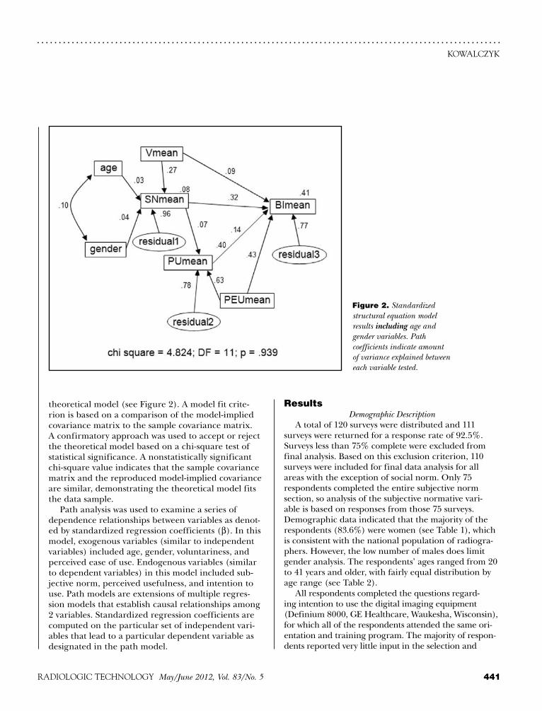
theoretical model (see Figure 2). A model fit crite-rion is based on a comparison of the model-implied covariance matrix to the sample covariance matrix. A confirmatory approach was used to accept or reject the theoretical model based on a chi-square test of statistical significance. A nonstatistically significant chi-square value indicates that the sample covariance matrix and the reproduced model-implied covariance are similar, demonstrating the theoretical model fits the data sample.
Path analysis was used to examine a series of dependence relationships between variables as denot-ed by standardized regression coefficients (β). In this model, exogenous variables (similar to independent variables) included age, gender, voluntariness, and perceived ease of use. Endogenous variables (similar to dependent variables) in this model included sub-jective norm, perceived usefulness, and intention to use. Path models are extensions of multiple regres-sion models that establish causal relationships among 2 variables. Standardized regression coefficients are computed on the particular set of independent vari-ables that lead to a particular dependent variable as designated in the path model.
resultsDemographic Description
A total of 120 surveys were distributed and 111 surveys were returned for a response rate of 92.5%. Surveys less than 75% complete were excluded from final analysis. Based on this exclusion criterion, 110 surveys were included for final data analysis for all areas with the exception of social norm. Only 75 respondents completed the entire subjective norm section, so analysis of the subjective normative vari-able is based on responses from those 75 surveys. Demographic data indicated that the majority of the respondents (83.6%) were women (see Table 1), which is consistent with the national population of radiogra-phers. However, the low number of males does limit gender analysis. The respondents’ ages ranged from 20 to 41 years and older, with fairly equal distribution by age range (see Table 2).
All respondents completed the questions regard-ing intention to use the digital imaging equipment (Definium 8000, GE Healthcare, Waukesha, Wisconsin), for which all of the respondents attended the same ori-entation and training program. The majority of respon-dents reported very little input in the selection and
Figure 2. Standardized structural equation model results including age and gender variables. Path coefficients indicate amount of variance explained between each variable tested.

. . . . . . . . . . . . . . . . . . . . . . . . . . . . . . . . . . . . . . . . . . . . . . . . . . . . . . . . . . . . . . . . . . . . . . . . . . . . . . . . . . . . . . . . . . . . . . . . . . . . . . . . . . .INFLUENCE OF GENDER, AGE, AND SOCIAL NORM
442 May/June 2012, Vol. 83/No. 5 RADIOLOGIC TECHNOLOGY
n Does a relationship exist between subjective norm and intention to use the technology in a man-dated health care environment?
The standardized path relationship between subjec-tive norm and intention to use the technology was β = 0.32. This indicates that subjective norm explained or predicted approximately one-third of behavioral inten-tion to use the technology.
n Does a relationship exist between subjective norm and perceived usefulness in a mandated health care environment?
The standardized regression coefficient assessing a relationship between perceived usefulness and subjec-tive norm was β = 0.07. This indicates that subjective norm did not significantly affect perceived usefulness.
n Does a relationship exist between voluntariness and intention to use the technology in a man-dated health care environment?
The standardized path relationship between inten-tion to use the technology and voluntariness is β = 0.09. This indicates that voluntariness does not significantly affect behavioral intention to use the technology.
Consistent with previous studies, perceived ease of use was the largest predictor of perceived usefulness and behavioral intention (see Table 3).
LimitationsSeveral limitations were acknowledged in this study.
First, the study population may not be representative of all radiographers certified by the American Registry
implementation of the digital imaging system. Only 6 individuals (5.5%) indicated they served in a leadership role regarding the adoption and selection of the digital imaging system. Sixteen respondents (14.5%) reported assisting in the implementation phase. However, almost half of the respondents (42.7%) reported having respon-sibility for user training of the digital imaging system. These results suggest that for the majority of respon-dents, the selection, adoption, and implementation of the digital imaging system was mandated by personnel at a higher organizational level.
Path AnalysisThe squared multiple correlation value (R2) indicates
the amount of variance explained, predicted, or account-ed for a particular endogenous variable by the set of exogenous predictor variables. Path analysis in this study specified the R2 value for subjective norm (the endog-enous variable) was 0.08, estimating that voluntariness, age, and gender accounted for or explained only 8% of subjective norm. The R2 value for perceived usefulness was 0.40, estimating that subjective norm and perceived ease of use accounted for 40% of perceived usefulness. The R2 value for intention to use technology was 0.41, indicating that the 4 variables — voluntariness, subjective norm, perceived usefulness, and perceived ease of use — accounted for or explained 41% of the radiographers’ intention to use the digital imaging system.
Research Questionsn Does a relationship exist between age and subjec-
tive norm in a mandated health care environment?The path model demonstrated a relationship between
subjective norm and age (β = 0.03). This indicates that age did not significantly affect subjective norm.
n Does a relationship exist between gender and subjective norm in a mandated health care envi-ronment?
The path model demonstrated a relationship between subjective norm and gender with β = 0.04. This indicates that gender did not significantly affect subjective norm. However, the low number of men (15.5%) who partici-pated in this study limited analysis of gender effects.
n Does a relationship exist between voluntariness and subjective norm in a mandated health care environment?
The path model demonstrated a relationship between subjective norm and voluntariness (β = 0.27). This indicates that voluntariness explained or predict-ed a small percentage of subjective norm.
Table 1 Self-Reported Gender of Respondents1
Gender n (%)
Male 17 (15.5)
Female 92 (83.6)
Missing 1 (0.9)
Table 2 Self-Reported Age of Respondents
Age Range in Years n (%)
20-30 39 (35.5)
31-40 42 (38.2)
41 27 (24.5)
Missing 2 (1.8)

. . . . . . . . . . . . . . . . . . . . . . . . . . . . . . . . . . . . . . . . . . . . . . . . . . . . . . . . . . . . . . . . . . . . . . . . . . . . . . . . . . . . . . . . . . . . . . . . . . . . . . . . . . .
443RADIOLOGIC TECHNOLOGY May/June 2012, Vol. 83/No. 5
KOwALCzYK
in terms of subjective norm (see Figure 3). In this scenario, voluntariness had a weak mediating effect, suggesting that other environmental factors play a larger role in explaining subjective norm in a radiologic environment. Therefore, one can conclude that additional contextual variables play a role in the radiographers’ intention to use the technology in a nonvoluntary environment.
One factor for this unexplained variance may relate to the occupational differences in this population com-pared to those populations previously studied.6 Earlier studies included individuals with various hierarchical positions within an organization. Sociocultural factors shown to influence technology adoption in the busi-ness sector include differences in income, education, and previous computer use. However, the population in this study was homogeneous; they were all staff radiog-raphers holding similar positions within the organiza-tion and had similar incomes, education, and com-puter skills. They self-selected to enter a health care profession driven by technology and were accustomed to working in an environment in which technologic changes are mandated frequently. All participants in this study also chose to pursue a career in a technical field that requires continual development of new skills to function in a modern imaging department.
This implies that in a homogeneous population, the context in which the knowledge is developed and
of Radiologic Technologists who use digital imaging equipment. Although a variety of imaging locations — including both inpatient and outpatient facilities —were included in the study, the generalizability of the results is limited to the study population.
Another limitation of this study is the variety of additional independent or exogenous variables affect-ing subjective norm that were not incorporated into this theoretical model. A review of the literature sug-gests that attitude, behavioral control, managerial and environmental resources, and training could be impor-tant factors relative to subjective norm. Unfortunately, a current model does not exist to account for all con-founding variables.
Additionally, the low number of male respondents limited the analysis of the impact of gender pattern-related relationships.
Discussion Although the data supports the modified versions
of TAM2, the relationship between age and gender was very low with β = 0.10. Therefore, one can conclude that radiographers are equally likely to use digital imaging equipment regardless of their age. Secondly, gender patterns did not apply to the adoption of technology for this population, men and women appear to be equally likely to use digital imaging equipment. It must be noted, however, that gender limitations were encountered because of the low number of men participating in this study. These results are contrary to previous research that suggests gender differences should be expected to vary based on age and that gender-based attitudes are more salient for older individuals (ie, older women would be less likely to adopt the technology). In this study, however, gender and age had no effect on the influence of perceived social pressure to use digital imaging equipment.11,19
The majority of previous TAM2 studies were conducted in the business sector (eg, insurance and banking), including samples with a wide range of organizational positions and functions. This is the first study to examine radiographers’ acceptance of technology using a standardized adoption model. It is important to note these results indicate that radiographers react differently to technology adoption in a mandated environment than do other populations.
Based on these findings, age and gender were removed from the acceptance model, leaving voluntariness as the only exogenous variable measured
Table 3 Standardized Regression Coefficients
Dependent/Independent Variables β Coefficient
SN mean ← age 0.030
SN mean ← gender 0.040
SN mean ← V mean 0.270
SN mean ← residual 1 0.961
PU mean ← SN mean 0.034
PU mean ← PEU mean 0.630
PU mean ← residual 2 0.771
BI mean ← V mean 0.113
BI mean ← SN mean 0.187
BI mean ← PU mean 0.155
BI mean ← PEU mean 0.487
BI mean ← residual 3 0.866

. . . . . . . . . . . . . . . . . . . . . . . . . . . . . . . . . . . . . . . . . . . . . . . . . . . . . . . . . . . . . . . . . . . . . . . . . . . . . . . . . . . . . . . . . . . . . . . . . . . . . . . . . . .INFLUENCE OF GENDER, AGE, AND SOCIAL NORM
444 May/June 2012, Vol. 83/No. 5 RADIOLOGIC TECHNOLOGY
intention.23,24 Given that age, gender, and voluntariness demonstrated little effect on social norm and behav-ioral intention in this population, pertinent variables to explore in future studies may be a measurement of attitude, domain-specific knowledge learned within the community of practice, shared professional orien-tation, participants’ experience, and training/facilitat-ing conditions.
ConclusionMultiple implications and recommendations are
identified consequential to this study. The adoption of a digital imaging system is a critical investment decision. Simply acquiring the technology is not a sufficient condition for effective use of the system. This study demonstrated that choosing a system with low perceived ease of use may have a dramatic effect on the perceived usefulness of the equipment, as well as the radiographers’ behavioral intention to use the equipment.
Second, attention must be given to managing change within the imaging department. To realize the expected benefits from digital imaging investments, the effect of social dynamics in the workplace on the adoption and
applied (ie, the culture of the com-munity of practice) may have a greater influence on subjective norm and intention to use a technology than an individual’s choice to use the techno-logic innovation does. Results of this study support the concept that the learner’s experiences cannot be sepa-rated from learning and cognition.20,21 Adopting the belief system of the com-munity in which the new technology is used is an integral and inseparable aspect of the social practice of radi-ography, suggesting that meaningful learning is connected to the social norm or the social and physical con-text within which the knowledge is used. Therefore, one can conclude that the community of practice must be considered when identifying those exogenous variables affecting subjec-tive norm and intention to use the technology.
Because radiographers are con-nected both by their professional prac-tice and through socially constructed beliefs essential to understanding their activities, the contextual factors within a particular organization will affect the use of the new knowledge. Therefore, one can conclude that technology acceptance models must be adapted to the particular culture of the popula-tion under study. Technology acceptance models must be specific to the context in which the learning and technology use take place. This suggests that a unified technology adoption model is not sufficient to explain intention to use technology and that each model must be adapted to the particular environment being tested to provide useful information.
Previous research suggested that attitude as an inde-pendent variable significantly affects subjective norm in a mandated environment because it represents the degree to which users are satisfied with the system.5,22 Individual differences in personality, demographic, and situational variables — including intellectual abilities, domain-specific knowledge, experience, edu-cation, professional orientation, and organizational level — were identified to have a critical role in subjec-tive norm.23 The implementation context (ie, social influence, training, and facilitating conditions) also were shown to have a great influence on behavioral
Figure 3. Standardized structural equation model results excluding age and gender variables. Path coefficients indicate amount of variance explained between each vari-able tested.

. . . . . . . . . . . . . . . . . . . . . . . . . . . . . . . . . . . . . . . . . . . . . . . . . . . . . . . . . . . . . . . . . . . . . . . . . . . . . . . . . . . . . . . . . . . . . . . . . . . . . . . . . . .
445RADIOLOGIC TECHNOLOGY May/June 2012, Vol. 83/No. 5
KOwALCzYK
use of innovative products is of paramount importance. Purchasing digital imaging equipment without consid-eration of the community of practice and the organiza-tional environment will not solve existing problems or create a competitive advantage. This study indicated that a relationship exists between subjective normative fac-tors in an environment where the use of digital imaging is mandatory. In turn, subjective normative factors also were shown to have a relationship to the radiographers’ behavioral intention. This suggests that an administra-tor’s ability to identify, predict, and manage employee acceptance of technology will facilitate implementation efforts and improve the ultimate success of the capital investment. Additional studies should be conducted to identify other exogenous variables affecting subjective norm. This knowledge may enable administrators to develop a medical imaging workforce that can respond to rapid technologic changes and to assess the impor-tance of careful employee selection and training and support of leadership, which is critical to maintain a change-oriented culture.
This study supports the concept that radiographers’ intention to use digital imaging equipment depends on social processes, as evidenced by the relationship between subjective norm and intention to use the technology. Thus, understanding the environment, resources, and culture are critical to successful adop-tion of digital imaging systems. Implementation of a new technology directly affects employees; therefore, vendors must place equal focus on humanistic and organizational issues and technological aspects of the project for a successful implementation. If the innova-tion creates a high degree of change or if employees have not been consulted prior to the adoption of the technology, they may resist the technologic change. Resistance also can increase in the postadoption stage if the system does not perform as expected or if it cre-ates a disruptive conflict in the workplace.1
Implications also are warranted for educators and trainers. Situated cognition theory states that moving from a novice user to a master user requires full par-ticipation within a community.20,21 From an educator’s perspective, it is important to note that a novice does not lack the ability to perform a task or skill; they lack the knowledge only accessible through experience within the community and the situation that permits concep-tualization of the knowledge. Adult learning is a social, interactive process in which the learner interacts with the learning environment. This theory is supported by the results of this study, which demonstrated that social
norm accounts for approximately one-third of the vari-ance explained in the intention to use new technology. Therefore, it is critical to understand the learners and the context in which the learning will occur most effec-tively. However, age and gender are demonstrated to have little effect on social norm in this population, suggesting that variables outside the scope of the modified TAM2 model play a significant role in social normative factors.
Although voluntariness, age, and gender have shown to have little to no affect on subjective norm — sug-gesting the models tested do not adequately identify variables pertinent to subjective norm in this popula-tion — this study does support the concept that social influence is an integral part of behavioral intention. Previous research suggests that attitude, training, and facilitating conditions have a significant influence on behavioral intention.23,24 In addition, the implementa-tion context and self-efficacy were identified as pri-mary factors in reducing anxiety in previous research. Therefore, providing a safe, interactive, context-based learning environment that acknowledges the unique adult population may positively affect radiographers’ intention to use new technology.23,24
references1. Ram S, Jung HS. Forced adoption of innovations in orga-
nizations: consequences and implications. J Prod Innovation Manage. 1991;8(2):117-126.
2. Carayon P, Karsh B. Sociotechnical issues in the imple-mentation of imaging technology. Behav Inf Tech. 2000;19(4):247-262.
3. Hartwick J, Barki H. Explaining the role of user par-ticipation in information system use. Manage Sci. 1994;40(4):440-465.
4. Agarwal R, Prasad J. The role of innovation characteristics and perceived voluntariness in the acceptance of informa-tion technologies. Decis Sci. 1997;28:557-582.
5. Brown SA, Massey AP, Montoya-Weiss MM, Burkman JR. Do I really have to? User acceptance of mandated technol-ogy. Eur J Inf Syst. 2002;11:283-295.
6. Venkatesh V, Davis FD. A theoretical extension of the tech-nology acceptance model: four longitudinal field studies. Manage Sci. 2000;46(2):186-204.
7. Rogers EM. Diffusion of Innovation. 4th ed. New York, NY: Simon & Schuster Inc; 1995.
8. Venkatesh V, Morris MG, Davis GB, Davis FD. User accep-tance of information technology: toward a unified view. MIS Q. 2003;27(3):425-478.
9. Yi MY, Jackson JD, Park J, Probst JC. Understanding infor-mation technology acceptance by individual professionals: toward an integrative view. Inf Manage. 2006;43:350-363.

. . . . . . . . . . . . . . . . . . . . . . . . . . . . . . . . . . . . . . . . . . . . . . . . . . . . . . . . . . . . . . . . . . . . . . . . . . . . . . . . . . . . . . . . . . . . . . . . . . . . . . . . . . .INFLUENCE OF GENDER, AGE, AND SOCIAL NORM
446 May/June 2012, Vol. 83/No. 5 RADIOLOGIC TECHNOLOGY
department in the School of Allied Medical Professions at The Ohio State University in Columbus. She also is chairman of the Radiologic Technology Editorial Review Board.
Reprint requests may be sent to the American Society of Radiologic Technologists, Communications Department, 15000 Central Ave SE, Albuquerque, NM 87123-3909, or e-mail [email protected].
©2012 by the American Society of Radiologic Technologists.
10. Mathieson K. Predicting user intention: comparing the technology acceptance model with theory of planned behavior. Inf Sys Res. 1991;2(3):173-191.
11. Venkatesh VV, Morris MG, Ackerman PL. A longitudinal field investigation of gender differences in individual tech-nology adoption decision-making processes. Organ Behav Hum Decis Process. 2000;83(1):33-60.
12. Venkatesh V, Morris MG. Why don’t men ever stop to ask for directions? Gender, social influence, and their role in technology acceptance and usage behavior. MIS Q. 2000;24(1):115-139.
13. Fishbein M, Ajzen I. Belief, Attitude, Intention and Behavior: Introduction to Theory and Research. Reading, MA: Addison-Wesley; 1975.
14. Davis FD, Bagozzi RP, Warshaw PR. User acceptance of computer technology: a comparison of two theoretical models. Manage Sci. 1989;35(8):982-1003.
15. Ajzen I. The theory of planned behavior. Organ Behav Hum Decis Process. 1991;50(2):179-211.
16. Moore GC, Benbasat I. Development of an instrument to measure the perceptions of adopting an information tech-nology innovation. Inf Sys Res. 1991;2(3):192-222.
17. Tung FC, Chang SC, Chou CM. An extension of trust and TAM model with IDT in the adoption of electronic logis-tics information systems in HIS in the medical industry. Int J Med Inform. 2008;77(5):324-335.
18. Davis FD, Venkatesh V. A critical assessment of potential measurement biases in the technology acceptance model: three experiments. Int J Hum-Comput Stud. 1996;45:19-45.
19. Morris MG, Venkatesh V, Ackerman PL. Gender and age differences in employee decisions about new technology: an extension of the theory of planned behavior. IEEE Trans Eng Manage. 2005;52(1):69-84.
20. Brown JS, Collins A, Duguid P. Situated cognition and the culture of learning. Educ Res. 1989;18(1):32-42.
21. Lave J, Wenger E. Situated Learning: Legitimate Peripheral Participation. New York, NY: Cambridge Press; 1991.
22. Agarwal R. Individual acceptance of information tech-nologies. In: Zmud RW, ed. Framing the Domains of IT Management Research: Glimpsing the Future Through the Past. Cincinnati, OH: Pinnaflex Educational Resources; 2000:84-104.
23. Aggelidis VP, Chatzoglou PD. Using a modified tech-nology acceptance model in hospitals. Int J Med Inform. 2009;78(2):115-126.
24. Duyck P, Pynoo B, Devolder P, Voet T, Adang L, Vercruysse J. User acceptance of a picture archiving and communica-tion system. Methods Inf Med. 2008;47(2):149-156.
Nina Kowalczyk, PhD, R.T.(R)(CT)(QM), FASRT, is an assistant professor in the radiologic sciences and therapy
erratumAn error occurred in the Directed Reading,
“Solid Organ Donation and Transplantation,” which appeared in the March/April 2012 issue. The liver and lung labels in Figure 2 were trans-posed. The error did not affect the post-test.
Thank you to the readers who brought this error to our attention.
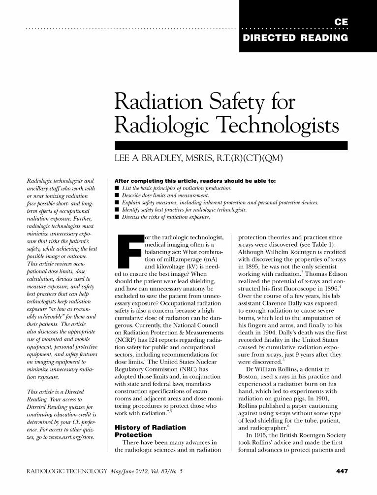
CE
DIRECTED READING. . . . . . . . . . . . . . . . . . . . . . . . . . . . . . . . . . . . . . . . . . . . . . . . . . . . . . . . . . . . . . . . . . . . . . . . . . . . . . . . . . . . . . . . . . . . . . . . . .
447RADIOLOGIC TECHNOLOGY May/June 2012, Vol. 83/No. 5
After completing this article, readers should be able to:n List the basic principles of radiation production.n Describe dose limits and measurement.n Explain safety measures, including inherent protection and personal protective devices.n Identify safety best practices for radiologic technologists.n Discuss the risks of radiation exposure.
Radiologic technologists and ancillary staff who work with or near ionizing radiation face possible short- and long-term effects of occupational radiation exposure. Further, radiologic technologists must minimize unnecessary expo-sure that risks the patient’s safety, while achieving the best possible image or outcome. This article reviews occu-pational dose limits, dose calculation, devices used to measure exposure, and safety best practices that can help technologists keep radiation exposure “as low as reason-ably achievable” for them and their patients. The article also discusses the appropriate use of mounted and mobile equipment, personal protective equipment, and safety features on imaging equipment to minimize unnecessary radia-tion exposure.
This article is a Directed Reading. Your access to Directed Reading quizzes for continuing education credit is determined by your CE prefer-ence. For access to other quiz-zes, go to www.asrt.org/store.
LEE A BRADLEY, MSRIS, R.T.(R)(CT)(QM)
Radiation Safety for Radiologic Technologists
For the radiologic technologist, medical imaging often is a balancing act: What combina-tion of milliamperage (mA) and kilovoltage (kV) is need-
ed to ensure the best image? When should the patient wear lead shielding, and how can unnecessary anatomy be excluded to save the patient from unnec-essary exposure? Occupational radiation safety is also a concern because a high cumulative dose of radiation can be dan-gerous. Currently, the National Council on Radiation Protection & Measurements (NCRP) has 124 reports regarding radia-tion safety for public and occupational sectors, including recommendations for dose limits.1 The United States Nuclear Regulatory Commission (NRC) has adopted those limits and, in conjunction with state and federal laws, mandates construction specifications of exam rooms and adjacent areas and dose moni-toring procedures to protect those who work with radiation.2,3
History of Radiation Protection
There have been many advances in the radiologic sciences and in radiation
protection theories and practices since x-rays were discovered (see Table 1). Although Wilhelm Roentgen is credited with discovering the properties of x-rays in 1895, he was not the only scientist working with radiation.3 Thomas Edison realized the potential of x-rays and con-structed his first fluoroscope in 1896.4 Over the course of a few years, his lab assistant Clarence Dally was exposed to enough radiation to cause severe burns, which led to the amputation of his fingers and arms, and finally to his death in 1904. Dally’s death was the first recorded fatality in the United States caused by cumulative radiation expo-sure from x-rays, just 9 years after they were discovered.5
Dr William Rollins, a dentist in Boston, used x-rays in his practice and experienced a radiation burn on his hand, which led to experiments with radiation on guinea pigs. In 1901, Rollins published a paper cautioning against using x-rays without some type of lead shielding for the tube, patient, and radiographer.6
In 1915, the British Roentgen Society took Rollins’ advice and made the first formal advances to protect patients and

CERADIATION SAFETY
448 May/June 2012, Vol. 83/No. 5 RADIOLOGIC TECHNOLOGY
. . . . . . . . . . . . . . . . . . . . . . . . . . . . . . . . . . . . . . . . . . . . . . . . . . . . . . . . . . . . . . . . . . . . . . . . . . . . . . . . . . . . . . . . . . . . . . . . . .
radiation production and characteristics, radiation biology, and radiation protection.9
Basic Radiation PrinciplesRadiation is the act of emitting energy in the form
of photons or particles.10 It is considered “ionizing” when the energy can produce changes in atomic struc-ture by creating positively or negatively charged atoms. The types of ionizing radiation used in a diagnostic imaging department are x-rays, gamma rays, and beta particles. The nature of the images sought determines the type of radiation used.
The AtomWhen most people picture an atom, they think
of the structure described by Niels Bohr in 1913 — a dense nucleus housing protons and neutrons, sur-rounded by electrons moving in elliptical paths. These ellipses are called shells; the shell closest to the nucleus is the K-shell, with successive shells L through Q avail-able depending upon the element. Each shell has a pre-determined maximum number of electrons that can be calculated by using the quantity 2n2, where n equals the shell position from the nucleus; the outermost shell always has a maximum of 8 allowable electrons. As an example, an oxygen atom contains 8 electrons. If the K-shell is allowed only 2 electrons (2[1]2), the atom must have at least an L-shell to house the other 6 electrons. In a stable atom there are enough shells con-taining negatively charged electrons to balance out the number of positively charged protons in the nucleus. A neutron has no charge.5
Electrons are held within their orbit by “binding energy.” An atom is termed an ion if the number of electrons in the atom changes from its stable configura-tion. Ionizing radiation is any radiation capable of over-coming the binding energy and knocking an electron from its shell.5
Types of RadiationRadiology modalities use different types of ion-
izing radiation. X-rays are created when an outside source bombards a target with an artificially created stream of electrons. The transfer of energy from the electron stream to the innermost electrons of the tar-get’s atoms creates x-ray photons with characteristics that identify the target material used. The resulting photons are known as characteristic x-ray photons. However, if the electron stream interacts with the nucleus of a target atom instead of the electrons, it
medical radiation workers by adopting a resolution recommending that x-ray tubes be shielded with lead.5,7 In 1934, the U.S. Advisory Committee on X-ray and Radium Protection, now known as the NCRP, issued the first report of recommended maximum exposures. NCRP Report 116, published in 1993, set the current public and occupational dose limits for exposure to ionizing radiation.1
ALARA, or “as low as reasonably achievable,” is the principle used today to help manage both patient and occupational radiation exposure. To help radio-logic technologists adhere to the ALARA principle, the American Society of Radiologic Technologists (ASRT) maintains a recommended radiography program curriculum that focuses on radiation pro-duction and safety. The ASRT published its first recommended radiography curriculum in 1952 and has continually modified it to keep up with advances in knowledge and technology.8 The current curricu-lum, adopted for use beginning in 2012, includes an introduction to radiologic science and health care,
Table 1Timeline of Radiation Discovery and Safety Measures
Date Event
1895 Wilhelm Roentgen discovers x-rays.
1896 Thomas Edison develops first fluoroscope.
1901 William Rollins recommends lead shielding.
1904 Clarence Dally dies from cumulative radiation exposure from x-rays (first recorded radiation-related death in the United States).
1913 Niels Bohr publishes theory of atom design.
1915 The British Roentgen Society adopts resolu-tion to use lead shielding.
1934 U.S. Advisory Committee on X-ray and Radium Protection issues first recommenda-tion for dose limits.
1952 American Society of Radiologic Technologists (ASRT) issues first radiogra-phy program curriculum recommendation.
1993 National Council on Radiation Protection & Measurements issues dose limits used today.
2012 ASRT introduces latest radiography program curriculum recommendation.

CEDIRECTED READING
. . . . . . . . . . . . . . . . . . . . . . . . . . . . . . . . . . . . . . . . . . . . . . . . . . . . . . . . . . . . . . . . . . . . . . . . . . . . . . . . . . . . . . . . . . . . . . . . . .
449RADIOLOGIC TECHNOLOGY May/June 2012, Vol. 83/No. 5
result is a scattered x-ray and a Compton electron (a Compton pair) with a combined energy equaling that of the incident photon. Either one also can interact with more tissue. The Compton effect could happen with any x-ray photon, but it is more likely to occur as the energy of the incident photon increases. The scat-ter produced by the Compton effect is considered iso-tropic, meaning it can travel in any direction from its point of origin. For example, if a patient is positioned for a posteroanterior chest radiograph, a Compton pair may scatter forward, backward, or to the side.3 Technologists can avoid Compton effect scatter from a single radiograph if they are in a control booth with shielding or stand at a sufficient distance from poten-tially dangerous scatter. However, large amounts of scatter produced by patients during fluoroscopy can contribute to occupational radiation dose.
The photoelectric effect occurs when an incident photon interacts with a K-shell electron. The photon knocks the electron from its orbit and releases all of its energy; the new “photoelectron” has energy equal to the incident photon minus the binding energy of the original electron. The binding energy of the K-shell of human tissue is relatively low. Therefore, the photoelectron created during the photoelectric effect can continue to interact with other atoms within the patient, causing an increase in patient dose. Because of the vacancy in the K-shell created by the expulsion of the photoelectron, the original atom is now unstable. Electrons in successive shells now drop into the open spots, creating what is called characteristic radiation.3 It is this characteristic radiation that contributes useful information to a radiographic image.
Measuring Radiation ExposureRadiation exposure is measured in a variety of
ways, depending on the nature of the radiation and the reason behind the measurement. Two different tables are in use: conventional (British) units and the International System of Units (SI). These 2 systems are not directly equivalent (see Table 2).
In diagnostic radiography and computed tomogra-phy (CT), the basic measurement of radiation intensity is the roentgen (R), or coulomb/kilogram (C/kg [SI unit]). The measurement represents the amount of radiation produced before it interacts with an object and is based upon the potential damage of any particu-lar dose of radiation to human tissue. The radiation intensity of diagnostic x-rays is generally measured in milliroentgens (mR).5
produces bremsstrahlung radiation. A bremsstrah-lung photon is created when an electron from the stream passes close enough to the target nucleus to be affected by its electrical field, or when it collides with the nucleus. Either interaction will result in a loss of energy by the incoming electron. This loss of energy becomes the new photon.5
Nuclear medicine uses beta particles and gamma rays rather than x-rays. A beta particle is created when an unstable isotope with too many neutrons emits an electron from its nucleus in an attempt to reach a state of stability. Gamma rays carry the same properties as x-rays, including ionization; however, they originate from the nucleus of an atom after either an electron or a positron (a positively charged electron) is emitted from it. The creation of both gamma rays and beta par-ticles is considered radioactive decay or disintegration.5
Effects of X-rays on MatterThe x-ray tube used in diagnostic radiography
consists of a negatively charged cathode that emits a high-powered stream of electrons toward a rotating, positively charged anode. The electrons react with the atoms of the anode, creating x-ray photons that are directed by the rotation of the anode through a glass window toward the subject to be imaged. The original stream of photons produced is called the incident x-ray or primary beam.
Within the diagnostic radiography range of kilo-volts (kV), x-ray photons can interact with human tissue in 3 ways:
n Coherent scattering. n Compton effect. n Photoelectric effect. Coherent scatter (ie, Thomson, classical, or unmodi-
fied scatter) results when a low-energy incident photon causes tissue atoms to vibrate. An atom may absorb the incident photon and then expel a scattered photon with a change in direction but no change in energy. The scattered x-ray — at such low kV — does not change the composition of tissue atoms, so it is not considered ioniz-ing radiation. Coherent scatter does not increase patient or technologist dose and does not provide any useful diagnostic information, but it can cause fogging on film or an image receptor.11
Scatter radiation produced by the Compton effect presents the greatest danger to technologists. The Compton effect occurs when an incident photon inter-acts with an outer-shell electron from the patient (or other human tissue) and knocks it from its orbit. The

CERADIATION SAFETY
450 May/June 2012, Vol. 83/No. 5 RADIOLOGIC TECHNOLOGY
. . . . . . . . . . . . . . . . . . . . . . . . . . . . . . . . . . . . . . . . . . . . . . . . . . . . . . . . . . . . . . . . . . . . . . . . . . . . . . . . . . . . . . . . . . . . . . . . . .
medicine is mea-sured in millicuries, the damage potential equals that of x-rays. So, the equivalent dose potential of radioactive isotopes is expressed in roent-gen or radiation equivalent man (see Table 2).5,12,13
Measurement DevicesThe NRC man-
dates that all workers who are routinely exposed to radiation be monitored so they do not exceed the annual dose limits set forth by the NCRP.2,14 The most common way to measure occupational exposure in a radiology department is through personal dosimeters such as a film badge, thermoluminescent dosimeter (TLD) or an optically stimulated luminescence whole-body dosimeter (OSL).
A typical film badge is a small piece of plastic that contains metal filters and film. The filters interact with radiation received by the wearer and leave an impression on the film. Film badges are a reliable way to track dose for all types of radiation used in a hospital setting and begin detecting radiation exposure at 10 mR and higher. They are relatively inexpensive, but inadvertent exposure to humidity or temperature can damage the film.5
A TLD is similar in size and shape to a film badge but works in an entirely different way. Instead of film, a TLD uses lithium fluoride crystals that react with radia-tion by exciting electrons and keeping them within a framework. When heated, the electrons drop from their frame and emit light. This light is measured to estimate the amount of radiation exposure. TLDs are more sensitive and more accurate than film badges — down to 5 mR — but they can cost up to twice as much as film badges.3
An OSL dosimeter is similar in function to a TLD with the exception that, when read, the crystals within are stimulated by the light of a laser instead of by heat. OSLs also can be read more than once, if a reading needs to be verified, and are capable of measuring x-ray exposure to 1 mrem.15,16
The technologist is responsible for wearing his or her dosimeter in the proper place at all times during work hours and only when working. Any dose absorbed outside of work is considered nonoccupational radiation
Within the diagnostic department, patient dose is measured in radiation absorbed dose (rad) or grays (Gy [SI unit]), and occupational dose is measured in radiation equivalent man (rem) or sieverts (Sv [SI unit]). Radiation absorbed dose reflects the amount of radiation a person or body part absorbs as the x-ray photon passes through the body. The rem is based on the expected biologic effect of a specific type of radia-tion exposure. Within the diagnostic radiography spec-trum, 1R = 1 rad = 1 rem. However, this is not true for all types of radiation.5
An isotope is an atom that has the same number of protons and electrons as an element, but differs in the number of neutrons; for some isotopes the change in neutrons makes them automatically attempt to com-pensate. “Disintegration” describes when the nucleus of an unstable isotope emits a particle to approach stabil-ity. Radioactive isotopes such as those used in nuclear medicine are discussed in terms of curie (Ci) or bec-querel (Bq [SI unit]). The curie and becquerel are measurements of the quantity of material — not the amount of radiation it may produce — which defines its radioactivity. A curie is the amount of a particular isotope needed to produce 3.7 × 10¹⁰ disintegrations per second. A becquerel is only 1 disintegration; so, 1 Ci equals 3.7 × 10¹⁰ Bq. One curie is not equal to 1 R or 1 rad or 1 rem. Patient doses in nuclear medi-cine are in the millicurie (mCi) range.11
Relative Biologic EffectivenessThe potential damage of any type of ionizing radia-
tion on human tissue is expressed as relative biologic effectiveness (RBE). Diagnostic x-rays, gamma rays, and beta particles are each assigned an RBE of 1. Although radioactive material used in nuclear
Table 2Measuring Radiation
Conventional Unit SI Unit Conversion Factor
Application
roentgen (R) coulomb/kilogram (C/kg)
1 R = 2.58 × 10⁻⁴ C/kg
Primary beam intensity
radiation absorbed dose (rad) gray (Gy) 1 rad = 0.01 Gy1 Gy = 100 rad
Patient dose
radiation equivalent man (rem) sievert (Sv) 1 Sv = 100 rem Occupational dose
curie (Ci) becquerel (Bq) 3.7 × 10¹⁰ Bq Radioactivity

CEDIRECTED READING
. . . . . . . . . . . . . . . . . . . . . . . . . . . . . . . . . . . . . . . . . . . . . . . . . . . . . . . . . . . . . . . . . . . . . . . . . . . . . . . . . . . . . . . . . . . . . . . . . .
451RADIOLOGIC TECHNOLOGY May/June 2012, Vol. 83/No. 5
Embryo exposure is not differentiated between radia-tion workers and the general public. The total gestational dose limit is 500 mrem (5 mSv). Dose limit for each month of the pregnancy is 50 mrem (0.5 mSv).2,19
The U.S. Department of Energy maintains a chart of dose comparisons compiled from research by Noelle Metting, ScD, that puts these doses into perspective. According to the chart, a chest radiograph delivers a dose of approximately 10 mrem to 20 mrem, and a den-tal exam delivers 160 mrem. Natural background radia-tion in the United States is listed at 300 mrem (this total includes radon) and the typical airliner crew is exposed to an average yearly dose of 200 mrem to 400 mrem out of the yearly 1000-mrem limit (see Tables 3 and 4).20
Potential Effects of Ionizing RadiationWhen discussing the deleterious effects of radiation,
the accepted theory is a linear nonthreshold model: the higher the radiation exposure, the more damage it can produce.21 When using this model, any dose of radiation can be harmful. Generally, potential effects of radiation are discussed in terms of acute vs chronic exposure and whole-body vs localized exposure.
and should not be included in occupational monitoring. Badges should be worn at waist or chest level under nor-mal circumstances. If the technologist is wearing a lead apron, he or she should wear the badge at neck level to get an accurate reading for exposed anatomy, such as the eyes. Pregnant technologists should wear a second dosim-eter at waist level. When wearing lead, the technologist should place the abdominal dosimeter under the shield.3 There are also extremity dosimeters, or ring badges, that generally are worn by nuclear medicine technologists because their hands may be subjected to direct radiation exposure (see Figure 1).
Film badges or TLDs are collected monthly or quarterly by 1 designated person within the radiol-ogy department, usually the radiation safety officer or quality manager. The dosimeters are sent to an outside company that processes them and prepares a report for the radiation safety officer.3 Per NRC regulations, all employees are allowed to see their reports.17 If there are any suspicious spikes in radiation, the radiation safety officer will try to determine a specific cause and counsel the employee.
Dose LimitsOccupational dosimetry is mandated by the NRC to
keep radiation exposure within the limits recommended by NCRP Report 116.1 The general public should be lim-ited to a yearly whole-body dose of 500 mrem (5 mSv). Radiation workers are allowed 10 times more radiation, for a total body dose of 5000 mrem (50 mSv). However, there is also a cumulative occupational dose limit in effect of 1000 mrem (10 mSv) times age in years.1 For example, if a radiologic technologist is 35 years old, his or her total exposure should not be more than 35 000 mrem (350 mSv). The radiation safety officer must make available a cumulative occupational dose history form if requested by a technologist.12,18
Yearly dose limits for specific body parts are based on their radiosensitivity and susceptibility to damage from ionizing radiation. These limits are based on the work of 2 scientists who described the phenomenon. The Law of Bergonie and Tribondeau states that radiosensitivity of a cell is determined by 4 factors: differentiation, age, activ-ity rate, and rate of mitosis. Stem cells, younger cells, very active cells, and rapidly dividing cells are more radiosensi-tive than differentiated, older, dormant, or dead cells.5 The dose limits for adults who work in any field contain-ing a regular and continuous chance of exposure to radia-tion are 15 rem (0.15 Sv) to the lens of the eye and 50 rem (0.5 Sv) to the extremities or skin of the entire body.2
Figure 1. Ring badge (A), thermoluminescent dosimeter (B), and film badge (C).
A
B
C

CERADIATION SAFETY
452 May/June 2012, Vol. 83/No. 5 RADIOLOGIC TECHNOLOGY
. . . . . . . . . . . . . . . . . . . . . . . . . . . . . . . . . . . . . . . . . . . . . . . . . . . . . . . . . . . . . . . . . . . . . . . . . . . . . . . . . . . . . . . . . . . . . . . . . .
Severe EffectsSevere effects of radiation exposure can manifest for
either a specific body part or system, or for the entire body. No damage occurring below a dose of 5 rad has been documented.5 For acute exposure, the smaller the area exposed, the more radiation needed to cause measurable damage. Whole-body radiation exposure of 5 rad or more can cause chromosomal changes, whereas 10 rad are needed to affect gonadal function. Reddening of the skin (erythema) can occur in a small area exposed to 200 rad, and hair loss (epilation) to a comparably sized area can occur at 300 rad. The entire body can be exposed to lower doses with localized effect (eg, cell counts), but if left untreated, a whole-body exposure of 600 rad or more will result in death.5
The severity of the effects of acute radiation expo-sure follows a documented pattern of symptoms based upon the dose received. The prodromal period, direct-ly after exposure of 100 rad or more, is characterized by nausea, vomiting, and diarrhea. This period may be followed by a latent period in which the exposed person does not show any outward symptoms. If the dose received is between 200 rad and 1000 rad, mani-fest illness begins with a return of the nausea, vomit-ing, and diarrhea, and includes cell count changes in the blood. Exposures of 1000 rad to 5000 rad lead to lethargy and shock, followed by symptoms of damage to the central nervous system at exposures greater
than 5000 rad.5 The progression of exposure to death can take anywhere from approximately 3 to 60 days, depending upon the whole-body dose.
Long-term Effects of Acute ExposureAtomic bomb survivors are a unique population
that scientists observe to determine the effects of short-term exposure over an extended period of time. The Radiation Effects Research Foundation (RERF) is a cooperative effort between Japan and the United States to track statistical evidence of cancer and other diseases in the survivor population. According to RERF, incidence of radiation-induced cancer coincides with the age at exposure and the time elapsed since exposure. RERF statistics indicate that the younger the age at exposure, the higher the incidence of cancer, which follows the Law of Bergonie and Tribondeau. However, for those victims who lived more than 20 years past the bomb, risk of leukemia became equal to that of the nonirradiated population.3,5,22
Chronic Medical ExposureChronic exposure to ionizing radiation, even at
low doses, has been shown to lead to several health conditions. Cataracts, leukemia, and several types of cancer have been linked to radiation exposure in certain populations, including radiation physicists and early radiologists who practiced before modern safeguards were in use. Clusters of thyroid, bone, and breast cancers have been attributed to the overzealous use of radiation treatment for thymus enlargement, ankolysing spondylitis, and postpartum mastitis.5
Acute Medical ExposureIt is an unfortunate truth that some patients are
over-radiated in the name of diagnostic imaging. Although the benefits generally far outweigh the risks, there are documented cases of patients suffering ery-thema, epilation, or worse because of fluoroscopy or similar imaging procedures.23
Protection for TechnologistsThe National Institutes of Health is conducting
research on the risks of developing cancer from occu-pational radiation. With the exception of a possible but still unproven link to breast cancer, modern radio-logic technologists (as of 1983) are at no greater risk for cancer than nonradiation workers.24 However, fol-lowing radiation safety guidelines is crucial.
Table 3 Occupational Dose Limits1
Occupational Dose Limits mrems
Yearly 5000
Cumulative 1000 × age in years
Lens of the eye 15 000
Extremities/whole skin 50 000
Table 4Approximate Radiation Dose20
Radiation Exposure mrem
Chest radiograph 10-20
Dental exam 160
Natural background radiation 300
Airline crew (yearly dose) 200-400

CEDIRECTED READING
. . . . . . . . . . . . . . . . . . . . . . . . . . . . . . . . . . . . . . . . . . . . . . . . . . . . . . . . . . . . . . . . . . . . . . . . . . . . . . . . . . . . . . . . . . . . . . . . . .
453RADIOLOGIC TECHNOLOGY May/June 2012, Vol. 83/No. 5
The working technologist has 3 types of protection from radiation exposure:
n Inherent protection provided in equipment con-struction and workspace design.
n Personal protective equipment. n Understanding the nature of radiation and the
inverse square law.
Inherent ProtectionThe construction of diagnostic imaging equipment
includes several elements designed to help keep a tech-nologist’s annual dose under the 5000-mrem (50 mSv) limit set by the NRC.2 The housing of an x-ray tube must be sufficient to absorb any radiation not included in the primary beam so the leakage from the housing at a distance of 1 m does not exceed 100 mR/hr (1 mGy/hr). If initial construction material is not sufficient, extra filtration can be added. The entire filtration for any x-ray tube above 70 kVp (which most multipurpose tubes are) must be equivalent to 2.5 mm of aluminum.5 The x-ray tube also has a set of collimators, or shutters, which not only helps direct the primary beam, but also absorbs any radiation not acutely focused on the patient.
Radiation protection is a construction component of any room designated for use with radiation equip-ment. Two types of barriers, primary and secondary, coincide with protection from either the primary beam or secondary scatter. The primary beam is the photon energy directed from the x-ray tube through a patient to an image receptor. The beam is given the most consid-eration because it contains the highest amount of radia-tion. Any wall (including floors and ceilings where appli-cable) perpendicular to the path of the x-ray beam must have at least the equivalent filtration of 1/16 in of lead; this is considered a primary barrier. Secondary barriers are used to protect technologists and incidental person-nel from scatter radiation coming from the tube, beam, or patient. Secondary barriers can be equal to half that of a primary barrier, or the equivalent of 1/32 in of lead.3 Both primary and secondary barriers can be constructed of any material, as long as the thickness used provides the needed filtration.
Workload and Occupancy FactorsSeveral factors are considered when deciding how
much protection is built into a particular room. The workload factor relates to how often the room is used for radiation work and general kilovolt levels used. The occupancy factor refers to the use of rooms adjacent to a radiation workspace, who is using them
(radiation worker, nonradiation worker, or the pub-lic), and possibility of exposure. The calculations for these and recommended construction information are included in reports 49 and 102 from the NCRP.25,26
Personal ProtectionRadiologic technologists do not have to think about
inherent protection because it is a built-in safety feature in all radiology departments. However, technologists can take steps to further protect themselves from primary and secondary radiation.
Mobile ShieldingA mobile shield is a vertical piece of Plexiglass or
metal on wheels. It can be positioned so that a tech-nologist or other personnel can step behind it during a fluoroscopic procedure or radiographic exposure when a lead apron is not available or practical. These devices should contain between 0.5 mm and 1.0 mm of lead equivalent to absorb scatter radiation sufficiently. Mobile shields are particularly useful in the operating room when 1 diagnostic image is being taken, but they are not practical for use with a C-arm.3
Personal ShieldingThe term “lead shield” can be misleading because
many shields are no longer made of lead, but instead a lighter weight composite of other metals (eg, tung-sten or tin) at a thickness to be equivalent to the properties of lead.27 The term is used in this article with the understanding that, in some cases, it may refer to shielding that comprises lead equivalent com-posites rather than lead.
Lead shields come in different shapes and sizes to protect certain body parts. The most frequently used shield is the body apron, which must be at least a lead equivalent of 0.25 mm.3,5 The apron is used to protect the bulk of the chest area down through the gonads on the anterior side. Aprons generally have straps with buckles or Velcro to secure the sides, but some have wrap-around straps that place less stress on the shoulders and back. Because aprons only protect the wearer from the front, a technologist should never turn his or her back to the primary beam or patient, who may emit scatter.
The same lead equivalents apply to vest and skirt shielding, which can be used during fluoroscopy (see Figure 2). This pairing provides full protection for the chest to the gonads, both front and back, and sides. Compared with an apron alone, the extra protection of

CERADIATION SAFETY
454 May/June 2012, Vol. 83/No. 5 RADIOLOGIC TECHNOLOGY
. . . . . . . . . . . . . . . . . . . . . . . . . . . . . . . . . . . . . . . . . . . . . . . . . . . . . . . . . . . . . . . . . . . . . . . . . . . . . . . . . . . . . . . . . . . . . . . . . .
However, maintaining distance from the source of the scatter is the easiest way for technologists to protect themselves.
A technologist’s radiation exposure can be calculated using the inverse square law:
I1/I2 = (D2/D1)2
where I = intensity of the beam and D = distance from the source. By doubling their distance from the source, technologists can reduce their exposure to one-fourth the original dose (see Box).11
Considerations by ModalityDuring their initial education, radio-
logic technologists are taught that time, distance, and shielding are the best ways to protect themselves from radiation
exposure and adhere to the ALARA principle. If tech-nologists spend as little time as possible near radiation, stand as far as possible from the source, and use shield-ing, their occupational dose should stay relatively low. However, special considerations should be taken into account, depending upon the modality.
Diagnostic RadiographyModern radiography departments may use com-
puted radiography (CR), digital radiography (DR), or film cassettes, and often some combination of the 3. Regardless of how the image is captured, the radiation
the vest-skirt combination increases the weight of shield-ing and might be a consideration for the technologist.
Because of the “one size fits all” approach, lead aprons and vests may fit loosely and generally do not fully protect the thyroid, a butterfly-shaped gland that sits above the sternal notch in the anterior neck and chest. This gland is sensitive to radiation and should be shielded whenever possible with a thyroid shield with 0.5 mm lead equivalent or greater (see Figure 3).3 A thyroid shield is fairly lightweight, wraps around the neck, and is secured in the back with Velcro.
Although radiologic technologists should avoid intersecting the primary beam if possible, sometimes it is unavoidable, especially during fluoroscopy. During upper gastrointestinal exams, for example, a technolo-gist may need to help patients turn over or hand them barium to drink during the test. In these cases, the technologist should wear lead-lined gloves to protect his or her hands and wrists. These gloves must have at least a 0.25 mm lead equivalent.3
Additionally, protective eyewear should be worn during fluoroscopic procedures or when intersect-ing the primary beam. Slightly heavier than regular glasses, protective eyeglasses should have side panels of leaded glass and must have 0.5 mm of lead equiva-lent (see Figure 4).3
Inverse Square LawTime, shielding, and distance are cardinal rules of
radiation protection. Understandably, limiting expo-sure time helps minimize dose, and shielding protects the technologist from low-dose scatter radiation.
Figure 2. Wrap-around skirt and vest shielding.
BoxCalculating Radiation Exposure11
Technologists can reduce their exposure to one-fourth the original dose by doubling their distance from the source. For example, if a technologist stands 1 ft from the source of radiation, where the intensity is 10 mR, and then moves back another foot from the source, the equation to find the new intensity of the beam can be calculated using the inverse square law:
Square the right side and multiply both sides by x: 10 mR = 4x
and divide both sides by 4 to get the new intensity of the beam:
2.5 mR = x
I1I2 12
dd
2221
10mR 22
x= =

CEDIRECTED READING
. . . . . . . . . . . . . . . . . . . . . . . . . . . . . . . . . . . . . . . . . . . . . . . . . . . . . . . . . . . . . . . . . . . . . . . . . . . . . . . . . . . . . . . . . . . . . . . . . .
455RADIOLOGIC TECHNOLOGY May/June 2012, Vol. 83/No. 5
the technologist to watch the patient without being exposed to radiation.
Basic radiography rooms are used for many types of examinations, and generally the x-ray tubes can be pointed in any direction. The technologist is respon-sible for ensuring the tube is never pointed at an open doorway, the control booth wall or window, or anything other than the image receptor. Also, focusing the beam collimators and using the smallest field of view necessary ensures that the patient and technologist are exposed to the least amount of radiation possible.
If a patient needs help remaining still during an exam, patient restraint devices can be used instead of having a staff member hold the patient in place. Some exam tables have safety straps, and wall units may have stabilization bars. Most diagnostic radiography depart-ments also have sandbags that can be used for several purposes, including:
n Weighing down a patient’s arms for a cervical spine study.
n Securing a pole the patient is holding for stabili-zation.
n Keeping an extremity in a particular position. Adhesive tape only should be used as a last resort to
keep a patient or body part still, and only if the patient gives consent.
If personal assistance is necessary, a member of the patient’s family should be the first choice to remain in the room with the patient during an exam, provided the relative is not pregnant and does not suspect she may be. If family is unavailable, a hospital employee who
used for any type of radiography is the same. Although the chosen imaging method may affect patient dose, the same types of protection apply for radiologic tech-nologists regardless of the imaging method.
The control booth is a safe area behind secondary barriers; if the construction of the room is up to code, any radiation in this area will be held to a maximum of 100 mrem (1 mSv) per week.3 The control panel for the x-ray tube contains exposure controls and an exposure button that may be connected by a cord so the technologist can hold it in his or her hand. The cord should not be long enough to allow the technolo-gist to enter the imaging room while making an expo-sure. For the safety of both technologist and patient, there should be a leaded glass window that allows
Figure 3. Marilyn Rivera, R.T.(R)(CT), wearing a lead apron, thyroid shield, and dosimeter.
Figure 4. Thyroid shield and leaded eyewear.

CERADIATION SAFETY
456 May/June 2012, Vol. 83/No. 5 RADIOLOGIC TECHNOLOGY
. . . . . . . . . . . . . . . . . . . . . . . . . . . . . . . . . . . . . . . . . . . . . . . . . . . . . . . . . . . . . . . . . . . . . . . . . . . . . . . . . . . . . . . . . . . . . . . . . .
aluminum equivalent between the tube and the patient to absorb low-dose x-rays, which can increase patient dose without providing additional diagnostic value.
If the tube is located within the table, the tower is situated above the patient — or in front of the patient if the table is positioned vertically — and contains the image intensifier or receptor. Considered a primary barrier, the tower requires at least 2 mm of lead equiva-lent shielding. The table contains a Bucky tray to hold a cassette for a single image; when fluoroscopy is used, the tray is moved to the patient’s feet so the opening in the side of the table is shielded by the tray’s slot cover,
generally is not exposed to occupational radiation (eg, a nurse) can help. Radiologic technologists should be the last choice to help a patient stay still during an examina-tion. Finally, whoever remains with the patient in the exam room for this purpose — hospital staff member or not — should be advised of possible radiation exposure and should be given a minimum of a lead apron and a thyroid shield, with leaded eyewear if needed.
Portable RadiographyIf a patient is not able to come to the imaging depart-
ment, basic radiographs can be taken using portable radiography equipment. The technical factors used in portable imaging may be slightly lower than on a fixed machine (eg, using 95 kV without a reciprocating grid compared to 120 kV with a reciprocating grid), but the technologist generally does not have the opportunity to leave the room and take the exposure remotely. To ensure the technologist’s safety, the cord to the expo-sure button on a portable machine must be at least 6 ft (approximately 2 m) long. Each portable x-ray machine should have a hook or storage place for a lead apron, which technologists always should wear when perform-ing portable exams. Additionally, the technologist should stand at least 6 ft from the patient and at a 90° angle from the primary beam, where there is the least amount of scatter (see Figure 5).3
FluoroscopyFluoroscopic units are located in diagnostic imaging
departments and generally are used for studies involving ingested or inserted barium, or for needle placement such as a myelogram. The table can be positioned hori-zontally so that the patient lies prone or supine, or it can be tilted vertically to allow the patient to be examined in an upright position. Whereas radiography is static, fluoroscopy is dynamic because it uses x-rays to show real-time images during a procedure. A general fluoro-scopic study uses the same x-rays as a regular tube, but it involves a continuous projection of the primary beam instead of 1 exposure. Per NCRP Report 102 require-ments, the maximum allowable rate of radiation expo-sure at a fluoroscopy unit’s tabletop is 10 mR/minute. This can raise the patient’s dose significantly, which can ultimately raise the technologist’s dose.26
Fluoroscopy equipment has built-in protection. Traditionally, the x-ray tube is located within the table. Although some models have the x-ray tube over the table, both types have the requisite housing to prevent radiation leakage. There must be at least 2 mm of
Figure 5. Portable x-ray machine with 6-ft exposure cord and hook for lead apron.

CEDIRECTED READING
. . . . . . . . . . . . . . . . . . . . . . . . . . . . . . . . . . . . . . . . . . . . . . . . . . . . . . . . . . . . . . . . . . . . . . . . . . . . . . . . . . . . . . . . . . . . . . . . . .
457RADIOLOGIC TECHNOLOGY May/June 2012, Vol. 83/No. 5
a full lead vest and skirt, thyroid shield, and leaded glasses. If full vests and skirts are not available, technol-ogists should wear aprons and pay special attention not to turn their backs toward the primary beam or patient because the physician could initiate the primary beam at any time. Although lead gloves may not be practical for tasks that require dexterity, they should be worn if a technologist’s hands will make contact with the pri-mary beam or the patient (ie, holding the barium for the patient to drink during the exam).
Operating RoomSeveral routine procedures in the operating room
(OR) require a radiologic technologist’s assistance. Plain radiographs often are used to check the location of a needle in spinal surgery or to perform a quick cholangiogram after stent placement. The biggest adjustment when using a portable machine in the OR is beam intensity. Because of the sterile surgical site and surrounding area, the intensity of the beam may need to be increased or decreased to compensate for changes in source-to-image distance or object-to-image distance. The technologist always should use a mobile shield or wear a lead apron and extend the full length of the 6-ft cord on the exposure button to ensure the lowest occupational dose.
Similar to a portable fluoroscopy machine, a mobile C-arm also is used in the OR. It is shaped like a “C,” with the x-ray tube mounted on the bottom curve and the image intensifier/receptor on the top curve.11 This unit can be useful in the OR for both static and real-time imaging of fixation screws, pacemaker lead place-ment, or angiographic work. A C-arm can be draped for sterility and moved over or under the patient, rather than moving the patient. The challenge for technolo-gists is keeping track of the x-ray tube — and therefore the direction of the primary beam — as its mobility means it can irradiate the patient and surrounding per-sonnel from almost any direction.
A C-arm generally has 2 basic exposure buttons: 1 on a cord similar to a portable x-ray machine, and 1 on a foot pedal that may be by itself or included on a panel of several pedals. C-arms generally have the same capabilities as fixed fluoroscopic equipment, and can be operated in pulse or angiographic mode using other pedals on the foot panel. When in an OR with a C-arm, the technologist is within his or her scope of practice to remind the physician or other personnel of radiation safety guidelines and to ensure his or her own safety by wearing wrap-around lead and a thyroid shield.28
which contains at least 0.25 mm lead equivalent. A curtain of at least 0.25 mm lead equivalent should be connected to the tower when the table is positioned horizontally.5 If the x-ray tube is above the patient, then corresponding safety precautions would be taken to sat-isfy recommendations made in NCRP report 102.26
During fluoroscopic procedures, a radiologist, a technologist, and occasionally other personnel are usu-ally in the exam room with the patient. It is especially important for all personnel to adhere to the rules of time, distance, and shielding during fluoroscopy. The pedal, pulse mode, and timer can help with limiting the exposure time. The main exposure button for fluoros-copy is a foot pedal, which may be a rounded piece of rubber that lies flat on the floor or a metal pedal. The foot pedal is attached to the fluoroscopy unit by a long cord and is generally positioned so the radiologist can stand on the pedal while manipulating the fluoroscopy tower. The pedal is called a “dead man’s switch” because the beam will stop if pressure on the pedal is removed for any reason.5 There also will be an exposure button on the tower or the table console of the fluoroscope that the radiologist may prefer to use, and it must be continu-ously pushed.
The fluoroscopic tube also has the option of a pulsed beam for fewer frames per second. For general fluoroscopy work, this will not interfere significantly with the diagnostic quality of the test. However, it will reduce patient dose and scatter production as a result.
Fluoroscopy units are equipped with timers that sound an alarm after 5 minutes of fluoroscopy time, forcing the technologist or radiologist to acknowledge the cumulative exposure time and silence the alarm. Even before the alarm sounds, it is within the scope of practice for the technologist to remind the radiolo-gist of exposure time for the safety of everyone in the room. Alarms will continue to sound at each 5-minute interval of fluoroscopy exposure.5
Keeping a sufficient distance from primary and sec-ondary sources of radiation during fluoroscopy can be a challenge. The technologist often is called upon to help move the patient or manipulate equipment during an exam. According to the inverse square law, the technolo-gist should stand as far away from the patient as possible while still being able to perform his or her duties.
Shielding is essential for technologists and any other personnel present during fluoroscopy procedures. Often technologists must stand near the primary beam and the patient, whose body generates scatter, to assist the radiologist with the exam. Personnel should wear

CERADIATION SAFETY
458 May/June 2012, Vol. 83/No. 5 RADIOLOGIC TECHNOLOGY
. . . . . . . . . . . . . . . . . . . . . . . . . . . . . . . . . . . . . . . . . . . . . . . . . . . . . . . . . . . . . . . . . . . . . . . . . . . . . . . . . . . . . . . . . . . . . . . . . .
The equipment used in interventional radiology looks similar to a C-arm used in the OR, and although it differs in some aspects to regular diagnostic equip-ment, the x-ray beam and resultant scatter are the same. Interventional radiology procedures generally require more time — up to several hours more — than fluoroscopy procedures conducted in the diagnostic radiography department.29 Because of the length of time the technologist is exposed to the beam, working in the interventional radiology suite generally carries the greatest risk for occupational radiation exposure. According to Bushberg et al, the average technologist working in diagnostic radiography receives approxi-mately 100 mrem per year; for those who work in interventional radiology that number can be as high as 1500 mrem.15 To minimize their exposure, technolo-gists should follow all shielding guidelines and can be rotated between the exam room and the control room.
Nuclear MedicineAll members of a diagnostic radiology department
may be called upon to assist with transferring a patient to an exam table or transporting a patient between modalities; therefore, all technologists should under-stand the differences in radiation safety requirements
Computed TomographyModern helical (or spiral) CT
units are constructed using slip-ring technology that allows the x-ray tube to rotate 360° around the patient as the table moves through the gantry (see Figure 6).5 A helical unit can complete an entire dynamic study in less than 1 minute, but the primary beam is on the entire time. There are some CT exams performed where the beam is only on for a partial rotation, but in terms of real time, it would be impossible to distinguish with respect to radiation protection. Because of the continuous exposure of the beam, patient dose in CT can be significantly higher than in radi-ography. For occupational dose, how-ever, it is generally the opposite. Most CT technologists receive little to no radiation exposure because they are usually safely behind the second-ary barrier of the control room wall when the beam is on.
Helical units are used for special procedures per-formed by a radiologist or other physician using the guidance of CT images to place a needle for tissue biopsy or a drainage tube for an abscess. All units can image the same 20 mm of tissue at given intervals to check for needle placement. Some CT units also are capable of fluoroscopy, which can reduce the length of the procedure because it provides real-time imaging. However, CT fluoroscopy also can raise the patient’s exposure if the radiologist or other physician does not use the fluoroscopy pedal judiciously. As in radi-ography, raising patient exposure produces a greater amount of scatter, which increases occupational expo-sure for technologists and other personnel who may be assisting in the exam room. Wrap-around lead and thyroid shields should be worn, with leaded glasses if needed, by any technologist or other personnel who must assist the patient during the exam. As always, the technologist should avoid holding the patient if any other staff or family member is available to do so.
Interventional RadiologyInterventional radiology is performed by specialized
radiologists using invasive procedures under fluoro-scopic guidance for diagnostic or therapeutic purposes.
Figure 6. Computed tomography gantry, rear.

CEDIRECTED READING
. . . . . . . . . . . . . . . . . . . . . . . . . . . . . . . . . . . . . . . . . . . . . . . . . . . . . . . . . . . . . . . . . . . . . . . . . . . . . . . . . . . . . . . . . . . . . . . . . .
459RADIOLOGIC TECHNOLOGY May/June 2012, Vol. 83/No. 5
at a 1-m distance from the patient vary from 0.54 mrem to 1.5 mrem. A notable exception is any test that uses iodide 131, which can have a rate of up to 45 mrem per hour depending on the dose.33 However, NRC regula-tions state that patients given radioactive iodine only may be released from isolation if they emit less than 5 mrem per hour at a distance of 1 m.34 The nuclear medicine technologist is charged with keeping person-nel aware of any danger from patient exposure.
The inverse square law also applies to the nuclear medicine department. Doubling the distance from a patient will decrease any possible exposure to one-fourth the original amount. Lead aprons or skirts are also available in a nuclear medicine suite for any technologist that wants to avoid even a small amount of exposure.
Considerations for Pregnant Technologists
A pregnant radiologic technologist is under no federal obligation to report her pregnancy to her man-ager, but full disclosure will make it easier to avoid any unnecessary exposure. Not exceeding the radiation dose limit for an embryo or fetus is easily achieved by follow-ing the time, distance, and shielding rules. A pregnant technologist should wear a wrap-around lead apron or skirt and vest when assisting during fluoroscopy or CT examinations, or when transporting a nuclear medicine patient. Also, a fetal dosimeter should be issued as soon as possible. The dosimeter should be worn at waist level and beneath any lead shielding the technologist wears.5 Any questions regarding possible exposure to the fetus should be referred to the facility’s radiation physicist.
The Future of Radiation ProtectionRadiation protection is not a static field. In recent
years there have been several studies worldwide con-centrating on improving our understanding of how to keep radiation workers and the public safe from unwanted radiation exposure. The Multispecialty Occupational Health Group, whose membership includes several specialty organizations such as the Societies of Interventional Radiology and Neuro-Interventional Surgery, continues to meet and present recommendations for keeping radiation dose low in the interventional suite.35
Two studies were published in 2011 that discussed radiation exposure and protection during endoscopic retrograde cholangiopancreatography. A group from British Columbia conducted a retrospective analysis on fluoroscopy times to determine if specific patient and
between radiography and nuclear medicine. The machinery used in nuclear medicine does not emit radiation and poses no risk to the patient or technolo-gist. Any risk of exposure to a nuclear medicine tech-nologist comes from radiopharmaceuticals (radioactive isotopes combined with particular drugs to pinpoint the body part of interest), either before or after they are administered to a patient.30
Radioactive isotopes are stored in special contain-ers in a clearly marked room per NRC standards. The dosage of any particular isotope is based on its half-life, or the amount of time it will take for the radio-activity to be halved.5 Once the correct patient dose (measured in millicuries) is calculated, the nuclear medicine technologist administers the radiophar-maceutical to the patient while following established department protocol. The radiopharmaceutical travels through the patient’s body, where it is either diffused throughout or concentrated in a particular organ or disease process, depending on the tagging character-istic of the radiopharmaceutical used for the test. The patient emits gamma rays and beta particles that are used to produce the diagnostic image and can be a source of radiation exposure for others.5
Transport of the radiopharmaceutical to the patient also depends on the nature of the test. Some doses may need to be given to a patient at a certain time before the test. If a technologist needs to leave the nuclear medicine department to inject a patient, the syringe containing the isotope is transported in a lead-lined box. The syringe also may have a lead-equivalent shield to protect the hands of the nuclear medicine technolo-gist.30 No one other than a technologist should handle the box or the syringe.
Once the isotope is administered to the patient, the wait before the actual nuclear medicine test begins can be anywhere from 30 minutes to an entire day.31 Patients (and caregivers if present) receive explicit instructions regarding radiation safety if there is any danger of radiation exposure to others. Although there are some isotopes used in medical imaging that may take days to completely decay, most do so within a few hours to a day. Generally, patient radiation exposure from a nuclear medicine test is equivalent to that of other modalities in diagnostic radiology.32
As with other modalities, time, distance, and shield-ing are the best way for nuclear medicine radiologic technologists to avoid radiation exposure from a patient injected with a radioactive isotope. One hour after injection of a radioactive isotope, exposure rates

CERADIATION SAFETY
460 May/June 2012, Vol. 83/No. 5 RADIOLOGIC TECHNOLOGY
. . . . . . . . . . . . . . . . . . . . . . . . . . . . . . . . . . . . . . . . . . . . . . . . . . . . . . . . . . . . . . . . . . . . . . . . . . . . . . . . . . . . . . . . . . . . . . . . . .
7. History of radiation protection. United States Environmental Protection Agency website. www.epa.gov /radiation/understand/history.html. Published July 8, 2011. Accessed January 23, 2012.
8. History of the American Society of Radiologic Technologists. American Society of Radiologic Technologists website. www.asrt.org/content/aboutasrt /history.aspx. Accessed January 29, 2012.
9. Radiography curriculum. American Society of Radiologic Technologists website. www.asrt.org/content/Educators /Curricula/radiography/radiography_curriculum.aspx. Accessed November 14, 2011.
10. The Merriam-Webster Dictionary. 11th ed. Springfield, MA: Merriam-Webster; 2004:594.
11. Carlton RR, Adler AA. Principles of Radiographic Imaging: An Art and a Science. 3rd ed. Albany, NY: Delmar; 2001:148.
12. § 20.1004 Units of radiation dose. United States Nuclear Regulatory Commission website. www.nrc.gov/reading-rm/doc-collections/cfr/part020/part020-1004.html. Accessed January 2, 2012.
13. Bond VP, Abrahamson S, Boice JD, et al. NCRP Report No. 104 – The Relative Biological Effectiveness of Radiations of Different Quality. Bethesda, MD. National Council of Radiation Protection and Measurements; 1989.
14. Rosenstein M, Brateman LF, Claycamp HG, et al. NCRP Report No. 122 – Use of Personal Monitors to Estimate Effective Dose Equivalent and Effective Dose to Workers for External Exposure to Low-LET Radiation. Bethesda, MD. National Council of Radiation Protection and Measurements; 1995.
15. Bushberg JT, Seibert JA, Leidholdt, Jr EM, et al. The Essential Physics of Medical Imaging. 2nd ed. Philadelphia, PA: Lippincott Williams & Wilkins; 2002.
16. Landauer OSL introduction. Landauer OSL dosimetry website. www.osldosimetry.com/introduction. Accessed April 7, 2012.
17. §19.13 Notifications and reports to individuals. United States Nuclear Regulatory Commission website. www.nrc .gov/reading-rm/doc-collections/cfr/part019/part019-0013.html. Published December 4, 2007. Accessed January 2, 2012.
18. NRC Form 4: cumulative occupational dose history. United States Nuclear Regulatory Commission website. www.nrc.gov/reading-rm/doc-collections/forms/nrc4.pdf. Accessed January 2, 2012.
19. §20.1208 Dose equivalent to an embryo/fetus. United States Nuclear Regulatory Commission website. www.nrc .gov/reading-rm/doc-collections/cfr/part020/part020-1208.html. Published July 23, 1998. Accessed January 2, 2012.
20. Ionizing radiation dose ranges. United States Department of Energy website. www.remm.nlm.gov/IonizingDose Ranges_Rem_DOEChart.pdf. Accessed January 2, 2012.
illness criteria could be used to anticipate and plan for longer exams.36 At a similar time, a study of Korean radi-ation protection practices during endoscopic retrograde cholangiopancreatography highlighted the alarming statistic that only 52.5% of endoscopists regularly wear a thyroid shield, while 75% of those questioned do not monitor their radiation dose.37
Not all countries are as standardized as the United States when discussing radiation protection. A 2011 study of 18 public and private radiography facilities in Edo State, Nigeria, reported that only 7 (39%) had programs to monitor the radiation expo-sure of their workers.38
ConclusionIt has been more than 100 years since Wilhelm
Roentgen deciphered most of the properties of x-rays. However, every advance in medical imaging technol-ogy since then has necessitated a reworking of radiation protection standards for occupational radiation workers. Educating radiologic technologists on the basics of radia-tion production, the damage potential for human tissue, and the ways in which technologists can protect them-selves are minimum standards that should be enforced in hospital diagnostic imaging departments. In this dynamic field, ongoing research and education is necessary to assist all radiologic technologists in keeping their occupa-tional radiation exposure as low as reasonably achievable.
References1. Meinhold CB, Abrahamson S, Adelstein SJ, et al. NCRP
Report No. 116 – Limitation of Exposure to Ionizing Radiation. Bethesda, MD: National Council of Radiation Protection & Measurements; 1993.
2. Subpart C—occupational dose limits: §20.1201 occu-pational dose limits for adults. United States Nuclear Regulatory Commission website. www.nrc.gov/reading-rm/doc-collections/cfr/part020/part020-1201.html. Published May 21, 1991. Accessed January 2, 2012.
3. Statkiewicz-Sherer MA, Visconti PJ, Ritenour ER. Radiation Protection in Medical Radiography. 3rd ed. St Louis, MO: Mosby; 1998.
4. The Thomas Edison papers: a brief chronology of Edison’s life. Rutgers website. http://edison.rutgers.edu/brfchron .htm. Updated February 1, 2011. Accessed January 24, 2012.
5. Bushong SC. Radiologic Science for Technologists: Physics, Biology, and Protection. 7th ed. St Louis, MO: Mosby; 2001.
6. William Herbert Rollins: a biography. The American Academy of Oral and Maxillofacial Radiology website. www.aaomr.org/?page=RollinsAward. Accessed January 24, 2012.

CEDIRECTED READING
. . . . . . . . . . . . . . . . . . . . . . . . . . . . . . . . . . . . . . . . . . . . . . . . . . . . . . . . . . . . . . . . . . . . . . . . . . . . . . . . . . . . . . . . . . . . . . . . . .
461RADIOLOGIC TECHNOLOGY May/June 2012, Vol. 83/No. 5
34. §35.75 Release of individuals containing unsealed byprod-uct material or implants containing byproduct material. United States Nuclear Regulatory Commission website. www.nrc.gov/reading-rm/doc-collections/cfr/part035/part035-0075.html. Published August 13, 2007. Accessed January 2, 2012.
35. Miller DL, Klein LW, Balter S, et al. Occupational health hazards in the interventional laboratory: progress report of the Multispecialty Occupational Health Group. J Neurointerv Surg. 2010;2(3):245-248.
36. Kim E, McLoughlin M, Lam EC, et al. Retrospective analy-sis off radiation exposure during endoscopic retrograde cholangiopancreatography: critical determinants. Can J Gastroenterol. 2011;25(10):555-559.
37. Son BK, Lee KT, Kim JS, Lee SO. Lack of radiation pro-tection for endoscopists performing endoscopic retro-grade cholangiopancreatography. Korean J Gastroenterol. 2011;58(2):93-99.
38. Eze KC, Nzotta CC, Marchie TT, Okegbunam B, Eze TE. The state of occupational radiation protection and moni-toring in public and private X-ray facilities in Edo state, Nigeria. Niger J Clin Pract. 2011;14(3):308-310.
Lee A Bradley, MSRIS, R.T.(R)(CT)(QM), is a full-time CT technologist for Shore Medical Center in Somers Point, New Jersey, and a pool CT technologist for Atlantic Regional Medical Center in Galloway, New Jersey. She has a bachelor’s degree in classical civilization from the University of California, Davis, and a master’s degree in radiologic and imaging sciences from Thomas Jefferson University in Philadelphia, Pennsylvania. She has been an exam writer for the ARRT’s national radiography exam and is the author of ASRT’s CT Basics, Module V: Patient Safety. She also updates Directed Reading Classics for the ASRT.
Reprint requests may be sent to the American Society of Radiologic Technologists, Communications Department, 15000 Central Ave SE, Albuquerque, NM 87123-3909, or e-mail [email protected].
©2012 by the American Society of Radiologic Technologists.
21. Radiation exposure and cancer. United States Nuclear Regulatory Commission website. www.nrc.gov/about-nrc/radiation/health-effects/rad-exposure-cancer.html. Published March 31, 2011. Accessed January 2, 2012.
22. Leukemia risks among atomic-bomb survivors. Radiation Effects Research Foundation website. www.rerf.jp/radefx /late_e/leukemia.html. Accessed January 24, 2012.
23. Shope TB. Radiation-induced skin injuries from fluoroscopy. U.S. Food and Drug Administration website. www.fda.gov/Radiation-EmittingProducts/Radiation EmittingProductsandProcedures/MedicalImaging /MedicalX-Rays/ucm116682.htm. Accessed January 23, 2012.
24. U.S. radiologic technologists study – an occupational epidemiology study. National Cancer Institute website. www.radtechstudy.nci.nih.gov/index.html. Accessed March 18, 2012.
25. Kelley JP, Gorson RO, Raventos A, et al. NCRP Report No. 049 – Structural Shielding Design and Evaluation for Medical Use of X Rays and Gamma Rays of Energies up to 10 MeV. Bethesda, MD. National Council of Radiation Protection & Measurements; 1976.
26. Gregg EC, Krohmer JS, Adams RD, et al. NCRP Report No. 102 – Medical X-ray, Electron Beam and Gamma-Ray Protection for Energies Up to 50 MeV (Equipment Design, Performance and Use). Bethesda, MD. National Council of Radiation Protection & Measurements; 1989.
27. Zuguchi M, Chida K, Taura M, Inaba Y, Ebata A, Yamada S. Usefulness of non-lead aprons in radiation protection for physicians performing interventional procedures. Radiat Prot Dosimetry. 2008;131(4):531-534.
28. American Society of Radiologic Technologists. ASRT radiography practice standards. www.asrt.org/content /ProfResources/PracticeIssues/standards.aspx. Accessed January 30, 2012.
29. Inamder R. Medical radiation safety with angiography and interventional radiology. Adv Imaging Radiat Oncol. 2011;21(4):8-11.
30. Ballinger PW, Frank ED. Merrill’s Atlas of Radiographic Positions and Radiologic Procedures: Volume Three. 9th ed. St Louis, MO: Mosby; 1999:410-432.
31. Nuclear medicine. American Society of Radiologic Technologists website. www.asrt.org/content/ThePublic /AboutRadiologicProcedures/Nuclear_Medicine.aspx. Accessed January 22, 2012.
32. International Committee on Radiological Protection. radi-ation and your patient: a guide for medical practitioners. www.icrp.org/docs/Rad_for_GP_for_web.pdf. Accessed January 22, 2012.
33. Miller KL, Castronovo FP, Jacobson, AP, et al. NCRP Report No. 124 – Sources and Magnitude of Occupational and Public Exposures from Nuclear Medicine Procedures. Besthesda, MD. National Council on Radiation Protection; 1996.

Directed Reading Continuing Education Quiz
462 May/June 2012, Vol. 83/No. 5 RADIOLOGIC TECHNOLOGY
Continued on next page
To receive Category A continuing education credit for this Directed Reading, read the preceding article and circle the correct response to each statement. Choose the answer that is most correct based on the text. Transfer your responses to the answer sheet on Page 466 and then follow the directions for submitting the answer sheet. You also may take Directed Reading quizzes online at www.asrt.org. New and reinstated members are ineligible to take Directed Reading quizzes from journals published prior to their most recent join date unless they have purchased access to the quiz from the ASRT. Your access to Directed Reading quizzes for continuing education credit is determined by your CE preference. For access to other quizzes, go to www.asrt.org/store.
*Your answer sheet for this Directed Reading must be received in the ASRT office on or before this date.
1. The _______ mandates construction specifications of exam rooms and adjacent areas and dose monitoring procedures to protect those who work with radiation.a. American Society of Radiologic
Technologistsb. Nuclear Regulatory Commission (NRC)c. Department of Environmental Protectiond. National Council on Radiation Protection
& Measurements
2. _______ was the first person to recommend lead shielding for x-ray tubes.a. Wilhelm Roentgenb. Thomas Edisonc. Clarence Dallyd. William Rollins
3. Ionizing radiation used in diagnostic imaging departments include:1. beta particles.2. x-rays.3. gamma rays.
a. 1 and 2b. 1 and 3c. 2 and 3d. 1, 2, and 3
4. Scatter radiation produced by _______ presents the greatest danger to radiologic technologists.a. the Compton effect b. coherent scatterc. the photoelectric effectd. Bremsstrahlung photons
5. The radiation intensity of diagnostic x-rays typically is measured in:a. millirads.b. milligrays.c. milliroentgens.d. millisieverts.
6. Ring badges are generally worn by _______ technologists.a. computed tomography (CT) b. nuclear medicinec. diagnostic radiographyd. fluoroscopy
#12803-01Expiration Date:June 30, 2014*Approved for 1.5Cat. A CE credits
Radiation Safety for Radiologic Technologists

463RADIOLOGIC TECHNOLOGY May/June 2012, Vol. 83/No. 5
Directed Reading Continuing Education Quiz
12. According to the _______ , radiologic technologists can reduce their dose by one-fourth when they double their distance from the radiation source. a. ALARA principleb. inverse square lawc. rules of time, distance, and shieldingd. Law of Bergonie and Tribondeau
13. If personal assistance is needed to help a patient keep still during a diagnostic radiography exam, a _______ should be the first choice to remain in the room with the patient during an exam, unless that individual is pregnant. a. radiologistb. radiologic technologistc. nurse d. member of the patient’s family
14. When imaging with portable radiography equipment, the safest place for a technologist to stand is 3 feet from the patient at a 45° angle.a. trueb. false
15. Fluoroscopy machines have a pulsed beam option that reduces all of the following except: a. diagnostic quality.b. patient dose. c. radiation scatter.d. frames per second.
16. _______ are equipped with timers that sound an alarm every 5 minutes during exams to monitor cumulative exposure time.a. CT scannersb. Nuclear medicine camerasc. Portable radiograph machinesd. Fluoroscopic machines
7. According to NRC occupational dosimetry regulations, the cumulative dose limit for a 35-year-old technologist is _______ mrem.a. 350 b. 3500c. 35 000 d. 350 000
8. Hair loss, or epilation, to a particular part of the body can occur at an exposure of _______ rad. a. 150 b. 300 c. 600d. 1200
9. Clusters of thyroid, bone, and breast cancers have been attributed to overzealous use of radiation treatment for all of the following except: a. thymus enlargement.b. leukemia.c. postpartum mastitis.d. ankolysing spondylitis.
10. Which of the following materials can be used to construct a secondary barrier against scatter radiation from x-ray tubes, beams, or patients?1. lead2. glass3. concrete
a. 1 and 2b. 1 and 3c. 2 and 3d. 1, 2, and 3
11. Lead aprons and vests do not fully protect the _______ , which require(s) separate shielding. a. thyroid glandb. gonadsc. abdomend. chest
Continued on next page

Directed Reading Continuing Education Quiz
464 May/June 2012, Vol. 83/No. 5 RADIOLOGIC TECHNOLOGY
22. According to Bushberg et al, technologists who work in interventional radiology may receive as much as _______ mrem per year, whereas the average technologist working in diagnostic radiology receives approximately 100 mrem.a. 50b. 150c. 1500d. 15 000
23. In nuclear medicine, the dosage of a radioactive isotope is based on the amount of time it will take for the radioactivity to be:a. contained.b. inactive.c. effective.d. halved.
24. After a radioactive isotope is administered to the patient, the wait can be anywhere from 30 minutes to _______ day(s) before the nuclear medicine test can begin.a. 1b. 2 c. 3 d. 4
25. Pregnant technologists should wear fetal dosimeters at _______ level and _______ any lead garments they might be wearing. a. waist; on top of b. chest; on top ofc. waist; underneath d. chest; underneath
17. Resulting scatter produced by the x-ray tube of a fluoroscopy table is more likely to reach the _______ of anyone standing near the beam and patient. a. extremitiesb. lower body partsc. upper body partsd. midsection
18. During radiographic imaging in the operating room (OR), the technologist should use a mobile shield or wear a _______ , at the very least.a. pair of leaded glovesb. thyroid shieldc. full vestd. leaded apron
19. Keeping track of the _______ can be a challenge for technologists when using a C-arm for static or real-time imaging in the OR. a. 6-ft cordb. x-ray tubec. foot pedald. beam intensity
20. Patient dose can be significantly _______ in CT compared to radiography, whereas occupational exposure tends to be _______ .a. higher; lowerb. lower; higherc. higher; the samed. lower; the same
21. _______ procedures generally require up to several hours more time than fluoroscopy procedures conducted in the diagnostic radiography department. a. CT fluoroscopyb. Nuclear medicine c. Interventional radiologyd. Portable fluoroscopy


✁
Carefully cut or tear here.
CE
DIRECTED READING. . . . . . . . . . . . . . . . . . . . . . . . . . . . . . . . . . . . . . . . . . . . . . . . . . . . . . . . . . . . . . . . . . . . . . . . . . . . . . . . . . . . . . . . . . . . . . . . . .
467RADIOLOGIC TECHNOLOGY May/June 2012, Vol. 83/No. 5
After completing this article, readers should be able to:n Define rheumatic diseases and discuss characteristics of common rheumatic diseases.n Explain what a biomarker is and assess the role of biomarker imaging in rheumatology.n Provide an overview of appropriate imaging procedures for common rheumatic diseases.n List some consortiums and institutions conducting biomarker research in rheumatology.
Currently, more than 100 rheumatic diseases affect nearly 46 million Americans. Some of the most common rheumatic diseases include rheumatoid arthritis, osteo-arthritis, lupus, psoriatic arthritis, ankylosing spondy-litis, gout, and Sjögren syn-drome. Rheumatic diseases are characterized by inflam-mation and lack of function in the joints and connective tissue. Early diagnosis and treatment of rheumatic dis-ease is paramount in prevent-ing damage and disability. Many radiologic modalities are used for diagnosing and monitoring these diseases, but for many, radiography remains the gold standard. Furthermore, imaging biomarkers may play an important role in diagnosis and treatment of rheumatic diseases in the future.
This article is a Directed Reading. Your access to Directed Reading quizzes for continuing education credit is determined by your CE preference. For access to other quizzes, go to www.asrt.org /store.
ApRIL REYNOLDs, Ms, ELs
Imaging Rheumatic Diseases
In August 2011, the Los Angeles Times reported that Venus Williams withdrew from the U.S. Open shortly after she learned she had Sjögren (pronounced
SHOH-grin) syndrome.1 Sjögren syn-drome is an autoimmune disease that causes the white blood cells to attack moisture-producing glands, causing joint pain, swelling, numbness, and fatigue. For Williams, the red flag was chronic fatigue. After years of strug-gling with stamina on the court, she was diagnosed with exercise-induced asth-ma, but her prescribed treatments never worked.1 In an interview with ABC News, Williams said it was a relief to finally receive a correct diagnosis.2 Not only did the diagnosis provide Williams with information on how to treat her condi-tion and move forward in her profes-sion, but it also brought Sjögren syn-drome — a condition that affects approximately 1.3 million people in the United States — into public view.
Overview of Rheumatic Diseases
Rheumatic diseases are character-ized by inflammation and lack of func-tion in the joints and connective tissue.
In particular, rheumatic diseases affect the joints, tendons, ligaments, bones, and muscles, although some also involve the internal organs. Common signs and symptoms of rheumatic diseases are chronic pain, swelling, and stiffness in the joints.3 Rheumatic diseases can be further characterized as either a connective tissue disease, if they affect the supporting framework of the body and the internal organs, or an autoim-mune disease, if they affect the body’s immune system.
More than 100 rheumatic diseases exist, but some of the most common are:
n Rheumatoid arthritis (RA).n Osteoarthritis.n Systemic lupus erythematosus
(lupus).n Psoriatic arthritis (PSA).n Ankylosing spondylitis (AS).n Gout.n Sjögren syndrome.4
According to the National Institute of Arthritis and Musculoskeletal and Skin Diseases, a division of the National Institutes of Health, more than 46 million people in the United States have arthritis or another rheu-matic disease, and this number is expected to reach 60 million by 2020.

CEIMAGING RHEUMATIC DIsEAsEs
468 May/June 2012, Vol. 83/No. 5 RADIOLOGIC TECHNOLOGY
. . . . . . . . . . . . . . . . . . . . . . . . . . . . . . . . . . . . . . . . . . . . . . . . . . . . . . . . . . . . . . . . . . . . . . . . . . . . . . . . . . . . . . . . . . . . . . . . . .
allowing oncologists to develop tailored treatment approaches that save the patient from unnecessary trial and error.7
Although rheumatology is slightly behind oncology in its use of biomarkers in clinical practice, biomarker science is at the forefront of research and is the very essence of personalized medicine. There is a strong push for biomarkers in rheumatology because they would enable earlier diagnoses of rheumatic diseases, which would allow for earlier treatment and prevent further damage to the joints.12
Biomarkers may be used as surrogate endpoints (ie, measurements or physical signs used as a substitute for a clinically meaningful endpoint), particularly in cases where clinical decision-making could present a devastat-ing outcome or ethical dilemma, as in the case of death. Human immunodeficiency virus (HIV) plasma viral load and CD4 cell counts have been used as surrogate endpoints in pharmacokinetic studies of antiviral agents for HIV to determine efficacy of the studied medication. However, the use of biomarkers as surrogate endpoints carries certain risks and is not free of issues.7
The usefulness of biomarkers is difficult to assess because of their profound heterogeneity.12 The biggest disadvantage to clinical incorporation of biomarkers may be the high cost of specialized testing, which is under investigation. However, when considering indirect costs, biomarker testing ultimately may be a much more cost-effective approach than nonspecific treatment.13,14
Role of Biomarkers in ImagingImaging biomarkers are anatomic, biochemical,
molecular, or physiologic parameters that may indicate the presence or stage of a disease and can be detected with radiologic imaging. In the clinical trial setting, imaging biomarkers are considered surrogate end points
Individuals with rheumatic diseases spend nearly $7000 per year on medical care, including $1600 on prescription medications, and incur a high loss of wages because of their health condition. In 2003, total expenditure in the United States for adults with rheu-matic diseases was $321.8 billion.3
BiomarkersCurrently, the focus in rheumatology is on individu-
alizing treatment, often referred to as personalized medicine.5,6 The goal of personalized medicine is to tailor the treatment to each patient, creating not only better patient care but also a more efficient and cost-effective approach. Taking medicine from the group level to the individual level is accomplished, in part, with the use of biomarkers.7
Biomarkers are characteristics that can be objec-tively measured and evaluated as indicators of a normal biologic process, a pathogenic process, or a pharma-cologic response to a therapeutic intervention.7 For example, the presence of certain genes may predict whether a person develops a disease and will respond to treatment or face toxicity, and even may indicate the state of the disease.7-10
In oncology, the presence of biomarkers such as human epidermal growth factor receptor (HER1 and HER2) gene overexpression or breast cancer gene (BRCA) mutation indicate a woman’s increased risk of developing certain types of breast cancer. In fact, women with BRCA1 or BRCA2 mutations have a risk of developing breast cancer that is 3 to 7 times greater than that of women without these gene mutations, and they have an overall risk of up to 85% for developing the disease in their lifetime.11 Other biomarkers can predict the likelihood that some types of breast cancer tumors will not respond to adjuvant chemotherapy,
Table 1Surrogate vs Traditional End Points in Clinical Trials15
Parameter Surrogate End Point Traditional End Point
Time to results May be substantially shorter. May be long, especially when mortality is used as an end point.
Objectivity Potentially increased where end points other than mortality are used.
May be low when morbidity or another subjective end point is used.
Cost May be lower than traditional end points.
High, especially when mortality or another long-term end point is used.
Ability to detect change High ability to detect subtle changes. Often low.

CEDIRECTED READING
. . . . . . . . . . . . . . . . . . . . . . . . . . . . . . . . . . . . . . . . . . . . . . . . . . . . . . . . . . . . . . . . . . . . . . . . . . . . . . . . . . . . . . . . . . . . . . . . . .
469RADIOLOGIC TECHNOLOGY May/June 2012, Vol. 83/No. 5
Diagnosis The exact cause of RA remains unknown, but
researchers believe it involves genetic, hormonal, or environmental factors, or any combination of these.17,21 RA occurs 2 to 3 times more often in women than in men, implying a possible hormonal or gender aspect.3 Diagnosis of RA most often relies on physical exami-nation, certain laboratory tests, and radiography.20 Synovial fluid, urine, or blood samples also may be obtained to help confirm diagnosis (see Table 2).3,19
Because RA shares many characteristics with other rheumatic diseases, certain grading and diagnostic criteria have been created. To determine the presence of RA, the 2010 American College of Rheumatology/European League Against Rheumatism criteria require:
n Assessment of joint involvement.n At least 1 serology test result for rheumatoid
(see Table 1). Although imaging biomarkers might sound like a new idea, radiologic images help registered technologists and radiologists measure the effectiveness of medical intervention every day. Magnetic resonance (MR) imaging, for example, can be used to measure the effectiveness of radiation therapy treatment in shrinking a tumor mass.15
Rheumatoid ArthritisArthritis is the most common cause of disability in
the United States.16 RA, a chronic inflammatory form of arthritis that affects the joints and other tissue, is con-sidered one of the most common treatable causes of dis-ability.17,18 Approximately 1.3 million Americans have RA, and nearly 75% are women.4 Like Sjögren syndrome, RA is an autoimmune disease that occurs when the body attacks its own healthy tissue.19 RA most commonly affects the wrists, fingers, knees, feet, and ankles.17
Common signs and symptoms of RA include:n Joint pain, swelling, or deformity.n Joint stiffness.n Fatigue.n Subcutaneous nodules.n Anemia.n Low-grade fever.n Decreased appetite.19
Typically, RA-induced inflammation of the hands and feet occurs symmetrically on both sides of the body, and this symmetry helps distinguish RA from other rheumatic diseases.3 Inflammation also can affect other sites in the body, such as the heart and its lining (pericardium) or the lining of the lungs (pleura). If fluid accumulates in the pericardium or pleura, emergency drainage may be needed to prevent a life-threatening situation.19 If ongoing, swelling and inflammation of the pericardium (peri-carditis) and heart muscle (myocarditis) can lead to congestive heart failure. RA may increase risk of hardening of the arteries, spinal injury, and inflam-mation of the blood vessels, the latter of which can lead to complications with the brain, heart, nerves, and skin.17
In RA, the most common site of the attack is the synovium, the tissue that lines the joints and helps maintain joint integrity and shape (see Figure 1).17 Synovitis — the hallmark of both RA and osteoarthri-tis — can lead to bone erosion and cartilage destruc-tion, allowing the bones to shift and causing defor-mity.17,20 Thus, early detection is important to prevent damage to the bones and cartilage.20
Figure 1. Normal joint (A) and a joint affected by rheumatoid arthritis (B). Public domain image adapted from Wikimedia /Creative Commons.
MuscleCartilage
Normal Joint
Joint Affected by Rheumatoid Arthritis
Cartilage Loss
Tendon
BoneBone
Bone Loss/Erosion
Bone Loss(Generalized)
Joint Capsule
Swollen Joint Capsule
Synovium
Inflamed Synovium
Synovial Fluid
A
B

CEIMAGING RHEUMATIC DIsEAsEs
470 May/June 2012, Vol. 83/No. 5 RADIOLOGIC TECHNOLOGY
. . . . . . . . . . . . . . . . . . . . . . . . . . . . . . . . . . . . . . . . . . . . . . . . . . . . . . . . . . . . . . . . . . . . . . . . . . . . . . . . . . . . . . . . . . . . . . . . . .
Table 2Common Laboratory Tests for RA Diagnosis3
Test Sample Purpose
Antinuclear antibody Blood Detect antinuclear antibodies often present in individuals with connective tis-sue diseases or other autoimmune disorders. Because antinuclear antibod-ies sometimes are found in individuals without an autoimmune disorder, their presence does not necessarily indicate disease.
Antibodies to cyclic citrullinated peptides
Blood Detect anticyclic citrullinated peptide, a protein found in up to 70% of indi-viduals with early stage RA. Because the presence of anticyclic citrullinated peptide is associated with more aggressive disease, this test also can be useful in treatment planning.
C-reactive protein Blood Detect generalized inflammation with a nonspecific test. Levels of C-reactive protein often are increased in individuals with active disease, such as RA or other inflammatory diseases.
Complement Blood Measure the level of complement, a group of proteins in the blood that helps destroy germs and other foreign substances. A low level of complement is common in individuals with active lupus.
Complete blood count Blood Determine the number of white blood cells, red blood cells, and platelets. Some rheumatic diseases or medications used to treat arthritis are associat-ed with a low white blood count (leukopenia), low red blood count (anemia), or low platelet count (thrombocytopenia).
Creatinine Blood Measure the level of creatinine, a byproduct of creatine, which is a compo-nent of muscle. The kidneys excrete creatinine, and the level remains con-stant when kidney function is normal. Creatinine testing commonly is used to diagnose and monitor kidney disease in individuals with certain rheumatic diseases, including lupus.
Erythrocyte sedimentation rate
Blood Detect inflammation. Higher ESR is typical of RA and indicates inflammation, ankylosing spondylitis, and many immunologic connective tissue diseases, such as lupus and scleroderma.
Hematocrit Blood Measure the number of red blood cells. Anemia is common in individuals with inflammatory arthritis and other rheumatic diseases.
Rheumatoid factor Blood Detect the presence of rheumatoid factor, an antibody commonly found in the blood of individuals with RA. Rheumatoid factor is associated with more aggressive disease.
Synovial fluid examination Synovial fluid
Examine synovial fluid for white blood cells (RA and infections), bacteria or viruses (infectious arthritis), or crystals in the joint (gout or crystal-induced arthritis).
Urinalysis Urine Examine protein, red blood cells, white blood cells, and bacteria. Abnormalities may indicate kidney disease, which may be seen in lupus and certain rheumatic diseases. Some medications used to treat arthritis also can cause abnormal findings on urinalysis.
Abbreviations: RA = rheumatoid arthritis; ESR = erythrocyte sedimentation rate
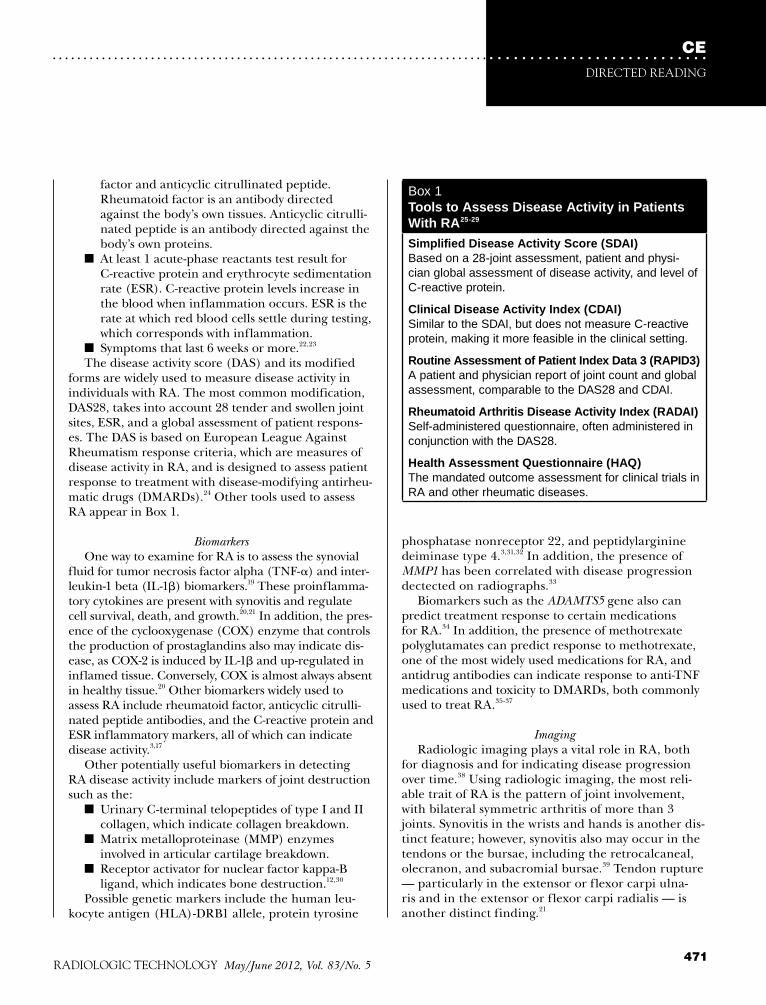
CEDIRECTED READING
. . . . . . . . . . . . . . . . . . . . . . . . . . . . . . . . . . . . . . . . . . . . . . . . . . . . . . . . . . . . . . . . . . . . . . . . . . . . . . . . . . . . . . . . . . . . . . . . . .
471RADIOLOGIC TECHNOLOGY May/June 2012, Vol. 83/No. 5
phosphatase nonreceptor 22, and peptidylarginine deiminase type 4.3,31,32 In addition, the presence of MMP1 has been correlated with disease progression dectected on radiographs.33
Biomarkers such as the ADAMTS5 gene also can predict treatment response to certain medications for RA.34 In addition, the presence of methotrexate polyglutamates can predict response to methotrexate, one of the most widely used medications for RA, and antidrug antibodies can indicate response to anti-TNF medications and toxicity to DMARDs, both commonly used to treat RA.35-37
Imaging Radiologic imaging plays a vital role in RA, both
for diagnosis and for indicating disease progression over time.38 Using radiologic imaging, the most reli-able trait of RA is the pattern of joint involvement, with bilateral symmetric arthritis of more than 3 joints. Synovitis in the wrists and hands is another dis-tinct feature; however, synovitis also may occur in the tendons or the bursae, including the retrocalcaneal, olecranon, and subacromial bursae.39 Tendon rupture — particularly in the extensor or flexor carpi ulna-ris and in the extensor or flexor carpi radialis — is another distinct finding.21
factor and anticyclic citrullinated peptide. Rheumatoid factor is an antibody directed against the body’s own tissues. Anticyclic citrulli-nated peptide is an antibody directed against the body’s own proteins.
n At least 1 acute-phase reactants test result for C-reactive protein and erythrocyte sedimentation rate (ESR). C-reactive protein levels increase in the blood when inflammation occurs. ESR is the rate at which red blood cells settle during testing, which corresponds with inflammation.
n Symptoms that last 6 weeks or more.22,23
The disease activity score (DAS) and its modified forms are widely used to measure disease activity in individuals with RA. The most common modification, DAS28, takes into account 28 tender and swollen joint sites, ESR, and a global assessment of patient respons-es. The DAS is based on European League Against Rheumatism response criteria, which are measures of disease activity in RA, and is designed to assess patient response to treatment with disease-modifying antirheu-matic drugs (DMARDs).24 Other tools used to assess RA appear in Box 1.
Biomarkers One way to examine for RA is to assess the synovial
fluid for tumor necrosis factor alpha (TNF-) and inter-leukin-1 beta (IL-1) biomarkers.19 These proinflamma-tory cytokines are present with synovitis and regulate cell survival, death, and growth.20,21 In addition, the pres-ence of the cyclooxygenase (COX) enzyme that controls the production of prostaglandins also may indicate dis-ease, as COX-2 is induced by IL-1 and up-regulated in inflamed tissue. Conversely, COX is almost always absent in healthy tissue.20 Other biomarkers widely used to assess RA include rheumatoid factor, anticyclic citrulli-nated peptide antibodies, and the C-reactive protein and ESR inflammatory markers, all of which can indicate disease activity.3,17
Other potentially useful biomarkers in detecting RA disease activity include markers of joint destruction such as the:
n Urinary C-terminal telopeptides of type I and II collagen, which indicate collagen breakdown.
n Matrix metalloproteinase (MMP) enzymes involved in articular cartilage breakdown.
n Receptor activator for nuclear factor kappa-B ligand, which indicates bone destruction.12,30
Possible genetic markers include the human leu-kocyte antigen (HLA)-DRB1 allele, protein tyrosine
Box 1 Tools to Assess Disease Activity in Patients With RA25-29
Simplified Disease Activity Score (SDAI) Based on a 28-joint assessment, patient and physi-cian global assessment of disease activity, and level of C-reactive protein.
Clinical Disease Activity Index (CDAI) Similar to the SDAI, but does not measure C-reactive protein, making it more feasible in the clinical setting.
Routine Assessment of Patient Index Data 3 (RAPID3) A patient and physician report of joint count and global assessment, comparable to the DAS28 and CDAI.
Rheumatoid Arthritis Disease Activity Index (RADAI) Self-administered questionnaire, often administered in conjunction with the DAS28.
Health Assessment Questionnaire (HAQ) The mandated outcome assessment for clinical trials in RA and other rheumatic diseases.

CEIMAGING RHEUMATIC DIsEAsEs
472 May/June 2012, Vol. 83/No. 5 RADIOLOGIC TECHNOLOGY
. . . . . . . . . . . . . . . . . . . . . . . . . . . . . . . . . . . . . . . . . . . . . . . . . . . . . . . . . . . . . . . . . . . . . . . . . . . . . . . . . . . . . . . . . . . . . . . . . .
RadiographyJoint damage is one of the most important mea-
sures of disease activity in early RA, and conventional plain film radiography of the hands and feet remains the gold standard for assessing joint damage (see Figure 2). Several radiographic scoring systems for RA exist, including the Steinbrocker and Kellgren methods, which are designed to assess the entire indi-vidual. Other scoring methods used to examine for RA include the Larsen and its variations, the Simple Erosion Narrowing Score, and the Sharp score and its variations — all of which are intended to evaluate indi-vidual joint images.21,40
In 1971, John Sharp, MD, a rheumatologist and researcher developed the Sharp score, the first scoring system for RA. His original version was long considered the gold standard for assessing joint damage for RA but is no longer used. The Sharp-van der Heijde modi-fication is now accepted by the U.S. Food and Drug Administration (FDA) and the European Medicines Agency, and it is used widely in rheumatology.41,42
The Sharp-van der Heijde scoring method requires a tally of the number of erosions in the:
n 10 metacarpophalangeal joints.n 8 proximal interphalangeal joints. n 2 interphalangeal joints of the thumbs.n The first metacarpal bone, radius and ulnar
bones, trapezium and trapezoid, and navicular and lunate bones on the right and left sides of the body.
n 10 metatarsophalangeal joints.n 2 interphalangeal joints of the big toes.43
In addition, joint-space narrowing is evaluated in the 10 metacarpophalangeal and 8 proximal interpha-langeal joints; the following joints on the right and left sides of the body: third, fourth, and fifth carpo-metacarpal, multangular-navicular, capitate-navicular-lunate, and radiocarpal; and the 10 metatarsophalan-geal and 2 interphalangeal joints of the big toes. The maximum number of possible erosions in the hands is 160 and 120 in the feet, and the maximum total score for joint-space narrowing in the hands is 120 and 48 in the feet, for a total possible score of 448.43
Computed TomographyAlthough computed tomography (CT) exposes
patients to radiation, it has certain advantages over other imaging modalities, including the ability to evaluate RA-related lung disease and categorize other pathologic features, such as pulmonary abnormalities
(eg, fibrosis).44,45 In a study by Tanaka et al, CT exami-nations of 63 individuals with RA indicated that 57 had ground-glass opacity and 62 had reticulation. From these findings, 4 major CT patterns were identified:
n Usual interstitial pneumonia (n = 26).n Nonspecific interstitial pneumonia (n = 19).n Bronchitis (n = 11).n Organizing pneumonia (n = 5).45 Moreover, usual interstitial pneumonia and nonspe-
cific interstitial pneumonia CT patterns overlapped, and ground-glass opacity was more extensive in indi-viduals with nonspecific interstitial pneumonia CT pat-tern (P = .028).45
In a study of 21 individuals with RA vs healthy con-trols, the intramodality and intermodality agreements of CT and MR in depicting RA-related erosion in the metacarpophalangeal joints were compared with radi-ography. Concerning erosions, CT detected 77 and MR showed 62, whereas radiography indicated 12. Further, CT showed erosion volume as 26 mm3 and MR imag-ing indicated it as 30 mm3. CT and MR imaging had statistically significant intramodality agreement and
Figure 2. Radiograph of advanced RA of the hand with severe destruction and mutilation of the radiocarpal, intercarpal, carpo-metacarpal, and metacarpophalangeal joints. Intercarpal ankylosis is noted. There is also subluxation and deviation of the fourth and fifth fingers. Sommer OJ, Kladosek A, Weiler V, Czembirek H, Boeck M, Stiskal M. Rheumatoid arthritis: a practical guide to state-of-the-art imaging, image interpretation, and clinical impli-cations. Radiographics. 2005;25(2):381-398.

CEDIRECTED READING
. . . . . . . . . . . . . . . . . . . . . . . . . . . . . . . . . . . . . . . . . . . . . . . . . . . . . . . . . . . . . . . . . . . . . . . . . . . . . . . . . . . . . . . . . . . . . . . . . .
473RADIOLOGIC TECHNOLOGY May/June 2012, Vol. 83/No. 5
intermodality agreement (P < .01 for all) in imaging RA-related erosion volumes overall, supporting CT as a potentially valid measure of RA-related joint destruction, according to the Outcome Measures in Rheumatology (OMERACT) group (see Box 2).47
UltrasonographyAlthough its role in RA is still being defined, ultra-
sound imaging has several benefits in RA diagnosis, especially over clinical examination alone. Moreover, it is similar to MR imaging in its ability to detect joint inflammation. Ultrasound imaging also can identify intra-articular fluid collection, syno-vial thickening and hyperemia, and bone erosion with high sensitivity (see Figure 3). Further, conventional color and power Doppler can show neovascularization and flow changes in synovitis. With ultrasonography, the intensity of the color signal is an indicator of disease activity and a negative prognosticator.47
Ultrasound imaging has been effective in evaluating and diagnosing early RA, according to a study retro-spectively comparing ultrasonography findings with clinical diagnosis. In this study, 427 patients were evaluated for RA with ultrasonography, undifferen-tiated arthritis, and spondyloarthritis;
307 (71.9%) of them showed synovial hypertrophy and 120 (25.5%) had joint effusion. In individuals with RA, synovial hypertrophy and joint effusion were detected more frequently in the second and fifth metatarsopha-langeal joints, whereas individuals with crystalline arthri-tis had more involvement in the first metatarsophalan-geal joint. Overall, results showed that single ultrasound imaging had moderate specificity for detecting RA and power Doppler ultrasonography had high specificity for diagnosing the disease.49
Chinese researchers examined 41 individuals with newly diagnosed RA using high frequency and color Doppler ultrasonography. The study’s goal was to eval-uate sonography’s ability to detect synovitis and intra-articular vascularization in these patients. Overall, 91.6% of knee joints were found to have synovial hyperplasia greater than 2 mm, leading investigators to deem ultrasonography an accurate and objective modality for assessing synovial hyperplasia, as well as in detecting vascular pannus formation and joint effusion in the knee joints.50
Foltz et al compared ultrasonography and MR imag-ing in predicting relapse and radiographic evidence of disease progression in RA patients in remission or with low disease activity, as determined by the DAS44.51 All 85 subjects underwent radiographic and ultrasono-graphic examination. The authors used the Sharp-van der Heijde scoring method to determine the results of posteroanterior radiographs of the subjects’ wrists,
Box 2Biomarker Validation48
To be considered valid, a biomarker must possess certain characteristics. In rheumatology, these char-acteristics are defined in the Outcome Measures in Rheumatology (OMERACT) Filter, a means of validat-ing biomarkers. The OMERACT Filter requires that a biomarker demonstrate:
n Feasibility – A biomarker must be useful and prac-tical to implement (eg, cost-effective and interpre-table).
n Truth – A biomarker must be a true and actual measure of what it is intended to measure. It must have face, content, and construct validity.
n Discrimination – A biomarker must be reliable and sensitive to change, and it must discriminate between situations of interest.
Figure 3. Synovitis of the metacarpophalangeal joint. Longitudinal high-resolution (10.5-MHz) sonogram shows thickened synovial tissue (arrows). Sommer OJ, Kladosek A, Weiler V, Czembirek H, Boeck M, Stiskal M. Rheumatoid arthritis: a practical guide to state-of-the-art imaging, image interpretation, and clinical implications. Radiographics. 2005;25(2):381-398.

CEIMAGING RHEUMATIC DIsEAsEs
474 May/June 2012, Vol. 83/No. 5 RADIOLOGIC TECHNOLOGY
. . . . . . . . . . . . . . . . . . . . . . . . . . . . . . . . . . . . . . . . . . . . . . . . . . . . . . . . . . . . . . . . . . . . . . . . . . . . . . . . . . . . . . . . . . . . . . . . . .
coronal images to define pathologic changes in RA. Multiplanar MR imaging is particularly useful in dis-tinguishing between erosions and pre-erosive changes, and in evaluating pannus (inflammatory synovial tissue found in rheumatoid joints). T1-weighted sequences with and without contrast material should be used, in addition to a T2-weighted sequence and a sequence for cartilage evaluation. Fat saturation techniques also may be useful in combination with T1-weighted contrast-enhanced and T2-weighted sequences in evaluating the pathology of RA (see Figure 4).21
High-resolution MR imaging may have a place in the evaluation of certain RA-related complications,
hands, and feet. They also assessed sonograms of the subjects’ wrists, metacarpophalangeal joints 2, 3, and 5, and metatarsophalangeal joints 2, 3, and 5. Each joint was evaluated in dorsal, ventral, and lateral (when pos-sible) views in grey-scale and power Doppler with a 7.5-MHz to 13-MHz transducer.
The authors also assessed subjects with low-field dedicated MR imaging of the dominant hand, with particular attention to the wrist and metacarpopha-langeal joints 2, 3, 4, and 5. Sequences included 3-D T1-weighted MR imaging in the axial and coronal planes before and after intravenous administration of contrast material and short-tau inversion-recovery (STIR) in the axial and coronal planes. Baseline ultra-sound imaging showed synovitis in 74 subjects (88.1%) using grey-scale and 24 (28.9%) using power Doppler. Baseline MR imaging showed synovitis in 82 subjects (96.5%). At 1 year, 3 subjects relapsed and 9 subjects had radiographic evidence of disease progression. Of these 9 subjects, 4 (5%) had been in remission and 5 (6.2%) had low disease activity at baseline. According to the data, baseline power Doppler synovitis assess-ment was predictive of disease relapse and radiograph-ic evidence of disease progression, whereas MR imag-ing had little or no predictive value.51
Currently, the OMERACT Ultrasound Task Force is developing the global synovitis score, a method of measuring global disease activity in RA.52 In addition, low-intensity pulsed ultrasonography is being investi-gated as a possible treatment modality for RA because of its ability to reduce inflammatory activity in synovitis in vitro. Although low-intensity pulsed ultrasonography has shown promise in cancer treatment and as an accel-erator for healing bone fracture, its use to treat RA requires further investigation.20
Magnetic Resonance ImagingCompared with conventional radiography, CT, and
ultrasonography, MR imaging appears to be the most sensitive modality for detecting erosive disease of the soft tissue, cartilage, and bone at an earlier stage.21,53 Because active synovitis and bone marrow inflammation precede and predict cartilage and bone erosion in RA, MR imaging can be used to identify individuals who are candidates for early and aggressive treatment in order to prevent damage.54,55 However, MR imaging does not appear to be cost effective compared with standard risk stratification in individuals with early RA.56
If MR is indicated and available, axial and sagit-tal imaging should be performed on the basis of
Figure 4. Coronal contrast-enhanced fat-saturated T1-weighted magnetic resonance image showing synovitis of the second and third metacarpophalangeal joints in a 52-year-old woman with long-standing RA. A subcortical cyst (arrow) is shown. This type of lesion is called a pre-erosion or subcortical erosion because it is likely to progress to a clear erosion. Sommer OJ, Kladosek A, Weiler V, Czembirek H, Boeck M, Stiskal M. Rheumatoid arthritis: a practical guide to state-of-the-art imaging, image interpretation, and clinical implications. Radiographics. 2005;25(2):381-398.

CEDIRECTED READING
. . . . . . . . . . . . . . . . . . . . . . . . . . . . . . . . . . . . . . . . . . . . . . . . . . . . . . . . . . . . . . . . . . . . . . . . . . . . . . . . . . . . . . . . . . . . . . . . . .
475RADIOLOGIC TECHNOLOGY May/June 2012, Vol. 83/No. 5
for individuals with RA vs controls and individuals with PSA. Positive results on proteomic analyses were correlated with positive results on anticyclic citrul-linated peptide tests, and several other protein peaks — including the 10 832 peak, possibly indicating myeloid-related protein 8 — were identified for RA.58
TreatmentEarly treatment of RA is paramount to limit pain
and disease progression and to prevent joint damage.17 The least invasive treatments include lifestyle changes (eg, incorporating a healthy diet, quitting smoking) and gentle exercise to maintain muscle strength and joint motion while improving mood.19
To reduce RA-related inflammation, aspirin and nonsteroidal anti-inflammatory drugs (NSAIDs) are often recommended; however, individuals with stomach, cardiovascular, and bleeding issues, as well as the elderly, should be cautioned that NSAIDs may increase these complications. Corticosteroids also may be useful in reducing joint swelling and inflammation; however, side effects may require that duration and dose are limited.17
Originally created as an anticancer medication, methotrexate is safe and effective in low doses in the treatment of RA and other rheumatic diseases, and it is considered first-line therapy for RA in particular.59-61 Evidence also has indicated its efficacy in combination with certain monoclonal antibodies.62
Biologics are medications that suppress the immune system and reduce inflammation.63 In RA, biologics include white blood cell modulators and TNF, IL-6, and COX-2 inhibitors. Biologics can increase risk of bacterial, viral, and fungal infections because of their immunosuppressant qualities, and have been linked with leukemia, lymphoma, and psoriasis.17,64 Additionally, COX-2 inhibitors carry warnings about heart disease and stroke.17
The development of antirheumatic biologic medica-tions was aimed at selectively blocking the effects of pro-inflammatory cytokines, interfering with costimulatory signals, or depleting immune cells involved in the RA dis-ease process. However, not all patients respond to biolog-ics, so research is ongoing to identify biomarkers of treat-ment response, as well as predictors of adverse events.10
Surgical intervention may be necessary in extreme cases of RA or when an individual with RA does not respond to medication. Surgery can range from removal of the joint lining (synovectomy) to total joint replacement or even total ankle, knee, hip, or shoul-der replacement.17,19
such as subclinical atherosclerosis potentially leading to cardiovascular disease, and in the monitoring of cardiovascular effects of antirheumatic medications. Like CT and carotid ultrasonography, which are widely used for imaging the arterial wall, MR imaging may be useful in imaging plaque composition, vessel wall inflammation, and certain myocardial abnormalities. With the black-blood technique, the signal from the flowing blood is suppressed and appears dark or black on imaging to better visualize the adjacent vessel wall. With the bright-blood technique, assessment of fibrous cap thickness and morphological integrity of athero-sclerotic plaque can be made.
Cardiac contrast-enhanced MR imaging can provide information about myocardial perfusion deficits, ven-tricular function, and myocardial viability. Although high-resolution MR imaging has limited ability to image the coronary artery wall because of blood flow, motion, and spatial artifacts, it has sensitivity to flow and excellent soft-tissue contrast.57
MR imaging may be preferred over CT to assess early RA because it can detect soft-tissue changes and bone and cartilage damage. In the assessment of sub-clinical RA, both MR imaging and ultrasonography are considered superior to radiography because of their direct, valid, sensitive, and specific visualiza-tion of inflammatory lesions and structural damage.51 Although ultrasonography and conventional radiogra-phy — the gold standard for assessing joint damage in RA — are more readily available and cost effective than MR imaging, they cannot show the entire spectrum and pathology of the disease.21
Imaging and BiomarkersThe best way to incorporate biomarkers into the
rheumatology clinical setting is being investigated, and this quest includes examining radiologic imaging modalities for their unique abilities to detect biomark-ers.24 Additionally, radiologic imaging itself may be considered a biomarker in the future because it fulfills aspects of the OMERACT criteria (eg, truth, discrimi-nation, and feasibility).41
De Seny et al investigated surface-enhanced laser desorption/ionization time-of-flight mass spectrom-etry (SELDI-TOF-MS) for its usefulness in identifying serum protein biomarkers in RA.58 In this study, 103 serum samples were obtained from individuals with RA and from healthy controls. Using SELDI-TOF-MS, the most discriminative mass/charge values — pos-sibly serving as biomarkers — were shown on arrays

CEIMAGING RHEUMATIC DIsEAsEs
476 May/June 2012, Vol. 83/No. 5 RADIOLOGIC TECHNOLOGY
. . . . . . . . . . . . . . . . . . . . . . . . . . . . . . . . . . . . . . . . . . . . . . . . . . . . . . . . . . . . . . . . . . . . . . . . . . . . . . . . . . . . . . . . . . . . . . . . . .
For osteoarthritis diagnosis, conventional radiogra-phy has been used to show joint-space narrowing, indi-cating cartilage loss. However, it does not show soft tis-sue and articular cartilage adequately and detects only end-stage changes in bone.67,69 Thus, MR has become the preferred imaging modality because of its ability to detect premorphologic changes, such as intrasubstance matrix changes prior to morphologic alterations. However, detection may be limited by cartilage soften-ing.69,70 MR imaging also can be used to image cartilage and other soft tissue and bone.67
Arthroscopic imaging of the articular cartilage is considered the clinical standard for detection and stag-ing of early cartilage injury and degeneration. During arthroscopy, the cartilage is graded on a scale of 0 to 4 using the Outerbridge scoring system:
n 0 = Firm.n 1 = Softening.n 2 = Fissuring less than 50% of cartilage thickness.n 3 = Fissuring greater than 50% of cartilage thick-
ness.n 4 = Exposed bone.69
Optical coherence tomography (OCT), currently used in ophthalmology, also is being investigated for detection of articular cartilage injury and deteriora-tion. OCT is similar to ultrasonography, but it uses infrared light to produce high-resolution (4 μm to 20 μm) digital images. Further study of OCT is need-ed to determine its precise diagnostic usefulness in osteoarthritis.69
TreatmentOral analgesics may be effective in combating
mild to moderate pain resulting from osteoarthritis; however, narcotics may be required if pain is severe. NSAIDs can reduce inflammation in osteoarthritis, but the elderly — who are at increased risk for the disease — should be warned about possible stomach, cardiovas-cular, and bleeding complications.67
Lifestyle adjustments also may be useful in fighting pain, including:
n Resting the joints to avoid overexertion.n Gentle exercise to increase muscle strength
around the joints.n Maintaining a healthy weight to decrease stress
on the weight-bearing joints.n Incorporating assistive devices such as a cane.n Making ergonomic modifications.n Using a hot or cold compress or an over-the-
counter pain cream.67
Prognosis for those with RA is directly dependent on symptom severity. Individuals with rheumatoid factor, anticyclic citrullinated peptide antibody, and subcuta-neous nodules tend to have more severe disease. Those who develop RA at a younger age seem to have more rapid disease progression.17 With the help of biomarker science, researchers are hopeful that RA prognosis will greatly improve.
OsteoarthritisOsteoarthritis is the most common form of arthritis
worldwide. Unlike RA, osteoarthritis is a degenerative disorder — not an autoimmune disorder — that results from excess stress on the cartilage, repeated injury, or aging.3,19,65,66 It is believed that hereditary weakness of the cartilage also may play a role in an individual’s likelihood of developing osteoarthritis.3 Osteoarthritis is also different from RA in that it does not affect the heart or lungs.19 Osteoarthritis most often results in joint pain and disability and is the most common con-dition leading to total knee and hip replacement.65
Osteoarthritis occurs more frequently in women, and risk increases with age. Other risk factors include:
n Bone deformity, malformed joints, or defective cartilage.
n Previous joint injury.n Obesity, sedentary lifestyle, and certain professions
that require repetitive stress on a particular joint.n Certain comorbidities, including diabetes, under-
active thyroid, gout, or Paget disease.67
Diagnosis and ImagingDiagnosis of osteoarthritis is based primarily on
detailed patient history and physical examination. Typically, pain is present in only 1 or a few joints, and joint involvement tends to be symmetrical. With disease progression, duration of morning joint stiffness may be prolonged (longer than 30 minutes) and joint enlarge-ment may be visible.68
Because many of the signs and symptoms of osteoar-thritis are the same as those in other rheumatic diseases, particularly RA and gout, laboratory tests for rheuma-toid factor and ESR may be helpful in diagnosis.67,68 Synovial fluid analysis also may be useful in ruling out other diseases. With osteoarthritis, the white blood cell count is commonly less than 500 cells/mm2 and mostly composed of mononuclear cells, whereas with inflam-matory conditions, the white blood cell count is typically greater than 2000 cells/mm2 and almost entirely com-posed of neutrophils.68

CEDIRECTED READING
. . . . . . . . . . . . . . . . . . . . . . . . . . . . . . . . . . . . . . . . . . . . . . . . . . . . . . . . . . . . . . . . . . . . . . . . . . . . . . . . . . . . . . . . . . . . . . . . . .
477RADIOLOGIC TECHNOLOGY May/June 2012, Vol. 83/No. 5
n Chest radiograph.n Kidney biopsy or kidney function blood tests.n Liver function tests.n Urinalysis.72
The presence of lupus may alter test results for rheu-matoid factor and ESR, both of which are biomark-ers indicated in RA, as well as tests for complement (C3 and C4), antithyroglobulin antibody, antithyroid microsomal antibody, and cryoglobulin. In addition, lupus may affect the results of liver and kidney function blood tests.72
Because of the increased risk of cardiovascular comorbidity with lupus, monitoring of systolic function and pericardial and valvular function is important. Cardiac function can be assessed with echocardiogra-phy or left-ventricle angiography, using either the con-ventional method or technetium-99m myocardial per-fusion gated single-photon emission computed tomog-raphy (SPECT).75,76 Gated SPECT has been shown to provide clear ventricular volumes and ejection frac-tions, even in ischemic or hypoperfused individuals.75
More recently, cardiac MR imaging has replaced angiography because of its sensitivity in detecting changes characteristic of lupus myocarditis. When used for the detection of myocardial inflammation, early and late gadolinium-enhanced T2-weighted cardiac MR imaging have demonstrated sensitivity and specific-ity rates of 76% and 95.5%, respectively. Compared to echocardiography and SPECT, cardiac MR imaging is superior in:
n Assessing left ventricle size, function, and mass.n Providing high-spatial resolution.n Showing low intra- and interobserver variability.n Reproducibility.76
TreatmentWhen in the sun, individuals with lupus should wear
protective clothing, sunglasses, and sunscreen. Because there is no cure for lupus, the treatment goal is manag-ing symptoms with NSAIDs and low-dose corticoste-roids. The antimalarial hydroxychloroquine may be added to a treatment regimen with corticosteroids to manage skin and arthritis symptoms. More severe dis-ease progression may require high-dose corticosteroids to decrease immune response or cytotoxic medications to block cell proliferation; however, these medications are not without side effects, including nausea, anemia, and liver damage.72
Treatment response in lupus is measured using the Systematic Lupus Erythematosus Disease Activity Index
Corticosteroid injections may be administered to relieve joint pain. Hyaluronic acid derivative injec-tions are similar to a component found in joint fluid and may help cushion the bones of the knee. In more severe cases, bone-realignment surgery (osteotomy) of the knee may be necessary to redistribute weight to a nondamaged part of the knee. Joint replacement (arthroplasty) with prostheses is used most often in the hip and knee joints.67
LupusLike Sjögren syndrome, lupus is a chronic auto-
immune rheumatic disease. With lupus, the body’s immune system mistakenly attacks healthy cells, caus-ing damage to the skin, blood vessels, tissues, and organs.71 Like RA, the cause of lupus is unknown. However, certain viruses such as Epstein-Barr may trig-ger disease in individuals with genetic susceptibility. Several medications also have been shown to trigger medication-induced lupus, the most common of which are isoniazid, hydralazine, and procainamide.72,73 Lupus occurs more frequently in women than in men, particu-larly of African American or Asian descent.72
Lupus has many of the same signs and symptoms as RA (eg, joint pain and stiffness, fatigue) with the addi-tion of rash — including the so-called “butterfly rash” across the cheeks — sensitivity to sun, hair loss, and discoloration of the fingers or toes when exposed to cold (Raynaud phenomenon). In advanced cases, lupus can result in damage to the kidneys, anemia or blood clots, chest pain from inflammation of pericardium or pleura, or seizures and strokes.4 Other features inde-pendent of lupus, such as coronary artery or valvular disease, drug-related cardiotoxicity (from cyclophos-phamide and chloroquine), and lupus myocarditis, increase the risk for myocardial dysfunction in indi-viduals with lupus.72
Diagnosis and ImagingTo be diagnosed with lupus, an individual must be
positive for 4 of 11 typical signs of the disease. The 11 typical signs of lupus are malar or discoid rash; photosensitivity; oral ulcers; arthritis; serositis; kidney, neurological, immunologic, or blood disorders; and abnormal antinuclear antibody. A physical examination is required to detect a heart or pleural friction rub, as well as testing for antinuclear antibody, a biomarker found in 97% of individuals with lupus.72,74
Other diagnostic tests include, but are not limited to:n Complete blood count.

CEIMAGING RHEUMATIC DIsEAsEs
478 May/June 2012, Vol. 83/No. 5 RADIOLOGIC TECHNOLOGY
. . . . . . . . . . . . . . . . . . . . . . . . . . . . . . . . . . . . . . . . . . . . . . . . . . . . . . . . . . . . . . . . . . . . . . . . . . . . . . . . . . . . . . . . . . . . . . . . . .
inflammatory arthritis and psoriasis and the absence of serological tests for rheumatoid factor. Even though these criteria remain widely used, researchers have questioned the ability of this method to distinguish between PSA and RA. Other systems of classification have been created, including the Composite Psoriatic Disease Activity Index and the Classification Criteria for Psoriatic Arthritis. The latter is considered a simple and highly specific method to classify PSA. A score of 3 or more of the following 5 points indicates disease:
n Presence or family history of psoriasis. n Psoriatic nail dystrophy.n Negative test result for rheumatoid factor.n Current or past dactylitis.n Radiographic finding of juxta-articular new bone
formation appearing as ill-defined ossification near joint margins in the hands or feet.83,84
Five types of PSA are widely accepted: asymmetrical oligoarthritis, asymmetrical arthritis, symmetrical poly-arthritis, arthritis mutilans, and psoriatic spondylitis.85 However, a study by Marshall et al found only 2 clear-cut PSA categories — axial and peripheral — because the disease evolves over time. Axial disease is defined as the presence of sacroiliitis with or without peripheral arthri-tis; peripheral disease is defined as peripheral arthritis without sacroiliitis. These classifications were devised, in part, to assess the associations with the HLA antigen and PSA. In particular, the HLA-B27 antigen was strong-ly associated with axial disease (43% vs 11% with periph-eral disease; P < .01). Investigators stressed the potential for the HLA biomarker in predicting disease subsets and subsequent outcomes in PSA.86
Testing for the rheumatoid factor antibody may be useful because rheumatoid factor is often present in RA but not in PSA. Similarly, testing for uric acid crys-tals can be used to indicate gout instead of PSA.82
Radiography is the most often used imaging modality to assess and diagnose PSA.85 As with many rheumatic diseases, it can pinpoint changes in the joints that occur as a result of PSA.82 Further, OCT may play a role in evaluating nail disease related to psoriasis and PSA.87
Compared with clinical assessment, ultrasonogra-phy appears to be superior in detecting inflammation, enthesitis (recurring concentration of muscle stress and inflamation at the point where ligaments or tendons enter the bone), and other pathologies in PSA.88 A study of individuals with PSA (n = 15) and RA (n = 5) vs healthy controls (n = 5) compared results of hand and foot examinations using clinical assessment radiography,
(SLEDAI) and other measures. In a study of the long-term use of cyclosporine A in lupus, the SLEDAI and laboratory analysis indicated that low-dose cyclosporine A — combined with other medications or as monotherapy to maintain long-term remission (2 years or more) — is effective and generally well tolerated in patients with moderate or severe lupus who show poor response to cor-ticosteroids or conventional DMARDs. This finding may spare individuals with lupus from more cytoxic drugs.77
Lupus can lead to lupus nephritis, an inflammation of the kidneys, which can cause chronic kidney fail-ure in severe cases.78 Thus, it is imperative to manage the disease with medications such as corticosteroids or immunomodulators to improve kidney function. Dialysis or even kidney transplant may be necessary with progression of lupus.79
Researchers are searching for predictive and prog-nostic biomarkers in lupus nephritis. Ideally, these biomarkers could help rheumatologists predict an individual’s response to particular immunosuppressive therapy and risk for progression to end-stage renal dis-ease. Through molecular evaluation of kidney biopsy, researchers extrapolated 3 biomarkers that relate to pathological indices of kidney injury and function: the EGF, MMP7, and COL1A1 mRNA transcripts.80
Psoriatic ArthritisPSA is a type of arthritis that occurs in approxi-
mately one-quarter of individuals with psoriasis, caus-ing scaling and redness of the skin.3,81 PSA most often affects the joints at the ends of the fingers and toes, and fingernail and toenail changes are characteristic of the condition.3 PSA also can affect other parts of the body, including the spine, which can lead to ankylosing spondylitis. With PSA, flares may be intermittent with periods of remission, and disease can range from mild to severe.82
Like lupus, PSA develops when the immune system mistakenly attacks healthy cells and tissue, possibly because of genetic or environmental factors, or both. The attacks cause inflammation in the joints and over-production of skin cells. Although rare, some individu-als with PSA may develop arthritis mutilans, a severe form of arthritis that destroys the small bones of the hands, causing pain, deformity, and disability.82
Diagnosis and ImagingThe Moll and Wright criteria provide a system of
classification and diagnosis for PSA. Using these cri-teria, PSA can be diagnosed based on the presence of

CEDIRECTED READING
. . . . . . . . . . . . . . . . . . . . . . . . . . . . . . . . . . . . . . . . . . . . . . . . . . . . . . . . . . . . . . . . . . . . . . . . . . . . . . . . . . . . . . . . . . . . . . . . . .
479RADIOLOGIC TECHNOLOGY May/June 2012, Vol. 83/No. 5
TreatmentPSA is not curable and, as with other rheumatic
diseases, treatment is aimed at controlling symptoms and preventing damage to the joints. Cold compresses can be applied to the joints to numb pain, and heat-ing pads may be useful to relax the muscles and ten-dons. Medications for PSA include those used for RA: NSAIDs, DMARDs, immunosuppressants, and anti-TNFs. Further, it is important to protect the joints by avoiding strain and maintaining a healthy weight.82
Ankylosing SpondylitisAS is a type of inflammatory rheumatic disease
characterized by involvement of the sacroiliac joints at the base of the spine where the spine attaches to the pelvis. When the disease progresses and inflammation persists, new bone is formed as the body attempts to repair itself. Eventually, this newly formed bone gradu-ally spans the space between the vertebrae, and sections of the vertebrae fuse together, resulting in a stiff and inflexible spine.95 In severe cases, an individual may develop a curved or stooped posture.95,96 Fusion of the bones in the rib cage also can occur, thereby restricting lung capacity and function.95
Onset of AS is gradual and commonly presents as lower back or hip pain. One of the most common symptoms of AS is inflammation of the eye (uveitis), rapidly leading to eye pain, sensitivity to light, and blurred vision.95 AS also may be accompanied by fever, fatigue, loss of appetite, eye inflammation, and in rare cases, lung or heart complications. AS is more com-mon in men, most often between the ages of 20 and 30 years, and occurs more frequently in individuals of Native American descent.96
Diagnosis and ImagingLike many rheumatic diseases, the cause of AS is not
known. However, there appears to be a strong genetic link, as the majority of individuals with AS test positive for the HLA-B27 gene and certain interleukins (IL-1 and IL-23R), which are considered biomarkers of the disease.95,97
In addition to testing for these biomarkers, diag-nostic assessments for AS may include radiographs of the back and pelvis, chest measurements, and other laboratory tests to assess inflammation.95,96 In addition to diagnostic assessment, radiographs can be used to detect characteristic changes in the joints and bones, although such effects may not be visible in early AS (see Figure 5).95
ultrasonography, and contrast-enhanced MR imaging. Both ultrasonography and MR imaging were more sensi-tive to inflammation and destruction than either clinical assessment or radiography. Ultrasonography detected more joint and bone changes in individuals with PSA vs those with RA. High intraobserver agreement was found for all destructive changes (85% to 100%) and for inflammatory pathologies (73% to 100%) using ultraso-nography and MR imaging. Researchers concluded that both ultrasonography and MR imaging have the poten-tial to improve detection of joint and tendon inflamma-tion and destruction as well as entheses in the hands and feet of individuals with PSA.89
MR imaging has improved diagnosis of PSA, in addition to psoriatic spondyloarthropathy and inflam-mation of the entheses (the point where tendons or ligaments insert into bone).90 MR imaging is useful in assessing the tendons and ligaments in the feet and back, commonly implicated in PSA.82 The OMERACT Psoriatic Arthritis Magnetic Resonance Imaging Score is a system for scoring PSA using MR imaging of the hands, including recommendations for most appropri-ate MR imaging sequences.91 It has shown reliability and sensitivity to change in clinical trials, suggesting that it may be a valuable means of monitoring change in inflammation during PSA disease activity.92
MR imaging may help distinguish PSA from RA. According to a study by Schwenzer et al, a statistically significant difference (P < .01) between the 2 diseases was found in synovial enhancement 15 minutes after contrast injection. The authors used 3-T whole-body MR imaging and a 3-D encoded spoiled gradient-echo sequence for the measurement of the contrast-medium uptake time in the synovial tissue. Relative enhance-ment rates were not significant at other time points investigated (35 seconds, 52 seconds, and 3 minutes), whereas correlations were seen in inflammatory and dynamic contrast-enhanced parameters in individuals with RA but not in those with PSA. In short, the differ-ence shown in synovial tissue enhancement 15 minutes after contrast injection may be important in distin-guishing PSA from RA.93
Similarly, high-resolution dynamic contrast-enhanced MR imaging also may be useful in distinguishing PSA from osteoarthritis. Researchers examined the rates of synovial contrast uptake in MR images of the hands of 26 individuals. Statistically significant (P = .0275) enhancement again was seen 15 minutes after contrast injection, leading the researchers to conclude that late enhancement is essential for guiding therapy.94

CEIMAGING RHEUMATIC DIsEAsEs
480 May/June 2012, Vol. 83/No. 5 RADIOLOGIC TECHNOLOGY
. . . . . . . . . . . . . . . . . . . . . . . . . . . . . . . . . . . . . . . . . . . . . . . . . . . . . . . . . . . . . . . . . . . . . . . . . . . . . . . . . . . . . . . . . . . . . . . . . .
Doppler ultrasonography allows for the detection of struc-tural and inflammatory abnormalities of the enthesis, even when radiographs are normal, making it a comple-ment to physical examination in the diagnosis of AS.99
OMERACT also maintains criteria for MR imaging in AS, created in association with the SpondyloArthritis international Society. The criteria include imaging of structural lesions in the sacroiliac joints, which is essential for the diagnosis of sacroiliitis in patients with AS and spodyloarthritis.100 These criteria challenge the former standard of diagnosing AS using conventional radiography, stating instead the benefits of MR imag-ing and ultrasonography, which include the ability to diagnose AS early in the absence of radiographic evi-dence of sacroiliitis.101
MR imaging is useful for the quantification of inflammatory and structural lesions, and to assess dis-ease activity.102 Furthermore, MR imaging is indicated when arthritis of the spine is suspected.21
TreatmentLike most rheumatic conditions, there is no cure
for AS, so treatment focuses on reducing discomfort, managing pain and stiffness, preventing damage and deformity, and, if possible, improving function. Physical therapy and proper exercise (eg, deep breathing to keep the rib cage flexible and swimming) play an important role in the treatment of AS. Because of the potential for rib cage involvement, individuals with AS are advised not to smoke.96
It is recommended that individuals with AS sleep on a firm mattress to keep the spine straight and use chairs and other furniture designed to maintain proper spinal integrity.96 Maintaining upright pos-ture is important because, if the spine vertebrae fuse, daily function will most likely be easier if the spine fuses straight instead of curved forward.95 In addition, because AS can cause the spine to become rigid, care should be taken to avoid sudden impact.96
The most common medications for AS are aspirin and NSAIDs, as well as DMARDs such as methotrex-ate for more severe cases.96 Anti-TNF medication may be useful to block the TNF protein that causes inflammation in both PSA and RA.95,103 Duloxetine, a serotonin-norepinephrine reuptake inhibitor and an antidepressant medication, has been approved by the FDA for the treatment of chronic back pain, a com-mon result of AS.
When medication is not enough, AS may require surgery to help relieve severe pain or repair joint
CT and MR imaging may be used for enhanced imag-ing, including cross-sectional imaging of internal struc-tures and better visualization of soft tissue, respectively, as radiography often underestimates AS-related sacroili-itis.95,98 Compared with radiography, ultrasonography has high sensitivity but low specificity in detecting erosion, swelling, and AS-related new bone formation. Power
Figure 5. Radiograph of the lateral lumbar spine show-ing ankylosing spondylitis. Public domain image from Wikimedia/Creative Commons.

CEDIRECTED READING
. . . . . . . . . . . . . . . . . . . . . . . . . . . . . . . . . . . . . . . . . . . . . . . . . . . . . . . . . . . . . . . . . . . . . . . . . . . . . . . . . . . . . . . . . . . . . . . . . .
481RADIOLOGIC TECHNOLOGY May/June 2012, Vol. 83/No. 5
Diagnosis and ImagingThe standard for diagnosing gout is to determine
whether tophi are present in aspirated joint fluid; how-ever, when joint fluid samples are not obtained, disease manifestation, serum urate levels, and radiologic findings are needed to establish diagnosis. Furthermore, diagno-sis can be complicated, for example, in individuals with unusual presentation, gout attack with normal serum urate levels, or hyperuricemia with an inflammatory dis-ease that mimics gout (eg, septic arthritis, osteomyelitis, pseudogout with calcium deposition, and RA).108
Testing for gout requires looking for uric acid — the main marker of the disease — using synovial fluid analysis, synovial biopsy, urinalysis, or blood screening. However, high uric acid levels do not indicate gout in all individuals. The true marker of the disease is the crystallization of the uric acid.106
Biomarkers associated with gout have been identified as the URAT1 and SLC2A9 renal urate transporters.105 In addition, the HLA-B*5801 allele is associated with allopurinol hypersensitivity, and
damage.96 Hip replacement also may be necessary if the hip becomes severely damaged.95
GoutOnce called the “rich man’s disease,” gout has been
linked with overindulgence historically available only to the affluent. Prominent figures with gout have included Alexander the Great, Charlemagne, and Charles Darwin.104 Today, gout affects people of every socioeco-nomic status. In fact, its prevalence has increased in recent decades, and approximately 2.1 million people in the United States suffer from gout.3,105 Gout occurs most frequently in men, but its prevalence in women increases after menopause.106,107
Although the exact cause of gout is unknown, it is linked to heredity, alcohol consumption, and medica-tions that disrupt the removal of uric acid from the body, including hydrochlorothiazide and certain diuret-ics. In addition, gout is more common in individuals with diabetes, kidney disease or impaired function, obe-sity or metabolic syndrome, sickle cell or other anemias, and leukemia and other cancers of the blood.105,106
Gout, or gouty arthritis, results when uric acid builds up in the synovial fluid and hardens in the joints, creating needle-like crystallizations. Uric acid results from the normal breakdown of purines, a natu-rally occurring substance found in the body’s cells and in food.3 Buildup can result when the body overpro-duces or is unable to properly dispel uric acid.106 The hardened crystals create inflammation, swelling, and pain in the affected joint, most often in the big toe, knee, or ankle.3,106
Gout can be acute or chronic. Acute gout usually affects just 1 joint. Chronic gout may involve more than 1 joint repeatedly and may lead to joint damage and immobility. With chronic gout, damage to the joints can occur and uric acid crystals (tophi) may form under the skin; however, tophi usually develop after many years.3
With gout, onset of pain can be sudden, often occurs at night, and may be described as throbbing, crushing, or even excruciating. The affected joint may be warm and red, and so tender that even placing something as light as a bed sheet over the skin may cause pain.3
Dietary risk factors for gout include high consump-tion of red meat, fructose, and alcohol, particularly beer. Conversely, high consumption of coffee, low-fat dairy products, and vitamin C are associated with lower risk of gout.105
Figure 6. Radiograph of left foot showing gout in the big toe. Soft issue swelling at the lateral border of the foot also is shown. Public domain image from Wikimedia/Creative Commons.

CEIMAGING RHEUMATIC DIsEAsEs
482 May/June 2012, Vol. 83/No. 5 RADIOLOGIC TECHNOLOGY
. . . . . . . . . . . . . . . . . . . . . . . . . . . . . . . . . . . . . . . . . . . . . . . . . . . . . . . . . . . . . . . . . . . . . . . . . . . . . . . . . . . . . . . . . . . . . . . . . .
show synovial and soft tissue inflammation and can be used to assess the composition and vascularity of tophi.114 In fact, ultrasonography can detect tophi on cartilage. It is also useful in assessing small joint effusion and in guiding joint aspiration to evaluate the volume of tophi.111
The typical appearance of gout on a sonogram includes a double-contour sign consisting of the hyper-echoic bony contour and a parallel hyperechoic line of tophi on hyperechoic or anechoic hyaline cartilage. Tophi often look like wet clumps of sugar and may be surrounded by an anechoic halo.115
Although the most expensive and therefore the least feasible modality, according to the OMERACT filter, MR imaging is useful in assessing inflammation in gout and other crystalline disorders.55 MR imaging is able to detect synovial involvement in early phase disease, but it lacks specificity and requires long examination time.112 However, MR imaging is the only modality that can visualize bone marrow edema associated with erosions, which may be helpful in characterizing and distinguishing tophi from other soft tissue nodules.111 This important distinction can lead to early diagnosis and treatment, which can prevent future damage to the cartilage and joints.55
TreatmentManaging flare-ups is the treatment goal for individ-
uals with gout, who can stave off attacks and long-term damage through diet and lifestyle changes. In particu-lar, they are advised to avoid:
n Alcohol.n Purine-rich foods, including anchovies, organ
meat, legumes, mushrooms, and spinach.n Certain types of yeast, including baker’s and
brewer’s yeast.n Fried and fatty foods, including ice cream and
salad dressing.106
Additionally, individuals with gout should be informed about the danger of losing too much weight too quickly, which can lead to the development of uric acid kidney stones.106
Complementary and alternative medicine studies have found that coffee, vitamin C, and cherries are associated with decreased levels of uric acid in the body, which may help prevent the onset of gout; however, these treatments are not always as rigorously evaluated as clinical trials and may not be approved by the FDA.107
The American Diabetes Association recommends the following to help prevent a gout attack:
allopurinol is among the most common treatments for the disease.109,110
Radiography is the primary imaging modality for diagnosing and assessing gout (see Figure 6).111 Although radiography can be used to image alteration of bone, this occurs only after years of active disease, and only about 45% of individuals have radiographic findings.
Dual-energy CT scan appears to be particularly effective in identifying intra-articular and periarticular uric acid crystals in individuals suspected of having gout. Glazebrook et al evaluated dual-energy CT in determining the composition of uric acid kidney stones and in identifying gout-related tophi in the joints and periarticular structures. In this study, 94 subjects underwent dual-energy CT to determine the pres-ence of tophi, with joint aspiration to confirm results. Sensitivity was 100%, specificity was between 79% and 89%, and overall accuracy was 87% to 94%. Although the authors admitted the need for additional studies to confirm results, they postulated other possible uses for dual-energy CT in addition to diagnosis, such as moni-toring disease activity and response to treatment.112
Dalbeth et al developed a preliminary method of assessing bone erosion in gout using conventional CT, with radiographs as a comparator.113 The authors based their method on the Sharp-van der Heijde method for RA, but incorporated imaging of more sites typically affected by gout. In summary, CT scans and modified assessment methods were:
n More feasible and effective than plain radio-graphs in quantifying bone erosion.
n Had high interobserver reliability.n Correlated well with other measures of gout
severity. Despite their findings, however, the researchers stressed
that additional testing of this method is necessary.113 In cases where diagnosis of gout is not straightforward
(ie, complicated by normal serum urate levels), dual-energy CT (80 kVp and 140 kVp) may be useful in differ-entiating urate crystals from calcium. The ability to dif-ferentiate tophi from calcium deposits makes dual-energy CT superior to radiography and routine diagnostic CT, which show mineralizations as indistinguishable high attenuations. Dual-energy CT also has the advantage of eliminating misregistration artifacts and reducing errors due to patient movement, and allows for 360° modeling of urate crystal deposits.108
Ultrasonography can be useful in imaging the inflammatory nature of gout. Like MR imaging, it can

CEDIRECTED READING
. . . . . . . . . . . . . . . . . . . . . . . . . . . . . . . . . . . . . . . . . . . . . . . . . . . . . . . . . . . . . . . . . . . . . . . . . . . . . . . . . . . . . . . . . . . . . . . . . .
483RADIOLOGIC TECHNOLOGY May/June 2012, Vol. 83/No. 5
eye and dry mouth.118 Sjögren syndrome can cause severe neuropathic pain, with small-fiber neuropathy. This creates a burning sensation that can disproportionately affect the torso, extremities, or the face.119 Other com-mon symptoms include swelling, numbness, and debilitat-ing fatigue.118 Although Sjögren syndrome can develop at any time, it is most common after 40 years of age and occurs more frequently in women.120
There appears to be a genetic component that pre-disposes an individual to develop the disease, but it also appears that a trigger such as an infection with a particular virus or bacteria strain is necessary to bring about its onset. The disease is hard to classify because the signs and symptoms vary between individuals but are similar to those of other rheumatic diseases.120
B cell lymphoma (malignant non-Hodgkin lympho-ma) is a potentially life-threatening complication that occurs in approximately 5% of individuals with Sjögren syndrome. This type of lymphoma is most often found in the mucosa-associated lymphoid tissue in the sali-vary glands.121,122
Emerging evidence suggests that abnormalities in memory B cells may be involved in the pathogenesis of primary Sjögren syndrome and its malignant complica-tion of B cell lymphoma. Circulating peripheral blood memory B cells may act on differentiation, activation, selection, and recirculation of B cells from lymphatic tissue and organs. When these processes are interrupt-ed, B cell homeostasis may be disturbed and possibly result in primary Sjögren syndrome.122
Diagnosis and ImagingBlood tests are common in diagnosing and checking
for inflammation, glucose levels, antibodies, and other biomarkers of the disease. The HLA-DR52 antigen is estimated to be present in 87% of individuals with Sjögren syndrome, and other HLA antigens occur with lesser frequency.123 Emerging evidence suggests that the immunoglobulin A anti-c2M3RP antibodies may be diagnostic markers for Sjögren syndrome.124 In addi-tion, the SSA and SSB antibodies also are associated with the disease.123
The American-European classification system for Sjögren syndrome requires an individual to have 4 of the 6 following criteria:
n Dry eyes for more than 3 months.n Dry mouth, swollen salivary glands, and difficulty
swallowing.n Positive Schirmer test to assess the amount of
tear production.
n Drinking 8 to 16 cups of fluid each day, half of which should be water.
n Avoiding alcohol.n Eating a moderate amount of low-fat protein.n Limiting daily intake of meat, fish, and poultry to
4 oz to 6 oz.107
As with most rheumatic diseases, early diagnosis and management of gout is paramount in preventing complications and disability. In addition to physical impairment, the presence of hyperuricemia with gout increases the risk of developing cardiovascular and renal disease.112 Although safe and effective medica-tions for gout are widely known, gout has one of the lowest rates of adherence to therapy.116
Medication should be taken immediately upon experiencing a flare-up of gout, as this is the fastest and most effective way of treating the symptoms of the disease.106,107 For less severe attacks, NSAIDs can help reduce inflammation and pain. More severe attacks may require codeine, hydrocodone, or oxycodone to combat pain, or colchicine to reduce swelling and inflammation. Individuals with severe, chronic gout may require a daily dose of allopurinol or probenecid to decrease uric acid levels in the blood, particularly if they have joint damage, tophi, uric acid kidney stones, or several severe attacks annually.106
In cases of severe gout, joint replacements (includ-ing total ankle replacements) may be necessary to restore function. A study by Barg et al demonstrated that total ankle replacement can produce good func-tional results and carries a low risk of intraoperative and postoperative complications.117
Sjögren SyndromeNamed after the ophthalmologist Henrik Sjögren
(1899-1986) who first described it, Sjögren syndrome can occur alone or in conjunction with other autoim-mune diseases, such as RA or lupus. Sjögren syndrome is a type of rheumatic disease that is believed to result from a viral or bacterial infection. In certain people, white blood cells stimulated from an infection do not die as they normally would after fighting off the infec-tion. Instead, the cells continue to attack the body’s moisture-producing glands. This attack degrades the glands’ function, causes inflammation, and can lead to Sjögren’s hallmark symptoms: joint pain, swelling, numbness, fatigue, dry eyes (keratoconjunctivitis sicca), and dry mouth (xerostomia).118
Because Sjögren syndrome causes the body to attack its own moisture-producing glands, it is linked with dry

CEIMAGING RHEUMATIC DIsEAsEs
484 May/June 2012, Vol. 83/No. 5 RADIOLOGIC TECHNOLOGY
. . . . . . . . . . . . . . . . . . . . . . . . . . . . . . . . . . . . . . . . . . . . . . . . . . . . . . . . . . . . . . . . . . . . . . . . . . . . . . . . . . . . . . . . . . . . . . . . . .
antifungals can be used to treat resulting yeast infec-tions.120 Botulinum toxin injection has shown promise as a novel treatment for recurrent cystic inflamma-tion of the parotid gland, a condition associated with Sjögren syndrome.130 For system-wide symptoms, the antimalarial drug hydroxychloroquine may be effec-tive, as well as the immunomodulators methotrexate and cyclosporine. Punctal occlusion, a minor surgical procedure to seal the tear ducts that drain the tears from the eyes, may be indicated to relieve dry eye.120
Targeted anti-CD20 antibody therapy has shown ben-eficial effects in primary Sjögren syndrome, with or with-out associated B cell lymphoma.121,122 Recent studies of B cell disturbances in Sjögren syndrome have emphasized the role of memory B cell subsets in the pathogenesis of the disease, as well as its malignant complication of B cell lymphoma. This information suggests that B cells may be future targets for treatment of Sjögren syndrome.122
ConclusionWith approximately 46 million Americans living
with arthritis or other rheumatic diseases, rheumatolo-gists and researchers are striving to combat this grow-ing problem, in part, with biomarker science.3 In radi-ology, imaging biomarkers are not only an important part of patient treatment but also are poised to become a vital part of the clinical trial process.15
Joint damage indicated on radiography is one of the most important measures for assessment of early RA, and conventional plain film radiography of the hands and feet using the Sharp-van der Heijde method remains the gold standard for assessing joint damage.38,43 Radiography is also the primary imaging modality for diagnosing and assessing gout; however, in cases where diagnosis of gout is not straightforward, dual-energy CT may be useful in differentiating urate crystals from calcium.108,111 Radiography is most often used to assess and diagnose PSA, with OCT potentially playing a role in evaluating nail disease related to both psoriasis and PSA.85,87
With osteoarthritis, conventional radiography has been used for diagnosis to show joint-space narrowing, indicating cartilage loss; however, only end-stage chang-es in bone are detectable.67,69 Thus, MR imaging has become the radiologic choice for assessment of osteoar-thritis because it can detect premorphologic changes.70 Similarly, cardiac MR imaging has replaced angiography for assessment of lupus because of its sensitivity in detect-ing changes characteristic of lupus myocarditis.76
Examination for AS may involve CT and MR imag-ing for enhanced visualization of internal structures
n Positive minor salivary gland biopsy.n Presence of anti-SSA. n Presence of anti-SSB antibodies.123
Other ocular tests include the slit-lamp test to exam-ine the cornea and ocular surface. Biopsy of tissue in the salivary glands in the lip can detect the presence of inflammatory cells. A spit test measures the total amount of saliva collected to determine severity of dry mouth. A urine sample may be needed to test for kidney damage resulting from complications with Sjögren syndrome.120
Diagnostic imaging may include sialography, salivary scintigraphy, or chest radiography. Sialography is a radiographic examination of the salivary glands. During the procedure, contrast media is injected into the parot-id glands behind the jaw and in front of the ears, allow-ing visualization of the amount of saliva flowing into the mouth. Salivary scintigraphy measures salivary gland function by tracking injected radioactive isotopes. Chest radiography may be useful to show lung inflammation, which can occur with Sjögren syndrome.120 MR imaging, particularly T2 weighted, of the salivary glands also may play a role in diagnosis.125
Ultrasonography is also a valuable diagnostic imag-ing modality in Sjögren syndrome, with higher specific-ity and accuracy than sialography or histopathology.126 Incorporating vascular information from images of the parotid gland parenchyma has been shown to enhance diagnostic capabilities of ultrasonography.127 Moreover, ultrasonography is able to detect nodal changes in the submandibular glands, which may help distinguish Sjögren syndrome from Mikulicz disease.128 In combi-nation with MR imaging, intraductally applied contrast-enhanced ultrasonography may be used to evaluate orbital diseases and secretory dysfunction, conditions associated with Sjögren syndrome.129
TreatmentFor mild symptoms, over-the-counter treatments
such as eye drops and moisture-promoting mouthwash may improve symptoms of dry eye and dry mouth. Basic self-care can limit the effects of Sjögren syn-drome. Oral hygiene, for example, can prevent cavities and tooth loss resulting from dry mouth. Drinking water more frequently also may help.120
With more severe disease, medication and surgery may be indicated. Medications like pilocarpine and cev-imeline can increase saliva production and, occasion-ally, tear production. However, these medications also may increase sweating, abdominal pain, flushing, and urination. NSAIDs can help reduce inflammation, and

CEDIRECTED READING
. . . . . . . . . . . . . . . . . . . . . . . . . . . . . . . . . . . . . . . . . . . . . . . . . . . . . . . . . . . . . . . . . . . . . . . . . . . . . . . . . . . . . . . . . . . . . . . . . .
485RADIOLOGIC TECHNOLOGY May/June 2012, Vol. 83/No. 5
11. Breastcancer.org. What to do if your genetic test results are positive. www.breastcancer.org/symptoms/testing /genetic/pos_results.jsp. Updated March 24, 2009. Accessed December 12, 2011.
12. Machold KP, Nell V, Stamm T, Aletaha D, Smolen JS. Early rheumatoid arthritis. Curr Opin Rheumatol. 2006;18(3):282-288.
13. Konnopka A, Conrad K, Baerwald C, König HH. Cost effectiveness of the determination of autoantibod-ies against cyclic citrullinated peptide in the early diagnosis of rheumatoid arthritis. Ann Rheum Dis. 2008;67(10):1399-1405.
14. Pfeiffer A, Thompson JM, Nelson A, et al. Effects of a 1.5-day multidisciplinary outpatient program for fibromyalgia: a pilot study. Am J Phys Med Rehabil. 2003;82(3):186-191.
15. Smith JJ, Sorenson G, Thrall JH. Biomarkers in imaging: realizing radiology’s future. Radiology. 2003;227(3):633-638.
16. Centers for Disease Control and Prevention. Arthritis. www.cdc.gov/chronicdisease/resources/publications /AAG/arthritis.htm. Updated February 18, 2011. Accessed December 12, 2011.
17. PubMed Health. Rheumatoid arthritis. www.ncbi .nlm.nih.gov/pubmedhealth/PMH0001467/. Accessed December 12, 2011.
18. Bondeson J. The mechanisms of action of disease-modifying antirheumatic drugs: a review with emphasis on macrophage signal transduction and the induc-tion of proinflammatory cytokines. Gen Pharmacol. 1997;29(2):127-150.
19. Torpy JM. Rheumatoid arthritis. JAMA. 2011;305(17):1824.20. Nakamura T, Fujihara S, Yamamoto-Nagata K, Katsura T,
Inubushi T, Tanaka E. Low-intensity pulsed ultrasound reduces the inflammatory activity of synovitis. Ann Biomed Eng. 2011;39(12):2964-2971.
21. Sommer OJ, Kladosek A, Weiler V, Czembirek H, Boeck M, Stiskal M. Rheumatoid arthritis: a practical guide to state-of-the-art imaging, image interpretation, and clini-cal implications. Radiographics. 2005;25(2):381-398.
22. Funovits J, Aletaha D, Bykerk V, et al. The 2010 American College of Rheumatology/European League Against Rheumatism classification criteria for rheumatoid arthritis: methodological report phase I. Ann Rheum Dis. 2010;69(9):1589-1595.
23. Panayi G. Laboratory tests used in the diagnosis and monitoring of rheumatoid arthritis. www.nras.org.uk /about_rheumatoid_arthritis/what_is_ra/how_is_it _diagnosed/laboratory_tests_used_in_the_diagnosis _and_monitoring_of_rheumatoid_arthritis.aspx. National Rheumatoid Arthritis Society website. Reviewed November 21, 2011. Accessed December 12, 2011.
24. Fransen J, van Riel PL. The Disease Activity Score and the EULAR response criteria. Rheum Dis Clin North Am. 2009;35(4):745-757.
and soft tissue, respectively, because AS-related sacroili-itis is often underestimated on radiography.95,98 Finally, diagnostic imaging for Sjögren syndrome may include sialography, salivary scintigraphy, or chest radiography for lung inflammation.120
Venus Williams’ Sjögren syndrome diagnosis gave a face to the somewhat elusive rheumatic diseases. Given that the number of individuals with rheumatic diseases is estimated to reach 60 million by 2020,3 it is impera-tive that those working in radiology take notes from colleagues in oncology and continue to strive for ways to further personalize treatment.
References1. Khan A. Venus Williams and Sjögren’s syndrome: the
autoimmune disorder explained. Los Angeles Times. http://articles.latimes.com/2011/aug/31/news/la-heb -venus-williams-and-sjogrens-syndrome-can-autoimmune -disease-be-fixed-20110831. Published August 31, 2011. Accessed December 12, 2011.
2. Venus Williams: What is Sjögren’s syndrome? ABC News. http://abcnews.go.com/Health/w_MindBodyNews /venus-williams-sjogrens-syndrome/story?id=14426884# .TuT1f2PNltN. Published September 1, 2011. Accessed December 12, 2011.
3. National Institute of Arthritis and Musculoskeletal and Skin Diseases. Arthritis. www.niams.nih.gov/Health _Info/Arthritis/arthritis_rheumatic_qa.asp. Published July 2011. Accessed December 12, 2011.
4. An overview of rheumatic diseases. WebMD website. www.webmd.com/rheumatoid-arthritis/an-overview-of -rheumatic-diseases. Accessed December 12, 2011.
5. Verwij CL, Vosslamber S. New insight in the mechanism of action of rituximab: the interferon signature towards personalized medicine. Discov Med. 2011;12(64):229-236.
6. Miossec P, Verweij CL, Klareskog L, et al. Biomarkers and personalised medicine in rheumatoid arthritis: a proposal for interactions between academia, industry and regulatory bodies. Ann Rheum Dis. 2011;70(10):1713-1718.
7. Biomarkers Definitions Working Group. Biomarkers and surrogate endpoints: preferred definitions and concep-tual framework. Clin Pharmacol Ther. 2001;69(3):89-95.
8. Emery P, Dorner T. Optimising treatment in rheuma-toid arthritis: a review of potential biological markers of response. Ann Rheum Dis. 2011;70(12):2063-2070.
9. Edelbauer M, Ho J. Molecular evaluation of renal biop-sies: a search for predictive and prognostic markers in lupus nephritis. Expert Rev Mol Diagn. 2011;11(6):561-565.
10. Tak PP. A personalized medicine approach to biological treat-ment of rheumatoid arthritis: a preliminary treatment algo-rithm [published online ahead of print September 22, 2011]. Rheumatology (Oxford). doi: 10.1093/rheumatology/ker300.

CEIMAGING RHEUMATIC DIsEAsEs
486 May/June 2012, Vol. 83/No. 5 RADIOLOGIC TECHNOLOGY
. . . . . . . . . . . . . . . . . . . . . . . . . . . . . . . . . . . . . . . . . . . . . . . . . . . . . . . . . . . . . . . . . . . . . . . . . . . . . . . . . . . . . . . . . . . . . . . . . .
adalimumab determines the outcome of switching to etanercept. Ann Rheum Dis. 2011;70(2):284-288.
38. Salaffi F, Carotti M, Ciapetti A, Gasparini S, Filippucci E, Grassi W. Relationship between time-integrated dis-ease activity estimated by DAS28-CRP and radiographic progression of anatomical damage in patients with early rheumatoid arthritis. BMC Musculoskelet Disord. 2011;30(12):120.
39. Temprano K. Rheumatoid arthritis. http://emedicine .medscape.com/article/331715-overview. Accessed December 12, 2011.
40. Strand V, Kingbury SR, Woodworth T, et al. OMERACT 10 sharp symposium: important findings in examination of imaging methods for measurement of joint damage in rheumatoid arthritis. J Rheumatol. 2011;38(9):2009-2013.
41. Dalbeth N, Doyle A, Boyer L, et al. Development of a computed tomography method of scoring bone erosion in patients with gout: validation and clinical implications. Rheumatology (Oxford). 2011;50(2):410-416.
42. Boini S, Guillemin F. Radiographic scoring methods as outcome measures in rheumatoid arthritis: properties and advantages. Ann Rheum Dis. 2001;60(9):817-827.
43. van der Heijde D, Dankert T, Nieman F, Rau R, Boers M. Reliability and sensitivity to change of a simplifica-tion of the Sharp/van der Heijde radiological assess-ment in rheumatoid arthritis. Rheumatology (Oxford). 1999;38(10):941-947.
44. Fewins HE, McGowan I, Whitehouse GH, Williams J, Mallya R. High definition computed tomography in rheumatoid arthritis associated pulmonary disease. Br J Rheumatol. 1991;30(3):214-216.
45. Tanaka N, Kim JS, Newell JD, et al. Rheumatoid arthritis-related lung disease: CT findings. Radiology. 2004;232(1):81-91.
46. Døhn UM, Ejbjerg BJ, Hasselquist M, et al. Rheumatoid arthritis bone erosion volumes on CT and MRI: reliabil-ity and correlations with erosion scores on CT, MRI and radiography. Ann Rheum Dis. 2007;66(10):1388-1392.
47. Rednic N, Tamas MM, Rednic S. Contrast-enhanced ultrasonography in inflammatory arthritis. Med Ultrason. 2011;13(3):220-227.
48. Boers M, Brooks P, Strand CV, Tugwell P. The OMERACT filter for Outcome Measures in Rheumatology. J Rheumatol. 1998;25(2):198-199.
49. Scire CA, Iagnocco A, Meenagh G. Ultrasound imaging for the rheumatologist XXXIII. Sonographic assessment of the foot in early arthritis patients. Clin Exp Rheumatol. 2011;29(3):465-469.
50. Ren JH, Guo FJ, Han XJ, Chen XH, Ma N, Jiang WL. Assessment of synovitis in the knee of patients with newly-diagnosed rheumatoid arthritis using high fre-quency and color Doppler ultrasonography [in Chinese]. Zhonghua Yi Xue Za Zhi. 2011;91(23):1630-1632.
25. Smolen J, Breedveld FC, Schiff MH, et al. A simplified dis-ease activity index for rheumatoid arthritis for use in clini-cal practice. Rheumatology (Oxford). 2003;42(2):244-257.
26. Aletaha D, Smolen J. The Simplified Disease Activity Index (SDAI) and the Clinical Disease Activity Index (CDAI): a review of their usefulness and validity in rheu-matoid arthritis. Clin Exp Rheumatol. 2005;23(5 suppl 39):S100-S108.
27. Pincus T, Swearingen CJ, Bergman M, Yazici Y. RAPID3 (Routine Assessment of Patient Index Data 3), a rheu-matoid arthritis index without formal joint counts for routine care: proposed severity categories compared to disease activity score and clinical disease activity index categories. J Rheumatol. 2008;35(11):2136-2147.
28. Fransen J, Langenegger T, Michel BA, et al. Feasibility and validity of the RADAI, a self administered rheuma-toid arthritis disease activity index. Rheumatology (Oxford). 2000;39(3):321-327.
29. Stanford University Medical Center. ARAMIS:HAQ. http://aramis.stanford.edu/HAQ.html. Updated July 2003. Accessed December 12, 2011.
30. Nam J, Villeneuve E, Emery P. The role of biomarkers in the management of patients with rheumatoid arthritis. Curr Rheumatol Rep. 2009;11(5):371-377.
31. MacKay K, Eyre S, Myerscough A, et al. Whole-genome linkage analysis of rheumatoid arthritis susceptibility loci in 252 affected sibling pairs in the United Kingdom. Arthritis Rheum. 2002;46(3):632-639.
32. Hoppe B, Häupl T, Egerer K, et al. Influence of peptidy-larginine deiminase type 4 genotype and shared epitope on clinical characteristics and autoantibody profile of rheumatoid arthritis. Ann Rheum Dis. 2009;68(6):898-903.
33. Rooney T, Roux-Lombard P, Veale DJ, Fitzgerald O, Dayer JM, Bresnihan B. Synovial tissue and serum bio-markers of disease activity, therapeutic response and radiographic progression: analysis of a proof-of-concept randomised clinical trial of cytokine blockade. Ann Rheum Dis. 2010;69(4):706-714.
34. Tsuzaka K, Itami Y, Takeuchi T, Shinozaki N, Morishita T. ADAMTS5 is a biomarker for prediction of response to infliximab in patients with rheumatoid arthritis. J Rheumatol. 2010;37(7):1454-1460.
35. Inoue S, Hashiguchi M, Kawai S, Mochizuki M. Erythrocyte methotrexate-polyglutamate assay using fluorescence polarization immunoassay technique: appli-cation to the monitoring of patients with rheumatoid arthritis. Yakugaku Zasshi. 2009;129(8):1001-1005.
36. Bartelds GM, Krieckaert CLM, Nurmohamed MT, et al. Development of antidrug antibodies against adalimumab and association with disease activity and treatment failure during long-term follow-up. JAMA. 2011;305(14):1460-1468.
37. Jamnitski A, Bartelds GM, Nurmohamed MT, et al. The presence or absence of antibodies to infliximab or

CEDIRECTED READING
. . . . . . . . . . . . . . . . . . . . . . . . . . . . . . . . . . . . . . . . . . . . . . . . . . . . . . . . . . . . . . . . . . . . . . . . . . . . . . . . . . . . . . . . . . . . . . . . . .
487RADIOLOGIC TECHNOLOGY May/June 2012, Vol. 83/No. 5
63. Singh JA, Christensen R, Wells GA, et al. Biologics for rheumatoid arthritis: an overview of Cochrane reviews. http://summaries.cochrane.org/CD007848/biologics-for-rheumatoid-arthritis-an-overview-of-cochrane-reviews. Published April 14, 2010. Accessed December 12, 2011.
64. Systemic medications for psoriasis and psoriatic arthritis including biologics. National Psoriasis Foundation web-site. www.psoriasis.org/Document.Doc?id=161. Accessed December 12, 2011.
65. Wenham CYJ, Conaghan PG. The role of synovitis in osteoarthritis. Ther Adv Musculoskel Dis. 2010;2(6):349-359.
66. PubMed Health. Osteoarthritis. www.ncbi.nlm.nih.gov /pubmedhealth/PMH0001460. Reviewed September 26, 2011. Accessed December 12, 2011.
67. Mayo Clinic. Osteoarthritis. www.mayoclinic.com /health/osteoarthritis/DS00019. Published October 13, 2011. Accessed December 12, 2011.
68. Hinton R, Moody RL, Davis AW, Thomas SF. Osteoarthritis: diagnosis and therapeutic considerations. American Academy of Family Physicians website. www.aafp.org /afp/2002/0301/p841.html. Accessed December 12, 2011.
69. O’Malley MJ, Chu CR. Arthroscopic optical coherence tomography in diagnosis of early arthritis. Minim Invasive Surg. 2011;2011:671308.
70. Guermazi A, Roemer FW, Burstein D, Hayashi D. Why radiography should no longer be considered a surrogate outcome measure for longitudinal assessment of cartilage in knee osteoarthritis. Arthritis Res Ther. 2011;13(6):247.
71. Medline Plus. Lupus. www.nlm.nih.gov/medlineplus /lupus.html. Accessed December 12, 2011.
72. PubMed Health. Systemic lupus erythematosus. www .ncbi.nlm.nih.gov/pubmedhealth/PMH0001471. Reviewed February 14, 2011. Accessed December 12, 2011.
73. PubMed Health. Drug-induced lupus erythematosus. www.ncbi.nlm.nih.gov/pubmedhealth/PMH0001482. Reviewed June 28, 2011. Accessed December 12, 2011.
74. Lupus Foundation of America Inc. Laboratory tests for lupus. www.lupus.org/webmodules/webarticlesnet /templates/new_learndiagnosing.aspx?articleid=2242& zoneid=524. Accessed December 12, 2011.
75. Nichols K, Tamis J, DePuey EG, Mieres J, Malhotra S, Rozanski A. Relationship of gated SPECT ventricular function parameters to angiographic measurements. J Nucl Cardiol. 1998;5(3):295-303.
76. Croca SC, Rahman A. Imaging assessment of cardiovas-cular disease in systemic lupus erythematosus. Clin Dev Immunol. 2012;2012:694143.
77. Germano V, Picchianti Diamanti A, Ferlito C, et al. Cyclosporine A in the long-term management of systemic lupus erythematosus. J Biol Regul Homeost Agents. 2011;25(3):397-403.
78. National Institute of Diabetes and Digestive and Kidney Diseases. Lupus nephritis. http://kidney.niddk.nih.gov
51. Foltz V, Gandjbakhch F, Etchepare F, et al. Power Doppler, but not low-field magnetic resonance imaging, predict relapse and radiographic disease progression in rheumatoid arthritis patients with low levels of disease activity. Arthritis Rheum. 2012;64(1):67-76.
52. Mandl P, Naredo E, Wakefield RJ, Conaghan PG, D’Agostino MA; OMERACT Ultrasound Task Force. A systematic literature review analysis of ultrasound joint count and scoring systems to assess synovitis in rheu-matoid arthritis according to the OMERACT filter. J Rheumatol. 2011;38(9):2055-2062.
53. Hoving JL, Buchbinder R, Hall S, et al. A comparison of magnetic resonance imaging, sonography, and radiogra-phy of the hand in patients with early rheumatoid arthri-tis. J Rheumatol. 2004;31(4):663-675.
54. Miese F, Buchbender C, Scherer A, et al. Molecular imaging of cartilage damage of finger joints in early rheumatoid arthritis with delayed gadolinium-enhanced magnetic resonance imaging. Arthritis Rheum. 2012;64(2):394-399.
55. Demertzis JL, Rubin DA. MR imaging assessment of inflammatory, crystalline-induced, and infectious arthri-tides. Magn Reson Imaging Clin N Am. 2011;19(2):339-363.
56. Suter LG, Fraenkel L, Braithwaite RS. Cost-effectiveness of adding magnetic resonance imaging to rheumatoid arthri-tis management. Arch Intern Med. 2011;171(7):657-667.
57. Furer V, Fayad ZA, Mani V, Calcagno C, Farkouh ME, Greenberg JD. Noninvasive cardiovascular imaging in rheumatoid arthritis: current modalities and the emerg-ing role of magnetic resonance and positron emission tomography imaging [published online ahead of print October 13, 2011]. Semin Arthritis Rheum. doi:10.1016/j.bbr.2011.03.031.
58. de Seny D, Fillet M, Meuwis MA, et al. Discovery of new rheumatoid arthritis biomarkers using the surface-enhanced laser desorption/ionization time-of-flight mass spectrometry ProteinChip approach. Arthritis Rheum. 2005;52(12):3801-3812.
59. Methotrexate. Drugs.com website. www.drugs.com/mono graph/methotrexate.html. Accessed December 12, 2011.
60. Cronstein BN. Low-dose methotrexate: a mainstay in the treatment of rheumatoid arthritis. Pharmacol Rev. 2005;57(2):163-172.
61. American College of Rheumatology Subcommittee on Rheumatoid Arthritis Guidelines. Guidelines for the management of rheumatoid arthritis: 2002 update. Arthritis Rheum. 2002;46(2):328-346.
62. Maini R, St Clair EW, Breedveld F, et al. Infliximab (chimeric anti-tumour necrosis factor alpha monoclo-nal antibody) versus placebo in rheumatoid arthritis patients receiving concomitant methotrexate: a ran-domised phase III trial. ATTRACT Study Group. Lancet. 1999;354(9194):1932-1939.

CEIMAGING RHEUMATIC DIsEAsEs
488 May/June 2012, Vol. 83/No. 5 RADIOLOGIC TECHNOLOGY
. . . . . . . . . . . . . . . . . . . . . . . . . . . . . . . . . . . . . . . . . . . . . . . . . . . . . . . . . . . . . . . . . . . . . . . . . . . . . . . . . . . . . . . . . . . . . . . . . .
results from an OMERACT workshop. J Rheumatol. 2011;38(9):2034-2038.
93. Schwenzer NF, Kötter I, Henes JC, et al. The role of dynamic contrast-enhanced MRI in the differential diagnosis of psoriatic and rheumatoid arthritis. AJR Am J Roentgenol. 2010;194(3):715-720.
94. Schraml C, Schwenzer NF, Martirosian P, et al. Assessment of synovitis in erosive osteoarthritis of the hand using DCE-MRI and comparison with that in its major mimic, the psoriatic arthritis. Acad Radiol. 2011;18(7):804-809.
95. Mayo Clinic. Ankylosing spondylitis. www.mayoclinic .com/health/ankylosing-spondylitis/DS00483. Published February 3, 2011. Accessed December 12, 2011.
96. WebMD. Arthritis and ankylosing spondylitis. www .webmd.com/back-pain/guide/ankylosing-spondylitis. Accessed December 12, 2011.
97. Karaderi T, Harvey D, Farrar C, et al. Association between the interleukin 23 receptor and ankylosing spondylitis is confirmed by a new UK case-control study and meta-analysis of published series. Rheumatology. 2009;48(4):386-389.
98. Devauchelle-Pensec V, D’Agostino MA, Marion J, et al. Computerized tomography scan facilitates the diagnosis of sacroiliitis in patients with suspected spondyloarthri-tis: results of the ECHOSPA cohort [published online ahead of print November 11, 2011]. Arthritis Rheum. doi: 10.1002/art.33466.
99. Hamdi W, Bouaziz Chelli M, Ghannouchi MM, Hawel M, Ladeb MF, Kchir MM. Performance of ultrasounds compared with radiographs to detect chronic enthesitis signs in patients with ankylosing spondylitis [published online ahead of print November 6, 2011]. Rheumatol Int. doi:10.1007/s00296-011-2174-6.
100. Baraliakos X, van der Heijde D, Braun J, Landewé RB. OMERACT magnetic resonance imaging initiative on structural and inflammatory lesions in ankylosing spon-dylitis—report of a special interest group at OMERACT 10 on sacroiliac joint and spine lesions. J Rheumatol. 2011;38(9):2051-2054.
101. Chary-Valckenaere I, d’Agostino MA, Loeuille D. Role for imaging studies in ankylosing spondylitis. Joint Bone Spine. 2011;78(2):138-143.
102. Feydy A, Gossec L, Bazeli R, et al. Spondyloarthropathy: MR imaging features [in French]. J Radiol. 2010;91(9 Pt 2):1057-1067.
103. Landewé RB, van der Heijde DM. The recognition of patients with spondyloarthritis. New classification criteria [in Dutch]. Ned Tijdschr Geneeskd. 2011;155(30-31):A3680.
104. Healy LA. Serum uric acid and achievement—an expla-nation. JAMA. 1970;212(11):1960.
105. Doherty M. New insights into the epidemiology of gout. Rheumatology (Oxford). 2009;48(suppl 2):ii2-ii8.
/kudiseases/pubs/lupusnephritis. Updated September 2, 2010. Accessed December 12, 2011.
79. Medline Plus. Lupus nephritis. www.nlm.nih.gov/medlin eplus/ency/article/000481.htm. Updated September 19, 2011. Accessed December 12, 2011.
80. Edelbauer M, Ho J. Molecular evaluation of renal biop-sies: a search for predictive and prognostic markers in lupus nephritis. Expert Rev Mol Diagn. 2011;11(6):561-565.
81. Prey S, Paul C, Bronsard V, et al. Assessment of risk of psoriatic arthritis in patients with plaque psoriasis: a systematic review of the literature. J Eur Acad Dermatol Venereol. 2010;24(suppl 2):31-35.
82. Mayo Clinic. Psoriatic arthritis. www.mayoclinic.com /health/psoriatic-arthritis/DS00476. Published December 9, 2010. Accessed December 12, 2011.
83. Taylor W, Gladman D, Helliwell P, et al. Classification criteria for psoriatic arthritis: development of new cri-teria from a large international study. Arthritis Rheum. 2006;54(8):2665-2673.
84. Coates LC, Mumtaz A, Helliwell PS, et al. Development of a disease severity and responder index for psoriatic arthritis (PsA) — report of the OMERACT 10 PsA special interest group. J Rheumatol. 2011;38(7):1496-1501.
85. Medscape Reference. Psoriatic arthritis imaging. http://emedicine.medscape.com/article/394752. Updated May 25, 2011. Accessed December 12, 2011.
86. Marsal S, Armadans-Gil L, Martínez M, Gallardo D, Ribera A, Lience E. Clinical, radiographic and HLA associations as markers for different patterns of psoriatic arthritis. Rheumatology (Oxford). 1999;38(4):332-337.
87. Aydin SZ, Ash Z, Del Galdo F, et al. Optical coherence tomography: a new tool to assess nail disease in psoriasis? Dermatology. 2011;222(4):311-313.
88. Delle Sedie A, Riente L, Filippucci E, et al. Ultrasound imaging for the rheumatologist XXVI. Sonographic assessment of the knee in patients with psoriatic arthritis. Clin Exp Rheumatol. 2010;28(2):147-152.
89. Wiell C, Szkudlarek M, Hasselquist M, et al. Ultrasonography, magnetic resonance imaging, radi-ography, and clinical assessment of inflammatory and destructive changes in fingers and toes of patients with psoriatic arthritis. Arthritis Res Ther. 2007;9(6):R119.
90. Weger W. An update on the diagnosis and manage-ment of psoriatic arthritis. G Ital Dermatol Venereol. 2011;146(1):1-8.
91. Ostergaard M, McQueen F, Wiell C, et al. The OMERACT psoriatic arthritis magnetic resonance imaging scoring sys-tem (PsAMRIS): definitions of key pathologies, suggested MRI sequences, and preliminary scoring system for PsA Hands. J Rheumatol. 2009;36(8):1816-1824.
92. Bøyesen P, McQueen FM, Gandjbakhch F, et al. The OMERACT psoriatic arthritis magnetic resonance imag-ing score (PsAMRIS) is reliable and sensitive to change:

CEDIRECTED READING
. . . . . . . . . . . . . . . . . . . . . . . . . . . . . . . . . . . . . . . . . . . . . . . . . . . . . . . . . . . . . . . . . . . . . . . . . . . . . . . . . . . . . . . . . . . . . . . . . .
489RADIOLOGIC TECHNOLOGY May/June 2012, Vol. 83/No. 5
lymphoma: case series [published online ahead of print July 30, 2011]. Rheumatol Int.
122. Hansen A, Daridon C, Dörner T. What do we know about memory B cells in primary Sjögren’s syndrome? Autoimmun Rev. 2010;9(9):600-603.
123. Miller AV. Sjögren syndrome. Medscape Reference web-site. http://emedicine.medscape.com/article/332125-overview. Updated October 31, 2011. Accessed December 12, 2011.
124. Li YN, Guo JP, He J, et al. Serum IgA against type 3 muscarinic acetylcholine receptor is a novel marker in diagnosis of Sjögren’s syndrome. Chin Med J (Engl). 2011;124(16):2490-2495.
125. Bujia J, Grevers G, Vogl T. Magnetic resonance applied to the diagnosis of Sjögren disease [in Spanish]. An Otorrinolaringol Ibero Am. 1994;21(2):129-138.
126. Obinata K, Sato T, Ohmori K, Shindo M, Nakamura M. A comparison of diagnostic tools for Sjögren syndrome, with emphasis on sialography, histopathology, and ultra-sonography. Oral Surg Oral Med Oral Pathol Oral Radiol Endod. 2010;109(1):129-134.
127. Shimizu M, Okamura K, Yoshiura K, Ohyama Y, Nakamura S. Sonographic diagnosis of Sjögren syn-drome: evaluation of parotid gland vascularity as a diagnostic tool. Oral Surg Oral Med Oral Pathol Oral Radiol Endod. 2008;106(4):587-594.
128. Shimizu M, Moriyama M, Okamura K, et al. Sonographic diagnosis for Mikulicz disease. Oral Surg Oral Med Oral Pathol Oral Radiol Endod. 2009;108(1):105-113.
129. Seceleanu A, Pop S, Preda D, Szabo I, Rogojan L, Seceleanu R. Imaging aspects of the lacrimal gland in Sjögren syndrome—case report. Oftalmologia. 2008;52(4):35-39.
130. Daniel SJ, Diamond M. Botulinum toxin injection: a novel treatment for recurrent cystic parotitis Sjögren syn-drome. Otolaryngol Head Neck Surg. 2011;145(1):180-181.
April Reynolds, MS, ELS, has published works in both commercial and peer-reviewed literature, in addition to editing projects that include grant applications, regulatory documents for submission to the U.S. Food and Drug Administration, and several medical textbooks. She is a certified Editor in the Life Sciences and has a bachelor of arts degree in philosophy from the University of California, Los Angeles, and a master of science degree in biomedical writing from the University of the Sciences in Philadelphia, Pennsylvania.
Reprint requests may be sent to the American Society of Radiologic Technologists, Communications Department, 15000 Central Ave SE, Albuquerque, NM 87123-3909, or e-mail [email protected].
©2012 by the American Society of Radiologic Technologists.
106. PubMed Health. Gout. www.ncbi.nlm.nih.gov/pubmed health/PMH0001459/. Reviewed June 28, 2011. Accessed December 12, 2011.
107. Gout. Mayo Clinic website. www.mayoclinic.com/health /gout/DS00090. Published December 6, 2011. Accessed December 12, 2011.
108. Desai MA, Peterson JJ, Garner HW, Kransdorf MJ. Clinical utility of dual-energy CT for evaluation of topha-ceous gout. Radiographics. 2011;31(5):1365-1375.
109. Hung SI, Chung WH, Liou LB, et al. HLA-B*5801 allele as a genetic marker for severe cutaneous adverse reac-tions caused by allopurinol. Proc Natl Acad Sci U S A. 2005;102(11):4134-4139.
110. Tassaneeyakul W, Jantararoungtong T, Chen P, et al. Strong association between HLA-B*5801 and allopurinol-induced Stevens-Johnson syndrome and toxic epidermal necrolysis in a Thai population. Pharmacogenet Genomics. 2009;19(9):704-709.
111. Paparo F, Sconfienza LM, Muda A, et al. Multimodality imaging of chronic tophaceous gout [in Italian]. Reumatismo. 2010;62(4):286-291.
112. Glazebrook KN, Guimarães LS, Murthy NS, et al. Identification of intraarticular and periarticular uric acid crystals with dual-energy CT: initial evaluation. Radiology. 2011;261(2):516-524.
113. Dalbeth N, Schauer C, MacDonald P, et al. Methods of tophus assessment in clinical trials of chronic gout: a systematic literature review and pictorial reference guide. Ann Rheum Dis. 2011;70(4):597-604.
114. McQueen FM, Doyle A, Dalbeth N. Imaging in gout - What can we learn from MRI, CT, DECT and US? Arthritis Res Ther. 2011;13(6):246.
115. Thiele RG. Role of ultrasound and other advanced imaging in the diagnosis and management of gout. Curr Rheumatol Rep. 2011;13(2):146-153.
116. Silva L, Miguel ED, Peiteado D, et al. Compliance in gout patients. Acta Reumatol Port. 2010;35(5):466-474.
117. Barg A, Knupp M, Kapron AL, Hintermann B. Total ankle replacement in patients with gouty arthritis. J Bone Joint Surg Am. 2011;93(4):357-366.
118. National Institute of Arthritis and Musculoskeletal and Skin Diseases. Sjögren’s syndrome. www.niams.nih.gov /Health_Info/Sjogrens_Syndrome. Updated May 2010. Accessed December 12, 2011.
119. Birnbaum J. Peripheral nervous system manifestations of Sjögren syndrome: clinical patterns, diagnostic para-digms, etiopathogenesis, and therapeutic strategies. Neurologist. 2010;16(5):287-297.
120. Mayo Clinic. Sjögren’s syndrome. www.mayoclinic.com /health/sjogrens-syndrome/DS00147. Published August 6, 2011. Accessed December 12, 2011.
121. Covelli M, Lanciano E, Tartaglia P, et al. Rituximab treat-ment for Sjögren syndrome-associated non-Hodgkin’s

Directed Reading Continuing Education Quiz
490 May/June 2012, Vol. 83/No. 5 RADIOLOGIC TECHNOLOGY
Continued on next page
To receive Category A+ continuing education credit for this Directed Reading, read the preceding article and circle the correct response to each statement. Choose the answer that is most correct based on the text. Transfer your responses to the answer sheet on Page 496 and then follow the directions for submitting the answer sheet. You also may take Directed Reading quizzes online at www.asrt.org. New and reinstated members are ineligible to take Directed Reading quizzes from journals published prior to their most recent join date unless they have purchased access to the quiz from the ASRT. Your access to Directed Reading quizzes for continuing education credit is determined by your CE preference. For access to other quizzes, go to www.asrt.org/store.
*Your answer sheet for this Directed Reading must be received in the ASRT office on or before this date.
1. Rheumatic diseases are characterized by _______ and lack of function in the joints and connective tissue.a. joint crystallizationb. dry eye and dry mouthc. inflammation d. synovitis of the joints
2. A biomarker can be objectively measured and evaluated as an indicator of a:1. pathogenic process.2. normal biologic process.3. pharmacologic response to a therapeutic
intervention.
a. 1 and 2b. 1 and 3c. 2 and 3d. 1, 2, and 3
3. Of the 1.3 million Americans with rheumatoid arthritis (RA), nearly 75% are:a. men.b. women.c. not treatable.d. older than age 65 years.
4. Typically, RA-induced inflammation of the hands and feet occurs:a. suddenly, with the joints in the feet being so
painful that even placing a sheet over the skin can cause pain.
b. asymmetrically, with more inflammation on one side of the body.
c. gradually, with inflammation occurring more frequently in the fingertips and toes.
d. symmetrically, on both sides of the body.
5. The _______ is the most common site of attack in RA.a. sternumb. synoviumc. calcaneal tendond. pleura
6. The 2010 American College of Rheumatology/European League Against Rheumatism classification criteria test for _______ to diagnose RA.a. rheumatoid factor and anticyclic
citrullinated peptideb. human leukocyte antigen (HLA)-B27c. cyclooxygenase-2d. anemia
#12803-02Expiration Date:June 30, 2014*Approved for 2.0Cat. A+ CE credits
Imaging Rheumatic Diseases

491RADIOLOGIC TECHNOLOGY May/June 2012, Vol. 83/No. 5
Directed Reading Continuing Education Quiz
12. The anticancer medication methotrexate is considered a(n) _______ therapy for RA and other rheumatic diseases.a. first-lineb. ineffectivec. riskyd. last-resort
13. Osteoarthritis is the most common condition leading to total knee and hip replacement.a. trueb. false
14. Mostly _______ compose the white blood cell count in individuals with osteoarthritis. a. agranulocytesb. granulocytesc. mononuclear cellsd. neutrophils
15. Because of its ability to detect _______ , MR imaging has become the preferred modality for osteoarthritis diagnosis.a. premorphologic changes b. cartilage softening c. bone erosiond. joint-space narrowing
16. Which of the following medications has not been associated with medication-induced lupus?a. isoniazidb. hydralazinec. procainamided. methotrexate
7. Receptor activator for nuclear factor kappa-B ligand is a potentially useful biomarker in detecting RA disease activity because it indicates: a. articular cartilage breakdown.b. bone destruction.c. inflammation of blood vessels.d. myocardial inflammation.
8. _______ of the hands and feet is the gold standard for assessing joint damage.a. Conventional radiographyb. Computed tomography (CT)c. Ultrasonographyd. Magnetic resonance (MR) imaging
9. Although its role in RA is evolving, ultrasonography shows particular sensitivity in identifying:a. synovial thickening and hyperemia.b. pericarditis and atherosclerosis.c. crystallization in the joints.d. pannus.
10. Active synovitis and bone marrow inflammation _______ cartilage and bone erosion in RA.a. proceedb. rule outc. deterd. precede
11. In assessment of early RA, MR imaging may be preferred over CT because it can:a. better predict disease relapse.b. detect soft-tissue changes and bone and
cartilage damage.c. identify intra-articular fluid collection with
high sensitivity.d. categorize pulmonary abnormalities such as
fibrosis.
Continued on next page

Directed Reading Continuing Education Quiz
492 May/June 2012, Vol. 83/No. 5 RADIOLOGIC TECHNOLOGY
Continued on next page
22. Compared with clinical assessment, _______ shows superiority in detecting PSA-specific inflammation and enthesitis.a. dual-energy CT b. ultrasonography c. optical coherence tomographyd. conventional radiography
23. Ankylosing spondylitis (AS) is characterized by involvement of:a. the sacroiliac joints.b. the kidneys.c. dry eyes and dry mouth.d. the joints of the hands and feet.
24. OMERACT created criteria in association with the SpondyloArthritis international Society that challenge the former standard of using _______ to diagnose AS. a. Doppler ultrasonographyb. PET-CT scansc. radiographyd. MR imaging
25. Duloxetine, a serotonin-norepinephrine reuptake inhibitor, has been approved by the U.S. Food and Drug Administration for the treatment of chronic _______ , a common result of AS.a. fatigue b. back painc. depressiond. hip pain
26. Gout results when _______ accumulates in the synovial fluid and hardens in the joints.a. hyaluronic acidb. amino acidc. uric acidd. prostaglandin
17. A lupus diagnosis requires that an individual be positive for at least _______ of the 11 typical signs of the disease.a. 2b. 4c. 6d. 8
18. According to emerging evidence, _______ has shown higher sensitivity in detecting cardiac changes characteristic of lupus myocarditis.a. angiographyb. Doppler ultrasonographyc. single-photon emission CTd. cardiac MR imaging
19. Symptoms that indicate psoriatic arthritis (PSA) include: a. fingertip and toe sensitivity.b. joint crystallization.c. fingernail and toenail changes.d. a “butterfly rash” on the face.
20. The _______ is not a classification system for PSA.a. Systematic Lupus Erythematosus Disease
Activity Indexb. Composite Psoriatic Disease Activity Indexc. Classification Criteria for Psoriatic Arthritisd. Moll and Wright criteria
21. Testing for the _______ antibody may be useful in PSA diagnosis because it occurs in RA but not in PSA.a. rheumatoid factor b. antithyroglobulinc. antinucleard. immunoglobulin A

493RADIOLOGIC TECHNOLOGY May/June 2012, Vol. 83/No. 5
Directed Reading Continuing Education Quiz
27. The only modality capable of imaging bone marrow edema associated with erosion is _______ , which may be helpful in characterizing gout-related tophi.a. conventional radiographyb. dual-energy CTc. power Doppler ultrasound imagingd. MR imaging
28. Sjögren syndrome causes the body to attack: a. the sacroiliac joints.b. moisture-producing glands. c. the lungs.d. the nervous system.
29. _______ is a potentially life-threatening complication that occurs in approximately 5% of individuals with Sjögren syndrome.a. Follicular lymphomab. Hyperuricemia c. Sacroiliitis d. B cell lymphoma
30. Approximately 87% of individuals with Sjögren syndrome test positive for:a. antinuclear antibody. b. HLA-DR52 antigen.c. RF antibody.d. HLA-B27 antigen.

©2010 ASRT. All rights reserved.
essentialeducation
Log on. Take Quiz. Score!
It’s Easy To Start: Visit www.asrt.org/myasrt. Log in. Select My Directed Readings. Select the answer sheet.
Take Your Directed Reading Quizzes Online Anytime!
www.asrt.org/myasrt


✁
Carefully cut or tear here.

MY PERSPECTIVE. . . . . . . . . . . . . . . . . . . . . . . . . . . . . . . . . . . . . . . . . . . . . . . . . . . . . . . . . . . . . . . . . . . . . . . . . . . . . . . . . . . . . . . . . . . . . . . . . . . . . . . . . . .
497RADIOLOGIC TECHNOLOGY May/June 2012, Vol. 83/No. 5
Tracy Iversen
“My Perspective” features guest editorials on topics in the radiologic sciences. Opinions expressed by writers do not necessarily reflect those of the ASRT. Those interested in writ-ing an editorial should e-mail [email protected].
The Life of an Educatortime teaching students about plagiarism and the pitfalls of cut and paste, which forces me to question the school system. Do the students not care, were they never taught how to write properly, or have they never been held accountable for dishon-est practices? How do students begin a radiography program without having written a research paper or even knowing proper research techniques?
Another challenge is the ever-changing curriculum. Educators must continually evaluate and adjust programs to ensure they meet the cur-riculum requirements. The amount of information the students need to learn keeps increasing, and classes are often rearranged or added to meet the curriculum demands. Our 24-month program is already packed, but with all the changes, the biggest fear is that we will have to expand it by an extra 2 or 3 months.
For educators schooled in the film-screen era, it can be difficult to switch to digital imaging. Radiographic density is now considered brightness; film latitude is called dynamic range. Window level-ing and detective quantum efficiency did not exist in film-screen technology. Detent will soon be a thing of the past. Some equipment now can be lined up to the Bucky remotely. No more fighting the tube. But how does this affect the new student who is trying to learn how to manipulate the equipment efficient-ly? The rapid growth of technology has made it difficult for textbook authors to keep up. A limited number of textbooks pertain to digital imaging, and those available are difficult to understand or may even have contradicting infor-mation. Where can educators obtain the information needed to teach their students the digital technology? There are several conferences available to edu-cators, but it can cost several hundred if not thousands of dollars for just 1 educator to attend. What if a facility has several educators?
Although being an educator is often rewarding, no one ever said it was easy. In fact, being an educator is hard work. Our job is to help students become the best radiologic technologists possible, but we must overcome hurdles to make students’ dreams a reality.
Educators live in a world of constant change. Each year we bring in a new group of students and say goodbye to others. We have to stay on top of changes with technology and the radiologic sci-ence curriculum. There is always a lec-ture that needs to be revamped (or even tossed and redone), a class to conduct, a meeting to attend, a topic to research, or a student who needs immediate atten-tion. The list goes on and on, as does the need for extra time in the day.
ChallengesEducators face many challenges,
including the generation gap. Today’s educator is typically a baby boomer or from generation X, whereas the majority of students are from generation Y, with a few from other generations mixed in. The varied generations have different work ethics, motivations, and learning styles. Therefore, educators must teach concepts multiple ways to account for the differences.
Current students are in the digital era, and educators must adapt to meet the technological demands. Using trans-parencies for class is no longer accept-able. At a minimum, students demand PowerPoint presentations (Microsoft, Redmond, Washington) and are thrilled with podcasts. By the way, can anyone explain to me what a podcast is?
Many students are attached to the Internet, Facebook, and the dreaded cell phone. Students expect an immediate answer or solution. They question the rel-evance of textbooks when there are infor-mation sources such as Wikipedia, and they seem to disregard the risk of inac-curacy in online sources of information. Each year educators have to spend more

MY PERSPECTIVE
498 May/June 2012, Vol. 83/No. 5 RADIOLOGIC TECHNOLOGY
. . . . . . . . . . . . . . . . . . . . . . . . . . . . . . . . . . . . . . . . . . . . . . . . . . . . . . . . . . . . . . . . . . . . . . . . . . . . . . . . . . . . . . . . . . . . . . . . . . . . . . . . . . .
Educators are not the only group experiencing growing pains. Students and staff technologists experi-ence these challenges, as well. For students, it can be a challenge to learn about film-screen technology with-out ever using — or even seeing — an automatic pro-cessor or film-screen cassette. Students are taught the concepts of digital imaging in the classroom to apply in the clinic. However, staff technologists also need digital training. This might be achieved through vendor train-ing, but many vendors assume R.T.s know the basics and understand digital imaging terminology, and what is said can be easily misinterpreted. This can cause problems in the clinical setting because the students often have more education concerning digital imaging than staff technologists. If students are not careful with how they communicate information, a rift between the student and the technologist may result. Many times, students need to be taught the art of communication to get answers to questions or make a point without alien-ating themselves or the staff technologists.
In addition, technologists have resources that can help them become better mentors to students. Continuing education helps R.T.s understand the differences between film-screen technology and digital imaging while learning the basic concepts behind digital imaging.
Educators have many challenges to overcome, but for many, the bright spots outweigh the frustrating moments. Some of these moments include seeing the student’s excitement after performing their first exam on a patient, the amazement when everything “clicks,” and the reaction to understanding a new concept. I feel like a proud mother each year when a class graduates, and I know they are ready to succeed in their chosen profession of radiology. Although it is sad to see the graduates leave, I know a new class is eagerly waiting to live the life of a radiologic technology student just as I did many years ago. I just have to remember not to say, “When I was a student … .”
Tracy Iversen, BS, R.T.(R)(M)(QM), is a medical radiog-raphy program instructor for Rapid City Regional Hospital in Rapid City, South Dakota. The author may be reached at [email protected].

TECHNICAL QUERY. . . . . . . . . . . . . . . . . . . . . . . . . . . . . . . . . . . . . . . . . . . . . . . . . . . . . . . . . . . . . . . . . . . . . . . . . . . . . . . . . . . . . . . . . . . . . . . . . . . . . . . . . . .
499RADIOLOGIC TECHNOLOGY May/June 2012, Vol. 83/No. 5
Beth Siegelbaum
“Technical Query” is a troubleshooting column that covers image acquisition and processing.
Solving Grid CutoffAlthough the techni-
cal factors were appro-priate, many L5-S1 spot images appeared grainy and gray. A radiologist at the small facility suggest-ed angling the tube less, but this resulted in only minimal improvement. The radiologic technolo-gists who did not use any tube angulation for the L5-S1 spot projection did not experience this problem. After obtaining a radiograph of a well-positioned sacrum, with appropriate technical fac-tors but extremely poor quality (see Figure 1), someone identified the problem as grid cutoff.
Grid cutoff is an undesirable absorption of primary x-ray beams by grid strips, which prevents the useful x-rays from reaching the image receptor. It is caused by improper grid positioning and most often occurs with parallel grids. Poor penetration over the entire image pointed to x-ray beam misalignment with all grid interspaces as the cause of the problem.
The SolutionThe clinical engineer was
called in to check the grid. The technologists suggested it might have been installed incorrectly. At first, the clinical engineer said it was impossible, thinking that the grid was rectangular. After he took the table apart, however, he realized the grid was square and indeed could have been installed in the wrong orientation. He turned it 90° and all axial projections after the fix had even optical density (see Figure 2).
Beth Siegelbaum, BA, R.T.(R)(M)(BD), CBDT, is enjoying her second career as a staff technologist for Stamford Hospital’s Darien Imaging Center in Darien, Connecticut.
Figure 1. Low-quality radiograph.
Figure 2. Radiograph after grid correction.
. . . . . . . . . . . . . . . . . . . . . . . . . . . . . . . . . . . . . . . . . . . . . . . . . . . . . . . . . . . . . . . . . . . . . . . . . . . . . . . . . . . . . . . . . . . . . . . . . . . . . . . . . . .
500 May/June 2012, Vol. 83/No. 5 RADIOLOGIC TECHNOLOGY
RE: REGISTRY
Jerry Reid
“RE: Registry” addresses issues concerning the American Registry of Radiologic Technologists.
Certification ScrutinyThe new year brought increased
scrutiny from the news media on how medical professionals become certified, how some candidates for certification attempt to short circuit the system, and how organizations responsible for cer-tification are assuring that candidates earn it by demonstrating professional knowledge rather than cheating. CNN ran stories titled “Doctors Cheated on Exams” (aired January 13, 2012) and “Doctor Cheating Warnings Expand to Dermatology” (aired February 6, 2012) that focused attention on the practice of certification candidates recalling questions from their exams (known as “recalls” or “airplane notes”) and pass-ing the information on to future exam-inees. The first story covered candidates for the American Board of Radiology and the second covered candidates for the American Board of Dermatology.
Cheating on exams is not a new phe-nomenon. In fact, it probably started in 2200 bce after China introduced the first exams to assess candidates for civil service jobs. One thing that has changed is the ease with which pilfered informa-tion can be quickly and widely commu-nicated to others. Security breaches that once could be contained locally now can mushroom almost instantaneously.
Combine that with evidence from studies indicating an increased fre-quency of and tolerance for academic dishonesty — including cheating on tests — and you have a problem worthy of the public’s concern. Data collected in 2003 on the Gallup Youth Survey sug-gested nearly half of 13- to 17-year old students reported cheating on an exam.1 In 2008, the Josephson Institute of Ethics reported that 64% of American high school students had cheated on an exam sometime during the past year.2 Longitudinal studies show that cheating on tests is becoming more widespread and more socially acceptable.
Reactions to the CNN stories, as seen on blogs frequented by candidates from
the professions named, underscores the problem. Although the certification orga-nizations clearly declared that participat-ing in recalls was considered cheating and unethical, a number of candidates maintained that it was not and that using recalls was a legitimate way to study. Such comments conveniently ignored the fact that, regardless of their personal views on recalls, candidates signed an agreement not to engage in the behavior. They are obligated legally and ethically to comply. Some gave as the rationale for violating the examinee agreement that the exams covered irrelevant information and the only way to pass was to cheat — certainly odd reasoning to rationalize this unethi-cal and illegal behavior.
One of the reasons that examinees and certification organizations view cer-tain behaviors differently is that exam-inees may not understand the nature of examinations. A common sentiment is, “What’s the problem? If I memorize the answers to the questions based upon recalls, haven’t I demonstrated that I know the material?” They fail to under-stand that assessing an individual’s knowledge is based upon a sampling model. A relatively small number of questions covering selected areas of the knowledge domain are pulled from a large population of potential questions. The questions included on a form of the exam represent a sample of the population of all possible questions and the score on the sample is used to infer (ie, generalize from sample to popula-tion) the candidate’s mastery of the entire knowledge domain. If a candidate knows in advance which questions he or she will be asked and memorizes the answers to those questions, the infer-ence from sample to population is com-promised. Because determining quali-fications to practice is not about memo-rizing answers to specific questions, but rather about mastering the knowledge domain, recalls subvert the integrity of the exam process.

501RADIOLOGIC TECHNOLOGY May/June 2012, Vol. 83/No. 5
. . . . . . . . . . . . . . . . . . . . . . . . . . . . . . . . . . . . . . . . . . . . . . . . . . . . . . . . . . . . . . . . . . . . . . . . . . . . . . . . . . . . . . . . . . . . . . . . . . . . . . . . . . .
violating ARRT’s policies. ARRT went to great lengths to inform candidates about the prohibited behaviors.
The ARRT’s certification handbook covers exam subversion in multiple places. A section in the body of the handbook addresses prohibited activities, and candidates sign an agreement on the application that points out prohibited activities. The Rules and Regulations cover exam subversion, and the Standards of Ethics has a multipart rule specifically covering exam subversion.
As a reminder to candidates at the test center, the computer presents a nondisclosure agreement that the candidate must electronically sign. Failing to sign to the agreement within the allotted time will end the test administration and the candidate cannot proceed. Although far from the candidate’s first encounter with the prohibitions, this reminder at the time of the exam administration reinforces the policy.
In addition to the printed information about exam subversion, ARRT produced a scenario-based video to help candidates for certification understand the behav-iors that constitute exam subversion. The video is avail-able at www.arrt.org/examination/exam-security and through YouTube.
ProsecuteWhen educating candidates and others who interact
with candidates about the importance of avoiding exam subversion does not have the desired effect, intervention is required. Our tools for this include both the legal sys-tem and ARRT’s internal ethics system.
ARRT’s first tool is legal action based upon copyright violation. ARRT copyrights all of its intellectual prop-erty, and test questions are some of the most important intellectual property owned by a certification organiza-tion. Copyright law not only protects exact reproduc-tions, but also covers “substantially similar” material. So even if an individual doesn’t produce an item word for word, a copyright violation can be demonstrated when the violator has had access to the material, which they do as examinees. Lawsuits are filed in federal court. Damages include costs to replace the items compro-mised and the legal fees incurred to prosecute the case. One example was reported in the 2009 ARRT Annual Report to Registered Technologists. ARRT was awarded a $250 000 judgment against the offender in that case. At any given time, ARRT has several legal cases underway to protect its intellectual property rights.
The agreement that the candidate for certification signs in the application process is a legally binding
Another sentiment expressed by some examinees is, “Why not just write new questions for each exam form? Then you don’t need to worry about candidates memo-rizing questions.” The thorough process of developing questions makes them expensive. The rule of thumb is that a single question costs about $1000 to develop based on the costs of generation and review by content experts, pilot testing, and statistical analysis. Developing new questions for each exam form would make the pro-cess prohibitively expensive for examinees and result in exams of lower quality. Reusing questions that have gone through an extensive process of refinement is consid-ered a best practice in certification testing.
ARRT recognized several years ago that exam subver-sion was a growing problem and set a course of action to address it more effectively. We started by committing to stemming the rising tide of subversion. This put us in the vanguard among certification organizations on this issue. ARRT established a 3-pronged approach to achiev-ing the goal. The first prong was to clearly describe the types of behavior that constituted exam subversion for ARRT exams. The second prong was to educate the professional community on the problem and set expec-tations for its examinees. The final prong was to refine the tools used to identify and sanction those involved in exam subversion.
Exam Subversion DefinedExam subversion is any behavior that undermines or
corrupts the psychometric quality of an examination. Attempts to defeat the purpose of the examination (ie, assess an examinee’s knowledge) constitute subversion. ARRT’s examples of exam subversion include disclosing exam information, receiving exam information, copying or reconstructing exam information, selling or offering to sell exam information, attempting to take the exam for another person, or soliciting someone to take the exam for another person, as well as other behaviors. Although not necessarily new prohibitions — these were prohibited before this initiative — they were more clearly stated and illustrated with examples. Boundaries between what was acceptable for an examinee to disclose and what was not acceptable were crystallized. For example, disclosing information about an exam that was not otherwise public-ly available through the ARRT is considered exam subver-sion. Recalls, even if not exact, are clearly prohibited.
Educate/NotifyInforming candidates for certification is the most
important way to prevent someone from unintentionally

RE: REGISTRY
502 May/June 2012, Vol. 83/No. 5 RADIOLOGIC TECHNOLOGY
. . . . . . . . . . . . . . . . . . . . . . . . . . . . . . . . . . . . . . . . . . . . . . . . . . . . . . . . . . . . . . . . . . . . . . . . . . . . . . . . . . . . . . . . . . . . . . . . . . . . . . . . . . .
References1. Kiefer HM. Are teens cheating their way to higher GPAs?
Gallup website. www.gallup.com/poll/8200/Teens -Cheating-Their-Way-Higher-GPAs.aspx. Published April 15, 2003. Accessed March 23, 2012.
2. Character study reveals predictors of lying and cheating. Josephson Institute website. http://josephsoninstitute.org /surveys. Published October 29, 2009. Accessed March 23, 2012.
Jerry Reid, PhD, is the regular contributing columnist for RE: Registry. Dr Reid is executive director of the American Registry of Radiologic Technologists. Questions or comments may be sent to his attention at the ARRT, 1255 Northland Drive, St Paul, MN 55120-1155.
contract between the candidate and the ARRT. It spec-ifies what ARRT is agreeing to do and what the candi-date is agreeing to do. Violation of the contract sub-jects the candidate to a lawsuit for breach of contract. ARRT has used this tool as well in pursuing violations through the courts to collect damages.
In 2010, as a result of ARRT lobbying efforts, the state of Minnesota signed into law prohibitions against exam subversion on certification and licensure exams. All candidates regardless of their state of residence agree to be bound by this law when they sign the can-didate agreement. This provides an additional tool for ARRT to use against offenders. Incidentally, Minnesota is not the only state to have such a law. California, for example, has a similar law.
In addition to the legal system, ARRT maintains its own internal system for combating exam subversion. The ARRT Standards of Ethics lists behaviors considered to be exam subversion. Cases in which candidates for certification or registered technologists are suspected of these behaviors are investigated. If determined guilty under ARRT’s ethics process, the individual is subject to sanctions such as permanent removal of eli-gibility for certification and revocation of any certifica-tions already held.
So What?So, why does it matter if someone cheats on the
exam? The short answer is that exam subversion puts patients at risk by certifying or licensing individuals whose qualifications to practice have not been appropri-ately evaluated. Cheating undercuts the validity of the scores generated from the certification exam because they do not accurately reflect what an individual knows.
The integrity of the certification process rests upon the integrity of the program’s component parts. To the extent that any component is subverted, the value of the overall certification breaks down. Nowhere is this more apparent than for the exam. The recent news stories demonstrate that the public recognizes the necessity of protecting the integrity of medical certification exami-nations for the public good.
Fortunately, most candidates for certification comply with the expectations. They realize that exam subver-sion devalues the credential awarded, not just for the individual who cheats, but for everyone else as well. It is in the best interests of both the profession and the patients to maintain clear expectations regard-ing appropriate exam behavior and to act when those expectations are not met.
Watch the ARRT’s video about exam subversion in the digital version of this issue online now or visit www.arrt.org/examination/exam-security.

TEACHING TECHNIQUES. . . . . . . . . . . . . . . . . . . . . . . . . . . . . . . . . . . . . . . . . . . . . . . . . . . . . . . . . . . . . . . . . . . . . . . . . . . . . . . . . . . . . . . . . . . . . . . . . . . . . . . . . . .
503RADIOLOGIC TECHNOLOGY May/June 2012, Vol. 83/No. 5
Standardized Patients in EducationMarilyn A Rep “Teaching Techniques” discusses issues of concern to educators. The primary focus of the column is innovative and interesting approaches to teaching.
Georgetown University School of Medicine defines standardized patients as individuals “trained to replicate a clini-cal encounter consistently and realistical-ly and evaluate students’ skills in a variety of areas such as physical exam skills, history taking skills, and communication skills.”1 At Cuyahoga Community College (Tri-C) in Parma, Ohio, standardized patients are used in the radiography positioning labs to evaluate and enhance student communication skills.
Communication SkillsEffective communication is vital to
the success of radiography students. In fact, all medical professionals must be able to communicate effectively with each patient, as well as with patients’ families and other health care providers. Therefore, radiography faculty and staff have a responsibility to help students strengthen their communication skills.
Communication involves a sender, a message, and a receiver. The process of communication involves what the sender intended to say, what the sender actually said, what the receiver heard, and feed-back. It is not just the words spoken, but also the sender’s body language, tone of voice, and expressions. How the receiver interprets or perceives the message also plays a role. Radiography students need to be taught how to organize their thoughts, speak directly to the person or people concerned, use “I” statements, own and manage their feelings, and prac-tice listening skills.2
HistoryIn 1963, neurologist and medical edu-
cator Howard S Barrows was the first to use a simulated patient at the University of South Carolina. At the time, this tech-nique was not seen as a legitimate edu-cational tool, and the Associated Press printed headlines such as “Hollywood Invades USC Medical School.”3
In 1964, Barrows and Stephen Abrahamson published “The Programmed
Patient: A Technique for Appraising Student Performance in Neurology” in the Journal of Medical Education. He also began holding workshops for physicians to improve their skills by receiving immediate feedback. Eventually, other educators rec-ognized the value of students encountering realistic situations without jeopardizing the welfare of patients.3
In the early 1970s, pediatrician Paula Stillman, MD, began using “simulated mothers” as her standardized patients to teach medical students interviewing skills. The simulated mothers gave histo-ries of common pediatric complaints to students. Stillman developed checklists based on behaviors, which the standard-ized patients used to provide feedback and grade students. She inspired the Arizona Clinical Interview Rating Scale — the first behaviorally anchored Likert scale to assess medical interviewing skills. The University of Kentucky uses a modi-fied version of Stillman’s rating scale to assess medical students’ abilities to do physical examinations.4
Ohio University Heritage School of Osteopathic Medicine has used stan-dardized patients since 1978 to teach first- and second-year medical students to interview, take histories, and diagnose in a safe and supportive environment. To be selected as a standardized patient, individuals must be unbiased, accurate, and interested in the patient role they are playing. After each student encounter, they complete a communication check-list. The feedback helps students gain confidence in their communication skills prior to beginning a clinical rotation. Standardized patients are invaluable to the educational process.5
DiscussionIn our radiographic positioning class-
es, students took turns being the patient or the technologist. The lab supervisor used standardized evaluation forms to evaluate the student’s ability to position the patient accurately, manipulate the

TEACHING TECHNIQUES
504 May/June 2012, Vol. 83/No. 5 RADIOLOGIC TECHNOLOGY
. . . . . . . . . . . . . . . . . . . . . . . . . . . . . . . . . . . . . . . . . . . . . . . . . . . . . . . . . . . . . . . . . . . . . . . . . . . . . . . . . . . . . . . . . . . . . . . . . . . . . . . . . . .
Despite this resistance, an enthusiastic new lab super-visor took charge of the details and worked with another preceptor, who hired and scheduled the standardized patients. The radiography lab supervisor prepared sam-ple forms, which faculty and staff revised, for students to evaluate their video-recorded sessions and for standard-ized patients to evaluate student performance. Everyone worked together on this project to produce positive out-comes and an evolving process.
Initially, we collected sample requisitions from clini-cal sites and developed a form with important features for students to recognize, including the acquisition num-ber, patient name, age, date of birth, clinical data, and radiologic procedure ordered.
Next, we created sample case histories to coincide with anatomy being covered in the patient positioning course. It is important for the standardized patients to be able to describe what happened to them and why they are scheduled to have a particular examination.
The standardized patients were instructed on how to complete the evaluation checklist for the students’ grades. The importance of patient shielding was
equipment, provide radiation protection, and commu-nicate professionally. However, problems existed. The students acting as the patient knew what to expect and how to position body parts for the procedure. Often, the well-performing students partnered together, as did the weaker ones. Ultimately, the communication skills were not being developed as well as they could be, so the radiography faculty worked to determine ways to better assess students’ communication skills.
The faculty faced several additional communication issues. Some students, including several foreign students, fared well in the classroom but struggled in the clini-cal environment. Radiography students used a mobile unit to simulate imaging a human phantom. However, working with the phantom did not help students develop communication skills.
Around this time, a tremendous amount of time was devoted to the planning and design of a $6.5 million health technology lab for multiple allied health programs. Allied health representatives shared ideas on innovative teaching methods, and program managers traveled to Baltimore to visit the Walter Reed Army Medical Center. The Walter Reed Center — one of the best hospitals in the United States, particularly in the area of prosthesis — is the principal hospital for soldiers wounded in Iraq and Afghanistan and has served as a leading cen-ter for medical research.6
Program managers were allowed to tour the teaching laboratories to see how simula-tions and virtual reality scenarios were con-ducted. The visit stimulated discussion and ideas for planning their new facility.
At Tri-C, initially standardized patient use was implemented for physician assistant students to practice history-taking skills and evaluate their communication skills. Radiography faculty discovered that its use in radiographic positioning labs would help assess students’ communication skills.
Because this was a new initiative, several planning sessions were held to discuss the development of evaluation forms, mock req-uisitions, and case scenarios for junior and senior students. Initially, some faculty mem-bers were reluctant to change their practice of having students work with fellow students as their patients. Students also resisted the idea of not having a student — who was likely a friend — as a partner.
Figure 1. Standardized patients were asked to complete a checklist to help instructors grade students.

505RADIOLOGIC TECHNOLOGY May/June 2012, Vol. 83/No. 5
. . . . . . . . . . . . . . . . . . . . . . . . . . . . . . . . . . . . . . . . . . . . . . . . . . . . . . . . . . . . . . . . . . . . . . . . . . . . . . . . . . . . . . . . . . . . . . . . . . . . . . . . . . .
readily accepted. Following the video session, students were required to view the video and complete a self-assessment form to rate their performance and note how they might improve (see Figure 2). One benefit of recording the lab session when students position a standardized patient is that students can see themselves and the patient.
One of our students was positioning a patient for a Townes view of the skull. The student wanted the patient to tuck in her chin and held onto the patient’s chin while repeatedly saying, “tuck, tuck.” The student continued to say, “tuck, tuck,” and the patient responded by talking and talking. Finally, feeling frustrated, the patient said, “I don’t know what you want me to say.” The student still did not realize that the patient thought she was saying, “talk, talk,” until she reviewed the video. Because it is easy to be misunder-stood, students learn a lot when they see themselves from a different perspective.
In another example, a student had no idea how many times he moved the x-ray tube back and forth before he finally cen-tered the tube over the midabdomen until he watched his video.
Because body language, facial expres-sions, and tone of voice play a big role in
how someone interprets the message being sent, viewing the recorded session helped students see and hear what they did or said that could be misunderstood. In particu-lar, with foreign students, the video may demonstrate that although the student knows the words, he or she delivers instructions to the patient in a stern rather than friendly voice.
Using standardized patients in our radiography posi-tioning lab has helped to better prepare students for the clinical environment. With the realistic practice, the stu-dents have more confidence and are able to communi-cate more effectively with the radiology department staff and most importantly with the patients.
References1. Standardized patients: what is a standardized patient?
Georgetown University School of Medicine website. http://som.georgetown.edu/medicaleducation/ilc/91918 .html. Accessed March 28, 2012.
emphasized, as well as how well the students explained what they were doing to obtain the radiograph. Comments on the evaluation form were encouraged (see Figure 1).
When we began the new initiative, the standard-ized patients were students enrolled in the school’s theatrical arts program. This cooperative effort between departments gave students an opportunity to learn how to improvise. However, each semester there were different students. For more consistency, we hired standardized patients who were working with the Case Western University Medical Program, which proved to be more reliable.
During the positioning lab, a preceptor video-recorded individual students as they performed a pro-cedure on the standardized patient. At first, students were nervous about being recorded. However, when we explained the benefits and allowed practice ses-sions prior to the scheduled video date, it was more
Figure 2. Feedback form to be completed by students after watching recorded encounter with standardized patients.

TEACHING TECHNIQUES
506 May/June 2012, Vol. 83/No. 5 RADIOLOGIC TECHNOLOGY
. . . . . . . . . . . . . . . . . . . . . . . . . . . . . . . . . . . . . . . . . . . . . . . . . . . . . . . . . . . . . . . . . . . . . . . . . . . . . . . . . . . . . . . . . . . . . . . . . . . . . . . . . . .
2. Communication skills for health care providers. The University of Tennessee – Knoxville website. http://slincs .coe.utk.edu/lpm/ky/health_manual/comm_skills1.pdf. Accessed April 2, 2012.
3. Wallace P. Following the threads of an innovation: history of standardized patients in medical education. Caduceus. 1997;13(2):5-28. http://aspeducators.org/img/file /Caduceus.pdf. Accessed March 29, 2012.
4. Origin of standardized patients in the United States. University of Kentucky College of Medicine website. www .mc.uky.edu/meded/cstac/sphistory.asp. Accessed March 29, 2012.
5. The standardized patient program. Ohio University College of Osteopathic Medicine website. www.oucom .ohio.edu/academicaffairs/predoc/cca/simpatient.htm. Accessed March 29, 2012.
6. Walter Reed Army Medical Center. New York Times. July 28, 2011. http://topics.nytimes.com/top/reference/timestop ics/organizations/r/reed_walter_army_medical_center /index.html. Accessed April 12, 2012.
Marilyn A Rep, MS, R.T.(R), recently retired from Cuyahoga Community College in Cleveland, Ohio, where she was the radiography program manager for 26 years and a full-time faculty member for 4 years. As program manager, Ms Rep developed and implemented a diagnostic medical sonography program and a nuclear medicine program. She also initiated a Web-based mammography training award program for gradu-ates and an evening/weekend program for radiography. She completed her radiologic technology training in what her son calls “the Dark Ages” from St Joseph’s Hospital in Toronto, Ontario, Canada. Ms Rep received her bachelor’s degree in the humanities from Thomas Edison State College in Trenton, New Jersey. Most recently, she graduated from Independence University, based in Salt Lake City, Utah, with a master’s degree in health with emphasis on wellness promotion.

WRITIN WRITING & RESEARCH G ANCH. . . . . . . . . . . . . . . . . . . . . . . . . . . . . . . . . . . . . . . . . . . . . . . . . . . . . . . . . . . . . . . . . . . . . . . . . . . . . . . . . . . . . . . . . . . . . . . . . . . . . . . . . . .
507RADIOLOGIC TECHNOLOGY May/June 2012, Vol. 83/No. 5
Collaboration and AuthorshipJames Johnston Kimberly L Metcalf
“Writing & Research” discusses issues of concern to writers and researchers and is typically writ-ten by members of the Editorial Review Board. Comments and suggestions should be sent to [email protected].
department or lab in which the research was conducted, or chairing a graduate student’s research project does not nec-essarily constitute authorship, but may deserve acknowledgement. Some jour-nals now require that 1 author be desig-nated the “guarantor” of the work.4
The order of authorship is not con-sistent across disciplines. Generally, in medical and allied health journals, the first author contributed the most to the study and publication; it is assumed that the other authors are listed in descending order of contribution.5 Although the second author is usually a significant contributor to the work, the contributions of the middle author or authors vary widely.5 Other disciplines such as mathematics may list authors alphabetically regardless of degree of contribution. Still others may indicate acknowledgements through the order of a name’s placement on the author list. Such cases list the most senior research member or lab chair first, whereas oth-ers may list him or her last to indicate the most prestigious position within a discipline. So while a journal may be concerned with the legal and ethical responsibility of the work with regards to authorship, the professional com-munity may be more concerned with credit, prestige, or “honorary” listings of authorship.4 It is not to say that the authors are not concerned with respon-sibility for the work, but the way they list authorship may not necessarily reflect this concern.
HistoryIn the late 17th and early 18th centu-
ries, the listed author on a publication was the person legally responsible for the content of the work and answerable to the “powers that be” for any inaccuracies.6 Further, he or she was not necessarily seen as the creator of the work for whom authorship provided some intellectual protection, but rather the responsible party that would be held accountable.6
For individuals new to research and writing, the concept of authorship may seem a minor detail compared with designing and carrying out a research project. Although more experienced writers may know it can be a difficult issue to work out, they may not know how best to determine authorship and what it truly means. At its core, those listed as authors on a manuscript assume both credit and responsibility for the work and stake their professional reputations on its content.1 To be listed as an author, one must have invested sufficient effort in a variety of areas of the manuscript’s development.1,2 This article explores the concept of author-ship and what one’s name on a manu-script should mean. Also discussed are the contributions that constitute legiti-mate authorship and how to determine and document those. The potential benefits of coauthorship are explored to help aspiring writers undertake the task of writing for publication. Finally, some “food for thought” is offered on how to collaborate and work out the details of authorship.
What Constitutes AuthorshipAccording to the International
Committee of Medical Journal Editors (ICMJE), someone listed as an author on a manuscript should have made substantial contributions to the study.3 It further defines “substantial contribu-tion” as meeting 3 criteria:
1. Substantial involvement in the conceptualization of the study, data collection, analysis, and inter-pretation.
2. Substantial involvement in writing and editing the manuscript.
3. Having final approval of the man-uscript to be published.
Others with more limited roles and other contributions should be listed as acknowledgments, but not as authors.1-4 For example, obtaining grant funding for a project, being the head of the

WRITING & RESEARCH
508 May/June 2012, Vol. 83/No. 5 RADIOLOGIC TECHNOLOGY
. . . . . . . . . . . . . . . . . . . . . . . . . . . . . . . . . . . . . . . . . . . . . . . . . . . . . . . . . . . . . . . . . . . . . . . . . . . . . . . . . . . . . . . . . . . . . . . . . . . . . . . . . . .
indicated that 2 or more of these categories should be met to justify authorship inclusion.2 These categories include parts of the study process such as concept; design; data collection, analysis, and interpretation; literature searches; writing; and critical reviews.
When conducting research and writing with stu-dents, the faculty member’s name should only appear if he or she made substantial contributions to the manu-script and only then as second author.1-5 An exception to this would be in cases where the faculty member, for example, took over the study, completed the research without the student, or substantially reanalyzed the data and revised the entire manuscript.8
Benefits of CoauthorshipCollaborating on research provides great oppor-
tunities for more seasoned writers to mentor less experienced writers.9 In the radiologic science field in particular, there is a real need for new research and the subsequent dissemination of the findings. Sharing research activities and ideas with others in the profes-sion is a positive way to encourage their involvement in potential research and writing.10 When coauthoring, the workload is divided among more than 1 person, potentially reducing the time necessary to complete a project. In fact, collaborating with others has been shown to increase research productivity.11
How to CollaborateIn collaborations, the issue of authorship should
be discussed during the planning stage because it should reflect the work contributions that each mem-ber is expected to make. It is certainly easier if the lead author is established from the beginning, with the understanding that this person will assume the additional responsibility of overseeing the entire proj-ect and serving as the guarantor of the manuscript’s content. In academic settings the order of authorship can have career implications and, as previously stated, the order of authors can mean something different depending on the discipline. This sometimes complex issue of authorship should not dissuade one from col-laborating on a research project and publishing the results. Indeed, such collaboration — particularly of the interdisciplinary kind — is quite rewarding.
It also is a good idea to have a journal or journals in mind for the subsequent manuscript and explore their requirements at the beginning. By doing so, one will have established and met their author requirements already. If the research team is very diverse, the subject
Over time several developments have brought us to where we are today. On the clinical/biomedical side, the trend toward competing for such things as labs, funding, and advancement of one’s research has led to collaborations and multi-institutional publications.1,4 In this competi-tive environment, bylines of coauthorship have become a “currency” bringing recognition and prestige through association with a particular lab or senior researcher.1,6 On the academic side, similar competitions exist, with additional motivations such as consideration for tenure, promotion, or career advancement at more “prestigious” institutions.4 Research conducted in both arenas using first authors of published manuscripts indicates that as many as 26% of the authors listed after them had not contributed substantially to the manuscript when apply-ing the ICMJE criteria.4,7 Again, although people listed as authors may be more concerned with the benefits of credit, the journals and journal editors may be more concerned with responsibility and accountability for the content of the manuscript.1-4,6 These conflicting views of authorship give rise to questions of ethics and question-able practices in research publication.
One school of thought in listing authors is simply to give credit to everyone who contributed to the study. In this approach everyone who participated in any way is listed on the manuscript as an author.4,5 Conversely, in another approach, only those who had a substantial role in the study and can “publicly defend” its content should be listed as authors and the others should be listed as acknowledgments.1-5 The ethical controversy comes when individuals are listed who made very little or no contribution to the manuscript or are not even aware that they are listed as an author. Such things occur regularly enough to have names. For example, guest authorship (also known as gift authorship or hon-orary authorship) is the act of adding a name out of tradition or obligation, such as the name of the head of the lab or academic chair.5 In pressured authorship the true primary author is forced to include the name of an individual who had little or nothing to do with the study by someone in authority over him or her.5
Determining AuthorshipDetermining authorship contributions may be
a matter of professional practice (by profession or discipline), institutional policy (policy established by research facility or university), or the journal in which the author is seeking publication. In addition to the ICMJE recommendations, Friedman identified categories that signify appropriate contributions and

509RADIOLOGIC TECHNOLOGY May/June 2012, Vol. 83/No. 5
. . . . . . . . . . . . . . . . . . . . . . . . . . . . . . . . . . . . . . . . . . . . . . . . . . . . . . . . . . . . . . . . . . . . . . . . . . . . . . . . . . . . . . . . . . . . . . . . . . . . . . . . . . .
He is the vice chairman of the Radiologic Technology Editorial Review Board.
Kimberly L Metcalf, EdD, R.T.(R)(T)(MR), is an adjunct assistant professor for the Clinical Research & Leadership Program at The George Washington University in Washington, DC, and a member of the Radiologic Technology Editorial Review Board.
of parallel publication may be explored in the early stages. This is a process whereby the authors obtain permission from the journals in question to publish the findings in both. Finally, authors must identify and fol-low any institutional policies regarding authorship and, if it is a multi-institutional effort, seek to resolve any conflicting issues before beginning.
References1. Biagioli M, Crane J, Derish P, et al. CSE task force on
authorship. www.councilscienceeditors.org/i4a/pages /index.cfm?pageid=3411. Published May 17, 1999. Accessed March 12, 2012.
2. Friedman PJ. A new standard for authorship. www.coun cilscienceeditors.org/i4a/pages/index.cfm?pageid=3409. Accessed March 12, 2012.
3. Uniform requirements for manuscripts submitted to bio-medical journals: ethical considerations in the conduct and reporting of research: authorship and contributor-ship. International Committee of Medical Journal Editors website. www.icmje.org/ethical_1author.html. Accessed March 13, 2012.
4. Leash E. Is it time for a new approach to authorship? www.councilscienceeditors.org/i4a/pages/index.cfm ?pageid=3408. Accessed March 12, 2012.
5. Bennett DM, Taylor D. Unethical practices in authorship of science papers. J Em Med. 2003;15:263-270.
6. Biagioli M. The instability of authorship: credit and responsibility in contemporary biomedicine. The FASEB J. 1998;12:3-16.
7. Cohen MB, Tarnow E, De Young BR. Coauthorship in pathology, a comparison with physics and a survey-generated and member-preferred authorship guideline. MedGenMed. 2004;6(3):1-10.
8. Fine MA, Kurdek LA. Reflections on determining author-ship credit and authorship order on faculty-student col-laborations. Am Psychol. 1993;48(11):1141-1147.
9. Weigel C, Bugg N. Mentoring among faculty in higher education. Radiol Sci Educ. 2005;10(2):21-26.
10. Metcalf KL, Adams RD, Qaqish B, Church JA. Survey of R.T.s with doctorates: barriers to conducting research. Radiol Technol. 2010:81(5);417-427.
11. Ransdell LG, Dinger MK, Cooke MS, Beske S. Factors related to publication productivity in a sample of female health educators. Am J Health Behav. 2001;25(5):468-480.
James Johnston, PhD, R.T.(R)(CV), is an associate profes-sor of radiologic sciences and the director of interdisciplinary education for the College of Health Sciences and Human Services, Midwestern State University, in Wichita Falls, Texas.
Hear more on the importance of authorship from Dr Johnston in the digital edition. Visit www.asrt.org/publications.

. . . . . . . . . . . . . . . . . . . . . . . . . . . . . . . . . . . . . . . . . . . . . . . . . . . . . . . . . . . . . . . . . . . . . . . . . . . . . . . . . . . . . . . . . . . . . . . . . . . . . . . . . . .
510 May/June 2012, Vol. 83/No. 5 RADIOLOGIC TECHNOLOGY
CASE STUDY
Donna L Mason Angela Macci Bires
“Case Study” discusses inter-esting or unsusual cases. Submissions should be sent to [email protected].
Parents in Nuclear Medicine SuitesNuclear medicine combines chem-
istry, physics, mathematics, computer technology, and medicine to diagnose diseases and treat them with radioactiv-ity. Nuclear medicine is a unique diag-nostic technology that provides informa-tion about the structure and function of major organ systems within the body. This ability to characterize and, in some instances, quantify physiologic function separates nuclear medicine from other imaging modalities.
Nuclear medicine technologists are highly specialized health care profession-als who work closely with nuclear medi-cine physicians. Technologist responsibili-ties include preparing and administering radiopharmaceuticals, analyzing biologic samples in the laboratory, performing patient imaging procedures, and per-forming data analysis, computer process-ing, and image enhancement for diag-nostic interpretation by a physician.
During an imaging procedure, the technologist works directly with the patient. The technologist gains the patient’s confidence by obtaining perti-nent history, describing the procedure, and answering questions. He or she also monitors the patient’s physical condi-tion during the procedure and notes any patient comments that might indicate the need for additional images or help the physician interpret the results of the procedure.
One of the most rewarding aspects of nuclear medicine technology, pedi-atric imaging requires attention to issues not commonly encountered when imaging adults. Technical consider-ations (eg, intravenous access, fasting, sedation, and immobilization applica-tions) are challenging but essential to performing state-of-the-art pediatric nuclear medicine imaging.
Pediatric nuclear medicine is used in the diagnosis of many childhood disorders. It helps in the evaluation of different organ systems, including the kidneys, heart, liver, lungs, and bones.
Although pediatric nuclear medicine procedures are time consuming, seda-tion or analgesia cannot always be used because quality imaging sometimes requires patient participation and cooperation. Nuclear medicine tech-nologists who work extensively with children must routinely calm a child’s fears. Many imaging suites provide vid-eos and toys to help the child pass the time. In most cases, hospitals encour-age parents to stay with their child to help calm the child and decrease his or her motion during imaging. Unfortunately, many children and par-ents fear any visit to a medical center. This parental fear often is communi-cated to the child in the form of tears, as well as blame and anger directed toward the technologist, which raises the question of whether parents should be permitted in the imaging suite dur-ing nuclear medicine procedures.
Literature ReviewA significant amount of literature
is devoted to the practice of pediatric nuclear medicine imaging.1-6 Several researchers recognize that these imag-ing procedures might require twice as much time for pediatric patients than for the same examination with adults. This variation must be taken into consideration during appoint-ment scheduling to ensure the staff has sufficient time to devote to chil-dren and their parents.7-10 Studies by Gordon and Veitch emphasized patient preparation, instructions, and com-munication directed toward parents or caregivers.2,9 Clear communication helps parents understand the reason for the procedure, its necessity, and what the technologist must accomplish to acquire an interpretable study in the first attempt. Depending on the child’s age, a technologist can provide a reas-suring description of the procedure before and during the examination. Parents may be instructed to schedule
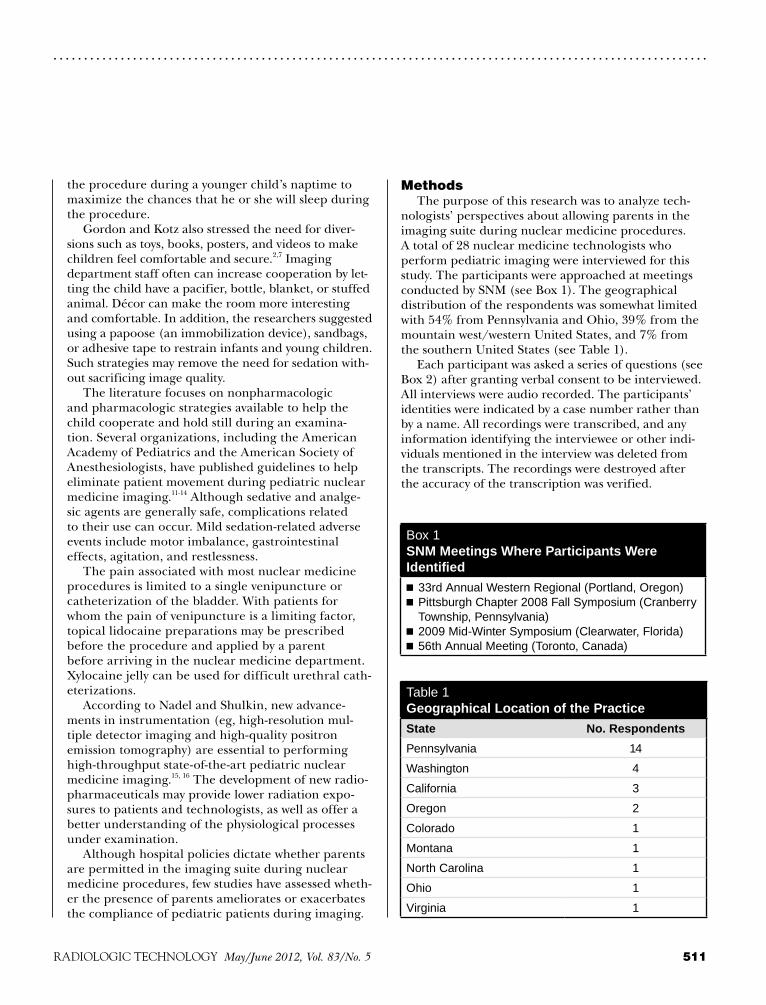
511RADIOLOGIC TECHNOLOGY May/June 2012, Vol. 83/No. 5
. . . . . . . . . . . . . . . . . . . . . . . . . . . . . . . . . . . . . . . . . . . . . . . . . . . . . . . . . . . . . . . . . . . . . . . . . . . . . . . . . . . . . . . . . . . . . . . . . . . . . . . . . . .
MethodsThe purpose of this research was to analyze tech-
nologists’ perspectives about allowing parents in the imaging suite during nuclear medicine procedures. A total of 28 nuclear medicine technologists who perform pediatric imaging were interviewed for this study. The participants were approached at meetings conducted by SNM (see Box 1). The geographical distribution of the respondents was somewhat limited with 54% from Pennsylvania and Ohio, 39% from the mountain west/western United States, and 7% from the southern United States (see Table 1).
Each participant was asked a series of questions (see Box 2) after granting verbal consent to be interviewed. All interviews were audio recorded. The participants’ identities were indicated by a case number rather than by a name. All recordings were transcribed, and any information identifying the interviewee or other indi-viduals mentioned in the interview was deleted from the transcripts. The recordings were destroyed after the accuracy of the transcription was verified.
the procedure during a younger child’s naptime to maximize the chances that he or she will sleep during the procedure.
Gordon and Kotz also stressed the need for diver-sions such as toys, books, posters, and videos to make children feel comfortable and secure.2,7 Imaging department staff often can increase cooperation by let-ting the child have a pacifier, bottle, blanket, or stuffed animal. Décor can make the room more interesting and comfortable. In addition, the researchers suggested using a papoose (an immobilization device), sandbags, or adhesive tape to restrain infants and young children. Such strategies may remove the need for sedation with-out sacrificing image quality.
The literature focuses on nonpharmacologic and pharmacologic strategies available to help the child cooperate and hold still during an examina-tion. Several organizations, including the American Academy of Pediatrics and the American Society of Anesthesiologists, have published guidelines to help eliminate patient movement during pediatric nuclear medicine imaging.11-14 Although sedative and analge-sic agents are generally safe, complications related to their use can occur. Mild sedation-related adverse events include motor imbalance, gastrointestinal effects, agitation, and restlessness.
The pain associated with most nuclear medicine procedures is limited to a single venipuncture or catheterization of the bladder. With patients for whom the pain of venipuncture is a limiting factor, topical lidocaine preparations may be prescribed before the procedure and applied by a parent before arriving in the nuclear medicine department. Xylocaine jelly can be used for difficult urethral cath-eterizations.
According to Nadel and Shulkin, new advance-ments in instrumentation (eg, high-resolution mul-tiple detector imaging and high-quality positron emission tomography) are essential to performing high-throughput state-of-the-art pediatric nuclear medicine imaging.15, 16 The development of new radio-pharmaceuticals may provide lower radiation expo-sures to patients and technologists, as well as offer a better understanding of the physiological processes under examination.
Although hospital policies dictate whether parents are permitted in the imaging suite during nuclear medicine procedures, few studies have assessed wheth-er the presence of parents ameliorates or exacerbates the compliance of pediatric patients during imaging.
Box 1SNM Meetings Where Participants Were Identified■ 33rd Annual Western Regional (Portland, Oregon)■ Pittsburgh Chapter 2008 Fall Symposium (Cranberry Township, Pennsylvania)■ 2009 Mid-Winter Symposium (Clearwater, Florida)■ 56th Annual Meeting (Toronto, Canada)
Table 1Geographical Location of the Practice
State No. Respondents
Pennsylvania 14
Washington 4
California 3
Oregon 2
Colorado 1
Montana 1
North Carolina 1
Ohio 1
Virginia 1

CASE STUDY
512 May/June 2012, Vol. 83/No. 5 RADIOLOGIC TECHNOLOGY
. . . . . . . . . . . . . . . . . . . . . . . . . . . . . . . . . . . . . . . . . . . . . . . . . . . . . . . . . . . . . . . . . . . . . . . . . . . . . . . . . . . . . . . . . . . . . . . . . . . . . . . . . . .
showed that 71% (20) of the interviewees did not have any input into the creation of a policy.
Participants identified care, comfort, concern, and cooperation as themes that helped boost com-pliance from the children and were the impetus in the creation of a policy. One technologist stated that because children are minors, parents or legal guard-ians have an established right to be present during medical procedures.
When the respondents were asked whether a parent’s presence helped or hurt the performance of the study, different opinions emerged. In regards to “helping” situations, 46% (13) were in favor of parents being pres-ent in the imaging room and 46% (13) stated that it depended on the situation. Researchers identified 4 fac-tors involved in the case-by-case response:
■ The child.■ The parent.■ The relationship between the child and the parent.■ The study being performed. Only 7% (2) of the participants indicated that paren-
tal presence “hinders” or “hurts” the study. Some respon-dents mentioned that parents can be difficult and, in those situations, the presence of a parent may need to be “dealt” with on a case-by-case basis.
When asked to describe an instance in which a par-ent’s presence was positive or negative, both situations were identified. One participant described a parent talking the patient through the procedure and calm-ing him with her voice. Another participant reflected that with a teenage girl patient, the mother was crying regarding the injection yet the patient was fine. The patient actually asked that her mother be removed from the imaging room.
The final question in the interview asked the respon-dents to discuss changes they would make as the policy author. Of the participants, 79% (22) stated that they
ResultsDemographics
Of the participants interviewed, 10 were men and 18 were women. Of these participants, the highest level of education completed was a doctorate and the lowest educational level was a 2-year associate degree. Most participants (13) had a bachelor’s degree. The years of experience were similarly distributed with an average of 16.3 years of pediatric imaging experience and an average of 17.3 years in the field of nuclear medicine technology. Participants also were asked how many procedures per month were performed at their institution (see Table 2).
Participant ResponsesAll the participants indicated that their hospital’s
policies allow parents in the imaging suite during pedi-atric examinations. Of the interview responses, 68% (19) indicated that policies were verbal (ie, unwritten but understood) and 25% (7) indicated that their facil-ities had a formal written policy. In addition, 7% (2) of the respondents stated that the policies were communi-cated in both verbal and written form.
When the respondents were asked who created the policy, the results showed that the highest percentage noted senior hospital administrators at 64% (18). Only 4% (1) of policies were developed by nuclear medicine department administrators and 18% (5) were created by technologists. Two respondents stated that they were not sure and 2 did not have a policy. The results
Box 2 Interview Questions
1. What is your hospital’s policy on allowing parents in the imaging suite during pediatric nuclear medicine?
2. Who do you think developed this policy? Did you have any input in the development of this policy?
3. What reason has been offered for that policy? 4. Do you feel that a parent’s presence helps or hurts
in the performance of the study?5. Can you describe an instance in which a parent’s
presence was positive?6. Can you describe an instance in which a parent’s
presence was negative?7. If you had the opportunity to change your hospital’s
policy regarding parents in the imaging suite during pediatric nuclear medicine imaging, what change(s) would you make? Why?
8. Do you have any other thoughts or comments?
Table 2Pediatric Procedures per Month
Procedures per Month n (%)
< 5 9 (32.14)
5-10 8 (28.57)
11-20 3 (10.71)
21-30 0 (0)
31-40 1 (3.57)
> 40 7 (25)

513RADIOLOGIC TECHNOLOGY May/June 2012, Vol. 83/No. 5
. . . . . . . . . . . . . . . . . . . . . . . . . . . . . . . . . . . . . . . . . . . . . . . . . . . . . . . . . . . . . . . . . . . . . . . . . . . . . . . . . . . . . . . . . . . . . . . . . . . . . . . . . . .
policy goals and requirements. When developing a writ-ten policy, management has an obligation to identify those who will be directly affected by the policy and to consider their views in policy development.
Although the results are interesting, a more compre-hensive study designed to address the limited geographi-cal distribution of respondents and small sample size are probably warranted.
References1. Christian PE, Waterstram-Rich KM, eds. Nuclear Medicine
and PET/CT: Technology and Techniques. 6th ed. St Louis, MO: Mosby; 2007.
2. Gordon I. Issues surrounding preparation, information and handling the child and parent in nuclear medicine. J Nucl Med. 1998;39(3):490-494.
3. Mettler FA, Guiberteau MJ. Essentials of Nuclear Medicine Imaging. 5th ed. Philadelphia, PA: Saunders Elsevier; 2006.
4. Sandler MP, Coleman RE, Patton JA, Wackers FJ, Gottschalk A, eds. Diagnostic Nuclear Medicine. 4th ed. Philadelphia, PA: Lippincott Williams & Wilkins; 2003.
5. Treves ST, ed. Pediatric Nuclear Medicine/PET. 3rd ed. New York, NY: Springer; 2007.
6. Ziessman HA, O’Malley JP, Thrall JH. Nuclear Medicine: The Requisites. 3rd ed. Philadelphia, PA: Mosby; 2006.
7. Kotz D. Pediatric nuclear medicine: special issues, unique clinical studies. J Nucl Med. 1998;39(3):13N-14N, 26N.
8. Roberts EG, Shulkin BL. Technical issues in perform-ing PET studies in pediatric patients. J Nucl Med Technol. 2004;32(1):5-9.
9. Veitch TA. Pediatric nuclear medicine, part I: developmen-tal cues. J Nucl Med Technol. 2000;28(1):3-7.
10. Veitch TA. Pediatric nuclear medicine, part II: com-mon procedures and considerations. J Nucl Med Technol. 2000;28(2):69-75.
11. American Academy of Pediatrics; American Academy of Pediatric Dentistry, Coté CJ, Wilson S; Work Group on Sedation. Guidelines for monitoring and management of pediatric patients during and after sedation for diag-nostic and therapeutic procedures: an update. Pediatrics. 2006;118(6):2587-2602.
12. Hoffman GM, Nowakowski R, Troshynski TJ, Berens RJ, Weisman SJ. Risk reduction in pediatric procedural seda-tion by application of an American Academy of Pediatrics/American Society of Anesthesiologists process model. Pediatrics. 2002;109(2):236-243.
13. Malvivya S, Voepel-Lewis T, Prochaska G, Tait AR. Prolonged recovery and delayed effects of sedation for diagnostic imaging studies in children. Pediatrics. 2000;105(3):E42.
14. Polaner DM, Houck CS, Rockoff MA, et al. Sedation, risk, and safety: do we really have data at last? Pediatrics.
were satisfied with their institution’s current pediatric policy regarding parents in the imaging room. One par-ticipant was writing a policy, and 18% (5) recommended minor modifications to their current policies such as only 1 parent, no siblings, and granting the nuclear medicine technologist the authority to evaluate on a case-by-case basis. Of the 5 respondents who preferred a modified policy, 1 respondent believed that both parents should have the right to be present and not just 1 parent as her current policy indicated.
DiscussionThis research revealed that the hospitals of all 28
technologists interviewed allowed parents in the imag-ing suite during pediatric nuclear medicine examina-tions. However, this research indicated that most policies regarding whether parents were permitted in the imag-ing room were verbal and unwritten. Written policies typically are edited carefully to address the key issues and updated regularly to offer guidance regarding the roles, responsibilities, and continuity of pediatric patient care. Written policies also avoid misunderstandings that can lead to contentious situations.
In general, at institutions with a written policy, the nuclear medicine technologist had limited input into the policy creation. However, soliciting input from the staff responsible for and affected by a policy is integral to implementation. Management can gain valuable buy-in when the responsible nuclear medicine technologist assists in policy development. Nevertheless, the results indicate overall contentment with institutions’ current pediatric policies (written or verbal) regarding parents’ presence in the imaging room.
Regarding the reason for creating a policy, the participants reflected that the health and safety of the pediatric patient is the main objective. They must deliver effective and safe medical imaging.
ConclusionThis study sought to elicit the views of experienced
nuclear medicine technologists regarding pediatric nuclear medicine practices. Specifically the focus of this work related to the presence of parents in the nuclear medicine suite. Most respondents indicated an overall contentment with their institutions’ current pediatric policies regarding parents’ presence in the imaging room. However, the majority of the respondents speci-fied that there was no written policy documented.
A written policy should be clear and concise to ensure all parties involved have the same understanding of the

CASE STUDY
514 May/June 2012, Vol. 83/No. 5 RADIOLOGIC TECHNOLOGY
. . . . . . . . . . . . . . . . . . . . . . . . . . . . . . . . . . . . . . . . . . . . . . . . . . . . . . . . . . . . . . . . . . . . . . . . . . . . . . . . . . . . . . . . . . . . . . . . . . . . . . . . . . .
2001;108(4):1006-1008. 15. Nadel HR. Where are we with nuclear medicine in pediat-
rics? Eur J Nucl Med. 1995;22(12):1433-1451.16. Shulkin BL. PET imaging in pediatric oncology. Pediatr
Radiol. 2004;34(3):199-204.
Donna L Mason, MS, R.T.(N), CNMT, is an assistant professor and clinical coordinator for the nuclear medicine technology program at Robert Morris University in Moon Township, Pennsylvania. In addition to teaching, her respon-sibilities involve the planning, coordination, administration, and monitoring of the nuclear medicine technology students at each clinical site. Ms Mason received her master of science degree in professional leadership from Carlow University in Pittsburgh, Pennsylvania.
Angela Macci Bires, EdD, MPM, R.T.(N), CNMT, is an associate professor and program director for the nuclear medicine technology program, as well as department head of health scienc-es, at Robert Morris University. She has demonstrated her com-mitment to academic excellence through the successful completion of her doctoral degree in education from Duquesne University in Pittsburgh and her master’s degree in public management, health care administration, and marketing at Carnegie Mellon University in Pittsburgh.
AcknowledgementThis work was supported by a grant from the ASRT
Education and Research Foundation.

MANAGEMENT TOOLBOX. . . . . . . . . . . . . . . . . . . . . . . . . . . . . . . . . . . . . . . . . . . . . . . . . . . . . . . . . . . . . . . . . . . . . . . . . . . . . . . . . . . . . . . . . . . . . . . . . . . . . . . . . . .
515RADIOLOGIC TECHNOLOGY May/June 2012, Vol. 83/No. 5
James H Taylor III
“Management Toolbox” focuses on practical issues concerning radiology department manage-ment and professional growth.
Close Encounters of the Patient KindAlthough health care management
often attempts to define patient satisfac-tion, the patient’s health care experi-ence likely is the best way to understand patient satisfaction.1 Most patients have expectations for their health care expe-rience, and it is reasonable to assume that patient satisfaction is a summation of their expectations.2
Improving patient satisfaction is about enhancing the patient’s experi-ence while in your care, and it also can result in a more positive patient evalu-ation for your facility.3 Most imaging departments fail to recognize factors valued by patients that could lead to increased patient satisfaction.
Medical Imaging and the State of Health Care
Although the United States faces health care reform, there is concern that principals and concepts of qual-ity in the health care system are being lost. Overwhelming evidence gathered from the past 20 years has indicated that quality of medical care processes and outcomes in the United States are less than optimal.4 According to a sur-vey conducted by the Employee Benefit Research Institute, only 53% of insured Americans who received health care services said they were extremely or very satisfied with the care they received.5 The survey results revealed a discrep-ancy between the current state of health care and what health care could and should be.
More than 300 million medical imaging procedures are performed in the United States each year.6 The demand for medical imaging services continues to grow because of an aging population and advances in technology. Imaging professionals act as representa-tives of their respective departments and have a significant influence on the patient care being given every day. Challenging your imaging department to focus on patient-centric care can
play a substantial role in achieving the highest level of patient satisfaction.
Patient Satisfaction Makes Business SenseThe dismantling of regulations and
economic factors has made the health care industry substantially immune to competition. As a result, medical imag-ing has become a true customer-oriented industry with patient satisfaction as the main focus.7 Radiologic technologists are starting to see their departments shift to a more patient-centric focus with a better understanding of the patient satisfaction phenomenon. This shift is important because patient satisfaction is a lead-ing indicator of quality and financial performance.8 When patient satisfaction improves, there is an increase in return visits, word-of-mouth referrals, new patients, and ultimately revenue.8
Word of Mouth and Patient LoyaltyWord-of-mouth referral is the most
influencial factor for a patient when it comes to choosing a health care facility.9 A hospital’s estimated cost to recapture a dissatisfied customer ranges from a con-servative estimate of $8000 per patient to approximately $400 000 a year in future encounters over that customer’s lifetime.9 The average “wronged” customer will tell 25 people about the bad experience.10 Word-of-mouth marketing — both posi-tive and negative — is a powerful force for imaging departments and it can be a driv-ing factor for reputation and revenue.10
Radiologic technologists must strive to ensure that the service provided stands above the competition to gain patient loyalty.11 The relationship between patient satisfaction, loyalty, and profitability has been well estab-lished. A 5% improvement in cus-tomer retention can lead to a 25% to 100% increase in profits.8 It costs 10 times as much to attract new custom-ers as it does to keep current ones.10 Systematically improving patient sat-isfaction to maximize the number of

MANAGEMENT TOOLBOX
516 May/June 2012, Vol. 83/No. 5 RADIOLOGIC TECHNOLOGY
. . . . . . . . . . . . . . . . . . . . . . . . . . . . . . . . . . . . . . . . . . . . . . . . . . . . . . . . . . . . . . . . . . . . . . . . . . . . . . . . . . . . . . . . . . . . . . . . . . . . . . . . . . .
patients who are fiercely loyal to the organization can mean more reliable revenue from patients and their families, and less cost to attract new patients.10
Compassion of health care practitioners appears to be the most important influence on patient inten-tions to recommend the services or return as a patient, regardless of the setting in which the care is provided.10
This level of commitment requires an understanding of the health care market and an understanding of the consumers as people, not just patients.11
The Patient’s Role Imaging is unique among health care professions
that involve customer relations. The time technolo-gists spend with patients is minimal and usually lim-ited by scheduling constraints. Technologists must use their time wisely to establish a trusting and profes-sional relationship with the patient and ensure proper patient care.
Inherent Obstacles in Patient SatisfactionCustomer Choice
The disparity in status between the provider and receiver of health care services is monumental in radi-ology. No other service industry imposes so great a distinction. From the moment the patient enters the health care facility, the subordinate role is established and reinforced. The relationship between the patient and the technologist is established even before the patient arrives at the facility.7 In general, patients do not desire or elect to have a diagnostic exam. Usually the selection of an imaging facility involves customer choice. However, hospitalization is generally a matter of necessity, and this has afforded caregivers greater lee-way to define the terms of the relationship with their clientele.7 Because of this factor and other barriers to providing patient-centric care, radiologic imaging is less likely to be distinguished by customer service than other industries.7 Patients expect to receive a basic level of care, but practicing patient-oriented care can sepa-rate an imaging facility from its competition.
Evolution of the PatientImaging departments must evolve to overcome new
challenges and barriers to providing patient-centric care that have been in place for quite some time.7 As the baby boomer generation ages, they will expect consistent, high-quality health care.7 Also, in this patient-centric environment, health care professionals can expect better informed patients. This new breed of customer will come
armed with information from the Internet and questions about products they have learned about through market-ing and advertising.13 Patients may take a more active role in their care and expect to be engaged partners in deci-sions concerning their health.13
As the patient demands a patient-centric environ-ment, health care facilities will see several workplace changes. Hospital Consumer Assessment of Healthcare Providers and Systems is a new Internet-based service for patients that provides publicly available data with results from a national, standardized survey of patient experiences. Services such as this show the importance of patient satisfaction.9 Imaging departments can bene-fit by restructuring the work environment to encourage and reinforce customer service.7
Road to Patient SatisfactionTo provide optimal care, imaging departments
must find ways to overcome inevitable and unchang-ing obstacles. Enhancing a patient’s experience can be achieved through 5 key drivers of patient satisfaction:
■ Understanding. ■ Quality. ■ Informed communication. ■ Timeliness.■ Value.12
By understanding their patients’ needs, caregivers demonstrate respect for their patients’ values and pref-erences.12 This involves being empathetic to a patient’s circumstances by actively listening and maintaining eye contact with patients during conversation.
Patients expect safe, quality, and customized health care.12 It is important to create an environment that encourages technologists to go above the patients’ basic expectations. Owning the experience can fulfill quality expectations. This involves customizing every patient experience by tailoring the care to a patient’s needs and wants. Patients are beginning to pay more and demand better quality service, and they will go elsewhere if they do not receive it.
Patients want a certain level of communication and want the technologist to be knowledgeable and able to answer questions.12 Active listening and acknowledg-ment of a patient’s concerns expresses sincerity and can make his or her experience less frightening and uncomfortable.3 Patients also want communication about the potential outcomes or risks involved in the procedure to be able to make the best decisions for themselves.12 Too often patients are rushed and not informed about a test or procedure. Technologists must

517RADIOLOGIC TECHNOLOGY May/June 2012, Vol. 83/No. 5
. . . . . . . . . . . . . . . . . . . . . . . . . . . . . . . . . . . . . . . . . . . . . . . . . . . . . . . . . . . . . . . . . . . . . . . . . . . . . . . . . . . . . . . . . . . . . . . . . . . . . . . . . . .
not forget their obligation to inform patients about procedures. This will relieve patient anxiety and help prevent technologist liability in a lawsuit. Patients also desire a clear understanding of their follow-up treat-ment after a diagnostic examination. Technologists must be thorough in these instructions to prevent inju-ries to their patients. Finally, at the end of the exam, technologists should ask, “Is there anything else I can help you with today?” This influences a patient’s experi-ence and can provide assurance that the patient is fully satisfied with his or her health care experience.
Patients want to receive care in a timely manner and want to receive test and treatment results promptly.12,13 Even though the ordering physician is usually responsi-ble for explaining test outcomes, patients do not always receive them. One study found that 72% of physicians did not inform patients when test results were normal, and only 55% always informed patients when results were abnormal.14 Patients do not always know who to contact when a problem arises, and they may blame the radiology department for not keeping them informed.14 Managers should remind technologists to inform patients about their timeline of care at the end of their exam. Making sure patients know what to expect next helps minimize confusion and allows patients to have an active role in their care.
Many patients feel there is disconnect between “what they pay for” and “what they get.”12 Patients expect value from their health care experience as they become responsible for more of their health care bills.12
Tools for Evaluating Patient SatisfactionIt is important to evaluate patient satisfaction by
measuring the degree to which patient expectations are being met. This is the only way to fulfill patients’ needs and to improve future patients’ experiences.
Imaging departments commonly use questionnaires. When used, they should measure whether the patient was satisfied and hospital care was of sufficient qual-ity.15 Data concerning the reliability and validity of questionnaires used in imaging departments are not currently available for analysis. However, questionnaires used in a hospital setting have been very reliable and demonstrate high precision for measuring patient satis-faction and establishing overall hospital care quality.15
Achieving R.T. and Patient SatisfactionThe satisfaction of radiologic technologists and
patients are intertwined. Many surveys show empirical evidence that patient perception of the care they receive
at a facility has a positive correlation with employee per-ception of the facility.16 These studies indicate that if an employee is unhappy, it reflects negatively on a patient’s perception of care. A satisfied workforce has been known to have lower turnover rates, increased productivity, better care, and an enhanced patient experience. Poor service quality is not usually caused by apathetic staff and unwilling managers, but by a system that fails to support them.17 The intent of every radiologic technologist is to provide high-quality service, and it is the responsibility of management to make that possible by developing a cul-ture where staff members can best perform.12
Improving R.T. Satisfaction Value and Empowerment
An essential aspect of great patient care is the tech-nologist’s ability to respond in a virtually spontaneous manner to the needs of patients.7 The effectiveness of the imaging staff is contingent on the freedom to act on behalf of the patients’ needs.7 By allowing technologists the autonomy to make decisions needed to provide qual-ity care, their job satisfaction and commitment to the department will increase.18 A successful hospital environ-ment is created by encouraging employees to act inde-pendently, and allows staff members to exercise greater flexibility and resourcefulness to solve problems as they occur.7 Staff empowerment is an empty slogan unless it is reinforced by management through a system of encour-agement.7 Technologists need to know their department has a standard of quality patient care.
Meaningful WorkRadiologic technologists desire a work process
design that is centered on patients and the needs of staff members. This begins with management. When management communicates the “hows” and “whys” of their formula in making decisions effectively, the sys-tem allows technologists to be more effective.
Training, Development, and Growth OpportunitiesEducational opportunities are important for technolo-
gists and allow for personal growth, professional develop-ment, and up-to-date best practices.7 Technologists want to be in an encouraging workspace. This atmosphere is beneficial to management because it allows them to delegate otherwise time-consuming tasks to technolo-gists. At the same time, delegating allows technologists to be challenged to reach their full potential and provides them with an understanding of tasks related to manag-ing the department.

MANAGEMENT TOOLBOX
518 May/June 2012, Vol. 83/No. 5 RADIOLOGIC TECHNOLOGY
. . . . . . . . . . . . . . . . . . . . . . . . . . . . . . . . . . . . . . . . . . . . . . . . . . . . . . . . . . . . . . . . . . . . . . . . . . . . . . . . . . . . . . . . . . . . . . . . . . . . . . . . . . .
ConclusionAlthough some suggestions in this article may
seem fundamental, many health care providers fail to understand the significance of their role in patient satisfaction. Radiologic technologists must become continuous learners of the emerging patterns of a patient’s expectation of care, and also must develop a more patient-focused view that fulfills the mis-sion of health care. Patient-oriented care is directly related to better health outcomes, and it is important for addressing health care disparities. It takes into account patients’ personal and social contexts and involves tailoring communication, education, and health care to patient values and needs.19
Managers must enhance the work environment to increase radiologic technologists’ satisfaction as employ-ees, which will have a significant effect on patient satisfac-tion in imaging departments everywhere.
References1. Lucassen P. The quality dilemma. Prim Care Diabetes.
2007;1(2):107-110.2. Shur R, Simons N. Quality issues in health care research
and practice. Nurs Econ. 2008;26(4):258-262.3. Worthington K. Customer satisfaction in the emergency
department. Emerg Med Clin North Am. 2004;22(1):87-102.4. Solberg LI, Taylor N, Conway WA, Hiatt RA. Large mul-
tispecialty group practices and quality improvement: what is needed to transform care? J Ambul Care Manage. 2007;30(1):9-17.
5. Uninsured are more likely than insured to be dissatis-fied with quality of the health care they receive, study says [press release]. Washington, DC: Employee Benefit Research Institue; September 9, 2009. www.ebri.org/pdf /PR.848_09Sept09.HCS.pdf. Accessed April 18, 2010.
6. Who’s taking your x-ray? Radiol Technol. 2007;79(1):104.7. Eisenberg B. Customer service in health care: a new era.
Hosp Health Serv Adm. 1997;42(1):17-31.8. Drain M. Will your patients return? The foundation for
success. Press Ganey website. www.pressganey.com/news Landing/10-09-18/Will_Your_Patients_Return_The_Foundation_for_Success.aspx. Accessed April 18, 2010.
9. Johnson CG. “Knock-your-socks-off” service. Nurs Manage. 1999;30(7):16-19.
10. Press Ganey Associates Inc. Return on investment: patient loyalty pays. Press Ganey website. www.pressganey.com /newsLanding/10-09-24/Return_on_Investment_Patient_Loyalty_Pays.aspx. Accessed April 18, 2010.
11. Howland-Gradman J, Broderick S. Soar to excellence with rapid feedback and rapid response. Nurs Manage. 2002;33(2):43, 45.
CommunicationAn open, blame-free environment will support col-
laboration and demonstrate management’s commit-ment to the organization.12 When technologists feel they can speak freely in an appropriate setting with-out fear of retaliation, serious issues can be addressed and solved. Technologists are at the forefront of the patient care experience and can help pinpoint the problems and successes in department processes. Managers must develop a culture where technologists are encouraged to communicate if they wish to have an engaged partner in the patient experience and want their department to be patients’ first choice for medical imaging.17
Recognition and Compensation Recognition of top-level performance motivates
employees.12 Every employee wants acknowledgment but not always in a public setting. Most departments use plaques or certificates but, for some, a few words behind closed doors can have an encouraging effect. Knowing the staff and the importance of recognition to them can increase morale and set high standards for the department.
Financial Effect of Patient-centric Caring Increased demands on the technologist from man-
agement to maximize work and increase the revenue has resulted in overlooking the importance of good patient care. Creating a patient-centric environment takes time and may be seen as a deterrent in gen-erating revenue for the department.20 Contrary to the thinking that quality means sparing no expense, the pursuit of high quality can lead to substantially reduced cost and increased revenue. Imaging per-sonnel who practice patient-centric caring also can help in avoiding unnecessary costs to the facility. Patient-centric care can influence timeliness of pro-cedures by reducing patient stress and creating a positive relationship. Increasing patient confidence going into an examination uses the exam time effi-ciently and can help prevent nondiagnostic exams and patient callbacks. In addition, practicing patient-centric care may help prevent litigation, which car-ries high costs.20
Establishing an imaging department that practices patient-centric care has several positive outcomes, including employee and patient satisfaction, more effi-cient processes, liability protection, and a more reward-ing caregiver experience.

519RADIOLOGIC TECHNOLOGY May/June 2012, Vol. 83/No. 5
. . . . . . . . . . . . . . . . . . . . . . . . . . . . . . . . . . . . . . . . . . . . . . . . . . . . . . . . . . . . . . . . . . . . . . . . . . . . . . . . . . . . . . . . . . . . . . . . . . . . . . . . . . .
12. Runy LA. The dynamics of satisfaction. Hosp Health Netw. 2002;76(11):57-63, 2.
13. Morrison G. Trends in the health care workplace. Radiol Technol. 2006;77(6):433-435.
14. Scott A. Improving communication for better patient care. Radiol Technol. 2007;78(3):205-218.
15. Hendriks AA, Oort FJ, Vrielink MR, Smets EM. Reliability and validity of the satisfaction with hospital care question-naire. Int J Qual Health Care. 2002;14(6):471-482.
16. Geyer S. Hand in hand: patient and employee satisfaction. Trustee. 2005;58(6):12-14, 19, 1.
17. Leebov W. Reducing patient anxiety, increasing satis-faction. Interview by Bill Santamour. Hosp Health Netw. 2009;83(7):16.
18. Watson LM. Factors influencing job satisfaction and orga-nizational commitment. Radiol Technol. 2008;80(2):113-122.
19. Hasnain-Wynia R, Jean-Jacques M. Filling the gaps between performance incentive programs and health care quality improvement. Health Serv Res. 2009;44(3):777-783.
20. Adams R, Rush K. The economics of caring. Radiol Technol. 2007;79(1):65M-67M.
James H Taylor III, BSRS, R.T.(R)(CT)(MR), is a graduate of the University of North Carolina – Chapel Hill Radiologic Science Baccalaureate Program. He is a magnetic resonance technologist with Duke Raleigh Hospital. This is his first published work.


PATIENT PAGEw...................................................................................................................
523RADIOLOGIC TECHNOLOGY May/June 2012, Vol. 83/No. 5
This patient education page provides general information concerning the radiologic sciences. The ASRT suggests that you consult your physician for specific information concerning your imaging exam and medical condition. Health care professionals may reproduce these pages for noncommercial educational purposes. Reproduction for other reasons is subject to ASRT approval.
For more information visit us online at www.asrt.org.
Your First Mammogram
There’s a good reason 25 million mammo-grams, or low-dose x-ray images of the breast, are performed annually. Mammography is the best way to find breast cancer during its early, more treat-able stages. The American Cancer Society recom-mends that women receive annual mammograms after age 40.
Before the ExaminationTry to schedule your mammogram for the week
following your menstrual period, when your breasts are less tender. Wear a two-piece outfit to the examination, so you only will have to remove your top. Do not apply underarm deodorant, powders, ointments, or creams to your chest area the day of the exam because these products can show up on the x-ray images and make them difficult to inter-pret. Be sure to bring the name, address, and phone number of the physician who referred you for the mammogram. If you are going to a facility for the first time, bring a list of the places and dates of your past mammograms, biopsies, or other breast treat-ments. In addition, if you have had mammograms at another facility, you should try to get your most recent x-ray films or digital pictures to bring with you to the new facility (or have them sent there). It is important for the radiologist to be able to com-pare the past images to the new ones.
Before the examination, you will be asked to undress from the waist up and put on an examination gown. A mammographer will perform your examina-tion. Mammographers are skilled medical profession-als who have received specialized education in the areas of mammographic positioning and techniques.
During the Examination The mammographer will ask you to stand in
front of the mammography unit, a special type of x-ray machine. She will place one of your breasts on a small platform attached to the machine. The platform can be raised or lowered to match your height. Your breast then will be gradually compressed between two clear plastic plates. For screening mam-mography, two images are taken of the breast, one from the top and one from the side. Some patients, such as those with large breasts, may need to have more images taken to ensure the physician can see as
much breast tissue as possible. The examination then is repeated for the other breast. Compression spreads and flattens the breast tissue. It ensures a clear pic-ture and reduces the amount of radiation necessary for the x-ray image.
Compression may be uncomfortable, but it should not hurt. Let the mammographer know if the com-pression is painful, and he or she will try to reposi-tion you to minimize discomfort. Actual compression time is only a few seconds. If you are worried about discomfort, tell your physician. You may be advised to take a mild over-the-counter pain reliever about an hour before your examination.
You will be asked to wait a few minutes while the x-ray images are checked. The mammographer will determine if the images are technically acceptable or if additional views are necessary. Do not be alarmed if you are asked to return for additional images.
After the ExaminationThe mammography images will be given to a
radiologist, a physician who specializes in the diag-nostic interpretation of medical images. Under federal regulations, the radiologist must be experi-enced in reading mammographic images.
The radiologist will send your personal physician a report of the findings, and you will receive a written summary of the report in lay terms. If you have not received your results within one month, contact your physician or the mammography facility. Be sure to note the date and facility that performed your mam-mogram because that information may be necessary for future examinations. u

524 May/June 2012, Vol. 83/No. 5 RADIOLOGIC TECHNOLOGY
Esta página educacional del paciente provée información general en cuanto a la ciencia radiológica. ASRT sugiere que usted consulte con su doctor para obtener información específica concerniente a su examen de imagen y condiciones medicas. Los profesionales del cuidado de la salud pueden reproducir estas páginas para ser usadas sin recibir lucro económico. La reproducción de estos documentos para ser usadas para otros objetivos necesita la autorización del ASRT.
Para más información visítenos en la web electrónica: www.asrt.org.
. . . . . . . . . . . . . . . . . . . . . . . . . . . . . . . . . . . . . . . . . . . . . . . . . . . . . . . . . . . . . . . . . . . . . . . . . . . . . . . . . . . . . . . . . . . . . . . . . . . . . . . . . . . . . . . . . . .
PATIENT PAGE
En Español
Hay buenos motivos por los que se realizan anu-almente 25 millones de mamografías o imágenes de los senos con baja dosis de rayos X. La mamografía es la mejor manera de detectar el cáncer de los senos durante sus estadios iniciales y más tratables. La American Cancer Society recomienda que las mujeres se hagan una mamografía preventiva de referencia entre los 35 y los 40 años de edad y mamo-grafías anuales a partir de los 40 años de edad.
Antes del ExamenTrate de marcar su mamografía para la semana
después de su período menstrual, cuando sus senos están menos doloridos. Vista un traje de dos piezas para el examen; así sólo tendrá que sacarse la parte superior. No use desodorante debajo del brazo, talcos, pomadas o cremas en el área de su pecho el día del examen, pues dichos productos podrán aparecer en las imágenes de rayos X y hacer que resulten difíciles de interpretar. Asegúrese de llevar el nombre, la dirección y el número de teléfono del médico que le pidió la mamografía. Si usted visita a un centro médi-co por primera vez, traiga una lista de los lugares y las fechas de sus mamografías, biopsias y otros tratamien-tos mammographicos que ha recibido previamente. Además, si usted ha tenido una mamografía en otro centro médico, usted debe tratar de conseguir sus más recientes radiografías o imágenes digitales para llevar al centro nuevo (o que se los envíen ahí). Es importante que el radiólogo pueda comparar imá-genes anteriores contra imágenes nuevas.
Antes de su examen, se le pedirá que se desvista de la cintura hacia arriba y vista una bata de exa-men. Una tecnóloga en mamografías le realizará el examen. Las tecnólogas en mamografías son profe-sionales médicas especializadas con estudios en las áreas de posicionamiento y técnicas mamográficas.
Durante el ExamenLa tecnóloga en mamografías le pedirá que se
pare delante de la unidad de mamografía, un tipo especial de máquina de rayos X. Colocará uno de sus senos sobre una pequeña plataforma sujeta a la máquina. Se puede subir o bajar la plataforma de acuerdo con su altura. Luego, se comprimirá su seno gradualmente entre dos placas de plástico transparentes. Para la mamografía preventiva, se
toman dos imágenes del seno: una desde arriba y una desde el costado. Algunos pacientes, como aquellos con senos más grandes, pueden necesi-tar tener una cantidad más alta de imágenes para garantizar que el médico pueda ver el tejido de los senos tanto como sea posible. Luego se repite el exa-men para el otro seno. La compresión desparrama y achata los tejidos del seno. Es necesaria para que la imagen resulte clara y para reducir la cantidad de radiación necesaria para la imagen radiológica.
La compresión puede resultar incómoda, pero no debe doler. Si la compresión le hace doler, avísele a la tecnóloga en mamografías para que ella la coloque en posición nuevamente para minimizar la incomodidad. La compresión dura apenas unos segundos. Si le preocupa la incomodidad, avísele a su médico. Se le podrá aconsejar que tome un anal-gésico suave de venta libre alrededor de una hora antes de su examen.
Se le pedirá que espere unos minutos mientras se procesan las películas radiológicas. La tecnóloga en mamografías entonces determinará si las imá-genes son técnicamente aceptables o si se necesitan imágenes adicionales. No se alarme si se le pide que vuelva para imágenes adicionales.
Después del ExamenLuego, se le entrega las películas de la mamo-
grafía a un radiólogo, que es un médico especial-izado en la interpretación diagnóstica de imágenes clínicas. De acuerdo con los reglamentos federales, el(la) radiólogo(a) debe contar con experiencia en la interpretación de imágenes mamográficas.
El radiólogo le enviará a su médico personal un informe con los resultados, y usted recibirá un resumen escrito del informe, redactado con térmi-nos laicos. Si no recibió los resultados en el plazo de un mes, entre en contacto con su médico o con el establecimiento de mamografías. Asegúrese de anotar la fecha y el establecimiento que realizó su mamografía, pues dicha información podrá ser necesaria para exámenes futuros. u
Su primera mamografía

©2011 ASRT. All rights reserved.
www.asrt.org/memberperks
The Travel Discounts You Want
PerksMember
Perks
Save some moneyfor the fun stuff.

MR Basics Online Education
essentialeducation©2012 ASRT. All rights reserved.
MR Basics – Continuing EducationModule 1 – FundamentalsModule 2 – Equipment and InstrumentationModule 3 – Radiofrequency and GradientsModule 4 – Image Production ParametersModule 5 – Contrast Media
www.asrt.org/MRBasics
Module 6 – Pulse SequencesModule 7 – Safety EssentialsModule 8 – Image QualityModule 9 – NeuroimagingModule 10 – Body and Joint Imaging
A Solid
in MRFoundation
Gain the expertise you need to succeed in magnetic resonance imaging with this online educational series.
Institutional and credit versions available. Purchase the complete institutional version and get a complimentary image library and test bank. Complete the credit version and ASRT will send you a certifi cate recognizing your achievement.