radiometry and photometric stereo 1. estimate the 3d shape from shading information can you tell the...
TRANSCRIPT
Radiometry andPhotometric Stereo
1

Estimate the 3D shape from shading information
• Can you tell the shape of an object from these photos ?
2
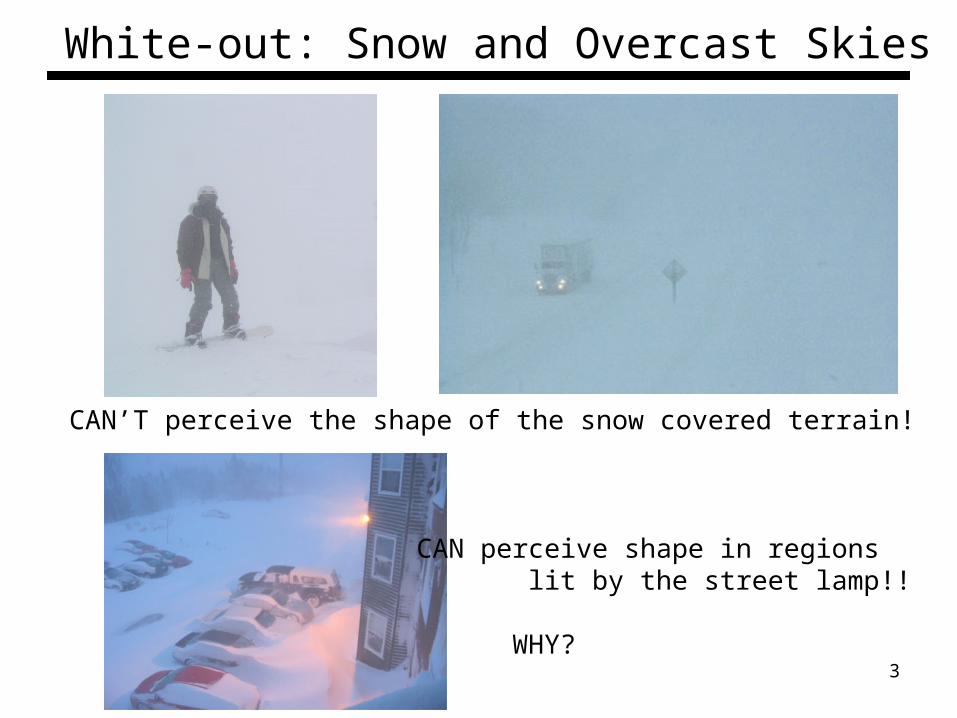
White-out: Snow and Overcast Skies
CAN’T perceive the shape of the snow covered terrain!
CAN perceive shape in regions lit by the street lamp!!
WHY?3
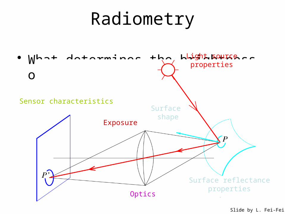
Radiometry
• What determines the brightness of an image pixel?
Light sourceproperties
Surface shape
Surface reflectanceproperties
Optics
Sensor characteristics
Slide by L. Fei-Fei
Exposure
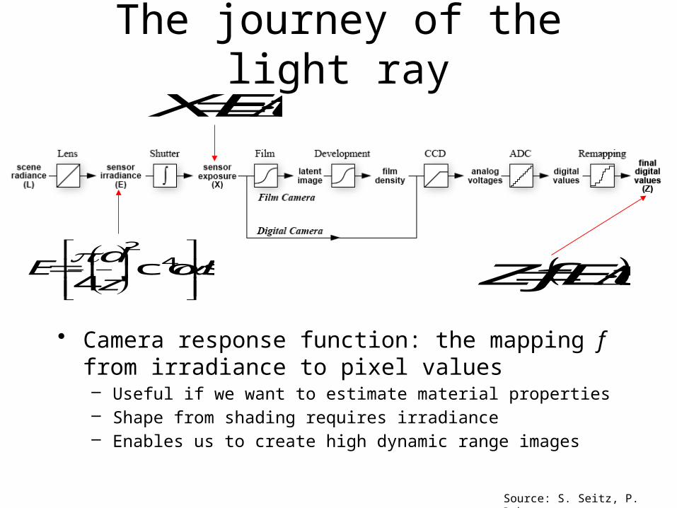
The journey of the light ray
• Camera response function: the mapping f from irradiance to pixel values– Useful if we want to estimate material properties– Shape from shading requires irradiance– Enables us to create high dynamic range images
Source: S. Seitz, P. Debevec
Lz
dE
4
2
cos'4
tEX
tEfZ
Recovering the camera response function
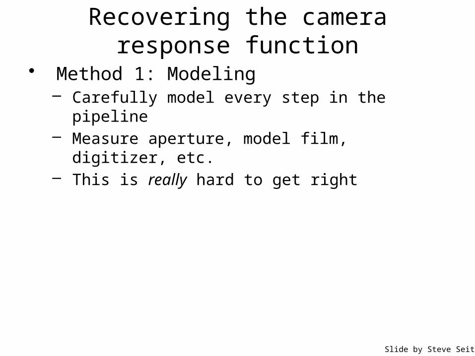
• Method 1: Modeling– Carefully model every step in the pipeline– Measure aperture, model film, digitizer, etc.– This is really hard to get right
Slide by Steve Seitz

• Method 1: Modeling– Carefully model every step in the pipeline– Measure aperture, model film, digitizer, etc.– This is really hard to get right
• Method 2: Calibration– Take pictures of several objects with known irradiance– Measure the pixel values– Fit a function
Recovering the camera response function
irradiance
pixel intensity=
response curve
Slide by Steve Seitz

Recovering the camera response function
• Method 3: Multiple exposures– Consider taking images with shutter speeds
1/1000, 1/100, 1/10, 1– The sensor exposures in consecutive images get scaled by a
factor of 10– This is the same as observing values of the response function
for a range of irradiances: f(E), f(10E), f(100E), etc.– Can fit a function to these successive values
For more info• P. E. Debevec and J. Malik.
Recovering High Dynamic Range Radiance Maps from Photographs. In SIGGRAPH 97, August 1997
response curve
Exposure (log scale) irradiance * time=
pixel intensity=
Slide by Steve Seitz

The interaction of light and matter
• What happens when a light ray hits a point on an object?– Some of the light gets absorbed
• converted to other forms of energy (e.g., heat)– Some gets transmitted through the object
• possibly bent, through “refraction”– Some gets reflected
• possibly in multiple directions at once– Really complicated things can happen
• fluorescence
• Let’s consider the case of reflection in detail– In the most general case, a single incoming ray could be reflected in all
directions. How can we describe the amount of light reflected in each direction?
Slide by Steve Seitz
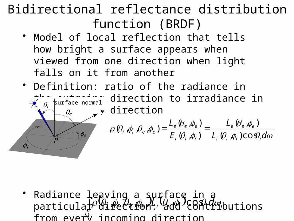
Bidirectional reflectance distribution function (BRDF)
• Model of local reflection that tells how bright a surface appears when viewed from one direction when light falls on it from another
• Definition: ratio of the radiance in the outgoing direction to irradiance in the incident direction
• Radiance leaving a surface in a particular direction: add contributions from every incoming direction
dL
L
E
L
iiii
eee
iii
eeeeeii cos),(
),(
),(
),(),,,(
surface normal
iiiiieeii dL cos,,,,,

BRDF’s can be incredibly complicated…
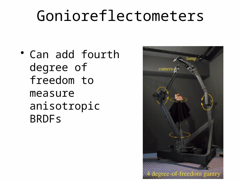
Gonioreflectometers
• Can add fourth degree of freedom to measure anisotropic BRDFs

Diffuse reflection
• Dull, matte surfaces like chalk or latex paint• Microfacets scatter incoming light randomly• Light is reflected equally in all directions: BRDF is
constant• Albedo: fraction of incident irradiance reflected by the
surface• Radiosity: total power leaving the surface per unit area
(regardless of direction)
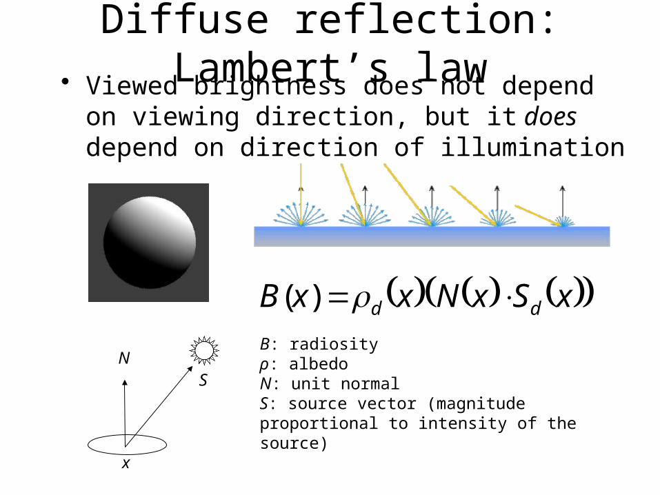
• Viewed brightness does not depend on viewing direction, but it does depend on direction of illumination
Diffuse reflection: Lambert’s law
xSxNxxB dd )(
NS
B: radiosityρ: albedoN: unit normalS: source vector (magnitude proportional to intensity of the source)
x

Specular reflection• Radiation arriving along a source
direction leaves along the specular direction (source direction reflected about normal)
• Some fraction is absorbed, some reflected
• On real surfaces, energy usually goes into a lobe of directions
• Phong model: reflected energy falls of with
• Lambertian + specular model: sum of diffuse and specular term
ncos
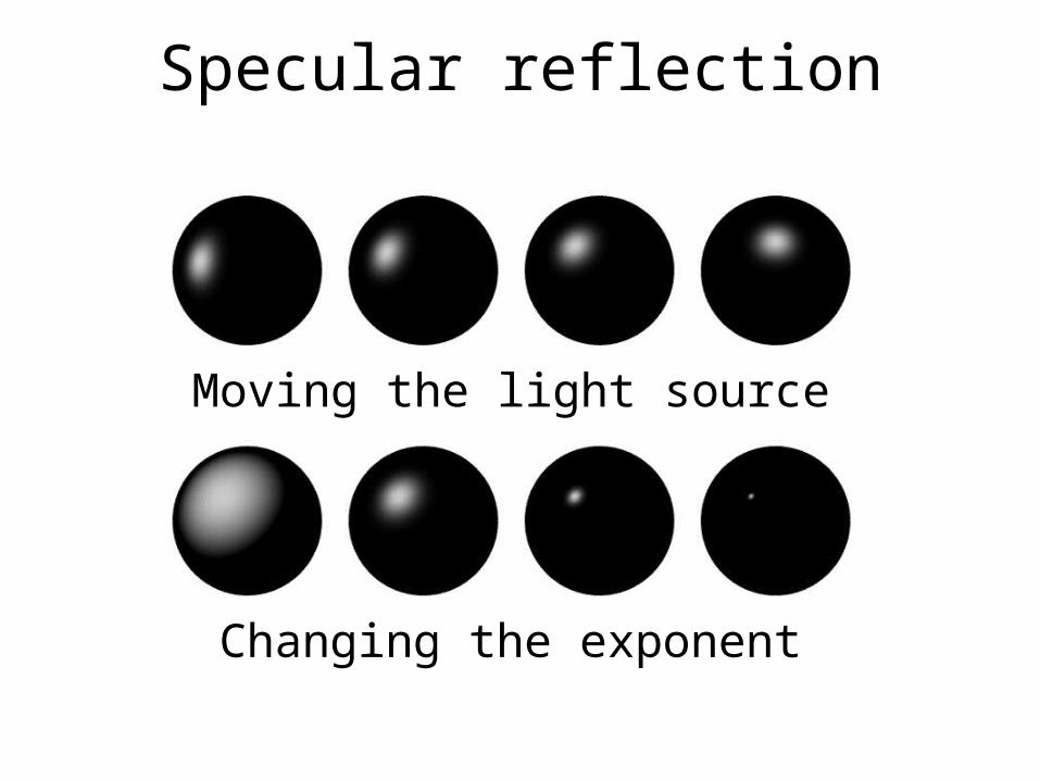
Specular reflection
Moving the light source
Changing the exponent
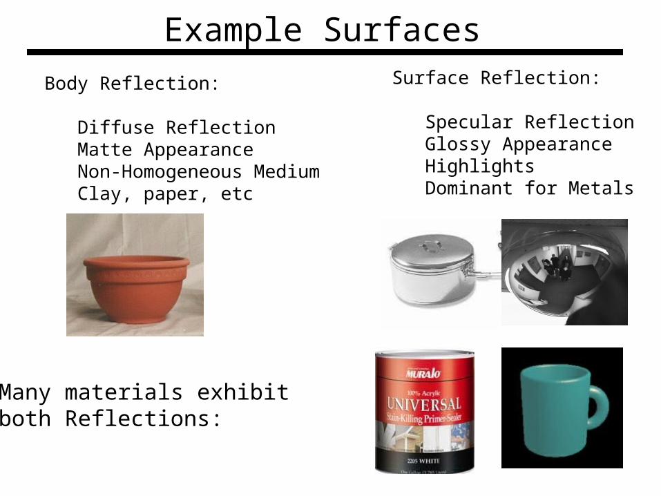
Example Surfaces
Body Reflection:
Diffuse ReflectionMatte AppearanceNon-Homogeneous MediumClay, paper, etc
Surface Reflection:
Specular ReflectionGlossy AppearanceHighlightsDominant for Metals
Many materials exhibitboth Reflections:
17

Diffuse Reflection and Lambertian BRDF
viewingdirection
surfaceelement
normalincidentdirection
in
v
s
d
rriif ),;,(• Lambertian BRDF is simply a constant :
albedo
• Surface appears equally bright from ALL directions! (independent of )
• Surface Radiance :
v
• Commonly used in Vision and Graphics!
snIIL di
d .cos
source intensity
source intensity I
18

Specular Reflection and Mirror BRDFsource intensity I
viewingdirectionsurface
element
normal
incidentdirection n
v
s
rspecular/mirror direction
),( ii ),( vv
),( rr
• Mirror BRDF is simply a double-delta function :
• Valid for very smooth surfaces.
• All incident light energy reflected in a SINGLE direction (only when = ).
• Surface Radiance : )()( vivisIL
v r
)()(),;,( vivisvviif specular albedo
19

Combing Specular and Diffuse: Dichromatic Reflection
Observed Image Color = a x Body Color + b x Specular Reflection Color
R
G
B
Klinker-Shafer-Kanade 1988
Color of Source(Specular reflection)
Color of Surface(Diffuse/Body Reflection)
Does not specify any specific model forDiffuse/specular reflection
20
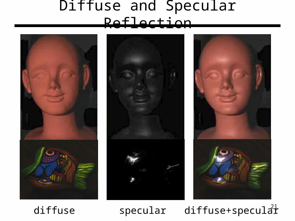
Diffuse and Specular Reflection
diffuse specular diffuse+specular 21

Image Intensity and 3D Geometry
• Shading as a cue for shape reconstruction• What is the relation between intensity and
shape?– Reflectance Map
22

Surface Normal
Nsurface normal
y
z
x
Equation of plane 0 DCzByAx
0C
Dzy
C
Bx
C
Aor
Letp
C
A
x
z
qC
B
y
z
1,,1,, qpC
B
C
A
N
Surface normal
23

Gradient Space
y
z
x
1zq
p
1
s n
N
1
1,,22
qp
qp
N
Nn
1
1,,22
SS
SS
qp
qp
S
Ss
Normal vector
Source vector
i
11
1cos
2222
SS
SSi
qpqp
qqppsn
1z plane is called the Gradient Space (pq plane)
• Every point on it corresponds to a particular surface orientation
S
24

Reflectance Map
• Relates image irradiance I(x,y) to surface orientation (p,q) for given source direction and surface reflectance
• Lambertian case: yxI ,
s vni
: source brightness
: surface albedo (reflectance)
: constant (optical system)
k
c
Image irradiance:
sn kckcI i
cos
Let 1kc
then sn iI cos25

• Lambertian case qpR
qpqp
qqppI
SS
ssi ,
11
1cos
2222
sn
Reflectance Map(Lambertian)
cone of constant i
Iso-brightness contour
Reflectance Map
26

• Lambertian case
0.1
3.0
0.0
9.08.0
7.0, qpR
p
q
90i 01 SS qqpp
SS qp ,
iso-brightnesscontour
Note: is maximum when qpR , SS qpqp ,,
Reflectance Map
27
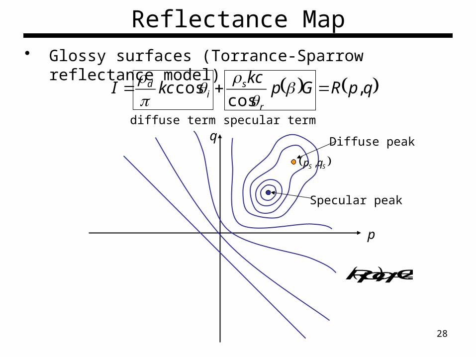
• Glossy surfaces (Torrance-Sparrow reflectance model)
qpRGpkc
kcIr
si
d ,cos
cos
diffuse term specular term
p
q
5.0, qpR
SS qp ,
Diffuse peak
Specular peak
Reflectance Map
28
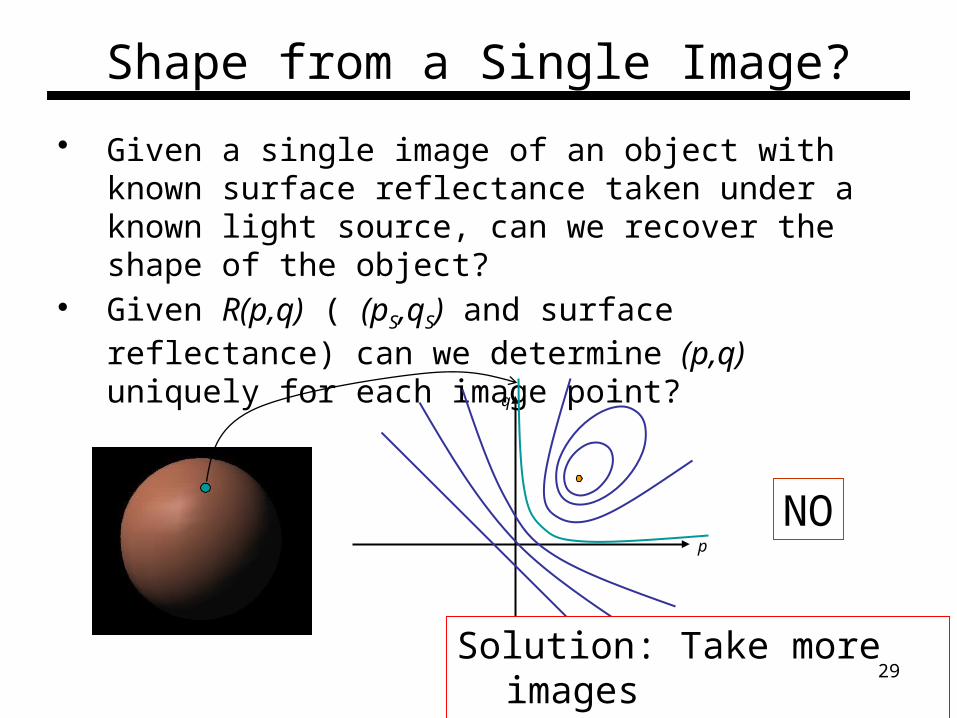
Shape from a Single Image?
• Given a single image of an object with known surface reflectance taken under a known light source, can we recover the shape of the object?
• Given R(p,q) ( (pS,qS) and surface reflectance) can we determine (p,q) uniquely for each image point?
NOp
q
Solution: Take more imagesPhotometric stereo
29

Photometric Stereo
p
q
11 ,SSqp
22 ,SSqp
33 ,SSqp
30

• We can write this in matrix form:
Image irradiance:
1kc
11 snI1s
n
v
2s
22 snI3s
33 snI
n
s
s
s
T
T
T
I
I
I
3
2
2
2
1 1
Lambertian case:
sn
ikcI cos
Photometric Stereo
31
Solving the Equations
n
s
s
s
T
T
T
I
I
I
3
2
2
2
1 1
I S n~133313
ISn 1~ n~
n
n
nn
~
~
~
inverse
32

More than Three Light Sources
• Get better results by using more lights
n
s
s
TN
T
NI
I
11
• Least squares solution:
nSI ~nSSIS ~TT
ISSSn TT 1~
• Solve for as beforen, Moore-Penrose pseudo inverse
1331 NN
33
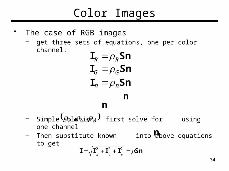
Color Images
• The case of RGB images– get three sets of equations, one per color channel:
– Simple solution: first solve for using one channel– Then substitute known into above equations to get
– Or combine three channels and solve for
SnI GG SnI BB
SnI RR
BGR ,,
n
n
SnIIII 222
BGR
n
34
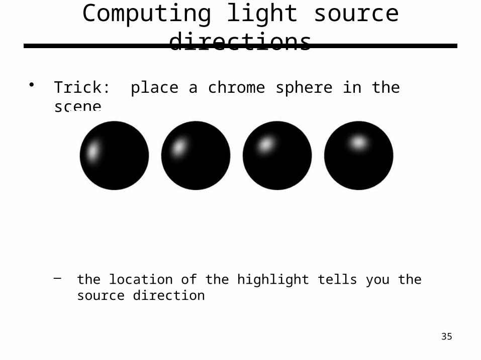
Computing light source directions
• Trick: place a chrome sphere in the scene
– the location of the highlight tells you the source direction
35

• For a perfect mirror, light is reflected about N
Specular Reflection - Recap
otherwise0
if rvie
RR
• We see a highlight when • Then is given as follows:
n
vs
rv s
rnrns 2
rii
36

Computing the Light Source Direction
• Can compute N by studying this figure– Hints:
• use this equation:• can measure c, h, and r in the image
N
rN
C
H
c
h
Chrome sphere that has a highlight at position h in the image
image plane
sphere in 3D
37
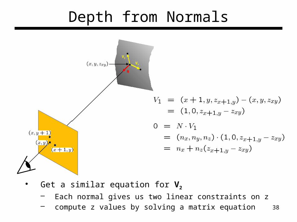
Depth from Normals
• Get a similar equation for V2
– Each normal gives us two linear constraints on z– compute z values by solving a matrix equation
V1
V2
N
38
Limitations
• Big problems– Doesn’t work for shiny things, semi-
translucent things– Shadows, inter-reflections
• Smaller problems– Camera and lights have to be distant– Calibration requirements
• measure light source directions, intensities• camera response function
39

Trick for Handling Shadows
• Weight each equation by the pixel brightness:
• Gives weighted least-squares matrix equation:
• Solve for as before
n
s
s
TNN
T
N I
I
I
I
11
2
21
n,
iiii III sn
40
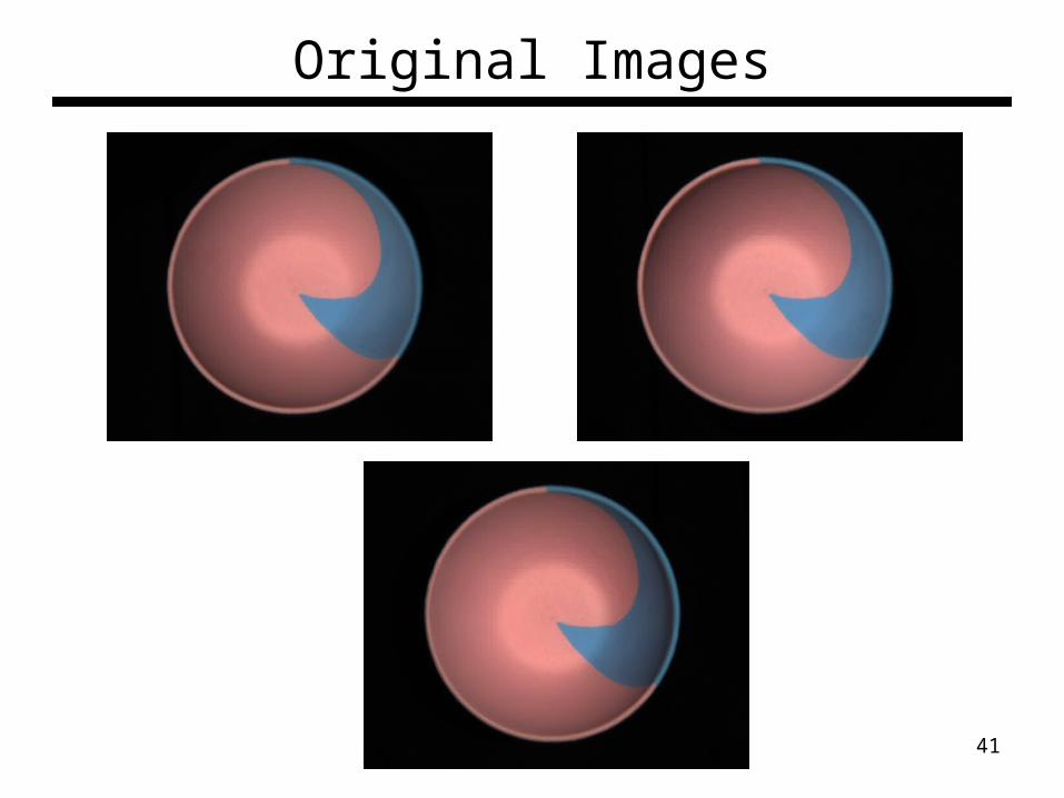
Original Images
41

Results - Shape
Shallow reconstruction (effect of interreflections)
Accurate reconstruction (after removing interreflections)42
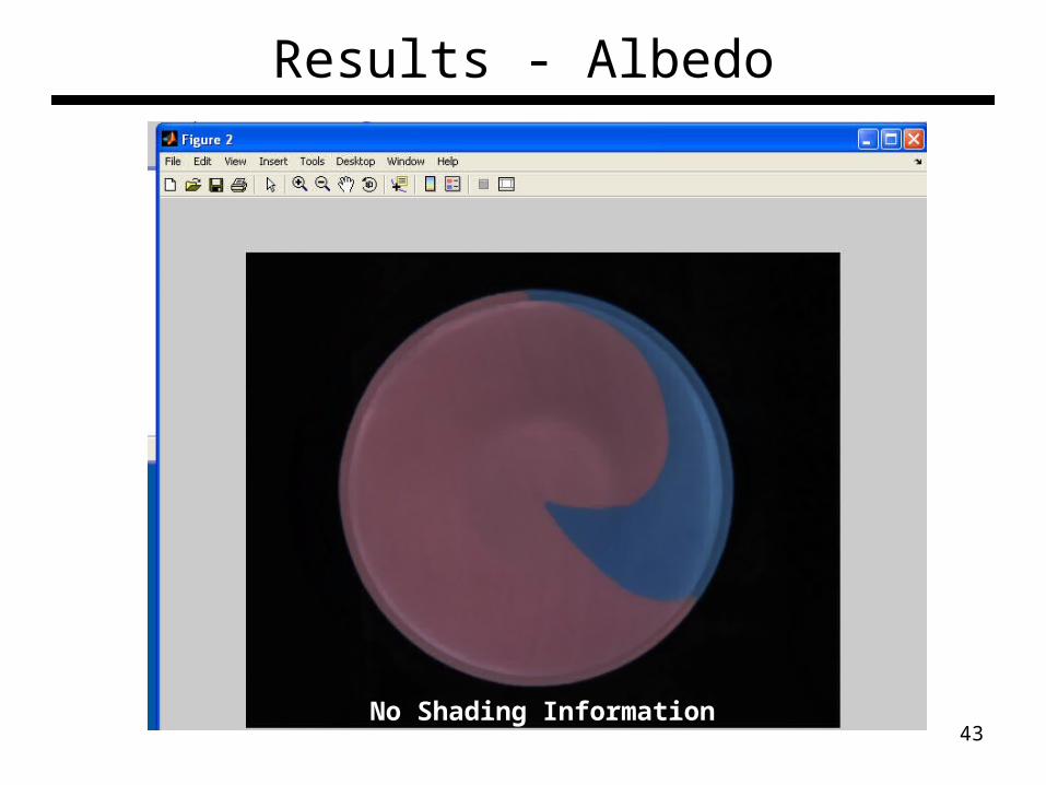
Results - Albedo
No Shading Information43

Original Images
44

Results - Shape
45
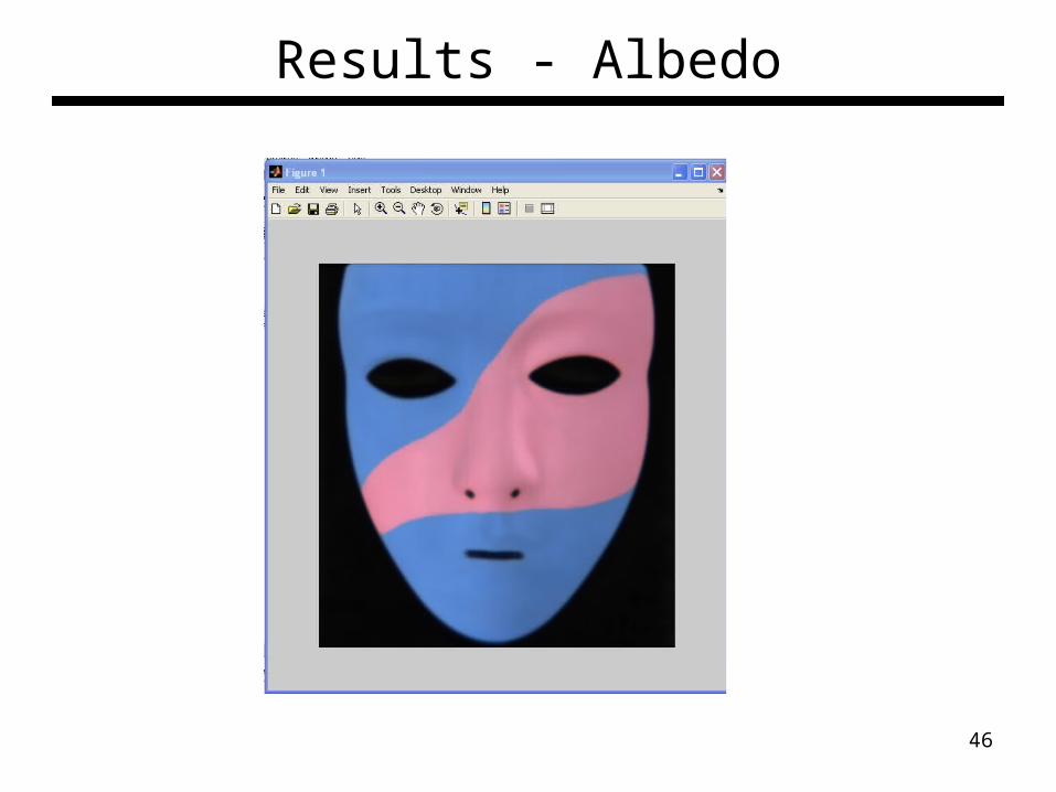
Results - Albedo
46

Results
1. Estimate light source directions2. Compute surface normals3. Compute albedo values4. Estimate depth from surface normals5. Relight the object (with original texture and uniform albedo)
47

Photometric stereo example
data from: http://www1.cs.columbia.edu/~belhumeur/pub/images/yalefacesB/readme48
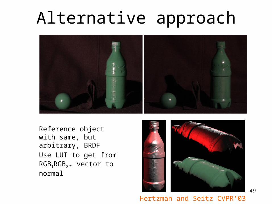
Alternative approach
Reference object with same, but arbitrary, BRDFUse LUT to get from RGB1RGB2… vector to normal
Hertzman and Seitz CVPR’0349

Photometric stereo camera• A Hand-held Photometric Stereo Camera for 3-D
Modeling, ICCV’09
50
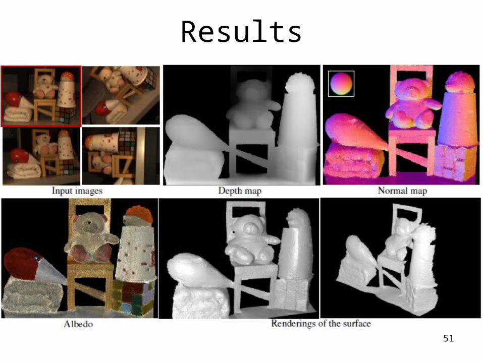
Results
51

Self-calibrating Photometric Stereo
52
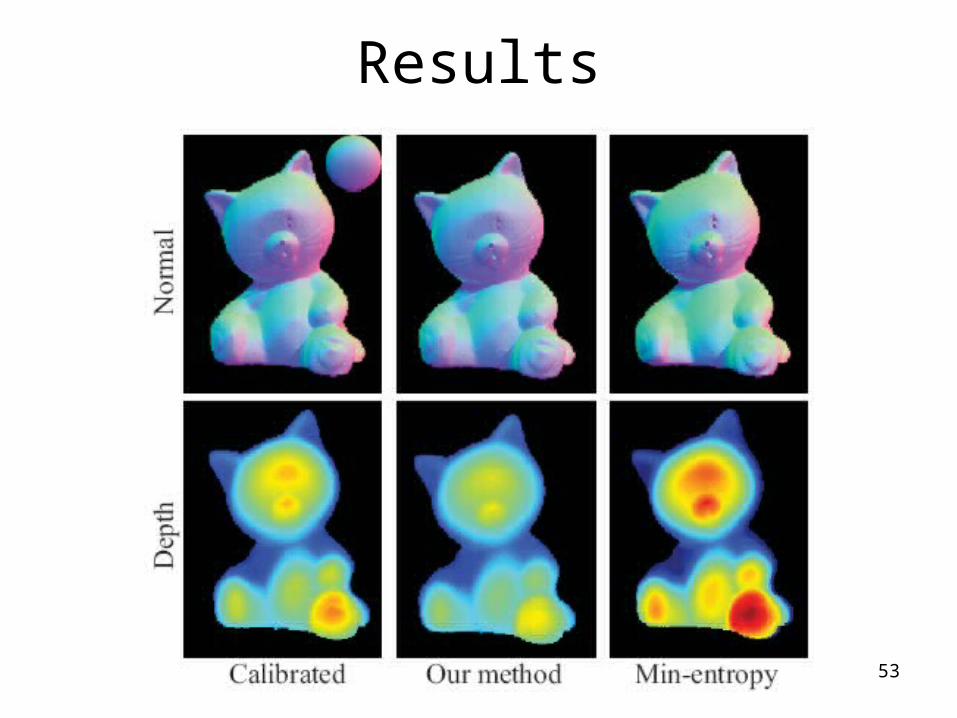
Results
53

Other applications: Shape Palette
• Painting the “normals” for surface reconstruction• A unit sphere has all normal directions• User mark-up correspondents to transfer
normals from sphere to images
54
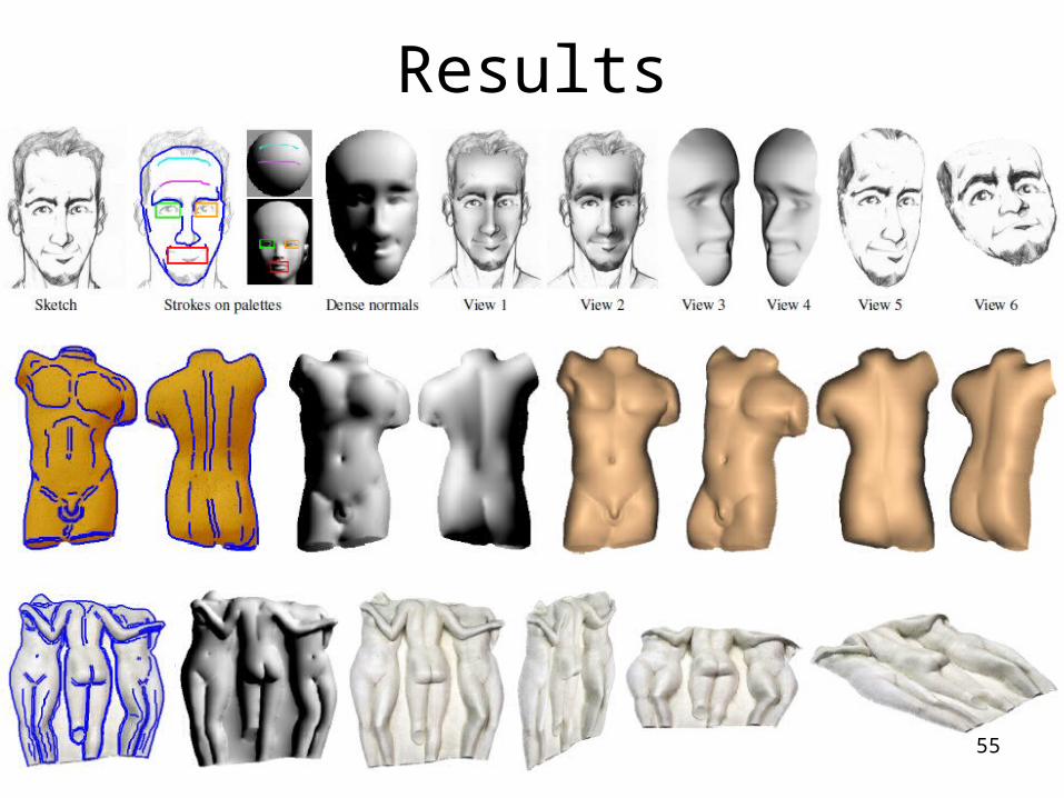
Results
55

Multi-view Photometric stereo• Combining multi-view stereo with photometric
stereo
56
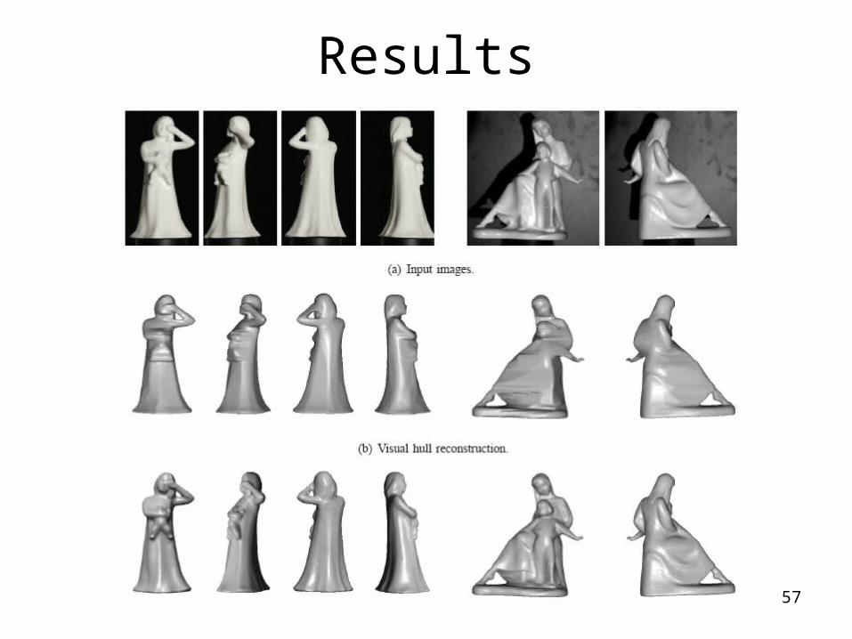
Results
57
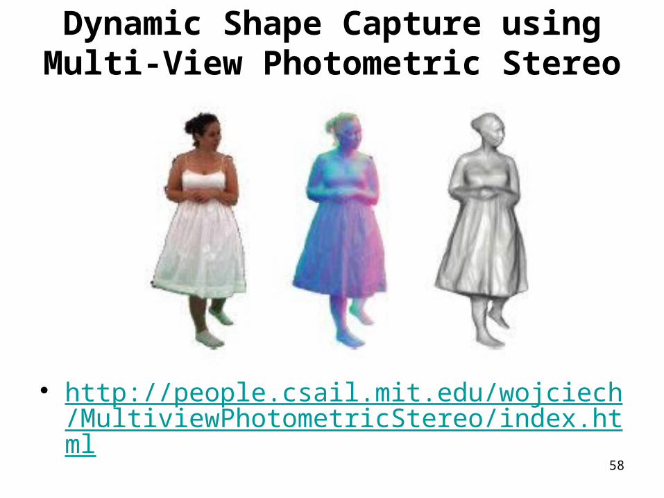
Dynamic Shape Capture using Multi-View Photometric Stereo
• http://people.csail.mit.edu/wojciech/MultiviewPhotometricStereo/index.html
58
Suggested Reading• Example-Based Photometric Stereo: Shape
Reconstruction with General, Varying BRDFs, PAMI’05• Dense Photometric Stereo: A Markov Random Field
Approach, PAMI’06• ShapePalettes: Interactive Normal Transfer via
Sketching, Siggraph’07• Non-rigid Photometric Stereo with Colored Lights,
ICCV’07• A Photometric Approach for Estimating Normals and
Tangents, Siggraph Asia’08• A Hand-held Photometric Stereo Camera for 3-D
Modeling, ICCV’09• Self-calibrating Photometric Stereo, CVPR’10
59

Summary• Radiometry
– Describe how the camera responses to the incoming lights
– Radiometry calibration, estimation of the camera response function
• Photometric stereo– Estimate normal and surface from multiple images of
same object with different lighting– We study the method for Lambertian surface– We study the method for surface reconstruction from
normals– Albedo and Normal information of a surface is very
useful and have many applications 60