radionova rf antenna module - sycom21.co.krsycom21.co.kr/images/m20050-1.pdf · 2017-10-30 · gps...
TRANSCRIPT
Antennas for Wireless M2M Applications 1
Product Specification GPS RADIONOVA M20050-1 PS-1.0
RADIONOVA Part No. M20050-1
RF Antenna Module Product Specification
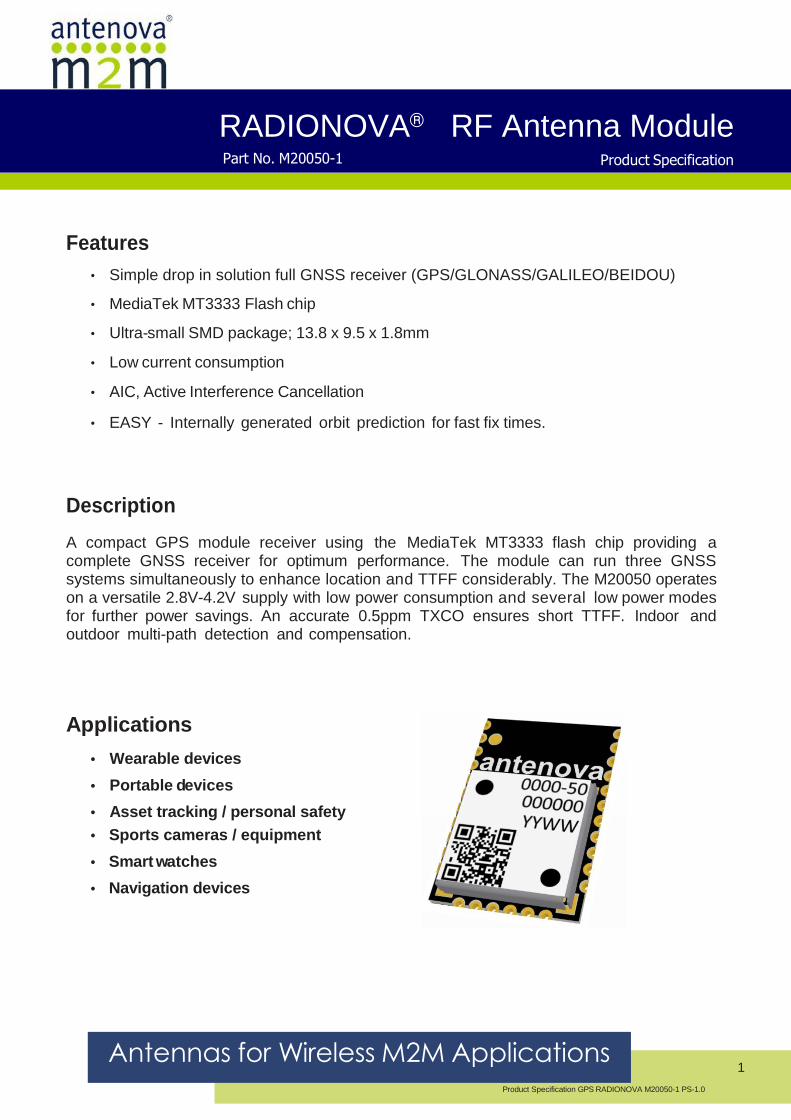
Features
• Simple drop in solution full GNSS receiver (GPS/GLONASS/GALILEO/BEIDOU)
• MediaTek MT3333 Flash chip
• Ultra-small SMD package; 13.8 x 9.5 x 1.8mm
• Low current consumption
• AIC, Active Interference Cancellation
• EASY - Internally generated orbit prediction for fast fix times.
Description
A compact GPS module receiver using the MediaTek MT3333 flash chip providing a complete GNSS receiver for optimum performance. The module can run three GNSS systems simultaneously to enhance location and TTFF considerably. The M20050 operates on a versatile 2.8V-4.2V supply with low power consumption and several low power modes for further power savings. An accurate 0.5ppm TXCO ensures short TTFF. Indoor and outdoor multi-path detection and compensation.
Applications
• Wearable devices
• Portable devices
• Asset tracking / personal safety
• Sports cameras / equipment
• Smart watches
• Navigation devices

GPS RADIONOVA® RF Antenna Module Part No. M20050-1
Antennas for Wireless M2M Applications 2
Product Specification GPS RADIONOVA M20050-1-PS-1.0
Antenova RADIONOVA
Part number
M20050-1
Functional Block Diagram
Top Side Bottom Side
Pin 1

GPS RADIONOVA® RF Antenna Module Part No. M20050-1
Antennas for Wireless M2M Applications 3
Product Specification GPS RADIONOVA M20050-1-PS-1.0
Module Specifications
Absolute Maximum Ratings
Symbol Parameter Min Max Unit
V CC Main Supply Voltage -0.3 4.3 V
V IO Supply voltage I/O ring -0.3 3.6 V
VBATT VBCKP Supply -0.3 4.3 V
RF IN Maximum RF Input Power N/A +10 dBm
T STG Storage Temperature -40 +85 °C
T A Operating Temperature -40 +85 °C
* Exposure to absolute ratings may adversely affect reliability and may cause permanent damage.
Recommended Operating Conditions
Symbol Parameter Min Typ Max Unit
V CC Main Supply Voltage 2.8 3.3 4.3 V
V BATT VBCKP Supply 2.8 3.3 4.3 V
T OP Operating Temperature -40 - +85 °C
DC Electrical Characteristics Conditions: V
CC = 3.3V, T
OP = 25 °C
Symbol Parameter Typ Unit
I CC(PK) Peak Acquisition Current 29 mA
I CC(AVG) Average Tracking Supply Current 21 mA
I CC(STBY) Standby (Sleep) Power Supply Mode <500 µA
I CC(BCKUP) Backup Mode 7 µA
RF Specifications
Conditions: V = 3.3V, T = 25°C, Freq = 1575.420MHz
Symbol Parameter Typ Unit
NF LNA LNA Noise Figure 2.0 dB
ANT RL Antenna Return Loss <-7.0 dB
ANT BW Antenna Bandwidth at -7dB return loss 65 MHz
ANT EFF Antenna Total Efficiency >57% %
ANT EFF_RHCP Antenna RHCP Efficiency >28% %

GPS RADIONOVA® RF Antenna Module Part No. M20050-1
Antennas for Wireless M2M Applications 4
Product Specification GPS RADIONOVA M20050-1-PS-1.0
Band Rejection
Frequency Standard Typ* Unit
698-798 LTE700 43 dB
824-849 Cellular CDMA 43 dB
869-894 GSM850 43 dB
880-915 GSM900 43 dB
1710-1785 GSM1800/DCS 44 dB
1850-1910 GSM1900/PCS 46 dB
1920-1980 WCDMA 46 dB
2400-2492 WLAN, BT and WiMAX 50 dB
2500-2690 LTE2600 52 dB
*Does not include antenna rejection.
Mechanical Specifications
Parameter Typ Unit
Module exterior dimensions (L x W x H) 13.8 (±0.1) x 9.5 (±0.1) x 1.8 (+0.2 / - 0.0) mm
Module support and connection Surface mounted (SMD) -
Module mass <1 g

GPS RADIONOVA® RF Antenna Module Part No. M20050-1
Antennas for Wireless M2M Applications 5
Product Specification GPS RADIONOVA M20050-1-PS-1.0
System Specifications
Communication Specification
Data Output Protocol NMEA 0183
Host Interfaces UART
Default data rate on UART 9600 default rate, modify by input command
GPS Engine
Chip MTK MT3333 FLASH Chip
Channels 210 PRN / 66 Acquisition / 22 Tracking
TCXO 0.5ppm
Accuracy
Horizontal Position Accuracy <2.5m CEP
Maximum Position Update Rate 10 Hz (Default 1Hz)
Sensitivity
Acquisition (Cold) -148dBm
Acquisition (Hot) -163dBm
Tracking -165dBm
TTFF
Hot Start <1s
Warm Start <25s (typical)
Cold Start <35s (typical)
General
Maximum Altitude <18.000 km
Maximum Speed <514 m/s
Active Interference Cancellers 12 multi tone active cancellers
ISSCC2011 award
Additional Features 1PPS Sync
EPO / EASY Orbit prediction
50% CEP, Open-Sky, 24hr Static, -130dBm, good view of the sky

GPS RADIONOVA® RF Antenna Module Part No. M20050-1
Antennas for Wireless M2M Applications 6
Product Specification GPS RADIONOVA M20050-1-PS-1.0
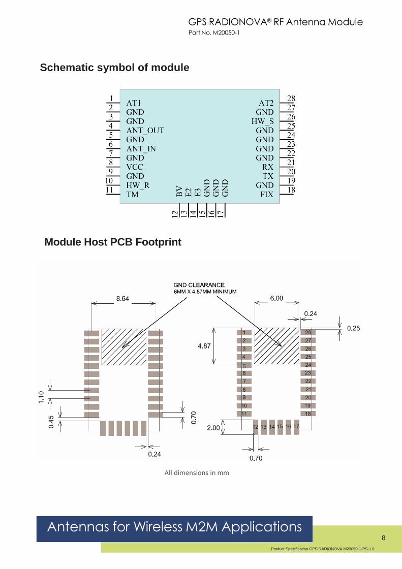
Pin out Description
Table shows the designation and function of each pin on the M20050-1 module.
Pin Designator Description
1 AT1 Tuning Left side
2 GND Ground connection
3 GND Ground connection
4 ANT_OUT RF from internal antenna to external pin (Connect to pin 6)
5 GND Ground connection
6 ANT_IN RF Input from antenna
7 GND Ground connection
8 VCC Main DC supply, +2.8V to +4.2V
9 GND Ground connection
10 HW_R System reset, active low
11 TM 1PPS Time Mark Out
12 BV Backup Voltage +2.0V to +4.2V
13 E2 Not used
14 E3 Not used
15 GND Ground connection
16 GND Ground connection
17 GND Ground connection
18 FIX Indicates once a GPS fix has been obtained.
19 GND Ground connection
20 TX UART Transmit data line
21 RX UART Receive data line
22 GND Ground connection
23 GND Ground connection
24 GND Ground connection
25 GND Ground connection
26 HW_S Used to enable standby mode. If not used leave floating.
27 GND Ground connection
28 AT2 Tuning Right Side

GPS RADIONOVA® RF Antenna Module Part No. M20050-1
Antennas for Wireless M2M Applications 7
Product Specification GPS RADIONOVA M20050-1-PS-1.0
Mechanical
L W H
Length Width Height
13.8 ±0.1 9.5 ±0.1 1.8 +0.2 / - 0.0
All dimensions in mm
GPS RADIONOVA® RF Antenna Module Part No. M20050-1
Antennas for Wireless M2M Applications 8
Product Specification GPS RADIONOVA M20050-1-PS-1.0
Schematic symbol of module
Module Host PCB Footprint
All dimensions in mm

GPS RADIONOVA® RF Antenna Module Part No. M20050-1
Antennas for Wireless M2M Applications 9
Product Specification GPS RADIONOVA M20050-1-PS-1.0
Application Schematic Example for M20050-1:
The circuit below shows a basic design for use with the UART interface and configuring the default
baud rate to 9600.
Baud Rate = 9600 (Default)
Bill of Material
Designator Value Description/Comments Quantity
C1, C2, C4, C5, C6 22pF capacitor Decoupling cap. Place close to corresponding pin 5
C3 2.2uF capacitor Decoupling cap. Place close to corresponding pin 1
L1 1.8nH Tuning Inductor for antenna 1
L2, L3 47nH Inductor Filter component 2
R1 0R Resistor Tuning Resistor for antenna 1
GPS RADIONOVA® RF Antenna Module Part No. M20050-1
Antennas for Wireless M2M Applications 10
Product Specification GPS RADIONOVA M20050-1-PS-1.0
Host Interface UART Interface
The UART converts bytes of data to and from asynchronous start -stop bit streams as binary electrical impulses. The port contains a 16-byte FIFO, and 256 bytes of URAM. The bit rates are selectable from 4800, 9600, 38400 and 115200 bps.
The IO level from the UART port are CMOS compatible, however for RS232 compatibility the use of external level shifters will be required. The hardware configuration of the port baud can be changed dynamically by the use of commands. These will be active and saved as long as the VBACKP supply is applied.
Power Supply
The M20050-1 uses two DC supply inputs, VBCKUP to power the RAM and RTC sections of the receiver, and VCC to power the digital and processing sections. VBCKUP is to be applied all the time to keep these sections alive. VCC can be removed to initiate a backup power save mode (See page 10). VBCKUP can be removed if a battery is also used at VBCKUP to maintain this supply. The supply is internally regulated for 2.8V meaning the external supply is versatile for a range of voltage levels.
TM (1PPS)
TM is a one pulse per second output from the receiver providing uses for timing purposes. The pulse width is 100ms.
HRST (Hardware Reset Pin) The External reset pin is default high by an internal 75Kohm and should be left floating if not used. To initiate a reset the pin needs to be pulled low. The module also initiates a reset if the VCC drops below the minimum 2.8V supply.

GPS RADIONOVA® RF Antenna Module Part No. M20050-1
Antennas for Wireless M2M Applications 11
Product Specification GPS RADIONOVA M20050-1-PS-1.0
Power Management The M20050-1 has three power saving modes.
• Standby mode • Back up mode • Periodic mode
Standby Mode Standby mode is a power saving mode that shuts down the RF section of the module and puts the processor into a standby mode. The RTC is kept alive and the RAM power is maintained to keep the module configuration.
The standby state can be initiated either with a hardware signal to Pin26 or by using a command.
Hardware controlled Standby:
Enable standby mode by a low state to pin 26 (HW_S). To wake the module back to full power a high state needs to be applied to pin 8. If Pin 8 is not to be used then it must be kept floating (not connected).
Standby mode command: Software on the host needs to send the “PMTK161 command through the UART interface.
Command M20050-1 standby then wakeup Current consumption (Typ)
$PMTK161,0*28 M20050-1 enters standby mode <500uA
Any byte M20050-1 wakes up from standby mode
Back up mode
To enter backup mode the VCC simply needs to be removed. Once initiated the RTC and all configuration is saved along with any ephemeris data to allow quick TTFF once the VCC is re-applied. BV needs to be applied always for backup mode to run correctly.
Periodic mode
Periodic mode is a module controlled mode that reduces current consumption by only waking the module for short periods to maintain fix data. The periodic state is user configured. Contact Antenova for more information and a user command manual.
PMTK225 setting
PMTK225, 2,3000,18000,72000
M20050-1 time off/awake
Module sleeps for 12secs, then wakes for 3secs periodically. 72000 is for a cold boot condition.
Current usage (Typ)
<500uA

GPS RADIONOVA® RF Antenna Module Part No. M20050-1
Antennas for Wireless M2M Applications 12
Product Specification GPS RADIONOVA M20050-1-PS-1.0
EPO (Extended Prediction Orbit) data service
The EPO allows the use of up to a 30-day orbit prediction that can be used to aid the module for an instant fix solution.
• A proxy server on the customer’s side to update EPO files from the MTK server daily. • Application software to access the proxy server through the internet (optional if host device
can access internet • Software on host device to send EPO data to M20050-1 module to allow instant fix by using EE
data. Please contact Antenova for more information. Requires permission from MTK to use service.
EASY (Self-Generated Orbit prediction)
The module supports EASYTM (Embedded Assisted System) is a Self-Generated Orbit Prediction feature. It provides up to 3 days GPS orbit prediction ability without the need for any host CPU porting or internet connection requirements.
EASY works as embedded software which accelerates TTFF by predicting satellite navigation messages from received ephemeris. EASY is a fully automated receiver task that is efficiently scheduled and computed in free time of every second after a GNSS navigation solution.
EASY is default off and can be enabled by a PMTK command.
AIC (Active Interference Cancellation)
The AIC feature provides effective narrow-band interference and jamming elimination. The GPS signal can be recovered from the jammed signal and allows users to obtain better navigation quality. This can be beneficial since many of today’s devices have increasing functionality with regards to transmitters with many on-board antennas.

GPS RADIONOVA® RF Antenna Module Part No. M20050-1
Antennas for Wireless M2M Applications 13
Product Specification GPS RADIONOVA M20050-1-PS-1.0
External Matching
The M20050-1 module uses matching circuit components on the host PCB to fine-tune the on-
board antenna to each specific application. This “external matching” allows compensating for the
detuning of the antenna caused by various components that can be close to the M20050-1
module in the actual application (plastic case, battery, speakers etc).
The external matching must be placed on the host PCB from pads AT1(Pad 1) and AT2 (Pad
28). A single component from each pin to GND is all that is required. This should be placed close
to the modules pads.
Schematic
In the example above AT1 only required a 0R resistor and AT2 uses a small 1.8nH inductor to
tune the antenna. Both components should be designed in as both may be required for the
intended device.
Type of Matching Components
• Capacitors:
• Use 0402, COG components
• Inductors:
• High-Q, wire wound inductors in 0402 sizes are recommended for maximum performance,
e.g. Murata LQW15 series
• Good quality multi-layer type inductors (e.g. Murata LQG15 series) can also be
used as a lower cost alternative
External Antenna Support
A low cost external circuit can be used to provide external antenna support. Please contact Antenova for
more information, and example circuit.
GPS RADIONOVA® RF Antenna Module Part No. M20050-1
Antennas for Wireless M2M Applications 14
Product Specification GPS RADIONOVA M20050-1-PS-1.0
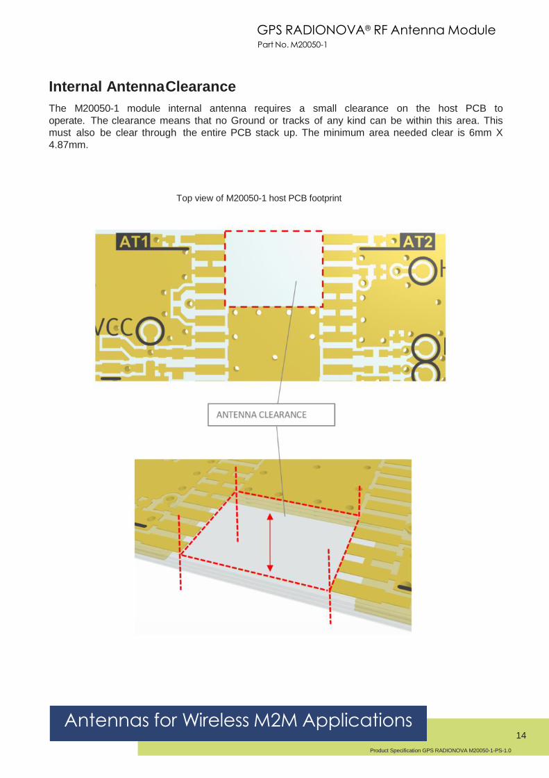
Internal Antenna Clearance
The M20050-1 module internal antenna requires a small clearance on the host PCB to
operate. The clearance means that no Ground or tracks of any kind can be within this area. This
must also be clear through the entire PCB stack up. The minimum area needed clear is 6mm X
4.87mm.
Top view of M20050-1 host PCB footprint

GPS RADIONOVA® RF Antenna Module Part No. M20050-1
Antennas for Wireless M2M Applications 15
Product Specification GPS RADIONOVA M20050-1-PS-1.0
Typical Antenna Matching Results
Typical antenna matching as seen by ANT_IN (Pin 3) is shown in the following plot. The matching
bandwidth at -7dB is typically 65MHz. Measured on M20050-EVB-1 test board.

GPS RADIONOVA® RF Antenna Module Part No. M20050-1
Antennas for Wireless M2M Applications 16
Product Specification GPS RADIONOVA M20050-1-PS-1.0
Front-end Rejection
The figure below shows the rejection for the input SAW filter before the RF input, including the effect of
pads, tracks, and decoupling. The plot can be useful to calculate the isolation required from adjacent
transmitters
to avoid the saturation of the LNA.
Input SAW Rejection – Wideband
Input SAW Rejection - Narrowband
1200 1300 1400 1500 1600 1700 1800 1900 2000-80
-70
-60
-50
-40
-30
-20
-10
0
10
[MHz]
[dB] Atyune
1 2
0 600 1200 1800 2400 3000 3600 4200 4800 5400 6000-80
-70
-60
-50
-40
-30
-20
-10
0
10
[MHz]
[dB] Atyune
12

GPS RADIONOVA® RF Antenna Module Part No. M20050-1
Antennas for Wireless M2M Applications 17
Product Specification GPS RADIONOVA M20050-1-PS-1.0
Module Placement Guidelines
Due to the internal antenna, care must be taken when defining the placement of the module on the
host PCB. Here are some guidelines that should be used when deciding the position of the module.
• The module top edge must be placed almost level with the edge of the host PCB
• The edge of the host PCB that the module is to be placed at must be a minimum of 40mm in length.
• The central placement of the module is advised. However, an offset placement is also possible.
• For an offset closer to the PCB edge to the right side of the module, a minimum of 10mm
distance is required to the edge of the host PCB.

GPS RADIONOVA® RF Antenna Module Part No. M20050-1
Antennas for Wireless M2M Applications 18
Product Specification GPS RADIONOVA M20050-1-PS-1.0
• The antenna uses the host PCB ground to effectively radiate. As such, a GND plane must
be placed on the host PCB on at least one layer.
• In the example below, the only area void of GND is the antenna keep-out area. The solder mask is removed to make the copper visible.
• An ideal stack-up for a host PCB would be to use the top and bottom layers as GND
planes, while using the internal layers for any signal and power planes. This not only
helps the GPS antenna to perform effectively, but also helps to reduce any potential
noise issues that can be associated with mixed signal PCB’s.
• An example below shows a 4-layer host PCB, GND flooding all available space not used by
signals or components.
Please contact Antenova M2M for advice on placement.

GPS RADIONOVA® RF Antenna Module Part No. M20050-1
Antennas for Wireless M2M Applications 19
Product Specification GPS RADIONOVA M20050-1-PS-1.0
Evaluation Kit
The EVK is a single PCB that contains the module and required components to run on a PC via a USB cable and Antenova software. Evaluation kits are available on request. Please contact Antenova for more information.
M20050-EVB-1
Top Side Bottom Side

GPS RADIONOVA® RF Antenna Module Part No. M20050-1
Antennas for Wireless M2M Applications 20
Product Specification GPS RADIONOVA M20050-1-PS-1.0
Reflow Soldering
Placement
Typical placement systems used for any BGA/LGA package are acceptable. Recommended nozzle
diameter for placement: 5mm.
Soldering Paste
Use of “No Clean” soldering paste is strongly recommended, as it does not require cleaning
after the soldering process has taken place. An example of suitable soldering paste is Alpha
OM350.
Soldering
The recommended soldering profile for M20050-1 is shown below. However, it is the responsibility
of the Contract Manufacturer to determine the exact reflow profile used, taking into consideration
the parameters of the host PCB, solder paste used, etc.
Profile Feature Pb-Free Solder
Pre-Heat
Temperature (Ts ) Min 130°C
Temperature (Ts ) Max 220°C
Time (ts ) <150s
Reflow
Liquidus Temperature - (Tl ) 220°C
Time (tl ) 45-90s
Peak Package Body Temperature (Tp) 245°C
Time within 5°C of peak temp (tp) 30s
Average Ramp up rate - Ts(max) to (Tp) 3°C/s
Ramp Down Rate 6°C/s max
Example Reflow profile
The Pb Free Process-Package Peak Reflow Temperature is 260ºC.
Exceeding the maximum soldering temperature could permanently damage the module.
GPS RADIONOVA® RF Antenna Module Part No. M20050-1
Antennas for Wireless M2M Applications 21
Product Specification GPS RADIONOVA M20050-1-PS-1.0
Multiple Soldering
The M20050-1 module can be submitted up to 2 reflow soldering processes.
Upside-down soldering is acceptable but it is recommended that the Contract Manufacturer
qualify the process before mass production. The second reflow must take place within the
recommended floor life limit (MSL3). Please contact Antenova for further information.
Hand Soldering
Hand-soldering and rework of the M20050-1 module is acceptable, however care must be taken to avoid
short circuits due to the small size of the module pads.
GPS RADIONOVA® RF Antenna Module Part No. M20050-1
Antennas for Wireless M2M Applications 22
Product Specification GPS RADIONOVA M20050-1-PS-1.0
Quality and Environmental Specifications
Test Standard Parameters
PCB Inspection IPC-6012B, Class 2. Qualification and
Performance Specification for Rigid Printed
Boards - Jan 2007
Assembly
Inspection
IPC-A-610-D, Class 2 “Acceptability of
electronic assemblies”
Temperature
Range
ETSI EN 300 019-2-7 specification T 7.3 -30 °C, +25 °C, +85 °C, operating
Damp Heat ETSI EN 300 019-2-7 specification T 7.3 +70 °C, 80% RH, 96 hrs, non-
operating
Thermal Shock ETSI EN 300 019-2-7 specification T 7.3 E -40 °C ... +85 °C, 200 cycles
Vibration ISO16750-3 Random vibration, 10~1000Hz,
27.8m/s2, 8hrs/axis, X, Y, Z 8hrs for
each 3 axis non-operating
Shock ISO16750-3 Half-sinusoidal 50g, 6ms, 10time/face,
±X, ±Y and ±Z non-operating
Free Fall ISO16750-3 1m height, 2 drops on opposite side
ESD Sensitivity JEDEC, JESD22-A114 ESD Sensitivity
Testing Human Body Model (HBM). Class 2
JEDEC, JESD22-A115 ESD Sensitivity
Testing Machine Model (MM), Class B
+2000V - Human hand assembly
+200V - Machine automatic final
assembly
Shear IEC 60068-2-21, Test Ue3: Shear Force of 5N applied to the side of the
PCB
Moisture/Reflow
Sensitivity
IPC/JEDEC J-STD-020D.1 MSL3
Storage (Dry
Pack)
IPC/JEDEC J-STD-033C MSL3
Solderability EN/IEC 60068-2-58 Test Td More than 90% of the electrode
should be covered by solder. Solder
temperature 245 °C ± 5 °C
Moisture Sensitivity
Antenova ships all devices dry packed in tape on reel with desiccant and moisture level indicator
sealed in an airtight package. If on receiving the goods the moisture indicator is pink in colour or a
puncture of the airtight seal packaging is observed, then follow J-STD-033 “Handling and Use of
Moisture/Reflow Sensitive Surface Mount Devices”.
Storage (Out of Bag)
The M20050-1 modules meet MSL Level 3 of the JEDEC specification J-STD-020D - 168 hours
Floor Life (out of bag) ≤30 °C/60% RH. If the stated floor life expires prior to reflow process
then follow J-STD-033 “Handling and Use of Moisture/Reflow Sensitive Surface Mount Devices”.
GPS RADIONOVA® RF Antenna Module Part No. M20050-1
Antennas for Wireless M2M Applications 23
Product Specification GPS RADIONOVA M20050-1-PS-1.0
Hazardous material regulation conformance
The RF antenna module meets RoHS requirements.
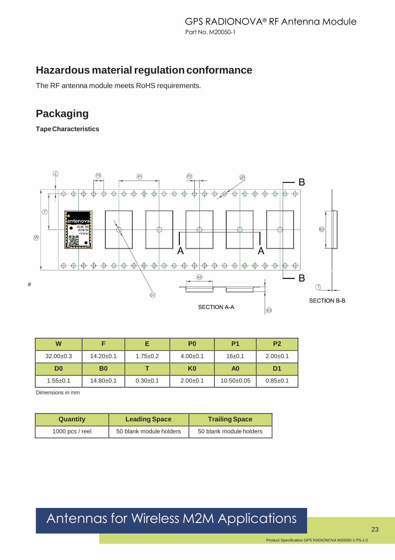
Packaging
Tape Characteristics
#
W F E P0 P1 P2
32.00±0.3 14.20±0.1 1.75±0.2 4.00±0.1 16±0.1 2.00±0.1
D0 B0 T K0 A0 D1
1.55±0.1 14.80±0.1 0.30±0.1 2.00±0.1 10.50±0.05 0.85±0.1
Dimensions in mm
Quantity Leading Space Trailing Space
1000 pcs / reel 50 blank module holders 50 blank module holders

GPS RADIONOVA® RF Antenna Module Part No. M20050-1
Antennas for Wireless M2M Applications 24
Product Specification GPS RADIONOVA M20050-1-PS-1.0
Reel Dimensions
Width
(W)
Reel Diameter
(D)
Hub Diameter
(H)
Shaft Diameter
(C)
32.0mm 330.0±2mm 100.0mm 13.0+0.2/-0.0mm

Corporate Headquarters
Antenova Ltd.
2nd
Floor, Titan Court,
3 Bishop Square,
Hatfield, AL10 9NA
UK
Tel: +44 (0) 1223 810600
Email: [email protected]
USA Headquarters
Antenova USA
100 Brush Creek Road, Suite 103, Santa Rosa, CA 95404 USA
Tel: +1 (707) 890 5202
Email: [email protected]
Asia Headquarters
Antenova Asia Ltd.
4F, No. 324, Sec. 1, Nei-Hu Road
Nei-Hu District
Taipei 11493
Taiwan, ROC
Tel: +886 (0) 2 8797 8630
Fax: +886 (0) 2 8797 6890
Email: [email protected]
Copyright® Antenova Ltd. All Rights Reserved. Antenova®, Antenova M2M, RADIONOVA®
and the Antenova and Antenova M2M logos are trademarks and/or registered trademarks of
Antenova Ltd. Any other names and/or trademarks belong to their respective companies.
The materials provided herein are believed to be reliable and correct at the time of print.
Antenova does not warrant the accuracy or completeness of the information, text, graphics or
other items contained within these information. Antenova further assumes no responsibility for
the use of this information, and all such information shall be entirely at the user’s risk.
Antennas for Wireless M2M Applications
25
Product Specification GPS RADIONOVA M20050-1 PS 1.0 Released October 2017