rail accident report - gov.uk€¦ · rail accident report ... the permitted speed for trains on...
TRANSCRIPT

Report 20/2014October 2014
Rail Accident Report
Freight train derailment near Gloucester15 October 2013

This investigation was carried out in accordance with:
l the Railway Safety Directive 2004/49/EC;l the Railways and Transport Safety Act 2003; and l the Railways (Accident Investigation and Reporting) Regulations 2005.
© Crown copyright 2014 You may re-use this document/publication (not including departmental or agency logos) free of charge in any format or medium. You must re-use it accurately and not in a misleading context. The material must be acknowledged as Crown copyright and you must give the title of the source publication. Where we have identified any third party copyright material you will need to obtain permission from the copyright holders concerned. This document/publication is also available at www.raib.gov.uk.
Any enquiries about this publication should be sent to:
RAIB Email: [email protected] Wharf Telephone: 01332 253300Stores Road Fax: 01332 253301 Derby UK Website: www.raib.gov.ukDE21 4BA
This report is published by the Rail Accident Investigation Branch, Department for Transport.

Report 20/2014Gloucester
3 October 2014
Freight train derailment near Gloucester15 October 2013
Contents
Summary 5Introduction 6
Preface 6Key definitions 6
The accident 7Summary of the accident 7Context 9Events preceding the accident 11Events during the accident 12Events following the accident 13
The investigation 15Sources of evidence 15
Key facts and analysis 16Background information (track) 16Timeline (track) 20Background information (IDA wagon) 21Timeline (IDA wagon) 23Identification of the immediate cause 24Identification of causal factors 26Factors affecting the severity of consequences 58Observations 61Previous occurrences of a similar character 64
Summary of conclusions 65Immediate cause 65Causal factors 65Underlying factors 66Additional observations 66
Previous RAIB recommendations relevant to this investigation 67Recommendations that are currently being implemented 67

Report 20/2014Gloucester
4 October 2014
Actions reported as already taken or in progress relevant to this report 69Actions reported that address factors which otherwise would have resulted in a RAIB recommendation 69Other reported actions 70
Learning points 72Recommendations 73Appendices 76
Appendix A - Glossary of abbreviations and acronyms 76Appendix B - Glossary of terms 77

Report 20/2014Gloucester
5 October 2014
Summary
At about 20:15 hrs on 15 October 2013, a freight train operated by Direct Rail Services, which was carrying containers, derailed about 4 miles (6.4 km) south west of Gloucester station on the railway line from Newport via Lydney. It was travelling at 69 mph (111 km/h) when the rear wheelset of the last wagon in the train derailed on track with regularly spaced dips in both rails, a phenomenon known as cyclic top. The train continued to Gloucester station where it was stopped by the signaller, who had become aware of a possible problem with the train through damage to the signalling system. By the time the train stopped, the rear wagon was severely damaged, the empty container it was carrying had fallen off, and there was damage to four miles of track, signalling cables, four level crossings and two bridges.The immediate cause of the accident was a cyclic top track defect which caused a wagon that was susceptible to this type of track defect to derail. The dips in the track had formed due to water flowing underneath the track and although the local Network Rail track maintenance team had identified the cyclic top track defect, the repairs it carried out were ineffective. The severity of the dips required immediate action by Network Rail, including the imposition of a speed restriction for the trains passing over it, but no such restriction had been put in place. Speed restrictions had repeatedly been imposed since December 2011 but were removed each time repair work was completed; on each occasion, such work subsequently proved to be ineffective. The type of wagon that derailed was found to be susceptible to wheel unloading when responding to these dips in the track, especially when loaded with the type of empty container it was carrying. This susceptibility was not identified when the wagon was tested or approved for use on Network Rail’s infrastructure.The RAIB also observes: the local Network Rail track maintenance team had a shortfall in its manpower resources; and design guidance for the distance between the wheelsets on two-axle wagons could also be applied to the distance between the centres of the bogies on bogie wagons.The RAIB has made seven recommendations. Four are directed to Network Rail and cover reviewing the drainage in the area where the train derailed, revising processes for managing emergency speed restrictions for cyclic top track defects, providing track maintenance staff with a way of measuring cyclic top after completing repairs, and investigating how cyclic top on steel sleeper track can be effectively repaired. Two are directed to RSSB and cover reviewing how a vehicle’s response to cyclic top is assessed and amending guidance on the design of freight wagons. One is directed to Direct Rail Services and covers mitigating the susceptibility of this type of wagon to cyclic top.
Sum
mar
y

Report 20/2014Gloucester
6 October 2014
Introduction
Preface1 The purpose of a Rail Accident Investigation Branch (RAIB) investigation is to
improve railway safety by preventing future railway accidents or by mitigating their consequences. It is not the purpose of such an investigation to establish blame or liability.
2 Accordingly, it is inappropriate that RAIB reports should be used to assign fault or blame, or determine liability, since neither the investigation nor the reporting process has been undertaken for that purpose.
3 The RAIB’s investigation (including its scope, methods, conclusions and recommendations) is independent of all other investigations, including those carried out by the safety authority or railway industry.
Key definitions4 All dimensions in this report are given in metric units, except speed and location
which are given in imperial units, in accordance with normal railway practice. Where appropriate the equivalent metric value is also given.
5 The report contains abbreviations and technical terms (shown in italics the first time they appear in the report). These are explained in appendices A and B.
Introduction

Report 20/2014Gloucester
7 October 2014
© Crown Copyright. All rights reserved. Department for Transport 100039241. RAIB 2014
Location of accident
The accident
Summary of the accident 6 At about 20:15 hrs on 15 October 2013, a freight train carrying containers derailed
about 4 miles (6.4 km) south west of Gloucester station on the railway line from Newport via Lydney (figure 1). It was travelling at 69 mph (111 km/h) when the rear wheelset of the last wagon in the train derailed on track with regularly spaced dips in both rails, a phenomenon known as cyclic top.
Figure 1: Extract from Ordnance Survey map showing the location of the accident
7 The train driver was unaware of the derailment and the train continued with one wheelset derailed for a distance of around 3.8 miles (6.1 km) until, at Gloucester West Junction (figure 2), the derailed wagon collided with a set of facing points while travelling at 22 mph (35 km/h). Here both wheelsets were torn from the rear bogie and the empty container on the rear of this wagon was thrown off into the cess (figure 3).
The
acci
dent

Report 20/2014Gloucester
8 October 2014
Gloucester114 miles 04 chains
Gloucester West Junction
114 miles 40 chains
Over Junction115 miles 43 chains
Keens level crossing*116 miles 03 chains
Footpath crossing117 miles 41 chains
Pooles level crossing*116 miles 46 chains
Lower Barn level crossing*118 miles 17 chains
Point of derailment118 miles 46 chains
on up main line
Direction of travel
Stopping point for rear wagon
114 miles 20 chains
Not to scale* Level crossing where the barriers or gates are operated by the user
Direction of travel
Figure 2: Track layout from the point of derailment through to the train’s stopping point
Figure 3: The debris and dislodged container at Gloucester West Junction
8 As the train continued towards Gloucester, it caused further damage to the track and wagon, damaging two bridges and throwing debris onto a road below. As the train entered Gloucester station, the driver saw the next signal was unexpectedly displaying a red aspect and he brought the train to a stand in response. At the same time, he received an emergency call over the radio system in the cab, calling for all trains in the Gloucester area to stop. The signaller working on the signaller’s panel at Gloucester signal box had become aware of a possible problem with the train through damage to the signalling system and had taken action to stop it. The train had run derailed for about 5 minutes 30 seconds, covering a distance of 4.1 miles (6.6 km).
The accident

Report 20/2014Gloucester
9 October 2014
Direction of travel
Up main line Down main line
Point of derailment
9 No one was hurt in the accident and there were no other trains passing at the time. The railway line remained closed until the early hours of 19 October for recovery of the derailed wagon and its container, temporary repairs to the track and repairs to the damaged infrastructure. The line was reopened with a 30 mph (48 km/h) speed restriction from the point of derailment to Gloucester station.
ContextLocation10 The derailment occurred on the up main line between Lydney and Gloucester, at
118 miles and 46.64 chains (from a zero reference at London Paddington station), which is part of Network Rail’s Western Route.
11 At this location, the two track railway comprises the up main and down main lines (figure 4). The permitted speed for trains on both lines is 90 mph (145 km/h), although the maximum speed for the train that derailed was 75 mph (121 km/h). The derailment happened in a cutting, where the track is straight and on a gradient of about 1 in 370 (0.27%), rising in the train’s direction of travel.
Figure 4: Location of the derailment
12 The track on the up main line consists of continuous welded rail on steel sleepers. Signalling in the area is by the track circuit block system with three aspect colour light signals, and is controlled from the Gloucester signal box.
The
acci
dent

Report 20/2014Gloucester
10 October 2014
Organisations involved13 Network Rail owns, operates and maintains the infrastructure, including the track
where the derailment occurred. 14 The freight train was operated by Direct Rail Services, which also owns the
wagon and employs the driver. W H Davis manufactured the wagon and Wabtec supplied the wagon’s bogies and wheelsets. Network Rail Vehicle Conformance Group (now called Network Certification Body) and Lloyd’s Register Rail carried out the approval work for the wagon to operate on Network Rail’s infrastructure.
15 All of these organisations freely co-operated with the investigation.Train involved16 The freight train that derailed was the 18:58 hrs service from Wentloog, near
Cardiff, to Daventry (reporting number 4M36). It consisted of a class 66 diesel-electric locomotive, 66421, hauling 14 twin-set container flat wagons. Each twin-set wagon comprises two semi-permanently coupled vehicles, with a rigid connector between them. In train 4M36, 9 twin-sets were type IDA wagons (18 vehicles) and 5 twin-sets were type IKA wagons (10 vehicles), giving a total of 28 vehicles. The vehicle that derailed was the rear vehicle of an IDA wagon (figure 5) and the last vehicle in the train.
Figure 5: An IDA wagon (image courtesy of W H Davis)
The accident

Report 20/2014Gloucester
11 October 2014
17 All the vehicles were loaded with 45 foot (13.7 metre) long, 8 foot 6 inch (2.6 metre) high, curtain-sided containers which were either empty or partially loaded. The leading vehicle of the wagon at the rear of the train was carrying a partially loaded container weighing 10.36 tonnes and the trailing vehicle was carrying an empty container weighing 5.99 tonnes. The containers were retained on the IDA wagons by fixed spigots of standard International Union of Railways (UIC) design1.
18 No trains passed on the down main line while train 4M36 ran derailed. The only other train in the vicinity was train 1V15, a passenger train from Nottingham to Cardiff, which arrived at Gloucester station from the opposite direction very shortly after train 4M36 was brought to a stand. It stopped alongside the front of train 4M36.
Staff involved19 The driver signed on for duty at Daventry earlier that day and travelled to
Wentloog, from where he was due to drive train 4M36 to Daventry. 20 Staff based at Network Rail’s Gloucester maintenance depot were responsible
for maintaining the track where the derailment happened. The Section Manager had worked for 39 years on track maintenance in the Gloucester area, including the last 9 years as Section Manager. The Track Maintenance Engineer for Gloucester had 22 years of experience working on track maintenance, including 4 years in this post.
21 Staff working for Network Rail Vehicle Conformance Group were responsible for carrying out the approval work for the prototype IDA wagon and first batch of IDA wagons that entered service. The assessor had over 35 years of experience as a railway engineer and the certifier over 38 years of experience, including 13 on vehicle approvals. Staff working for Lloyd’s Register Rail, some of whom had over 15 years of experience on vehicle approvals, were responsible for carrying out the approval work for the second batch of IDA wagons that entered service.
External circumstances22 It was dark at the time of the accident. The local weather conditions were dry,
with a temperature of about 7°C (this is based on an assessment of records at the nearest weather station 3.8 miles (6.1 km) away). There were no external circumstances which directly affected the accident although water, from rainfall over a long period of time, had affected the condition of the track (paragraphs 68 to 76).
Events preceding the accident23 The wagons that formed train 4M36 had earlier travelled from Daventry to
Wentloog carrying laden 45 foot curtain-sided containers. At Wentloog, these containers were unloaded and replaced with empty or partially laden containers.
1 Further information about spigots can be found in RAIB report 12/2009, Detachment of containers from freight wagons near Cheddington and Hardendale, 1 March 2008.
The
acci
dent

Report 20/2014Gloucester
12 October 2014
Direction of travel
24 When the driver arrived at Wentloog, he moved the locomotive so it could be coupled onto the front of the train. After its pre-departure checks2 were completed, the train departed the sidings at Wentloog at 19:20 hrs, 22 minutes late.
25 At 19:43 hrs, train 4M36 passed Severn Tunnel Junction and took the line towards Gloucester via Lydney. The train was now on time due to a combination of running under green signals and allowances in its timetable. At 20:06 hrs it passed Awre Junction, running 5 minutes early. At 20:15 hrs, it arrived at 118 miles 56 chains on the up main line, which is where the cyclic top started and continued through to 118 miles 43 chains (a distance of 286 yards (262 metres)).
Events during the accident 26 The train passed over the section of track containing cyclic top while travelling at
69 mph (111 km/h). The locomotive and following 27 vehicles did not derail but the rear wheelset of the 28th vehicle, at the rear of the train, lifted clear of the rail. Marks found on the head of the six foot rail show the flange of its right-hand wheel landed on top of this rail at 118 miles 46.64 chains (figure 6).
Figure 6: The flange mark on the head of the six foot rail
2 The pre-departure check is a physical examination of the train to ensure that the train is safe to depart and includes checks for the brakes, couplings and loads of the wagons. Full details are provided in Working Manual for Rail Staff Freight Train Operations, Section C - Principles of Safe Freight Train Operation, reference GO/RT3056/C.
The accident

Report 20/2014Gloucester
13 October 2014
27 The flange ran along the head of the rail for 3.75 metres before the wheelset derailed to the right. At this point the left-hand wheel derailed into the four foot.
28 The train continued with the rear wheelset running derailed for the next 3 miles. There was no indication to the driver of a problem with the train as there was no damage to the train’s brake pipe so its brakes did not unexpectedly apply (the braking system of rail vehicles is such that if the air pressure in the brake pipe reduces, the train’s brakes will apply). The rear wheelset was kept roughly in line by the leading wheelset of the rear bogie and ran on top of the clips that hold the rail in place (evidenced by damage to the clips and sleepers). The derailed wheelset ran over four level crossings, damaging the wooden decking (figure 7). As the train approached Gloucester, it began to slow down as the permitted speed on the up main line reduces to 60 mph (97 km/h) at 115 miles 70 chains.
Figure 7: Examples of the damage caused by the derailed wheelset to level crossing surfaces
Events following the accident 29 After about 3 miles (4.8 km), while travelling at 45 mph (72 km/h), the derailed
wheelset struck a check rail at Over Junction which is located at 115 miles 43 chains. No other wheels derailed as a result of this impact and the train continued for just over a mile to Gloucester West Junction, which is located at 114 miles 40 chains. Here, the permitted speed on the up main lines further reduces to 40 mph (64 km/h) and while travelling at 22 mph (35 km/h), the derailed wheelset again struck a check rail. This time the impact caused both wheelsets from the rear bogie and various suspension components to be ejected. The impact also dislodged the container on the rear vehicle, which landed in the cess at the top of an embankment (figure 3).
30 The train travelled for a further 0.25 miles (0.4 km) before stopping. During this time, the derailed vehicle collided with Worcester Road bridge causing both wheelsets on its leading bogie to derail and debris to fall onto the road below. The debris included a suspension spring3 from the derailed vehicle that landed on top of an unoccupied parked car. The derailed vehicle also collided with London Road bridge just as the train stopped. By the time the train stopped, the rear vehicle was severely damaged (figure 8) although the brake pipe remained intact so there was no automatic application of the train’s brakes.
3 The suspension spring weighed either 3.5 kg or 6.0 kg.
The
acci
dent
Report 20/2014Gloucester
14 October 2014
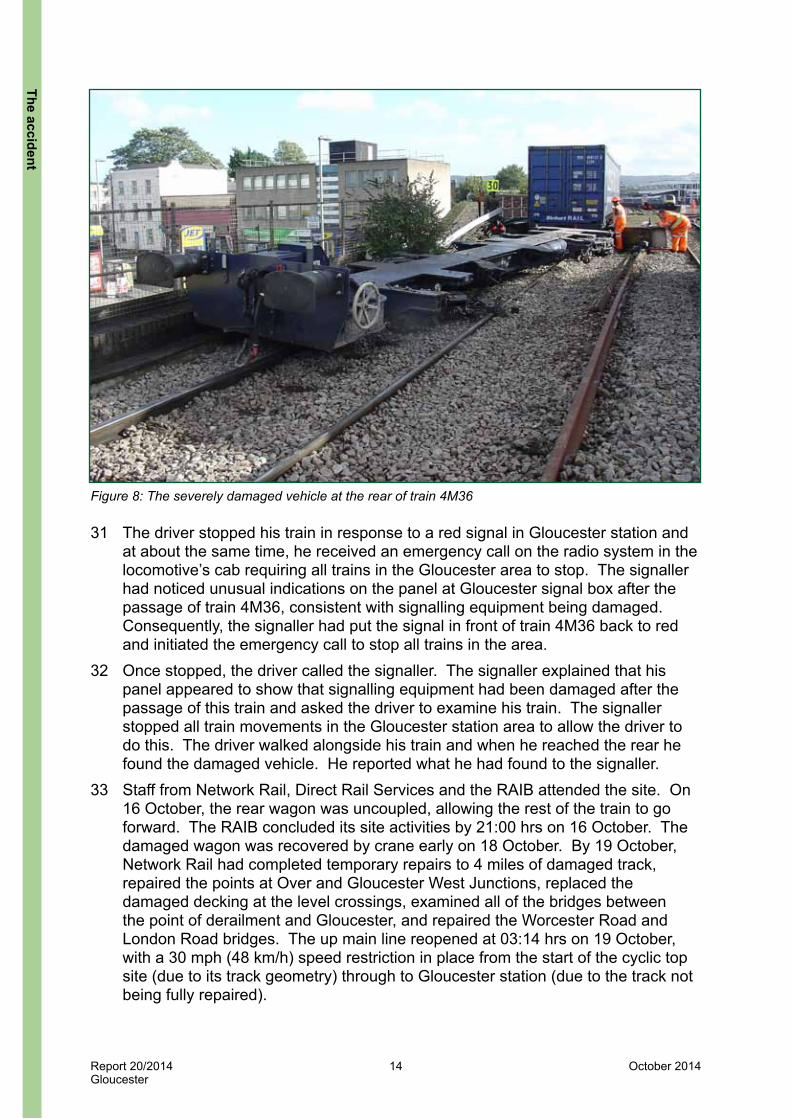
Figure 8: The severely damaged vehicle at the rear of train 4M36
31 The driver stopped his train in response to a red signal in Gloucester station and at about the same time, he received an emergency call on the radio system in the locomotive’s cab requiring all trains in the Gloucester area to stop. The signaller had noticed unusual indications on the panel at Gloucester signal box after the passage of train 4M36, consistent with signalling equipment being damaged. Consequently, the signaller had put the signal in front of train 4M36 back to red and initiated the emergency call to stop all trains in the area.
32 Once stopped, the driver called the signaller. The signaller explained that his panel appeared to show that signalling equipment had been damaged after the passage of this train and asked the driver to examine his train. The signaller stopped all train movements in the Gloucester station area to allow the driver to do this. The driver walked alongside his train and when he reached the rear he found the damaged vehicle. He reported what he had found to the signaller.
33 Staff from Network Rail, Direct Rail Services and the RAIB attended the site. On 16 October, the rear wagon was uncoupled, allowing the rest of the train to go forward. The RAIB concluded its site activities by 21:00 hrs on 16 October. The damaged wagon was recovered by crane early on 18 October. By 19 October, Network Rail had completed temporary repairs to 4 miles of damaged track, repaired the points at Over and Gloucester West Junctions, replaced the damaged decking at the level crossings, examined all of the bridges between the point of derailment and Gloucester, and repaired the Worcester Road and London Road bridges. The up main line reopened at 03:14 hrs on 19 October, with a 30 mph (48 km/h) speed restriction in place from the start of the cyclic top site (due to its track geometry) through to Gloucester station (due to the track not being fully repaired).
The accident

Report 20/2014Gloucester
15 October 2014
The investigation
Sources of evidence34 The following sources of evidence were used:
l witness statements;l the train’s on-train data recorder (OTDR) data;l site photographs, surveys and measurements;l track geometry recording data and ground penetrating radar data recorded by
Network Rail’s infrastructure measuring trains;l Network Rail’s records for track inspection and maintenance activities;l information related to Network Rail’s track renewals carried out in 2002 and
2014;l Network Rail documents for examinations of cuttings;l data recorded by Network Rail’s WheelChex system;l Network Rail’s control logs;l information for the wagon that derailed including its pre-delivery inspection
record and what load it was carrying on 15 October;l design information for the IDA wagon including its dimensions and suspension
components;l the vehicle approval records for the IDA wagon including static and ride
performance test reports;l a computer simulation commissioned by the RAIB which enabled analysis of the
interaction between the train and the track;l weather reports from a nearby weather station;l Network Rail company standards, Railway Group Standards, Technical
Specifications for Interoperability (TSIs) and British standards; and l a review of previous RAIB investigations that had relevance to this accident.
The
inve
stig
atio
n

Report 20/2014Gloucester
16 October 2014
Key facts and analysis
Background information (track)Track inspection regime35 The up main line where the derailment happened was classified by Network Rail
as a category 2 track. This category, which is based on the permitted speed and tonnage passing over the line (ie the number of trains and their weight), is used to define the track inspection regime. In accordance with Network Rail’s standards for track maintenance, NR/L2/TRK/001/mod02 ‘Track Inspection’ and NR/L2/TRK/001/mod11 ‘Track geometry - Inspections and minimum actions’, the up main line was subject to the following inspection regime:l a visual inspection to identify any immediate or short term actions that are
required, which is carried out by maintenance staff on foot once every two weeks (often referred to as a ‘track patrol’);
l an inspection by the Section Manager on foot once every 16 weeks;l an inspection by the Track Maintenance Engineer on foot once every two years;l an inspection by the Section Manager from the cab of a train once every 13
weeks;l an inspection by the Track Maintenance Engineer from the cab of a train once
every 26 weeks; andl track geometry recording by a track geometry recording train once every 12
weeks.Cyclic top36 Cyclic top is a regular series of alternate high and low spots in a track. At
certain speeds, this can cause resonance in the suspension of some types of rail vehicles. In extreme cases, the resulting bouncing or pitching motion can cause the vehicle to derail when one of the wheels becomes unloaded allowing its flange to either climb or jump onto and over the rail head.
37 The severity of the high and low spots in the track which combine to make up cyclic top may not be identified during a visual inspection because of voids under the sleepers. As a train passes over voids, its weight pushes the track down into the space under the sleepers and the track recovers to its former geometry afterwards. This may cause the track geometry to appear visually better than it is, but exhibit more severe cyclic top under load. The only reliable means to identify and measure the severity of cyclic top is by running a track geometry recording train over the section of line. Network Rail’s records show these trains were running over the up main line about every 12 weeks as required by its track inspection regime.
Key facts and analysis

Report 20/2014Gloucester
17 October 2014
Management of track geometry38 Network Rail has a fleet of track geometry recording trains. On-board systems
analyse the track geometry data as it is captured to identify discrete faults and generate reports which list information such as the type of fault, its size and its location. These are sent to the part of Network Rail responsible for maintaining that section of line so that the Section Manager can implement the action required by NR/L2/TRK/001/mod11.
39 Vertical track geometry faults are reported as either top or cyclic top defects, where top is the term commonly used in track maintenance when referring to a rail’s vertical profile. A top defect report relates to the size of a single dip in the height of a rail and its location, whereas a cyclic top track defect report relates to a series of regularly spaced dips in one or both rails.
40 The reports for cyclic top defects provide a value that is calculated by an algorithm. The data for the vertical geometry of each rail is filtered at defined wavelengths and then input into this algorithm. The chosen wavelengths are based on divisions of 18.3 metres which equates to a 60 foot length of rail4. For each wavelength, the algorithm looks for a peak in the filtered data which is above a defined threshold. It then looks for the next peak above the threshold within a distance which is set by the particular wavelength. If another peak is found, the algorithm adds the peak values together. This process continues until no further peaks above the threshold are found within the distance for that particular wavelength. The algorithm then outputs summed peak values for the left rail, right rail and both rails, along with the number of peaks found and the start and end locations of the defect.
41 The cyclic top value is then used by Network Rail to determine what action needs to be taken by the local maintenance team. The intervention limits and actions to be taken are stated in NR/TRK/L2/001/mod11 and reproduced in table 1. If the cyclic top value requires an immediate action, which will be the imposition of a 30 mph (48 km/h) emergency speed restriction, staff on the track geometry recording train will verify that it is a defect and report it to the control centre responsible for that location (NR/TRK/L2/001/mod11 requires this to happen within 60 minutes of the defect being discovered). Staff at the control centre will then inform the signaller who controls that section of line (NR/TRK/L2/001/mod11 requires this to happen within 90 minutes of the defect being discovered). The signaller will stop each train on the affected line and instruct its driver to pass over the section of track at a speed of no greater than 20 mph (32 km/h). This will continue until track maintenance staff either carry out a repair, or place indications and warning equipment for the speed restriction alongside the track to warn trains to slow down. The choice of a 30 mph (48 km/h) speed restriction is based on it being low enough for all types of vehicle to pass over the cyclic top track defect safely, including two-axle wagons, which historically were known to be susceptible to derailment on cyclic top track defects.
4 Historically jointed track was constructed using 60 foot (18.288 metres) lengths of rail and dips at the joints between the sections of rail would lead to the formation of cyclic top track defects. Therefore the wavelengths analysed for cyclic top track defects are all divisions of 18.288 metres. These are 18.288 metres (18.288÷1), 12.192 metres (18.288÷1.5), 9.144 metres (18.288÷2), 6.096 metres (18.288÷3) and 4.572 metres (18.288÷4).
Key
fact
s an
d an
alys
is

Report 20/2014Gloucester
18 October 2014
Cyclic top category
Permitted speed
Intervention limits for cyclic top values Action required
ImmediateAbove 30 mph
(48 km/h)
30 mm or greater on one rail or 50 mm or greater on both rails
Immediately impose a 30 mph (48 km/h) emergency speed restriction and correct the defect within 36 hours
AAbove 30 mph
(48 km/h)
26 mm to less than 30 mm on one rail or 46 mm to less than 50 mm on both rails
Impose a 30 mph (48 km/h) emergency speed restriction within 36 hours and correct the defect within 14 days
BAbove 30 mph
(48 km/h)
23 mm to less than 26 mm on one rail or 43 mm to less than 46 mm on both rails
Impose a 30 mph (48 km/h) emergency speed restriction within 36 hours and correct the defect within 30 days
CAbove 30 mph
(48 km/h)
20 mm to less than 23 mm on one rail or 40 mm to less than 43 mm on both rails
Correct the defect within 60 days
D All speeds18 mm to less than 20 mm on one rail or 38 mm to less than 40 mm on both rails
No prescribed timescale for action to be taken. Correct the defect during planned maintenance.
Table 1: Intervention levels for cyclic top track defects in Network Rail standard NR/TRK/L2/001/mod11
42 Network Rail also uses the data captured by its track geometry recording trains to understand the overall quality of its track with respect to its vertical profile and alignment. Values for each are expressed as a standard deviation (SD) value for every eighth of a mile. Network Rail specifies maximum and target SD values in standard NR/L2/TRK/001/mod11.
43 Network Rail uses the data from the last ten track geometry recording runs to produce a chart which shows how the SD values have changed over time. Each SD value on the chart is colour coded according to which band it falls into to assist with the identification of trends. There are five bands which are good, satisfactory, poor, very poor and super-red. The super-red band represents an eighth of mile section whose SD falls in the maximum band, ie the overall quality of its vertical profile or alignment has deteriorated to the point where it now exceeds the upper limit of the very poor band. NR/L2/TRK/001/mod11 defines the actions that the responsible Track Maintenance needs to take when a super-red SD is reported, such as carrying out additional inspections. This can also include the imposition of a speed restriction.
44 For track with poor vertical track geometry, including discrete top or cyclic top track defects, a standard manual repair method used by track maintenance teams is known as ‘measured shovel packing’. This method involves lifting up the track with jacks and putting a measured amount of small stones or chippings under the sleepers in the dip. The sleepers are then supported by this new material thereby removing the dip. However, this type of repair takes longer (than other methods described in the next paragraph) because any voids need to be measured first. To do this, void meters must be installed. These devices measure the vertical deflection of the track under a passing train, and hence the size of the voids under the sleepers. The void meter readings allow the amount of stone needed under each sleeper to be determined.
Key facts and analysis

Report 20/2014Gloucester
19 October 2014
45 ‘Shovel packing’ is a quicker way of lifting and packing the track to improve the vertical geometry. This method entails the track maintenance team lifting the track with jacks and then using shovels to put new ballast under the sleepers. Alternatively, the track maintenance team can pack the existing ballast under the track. This manual method involves lifting up the track and then using mechanical tools to vibrate the existing ballast to consolidate it under the sleeper. Neither of these repair methods will effect a long lasting repair as the ballast cannot be sufficiently compacted under the sleeper to prevent it from being pushed down over time under the weight of passing trains. However, these methods can be used to maintain the track geometry until a longer lasting repair can be planned and made.
46 Network Rail issues guidance to staff on the different lifting and packing methods that can be used in Track Work Information Sheets5. These include the information that shovel packing is the least preferred option. The same information sheets state that lifting and packing with mechanical tools is the preferred method where the ballast is in good condition, but is unsuitable for use where the ballast is contaminated. One of these information sheets, which explains how to maintain steel sleepered track, states that packing a steel sleeper using hand-held mechanical tools is almost impossible. This is because the sleeper’s hollow shape prevents any ballast, small stones or chippings placed under the sleeper from being consolidated; hand-held mechanical tools are not powerful enough to get material under the sleeper and compact it. This information sheet explains that for this reason, track maintenance teams cannot carry out quick manual adjustments on steel sleepered track.
47 On-track machines are used to make a longer lasting repair. Network Rail can use an on-track machine called a stoneblower to correct top or cyclic top track defects. The stoneblower lifts up the track and injects a measured amount of stone chippings under the sleeper to support it. The sleepers are then lowered onto the chippings, which consolidate under passing trains. If a stoneblower cannot be used, the only other option available to Network Rail for improving the track’s vertical geometry is to use an on-track machine called a tamper. A tamper lifts up the track and at the same time compacts the existing ballast beneath the sleepers using tines, which are spade ended tools. The tines are pushed down into the ballast and vibrated, which shakes the ballast and compacts it under the sleeper.
48 If the manual and on-track machine repairs are proving to be ineffective, and the track condition continues to deteriorate, the Track Maintenance Engineer can seek investment to carry out major works such as a track renewal. The Track Maintenance Engineer should write a problem statement that describes the issue and what work is needed. This will then be entered into the Track Renewal System (TRS), which is used by Network Rail to scope, plan and deliver its track renewals. Once senior management within maintenance agree that the work is required, the problem statement passes through TRS to the track team who work for the relevant Route Asset Manager (RAM). The RAM (track) team will review the problem statement, visit the site and if accepted, include the work in the renewal programme. The renewal will then be progressed, with its timescale for delivery dependent on how urgent the RAM (track) team considers it to be in comparison to all of the other planned renewal work.
5 These are listed in Network Rail guidance note NR/GN/TRK/7001.
Key
fact
s an
d an
alys
is

Report 20/2014Gloucester
20 October 2014
Timeline (track)49 Table 2 shows the history of events relevant to the track on the up main line,
between 119 miles 0 chains and 118 miles 40 chains, where the train derailed. The information in table 2 is extracted from track geometry recording train reports, track inspection records and track maintenance records.
Date EventIn 2002 The track on the up main line was renewed and included the installation of steel
sleepers. This was in accordance with Railtrack’s policy at the time, that all track renewals on secondary lines should install steel sleepers.
17/03/2011 Network Rail’s track geometry recording train ran over the up main line but did not measure a cyclic top track defect on the up main line that needed to be reported.
16/06/2011 Network Rail’s track geometry recording train found a cyclic top track defect, which required the track to be repaired within 60 days. The SD recorded for the vertical track geometry between 118 miles 40 chains and 118 miles 50 chains was now in the very poor band (the cyclic top track defect was affecting the overall quality of the vertical track geometry). The defect was signed off as repaired on 12/07/2011.
15/12/2011 Network Rail’s track geometry recording train found a cyclic top track defect, which required a 30 mph (48 km/h) emergency speed restriction to be imposed within 36 hours and the track to be repaired within 30 days. The defect was signed off as repaired on 04/01/2012.
15/03/2012 Network Rail’s track geometry recording train found a cyclic top track defect, which required a 30 mph (48 km/h) emergency speed restriction to be imposed immediately and the track to be repaired within 36 hours. The defect was signed off as repaired on 16/03/2012.
13/09/2012 Network Rail’s track geometry recording train found a cyclic top track defect, which required a 30 mph (48 km/h) emergency speed restriction to be imposed immediately and the track to be repaired within 36 hours. The defect was signed off as repaired on 13/09/2012.
27/09/2012 Maintenance staff used mechanical tools to lift the track and pack the ballast under the sleepers over a length of 3 chains (60 metres) at this site. This was additional work that was planned after the last track geometry recording run.
13/12/2012 Network Rail’s track geometry recording train found a cyclic top track defect, which required a 30 mph (48 km/h) emergency speed restriction to be imposed immediately and the track to be repaired within 36 hours. The defect was signed off as repaired on 13/12/2012.
27/02/2013 The Track Maintenance Engineer’s inspection noted the track’s vertical geometry and the drainage at this location were both poor.
15/03/2013 Network Rail’s track geometry recording train found a cyclic top track defect, which required a 30 mph (48 km/h) emergency speed restriction to be imposed immediately and the track to be repaired within 36 hours. The defect was signed off as repaired on 15/03/2013.
29/03/2013 The Section Manager’s inspection noted ‘Very poor top on steel sleepers’ and ‘Cyclic faults that are becoming perennial 36 hrs ESR [emergency speed restriction] faults on TRC [track geometry recording train] runs’.
11/04/2013 Maintenance staff lifted the track and used mechanical tools to pack the ballast under the sleepers over a length of 4 chains (80 metres).
31/05/2013 The Section Manager’s inspection noted poor vertical track geometry over 3 chains (60 metres), which needed to be lifted and packed to repair it.
13/06/2013 Network Rail’s track geometry recording train found a cyclic top track defect, which required a 30 mph (48 km/h) emergency speed restriction to be imposed immediately and the track to be repaired within 36 hours. The SD recorded for the vertical track geometry between 118 miles 40 chains and 118 miles 50 chains was now in the super-red band (the worsening cyclic top track defect caused the overall quality of the vertical track geometry to worsen and fall into the maximum band). The defect was signed off as repaired on 13/06/2013.
Key facts and analysis

Report 20/2014Gloucester
21 October 2014
Date Event12/07/2013 The Section Manager’s inspection noted poor vertical track geometry and wet beds
throughout the area, due to historic drainage problems at this location.24/08/2013 The Track Maintenance Engineer’s team raised a problem statement which proposed
the installation of track drainage along the up main line.28/08/2013 The Section Manager’s inspection noted cyclic top and wet beds at this location.12/09/2013 Network Rail’s track geometry recording train found a cyclic top track defect, which
required a 30 mph (48 km/h) emergency speed restriction to be imposed immediately and the track to be repaired within 36 hours. The SD recorded for the vertical track geometry between 118 miles 40 chains and 118 miles 50 chains was still in the super-red band. The defect was signed off as repaired on 12/09/2013.
24/09/2013 Maintenance staff used mechanical tools to lift the track and pack ballast under the sleepers over a length of 1 chain (20 metres) at this site. Staff also dug out ballast contaminated with mud from between 15 sleepers. This was additional work that was planned after the last track geometry recording run.
02/10/2013 An on-track machine was used to tamp the track on the up main line between 118 miles 67 chains and 118 miles 0 chains (paragraph 86).
04/10/2013 The Section Manager carried out an additional inspection, which was triggered by the recorded SD at this location still being in the super-red band (following the track geometry recording train run on 12/09/2013). The Section Manager noted that further work was needed (such as tamping by hand using mechanical tools) and that a permanent repair required the installation of track drainage.
15/10/2013 The Track Maintenance Engineer’s team raised a second problem statement which proposed the installation of track drainage along the down main line.
15/10/2103 Train 4M36 derailed on the up main line at 118 miles 46 chains.
Table 2: Timeline of events relevant to the track where the train derailed
Background information (IDA wagon)Approval regime50 The prototype IDA wagon was built in 2008 and had to comply with the
requirements in the TSI for freight wagons6. A TSI is a European technical standard. Each TSI is prepared by the European Railway Agency (ERA) under a mandate from the European Commission, with input from the national safety authority from each member state and bodies representing the rail industry. The TSI for freight wagons that applied to the IDA wagons was released by ERA in 2006 (a revised version has since been issued in 20137). Since this time, any organisation manufacturing or purchasing new wagons and placing them into service in a country that is a member of the European Union, must ensure that the requirements of the TSI for freight wagons are met.
51 While TSIs define requirements some also contain ‘open points’. Open points are issues within a TSI where member states must apply their own national rule. In Great Britain, these rules are documented in National Technical Rules (NTRs). RSSB produces a list of NTRs, which apply to Network Rail’s infrastructure in Great Britain, to supplement the TSIs. This list of NTRs is then notified to ERA by the Department for Transport.
6 Technical Specification for Interoperability relating to the subsystem Rolling Stock - Freight Wagons, 2006/861/EC, Commission decision of 28 July 2006.7 A revised version of the TSI for freight wagons was issued in 2013, reference Commission Regulation (EU) No 321/2013, dated 13 March 2013. The mandate given to the ERA for revising the TSI for freight wagons was to extend its scope beyond trans-European high-speed and conventional rail systems, to cover the European Union’s entire rail system.
Key
fact
s an
d an
alys
is

Report 20/2014Gloucester
22 October 2014
52 The requirements in the listed NTRs are mandatory. However, in specific circumstances, a manufacturer or operator can apply for a deviation. A deviation gives permission to comply with a specified alternative to a requirement in an NTR. The process of applying for and granting deviations is managed by RSSB. It also maintains a register that records all of the deviations that have been granted.
53 The NTR which covers the requirements for a vehicle’s ride performance is Railway Group Standard GM/RT2141 ‘Resistance of Railway Vehicles to Derailment and Roll-Over’. GM/RT2141 details how compliance with its requirements can be demonstrated through either a combination of static measurements and on-track tests, or a combination of computer simulations and on-track tests. As an NTR it addresses open points in the TSIs. GM/RT2141 is also notified as an NTR as it defines the minimum requirements which vehicles must meet so that they can be allowed to run on Network Rail’s infrastructure. When a TSI compliant vehicle is required to operate over Network Rail routes, GM/RT2141 is used to demonstrate the vehicle’s compatibility with Network Rail’s infrastructure, particularly on infrastructure which does not conform to the requirements in the relevant TSIs.
54 European standard EN 14363:20058 also applies to a vehicle’s ride performance. It regulates the testing needed to demonstrate that a railway vehicle has an acceptable ride performance. In other TSIs, such as the TSI for passenger vehicles, the requirements for ride performance make reference to demonstrating compliance to the requirements in EN 14363:2005, hence those clauses in EN 14363:2005 become part of the TSI. However, the first (2006) version of the TSI for freight wagons did not include any references to EN 14363:2005 and the ride performance requirements were treated as an open point. This has changed in the revised (2013) version of TSI for freight wagons, which now makes specific reference to EN 14363:2005. Guidance on applying EN 14363:2005 to freight vehicles in Great Britain is provided in GM/GN2688, issue 2, ‘Guidance on Designing Rail Freight Wagons for use on the GB Mainline Railway’.
55 When the prototype IDA wagon was built in 2008 and the first batch of IDA wagons was built in 2011 (referred to as the IDA-P wagon), the approvals regime9 required an assessment by a Notified Body. This regime required the Notified Body to conduct a clause by clause assessment of the wagon’s compliance against the requirements in the TSI for freight vehicles. For clauses in the TSI that were open points, the wagon was assessed against the rules documented in the relevant notified NTR. This approval work for the IDA-P wagon was carried out by Network Rail Vehicle Conformance Group.
8 Railway applications – Testing for the acceptance of running characteristics of railway vehicles – Testing of running behaviour and stationary tests, EN 14363:2005. The English language version of this European standard has the status of a British Standard, reference BS EN 14363:2005.9 The approvals regime is defined by the Railways (Interoperability) Regulations 2006 and Railways and Other Transport Systems (Safety) Regulations 2006.
Key facts and analysis

Report 20/2014Gloucester
23 October 2014
56 When a second batch of IDA wagons was built in 2013 (referred to as the IDA-Q wagon), the approvals regime again required an assessment by a Notified Body against the TSI for freight wagons. In addition, its scope included an assessment by a Designated Body against the requirements in the notified NTRs that were also applicable to this wagon. Both assessments were carried out by Lloyd’s Register Rail (who in effect acted as both the Notified Body and Designated Body).
Timeline (IDA wagon)57 Table 3 shows the history of events relevant to the IDA wagon. The information in
table 3 is extracted from witness interviews, vehicle approvals records, Network Rail logs and records for the wagon that derailed.
Date Event
In 2008 Wagon manufacturer W H Davis, in cooperation with Wabtec, built a prototype container flat wagon with a low deck. The prototype wagon was referred to as the ‘Super Low 45’. Its low deck height meant it could carry 9 foot 6 inch (2.9 metre) high, 45 foot (13.7 metres) long containers, over routes on which these containers would otherwise be too high if carried on other types of wagon.
July 2008 to September 2008
Static and on-track dynamic ride performance tests were carried out using the prototype wagon as part of the work for it to gain approval to operate on Network Rail’s infrastructure (paragraph 137). The approvals work for the prototype wagon was led by Network Rail Vehicle Conformance Group.
18/12/2008 Some of the on-track ride performance test results, specifically those when running on jointed track, did not comply with the requirements of NTR GM/RT2141 issue 2 so a deviation was sought from and granted by Rolling Stock Standards Committee which is the lead committee for this standard (paragraph 139).
From 2009 to 2010
The prototype wagon was given to different freight operating companies to evaluate (this included Direct Rail Services).
In 2010 Direct Rail Services placed an order with W H Davis to purchase 25 IDA wagons (50 vehicles). This batch of wagons was referred to as the IDA-P build.
From 2010 to 2011
The approvals work for the IDA-P wagon build was carried out by Network Rail Vehicle Conformance Group as the Notified Body. At the end of this work, a technical file was produced to support a declaration by W H Davis (in its role as ‘Project Entity’) that all of the required assessment work had been carried out. By the time the IDA-P wagon gained approval, the on-track ride performance test results for the prototype IDA wagon complied with issue 3 of NTR GM/RT2141 that had been published in June 2009 (paragraphs 139 and 140).
18/08/2011 In response to the declaration by W H Davis, the Office of Rail Regulation (ORR) issued a letter (under the Railways (Interoperability) Regulations 2006) authorising the IDA-P wagons’ entry into service.
In 2013 Direct Rail Services placed a follow-on order with W H Davis to purchase 51 IDA wagons (102 vehicles). This batch of wagons was referred to as the IDA-Q build.
Key
fact
s an
d an
alys
is

Report 20/2014Gloucester
24 October 2014
Date Event
14/06/2013 The approvals work for the IDA-Q wagon build was carried out by a Notified Body (for TSIs) and Designated Body (for notified NTRs) – both roles were performed by Lloyd’s Register Rail. At the end of this work, a technical file was produced to support a declaration by the Project Entity, W H Davis, that all of the required assessment work had been carried out.
10/07/2013 In response to the declaration by W H Davis, the ORR issued a letter (under the Railways (Interoperability) Regulations 2006) authorising the IDA-Q wagons’ entry into service.
18/07/2013 Direct Rail Services carried out a pre-delivery inspection at W H Davis premises on the IDA-Q wagon that derailed in this accident. This was primarily a visual inspection to check the wagon was complete prior to leaving the manufacturer’s premises. It included checks of the vehicle underframe fixtures and fittings, bogies and a functional brake test.
13/09/2013 The IDA-Q wagon that derailed in this accident entered service with Direct Rail Services.
11/10/2013 Another IDA wagon at the rear of a train lost its tail lamp in the vicinity of 118 miles 40 chains on the up main line, near to Gloucester.
15/10/2013 The IDA-Q wagon at the rear of train 4M36 derailed on the up main line at 118 miles 46 chains.
Table 3: Timeline of events relevant to the IDA wagon
Identification of the immediate cause10 58 The rear wheelset of the last wagon in the train derailed on plain line when
it passed over a cyclic top track defect. 59 The point of derailment was located on the up main line. A visual examination
and survey of the track at this location identified regularly spaced variations in the vertical height of both rails, consistent with cyclic top (figures 9 and 10). Analysis of the survey data found the cyclic top fell into the track defect category requiring immediate action according to NR/L2/TRK/001/mod11 (table 1).
60 The derailment marks on the head of the six foot rail (figure 6) showed a wheel flange had lifted clear of the rail and landed back down on the head of the rail. An examination of the wheelsets that were ejected from the rear bogie at Gloucester West Junction (paragraph 29) found that one of the wheelsets was relatively undamaged, while the other had sustained severe damage to its tread and flange (figure 11). This damage was consistent with it having run derailed for a long distance. The serial numbers of the wheelset axles and the wheelset data marked on the wagon’s frame, identified that the severely damaged wheelset was from the rearmost position.
10 The condition, event or behaviour that directly resulted in the occurrence.
Key facts and analysis

Report 20/2014Gloucester
25 October 2014
Direction of travel
Point of derailment
Dips visible in both rails
9.7
9.75
9.8
9.85
9.9
9.95
10
10.05
0102030405060708090100110120130140150
Rel
ativ
e he
ight
(met
res)
Rail height survey results
Right railLeft rail
Average gradient of 1 in 370 over 150 sleepers before point of derailment
Point of derailment at sleeper 0Sleeper number (on approach
to point of derailment)
Figure 9: The cyclic top track defect on the up main line
Figure 10: Graph showing the changes in vertical height of the rails
Key
fact
s an
d an
alys
is

Report 20/2014Gloucester
26 October 2014
Wheel with damaged tread from running derailed Wheel with less damage to its tread
Figure 11: The treads of wheels from the rear bogie
61 When the RAIB examined and surveyed the track geometry on the up main line, from 400 sleepers before the point of derailment to 50 sleepers after it, the RAIB found no evidence of:l a track twist leading to a flange climb derailment – there were no changes in
the height difference between the two rails and no signs that the flange had previously climbed up the running edge of the rail and onto the railhead;
l a problem with the track’s gauge – the track survey results showed that the distance between the two rails was within Network Rail’s acceptable limits throughout the derailment site (nominally 1438 mm for the type of rail fitted at this location); and
l broken track components – there was no damage found to any track components until after the wheel had left the rail head and begun running derailed.
Identification of causal factors11 62 The computer software package VAMPIRE®, which allows a virtual model of
any rail vehicle to be run over a model of measured track geometry, was used to simulate the derailment mechanism. This work found that when a model of a partially laden IDA wagon was run at 69 mph (111 km/h) over the model of the track geometry as recorded at the derailment site, a derailment was predicted which matched the marks as found on site (paragraphs 26 to 27). Further modelling was carried out to understand how factors, such as the size of cyclic top track defect, wagon loading and speed, affected the propensity to derail (paragraphs 118 to 123). Based on the results of this work and other supporting evidence, the RAIB has identified that the accident occurred due to a combination of the following causal factors:l The mandated inspection frequency (paragraph 35) for the track on the up
main line between 118 miles 50 chains and 118 miles 40 chains was being complied with but it had a vertical track geometry defect that required immediate action and there was no speed restriction in place for trains passing over it (paragraph 63).
11 Any condition, event or behaviour that was necessary for the occurrence. Avoiding or eliminating any one of these factors would have prevented it happening.
Key facts and analysis

Report 20/2014Gloucester
27 October 2014
9.94
9.95
9.96
9.97
9.98
9.99
10
10.01
10.02
05101520253035404550
Rel
ativ
e he
ight
(met
ers)
Sleeper number
Rail height survey including void measurements
Right rail with voidsLeft rail with voidsRight railLeft rail
Point of derailment at sleeper 0
l The IDA wagon is susceptible to wheel unloading at its rear bogie when responding to cyclic changes in vertical track geometry (‘cyclic top’), especially when loaded with a partial load, such as an empty 45 foot long curtain-sided container. This was not identified when the wagon was approved for use on Network Rail’s infrastructure (paragraph 114).
These factors are now considered in turn.Vertical track geometry at the point of derailment63 The track on the up main line between 118 miles 50 chains and 118 miles
40 chains had a vertical track geometry defect that required immediate action but there was no speed restriction in place for trains passing over it.
64 Regularly spaced dips in the height of both rails, at a wavelength of about 13 metres, could be seen by eye on the approach to the point of derailment. In addition to the track geometry survey (paragraph 61), the RAIB also surveyed the height of the rails over 150 sleepers before the point of derailment (figure 10) to measure the size of these regular dips. Voiding under the sleepers was measured over 46 sleepers before the point of derailment to obtain data to understand the effect of the weight of a passing train. The highest void measurements coincided with locations of dips, whereas no voiding was found elsewhere (figure 12), indicating that the dips were bigger when the track was loaded by a passing train.
Figure 12: Graph showing the changes in vertical height of the rails with the void measurements included
Key
fact
s an
d an
alys
is

Report 20/2014Gloucester
28 October 2014
65 Network Rail staff based at Gloucester maintenance depot were aware that the condition of the track at this location had worsened in the previous two to three years and that it had a history of cyclic top track defects (table 2). The last such defect had been reported on 12 September 2013 when a track geometry recording train had passed over the up main line. It had reported a cyclic top track defect, with a value of 107 mm for both rails, which required the immediate imposition of a 30 mph (48 km/h) emergency speed restriction. Immediately afterwards, trains were restricted by the signaller to a speed of 20 mph (32 km/h) over this section of track until Network Rail maintenance staff attended and carried out maintenance work, after which this speed restriction was removed (paragraph 101).
66 About a month later, the track survey undertaken after the accident found a cyclic top track defect that was of a very similar magnitude to that recorded by the last track geometry recording train. However, trains had been passing over this cyclic top track defect without any speed restriction in place.
67 This causal factor arose due to a combination of the following:l the cyclic top track defects had formed as a result of water flowing in the
formation under the track (paragraph 68).l no part of Network Rail’s organisation took responsibility for the track drainage
deficiencies at this location during the two years that the cyclic top track defect worsened (paragraph 77).
l the local Network Rail maintenance team was identifying the cyclic top track defect through its track inspection regime but its short and medium term repairs were ineffective and the long term solution had not been progressed (paragraph 80).
l the Network Rail maintenance team had no manual way of measuring the level of cyclic top still present after completing short term repairs or measuring the rate at which the cyclic top worsened once trains began running over it (paragraph 93).
l train 4M36 was permitted to run at speeds up to its maximum speed of 75 mph (121 km/h) over the cyclic top on the up main line (paragraph 98).
l there was an absence of management challenge to the repeated ineffective repair of the cyclic top and removal of emergency speed restrictions (paragraph 110).
Each of these factors is now considered in turn.Water flowing underneath the up main line68 The cyclic top track defects had formed as a result of water flowing in the
formation under the track.69 The track where the cyclic top track defect was found was in a cutting (figure 4).
Water was draining into the adjacent land, flowing under the cutting and beneath the track (figure 13). There was no track drainage installed along the cess to intercept the water flowing under the cutting before it reached the up main line.
Key facts and analysis
Report 20/2014Gloucester
29 October 2014
0
5
10
15
20
25
30
-600 -400 -200 0 200 400 600
Hei
ght o
f lan
d ab
ove
sea
leve
l (m
eter
s)
Distance from railway (metres)
Churcham village
Brook
Water table is likely to be close to the bottom of the up main line
400 mm
Up main line
Down main line
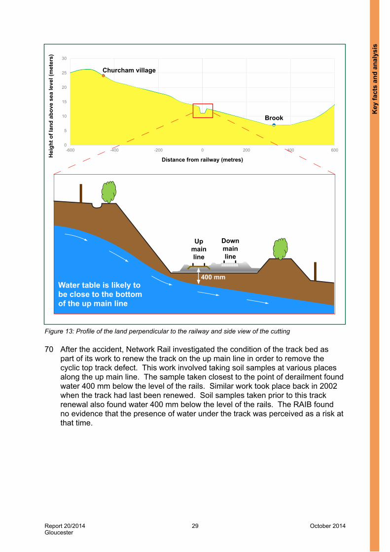
Figure 13: Profile of the land perpendicular to the railway and side view of the cutting
70 After the accident, Network Rail investigated the condition of the track bed as part of its work to renew the track on the up main line in order to remove the cyclic top track defect. This work involved taking soil samples at various places along the up main line. The sample taken closest to the point of derailment found water 400 mm below the level of the rails. Similar work took place back in 2002 when the track had last been renewed. Soil samples taken prior to this track renewal also found water 400 mm below the level of the rails. The RAIB found no evidence that the presence of water under the track was perceived as a risk at that time.
Key
fact
s an
d an
alys
is

Report 20/2014Gloucester
30 October 2014
Point of derailment
118 miles 40 chains
Culvert at 118 miles 25 chains
Path of partially blocked drain Cutting
118 miles 50 chains
Direction of travel
71 The profile of the land perpendicular to the railway line on which the train derailed is shown in figure 13. This shows the height of the land falls steadily over a distance of about 800 metres, from 26 metres above sea level near to Churcham village, to 7 metres above sea level, where a brook flows from east to west before reaching the River Severn. The railway is located about 500 metres from the high point, about 13 metres above sea level. When the railway was built, it was cut through the side of this slope, with the deepest point cut into the slope coincident with the bottom of the cutting slope on the up main line. It is likely that following periods of heavy rainfall, water permeated into the ground above the railway and flowed downhill through the ground towards the brook, causing the local water table to rise. This meant the raised water table was close to the bottom of the track bed on the up main line as shown in figure 13.
72 This is supported by water being found in the soil samples taken here for the track renewals in 2002 and in 2014. The track through the cutting was renewed in March 2014 and this work included the replacement of the track bed. When the old track bed was dug out down to the formation beneath it, Network Rail staff reported seeing water flowing from the bottom of the cutting towards the exposed formation on the up main line.
73 The only drainage present was a drain running along the top of the cutting which might have intercepted some surface water from the adjacent field (figure 14). This drain was partially blocked by vegetation (paragraph 180). However, even if it had been fully functional, due to its position at the top of the cutting, it would not have intercepted the water in the local water table that was flowing downhill under the cutting and beneath the up main line.
Figure 14: Location of the drain running along the top of the cutting
Key facts and analysis

Report 20/2014Gloucester
31 October 2014
118 miles 50 chains
1,5001,2501,000
750500250
-2500
118 miles 40 chains
Direction of travel
Depth below
rail bottom
(mm
)Point of derailment Ballast layer
Trackbed layer
74 The RAIB examined the track in the cutting and noted mud from the formation on the surface of the track throughout the cutting (figure 15). When the top 100 mm of ballast was removed to measure the amount of voiding (paragraph 64), contaminated ballast and mud was found just below the surface (figure 15). The places where the ballast was the most contaminated coincided with the location of the dips in the track.
Figure 15: Mud on the surface and contaminated ballast just below the surface
75 To understand the extent of the ballast contamination, the RAIB obtained data from one of Network Rail’s trains that is fitted with ground penetrating radar. The data recorded when the train last ran over the up main line on 25 July 2013 showed that the ballast was contaminated with mud in a number of places near to where the train derailed (figure 16). The depth of clean ballast is very shallow; it was as shallow as 100 mm in places, which again coincided with the location of the dips in the track.
Figure 16: Ground penetrating radar data processed to show the ballast depth where the train derailed
Key
fact
s an
d an
alys
is

Report 20/2014Gloucester
32 October 2014
Direction of travel
1
1
2
33
4
4
2
55
66
7
78
8
99
Support under the sleepers deteriorates under passing trains leading to voids.Voids lead to the formation of a dip. Size of the dip increases over time if the voiding is not repaired effectively.As trains pass through the dip, the load on each wheel increases when it reaches bottom of the dip.The load decreases on each wheel as it climbs out of the dip.A short distance after the dip, depending on speed, the load on each wheel increases as the suspension responds.Repeated downward forces lead to the support under the sleepers deteriorating over time, leading to voids.Another dip forms in the track if the voiding is not repaired effectively.Again a short distance after the dip, the suspension responds, leading to the formation of another dip.The process continues and results in evenly spaced dips along the track - a cyclic top track defect
76 Over time, water flowing under track had softened the soil in the formation. The softened soil then mixed with water to create mud. The weight of passing trains had caused this mud to seep up through the ballast, forming a feature commonly known as a ‘wet spot’. The wet spot coincided with a loss of support under the sleepers due to the softened formation, resulting in a dip in the track. One dip can then be the trigger for the formation of a cyclic top track defect. Figure 17 shows that when a wheelset passes through the dip, its suspension responds to the change in rail height, so after the wheelset exits the dip the load on its wheels is decreased. Further along the track the suspension will respond again and the load on the wheels will increase, exerting a downward force on the track. If the speed of each passing train is similar, these repeated downward forces will be in the same place and will eventually cause the support under the sleepers in that location to deteriorate. This deterioration leads to voiding and the formation of a new dip. Trains passing over this new dip cause another dip to form and so on. Therefore as trains continued to pass over the up main line, more and more dips had formed at regular intervals, resulting in a cyclic top track defect. Data from Network Rail’s track geometry recording train shows that the cyclic top grew in size from 2010 onwards (paragraph 82).
Figure 17: Formation of a cyclic top track defect
Key facts and analysis

Report 20/2014Gloucester
33 October 2014
Drainage77 The track drainage deficiencies at this location were not addressed during
the two years that the cyclic top track defect worsened. This was an underlying factor12.
78 Table 2 shows the cyclic top was first reported as a defect in June 2011 and data from subsequent runs by track geometry recording trains shows the cyclic top worsened during the next two years. The actions taken by the local Network Rail track maintenance team during this time were focused on repairing the track geometry but these repairs were ineffective (paragraph 80). No work took place to prevent water from flowing under the track, despite the track maintenance team knowing it was a site that had poor drainage.
79 In July 2013, the Section Manager noted during his inspection that there were multiple wet beds throughout the site due to historic drainage issues. As a result of the increasing problems in maintaining the track geometry here, in August 2013 the Track Maintenance Engineer wrote a problem statement to implement a longer term solution. This called for the installation of track drainage along the up main line. However, the realisation that track drainage was needed at this location came too late and its installation had not been progressed by the time of the accident (paragraphs 91 to 92).
Maintenance actions80 The local Network Rail maintenance team was identifying the cyclic top
track defect through its track inspection regime but its short and medium term repairs were ineffective and the long term solution had not been progressed.
81 Table 2 records the history of events relevant to the track between 119 miles 0 chains and 118 miles 40 chains where the train derailed. It shows that from June 2011 onwards, each time a Network Rail track geometry recording train ran, it reported a cyclic top track defect. Also throughout this time, poor vertical track geometry was noted during Section Manager and Track Maintenance Engineer inspections. A Track Maintenance Engineer inspection as far back as January 2009 reported wet beds at this mileage. Numerous Section Manager’s inspections during 2012 and 2013 included reports of poor vertical track geometry, wet beds and poor drainage.
82 Following each inspection, work orders were raised for the defects that were found and each work order was given a time within which the work was required to take place. Records show that the local Network Rail maintenance team were responding to these faults by carrying out short term repairs. However, none of this work was effective or long lasting as the cyclic top, and therefore track quality too, continued to worsen. This can be seen from the data recorded by track geometry recording trains since September 2010 (figure 18). At the same time, medium term work to repair these defects was planned and carried out in October 2013 and a longer term solution was planned from August 2013. The short, medium and long term activities are now considered in turn.
12 Any factors associated with the overall management systems, organisational arrangements or the regulatory structure.
Key
fact
s an
d an
alys
is

Report 20/2014Gloucester
34 October 2014
-25
-20
-15
-10
-5
0
5
10
15
20
25
190820190830190840190850190860190870190880190890190900
Rel
ativ
e he
ight
of r
ails
(mm
)
Relative distance along up main line (metres)
Direction of travel
Point of derailment
2013201220112010
Figure 18: Track geometry recording data from 2010 to 2013
Short term repairs83 For track with poor vertical track geometry, the standard repair method used by
track maintenance teams is measured shovel packing (paragraph 44) using small stones or chippings. However, Railtrack had installed steel sleepers on the up main line at this location in 200213 and their hollow shape (figure 19) meant that measured shovel packing could not be used (paragraph 46).
Figure 19: Steel sleeper profile
13 In 2002, Railtrack had a policy that required all track renewals on secondary lines to install steel sleepers. This policy was suitable for many secondary lines that had low amounts of tonnage passing over them, with the majority of trains comprising light weight passenger vehicles. However, this policy did not take into account those secondary lines, such as the up main line at this location, where the amount of tonnage passing over it was much higher, including a significant number of freight trains.
Side view
Examples of installed steel sleepers
Cross section
view
Key facts and analysis

Report 20/2014Gloucester
35 October 2014
84 Instead, the local track maintenance teams lifted and packed ballast under the sleepers over short distances of up to 4 chains (80 metres). This work was aimed at breaking up the cyclic top track defect into either a length of track interspersed with discrete top defects (paragraph 39) or into several cyclic top track defects which fell into a lesser category, so could be repaired within a longer timescale (see table 1). By doing this, the maintenance team was able to meet the timescales for repairing and signing off the immediate action cyclic top track defects reported by track geometry recording trains (paragraph 109). Witnesses knew this practice was taking place across Western Route. Network Rail was asked if this happened on a national basis but was unable to provide evidence to show whether or not it did.
85 However, this repeated lifting and packing of the track using mechanical tools was ineffective because the ballast was contaminated with mud and it could not be consolidated under the steel sleepers due to their hollow shape. The dips soon reformed once trains began running again. It is also possible that the repeated use of mechanical tools made the track condition worse as it created dust and rounded the corners of the ballast, clogging up the drainage through the track bed and further contaminating the ballast.
Medium term repairs86 For its medium term repair strategy, Network Rail arranged for an on-track
machine to tamp the up main line in an attempt to improve the vertical track geometry and remove the cyclic top fault. This tamping took place in the early hours of 2 October 2013.
87 The preferred on-track machine repair method used by Network Rail at sites with cyclic top and poor ballast conditions would be stoneblowing (paragraph 47). However, this method cannot be used on steel sleeper track due to the sleepers’ hollow shape (in the same way that measured shovel packing cannot be carried out). The track was therefore tamped instead (paragraph 47).
88 The tamping that took place was not carried out to a design that had been prepared in advance, where the amount that the tamper will lift up and move the track is specified. Instead a maintenance tamp took place as the work was planned at short notice. For this type of tamping, the tamper runs over the site to record the track geometry. From this data, a computer on the tamper calculates how much the track should be lifted (but for a maintenance tamp like this, it is usual practice to limit the amount of lift to 30 mm). The tamping then takes place and afterwards the tamper runs over the site again to record the revised track geometry. Records for this tamping show that the maximum amount of lift was limited to 30 mm and variations in the vertical track geometry were still present afterwards but were less severe.
Key
fact
s an
d an
alys
is

Report 20/2014Gloucester
36 October 2014
89 By limiting the tamper’s maximum amount of lift to 30 mm, there was insufficient lift to remove a cyclic top track defect of the magnitude found at this site. Network Rail indicated that tamping sites with cyclic top track defects on steel sleeper track will deliver a longer lasting repair if a significant amount of new ballast is laid down first and the tamping takes place with a very large amount of lift of between 100 and 150 mm. Tamping then compacts the new ballast under the sleepers. This could have been done at this location as there were no limitations on the height of the track. However, witness evidence indicates that tamping in this way is rarely done as it takes longer to do and requires a lot more planning (eg delivery of the new ballast by train must be co-ordinated alongside the tamping). There is no evidence that anyone in the local track maintenance team considered doing this or asking for the tamper to lift the track by more than 30 mm.
90 The improvements to the vertical track geometry on 2 October were short-lived and it is possible that tamping made the condition of the up main line worse. The ground penetrating radar data shown in figure 16 indicates that in July 2013 the clean ballast depth was shallow; it was only 100 mm in places. After the derailment, the RAIB’s site examination identified places where the tamping had brought mud up to the surface, further contaminating the ballast. The effect of the tamping was to stir up the mud with the ballast so once trains began running again the track geometry soon settled back to its pre-tamping state. The Section Manager inspected the site on 4 October and his notes for this inspection record that he was very disappointed with the result and that further work to tamp the track using mechanical tools was needed.
Longer term work91 The Track Maintenance Engineer and Section Manager had recognised that
longer term work was needed at this location to improve the track geometry on the up main line. As poor drainage was cited as the cause of the poor track geometry, the Track Maintenance Engineer proposed that track drainage should be installed along the cess of the up and down main lines. This drainage would dry out the track bed allowing a long lasting repair to be made to the cyclic top track defect.
92 On 14 August 2013, the Track Maintenance Engineer’s team created a problem statement for the installation of track drainage alongside the up main line (paragraph 48). This was followed by another problem statement on 15 October for the installation of track drainage alongside the down main line. At the time of the accident, while both problem statements had been created on TRS, they still had a status of “With TME” which is the first stage of the process. The Track Maintenance Engineer still needed to check the information that had been entered onto TRS before the problem statements were submitted to the next stage. Consequently neither problem statement had reached the RAM (track) team for review. Even if the first problem statement had been progressed soon after it was created in August 2013, so that it was included in the renewal programme, installation of this new drainage was still a long way off.
Key facts and analysis

Report 20/2014Gloucester
37 October 2014
Measuring cyclic top93 The Network Rail maintenance team had no manual way of measuring
the level of cyclic top still present after completing short term repairs or measuring the rate at which the cyclic top worsened once trains began running over it.
94 Network Rail track geometry recording trains generate reports for discrete track geometry faults. These reports include cyclic top track defects and provide a value to indicate the severity of the cyclic top, the number of cycles, the cyclic top wavelength, its start and end locations and the actions that need to be taken (paragraphs 38 to 41).
95 When a track geometry recording train ran over the up main line on 12 September 2013, it reported a cyclic top track defect where the train derailed. This defect had a value of 107 mm, over 11 cycles, at a wavelength of 13 metres, over a distance of 92 yards. Network Rail maintenance responded that day and lifted and packed the track (paragraph 101).
96 The records for this repair work document details such as the method used and the distance over which it took place, but they do not record a value for the cyclic top after the repairs were completed. Ideally, the cyclic top would be measured upon completion of the repair work and measured again once trains have run over it in order to check the track’s vertical geometry has not deteriorated. However, Network Rail track maintenance teams do not have a way of effectively measuring the track’s vertical geometry after they have repaired it or to monitor it afterwards. A series of boards mounted on the rail, which are used for measured shovel packing, could be used to check the vertical alignment of a rail. However, as this repair method could not be used on steel sleeper track (paragraph 83), these boards were not used. Otherwise the track geometry can be inspected by eye.
97 As Network Rail track maintenance teams do not measure the track’s vertical geometry, either after a repair is completed or to monitor it afterwards, it is never compared against the reported cyclic top defect. The effectiveness of the repair in terms of removing or reducing the level of cyclic top can only be measured when the track geometry recording train runs again. For the up main line, this would be about three months later.
Application of speed restriction98 Train 4M36 was permitted to run at speeds up to its maximum speed of
75 mph (121 km/h) over the cyclic top on the up main line.99 While the permissible speed on the up main line at this location is 90 mph
(145 km/h), train 4M36 was a class 4 freight train which was permitted to travel at speeds of up to 75 mph (121 km/h). Train 4M36 was travelling at 69 mph (111 km/h) when it derailed.
100 If a track geometry recording train had passed over the up main line on the day of the accident, it would have reported a cyclic top track defect which would have required the immediate imposition of a 30 mph (48 km/h) emergency speed restriction. The previous six track geometry recording train runs between March 2012 and September 2013 had all required the immediate imposition of a 30 mph (48 km/h) emergency speed restriction (see table 2).
Key
fact
s an
d an
alys
is

Report 20/2014Gloucester
38 October 2014
101 After the passage of the last track geometry recording train on 12 September, the signaller at Gloucester signal box stopped each train on the up main line and instructed its driver to pass over this section of track at a speed of no greater than 20 mph (32 km/h). This continued until a track maintenance team responded and arrived at the site. The team had access to the track from 20:22 hrs to 21:38 hrs, by which time it was dark. Records for the work state that the team lifted and packed the track over a length of 44 yards. After completing this work, they gave permission for the 30 mph (48 km/h) emergency speed restriction to be removed so trains could once again run over this track up to their maximum permitted speed.
102 It is not feasible that the track maintenance team could have made an effective repair to a cyclic top track defect of this magnitude (paragraph 95), using manual methods, in this amount of time and in darkness. Instead they did work in accordance with a known practice which aimed to break up the cyclic top track defect into a number of discrete top defects (paragraph 84). The local track maintenance team did plan follow-up repair work which took place on 24 September. This was also followed by planned tamping (paragraph 86) on 2 October. All of this work proved to be ineffective and trains continued to run at up to their maximum permitted speed over the cyclic top track defect.
103 When a cyclic top track defect is found that falls into the immediate action category, NR/L2/TRK/001/Mod11 not only requires the imposition of a 30 mph (48 km/h) emergency speed restriction, but also requires the Section Manager to sign off the defect as repaired within 36 hours. Once the fault is signed off as repaired, the speed restriction can also be removed.
104 If a cyclic top track defect has reached the point where it falls into the immediate action category, then it can only be effectively repaired using a stoneblower or possibly a tamper provided the ballast is not contaminated. It is not feasible for a Section Manager to arrange for the track to be stoneblown or tamped within 36 hours. This leaves the Section Manager with little option other than to use maintenance staff to carry out repairs using manual methods. This work will not effect a lasting repair as it will be limited to breaking up the cyclic top track defect into a number of discrete top defects as discussed earlier. However, it does allow the Section Manager to meet the 36 hour repair deadline, followed by the removal of the speed restriction.
105 Network Rail has acknowledged that it is very unlikely that an effective repair using an on-track machine can be completed within 36 hours. Its interpretation of this requirement is that it has a short timescale to highlight the importance of the defect. If an on-track machine repair cannot be completed within 36 hours, maintenance staff should carry out manual repairs to reduce the severity of the defect in the short term, but the emergency speed restriction should remain in place until the more effective on-track machine repair can be carried out. This interpretation is not explained in NR/L2/TRK/001/Mod11 and there is no evidence that this was happening at Gloucester. Here, only short term manual repairs took place in order to meet the 36 hour deadline before the emergency speed restriction was then removed.
Key facts and analysis

Report 20/2014Gloucester
39 October 2014
106 The overall poor quality of the vertical track geometry also meant that Network Rail should have imposed a speed restriction to comply with NR/L2/TRK/001/mod11. Figure 20 shows the SD chart (paragraphs 42 to 43) covering the point of the derailment after the last ten track geometry recording runs up until June 2013. It shows how the eighth of a mile section where the derailment happened had worsened over time.
Figure 20: SD chart for the up main line
107 By June 2013, its SD value was in the maximum band, the ‘super-red’ category. Once it became a super-red site, NR/L2/TRK/001/mod11 required the Track Maintenance Engineer to take action to improve its quality. NR/L2/TRK/001/mod11 also states that if the action undertaken is not sufficient to move the SD value out of the maximum band then a speed restriction must be imposed.
108 When the next track geometry recording run took place in September, the SD recorded for this eighth of a mile section was again in the super-red category. At that point, due to its continuing poor quality, the Track Maintenance Engineer should have reduced the permitted speed over that eighth mile section of the up main line to 60 mph (97 km/h) in accordance with the requirements of NR/L2/TRK/001/mod11. The Track Maintenance Engineer did not identify that this needed to be done because the meeting to review the output from the September track recording run did not take place due to staff attending to other activities. Witnesses stated that the imposition of necessary speed restrictions would have been supported by Network Rail management.
Key:
No data
Good
Satisfactory
Poor
Very poor
Super-red
Work record
Eighth mile section on which train derailed
1.65
1.84
1.74
1.86
16-Jun-11
17-Mar-11
15-Dec-10
Track history
1.95
1.91
1.9
2.14
1.82
1.81
13-Jun-13
15-Mar-13
13-Dec-12
13-Sep-12
15-Dec-11
15-Sep-11
15-Mar-12
4.2
4.2
1.83
1.41
1.4
6.09
5.28
4.89
4.51
4.14
4.18
1.27
1.51
1.42
1.41
1.1
1.07
0.93
0.81
1.14
3.23
2.1
1.35
1.26
1.26
1.38
1.43
1.47
4.26
4.33
4.4
1.51
1.53
1.53
1.29
2.84
1.78
4.79
3.43
118 miles0 chains
118 miles10 chains
118 miles
1.45
1.69
1.84.0
1.08
1.03
1.01.8
1.95
1.7
118 miles60 chains
118 miles70 chains
119 miles0 chains20 chains
118 miles30 chains
118 miles40 chains
118 miles50 chains
1.74 1.321.8 1.77 0.92 1.25 5.29 4.39
0.92
1.04
0.98
0.97
5.06
5.01
4.61
4.321.96 1.73
2.02
1.93
1.93
Key
fact
s an
d an
alys
is

Report 20/2014Gloucester
40 October 2014
109 Witnesses stated that cyclic top track defects are seen as a derailment risk, to freight trains in particular, and they knew that the primary risk mitigation is a reduction in speed. However, as soon as Network Rail maintenance staff completed short term repair work to comply with the 36 hour deadline for signing off the defect, they removed the speed restrictions, even though they knew from their experience that a cyclic top track defect requiring a 30 mph (48 km/h) speed restriction would be found the next time the track geometry recording train ran. It is possible that because derailments caused by this type of track defect are now much less frequent than in the past (paragraph 190), Network Rail’s track maintenance staff have become less aware of the importance of keeping these speed restrictions in place. Rather than leaving the speed restriction in place until it could be shown that the cyclic top had been effectively repaired, instead maintenance staff were focused on complying with the deadline set in NR/L2/TRK/001/Mod11 for doing the repair. After the cyclic top track defect had been signed off, further repairs were sometimes planned. However, there is no evidence that any additional inspections, beyond those required by the track inspection regime, were planned to check the effectiveness of any repair work.
Absence of challenge110 There was an absence of management challenge to the repeated ineffective
repair of the cyclic top and removal of emergency speed restrictions. This was an underlying factor.
111 The Track Maintenance Engineer and other staff based at Gloucester maintenance depot were all aware of the cyclic top track defect at this location. For over 18 months, cyclic top track defects requiring a 30 mph (48 km/h) emergency speed restriction were being reported each time the track geometry recording train ran as the repair work they planned and carried out was ineffective. During this time the track geometry quality also fell into the super-red category. However, no one outside the local maintenance organisation was aware of the ongoing problem site.
112 The cyclic top track defect and poor track geometry quality were not highlighted by any of Network Rail’s reporting processes. On the railway line from Severn Tunnel Junction to Gloucester, the Track Maintenance Engineer at Gloucester is responsible for the section from 128 miles 0 chains through to Gloucester station at 114 miles 4 chains. On this section of railway, there was just one half mile long section, from 119 miles 0 chains to 118 miles 40 chains, which had poor quality vertical track geometry due to the cyclic top. The overall quality of the track geometry on the 14 miles of railway that the Track Maintenance Engineer was responsible for was good. Therefore neither the Infrastructure Maintenance Engineer (who the Track Maintenance Engineer reports to) nor the Route Asset Manager responsible for track assets knew about it.
113 There was no senior management oversight to question why this fault was being repeatedly found, there was no support provided by the RAM (track) team to help resolve the problem, and there was no challenge to the repeated removal of the 30 mph (48 km/h) emergency speed restrictions which were imposed to mitigate the derailment risk from the cyclic top track defect.
Key facts and analysis

Report 20/2014Gloucester
41 October 2014
IDA wagon vertical ride performance114 The IDA wagon is susceptible to wheel unloading at its rear bogie when
responding to cyclic changes in vertical track geometry (‘cyclic top’), especially with a partial load, such as an empty 45 foot long curtain-sided container. This was not identified when the wagon was approved for use on Network Rail’s infrastructure.
115 In order to reach a more definite understanding of the key factors that led to this derailment and their significance, dynamic modelling was undertaken using the VAMPIRE® computer software simulation package.
116 Wabtec provided a vehicle model for the IDA wagon which it had used when the prototype wagon was being designed. However, Wabtec had not updated or validated the model and it had not been used as a source of evidence for any of the wagon’s approval work. Data from this model, design information for the production IDA wagon and measurements from the wagon that derailed were used to create a new vehicle model. This new model was validated against practical test results recorded when the prototype IDA wagon underwent its vehicle approval. The results from the model and practical tests closely matched. Further models were then created to represent the production IDA wagon that derailed in different load conditions: tare, fully laden and partially laden as at the time it derailed (paragraph 17). As the wagon that derailed was new, having only been in service for about four weeks, it was not necessary for the vehicle models to account for wear to components.
117 To model the derailment mechanism, a track model which included the cyclic top track defect was created using data from track surveys and data recorded by the track geometry recording train that ran on 12 September 2013. When the partially laden vehicle model was run over the track model at 69 mph (111 km/h), the right wheel of the rear wheelset lifted up and landed on the rail head, and then derailed to the right about 5 metres later. This matched the derailment marks as found on site, with the predicted point of derailment in the simulation within 20 metres of the actual point of derailment.
118 To understand how the propensity to derail changed when the amplitude of the cyclic top track defect was varied, further track models were created. The data for the vertical track geometry was scaled by factors of 90, 80, 70, 60 and 50% to create a further five track models. To understand the level of cyclic top in each of these track models, the data was filtered at a wavelength of 13 metres and the algorithm referred to in paragraph 40 was then applied to give a cyclic top value. The results are shown in table 4. The cyclic top values that would trigger the most significant track maintenance action are shown in red, along with the corresponding track maintenance action that it would require.
Key
fact
s an
d an
alys
is

Report 20/2014Gloucester
42 October 2014
Vertical track geometry data scaling factor
Cyclic top (mm)Action to be taken by track maintenance
Left rail Right rail Both
100% 40.50 42.32 82.82 Immediate 30 mph (48 km/h) emergency speed restriction. Correct within 36 hours
90% 32.12 34.10 66.22 Immediate 30 mph (48 km/h) emergency speed restriction. Correct within 36 hours
80% 28.47 27.18 55.65 Immediate 30 mph (48 km/h) emergency speed restriction. Correct within 36 hours
70% 21.79 23.69 45.48 30 mph (48 km/h) emergency speed restriction applied within 36 hours. Correct within 30 days
60% 16.76 20.19 36.95 Correct within 60 days
50% 11.01 14.43 25.44 None
Table 4: Track model cyclic top values
119 Simulations were carried out running the tare, fully laden and partially loaded vehicle models over each track model, at a range of speeds from 30 mph (48 km/h) to 70 mph (113 km/h) in 5 mph (8 km/h) increments. The results are shown in figure 21.
120 Figure 21 shows that in its fully laden condition, the IDA wagon is not at risk of derailing at any speed on any of the track models. This is because the predicted amount of wheel unloading is low and there is no wheel lift.
121 Figure 21 shows that in its tare condition, at least one of the IDA wagon’s wheels is predicted to completely unload when passing over the cyclic top in the 60% track model at a speed of 65 mph (105 km/h) or greater. Table 4 shows that cyclic top level of this magnitude would not require a speed restriction to be imposed, and could remain un-corrected for up to 60 days. However, the predicted wheel lift is 5 mm, so the risk of derailment is relatively small. As the level of cyclic top increases, the predicted amount of wheel lift increases with a corresponding increase in the risk of a derailment14. For the 80, 90 and 100% track models, at the higher speeds, the wheel lift becomes great enough for a flange to pass over the rail head (for these track models, a 30 mph (48 km/h) speed restriction should be in place and at this low speed the predicted amount of wheel unloading is low with no wheel lift). The greatest predicted wheel lift is 44 mm on the 100% track model at 70 mph (113 km/h). Although derailment is not predicted by this simulation, the amount of predicted wheel lift means that only a small lateral force is needed for a derailment to occur.
14 The study commissioned by the RAIB reported that once the predicted wheel lift reaches 5 mm or more, the margin of safety against derailment begins to reduce significantly. This 5 mm threshold is not formally specified, it was chosen based on the experience of the vehicle dynamics consultant. The risk of derailment is significant once the wheel flange is lifted higher than the rail head, which for the wheels fitted to IDA wagons, will be when the predicted wheel lift is greater than 30 mm. Only a small amount of lateral force is then needed to derail the wheel (eg such as from going around a curve).
Key facts and analysis

Report 20/2014Gloucester
43 October 2014
Track models (see table 4)
Deg
ree
of c
yclic
top
(trac
k m
aint
enan
ce
actio
n re
quire
d)
No
inte
rven
tion
60 d
ay re
pair
30 m
ph E
SR w
ithin
36
hou
rs a
nd re
pair
with
in 3
0 da
ys
Imm
edia
te 3
0 m
ph
ESR
and
repa
ir w
ithin
36
hour
s
Speed (mph) Wagon 50% 60% 70% 80% 90% 100%
30
IDA laden
35 40 45 50 55 60 65 70 30
IDA tare
35 40 45 50 55 60 65 70 30
IDA part laden
35 40 45 50 55 60 65 70 X X
X
Wheel unloaded by less than 80% Wheel fully unloaded (100%)
Derailment predictedWheel unloaded by 80% or more but less than 100%
Figure 21: Simulation results for IDA wagons
Key
fact
s an
d an
alys
is
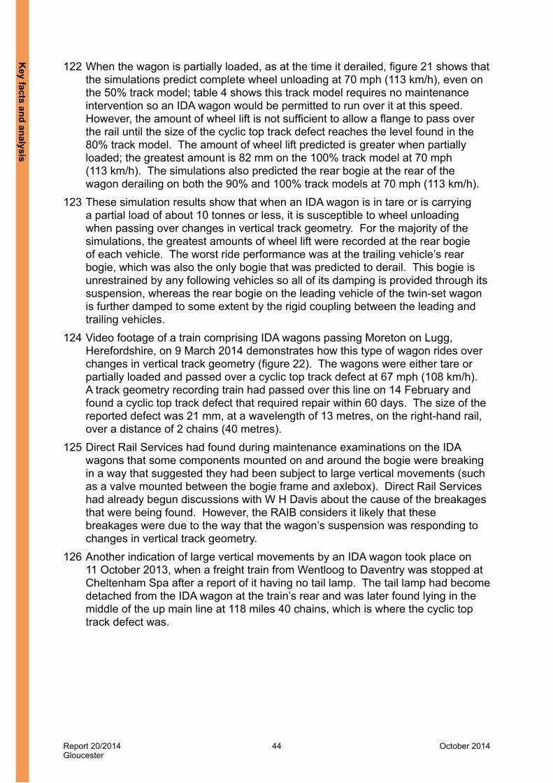
Report 20/2014Gloucester
44 October 2014
122 When the wagon is partially loaded, as at the time it derailed, figure 21 shows that the simulations predict complete wheel unloading at 70 mph (113 km/h), even on the 50% track model; table 4 shows this track model requires no maintenance intervention so an IDA wagon would be permitted to run over it at this speed. However, the amount of wheel lift is not sufficient to allow a flange to pass over the rail until the size of the cyclic top track defect reaches the level found in the 80% track model. The amount of wheel lift predicted is greater when partially loaded; the greatest amount is 82 mm on the 100% track model at 70 mph (113 km/h). The simulations also predicted the rear bogie at the rear of the wagon derailing on both the 90% and 100% track models at 70 mph (113 km/h).
123 These simulation results show that when an IDA wagon is in tare or is carrying a partial load of about 10 tonnes or less, it is susceptible to wheel unloading when passing over changes in vertical track geometry. For the majority of the simulations, the greatest amounts of wheel lift were recorded at the rear bogie of each vehicle. The worst ride performance was at the trailing vehicle’s rear bogie, which was also the only bogie that was predicted to derail. This bogie is unrestrained by any following vehicles so all of its damping is provided through its suspension, whereas the rear bogie on the leading vehicle of the twin-set wagon is further damped to some extent by the rigid coupling between the leading and trailing vehicles.
124 Video footage of a train comprising IDA wagons passing Moreton on Lugg, Herefordshire, on 9 March 2014 demonstrates how this type of wagon rides over changes in vertical track geometry (figure 22). The wagons were either tare or partially loaded and passed over a cyclic top track defect at 67 mph (108 km/h). A track geometry recording train had passed over this line on 14 February and found a cyclic top track defect that required repair within 60 days. The size of the reported defect was 21 mm, at a wavelength of 13 metres, on the right-hand rail, over a distance of 2 chains (40 metres).
125 Direct Rail Services had found during maintenance examinations on the IDA wagons that some components mounted on and around the bogie were breaking in a way that suggested they had been subject to large vertical movements (such as a valve mounted between the bogie frame and axlebox). Direct Rail Services had already begun discussions with W H Davis about the cause of the breakages that were being found. However, the RAIB considers it likely that these breakages were due to the way that the wagon’s suspension was responding to changes in vertical track geometry.
126 Another indication of large vertical movements by an IDA wagon took place on 11 October 2013, when a freight train from Wentloog to Daventry was stopped at Cheltenham Spa after a report of it having no tail lamp. The tail lamp had become detached from the IDA wagon at the train’s rear and was later found lying in the middle of the up main line at 118 miles 40 chains, which is where the cyclic top track defect was.
Key facts and analysis
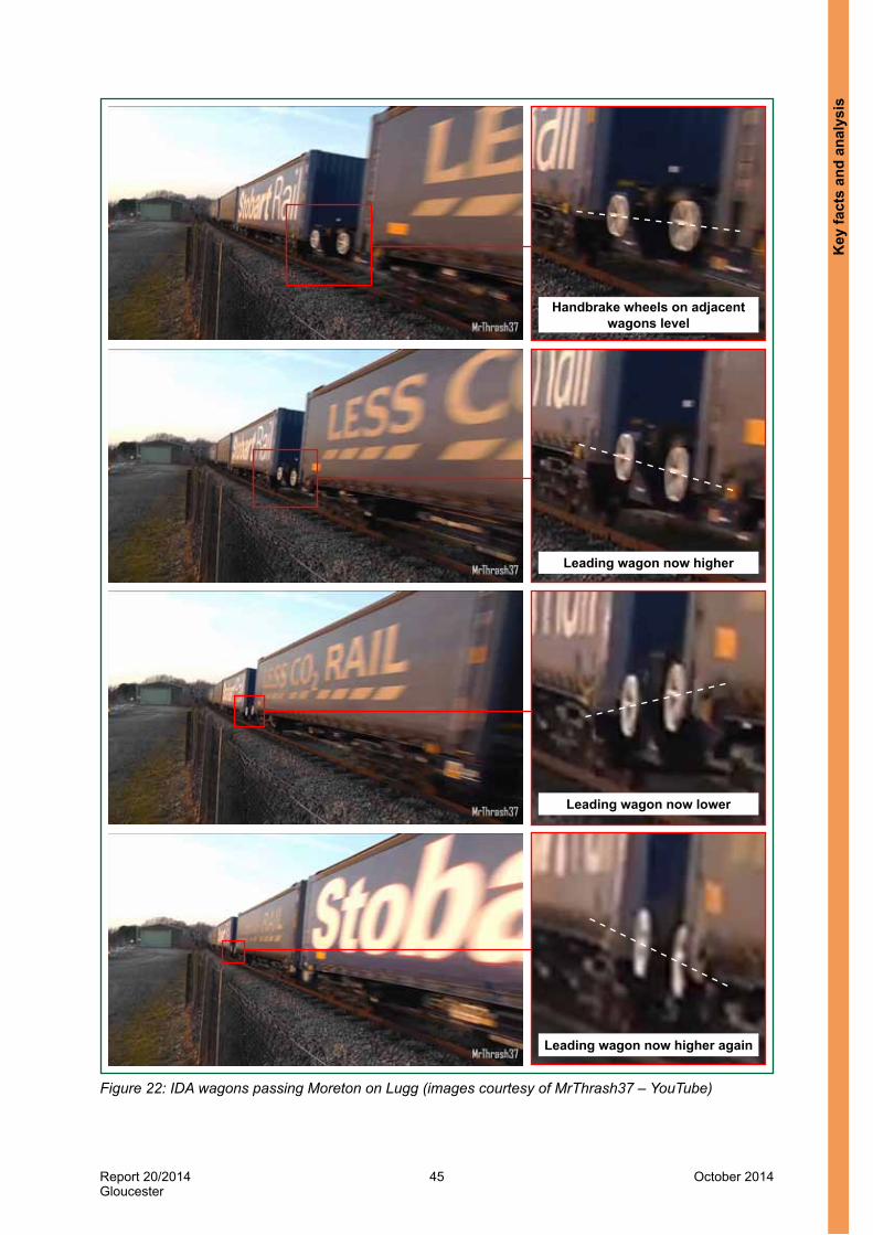
Report 20/2014Gloucester
45 October 2014
Handbrake wheels on adjacent wagons level
Leading wagon now higher
Leading wagon now lower
Leading wagon now higher again
Figure 22: IDA wagons passing Moreton on Lugg (images courtesy of MrThrash37 – YouTube)
Key
fact
s an
d an
alys
is

Report 20/2014Gloucester
46 October 2014
Inner spring (green)Outer spring (yellow)Wedges (red)Friction surfaces (blue/cyan)
127 The suspension on the IDA wagon uses friction to provide its damping. The primary suspension at the end of each axle has four sets of springs, each comprising an inner and an outer spring (figure 23). With no load other than the weight of the wagon itself (ie tare), only the outer spring is in contact between the axlebox and the bogie frame. As the load on the wagon is increased, the inner spring also comes into contact and this increases the vertical stiffness of the suspension. Figure 24 shows that the inner spring comes into contact with a load of 5.76 tonnes on the wagon (2.88 tonnes on each bogie). When the wagon has a partial load on it, such as an empty curtain-sided container which weighs 5.99 tonnes, the inner spring is just in contact but with a comparatively light load. This is generally the worst condition for vertical ride performance as vertical inputs from the track then cause the inner springs to move into and out of contact leading to rapid changes in the suspension stiffness. These changes in stiffness, combined with the light load and the commensurately small amount of friction damping, give rise to a bigger response to vertical track inputs than is seen for either the tare or fully laden wagon.
Figure 23: The primary suspension on an IDA wagon
Key facts and analysis

Report 20/2014Gloucester
47 October 2014
0
10
20
30
40
50
60
70
0 10 20 30 40 50 60
Spring deflection (mm)
Graph showing wagon load against spring deflection from tare to laden
load / spring deflection
Fully laden
Point where stiffnesschanges
Wag
on lo
ad (t
onne
s)
5.760 tonnes
1800 mm wheelbase
730 mm deck height above rail level at tare
9248 mm bogie centres
14752 mm over headstocks
Figure 24: Wagon load versus spring deflection graph
128 The response to vertical track inputs seen with both a tare and a partially loaded wagon can result in large amounts of wheel lift (paragraphs 121 to 122). The IDA wagon has a very low profile so it can carry 9 foot 6 inch (2.9 metre) high containers over routes which these containers would otherwise be prohibited from. With no load on it, the wagon’s deck is just 730 mm above rail level (figure 25), which is achieved by using small wheels measuring 577 mm in diameter and a compact bogie design. The bogie design is also constrained by the maximum height limit for the wagon when loaded. The maximum amount of upward vertical movement within the suspension is 25 mm. For any further vertical movement after this distance, the suspension becomes very stiff with no damping, as the end of the vehicle, including its bogie and wheels, is lifted up. This behaviour is evidenced by damage found during maintenance examinations. It would also result in large vertical accelerations at the bogie pivots, as found during the actual and simulated on-track testing (see paragraphs 134 to 149).
Figure 25: Dimensions of an IDA wagon (courtesy of W H Davis)
Key
fact
s an
d an
alys
is

Report 20/2014Gloucester
48 October 2014
129 To understand how the ride performance of the IDA compared to other widely used types of container flat wagon, the simulations were repeated for:l a 60 foot (18.3 metres) long container flat wagon, fitted with a Y25 series bogie
which has a coil spring primary suspension; andl a 60 foot (18.3 metres) long type FFA container flat wagon, which has a
three-piece bogie with coil spring and rubber secondary suspension.130 Vehicle models in tare, part laden and fully laden were used for both. The part
laden condition that was chosen placed the suspension just in contact with the inner springs. The results of simulations in their part laden condition are summarised in figure 26.
131 The simulations for both of these wagons showed their overall ride performance was good over all of the track models and derailment risk was comparatively small. The predicted amounts of wheel lift were no greater than 8 mm for both wagons, even on the 90 and 100% track model at the higher speeds.
132 For completeness, the simulations were also repeated using a generic model of a laden two axle tank wagon, which is a type of wagon that has a history of derailments on cyclic top track defects. The simulations predicted high levels of wheel unloading on all of the track models, at all speeds from 30 mph (48 km/h) to 70 mph (113 km/h). Wheels became completely unloaded at speeds above 55 mph (89 km/h) on the 80, 90 and 100% track models, with predicted amounts of wheel lift up to 98 mm. Derailment was predicted at either 65 mph (105 km/h) or 70 mph (121 km/h) on the 70, 80, 90 and 100% track models, albeit these wagons have a maximum speed of 60 mph (97 km/h).
133 The dynamics modelling showed that the ride performance of the IDA wagon over cyclic top track defects is worse in comparison to other container flat wagons. However, this behaviour was not identified during the work that gained approval for these wagons to be used on Network Rail’s infrastructure. This arose due to a combination of the following:l The IDA wagon’s ride performance was not tested with a partial load such as an
empty 45 foot long curtain-sided container. If it had been tested, it is probable that the IDA wagon would not have met the ride performance criteria in Railway Group Standard GM/RT2141 issue 3 (paragraph 134).
l The approval process for the IDA wagon did not assess the wagon’s ride performance when loaded with a partial load such as an empty 45 foot long curtain-sided container (paragraph 150).
l The approval process for the IDA wagon did not specifically assess the wagon’s ride performance in response to changes in vertical track geometry (paragraph 158).
Each of these factors is now considered in turn.
Key facts and analysis
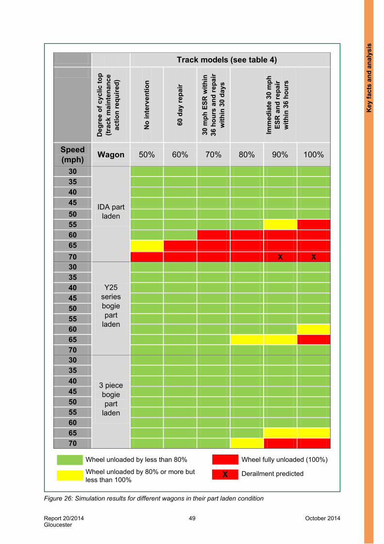
Report 20/2014Gloucester
49 October 2014
Track models (see table 4)
Deg
ree
of c
yclic
top
(trac
k m
aint
enan
ce
actio
n re
quire
d)
No
inte
rven
tion
60 d
ay re
pair
30 m
ph E
SR w
ithin
36
hou
rs a
nd re
pair
with
in 3
0 da
ys
Imm
edia
te 3
0 m
ph
ESR
and
repa
ir w
ithin
36
hour
s
Speed (mph) Wagon 50% 60% 70% 80% 90% 100%
30
IDA part laden
35 40 45 50 55 60 65 70 X X 30
Y25 series bogie part
laden
35 40 45 50 55 60 65 70 30
3 piece bogie part
laden
35 40 45 50 55 60 65 70
X
Wheel unloaded by less than 80% Wheel fully unloaded (100%)
Derailment predictedWheel unloaded by 80% or more but less than 100%
Figure 26: Simulation results for different wagons in their part laden condition
Key
fact
s an
d an
alys
is
Report 20/2014Gloucester
50 October 2014
Testing ride performance with a partial load134 The IDA wagon’s ride performance was not tested with a partial load such
as an empty 45 foot long curtain-sided container. If it had been tested, it is probable that the IDA wagon would not have met the ride performance criteria in Railway Group Standard GM/RT2141 issue 3.
135 The IDA wagon was tested to demonstrate that its ride performance met the requirements of the TSI for freight wagons that was issued in 2006. To ensure acceptable resistance against derailment, this TSI included a section named ‘safety against derailment and running stability’. This stated the mandatory limits for the lateral and vertical forces between the wheel and rail, which were based on factors related to the track infrastructure, such as curvature.
136 Instrumented wheelsets are needed to measure the lateral and vertical forces between the wheel and the rail. In Great Britain, these are not generally used because historically ride performance has been assessed by following a different approach, which is described in GM/RT2141. As the IDA wagons were only to be used in Great Britain, the assessors applied GM/RT2141, using it as an NTR to address the ride performance requirements in the 2006 TSI for freight wagons (which is an open point). Witness evidence stated that the tests in GM/RT2141, which apply to running on track in Great Britain, were deemed to be more onerous than those in the TSI and so by demonstrating compliance with the requirements in GM/RT2141, the ride performance required by the TSI would be met.
137 In 2008, testing took place using the prototype IDA wagon which followed the requirements in issue 2 of GM/RT2141, specifically Appendix D (issue 2 was the version that was current at that time). Static tests took place first, which included wheel unloading tests (these show how the suspension reacts to track twist). Following these, the wagon was instrumented and the vertical and lateral accelerations of the body over the centre of each bogie were measured while the wagon was hauled over a circular route comprising a number of representative track conditions. These test runs took place with the wagon in its tare condition and also fully laden.
138 The measurements for each on-track test run were analysed, looking for the number of peak accelerations above defined values. The results were then plotted on a graph and compared with an acceptance curve as defined in issue 2 of GM/RT2141. The results showed ride performance was marginally non-compliant to the acceptance curve at times, both in its tare and fully laden conditions. On sections of jointed track between Crewe and Derby at speeds above 50 mph (80 km/h), the distribution of vertical accelerations peaks exceeded the acceptance curve at the trailing bogie of the leading vehicle and the trailing bogie of the rear vehicle. An example of one of the recorded non-compliances is shown in figure 27.
Key facts and analysis

Report 20/2014Gloucester
51 October 2014
100
10
1
0.1
0.010 0.1 0.2 0.3 0.4 0.5 0.6 0.7 0.8 0.9 1
Unacceptable
Acceptance curveRecorded plot
Cumulative peak accelerations as a % of total vs. acceleration
Plot for rear bogie of leading vehicle exceeds issue 2 acceptance curve
Acceptable
Perc
enta
ge e
xeed
ence
Body vertical acceleration (g)
Figure 27: Peak counting plot for tare IDA wagon at 54 mph (87 km/h) on jointed track (from actual on-track tests)
139 The test report for the on-track testing noted these failures and at the end of 2008, a deviation to GM/RT2141 for ride performance was obtained from Rolling Stock Standards Committee (deviation reference 08/240/NC). This allowed W H Davis to loan the prototype IDA wagon to a number of freight operating companies so they could evaluate the prototype IDA by using it in their trains. The argument made for a deviation was that changes were being proposed to GM/RT2141 which included the introduction of a new acceptance curve for bogie freight wagons on jointed track. The IDA wagon test results complied with this new curve, so once it was issued the deviation would no longer be needed.
140 In 2007, RSSB had commissioned a study to review the acceptance curve in GM/ RT2141 as a number of bogie freight wagons had not met its requirements when tested on jointed track, but had subsequently been seen to operate satisfactorily. This work led to RSSB introducing a new acceptance curve specifically for bogie freight wagons on jointed track as shown in figure 28. RSSB based the new acceptance curve on the existing curve and changed the margin of safety only in areas where it considered it had existing experience, such as where the ride performance of wagons with derogations against the existing curve had been shown to be acceptable for some time. The new acceptance curve for bogie freight wagons on jointed track was published in issue 3 of GM/RT2141 in June 2009.
141 The test report for the on-track testing also recommended that the wagons’ ride performance be investigated, including testing with a partial load at the point where the primary suspension stiffness changes (paragraphs 137 to 139). GM/RT2141 issue 2 did not specifically require testing in a partially loaded condition but it did state that testing should be ‘sufficient to allow all representative conditions to be assessed’.
Key
fact
s an
d an
alys
is

Report 20/2014Gloucester
52 October 2014
New curve
Existing curve
Figure 28: New acceptance curve for bogie freight vehicles on jointed track
142 One of the other differences between issue 2 (dated October 2000) and issue 3 (dated June 2009) of GM/RT2141 was the inclusion of a new section detailing how different loading conditions need to be considered when assessing resistance to derailment. This change had been made in response to a RAIB recommendation that was made after a container-carrying wagon had derailed at Duddeston, near Birmingham15. GM/RT2141 issue 3 notes that vehicle condition and load can affect the resistance to derailment. It lists the test conditions that should be considered and includes ‘vehicle weight distribution (for example tare, laden, partially laden)’. While there are numerous loading conditions that can apply to a container-carrying wagon, a key partial load test condition for the IDA wagon would have been one that tested the suspension at its stiffness change point (figure 24). An empty 45 foot curtain‑sided container is just the right weight to place the suspension at its stiffness change point, and as the IDA wagon was primarily designed to carry 45 foot long containers, this would have been a representative test condition.
143 The IDA wagon was approved without any testing being carried out with a partial load (paragraph 150). Since this time there have been a number of changes to the standards for testing ride performance which means testing with a partial load is more likely to take place. The latest version of the TSI for freight wagons which was issued in 2013 (paragraph 50) makes specific reference to EN 14363:2005 (paragraph 54). Section 5.4.3.5 of EN 14363:2005 describes the loading conditions required for the on-track testing and explains that testing with a partial load should be undertaken if this is found to be an unfavourable condition.
15 RAIB report 16/2008, Derailment at Duddeston Junction, Birmingham, 10 August 2007
Key facts and analysis

Report 20/2014Gloucester
53 October 2014
144 RSSB provides guidance on applying EN 14363:2005 to freight vehicles in document GM/GN2688, issue 2, ‘Guidance on Designing Rail Freight Wagons for use on the GB Mainline Railway’. It explains that a partial load test is required if a wagon has a non-linear suspension, as this is likely to be the worst-case loading condition. It also states that for wagons with springs that only come into contact when laden (like the IDA wagon), the worst-case can be when the vehicle is partially laden, just sufficient to contact these springs (ie at its stiffness change point). However, the IDA wagon was designed, tested and approved before this guidance was added to issue 2 and published in 2013.
145 As the ride performance of a partially laden IDA wagon had never been tested, the RAIB simulated it as part of the study it commissioned. The study included an assessment of the IDA wagon against all of the ride performance requirements in GM/RT2141 issue 3. Resistance to derailment was assessed over a series of track twists as defined in the standard. The wagon passed all of the simulations and demonstrated a very good resistance to low speed flange climb derailment.
146 The study also included a series of simulated on-track tests over five routes that represented a mixture of track types. These were equivalent to the on-track tests that took place in 2008. They repeated the tare and fully laden tests, and also included partially laden tests. For the partially laden tests, the wagon model was loaded the same as the wagon that derailed, ie the trailing vehicle was loaded with 5.99 tonnes (the same weight as an empty 45 foot curtain-sided container). The simulations were carried out over a range of speeds from 35 mph (56 km/h) to 75 mph (121 km/h) in 5 mph (8 km/h) increments.
147 The results for the tare and fully laden simulations were very similar to the actual on-track test results. During the simulated tests, the ride performance of the IDA wagon did not meet the GM/RT2141 issue 2 acceptance curve on four occasions in tare and once when fully laden. Each exceedance was recorded at the rearmost bogie, while running on jointed track, at a range of speeds between 60 mph (97 km/h) and 70 mph (113 km/h). When the results were compared against the issue 3 acceptance curve, there was only one exceedance. This was the rearmost bogie of a tare vehicle, running at 70 mph (113 km/h) over jointed track, whereas the actual on-track tests over jointed track were at 54 mph (87 km/h).
148 The results for the partially laden simulations found that the ride performance did not meet the GM/RT2141 issue 2 acceptance curve on twelve occasions. Each exceedance was recorded while running on jointed track, at a range of speeds between 50 mph (80 km/h) and 70 mph (113 km/h). Seven exceedances were at the rear bogie of the trailing vehicle and five at the rear bogie of the leading vehicle. When the results were compared against the issue 3 acceptance curve, there were still four exceedances at the rear bogie of the trailing vehicle, at a range of speeds between 60 mph (97 km/h) and 70 mph (113 km/h). One of the exceedances recorded at 60 mph (97 km/h) is shown in figure 29. Therefore these test results did not meet the revised ride performance criteria in issue 3 of GM/RT2141. Similar to the simulation results for the track geometry at Gloucester (paragraph 123), the worst ride performance was recorded at the unrestrained rear bogie of the trailing vehicle.
Key
fact
s an
d an
alys
is

Report 20/2014Gloucester
54 October 2014
Unacceptable
Plot for rear bogie of trailing vehicle exceeds issue 3 acceptance curve
Acceptable
Perc
enta
ge e
xeed
ence
Body vertical acceleration (g)
Leading vehicle front bogieLeading vehicle rear bogieTrailing vehicle front bogieTrailing vehicle rear bogieAcceptance curve
100
10
1
0.1
0.010.0 0.30.1 0.40.2 0.5 0.6 0.7 0.8 0.9 1.0
Figure 29: Peak counting plot for a part laden IDA wagon at 60 mph (97 km/h) on jointed track (from simulated on-track tests)
149 The study concluded that if the actual on-track testing had included a test with a wagon partially loaded so the suspension was at its stiffness change point, it is probable that the wagon would not have passed the acceptance tests.
Assessing ride performance with a partial load150 The approval process for the IDA wagon did not assess the wagon’s ride
performance when loaded with a partial load such as an empty 45 foot long curtain-sided container.
151 In 2010, the work to approve the first batch of IDA wagons (IDA-P) took place. When the Network Rail Vehicle Conformance Group assessor approving the IDA-P wagon looked at ride performance, he found that the ride performance test results did not comply with the curve in GM/RT2141 issue 2 and noted the recommendation in the on-track test report that called for further testing with a partial load (paragraph 141). The assessor recorded in the documentation for the approval work his view that the test results now met a new curve for bogie freight wagons on jointed track that had been published in issue 3 of GM/RT2141 in 2009 (paragraph 140).
152 The assessor also stated in the documentation for the approval work that the static test results for wheel unloading and resistance to flange climbing showed that ride performance should be acceptable with a partial load, and concluded that the requirements for ride performance had been met. The RAIB found no evidence to support the statement that a wagon’s resistance to flange climbing can be used to show that its vertical ride performance will be acceptable. The dynamic modelling of the IDA wagon has shown this argument has no basis, as the IDA wagon has a very good resistance to flange climbing (paragraph 145) but its ride performance is susceptible to changes in vertical track geometry (paragraphs 121 to 123).
Key facts and analysis
Report 20/2014Gloucester
55 October 2014
153 The assessor did raise concerns about whether on-track testing to the requirements in GM/RT2141 demonstrated compliance with the TSI for freight wagons. In 2011, after seeking guidance from RSSB, the assessor called for the data from the tare and fully laden on-track tests (recorded in 2008) to be analysed to check compliance with the safety and ride requirements of EN 14363:2005. The track that was used was first categorised into either zone 1 or zone 2 track16. The recorded data was analysed and the results showed the IDA wagon generally complied with the advisory ride acceleration limits within EN 14363:2005 for zones 1 and 2. However, there were some small exceedances of the vertical limits in tare condition, the majority of which were attributed to the track geometry at a number of locations. Overall the results were similar to the results from the analysis against GM/RT2141. Consequently, the assessor was satisfied that the on-track testing demonstrated compliance to the TSI, albeit the testing was only for the wagon in its tare and fully laden conditions.
154 Issue 3 of GM/RT2141 also includes consideration of loading conditions when assessing resistance to derailment (paragraph 142). The assessor chose to adopt the new curve from GM/RT2141 issue 3 but he did not assess compliance against any of the other revised parts of issue 3. Consequently, the assessor did not fully consider the loading conditions that needed to be assessed and did not call for any further testing with a partial load to be done. The IDA-P wagon build was approved for entry into service on this basis.
155 When the second batch of IDA wagons (IDA-Q) were approved in 2013, they too were assessed against the TSI for freight wagons by a Notified Body. Lloyd’s Register Rail did this work.
156 At the start of this work, Lloyd’s Register Rail defined a list of standards, including notified NTRs, which needed to be met to gain approval against the TSI. This list was agreed with the ORR and included issue 3 of GM/RT2141 for the assessment of ride performance. When compliance against this standard was checked, the assessor at Lloyd’s Register Rail completed a section by section checklist for issue 3 of GM/RT2141 which stated the wagon complied with the new section detailing the loading conditions that needed to be assessed.
16 EN 14363:2005 defines zone 1 as straight track and curves with very large radii. It defines zone 2 as track with large-radius curves. There was insufficient data from the on-track tests for any of the other track zones as defined in EN 14363:2005 (these are small and very small radius curves which are generally not found on Network Rail infrastructure).
Key
fact
s an
d an
alys
is

Report 20/2014Gloucester
56 October 2014
157 However, RAIB found no evidence that an assessment against GM/RT2141 issue 3 took place. Evidence of compliance referred to the work carried out for the approval of the IDA-P wagon, which was based on the testing to issue 2 in 2008, when the specific references to assessing the effect of loading condition did not exist. This was because Lloyd’s Register Rail had looked at the engineering differences between the IDA-P and IDA-Q wagons and found only very minor differences, none of which affected the wagon’s design characteristics. Lloyd’s Register Rail had also compared the proposed list of notified NTRs for the IDA-Q build against the list of notified NTRs that were in force at the time the IDA-P build had gained its approval in 2011. This showed that issue 3 of GM/RT2141 was the notified NTR at this time, so it had not been updated since. As a result of this, Lloyd’s Register Rail did no additional work to assess the wagon’s design and instead its Notified Body assessment work was concentrated on quality assurance for the production of the IDA-Q wagons. Compliance to the loading conditions defined in the new section of GM/RT2141 issue 3 was never checked, so again ride performance with a partial load was not assessed. The IDA-Q wagon build was approved for entry into service on this basis.
Vertical ride performance testing and assessment158 The ride performance of the IDA wagon in response to regular changes in
vertical track geometry (‘cyclic top’) was not specifically tested or assessed as part of the approval process, because the standards it was approved against did not require it. This was an underlying factor.
159 GM/RT2141 does not include a specific test or assessment of ride performance in response to changes in vertical track geometry. The on-track testing regime described in Appendix D of GM/RT2141 will only test the vertical ride performance if the wagon under test happens to pass over track that has changes in its vertical track geometry. Therefore this testing is reliant on the track condition at the time of the test and it is not repeatable, as track condition changes over time.
160 Appendix C of GM/RT2141 describes how computer based simulations can be carried out to demonstrate a vehicle’s susceptibility to a flange climb derailment at low speed. These simulations include specific tests at low speed over varying degrees of track twist where the height of one rail changes. GM/RT2141 does not require any simulations to be carried out that are relevant to cyclic top, ie at higher speeds over changes in vertical track geometry in both rails.
161 When vehicle ride performance is assessed, there is no quantified and repeatable test of response to vertical inputs from the track. In 2004, RSSB drafted a revised version of GM/RT2141 which included among many changes, a new appendix which described an evaluation of a vehicle’s response on cyclic top track geometry. In 2005, the Rolling Stock Standards Committee decided not to include any of the proposed changes in GM/RT2141. This was in response to consultation comments from rail industry stakeholders which indicated that as a group, the changes were considered too onerous. The key concern raised by stakeholders was that each vehicle would require its own computer model to be developed and validated. At this time, such models did not generally exist for freight vehicle designs. Therefore the cyclic top evaluation was never adopted.
Key facts and analysis

Report 20/2014Gloucester
57 October 2014
-30
-20
-10
0
10
20
30
0 50 100 150 200 250 300 350 400
Vertical profile scaled for a simulation at 70 mph (113 km/h)
Distance (m)
Vert
ical
trac
k ge
omet
ry (m
m)
162 The test that was proposed in the draft GM/RT2141 was a computer simulation to evaluate a vehicle’s response to defined cyclic top input from the track. The track input was 405 metres long and the wavelength of its vertical geometry altered throughout, from 5 metres at the start to 31 metres at the end (figure 30). The amplitude of input is adjusted as the wavelength changes over the length of the track to maintain a constant amount of energy from the track into the vehicle. The track input is also scaled depending on the speed of the vehicle being run over it.
Figure 30: The vertical track geometry used to evaluate a vehicle’s response to a defined cyclic top input
163 Each vehicle is run over this track at speeds ranging from 40 mph (64 km/h) to 10 mph (16 km/h) above its maximum operating speed, in 5 mph (8 km/h) increments. The amount of wheel unloading is predicted at each wheel and to pass it must not be greater than 80%. The RAIB’s study carried out this evaluation on the IDA wagon vehicle model in its tare, partially laden and fully laden conditions.
164 The results found that the fully laden vehicle passed this test but wheels on the tare wagon were completely unloaded at 50 mph (80 km/h) and above. Wheels on the partially laden vehicle were completely unloaded at 35 mph (56 km/h) and above. The maximum amount of wheel lift found was 33 mm during the test at 65 mph (105 km/h).
165 For comparison, the simulations were repeated with a container flat wagon fitted with a Y25 series bogie and an FFA wagon (the same vehicles as described in paragraph 129). The results of these tests are provided in table 5. They show that the predicted ride performance of the IDA wagon is significantly worse than the other wagons.
Key
fact
s an
d an
alys
is

Report 20/2014Gloucester
58 October 2014
Wagon type
Speeds at which wheel unloading > 80% (maximum % unloading and speed it occurs at)
Fully laden Tare Part laden
IDA None (69% at 60 mph (97 km/h))
50 to 85 mph (80 to 137 km/h)
(100% for all)
35 to 85 mph (56 to 137 km/h)
(100% for all)
Y25 series bogie
None (61% at 45 mph (72 km/h))
70 to 85 mph (90% at 80 mph (129 km/h))
65 to 75 mph (88% at 70 mph (121 km/h))
FFA 55 to 75 mph (93% at 60 mph (97 km/h))
None (73% at 75 mph (121 km/h))
65 to 85 mph (86% at 85 mph (137 km/h))
Table 5: Cyclic top simulation test results
166 In addition, the test was also repeated with a generic vehicle model of a fully laden two axle tank wagon. As expected, this vehicle failed the assessment with 95% wheel unloading measured at speeds from 40 mph (64 km/h) to 85 mph (137 km/h). However, complete wheel unloading was not predicted. A generic vehicle model for a passenger coaching stock vehicle passed the tests at speeds of up to 135 mph (217 km/h), with a maximum wheel unloading of 45%.
167 Although the track input used by the test is highly unlikely to ever be encountered on a railway, it provides a repeatable method which the study concluded was effective in highlighting the susceptibility of vehicles to cyclic top. If the IDA wagon had been subjected to this test as part of its approval process, its undesirable response to vertical inputs from the track would have been identified.
Factors affecting the severity of consequencesLoss of the container during derailment168 The container on the rear vehicle was dislodged during the derailment
(paragraph 29). It had been held on the wagon’s deck by fixed spigots which are not designed to provide vertical retention. When the derailed rear wheelset collided with a check rail at Gloucester West Junction, the vertical force from this impact was sufficient to lift the container up and over the spigots. It then fell into the cess on its side but did not fall down the embankment slope (figure 3).
169 The RAIB checked the design information for the spigots used on the IDA wagon and their location on the deck. These were all to the dimensions defined in the TSI for freight wagons. The RAIB was unable to fully measure the distance between the spigots on the rear vehicle after the derailment due to damage caused by the accident. Documentation for the vehicle’s pre-delivery inspection, which took place in July, showed a check of the spigots had taken place and had been passed.
Key facts and analysis

Report 20/2014Gloucester
59 October 2014
170 The loss of containers from wagons is a feature the RAIB has seen in a number of previous derailments. Spigots, even those which comply with the dimensions defined in the TSI, do not provide complete vertical retention. They are designed to hold containers on the wagon without any form of locking mechanism while also allowing the containers to be simply lifted onto and off the wagon. If a wagon is subject to a large vertical force during a derailment, the containers it is carrying can be dislodged.
Distance run while derailed171 Train 4M36 ran for over four miles with the rear wheelset derailed towards the
adjacent line before it stopped. During this time, the rear of the wagon may have been foul of the adjacent line but no trains were passed.
172 If the wheelset had derailed to the cess side instead, it is possible that the collisions with the bridges near to Gloucester station may have had more severe consequences as the wagon would have struck brick structures above areas used by the public.
Actions of the driver173 It is not uncommon for train drivers to be unaware that part of their train is running
derailed, particularly if the derailed vehicle is towards the rear. There are no engineered indications in the driving cab so the driver will only become aware of the derailment if there is an unsolicited brake application, there is an unusual noise or the drive can feel a problem with how the train is handling, such as it snatching or unexpectedly slowing down.
Signaller indications and actions taken174 The signaller’s actions to stop train 4M36 were reasonably prompt based on the
information shown on the signal box panel as the train ran derailed. The first sign of a problem was after about 1 minute 35 seconds. The track circuit on which the train derailed was shown on the panel as occupied by a train but the next track circuit was shown as unoccupied. This was due to the derailed wheelset damaging the cabling for the first track circuit but not the second one. At this point, it could have been concluded that this was an isolated track circuit failure.
175 After about 3 minutes 45 seconds, the panel showed train 4M36 was now occupying 5 track circuits due to further damage to track circuit cabling. The indications shown were by now unusual, but the signaller might not have had sufficient information to decide if this was due to the passage of train 4M36 or the signalling failing to a safe state for some other reason.
176 The first indication on the panel of a definite problem was after about 4 minutes 45 seconds when the derailed wheelset damaged the points at Gloucester West Junction. This caused the points indication for this junction to flash on the panel, as the points were commanded to be in one position but were no longer detected in that position. Within 50 seconds of this indication being shown, the signaller put a signal in front of train 4M36 back to red and arranged for an emergency message to be sent out calling for all trains in the Gloucester area to stop.
Key
fact
s an
d an
alys
is

Report 20/2014Gloucester
60 October 2014
Train-based derailment detection177 There was no on-train means of detecting and indicating the derailment to the
driver, which meant the train ran for a long distance before the derailment was identified (paragraph 8). The RAIB looked at derailment detection technology that can be fitted to trains and its usage. A number of suppliers have developed mechanical devices that are attached to the ends of a vehicle. These monitor the vertical accelerations of the vehicle’s body and if a set limit is exceeded, the device vents the train’s brake pipe, which applies the brakes and stops the train. These devices are used in a limited number of European countries including Switzerland.
178 The use of derailment detectors has been considered by ERA. In 2007, a working group which reported to the RID17 Committee of Experts recommended that the 2009 version of the regulations should include requirements for the fitment of derailment detectors to tank wagons and battery wagons. The RID Committee of Experts passed this recommendation to ERA. In 2009 ERA decided not to adopt it and cited a number of reasons which included no significant contribution to reduction in overall human risk level, and a preference for prevention instead of mitigation.
179 ERA then commissioned a series of studies to look at short and medium term derailment prevention and mitigation measures. The mitigation measures included fitment of derailment detectors on rolling stock, as well as detectors along the side of the railway and operational measures. The studies were completed in 2011 and concluded that the decision made by ERA in 2009 not to mandate fitment of derailment detectors to certain freight wagons was correct. The studies reported that the cost of fitting and maintaining derailment detectors could not be justified on safety grounds alone. There was a better case for fitment based on economic grounds, in terms of less infrastructure damage to repair after a derailment, although there was some uncertainty that not all of the costs were included, such as those due to disruption from false alarms. On this basis, ERA confirmed its decision not to adopt the recommendation made by the RID Committee of Experts.
17 RID refers to the Regulations concerning the International Carriage of Dangerous Goods by Rail. RID is one of the functions of an intergovernmental organisation called COTIF, the Convention concerning International Carriage by Rail. The United Kingdom is a member state of COTIF.
Key facts and analysis

Report 20/2014Gloucester
61 October 2014
Observations18
Cutting drainage180 The only drainage near to the point of derailment was a drain running along the
top of the cutting on the up main line side (paragraph 73). It was blocked by vegetation (figure 31). During an examination of the cutting in 2009, the examiner noted that this drain was partially blocked. However, the examiner did not record that the drain was affecting the stability of the cutting, so the Network Rail team responsible for managing this cutting did not initiate any maintenance action to clear the drain out. Based on the examiner’s findings, the team classified the cutting’s condition as marginal19. This classification meant Network Rail did not consider including the cutting in a program of works to rectify drains at the top of cuttings before they caused a problem. This work had started in 2010, after a number of cutting failures due to blocked drains, but only included cuttings which were classified as poor19.
Figure 31: The drain along the top of the cutting (as recorded on 14 January 2014)
18 An element discovered as part of the investigation that did not have a direct or indirect effect on the outcome of the accident but does deserve scrutiny.19 A cutting can be classified as serviceable, marginal or poor. The data gathered by the examiner during an examination is input by Network Rail into an algorithm that quantifies the cutting’s stability. Network Rail uses the output from the algorithm to determine the cutting’s classification, which also defines its examination regime. A cutting which is classified as marginal will be examined every 5 years whereas a cutting which is classified as poor is less stable so will be examined every year.
Key
fact
s an
d an
alys
is

Report 20/2014Gloucester
62 October 2014
181 The RAIB found no evidence that Network Rail was inspecting or maintaining this drain. Network Rail’s ‘Railway Drainage Systems Manual’, NR/L3/CIV/005, defines which part of Network Rail’s organisation is responsible for each type of drainage asset. It also requires each Route to survey and record all of its drainage assets. Network Rail Western Route had surveyed its drainage assets in 2006 and used this information to populate the Route’s drainage asset register. While the survey had recorded the drain running along the top of the cutting to an outfall at 118 miles 25 chains, the drain was not included on the drainage asset list. Consequently, it had not been entered onto Network Rail’s system for managing the inspection and maintenance of its assets, so had never been subject to any planned inspections or maintenance. The RAIB has been unable to establish why this drain was not included on the list, but it is likely that the focus in 2006 was on just recording track related drainage. Network Rail Western Route is now surveying its drainage again to ensure its asset list is complete (paragraph 202).
Resources at Gloucester track maintenance depot182 At the time of this accident, Network Rail’s Gloucester track maintenance depot
had five vacancies within the team that carries out all of its track inspection and maintenance activities. There was also another person who was off work due to a long term illness. That left twelve staff to carry out all of the inspection and maintenance work.
183 One week out of two was dedicated to carrying out inspection activities in order to comply with the track inspection regime. The track inspection regime required a minimum of ten staff to deliver it, so very few staff were available to carry out any unplanned work that week. Therefore all maintenance activities, along with staff training, took place during the second week. The available resource levels meant there was limited resilience to react to unplanned increases in workload, such as repairs to defects reported by track geometry recording trains.
184 Witness evidence indicates that management within the Route was reluctant to recruit new staff due to forthcoming changes within Network Rail to reduce manpower levels. Network Rail is planning to use train based equipment to regularly inspect the track instead of staff walking along it to carry out a visual inspection. It is also considering changes to its track inspection regime by adopting a risk based approach instead of the prescriptive regime currently defined in its standards. Therefore recruitment was deferred in the expectation that the number of staff needed in the future would be less.
185 The resource levels at the depot limited the amount of the unplanned repair work that could be carried out on the cyclic top track defect. However, even if there had been more staff available to do repair work, there was still no available method for making an effective manual repair (paragraphs 83 to 85).
Key facts and analysis

Report 20/2014Gloucester
63 October 2014
Joint Joint
60 foot (18.29 metres)
9.14 metres
6.10 metres
12.19 metres
At this wavelength the wagon is susceptible to bouncing
At this wavelength the wagon is susceptible to pitching
At this wavelength the wagon is susceptible to pitching
Bogie centre spacing186 The dimensions of the IDA wagon are shown in figure 25. The distance from the
centre of one bogie to the other on a vehicle is 9.25 metres. The wavelengths of cyclic top track defects are commonly derived from 60 foot (18.29 metres) rail lengths (paragraph 40). One of these wavelengths is about 9.14 metres, and being very close to the bogie centre spacing, cyclic top at this wavelength will cause the wagon to bounce. Other common wavelengths for cyclic top are 18.29 metres, 12.19 metres and 6.10 metres, which will cause a wagon with this bogie centre spacing to pitch (figure 32). Therefore the likelihood of the IDA wagon being excited by cyclic top track defects is greater than most other wagons, because the cyclic top wavelengths it will encounter match those which tend to stimulate pitching or bouncing due to its bogie centre spacing.
Figure 32: Cyclic top wavelengths derived from 60 foot (18.29 metres) rail lengths that cause the IDA wagon to bounce or pitch
187 The report for the on-track ride performance testing (paragraphs 137 to 141) also noted that the wagon’s bogie centre spacing was about half the length of rails used on jointed track and that wagons with dimensions which are exact divisions of rail lengths are susceptible to resonance when running over jointed track.
Key
fact
s an
d an
alys
is

Report 20/2014Gloucester
64 October 2014
188 In section G2.10 of GM/GN2688 issue 2, headed ‘Running dynamic behaviour’, it explains that two-axle wagons with a wheelset spacing of 4.572 metres (15 feet) have been found to be susceptible to riding problems on jointed track and cyclic top. It states that careful selection of the suspension is important for a wagon which is designed with a wheelbase that is a sub-multiple of a rail length (which is normally 60 feet (18.29 metres)).
189 The same guidance was provided in issue 1 of GM/GN2688 and its predecessor GM/GN2589 which dates back to April 2004. The way that this guidance is written implies that it is only applicable to two-axle wagons, but the findings of this investigation show that it should equally be applied to the distance between the centres of the bogies on a bogie wagon.
Previous occurrences of a similar character190 Derailments on cyclic top track defects were reasonably commonplace in the
past but primarily involved two-axle vehicles with a short wheelbase (up to about 6 metres), which were known to be susceptible to this type of track geometry defect. However, over the past 10 to 15 years, the number of short wheelbase wagons has significantly decreased. Long wheelbase bogie wagons are less susceptible to cyclic top track defects but derailments are not unknown. Changes to track maintenance, such as improved track geometry recording and the use of stoneblowing, have also contributed to a reduction in the number of derailments on cyclic top.
191 The RAIB has investigated two previous derailments that were caused by cyclic top. One was of an ultrasonic test vehicle, a two-axle vehicle with a short wheelbase, which occurred at Cromore in Northern Ireland (report 42/2007). The other was a two-axle wagon, which occurred at Castle Donington (report 02/2014). The RAIB has also investigated a freight train derailment at Marks Tey (report 01/2010) where a part-laden bogie container flat wagon, type FSA, derailed on a series of dips in the track while travelling at 77 mph (124 km/h).
192 The RAIB carried out a search of the Safety Management Information System20 for derailments involving freight trains on cyclic top track defects. The search found sixteen derailments between 1997 and 2013 as a result of cyclic top track defects, of which just two involved wagons fitted with bogies. These derailments involved the same type of container flat wagon as derailed at Marks Tey; types FSA and FTA. One derailment happened at Hunsbury Hill, near Northampton, in 1997 and the other at Uffington, near Swindon, in 1998. In both derailments, train speed was 50 mph (80 km/h) or greater, the wagons that derailed were part-laden and significant cyclic top track defects were found, along with excessive track twist at Uffington.
20 The Safety Management Information System (SMIS) is the rail industry’s national database for recording safety-related events that occur on the United Kingdom rail network. It is facilitated by RSSB on behalf of the rail industry.
Key facts and analysis

Report 20/2014Gloucester
65 October 2014
Summary of conclusions
Immediate cause193 The rear wheelset of the last wagon in the train derailed on plain line when it
passed over a cyclic top track defect (paragraph 58).
Causal factors194 The causal factors were:
a. The track on the up main line between 118 miles 50 chains and 118 miles 40 chains had a vertical track geometry defect that required immediate action but there was no speed restriction in place for trains passing over it (paragraph 63, Recommendation 2).i. The cyclic top track defects had formed as a result of water flowing in the
formation under the track (paragraph 68, Recommendation 1).ii. The local Network Rail maintenance team was identifying the cyclic top
track defect through its track inspection regime but its short and medium term repairs were ineffective and the long term solution had not been progressed (paragraph 80, Recommendation 4).
iii. The Network Rail maintenance team had no manual way of measuring the level of cyclic top still present after completing short term repairs or measuring the rate at which the cyclic top worsened once trains began running over it (paragraph 93, Recommendation 3).
iv. Train 4M36 was permitted to run at speeds up to its maximum speed of 75 mph (121 km/h) over the cyclic top on the up main line (paragraph 98, Learning Point 1 and Recommendation 2).
b. The IDA wagon is susceptible to wheel unloading at its rear bogie when responding to cyclic changes in vertical track geometry (‘cyclic top’), especially with a partial load, such as an empty 45 foot long curtain-sided container. This was not identified when the wagon was approved for use on Network Rail’s infrastructure (paragraph 114, Recommendation 6).i. The IDA wagon’s ride performance was not tested with a partial load such
as an empty 45 foot long curtain-sided container. If it had been tested, it is probable that the IDA wagon would not have met the ride performance criteria in Railway Group Standard GM/RT2141 issue 3 (paragraph 134, Recommendation 5).
ii. The approval process for the IDA wagon did not assess the wagon’s ride performance when loaded with a partial load such as an empty 45 foot long curtain-sided container (paragraph 150, Learning Point 2 and Recommendation 5).
Sum
mar
y of
con
clus
ions

Report 20/2014Gloucester
66 October 2014
Underlying factors195 The underlying factors were:
a. The track drainage deficiencies at this location were not addressed during the two years that the cyclic top track defect worsened (paragraph 77, Recommendation 1).
b. There was an absence of management challenge to the repeated ineffectve repair of the cyclic top and removal of emergency speed restrictions (paragraph 110, Recommendation 2).
c. The ride performance of the IDA wagon in response to regular changes in vertical track geometry (‘cyclic top’) was not specifically tested or assessed as part of the approval process, because the standards it was approved against did not require it (paragraph 158, Recommendation 5).
Additional observations196 Although not linked to the cause of the accident, the RAIB observes that:
a. The drain at the top of the cutting had been partially blocked by vegetation since at least 2009 because it was not on Network Rail’s system for managing the inspection and maintenance of its drainage assets (paragraph 181, no recommendation, see paragraph 202).
b. At the time of the accident, Network Rail’s Gloucester track maintenance depot had a shortfall in its resources due to vacancies and long term illness, which meant there was limited resilience to react to unplanned increases in workload (paragraph 185, no recommendation, see paragraph 203).
c. Guidance in document GM/GN2688 on the design of two-axle freight wagons which have a wheelbase that is a sub-multiple of a 60 foot (18.29 metres) rail length could also be applied to the spacing between the centres of the bogies on a bogie wagon (paragraph 189, Recommendation 7).
Summ
ary of conclusions

Report 20/2014Gloucester
67 October 2014
Previous RAIB recommendations relevant to this investigationRecommendations that are currently being implemented197 The following recommendation was made by the RAIB as a result of previous
investigations, which address factors identified in this investigation. It is therefore not remade so as to avoid duplication:
Accident at Santon, near Foreign Ore Branch Junction, Scunthorpe, 28 January 2008, RAIB report 10/2009 published April 2009198 Recommendation 7 read as follows:
Network Rail should implement processes to investigate and monitor the effectiveness of repairs to repetitive track geometry faults, so that when a track geometry fault recurs, the reason for it coming back can be established, an appropriate repair method can be chosen and monitoring can be carried out to determine whether the second attempt to repair it has been successful.This recommendation was also reiterated by the RAIB’s investigation of a freight train derailment at Bordesley Junction, Birmingham, 26 August 2011, RAIB report 19/2012 published September 2012.The ORR has reported that the following actions are planned/have been taken in response to the above recommendation:The ORR reported to the RAIB in August 2009 that Network Rail considered its track geometry report system already contained an operational repeat faults report and that more use should be made of it. The ORR also reported that Network Rail was reviewing the processes and expectations for using this system, with a timescale for completion by the end of March 2010. In April 2010 the ORR requested Network Rail to provide further information and advised that it would write again to the RAIB once a response was received. In July 2012, the ORR informed the RAIB that Network Rail was now developing a new system that uses current technology to support the identification and investigation of repetitive track geometry faults. Network Rail trialled this system, known as LADS (Linear Asset Decision Support) between August and December 2012 and implemented it nationally in 2013 and 2014. It was not rolled out on Western Route at the time of this accident; roll out happened here in January 2014. The ORR reported in January 2014 that in the interim, Network Rail had established a team to develop and promote the use of defined repair methods for specific types of defect to improve the quality and reliability of a range of maintenance work. This work was focused on track geometry repairs. The team had produced guidance in NR/GN/TRK/7001 (paragraph 46) and videos which have been briefed out to Track Maintenance Engineers and Section Managers, and used to train and support staff at maintenance depots.
Prev
ious
RA
IB re
com
men
datio
ns re
leva
nt to
this
inve
stig
atio
n

Report 20/2014Gloucester
68 October 2014
The ORR reported in March 2014 that in November 2013, it had served an improvement notice on Network Rail Scotland Route in relation to repeat track geometry faults, in particular track twist. The ORR reported that work by Network Rail to repair a significant number of track twists was not effective in preventing a re-occurrence. The ORR did not consider Network Rail had appropriate arrangements in place to ensure the control of risk arising from these track geometry faults. The ORR advised that Network Rail needed to take action to address the improvement notice and comply with it before the intent of this recommendation can be met.The recommendation also calls for Network Rail to monitor the effectiveness of repairs to repeat track geometry faults. The ORR reported in September 2014 that Network Rail had not introduced any additional monitoring. Faults were being monitored as part of the Section Manager’s inspection regime as defined in the standards for track maintenance (paragraph 35). However, in response to the improvement notice served on it by the ORR, Network Rail Scotland Route had developed an action plan which included tasking Section Managers to go to site and check the quality of repair work and assess if it was effective. It is also introducing additional monitoring arrangements for repeat faults, initially for all faults that have repeated twice. The ORR reported it is monitoring Network Rail’s plans to roll out this action plan across its other Routes.Relevance to this investigationThis investigation found that repeat track geometry faults were being identified but no action was being taken to investigate why the previous repair work was ineffective or to monitor the track condition after the repairs were undertaken. Consequently trains were permitted to run at their maximum speed over a significant cyclic top track defect (paragraph 98).The findings of this investigation are very similar to those in RAIB reports 10/2009 and 12/2012. The ORR has not yet accepted Network Rail’s response, so this recommendation is not remade in this report. The ORR plans to monitor the progress of actions taken by Network Rail before being able to confirm that recommendation 7 of RAIB report 10/2009 has been implemented.
Previous RA
IB recom
mendations relevant to this investigation
Report 20/2014Gloucester
69 October 2014
Actions reported as already taken or in progress relevant to this reportActions reported that address factors which otherwise would have resulted in a RAIB recommendation Track renewal and drainage199 In March 2014, Network Rail renewed the track on the up main line where the
derailment occurred. This work has removed the cyclic top defect. Network Rail replaced the steel sleepers with concrete sleepers through the cutting, so a wider range of track repair methods, including measured shovel packing and stoneblowing, can now be used by the maintenance team to correct any track geometry defects that might form in the future.
200 This work also included measures which will improve the track drainage through the cutting. When the track bed was removed, the formation was repaired and a geotextile membrane (which is a synthetic filter material) was installed with a layer of sand on top of it. The track bed was then built up on top of this. The geotextile membrane and layer of sand will reduce contamination from the soil formation beneath while also allowing water to drain out of the track bed.
201 The amount of ballast on the up main line was increased during the renewal to raise the height of the up main line. At the same time, the cess on the up main line was lowered and a ditch drain (about 400 to 500 mm deep) was installed throughout the length of the cutting to intercept water flowing from the bottom of the cutting towards the track bed (paragraph 71).
Drainage asset knowledge202 At the end of March 2014, Network Rail Western Route recognised that it had
insufficient knowledge of all its drainage assets, such as the cutting drain which was not being inspected or maintained. Therefore the Route was not compliant with Network Rail standard NR/L3/CIV/005 (paragraph 181). On 7 April 2014, Network Rail recorded this non-compliance. To address this, Network Rail Western Route is now implementing a programme of works to survey all of its off-track drainage, with a completion date set for April 2015. Network Rail will use this list to add missing drainage assets onto its system for managing the inspection and maintenance of its assets. These drainage assets will then be subject to planned inspections and maintenance activities.
Resources at Gloucester track maintenance depot203 After the accident, Network Rail recruited staff to fill the five vacancies in the
track maintenance team based at Gloucester. The management team within the Bristol delivery unit that Gloucester falls within has also carried out a review of its resources across all of its teams. This review aims to ensure sufficient staff are in place at each depot, based on the anticipated future maintenance needs in each area. In June 2014, the ORR served an improvement notice on the Bristol delivery unit in relation to track maintenance. Part of the improvement notice called for the delivery unit to identify any shortfalls in its resources for track maintenance and produce a plan to manage these shortfalls. The ORR reported that Network Rail is taking action to comply with the improvement notice.
Act
ions
repo
rted
as
alre
ady
take
n or
in p
rogr
ess
rele
vant
to th
is re
port

Report 20/2014Gloucester
70 October 2014
204 The RAIB has written to Network Rail about staffing levels because as well as this investigation, there have been a number of other RAIB investigations in which staffing levels and associated high workload have featured in some way. Network Rail has been asked to give this issue some serious consideration.
Other reported actionsUrgent Safety Advice205 In April 2014 the RAIB issued an Urgent Safety Advice (USA)21 to Network Rail
and Direct Rail Services. The USA was issued to provide preliminary advice about the risk of derailment of IDA freight wagons on cyclic top track geometry defects:l For the track, the USA highlighted that Network Rail was removing emergency
speed restrictions for cyclic top track geometry defects when the steps taken to correct the defect had not been effective. The USA advised Network Rail to consider additional measures to ensure its processes for managing track geometry defects were being applied as intended.
l For the IDA wagon, the USA disseminated the preliminary results from the study the RAIB had commissioned, which identified the potential risks associated with the vertical ride performance of the wagon. It advised Direct Rail Services to instrument two or more IDA wagons to determine the number and size of vertical accelerations at their bogie pivots while running in service with a partial load, both within, and at the rear of, a train. It also advised Direct Rail Services to consider the need for additional operational and/or technical measures to manage the risk of derailment of its IDA wagons.
Removal of speed restrictions for track geometry defects206 After the derailment, Network Rail clarified a requirement in
NR/L2/TRK/001/mod11 for Section Managers to identify repeat cyclic top track defects within their area. This aimed to make the Section Managers aware that previous repair work was ineffective and act as a prompt that a speed restriction may still be required. To reinforce this, Network Rail briefed maintenance staff that 30 mph (48 km/h) speed restrictions which are imposed for repeat cyclic top faults must remain in place until a long lasting repair has been carried out (the briefing defined a long lasting repair as one that would last for at least two years).
ORR improvement notice207 In June 2014, the ORR served an improvement notice on Network Rail (reference
IN/ARL 2014 06 12). Part of the notice called for Network Rail to develop an effective means of monitoring and review to identify persistent non-compliances with safety related track maintenance standards. It also called for Network Rail to ensure that these non-compliances are brought to the attention of the appropriate level of management with responsibility for addressing the underlying cause. The ORR reported that Network Rail is expected to comply with this notice by 27 February 2015. This is relevant to RAIB recommendation 2 part d (paragraph 211).
21 If at any time during an investigation the RAIB becomes aware of any safety matter that it believes requires urgent consideration, it will formally alert the industry and safety authority by issuing an Urgent Safety Advice.
Actions reported as already taken or in progress relevant to this report

Report 20/2014Gloucester
71 October 2014
Use of steel sleepers208 Network Rail is reviewing its use of steel sleepers and is considering prohibiting
the installation of steel sleepers on any future track renewals.Restrictions on the IDA wagon fleet209 In March 2014, Direct Rail Services placed operating restrictions on its fleet
of IDA wagons in response to the video footage of one of its trains passing Moreton on Lugg (paragraph 124). Direct Rail Services restricted the IDA fleet of wagons from being used on any secondary lines due to the possibility of them encountering vertical track geometry faults. Direct Rail Services also prohibited IDA wagons from being marshalled at the rear of a train when part laden.
Act
ions
repo
rted
as
alre
ady
take
n or
in p
rogr
ess
rele
vant
to th
is re
port

Report 20/2014Gloucester
72 October 2014
Learning points
210 The RAIB has identified key learning points22 for the railway industry:
1 Network Rail should remind its staff responsible for managing the maintenance of its track (such as Track Maintenance Engineers and Section Managers) of the requirements in Network Rail standard NR/L2/TRK/001/mod11 relating to the imposition of a speed restriction due to poor track quality. If the vertical track geometry of an eighth mile long section of track is recorded in the maximum band (ie its SD value places it in the super-red category) and the remedial work undertaken is not sufficient to move the track quality SD out of the maximum band, then a speed restriction must be imposed. This speed restriction should remain in place until a further repair is made and it is confirmed that the repair work has improved the vertical track geometry (paragraph 194a. iv).
2 Designated bodies responsible for assessing a vehicle against notified NTR GM/RT2141, as part of the work to gain approval for that vehicle to be used on Network Rail’s infrastructure, should be reminded that they are required to assess vehicle conditions and loads that can affect a vehicle’s resistance to derailment. Section 2.2 of GM/RT2141 issue 3 describes the range of test conditions that an assessor must take account of, including the range and effect of possible in-service loading configurations. For a vehicle which has a suspension with a change point in its stiffness, assessors are reminded to consider testing with a partial load that places the suspension at the change point, particularly if the vehicle is designed to carry a variable load such as containers (paragraph 194b.ii).
22 A learning point is an issue which the RAIB wishes to draw to the attention of industry bodies and railway staff to disseminate safety learning that is not covered by a recommendation. They are included when the RAIB wishes to reinforce the importance of compliance with existing safety arrangements (where the RAIB has not identified management issues that justify a recommendation) and the consequences of failing to do so.
Learning points

Report 20/2014Gloucester
73 October 2014
Recommendations
211 The following recommendations are made23:
1 The intent of the recommendation is to reduce the possibility of new track defects developing due to the installed drainage not preventing water ingress from the local water table, which could give rise to a risk of derailment.
Network Rail should review the effectiveness of the drainage in the area where the train derailed (between 118 miles 60 chains and 118 miles 40 chains on the up main line between Lydney and Gloucester) to confirm if the work that was undertaken to improve the drainage, when the track was renewed in March 2014, will control the risk of water from the local water table affecting the track’s vertical geometry and the recurrence of a cyclic top track defect (paragraphs 194a.i and 195a).
continued
23 Those identified in the recommendations, have a general and ongoing obligation to comply with health and safety legislation and need to take these recommendations into account in ensuring the safety of their employees and others. Additionally, for the purposes of regulation 12(1) of the Railways (Accident Investigation and Reporting) Regulations 2005, these recommendations are addressed to the Office of Rail Regulation to enable it to carry out its duties under regulation 12(2) to: (a) ensure that recommendations are duly considered and where appropriate acted upon; and (b) report back to RAIB details of any implementation measures, or the reasons why no implementation measures are being taken.Copies of both the regulations and the accompanying guidance notes (paragraphs 200 to 203) can be found on RAIB’s website www.raib.gov.uk.
Rec
omm
enda
tions

Report 20/2014Gloucester
74 October 2014
2 The intent of the recommendation is to reduce the risk of derailment from cyclic top track defects.
Network Rail should revise its processes for the management of cyclic top track defects. It should:a) review the requirement that immediate action cyclic top track defects
must be repaired within 36 hours to understand if it is feasible for an effective repair to be made in this timescale, and if not, mandate the actions that must be taken to mitigate the risk due to the cyclic top track defect until an effective repair can be planned and made (paragraph 194a.iv);
b) provide guidance, which is briefed out to its track maintenance staff, on how to make effective repairs to cyclic top track defects. This guidance should tell track maintenance staff not to carry out manual repair work that is only aimed at breaking the cyclic top track defect into sections of track with poor vertical track geometry, unless the risk presented by the residual poor vertical track geometry is assessed and mitigating actions taken (such as the imposition of a speed restriction) (paragraph 194a.iv);
c) review the adequacy of its processes for imposing and removing emergency speed restrictions applied for cyclic top track defects. This is to assure itself that there are adequate controls in place for the removal of cyclic top related speed restrictions. Such controls could include an assessment of the track’s vertical geometry, carried out after trains have run over the repaired track, but before line speed is restored (paragraphs 194a.iv and 195b); and
d) have a process in place that raises the visibility of repetitive cyclic top track defects, so that senior management responsible for the local maintenance team are made aware of it and can monitor the actions being taken to address the cyclic top (paragraphs 195b and 207).
3 The intent of the recommendation is to enable maintenance staff to know if their repair work has been sufficiently effective to correct the reported track geometry defect.
Network Rail should provide its maintenance staff with a method of measuring repairs to vertical track geometry which provides early confirmation that the repairs undertaken have been effective (paragraph 194a.iii).
continued
Recom
mendations

Report 20/2014Gloucester
75 October 2014
4 The intent of the recommendation is to provide maintenance staff with a way of making effective repairs to vertical track geometry faults on steel sleeper track.
Network Rail should investigate methods of making more effective repairs to vertical track geometry faults on steel sleeper track, especially if the underlying formation is poor or the ballast is contaminated. Any methods that are identified by this work should then be incorporated into procedures and Track Work Information Sheets, and briefed out to its track maintenance staff (paragraph 194a.ii)
5 The intent of the recommendation is to ensure that when a vehicle’s dynamic behaviour is assessed to identify whether its ride performance is compatible with the railway infrastructure in Great Britain (this may include infrastructure that does not comply with Technical Specifications for Interoperability), the susceptibility of its ride performance to track geometry with cyclic top is included in this assessment.
RSSB, in conjunction with Rolling Stock Standards Committee, should carry out a review to identify how a vehicle’s response to regular changes in vertical track geometry should be assessed (ie a cyclic top assessment). RSSB should then propose changes to the standards which are used assess the compatibility of vehicle’s ride performance with the railway infrastructure in Great Britain (at present this is Railway Group Standard GM/RT2141), which will implement the cyclic top assessment identified by the review. The proposed changes to the standards, as agreed by Rolling Stock Standards Committee, should then be implemented by RSSB by means of a time bound programme (paragraphs 194b.i, 194b.ii and 195c).
6 The intent of the recommendation is to remove or reduce the susceptibility of the IDA wagon’s ride performance to dips in the track when in its tare or a partially laden condition.
Direct Rail Services should implement measures to reduce the susceptibility of the IDA wagon’s ride performance to changes in vertical track geometry when in tare or a partially laden condition. This could be by means of either the introduction of operating restrictions or modifications to the wagon’s suspension (paragraph 194b).
7 The intent of the recommendation is to highlight the risk that a wagon may be susceptible to riding problems if it is designed with a bogie centre spacing distance that is the same as a wavelength commonly associated with cyclic top track defects.
RSSB, in conjunction with Rolling Stock Standards Committee, should propose that guidance on the design of freight wagons in document GM/GN2688 is amended, to explain that as well as two-axle wagons, if a wagon is designed with a bogie centre spacing that matches a wavelength commonly associated with cyclic top, it may be susceptible to poor ride on jointed track and cyclic top (paragraph 196c).
Rec
omm
enda
tions

Report 20/2014Gloucester
76 October 2014
Appendices
Appendix A - Glossary of abbreviations and acronymsERA European Railway Agency
LADS Linear Asset Decision Support
NTR National Technical Rule
ORR Office of Rail Regulation
OTDR On-train data recorder
RAIB Rail Accident Investigation Branch
RAM Route Asset Manager
RID Regulations concerning the International Carriage of Dangerous Goods by Rail
SD Standard deviation
TRS Track renewal system
TSI Technical Specification for Interoperability
UIC International Union of Railways (Union Internationale des Chemins de Fer)
USA Urgent Safety Advice
Appendices

Report 20/2014Gloucester
77 October 2014
Appendix B - Glossary of termsAll definitions marked with an asterisk, thus (*), have been taken from Ellis’s British Railway Engineering Encyclopaedia © Iain Ellis. www.iainellis.com.
Bogie An assembly of two or more wheelsets in a frame which is pivoted at the end of a long vehicle to enable the vehicle to go round curves.
Brake pipe A pipe running the length of a train that controls, and sometimes supplies, the train’s air brakes. A reduction in brake pipe air pressure applies the brakes.
Cess The part of the track bed outside the ballast at the ends of the sleepers that should be maintained lower than the sleeper bottom.*
Chain A unit of length equal to 66 feet or 22 yards (20.1168 metres). There are 80 chains in one standard mile.
Check rail A rail or other special section provided alongside a running rail to give guidance to flanged wheels by restricting lateral movement of the wheels.*
Continuous welded rail
A rail of length greater than 36.576 metres (120’), or 54.864 metres (180’) in certain tunnels, produced by welding together standard rails or track constructed from such rails.*
Curtain-sided container
A freight container, sometimes referred to as a ‘swap body’, with the floor, roof and ends of a standard container but with a removable tarpaulin along its sides. This provides access for cargo to be loaded from either side.
Designated Body
An organisation with the delegated responsibility to verify the correct application of notified national technical rules for railway schemes.
Down main The name in the report given to the line used by trains travelling in the direction away from London.
Emergency call A direct call, which is given a high priority, that can be made by a network controller to the driver of a specific train over a dedicated radio network operated and maintained by Network Rail.
Emergency speed restriction
A speed restriction imposed for a short time, at short notice, generally for safety reasons.*
Facing points A section of track with moveable rails that can divert a train from one track to another, positioned so that routes for trains passing over them diverge in the normal direction of travel.
Formation The prepared surface of the ground, on which any filter or structural materials, the ballast and the track is laid.*
Four foot The space between the rails of a track.
App
endi
ces

Report 20/2014Gloucester
78 October 2014
Ground penetrating radar
A microwave based scanning system producing a sectional image of the ground, based on reflections from changes in materials. The results produced allow different areas of formation to be compared and judgements made on construction and condition.*
International Union of Railways (also known as Union Internationale des Chemins de Fer)
An international organisation formed in 1922 comprising a union of various railway companies and administrations. It agrees common standards and practices.*
Interoperability The harmonisation of systems and standards for high speed railways and for conventional railways.
Jointed track Track constructed from lengths of rail shorter than 36.6 metres (120 feet) and connected together with fishplated joints.
Notified Body An organisation with the delegated responsibility to audit the correct application of national standards under the Technical Specifications for Interoperability (TSI) regulations for railway schemes.*
On-track machine
Any piece of specialist railway plant which moves only on the rails and is normally self-propelled.
On-train data recorder
Equipment fitted on-board the train which records the train’s speed and the status of various controls and systems relating to its operation. This data is recorded to a crash-proof memory and is used to analyse driver performance and train behaviour during normal operations or following an incident or accident.
Panel (Signal box panel)
A control panel within a signal box containing the push-buttons, selectors and electrical switches used by the signaller to operate the signalling system in a particular area. This panel may also contain indicators to display the identities of the trains in the area.
Primary suspension
Those components of a suspension system connected to the axles.*
Problem statement
A Network Rail document which justifies the need to make an investment in its infrastructure, such as renew a section of track.
Project Entity A body that commissions, or is a manufacturer for, a project to introduce new, upgraded or renewed subsystems onto the rail system.
Railtrack Railtrack was a group of companies that owned the track, signalling, tunnels, bridges, level crossings and stations of the railway system from its formation in April 1994 until 2002. It was the predecessor to Network Rail.
Appendices

Report 20/2014Gloucester
79 October 2014
Railway group standard
A document mandating the technical or operating standards required of a particular system, process or procedure to ensure that it interfaces correctly with other systems, process and procedures.* Railway group standards are published and maintained by RSSB.
Resonance The oscillation of a system when the excitation frequency is close to its natural frequency.
Rolling Stock Standards Committee
A committee formed of rail industry stakeholders that considers a wide range of aspects relating to rolling stock vehicle design, construction and maintenance. This includes considering changes to Railway Group Standards that apply to rolling stock. It has members who represent a wide range of rail industry stakeholders including train operators, infrastructure managers, rolling stock owners, infrastructure contractors and suppliers.
RSSB A not-for-profit company owned and funded by major stakeholders in the railway industry, and which provides support and facilitation for a wide range of cross-industry activities. The company is registered as ‘Rail Safety and Standards Board’, but trades as ‘RSSB’.
Secondary line A line of lower status than a main line (ie those lines seen as being of national importance, eg the West Coast Main Line (WCML)), but higher than a siding.*
Secondary suspension
The part of a suspension system that is not connected to the axles.*
Section Manager
The local Network Rail manager directly responsible for managing teams of track maintenance staff.
Six foot The colloquial term for the space between two adjacent tracks, irrespective of the distance involved.*
Sleeper A beam made of wood, pre- or post-tensioned reinforced concrete or steel placed at regular intervals at right angles to and under the rails. Their purpose is to support the rails and to ensure that the correct distance is maintained between the rails.*
Spigot A peg, shaped to retain containers on the wagon deck.
Standard deviation
The statistical measure used for quantitative analysis of track geometry recording data, normally calculated per eighth of a mile.*
Stoneblower An on-track machine that pneumatically injects ballast or chippings to automatically restore the vertical and lateral alignment of the track.
App
endi
ces

Report 20/2014Gloucester
80 October 2014
Super-red A length of track (usually an eighth of a mile) whose recorded standard deviation (SD) value falls in the maximum band, ie the overall quality of its vertical profile or lateral alignment has deteriorated to the point where it now exceeds the upper limit of the very poor band. The SD values for each band are set by the permitted speed over that length of track.
Tamper An on track machine that can (generally) lift and slue the track and simultaneously compact the ballast under the sleepers. Most machines employ some system to smooth out and average track faults, and apply predetermined lifts and slues to the track. The most advanced add some degree of computing power to further increase the effective measurement baseline (thus averaging the errors all the better). The machine’s full title is more properly tamping and lining machine.*
Technical Specification for Interoperability
European legislation which mandates a certain (minimum) common standard across the European Union, allowing “Inter-operation” without the need for territory specific modifications to vehicles.*
Three aspect colour light signal
Railway signal which uses three coloured lights to indicate whether the driver has to stop, needs to be prepared to stop or can proceed without restriction. The lights may show:l Green – proceed, the next signal may be displaying green or
yellow.l Yellow – caution, the next signal may be displaying a stop signal.l Red – stop.
Three-piece bogie
A bogie, used on freight wagons, made up of three main frame components: two side frames, to which the axle ends are connected; and a horizontal beam on which the body pivots. The beam is supported off the side frames by suspension springs.
Track circuit An electrical or electronic device using the rails in an electric circuit that detects the absence of a train on a defined section of line.
Track circuit block
A signalling system where the line beyond each signal is automatically proved clear to the next signal, and sometimes beyond it, using track circuits. Track circuit block can also be implemented using any automatic train absence detector system.*
Track geometry recording data
Quantitative data about the geometry of a track. This is normally recorded by means of a specially equipped vehicle (a track recording train). Typically the data recorded is lateral alignment, vertical alignment, the difference in height between the rails (referred to as cross-level), the curvature, the distance between the rails (referred to as track gauge) and track twist.
Track geometry recording train
A specially equipped train that automatically measures and stores track geometry information for the lines that it runs over.
Appendices

Report 20/2014Gloucester
81 October 2014
Track Maintenance Engineer
The Network Rail manager responsible for the delivery of track maintenance, and the line management of the Section Managers, within a defined area.
Track twist A rapid change in the level of the two rails relative to one another. Twist is calculated by measuring the level between the rails at two points a short distance apart (usually 3 metres), and then expressing the difference as a 1 in x gradient over the interval.
Twin-set container flat wagon
Two vehicles operated as a pair, with a semi-permanent rigid coupling between them and raised at the outer ends with conventional coupling equipment and buffers. Each vehicle has a long low ladder chassis fitted with bogies and equipment to secure standard shipping containers.
Up main The name in the report given to the line used by trains travelling in the direction of London.
VAMPIRE Vehicle Dynamic Modelling Package in a Railway Environment. Trade name for a dynamic modelling system for rail vehicles which allows a virtual model of any rail vehicle to be run over real measured track geometry. Produced by Delta Rail (formerly AEA Technology).*
Voids The spaces under sleepers or bearers in the packing area, often caused by inadequate packing or differential settlement between sleepers. It is voiding that is responsible for dynamic track faults, such as twist faults, that appear or worsen when the track is loaded.*
Western Route A name for the part of Network Rail’s organisation which manages, operates and maintains the railway from London Paddington to Bristol (via both Swindon and Westbury) and through to the South West of England, including a number of secondary routes that branch off the main line to Oxford, Worcester and Gloucester.
Wet bed An area of ballast, usually between sleepers, contaminated with mud.
WheelChex A track-mounted monitoring system designed to measure the vertical wheel loads of passing trains and identify those with the potential to cause excessive damage to the infrastructure.
Wheelset Two rail wheels mounted on their joining axle.
Y25 series bogie A design of bogie, commonly used on freight wagons across Europe. It has a primary suspension consisting of nested pairs of coil springs, in which the outer spring of the pair is in contact through all loading conditions and the inner spring engages when the load on the wagon reaches a set point, making the suspension of the vehicle stiffer. In addition, part of the vertical force is applied to a friction face via an inclined link to provide vertical and lateral damping.
App
endi
ces

Report 20/2014Gloucester
82 October 2014
This page is intentionally left blank

This report is published by the Rail Accident Investigation Branch, Department for Transport.
© Crown copyright 2014
Any enquiries about this publication should be sent to:
RAIB Telephone: 01332 253300The Wharf Fax: 01332 253301Stores Road Email: [email protected] UK Website: www.raib.gov.ukDE21 4BA