rail crc 1 a/prof alex remennikov university of wollongong, nsw australia international concrete...
TRANSCRIPT
RAIL CRC
1
A/Prof Alex Remennikov
University of Wollongong, NSW
Australia
International Concrete Crosstie & Fastening System Symposium
Research on Railway Sleepers Down Under
RailTEC, University of Illinois at Urbana-Champaign
RAIL CRC
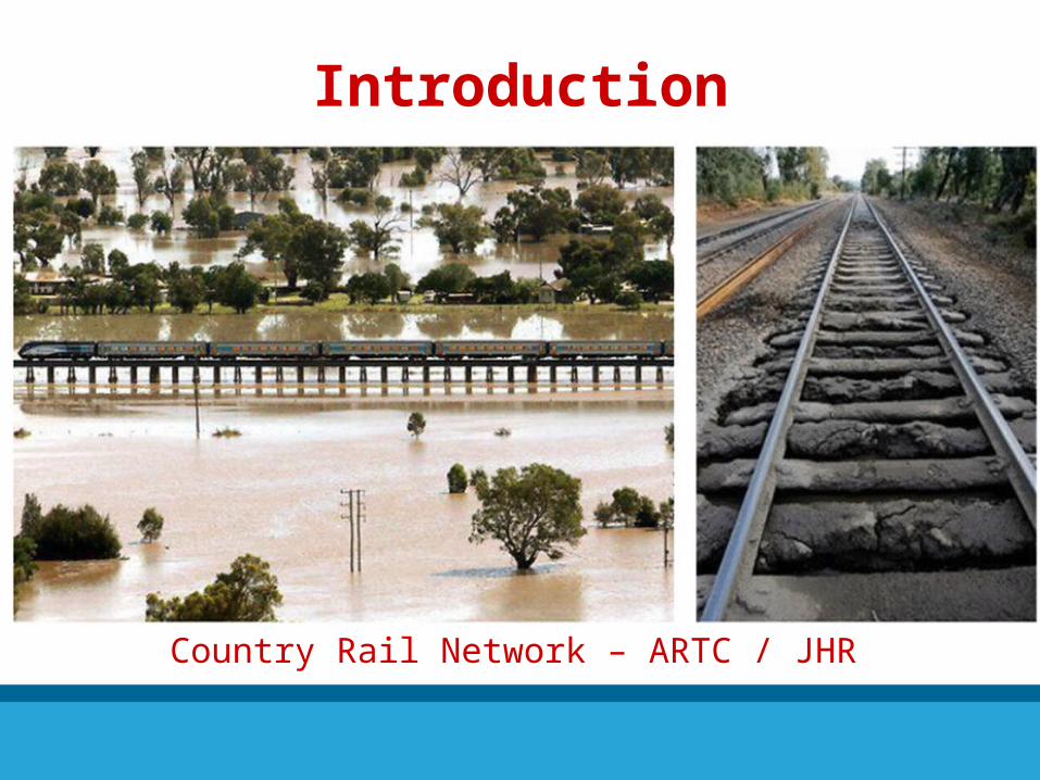
Introduction
Country Rail Network – ARTC / JHR
RAIL CRC
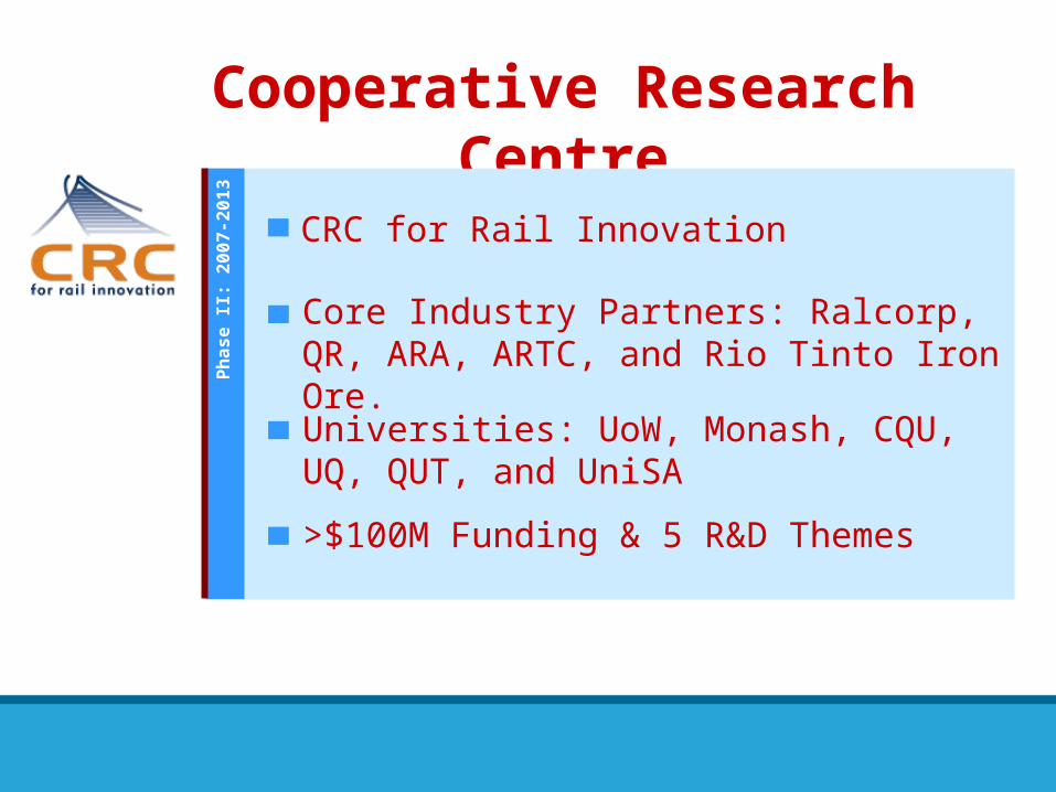
Cooperative Research Centre
CRC for Rail InnovationP
hase I
I: 2
00
7-2
01
3
Core Industry Partners: Ralcorp, QR, ARA, ARTC, and Rio Tinto Iron Ore.
Universities: UoW, Monash, CQU, UQ, QUT, and UniSA
>$100M Funding & 5 R&D Themes
RAIL CRC
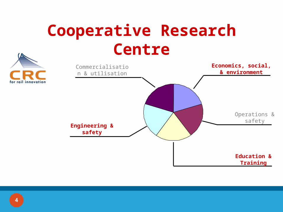
Cooperative Research Centre
Economics, social, & environment
Operations & safety
Education & Training
Engineering & safety
Commercialisation & utilisation
4
RAIL CRC
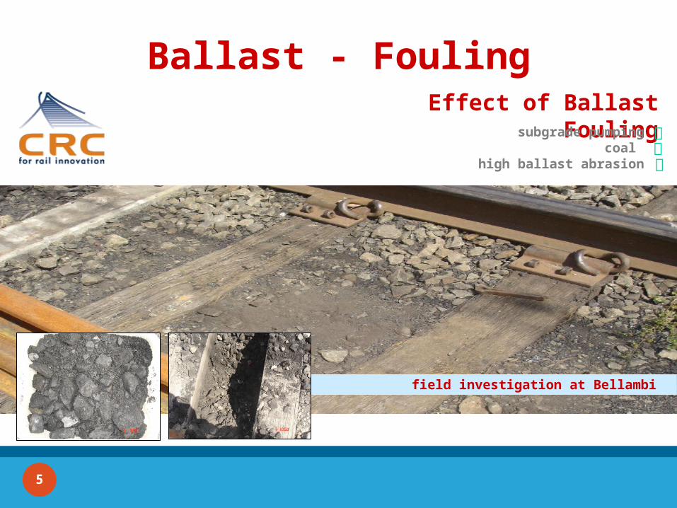
Ballast - FoulingEffect of Ballast Fouling
subgrade pumpingcoal
high ballast abrasion
field investigation at Bellambi
5
RAIL CRC
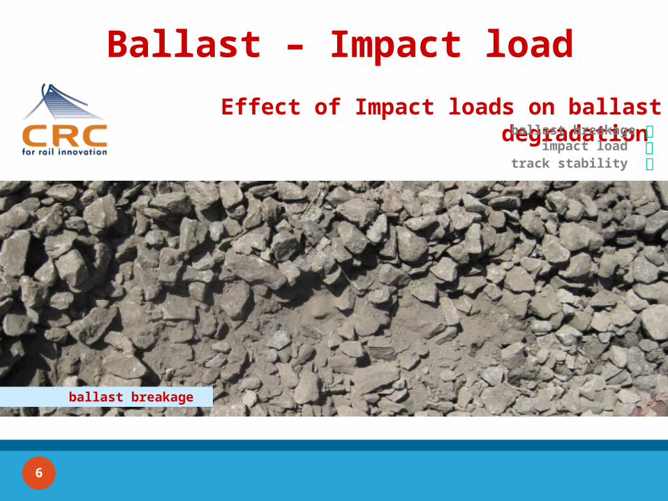
Ballast – Impact load
Effect of Impact loads on ballast degradation ballast breakage
impact load
track stability
ballast breakage
6
RAIL CRC
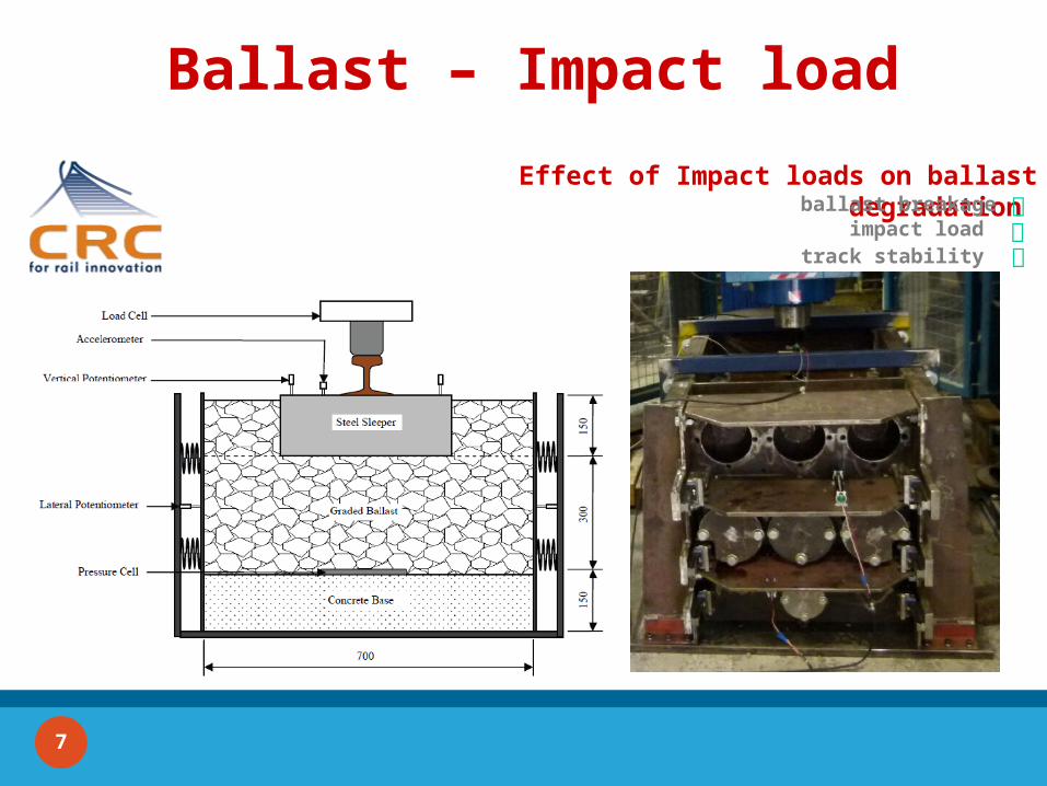
Ballast – Impact load
Effect of Impact loads on ballast degradation ballast breakage
impact load
track stability
ballast breakage
7
RAIL CRC
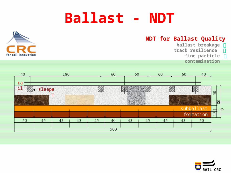
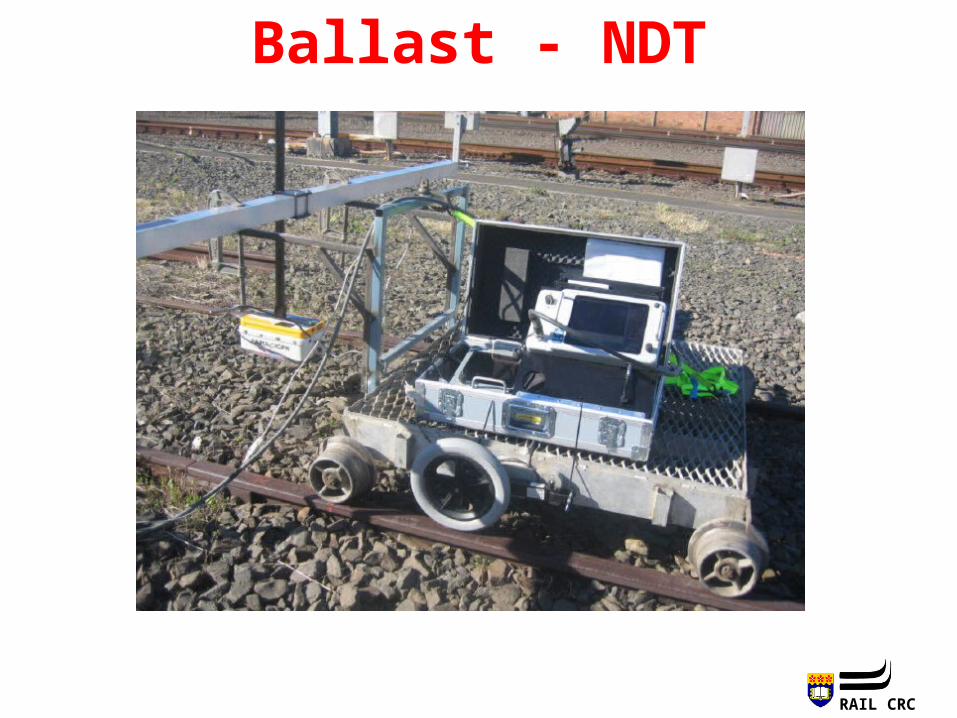
Ballast - NDTNDT for Ballast Quality
ballast breakagetrack resilience
fine particle contamination
ballast layer
subballastformation
rail
sleeper
RAIL CRC
Ballast - NDT
RAIL CRC
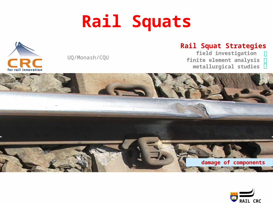
Rail SquatsRail Squat Strategies
field investigation
UQ/Monash/CQU finite element analysismetallurgical studies
damage of components
RAIL CRC
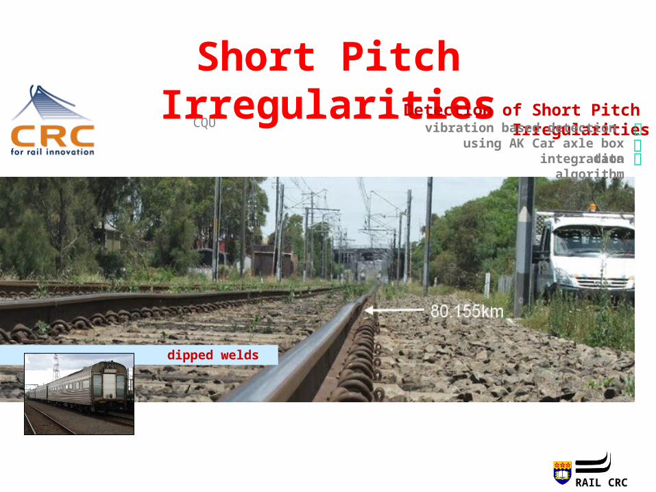
Short Pitch Irregularities
CQU
dipped welds
Detection of Short Pitch Irregularitiesvibration based detection
using AK Car axle box dataintegration algorithm
RAIL CRC
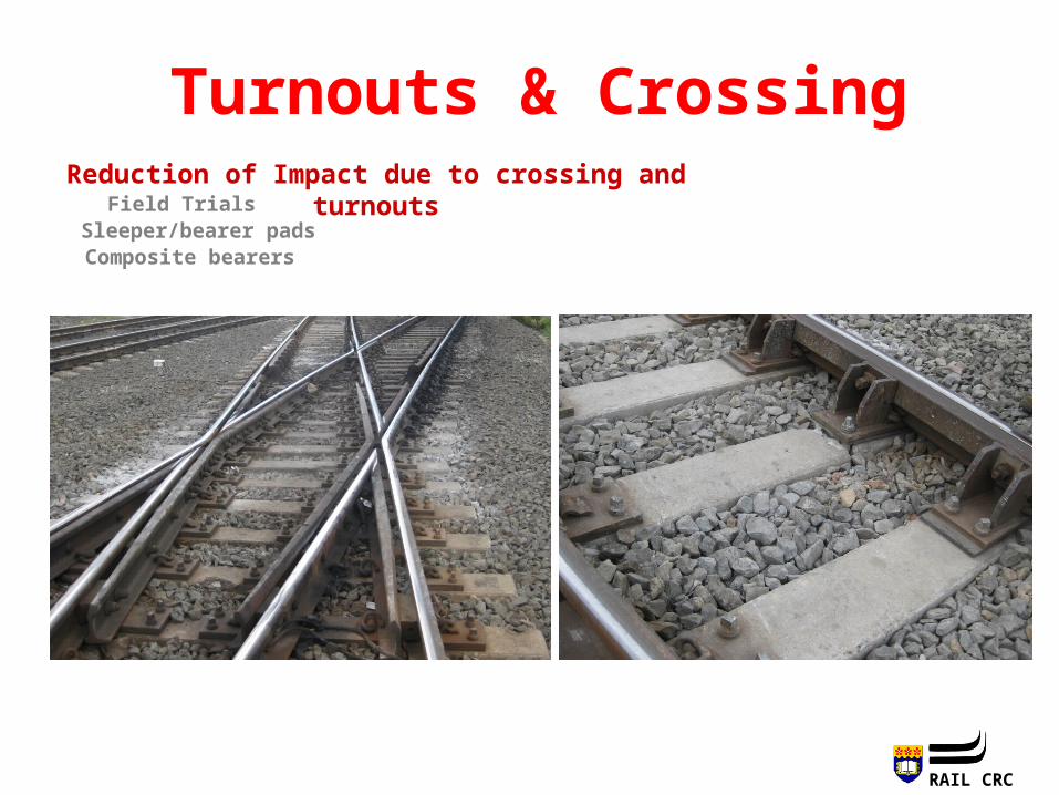
Turnouts & CrossingReduction of Impact due to crossing and turnouts
Field Trials Sleeper/bearer padsComposite bearers
RAIL CRC
13
Concrete Sleepers Projects
Innovative/Automated Track Maintenance and Upgrading Technologies
Dynamic analysis of track and the assessment of its capacity with particular
reference to concrete sleepers
Key Industry Partners
I ntroduction RAIL CRC 13
RAIL CRC
14
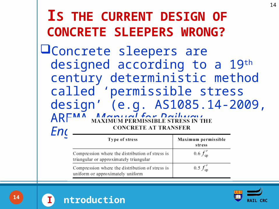
Concrete sleepers are designed according to a 19th century deterministic method called ‘permissible stress design’ (e.g. AS1085.14-2009, AREMA Manual for Railway Engineering (2010).
IS THE CURRENT DESIGN OF CONCRETE SLEEPERS WRONG?
RAIL CRC I ntroduction14
RAIL CRC
15
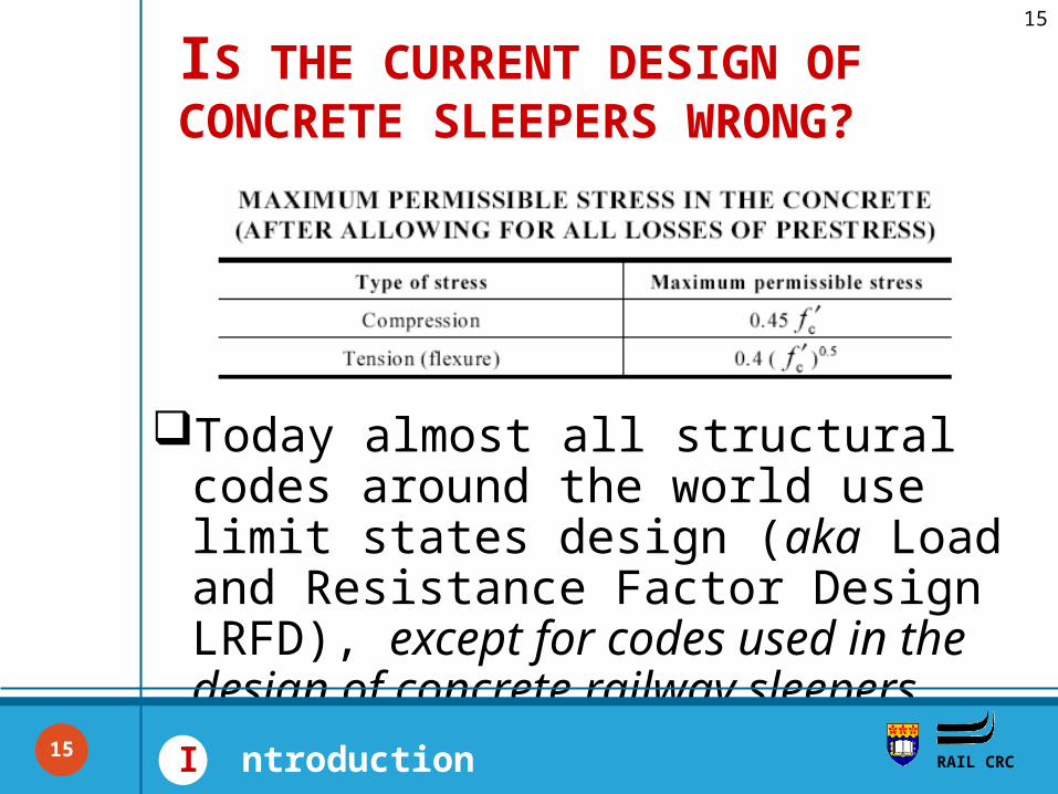
Today almost all structural codes around the world use limit states design (aka Load and Resistance Factor Design LRFD), except for codes used in the design of concrete railway sleepers.
IS THE CURRENT DESIGN OF CONCRETE SLEEPERS WRONG?
RAIL CRC I ntroduction15
RAIL CRC
16
There is a widespread perception in the railway industry that concrete sleepers have unused reserves of strength.
E.g., sleepers are generally replaced only because of non-design factors such as serious damage due to train derailment or inappropriate materials in the concrete mix or manufacturing faults.
IS THE CURRENT DESIGN OF CONCRETE SLEEPERS WRONG?
RAIL CRC I ntroduction16
RAIL CRC
17
If concrete sleepers have unused reserve strength, increases in axle loads & train speeds may not, for example, need sleepers to be replaced with heavier ones.
The saving in expenditure around AU$100,000 per km of track could be achieved if the 22t sleepers in that section of track are found to not need replacing with higher rated sleepers.
IS THE CURRENT DESIGN OF CONCRETE SLEEPERS WRONG?
RAIL CRC I ntroduction17
RAIL CRC
18
The current design approach is not wrong, but there is clearly a need for a method of designing and rating of concrete sleepers that is more rational than permissible stress design and which allows for the inherent variability of strength and of applied loads.
Development of the framework for designing concrete sleepers using limit states approach is discussed in this presentation.
IS THE CURRENT DESIGN OF CONCRETE SLEEPERS WRONG?
RAIL CRC I ntroduction18
RAIL CRC
19
Limit States Design Framework for Prestressed Concrete Sleepers
19
RAIL CRC
20
RAIL CRC L imit states design
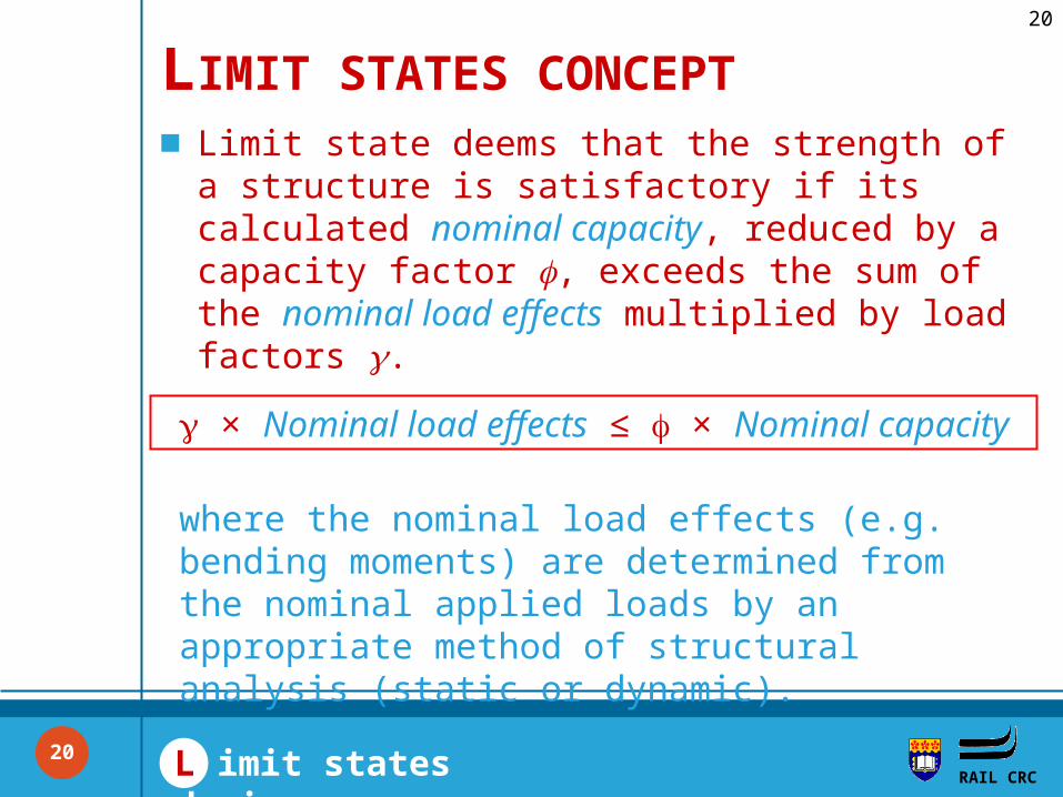
Limit state deems that the strength of a structure is satisfactory if its calculated nominal capacity, reduced by a capacity factor , exceeds the sum of the nominal load effects multiplied by load factors .
LIMIT STATES CONCEPT
× Nominal load effects ≤ × Nominal capacity
where the nominal load effects (e.g. bending moments) are determined from the nominal applied loads by an appropriate method of structural analysis (static or dynamic).
20
RAIL CRC
21
RAIL CRC L imit states design
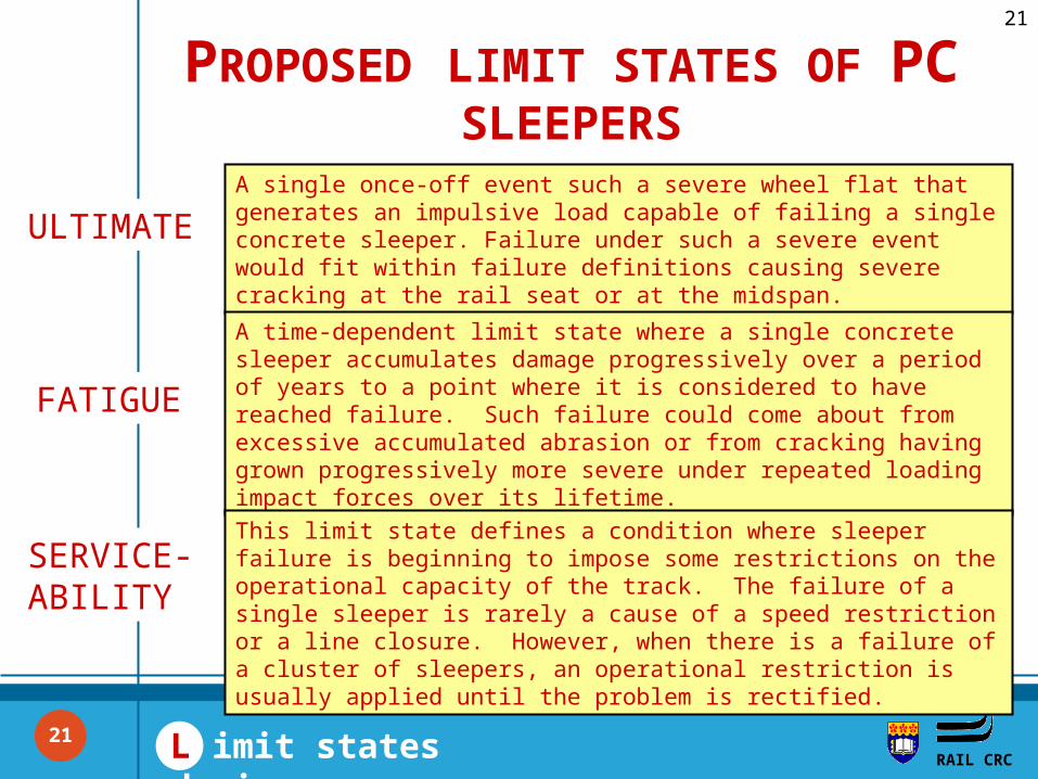
A single once-off event such a severe wheel flat that generates an impulsive load capable of failing a single concrete sleeper. Failure under such a severe event would fit within failure definitions causing severe cracking at the rail seat or at the midspan.
PROPOSED LIMIT STATES OF PC SLEEPERS
A time-dependent limit state where a single concrete sleeper accumulates damage progressively over a period of years to a point where it is considered to have reached failure. Such failure could come about from excessive accumulated abrasion or from cracking having grown progressively more severe under repeated loading impact forces over its lifetime.
This limit state defines a condition where sleeper failure is beginning to impose some restrictions on the operational capacity of the track. The failure of a single sleeper is rarely a cause of a speed restriction or a line closure. However, when there is a failure of a cluster of sleepers, an operational restriction is usually applied until the problem is rectified.
ULTIMATE
FATIGUE
SERVICE-ABILITY
21
RAIL CRC
22
RAIL CRC
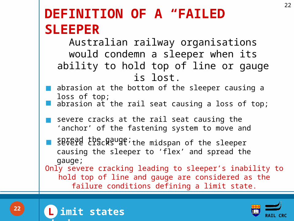
DEFINITION OF A “FAILED” SLEEPER
abrasion at the bottom of the sleeper causing a loss of top;
Australian railway organisations would condemn a sleeper when its ability to hold
top of line or gauge is lost.
abrasion at the rail seat causing a loss of top;
severe cracks at the rail seat causing the ‘anchor’ of the
fastening system to move and spread the gauge; severe cracks at the midspan of the sleeper causing the sleeper to ‘flex’ and spread the gauge;
Only severe cracking leading to sleeper’s inability to hold top of line and gauge are considered as the failure conditions defining
a limit state.
L imit states design22
RAIL CRC
Limit States Design and In-track Loads
23
RAIL CRC
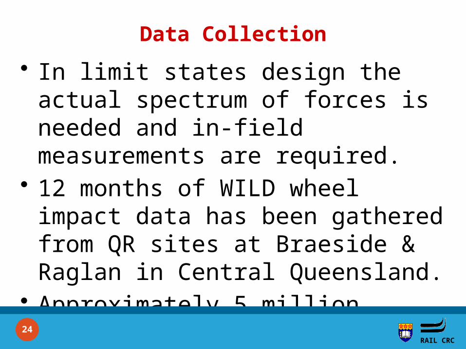
Data Collection
• In limit states design the actual spectrum of forces is needed and in-field measurements are required.
• 12 months of WILD wheel impact data has been gathered from QR sites at Braeside & Raglan in Central Queensland.
• Approximately 5 million measurements of impacts means data is statistically robust.
RAIL CRC 24
RAIL CRC
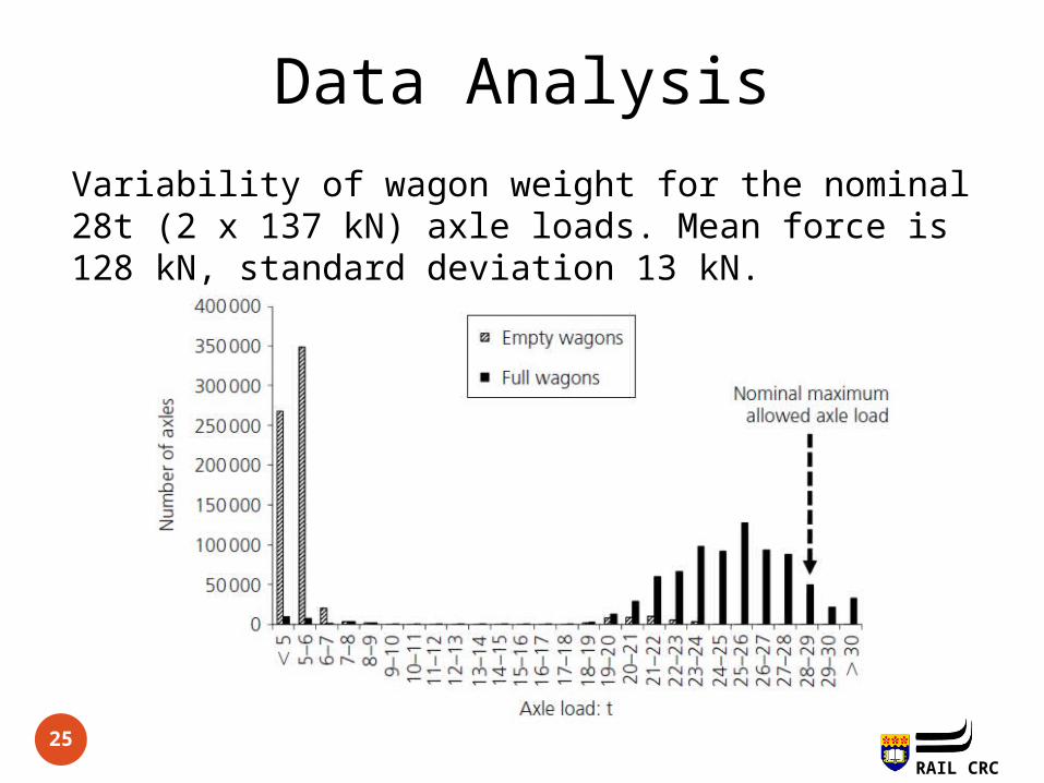
Data Analysis
25
Variability of wagon weight for the nominal 28t (2 x 137 kN) axle loads. Mean force is 128 kN, standard deviation 13 kN.
RAIL CRC
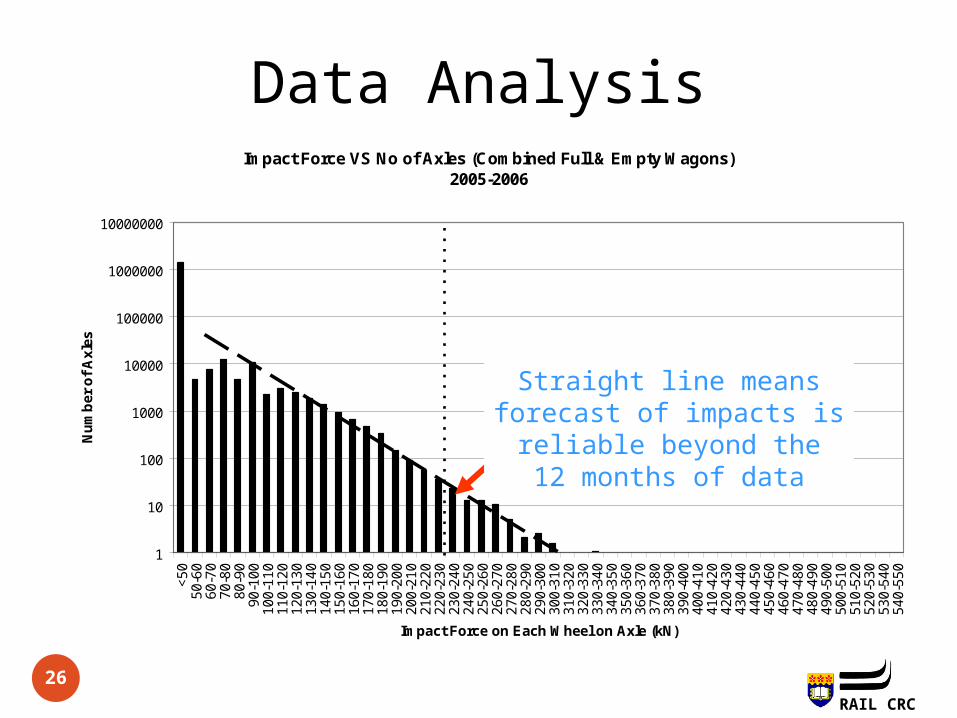
Data AnalysisImpact Force VS No of Axles (Combined Full & Empty Wagons)
2005-2006
1
10
100
1000
10000
100000
1000000
10000000
<50
50-6
060
-70
70-8
080
-90
90-1
0010
0-11
011
0-12
012
0-13
013
0-14
014
0-15
015
0-16
016
0-17
017
0-18
018
0-19
019
0-20
020
0-21
021
0-22
022
0-23
023
0-24
024
0-25
025
0-26
026
0-27
027
0-28
028
0-29
029
0-30
030
0-31
031
0-32
032
0-33
033
0-34
034
0-35
035
0-36
036
0-37
037
0-38
038
0-39
039
0-40
040
0-41
041
0-42
042
0-43
043
0-44
044
0-45
045
0-46
046
0-47
047
0-48
048
0-49
049
0-50
050
0-51
051
0-52
052
0-53
053
0-54
054
0-55
0
Impact Force on Each Wheel on Axle (kN)
Nu
mb
er o
f A
xles
Allowable Impact Force(Code of Practice)
Straight line meansforecast of impacts isreliable beyond the12 months of data
26
RAIL CRC
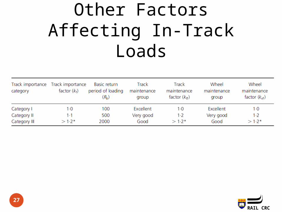
Other Factors Affecting In-Track Loads
27
RAIL CRC
28
Experimental Investigation of Dynamic Ultimate Capacities of
Prestressed Concrete Sleepers for Limit States Design
28
RAIL CRC
29
T esting RAIL CRC
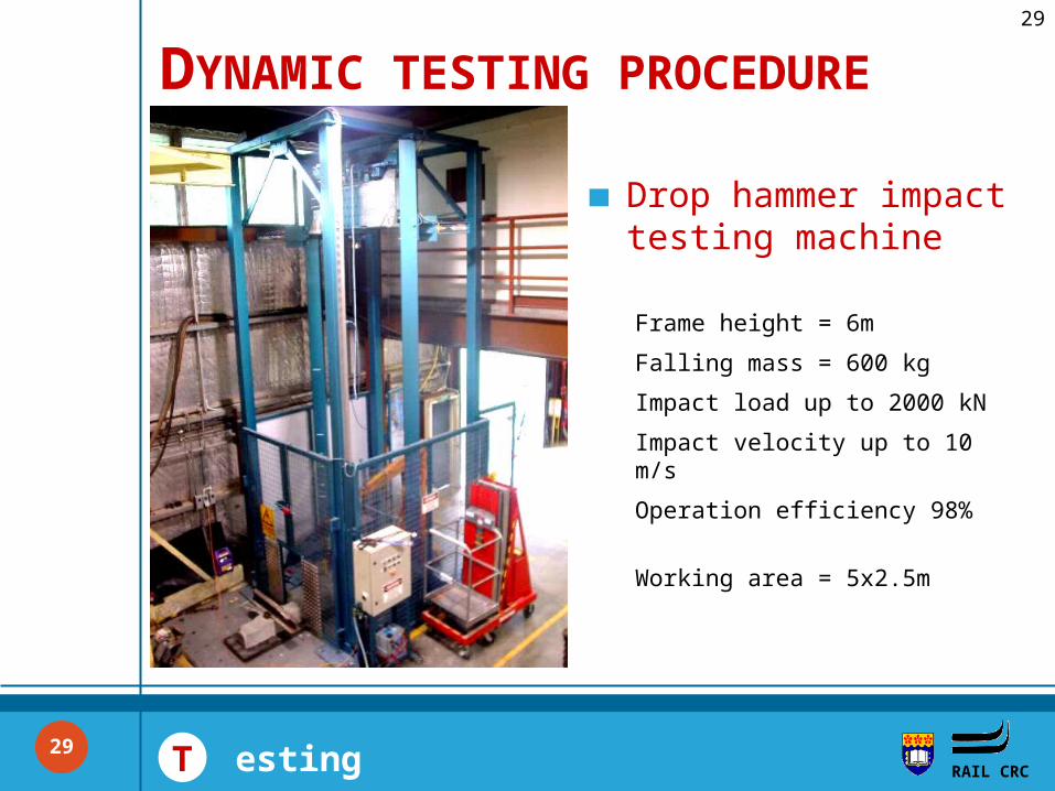
DYNAMIC TESTING PROCEDURE
Drop hammer impact testing machine
Frame height = 6m
Falling mass = 600 kg
Impact load up to 2000 kN
Impact velocity up to 10 m/s
Operation efficiency 98%
Working area = 5x2.5m
29
RAIL CRC
30
RAIL CRC T esting
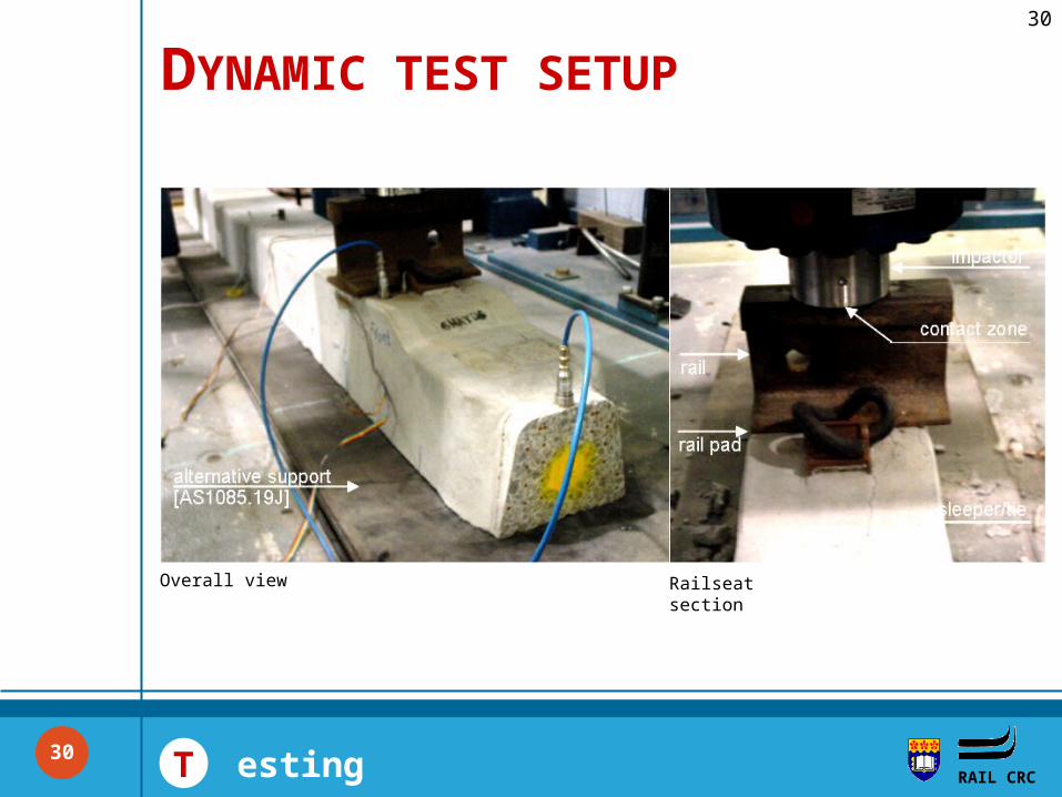
DYNAMIC TEST SETUP
Railseat sectionOverall view
30
RAIL CRC
31
RAIL CRC T esting
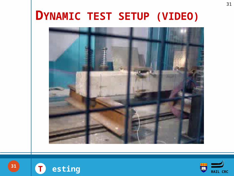
DYNAMIC TEST SETUP (VIDEO)
31
RAIL CRC
32
RAIL CRC T esting
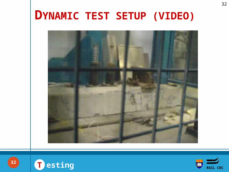
DYNAMIC TEST SETUP (VIDEO)
32
RAIL CRC
33
RAIL CRC T esting
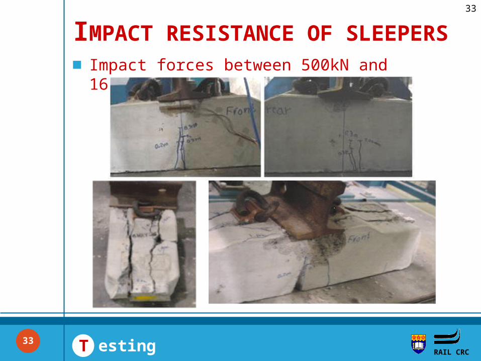
Impact forces between 500kN and 1600kN
IMPACT RESISTANCE OF SLEEPERS
33
RAIL CRC
34
RAIL CRC T esting
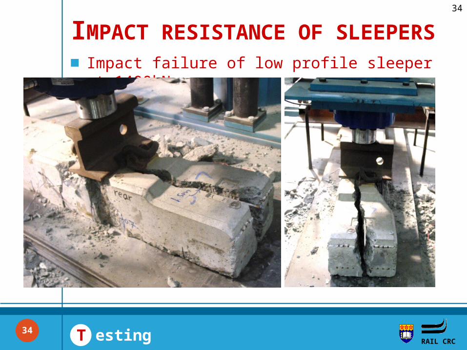
Impact failure of low profile sleeper at 1400kN
IMPACT RESISTANCE OF SLEEPERS
34
RAIL CRC
35
RAIL CRC T esting
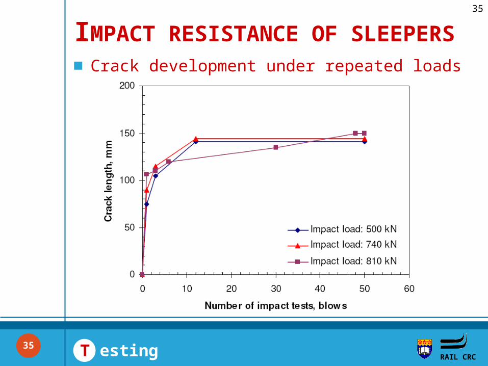
Crack development under repeated loads
IMPACT RESISTANCE OF SLEEPERS
35
RAIL CRC
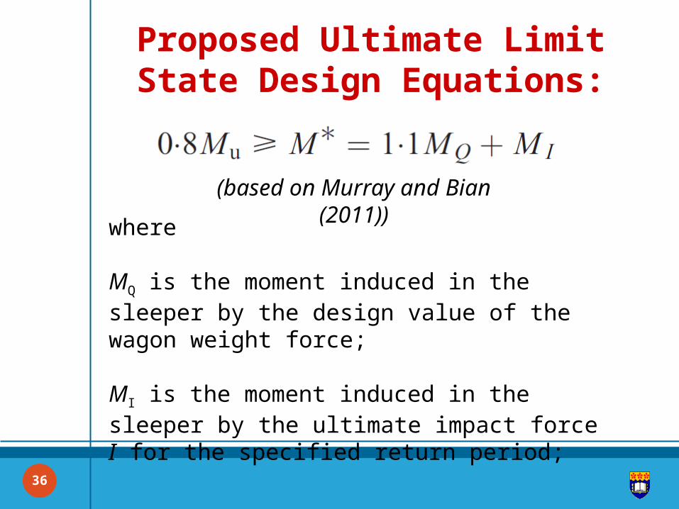
Proposed Ultimate Limit State Design Equations:
where
MQ is the moment induced in the sleeper by the design value of the wagon weight force;
MI is the moment induced in the sleeper by the ultimate impact force I for the specified return period;
36
(based on Murray and Bian (2011))
RAIL CRC
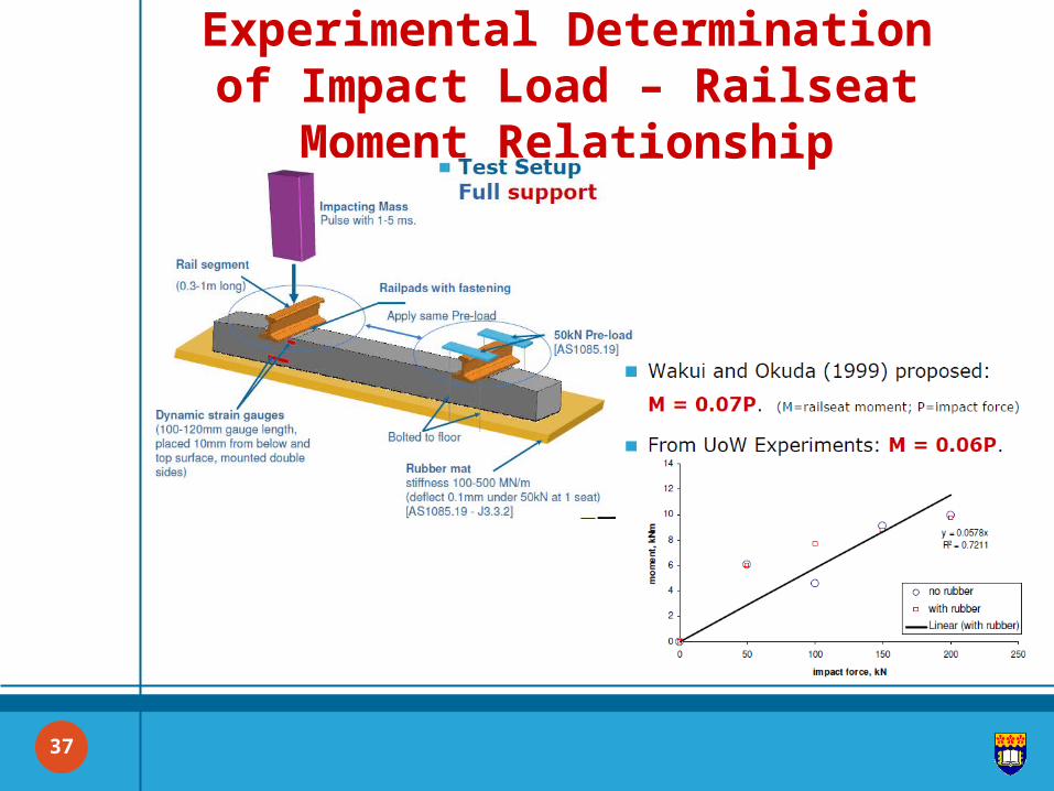
Experimental Determination of Impact Load – Railseat Moment Relationship
37
RAIL CRC
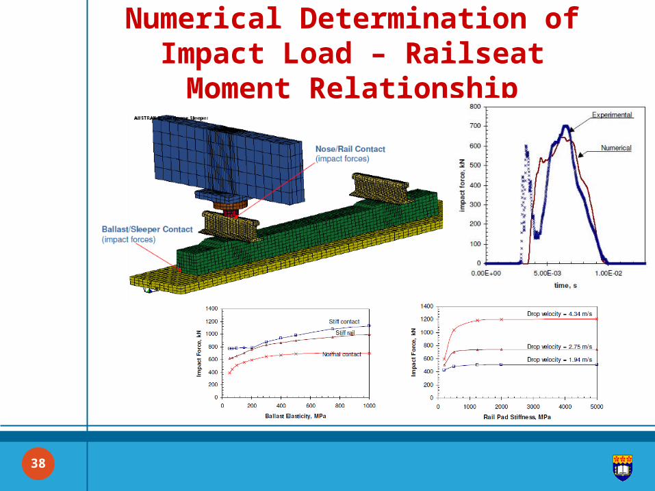
Numerical Determination of Impact Load – Railseat Moment Relationship
38
RAIL CRC
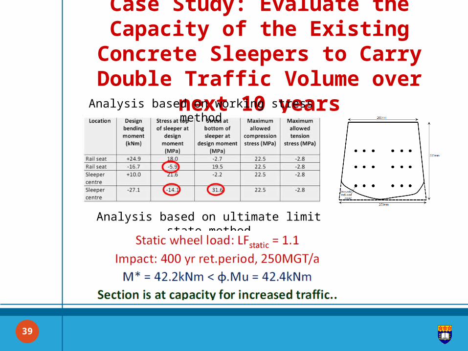
Case Study: Evaluate the Capacity of the Existing Concrete Sleepers to Carry
Double Traffic Volume over next 10 years
39
Analysis based on working stress method
Analysis based on ultimate limit state method
RAIL CRC
40
C onclusions RAIL CRC
CONCLUSIONS
The proposed methodology has been successfully applied to the problems involving increased traffic volume and increased axle loads where the untapped reserve capacity allowed to not replacing the existing concrete sleepers with higher rated sleepers.
Extensive investigations at UoW within the framework of the Rail-CRC have addressed the spectrum and magnitudes of dynamic forces, the reserve capacity of typical PC sleepers, and the development of a new limit states design concept.
40
RAIL CRC
41
Q &A
Thank you for your attention
Questions
& Answers