rail defect detection under shelling - railway research · rail defect detection under shelling...
TRANSCRIPT
1
Rail Defect Detection Under Shelling
Thomas R. Hay1, D. Robert Hay1, Don Plotkin2, C.M. Lee3, Joseph L. Rose3, WavesInSolids LLC1, Madeira Beach, Fl. USA, Federal Railroad Administration2, Washington DC, USA, The Pennsylvania
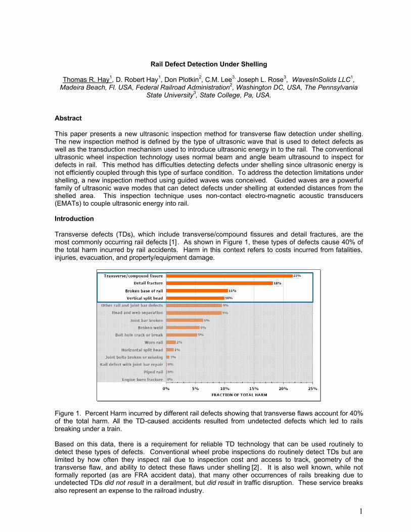
State University3, State College, Pa, USA. Abstract This paper presents a new ultrasonic inspection method for transverse flaw detection under shelling. The new inspection method is defined by the type of ultrasonic wave that is used to detect defects as well as the transduction mechanism used to introduce ultrasonic energy in to the rail. The conventional ultrasonic wheel inspection technology uses normal beam and angle beam ultrasound to inspect for defects in rail. This method has difficulties detecting defects under shelling since ultrasonic energy is not efficiently coupled through this type of surface condition. To address the detection limitations under shelling, a new inspection method using guided waves was conceived. Guided waves are a powerful family of ultrasonic wave modes that can detect defects under shelling at extended distances from the shelled area. This inspection technique uses non-contact electro-magnetic acoustic transducers (EMATs) to couple ultrasonic energy into rail. Introduction Transverse defects (TDs), which include transverse/compound fissures and detail fractures, are the most commonly occurring rail defects [1] . As shown in Figure 1, these types of defects cause 40% of the total harm incurred by rail accidents. Harm in this context refers to costs incurred from fatalities, injuries, evacuation, and property/equipment damage.
Figure 1. Percent Harm incurred by different rail defects showing that transverse flaws account for 40% of the total harm. All the TD-caused accidents resulted from undetected defects which led to rails breaking under a train. Based on this data, there is a requirement for reliable TD technology that can be used routinely to detect these types of defects. Conventional wheel probe inspections do routinely detect TDs but are limited by how often they inspect rail due to inspection cost and access to track, geometry of the transverse flaw, and ability to detect these flaws under shelling [2] . It is also well known, while not formally reported (as are FRA accident data), that many other occurrences of rails breaking due to undetected TDs did not result in a derailment, but did result in traffic disruption. These service breaks also represent an expense to the railroad industry.
2
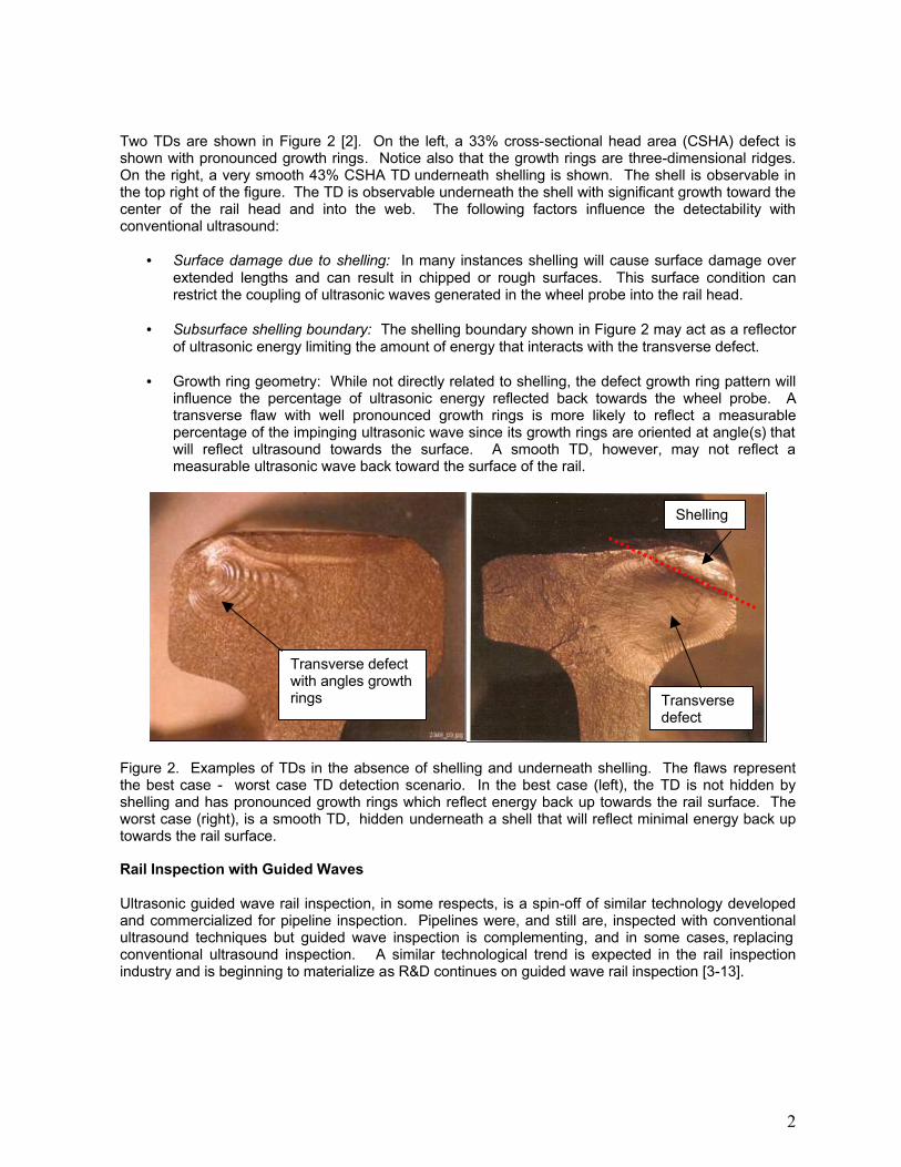
Two TDs are shown in Figure 2 [2]. On the left, a 33% cross-sectional head area (CSHA) defect is shown with pronounced growth rings. Notice also that the growth rings are three-dimensional ridges. On the right, a very smooth 43% CSHA TD underneath shelling is shown. The shell is observable in the top right of the figure. The TD is observable underneath the shell with significant growth toward the center of the rail head and into the web. The following factors influence the detectability with conventional ultrasound:
• Surface damage due to shelling: In many instances shelling will cause surface damage over extended lengths and can result in chipped or rough surfaces. This surface condition can restrict the coupling of ultrasonic waves generated in the wheel probe into the rail head.
• Subsurface shelling boundary: The shelling boundary shown in Figure 2 may act as a reflector
of ultrasonic energy limiting the amount of energy that interacts with the transverse defect.
• Growth ring geometry: While not directly related to shelling, the defect growth ring pattern will influence the percentage of ultrasonic energy reflected back towards the wheel probe. A transverse flaw with well pronounced growth rings is more likely to reflect a measurable percentage of the impinging ultrasonic wave since its growth rings are oriented at angle(s) that will reflect ultrasound towards the surface. A smooth TD, however, may not reflect a measurable ultrasonic wave back toward the surface of the rail.
Figure 2. Examples of TDs in the absence of shelling and underneath shelling. The flaws represent the best case - worst case TD detection scenario. In the best case (left), the TD is not hidden by shelling and has pronounced growth rings which reflect energy back up towards the rail surface. The worst case (right), is a smooth TD, hidden underneath a shell that will reflect minimal energy back up towards the rail surface. Rail Inspection with Guided Waves Ultrasonic guided wave rail inspection, in some respects, is a spin-off of similar technology developed and commercialized for pipeline inspection. Pipelines were, and still are, inspected with conventional ultrasound techniques but guided wave inspection is complementing, and in some cases, replacing conventional ultrasound inspection. A similar technological trend is expected in the rail inspection industry and is beginning to materialize as R&D continues on guided wave rail inspection [3-13].
Shelling
Transverse defect
Transverse defect with angles growth rings

3
Conventional ultrasonic testing transmits a finite bulk ultrasonic pulse through materials to test for material loss and mechanical integrity. Guided waves are another family of wave modes that may be used to inspect structures with well-defined boundaries including rail, pipe, rod, plates, and layered media. Guided waves include Lamb waves, Rayleigh waves, Sezawa waves and Love waves. Figure 3Figure 3 shows a FEM simulation of guided wave inspection of rail.
(a) t = 19 㯀sec (b) t = 144 㯀sec (c) t = 186 㯀sec
(d) t = 231㯀sec (e) t = 285㯀sec (f) t = 330㯀sec
Figure 3. FEM wave propagation model showing guided wave scattering pattern from a 40 mm deep simulated TD underneath shelling. Defect Detection Under Shelling CN North America’s Rail Defect Manual defines shelled rail as [14]:
• A progressive horizontal separation which may crack out at any level on the gauge side, generally, at the upper corner. It extends longitudinally not as a true horizontal or vertical crack, but at an angle related to the amount of rail wear.
It appears in the track as:
• Dark spots irregularly spaced on the gauge side of the running surface, sometimes with crack-out.
• Longitudinal separations at one or more levels in the upper gauge corner, with discoloration from bleeding.
• If the rail is turned, shelled spots will appear on the field side with an irregular overhanging lip of metal. This should not be confused with Flowed Rail.
The manual also warns that detail fractures may also occur from shelled rail.
Defect
Reflected wave
Incident wave
Scattering Reflected wave Transmitted wave
4
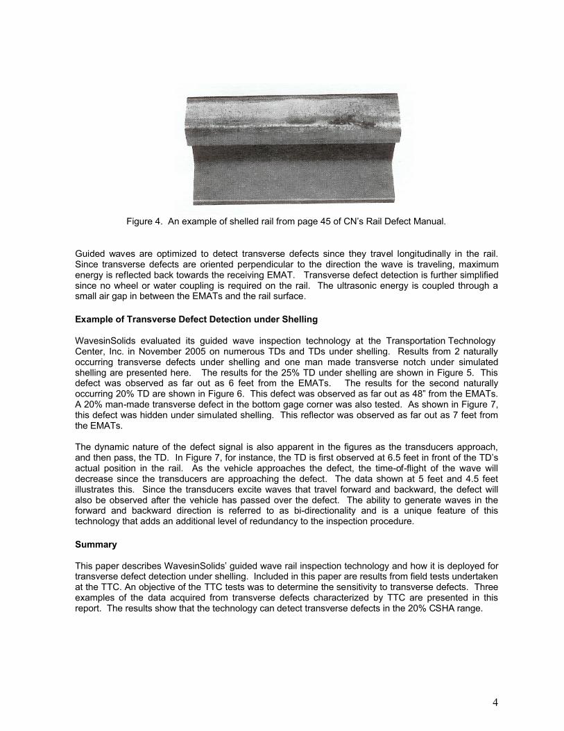
Figure 4. An example of shelled rail from page 45 of CN’s Rail Defect Manual.
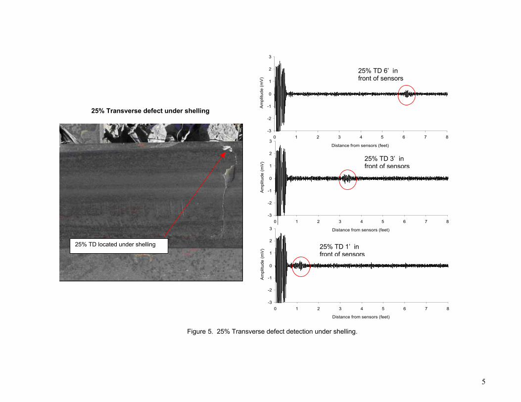
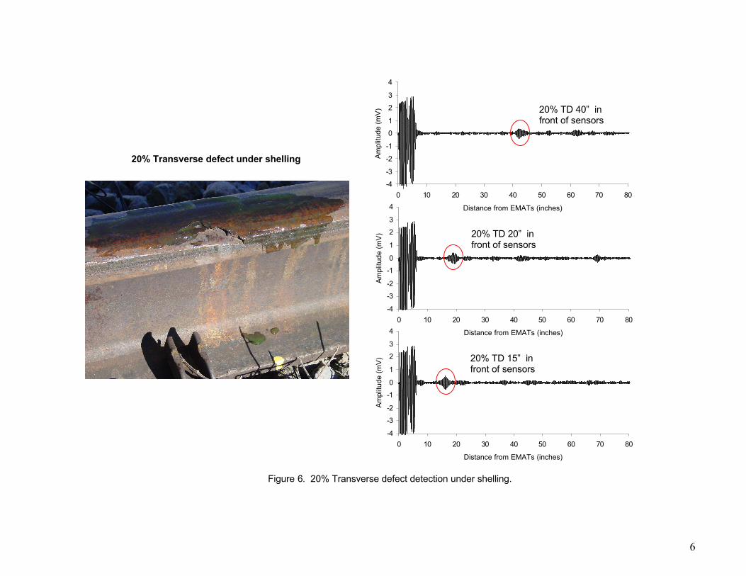
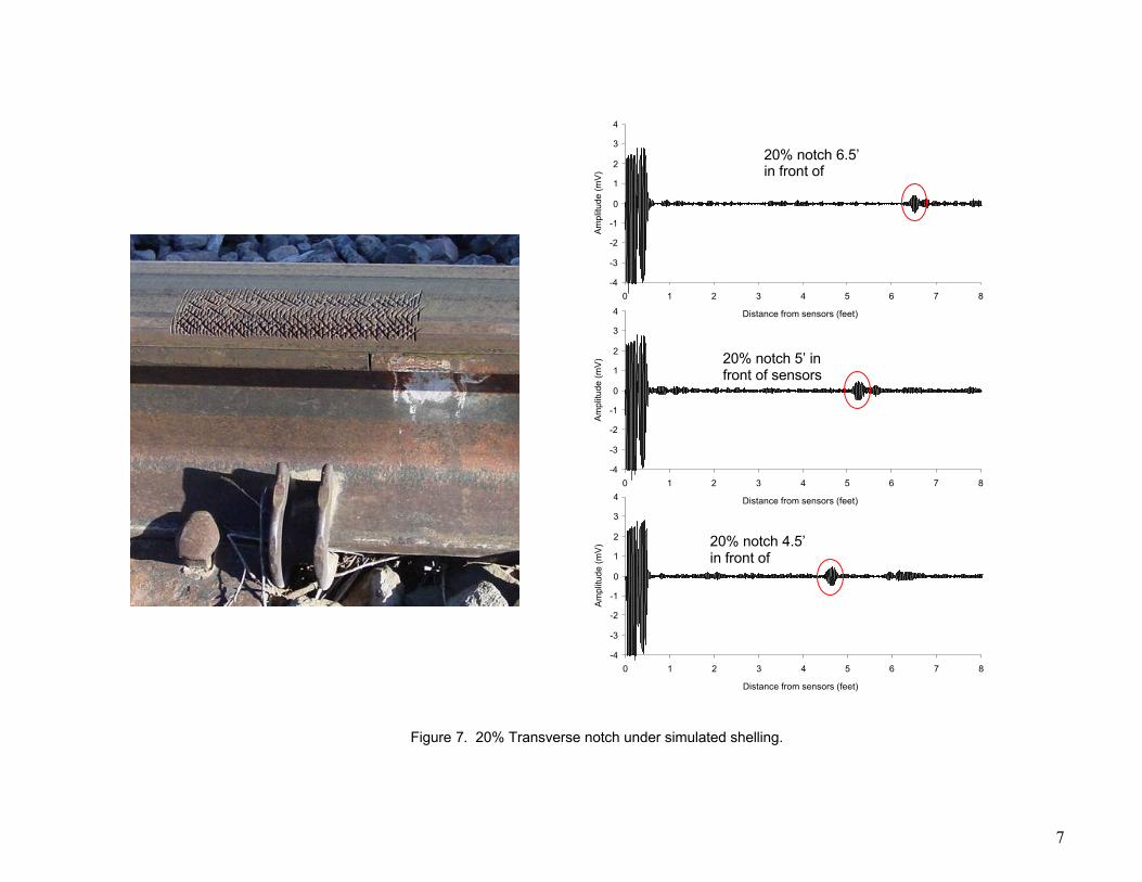
Guided waves are optimized to detect transverse defects since they travel longitudinally in the rail. Since transverse defects are oriented perpendicular to the direction the wave is traveling, maximum energy is reflected back towards the receiving EMAT. Transverse defect detection is further simplified since no wheel or water coupling is required on the rail. The ultrasonic energy is coupled through a small air gap in between the EMATs and the rail surface. Example of Transverse Defect Detection under Shelling WavesinSolids evaluated its guided wave inspection technology at the Transportation Technology Center, Inc. in November 2005 on numerous TDs and TDs under shelling. Results from 2 naturally occurring transverse defects under shelling and one man made transverse notch under simulated shelling are presented here. The results for the 25% TD under shelling are shown in Figure 5. This defect was observed as far out as 6 feet from the EMATs. The results for the second naturally occurring 20% TD are shown in Figure 6. This defect was observed as far out as 48” from the EMATs. A 20% man-made transverse defect in the bottom gage corner was also tested. As shown in Figure 7, this defect was hidden under simulated shelling. This reflector was observed as far out as 7 feet from the EMATs. The dynamic nature of the defect signal is also apparent in the figures as the transducers approach, and then pass, the TD. In Figure 7, for instance, the TD is first observed at 6.5 feet in front of the TD’s actual position in the rail. As the vehicle approaches the defect, the time-of-flight of the wave will decrease since the transducers are approaching the defect. The data shown at 5 feet and 4.5 feet illustrates this. Since the transducers excite waves that travel forward and backward, the defect will also be observed after the vehicle has passed over the defect. The ability to generate waves in the forward and backward direction is referred to as bi-directionality and is a unique feature of this technology that adds an additional level of redundancy to the inspection procedure. Summary This paper describes WavesinSolids’ guided wave rail inspection technology and how it is deployed for transverse defect detection under shelling. Included in this paper are results from field tests undertaken at the TTC. An objective of the TTC tests was to determine the sensitivity to transverse defects. Three examples of the data acquired from transverse defects characterized by TTC are presented in this report. The results show that the technology can detect transverse defects in the 20% CSHA range.
5
Figure 5. 25% Transverse defect detection under shelling.
25% TD located under shelling
25% Transverse defect under shelling
-3
-2
-1
0
1
2
3
0 1 2 3 4 5 6 7 8
Distance from sensors (feet)
Am
plitu
de (m
V)
25% TD 6’ in front of sensors
-3
-2
-1
0
1
2
3
0 1 2 3 4 5 6 7 8
Distance from sensors (feet)
Am
plitu
de (m
V) 25% TD 3’ in
front of sensors
-3
-2
-1
0
1
2
3
0 1 2 3 4 5 6 7 8
Distance from sensors (feet)
Am
plitu
de (m
V) 25% TD 1’ in
front of sensors
6
Figure 6. 20% Transverse defect detection under shelling.
-4
-3
-2
-1
0
1
2
3
4
0 10 20 30 40 50 60 70 80
Distance from EMATs (inches)
Ampl
itude
(mV)
-4
-3
-2
-1
0
1
2
3
4
0 10 20 30 40 50 60 70 80
Distance from EMATs (inches)
Ampl
itude
(mV)
-4
-3
-2
-1
0
1
2
3
4
0 10 20 30 40 50 60 70 80
Distance from EMATs (inches)
Ampl
itude
(mV)
20% Transverse defect under shelling
20% TD 15” in front of sensors
20% TD 20” in front of sensors
20% TD 40” in front of sensors
7
Figure 7. 20% Transverse notch under simulated shelling.
-4
-3
-2
-1
0
1
2
3
4
0 1 2 3 4 5 6 7 8
Distance from sensors (feet)
Am
plitu
de (m
V)
-4
-3
-2
-1
0
1
2
3
4
0 1 2 3 4 5 6 7 8
Distance from sensors (feet)
Am
plitu
de (m
V)
-4
-3
-2
-1
0
1
2
3
4
0 1 2 3 4 5 6 7 8
Distance from sensors (feet)
Am
plitu
de (m
V)
20% notch 6.5’ in front of
20% notch 5’ in front of sensors
20% notch 4.5’ in front of
8
References 1. Gordon, J. “Structural Integrity Detection Needs in the Railroad Industry”, Volpe National
Transportations System Center, Cambridge, Ma, (See also http://safetydata.fra.dot.gov). 2. Flaw Characterization of Rail Service Failures, Report No. R-963 AAR Research Report July
2003. 3. McNamara, J and Lanza di Scalea, F, "Improvements in Non-contact UT Testing of Rails by
the Discrete Wavelet Transform," Materials Evaluation, 62(3), 2004. 4. Lanza di Scalea, F. and McNamara, J., "Measuring High-frequency Waves Propagating in
Railroad Tracks by Joint Time-Frequency Analysis," Journal of Sound and Vibration, in press, 2004.
5. Lanza di Scalea, F. and McNamara, J., "Ultrasonic NDE of Railroad Tracks: Air-coupled Cross-sectional Inspection and Long-range Inspection," Insight - Non-destructive Testing and Condition Monitoring, EURO Issue on NDT in the Rail Industry, Vol. 45, No. 6, pp. 394-401, 2003.
6. McNamara, J. and Lanza di Scalea, F., "Air-coupled Ultrasonic Testing of Railroad Rails," Materials Evaluation, 60(12), pp. 1431-1437, 2002.
7. Lanza di Scalea, F, "Advances in Non-contact UT Inspection of Railroad Tracks," Experimental Techniques, 24(5), pp. 23-26, 2000.
8. Dixon S, Edwards RS and Jian,X, Inspection of the railtrack head surfaces using electromagnetic acoustic transducers, Insight, 46, pp326-330, 2004.
9. Edwards RS, Dixon S and Jian X, Enhancement of the Rayleigh wave signal at surface defects, J Phys D, 37, pp2291-2297, 2004
10. Edwards RS, Dixon S and Jian X, Non-contact ultrasonic characterisation of defects using EMATs, to be published in Rev Prog in QNDE 2004, vol. 24
11. Hesse, D. and Cawley. P., 'The potential of ultrasonic surface waves for rail inspection'. In D. O. Thompson and D. E. Chimenti editors. Review of progress in quantitative NDE (American Institute of Physics), in press.
12. Wilcox, P., Alleyne, D.N., Pavlakovic, B., Evans, M.J., Vine, K., Cawley, P. and Lowe, M.J.S. 'Long range inspection of rail using guided waves', Proc Railway Engineering - 2002, London, 3-4 July, 2002. Similar paper in Review of Progress in Quantitative NDE, Vol 22, DO Thompson and DE Chimenti (eds), American Institute of Physics, pp236-243, 2003.
13. United States Patent 6,148,672 Cawley , et al. November 21, 2000 14. Rail Defect Reference Manual, CN Engineering Asset Management, January 1998.