railcommand digital wireless throttle system installation
TRANSCRIPT

Railcommand Digital Wireless Throttle SystemInstallation and Setup Guide
Quick Start Procedure
1. Install four AAA batteries into throttle.
2. Set desired frequency inside throttle with SW2. Frequency 0 is the default setting from the factory with all switches on.
3. Reinstall throttle in case.
4. Attach antenna - finger tight.
5. Attach antenna to RX900 receiver - finger tight. Take care not to strip threads.
6. Set desired mode - scan mode is usual factory setting - setup switch #4 off.
7. Connect RX900 receiver to throttle bus.
8. Connect 12VAC transformer..
9. Turn on throttle power switch.
10 Select address and drive away.
The + end of the battery clips may scratch through a thin or painted-onbattery wrapper causing a short circuit to the battery. If you experience thisproblem with your batteries, use a small strip of tape around the plus end ofthe battery. Mouser Electronics sells an excellent, low cost “super alkaline”battery, with a sturdy vinyl coating. The Mouser part number is 573-24Aand cost about 35 cents in quantities of 100.
BATTERY CAUTIONBATTERY CAUTION

Attaching RX900 Receiver Antenna
RX900 Receiver Setup Options
RX900 Receiver Placement
RX900 Receiver Hookup
Using The RX900 Receiver Indicators
Replacement Antennas
Dealing With Interference
Wireless Throttle Frequencies
The threaded aluminum rod serves as the RX900 receiver'santenna. It is shipped unattached for protection. Gentlyscrew in the antenna through the hole in the top of the case.The antenna should be finger tight for best performancedon't over tighten.
There are several options from which to choose. Be sure the throttlemode matches the RX900 receiver mode.
is the most basic setup the most commonly used (A). Thismode is recommend when there are no more than 8 throttles in useand you wish to have each throttle on a dedicated frequency. Thebenefit is fast response time, no time delay, and no interference fromother throttles.
allows multiple throttles to share a single, specificfrequency (B). This mode allows for more than 8 throttles to be usedsimply by adding more RX900 receivers. In the burst mode, up toeight throttles can share a single frequency and the RX900 receiver isset to the same frequency. Since there are 7 unique frequencies, a totalof 8x7 throttles can be accommodated. In the burst mode, thetransmitter turns on for a short moment and "bursts" out the data. Itthen turns off and waits a fixed amount of time before bursting outagain. During the quiet time, another throttle can burst out its data.However, since throttles are not synchronized it is possible for twothrottle to burst at the same time. If this occurs, the RX900 receiverwill ignore the both bursts and wait for the next. As more throttles areadded to a frequency you may notice a sluggish response to rapidthrottle speed changes.
provides a convenient way to have the best of both scanand burst mode at the same time (C). Multi-mode allows one RX900receiver to operate in the scan mode, serving up to 6 dedicatedthrottles. A second RX900 receiver is set to the burst mode andservices another 8 throttles. There are two other multi-modes with theonly difference being the split between dedicated frequencies andshared frequencies.
For best reception, mount the RX900 receiver at least 5 feet above thefloor. Make sure the antenna is not touching nearby objects. Try andplace the RX900 receiver in the middle of the room. Walls, pipes,insulation, human bodies and other objects commonly found in thelayout room will absorb the transmitter's energy. The fewerobstructions between the RX900 receiver and transmitter, the betterthe reception. No two rooms are alike. Try several locations todetermine the best location to permanently mount the RX900receiver.
You may plug the RX900 receiver into any convenient fascia platejack using the a Radio Shack two conductor coiled guitar cord (RS#42-978). This is a handy way to quickly move the RX900 receiverabout your layout to determine the best placement. The RX900 maybe placed anywhere along the throttle bus.You may also use a length of coaxial cable to connect the RX900'sbuilt-in F-jack direct to the jack on the back of a fascia plate. We haveincluded an extra F-jack and a Twist-on plug for making up a coaxcable.
The GP LED turns on when good throttle data is received on theproper frequency. This LED is excellent when checking that throttlesand RX900 receivers are on the proper frequency. This LED will stayon until the last throttle is turned off. This provides a neat way insureall throttles are turned off.
The CD LED briefly turns on whenever throttle data is interrupted.This may occur when addresses are changed or throttles are turnedoff.The ST LED is on whenever the RX900 receiver is recognized by theCommand Station, and valid throttle data is passed on to theCommand Station. This LED may flicker depending on the numberof throttles in use. This is normal.
The antennas on both units are custom built for CVP. Do not useunauthorized replacements. If your RX900 receiver antenna requiresreplacement, the cost is $1 plus shipping. The handheld throttle'srubber antenna replacement cost is $7 plus shipping.
Your wireless throttle is a carefully designed unlicenced low-powertransmitter. Unlicenced means other equipment can and do use thesame frequencies as your throttle. The most common source ofinterference is from your own 900MHz cordless telephones (notcellular phones). Cordless 900MHz phones and cordless 900MHzspread-spectrum phones can jam certain frequencies used by yourthrottles. Jamming usually results in shorter range and intermittentloss of signal. Here are some suggestions to deal with interference:
Turn off the source of interference once located.
Relocate the RX900 receiver or move the source of interferenceaway from the RX900 receiver. This may be as simple as leavingyour cordless phone outside the layout room.
Sometimes moving the RX900 receiver a few inches in onedirection or the other will lessen the interference.
If using scan mode, change to burst mode and try differentfrequencies. You will usually find several that work satisfactorily.
Connect the equipment into an outlet on a circuit different from thatto which the RX900 receiver is connected.
Be sure and see the last page of this manual. It has more tips forgetting the best reception.
The following frequencies are used in the Railcommand wirelessthrottle.
F0: 903.37 MHz
F1: 906.37 MHz
F2: 907.87 MHz
F3: 909.37 MHz
F4: 912.37 MHz
F5: 915.37 MHz
F6: 919.87 MHz
F7: 921.37 MHz
If you have any questions, please give us a call at either the office ortech support line. 972-422-2169; 972-370-0076.
Scan Mode
The Burst mode
Multi-mode
!
!
!
!
!
!
RX900 Receiver Installation GuidelinesFor Railcommand And EasyCAB Systems

ON
1 2 3 4 5 6 7 8
FREQUENCY SELECTION(Burst Mode)
Frequency #0ON
1 2 3 4 5 6 7 8
ON
1 2 3 4 5 6 7 8
ON
1 2 3 4 5 6 7 8
ON
1 2 3 4 5 6 7 8
Frequency #1
Frequency #2
Frequency #3
Frequency #4
ON
1 2 3 4 5 6 7 8
ON
1 2 3 4 5 6 7 8
ON
1 2 3 4 5 6 7 8
ON
1 2 3 4 5 6 7 8
Frequency #5
Frequency #6Fre
qu
en
cy
Sele
ct
1
Fre
qu
en
cy
Sele
ct
2
Fre
qu
en
cy
Sele
ct
3
Mo
de
Sele
ct
MODE SELECT- #4
ON
1 2 3 4 5 6 7 8
ON
1 2 3 4 5 6 7 8
BURST MODE
SCAN MODE
Receives only asingle frequencyset by FS1,FS2, FS3
Receiver scansselected frequenciessee scan table
SETUP SWITCHES
TB
US
So
ckets
CS
2Jack
TB
US
Typ
e
TB
US
Term
inato
r
TBUS SOCKETS - #5 and #7
CS2 SOCKET-#6
ON
1 2 3 4 5 6 7 8
CS2 Socket not used
CS2 socket not used
Always turn on #5 and turn off #7to use the Railcommand throttle bussockets. Either socket may be usedSwitch 7 is always off.
TERMINATION - #8
INDICATORS
GP:
CD:
ST:
Good transmission and packets received
Address/frequency dropped
Command Station link OK (status)
AC: 12VAC power present
All frequencies scannednormal setup
FREQUENCY SELECTIONSan and Multimode
All Scan
ON
1 2 3 4 5 6 7 8
ON
1 2 3 4 5 6 7 8
Multimode 1
ON
1 2 3 4 5 6 7 8
Multimode 2
Multimode 3
ON
1 2 3 4 5 6 7 8
Frequency #7
Not available in burstmode - do not use
Frequencies 0-5 scannedFrequency 6,7 ignored
Frequencies 0-4 scannedFrequency 5,6,7 ignored
Frequencies 0-3 scannedFrequency 4,5,6,7 ignored
Terminator OFFDo not use
F-Jack Screw Connector1/4” headphone jack
IndicatorsSetup switches
6-pin modular jack12VAC transformer input
AC pilot light
Screw-on Antenna
Recommended Setup
ON
1 2 3 4 5 6 7 8
ON
1 2 3 4 5 6 87
Railcommand RX900R Wireless Receiver Setup Options
When there are 8 or fewer throttles inuse, the best performance is obtainedwith the receiver and throttles set to
mode.SCAN
Use either coaxial cable or a RadioShack guitar cord to connect theRX900E to the throttle bus (TBUS).
FS
1
FS
2
CS
FS
3
E/R
B/S
TM
TB
ON
1 2 3 4 5 6 7 8
Be sure that switch #8 is alwaysoff. Turning it on will disable allthrottles on the throttle bus.
Railcommand connections are alwaysmade using the TBUS sockets.
TERMINATOR OFF
FIG 1 FIG 2
FIG 3
FIG 4
FIG 5 FIG 6
FIG 7 FIG 8
FIG 9
FIG 10

Frequency #0
ON
1 2 3
ON
1 2 3
ON
1 2 3
Frequency #1
Frequency #2
Frequency #3
Frequency #4
ON
1 2 3
ON
1 2 3
ON
1 2 3
ON
1 2 3
Frequency #5
Frequency #6
ON
1 2 3
Frequency #7
Not available in burstmode - do not use
Model TX900R Wireless Throttle Setup And OperationOpening The Throttle
Installing Batteries
Frequency Selection
Antenna Installation
Maximize Battery Life
Battery Life Monitor
Throttle is sent with antenna unattached and face plate held to plastic box witha 4-40 shipping screw. The faceplate holds all the throttles parts and is easilyseparated from the box. First remove the shipping screw and discard. Gentlyremove the face plate from the plastic box by pulling up on the speed knob.Once the battery clips are clear of the box, gently slip the antenna connectorout its hole.
Throttle is designed to use four standard AAA size batteries. Note the polaritysymbol.
Orient the battery with the positive end facing the + symbolon the board. Center the battery in the clips and gently push battery in untillocked in place.
The transmit frequency is selected using the three small switches near theantenna connector. Set the desired transmit frequency with the throttle’s DIPswtiches using the tip of a small (1/8th inch blade) screwdriver tip.
Reassemble faceplate and box. Screw on the antenna until it is finger tightagainst box. Do not over tighten
Throttle does not have an automatic shut off. When throttle is not in use, turn offthe power switch. Alkaline batteries provide the longest lifetime. Battery life isestimated at 25 to 30 hours of continuous use. You may also use rechargeablebatteries. However, they can not be recharged inside the throttle. They must beremoved and recharged with an external battery charger. However,rechargeable batteries will have shorter operation time. When selectingrechargeable batteries, always select AAA size rated at 1.2 to 1.5 volts. Highervoltage batteries will damage throttle.
All batteries face towards bottom off the board. (positive end nearestthe power switch).
When the batteries have about 20 minutes of life remaining, the REPLACEBATTERY indicator will start to flash. You should plan on changing thebatteries soon. Continuing to use weak batteries will result in erratic operation.
Throttle Controls and Operation
Throttle Status Light
Headlight Controls
Maximizing Transmission Range
Scan Versus Burst Mode
Please refer to your Railcommand installation and operation manual’sdescription of the walk-around throttle. The wireless throttle and the XR150tethered throttle have nearly the same functions and keys. There are a fewoperating differences which will be described next.
The wireless throttle uses the direction ‘F’ green LED for a status indicator. Ifyou change the locomotive address it begins to flash indicating the throttle hasceased transmission. The throttle will automatically resume transmission inabout 10-15 seconds. This prevents you from accidentally gaining control ofother addresses as you dial through them.
Since the transmission is one way, the throttle has no way to know the currentstatus of the headlights. Thus, the headlight indicators merely blink whenever akey is pushed; they do not stay on. The control cycle remains the same so eachpush of the key results in advancement to the next setting. The cycle is thesame: Off, Front,Rrear, Both and Off.
Keep the antenna away from your body and hands. Hold the throttle with theantenna pointed up.
Your throttle is preset to scan mode at the factory. This is the best mode whenno more than 8 throttles are used. Throttles will not interfere with each othersince each throttle has its own unique frequency.
When more than 8 throttles are to be used, use burst mode and multiplefrequencies. In this mode, up to 8 throttles share a single frequency. As the limitof 8 is approached, sluggish response may be noticed. Balanced receiverloading can help. For example, if you plan to use 10 throttles, put 5 throttles onone receiver and 5 on the second receiver.
U2
SW
2
1
ON
2 3
Throttle Frequency SelectionScan and Burst
AntennaConnector
“DIP”Switch SW2
FIG 11
Scan- (Recommended) Burst Mode
F1
SCAN
FC
BURST
Note: Throttle is preset tomode at factory.
You may change betweenscan or burst mode at anytime.
SCAN
Push and hold FC and turn on powerswitch. Yellow (R) LED will turn onsolid indicating Burst Mode isselected. Release FC and wait forLED to stop flashing. Select throttle’sshared transmit frequency usingSW2 switches. Do not use frequency7 when in burst mode.
THROTTLE TRANSMISSION MODE SELECTMust Match Receiver Mode
Each throttle in use must be set to afrequency for proper
operation. All 8 frequencies may beused in the scan mode.
differentEach throttle in use must be set to the
frequency for proper operation.Frequency 7 is not available for burstmode and should not be used.
same
One receiver supports up to 8 throttlesin the scan mode.
One receiver supports up to 8 throttlesin the burst mode.
Use additional receivers to increase thetotal number of supported throttles to amaximum of 56.
Maximum number of supportedthrottles is limited to 8 in scan mode.
FIG 12
To change back to Scan mode fromBurst Mode, push and hold F1 andturn on power switch. Green (F) LEDwill turn on solid indicating ScanMode is selected. Release F1 andwait for LED to stop flashing. Selectthrottle’s dedicated transmitfrequency using SW2 switches.
FIG 13
Burst mode allowsthrottles to share a singlefrequency, The frequencyselect switches, figure 11,determine the frequencywhich is shared..
#1#0 #3#2 #5#4 #7#6
ON
1 2 3 4 5 6 7 8
All Frequencies Scanned
#0
Burst Frequency #0 UsedON
1 2 3 4 5 6 7 8
#0 #0 #0 #0 #0 #0 #0
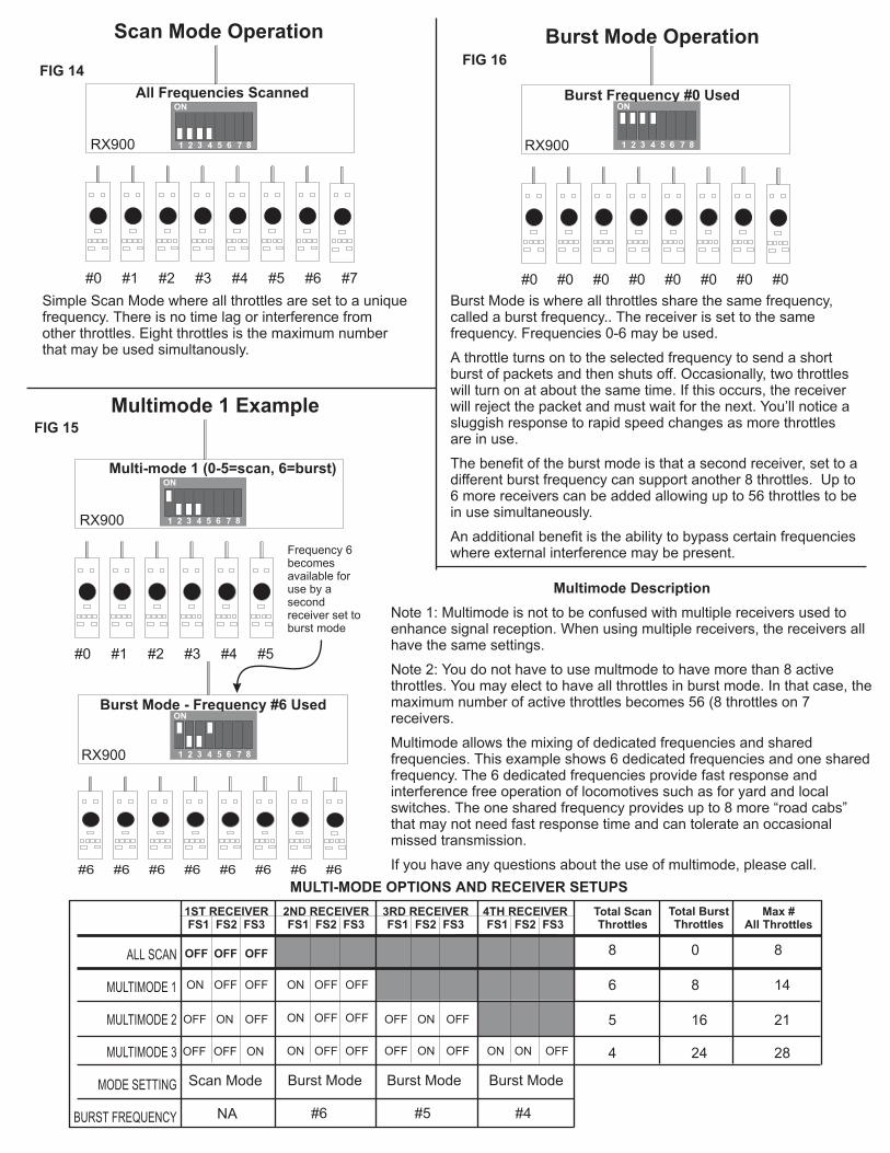
Simple Scan Mode where all throttles are set to a uniquefrequency. There is no time lag or interference fromother throttles. Eight throttles is the maximum numberthat may be used simultanously.
RX900 RX900
Burst Mode is where all throttles share the same frequency,called a burst frequency.. The receiver is set to the samefrequency. Frequencies 0-6 may be used.
A throttle turns on to the selected frequency to send a shortburst of packets and then shuts off. Occasionally, two throttleswill turn on at about the same time. If this occurs, the receiverwill reject the packet and must wait for the next. You’ll notice asluggish response to rapid speed changes as more throttlesare in use.
The benefit of the burst mode is that a second receiver, set to adifferent burst frequency can support another 8 throttles. Up to6 more receivers can be added allowing up to 56 throttles to bein use simultaneously.
An additional benefit is the ability to bypass certain frequencieswhere external interference may be present.
#1#0 #3#2 #5#4
ON
1 2 3 4 5 6 7 8
Multi-mode 1 (0-5=scan, 6=burst)
RX900
#6
Burst Mode - Frequency #6 UsedON
1 2 3 4 5 6 7 8
#6#6 #6 #6 #6 #6 #6
RX900
Frequency 6becomesavailable foruse by asecondreceiver set toburst mode
Multimode Description
Note 1: Multimode is not to be confused with multiple receivers used toenhance signal reception. When using multiple receivers, the receivers allhave the same settings.
Note 2: You do not have to use multmode to have more than 8 activethrottles. You may elect to have all throttles in burst mode. In that case, themaximum number of active throttles becomes 56 (8 throttles on 7receivers.
Multimode allows the mixing of dedicated frequencies and sharedfrequencies. This example shows 6 dedicated frequencies and one sharedfrequency. The 6 dedicated frequencies provide fast response andinterference free operation of locomotives such as for yard and localswitches. The one shared frequency provides up to 8 more “road cabs”that may not need fast response time and can tolerate an occasionalmissed transmission.
If you have any questions about the use of multimode, please call.
Burst Mode OperationScan Mode Operation
Multimode 1 Example
FIG 14
FIG 15
FIG 16
MULTI-MODE OPTIONS AND RECEIVER SETUPS
1ST RECEIVERFS1 FS2 FS3
2ND RECEIVERFS1 FS2 FS3
3RD RECEIVERFS1 FS2 FS3
4TH RECEIVERFS1 FS2 FS3
ALL SCAN
MULTIMODE 1
MULTIMODE 2
MULTIMODE 3
MODE SETTING
BURST FREQUENCY
OFF OFF OFF
OFF OFFON
ON
ON
OFF OFF
OFFOFF
OFF OFFON
Burst Mode Burst Mode Burst ModeScan Mode
ON OFFOFF
ON OFFON
OFF OFFON
OFF OFFON ON OFFOFF
NA #6 #5 #4
Total ScanThrottles
Total BurstThrottles
Max #All Throttles
8 0 8
6 8 14
5 16 21
4 24 28

Fascia Plate
Using A Temporary Patch (Guitar) Cable
You may plug the RX900 receiver into any convenientfascia plate jack using the a Radio Shack two conductorcoiled guitar cord (RS# 42-978). The cord is notincluded in the kit.
This is a handy way to quickly move the RX900receiver about your layout to determine the bestplacement. The RX900 may be placed anywhere alongthe throttle bus
Fascia Plate
Adding F-Jack To Fascia Plate Board
You can connect the RX900 receiver to anyconvenient fascia plate. Included with the RX900receiver are an extra twist-on plug and F-jack.
There is no length limitation although you must followthe cabling guidelines described in your Railcommandusers manual.
Do not use TV cable splitters. They will not work.
Up to 100 feet for RG58 or up to 250feet for RG6 cable is allowed
DIGITAL WIRELESS RX900 RECEIVER
GPCDST 12VACCS2TBUS AC
FS
1
FS
2
FS
3
B/S
E/R
TB
TM
CS
SETUP
Added F-Jack
RG58U Coax
©2000 By CVP Products All Rights Reserved
DIGITAL WIRELESS RX900 RECEIVER
GPCDST 12VACCS2TBUS AC
FS
1
FS
2
FS
3
B/S
E/R
TB
TM
CS
SETUP
RX900 CONNECTION OPTIONS FOR RAILCOMMAND
Basestation Reception Guidelines and Location TipsThere are no hard rules for locating the basestation since each layout environment is different. For this reason, we recommend an extendedperiod of trial and error basestation placement. Use the indicators on the basestation along with the tips below to determine the best location.
1. Pick a spot away from an area that will have a heavy concentration of transmitters.
2. Don’t put the basestation in areas where a transmitter will be permanently stationed. For example, if the basestation is underneath your busyyard, the constant presence of the yard operator’s transmitter can jam weaker signals from distant transmitters.
3. To test a location, temporarily set the basestation in the desired location. Then walk the layout with a SINGLE transmitter. Have someonewatch the base station GP light. If it stays on constantly no matter where the transmitter is located, you’ve found a good spot. Next, perform thesame test with a second transmitter operating while leaving the first unit on. Continue doing this until all active transmitters achieve goodreception.
However, if the light flickers or goes out, relocate the basestation and try again. In many cases a move of less than 1 foot can make a dramaticdifference in reception. Also, placement should be tried in all different directions, including vertical.
4. If you find a chronic weak area, physically move the basestation towards the weaker area.
5. For best signal transmission, hold the throttle so the antenna is vertical. Don’t place your hand around the antenna.
6. Keep the basestation away from Fluorescent lights.
7. Homemade and store-bought dimmers for layout lighting may cancel out the transmitter’s signal. If you have a lighting sytem like this,consider not using it or equipping it with UL approved line filters.
8. Make sure there are no metallic objects near the basestation antenna. Keep all other materials away from the antenna.
9. Consider using a line filter if the basestation is plugged into the same power outlet as the CTC80 system. Line filters can be purchased fromRadio Shack or other electrical supply houses. This is different than a “surge limiter” so unless it says “line filter,” don’t waste your money.
10. Train your operators to recognize when the basestation has dropped their throttle. If this occurs, it is the same as if a regular tetheredthrottle was unplugged. In most cases, control can be regained by simply moving. In some cases, this may be nothing more than moving lessthan 12 inches. Let us know if you encounter something unique or different and how you managed radio reception on your layout.