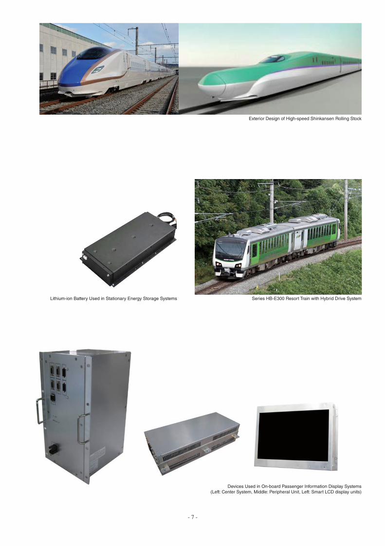
railway systems · exterior design of high-speed shinkansen rolling stock devices used in on-board...
TRANSCRIPT
www.hitachi.com/rev
Volume 63 Number 10 March 2015
Railway systems
The social trends relevant to railway systems are undergoing rapid
changes along with changes in society and advances in
technology.
Given this changing environment, what can Hitachi do to aid the
ongoing development of the railway industry? I believe it is
important for us to always keep this question in mind.
As a total system integrator for the railway industry, involved in
traffic and power management systems and information services
as well as rolling stock and traction drive control equipment, Hitachi
is developing advanced technology to contribute to ongoing
progress toward faster trains, higher traffic densities, more
punctual services, and reliable operation. While railways are
closely tied to the regions they serve, there is growing demand for
the technologies they use to be designed for global use.
Accordingly, Hitachi is developing technologies that comply with
the requirements of different countries and regions such as the UK
and China as well as Japan.
In terms of technical developments in individual fields, namely
rolling stock, Hitachi is working to achieve lighter weight, and on
developments that include battery-based techniques for saving
energy and next-generation traction drive systems. To improve
passenger comfort and provide barrier-free accessibility,
meanwhile, Hitachi supplies passenger information services that
use on-board displays and is equipping its products with
barrier-free fittings.
For wayside systems, Hitachi is developing more advanced
traffic management systems and technology for providing trains
with emergency power using a stationary energy storage system. It
is also taking steps to improve the productivity of maintenance and
inspection work.
In an initiative aimed at improving energy efficiency, an energy
management system is being developed to coordinate on-board
systems with wayside systems for traffic management, substations,
and power management. This issue of Hitachi Review focuses on
describing this work.
Hitachi is seeking to combine its comprehensive railway industry
capabilities built up over time with technologies from across the
Hitachi Group to contribute to innovation in the next generation of
railway systems that place less of a load on the environment.
I hope this issue of Hitachi Review will help you gain a better
understanding of the activities of Hitachi’ s Social Innovation
Business.
Fujihiko YokoseSenior Engineer
R&D Planning Office,
Corporate Development & Strategy Division
Rail Systems Company
Hitachi, Ltd.
From the Editor
Editorial Coordinator
Volume 63 Number 10 March 2015
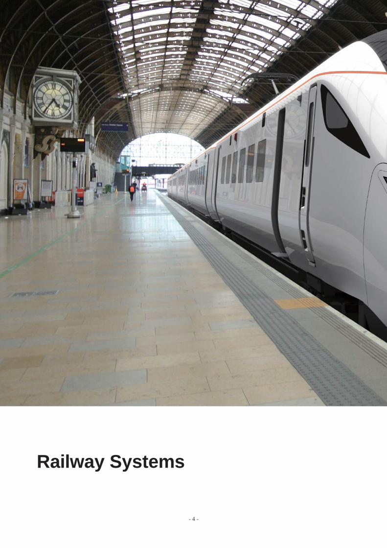
Railway Systems
- 4 -
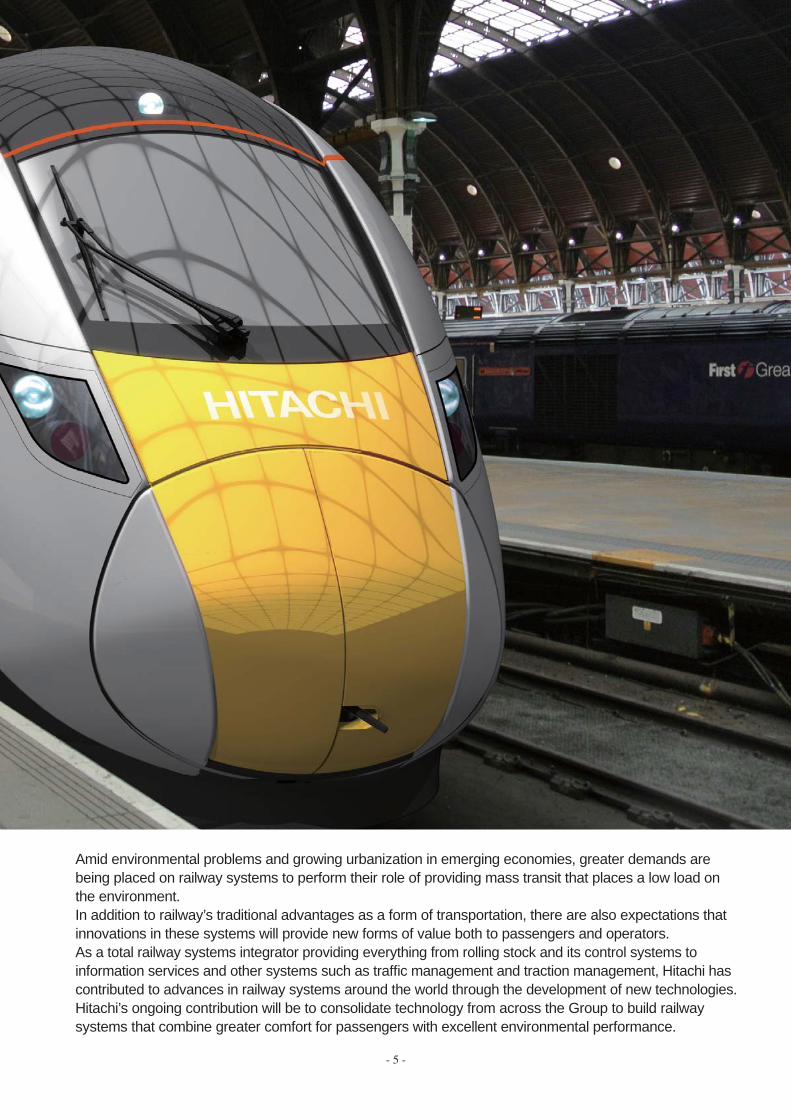
Amid environmental problems and growing urbanization in emerging economies, greater demands are being placed on railway systems to perform their role of providing mass transit that places a low load on the environment.In addition to railway’s traditional advantages as a form of transportation, there are also expectations that innovations in these systems will provide new forms of value both to passengers and operators.As a total railway systems integrator providing everything from rolling stock and its control systems to information services and other systems such as traffi c management and traction management, Hitachi has contributed to advances in railway systems around the world through the development of new technologies.Hitachi’s ongoing contribution will be to consolidate technology from across the Group to build railway systems that combine greater comfort for passengers with excellent environmental performance.
- 5 -

- 6 -
Class800/801 High-speed Rolling Stock for the UK IEP Project (Left: Artist’s Impression, Top-right: Driving Cab, Bottom-right: First Class Compartment)
Consolidated Integrated Control Center for
Traffic Management System Controlling Four Lines
New 10000 Series Rolling Stock for Tokyo Monorail (Left: Monorail Vehicle, Right: Driving Cab)
Example Screen of New Portable Radio Terminal
- 7 -
Exterior Design of High-speed Shinkansen Rolling Stock
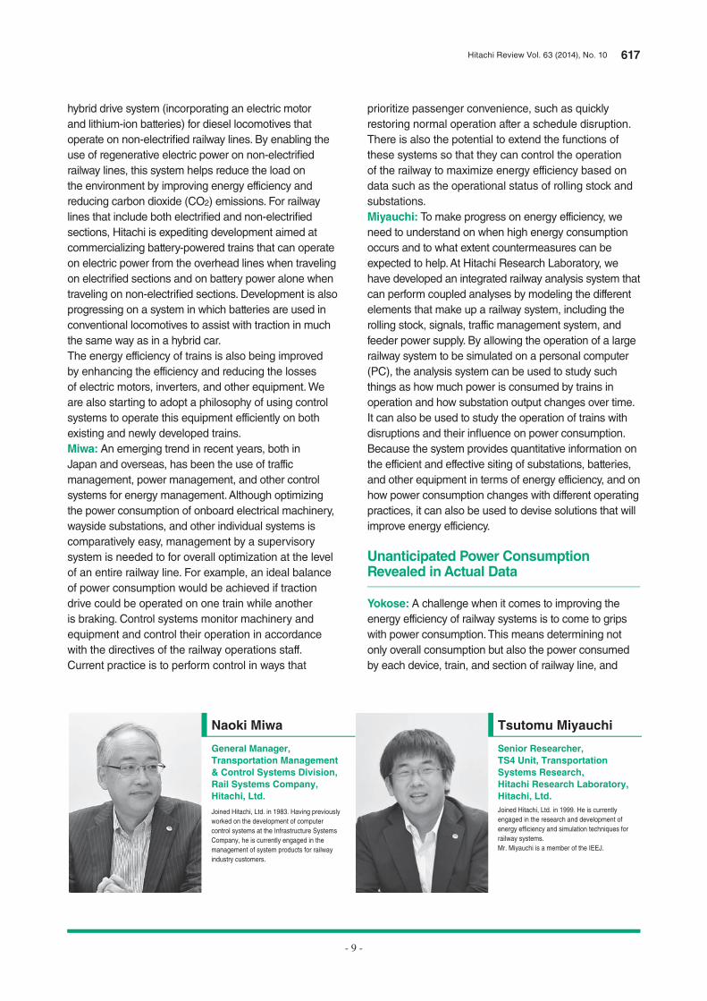
Devices Used in On-board Passenger Information Display Systems
(Left: Center System, Middle: Peripheral Unit, Left: Smart LCD display units)
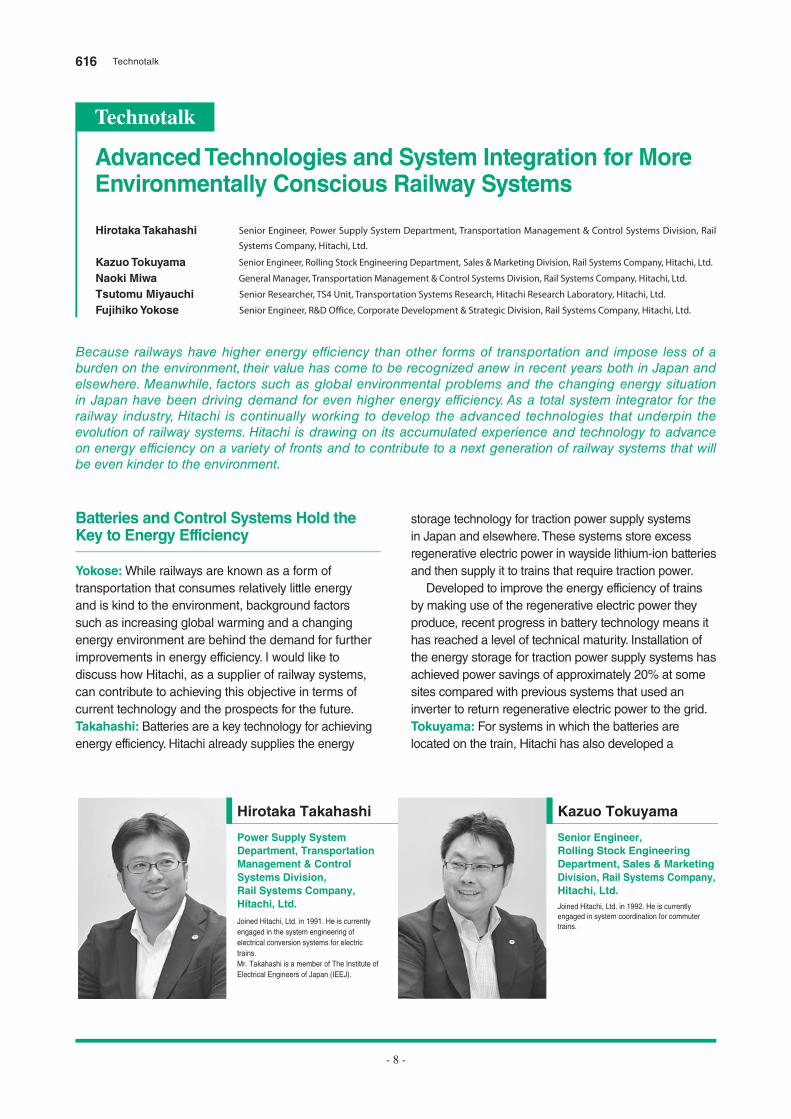
Lithium-ion Battery Used in Stationary Energy Storage Systems Series HB-E300 Resort Train with Hybrid Drive System
- 8 -
Because railways have higher energy efficiency than other forms of transportation and impose less of a burden on the environment, their value has come to be recognized anew in recent years both in Japan and elsewhere. Meanwhile, factors such as global environmental problems and the changing energy situation in Japan have been driving demand for even higher energy efficiency. As a total system integrator for the railway industry, Hitachi is continually working to develop the advanced technologies that underpin the evolution of railway systems. Hitachi is drawing on its accumulated experience and technology to advance on energy efficiency on a variety of fronts and to contribute to a next generation of railway systems that will be even kinder to the environment.
Batteries and Control Systems Hold the Key to Energy Efficiency
Yokose: While railways are known as a form of
transportation that consumes relatively little energy
and is kind to the environment, background factors
such as increasing global warming and a changing
energy environment are behind the demand for further
improvements in energy efficiency. I would like to
discuss how Hitachi, as a supplier of railway systems,
can contribute to achieving this objective in terms of
current technology and the prospects for the future.
Takahashi: Batteries are a key technology for achieving
energy efficiency. Hitachi already supplies the energy
storage technology for traction power supply systems
in Japan and elsewhere. These systems store excess
regenerative electric power in wayside lithium-ion batteries
and then supply it to trains that require traction power.
Developed to improve the energy efficiency of trains
by making use of the regenerative electric power they
produce, recent progress in battery technology means it
has reached a level of technical maturity. Installation of
the energy storage for traction power supply systems has
achieved power savings of approximately 20% at some
sites compared with previous systems that used an
inverter to return regenerative electric power to the grid.
Tokuyama: For systems in which the batteries are
located on the train, Hitachi has also developed a
Hirotaka Takahashi Senior Engineer, Power Supply System Department, Transportation Management & Control Systems Division, Rail
Systems Company, Hitachi, Ltd.
Kazuo Tokuyama Senior Engineer, Rolling Stock Engineering Department, Sales & Marketing Division, Rail Systems Company, Hitachi, Ltd.
Naoki Miwa General Manager, Transportation Management & Control Systems Division, Rail Systems Company, Hitachi, Ltd.
Tsutomu Miyauchi Senior Researcher, TS4 Unit, Transportation Systems Research, Hitachi Research Laboratory, Hitachi, Ltd.
Fujihiko Yokose Senior Engineer, R&D Office, Corporate Development & Strategic Division, Rail Systems Company, Hitachi, Ltd.
Advanced Technologies and System Integration for More Environmentally Conscious Railway Systems
Technotalk
Power Supply System Department, Transportation Management & Control Systems Division, Rail Systems Company, Hitachi, Ltd.
Hirotaka Takahashi
Joined Hitachi, Ltd. in 1991. He is currently
engaged in the system engineering of
electrical conversion systems for electric
trains.
Mr. Takahashi is a member of The Institute of
Electrical Engineers of Japan (IEEJ).
Senior Engineer, Rolling Stock Engineering Department, Sales & Marketing Division, Rail Systems Company, Hitachi, Ltd.
Kazuo Tokuyama
Joined Hitachi, Ltd. in 1992. He is currently
engaged in system coordination for commuter
trains.
616 Technotalk
Hitachi Review Vol. 63 (2014), No. 10 617
prioritize passenger convenience, such as quickly
restoring normal operation after a schedule disruption.
There is also the potential to extend the functions of
these systems so that they can control the operation
of the railway to maximize energy efficiency based on
data such as the operational status of rolling stock and
substations.
Miyauchi: To make progress on energy efficiency, we
need to understand on when high energy consumption
occurs and to what extent countermeasures can be
expected to help. At Hitachi Research Laboratory, we
have developed an integrated railway analysis system that
can perform coupled analyses by modeling the different
elements that make up a railway system, including the
rolling stock, signals, traffic management system, and
feeder power supply. By allowing the operation of a large
railway system to be simulated on a personal computer
(PC), the analysis system can be used to study such
things as how much power is consumed by trains in
operation and how substation output changes over time.
It can also be used to study the operation of trains with
disruptions and their infl uence on power consumption.
Because the system provides quantitative information on
the efficient and effective siting of substations, batteries,
and other equipment in terms of energy efficiency, and on
how power consumption changes with different operating
practices, it can also be used to devise solutions that will
improve energy efficiency.
Unanticipated Power Consumption Revealed in Actual Data
Yokose: A challenge when it comes to improving the
energy efficiency of railway systems is to come to grips
with power consumption. This means determining not
only overall consumption but also the power consumed
by each device, train, and section of railway line, and
hybrid drive system (incorporating an electric motor
and lithium-ion batteries) for diesel locomotives that
operate on non-electrifi ed railway lines. By enabling the
use of regenerative electric power on non-electrifi ed
railway lines, this system helps reduce the load on
the environment by improving energy efficiency and
reducing carbon dioxide (CO2) emissions. For railway
lines that include both electrifi ed and non-electrifi ed
sections, Hitachi is expediting development aimed at
commercializing battery-powered trains that can operate
on electric power from the overhead lines when traveling
on electrifi ed sections and on battery power alone when
traveling on non-electrifi ed sections. Development is also
progressing on a system in which batteries are used in
conventional locomotives to assist with traction in much
the same way as in a hybrid car.
The energy efficiency of trains is also being improved
by enhancing the efficiency and reducing the losses
of electric motors, inverters, and other equipment. We
are also starting to adopt a philosophy of using control
systems to operate this equipment efficiently on both
existing and newly developed trains.
Miwa: An emerging trend in recent years, both in
Japan and overseas, has been the use of traffic
management, power management, and other control
systems for energy management. Although optimizing
the power consumption of onboard electrical machinery,
wayside substations, and other individual systems is
comparatively easy, management by a supervisory
system is needed to for overall optimization at the level
of an entire railway line. For example, an ideal balance
of power consumption would be achieved if traction
drive could be operated on one train while another
is braking. Control systems monitor machinery and
equipment and control their operation in accordance
with the directives of the railway operations staff.
Current practice is to perform control in ways that
- 9 -
General Manager, Transportation Management & Control Systems Division, Rail Systems Company, Hitachi, Ltd.
Naoki Miwa
Joined Hitachi, Ltd. in 1983. Having previously
worked on the development of computer
control systems at the Infrastructure Systems
Company, he is currently engaged in the
management of system products for railway
industry customers.
Senior Researcher, TS4 Unit, Transportation Systems Research,Hitachi Research Laboratory, Hitachi, Ltd.
Tsutomu Miyauchi
Joined Hitachi, Ltd. in 1999. He is currently
engaged in the research and development of
energy efficiency and simulation techniques for
railway systems.
Mr. Miyauchi is a member of the IEEJ.

by traction), then the proportion of regenerative electric
power consumed by SIVs is only about 25%. If SIV power
consumption increases further, however, less excess
regenerative electric power will be available because a
growing proportion will be used by the SIVs, and this can
be expected to affect the level of power savings achieved.
Takahashi: That’s right. This tendency is particularly
evident when there is a long distance of railway line
between substations.
Use of Control Systems to Support Energy-efficient Operation
Miyauchi: Overall train power consumption depends on
operating conditions, with running resistance and the drive
system believed to have particularly signifi cant infl uences.
Because running resistance is a function of the speed at
which a train is traveling, operating practices that minimize
variations in speed will help save energy. In particular,
when schedule disruptions occur, control techniques
that can minimize acceleration and deceleration and
allow trains to run at a slow speed as needed will reduce
power consumption. Given that achieving this requires
techniques for obtaining accurate location and movement
data about trains on the railway line, it should be possible
to use traffic management system technology for this
purpose.
Tokuyama: As you say, accelerating from a halt uses a
large amount of energy and therefore allowing trains to
proceed at a slow speed will reduce power consumption.
Because trains are able to obtain information such as
passenger load factors and how long to stop at stations,
it should be possible to achieve even greater energy
savings by using this information in the supervisory traffic
management system to coordinate operations in realtime,
including departure times and modifying the speed of
following trains.
- 10 -
also the factors that cause their power consumptions to
change. While simulation naturally plays an important
role, being able to visualize the details of actual
consumption is also essential for assessing the benefi ts
of investment.
Takahashi: While the only way to do this at present is
to infer power consumption from data or other status
information, we have also made one very interesting
inference. When we looked at the year-long results of
measuring the benefi ts of energy storage for a traction
power supply system in collaboration with the railway
operator, we found that trains running above ground have
excess regenerative electric power during spring and
fall, but that the amount of excess returned to the energy
storage for traction power supply system falls in mid-
summer and mid-winter. In contrast, measurements from
systems installed on underground trains showed little
evidence of this seasonal variation. We believe the reason
why regenerative electric power generated when the
temperature is high or low is consumed within the train is
because most of it is being used by auxiliary systems such
as air conditioning. We hadn’t anticipated that the amount
of power consumed by these auxiliary systems would be
so high. Given that the weather has a major infl uence on
the power consumption of trains that run above ground,
signifi cant energy savings should be possible by performing
detailed control of the auxiliary power supplies used on
trains for air conditioning and other purposes.
Miyauchi: Something we have discovered only recently
is that the power consumed by the static inverters
(SIVs) used to supply air conditioning and other
auxiliary equipment has a much bigger impact on the
energy savings achieved by energy storage systems
than was previously thought. Assuming that the power
used by SIVs is about 10% of the traction drive power
consumption, and that the regeneration rate is 40%
(regeneration produces 40% of the power consumed
Senior Engineer, R&D Office, Corporate Development & Strategic Division, Rail Systems Company, Hitachi, Ltd.
Fujihiko Yokose
Joined Hitachi, Ltd. in 1988. Having previously
been involved in engineering work for railway
systems, he is currently engaged in the
management of railway technology
development.
618 Technotalk
Hitachi Review Vol. 63 (2014), No. 10 619
that impose less of a load on the environment and
therefore our aim is to contribute by developing models
that successfully combine batteries with equipment and
control systems.
Miyauchi: Hitachi is engaged in the broad-based
development and supply of railway system technologies
that extend from rolling stock, signaling systems, traffic
management systems, and substations to hybrid
drive systems that combine engines, electric motors,
and batteries, and has a variety of energy efficiency
technologies that are based on the experience and
knowledge built up through this work. While the benefi ts
of new energy-saving systems that utilize these
technologies can be estimated by using collected data
and the simulations described earlier, we still want to
verify them on actual railways.
Miwa: Most past developments have been undertaken
to fulfi ll customer requirements, but to deliver the sort of
value represented by energy efficiency, I believe we fi rst
need to build our own models that will indicate a certain
level of benefi ts and then to prove them in demonstration
projects. To achieve this, we should further enhance
our technology in-house and expedite measures
aimed at moving to the next stage, such as enhancing
interoperation between systems.
Yokose: It is now possible in the railway industry to
collect large amounts of diverse forms of data from
numerous subsystems. Key factors to success will be
our ability to apply the know-how we have accumulated
through our railway business to the analysis of this big
data, and whether we will be able to utilize it to improve
energy efficiency.
We are approaching a period of transition to more
sophisticated systems in which the railway systems that
in the past have been developed to ensure safe and
punctual operation will need also to take account of
energy efficiency. Along with railway technology, other
technologies with an important role in this transition
will include wireless communications and the global
positioning system (GPS) for obtaining accurate train
locations, and data transmission techniques for the
precise control of substations.
The Social Innovation Business that Hitachi is pursuing
on a group-wide basis seeks to create new value through
infrastructure innovation in collaboration with customers.
Likewise with railway systems, our aim is to combine the
comprehensive capabilities we have built up in the railway
industry with technology and knowledge from elsewhere
in the group to contribute to innovations that will help
develop the next generation of railway systems so that
they impose less of a load on the environment.
Miwa: As traffic management systems are designed with
an emphasis on how quickly trains can get from station
to station and how close together trains can run, there is
no system-level defi nition of how to operate for energy
efficiency. While this is a natural consequence of giving
precedence to ensuring the transportation capabilities
of the railway in its role as public infrastructure, I believe
we also need to be concerned with electric power in the
future. Furthermore, an important aspect of doing this will
be how a system-based approach to minimizing power
consumption can be made to support operations in a way
that is compatible with the instincts of the train drivers.
On the other hand, combining this with automatic train
operation (ATO) and implementing operating schedules
that are designed for optimal energy efficiency offers an
alternative approach, and I believe we need to continue
collecting data and identifying the technical possibilities.
Yokose: In terms of supporting energy-efficient operation,
it is also important to consider what capabilities control
systems can offer.
Miwa: Since the driver cannot see the train ahead, unlike
in a car, a key point will be how the supervisory traffic
management system can make this information available
and use it to support operations or to automate the
operational coordination of multiple trains.
Integrating Technologies for Innovation in Railway Systems
Takahashi: The pursuit of energy efficiency also requires
measures for dealing with losses on feeder power lines.
I believe that using substations to control the voltage
supplied to feeder lines is one effective technique for
achieving this.
However, because few substations are currently able
to control the feeder line voltage, it is anticipated that
the ideal method will be to perform realtime control of
feeder line voltage in conjunction with the use of wireless
technology and batteries. This will likely involve the
deployment of train control system technology that uses
radio communications, like that in the communications-
based train control system (CBTC).
Tokuyama: Batteries installed on the wayside can
also be used in that way. Along with using them for
energy efficiency, we are also trialing their use as an
emergency power supply so that trains can reach the
next station when a major power outage occurs. The
fact that Hitachi’s business encompasses both batteries
and railway systems can be seen as a major technical
strength. While battery technology still requires further
technical innovations in areas such as weight and cost,
the technology will be essential for future railway systems
- 11 -
620 Hitachi Review Vol. 63 (2014), No. 10
- 12 -
Overview
Railway Systems Designed for Greater Comfort and
Environmental Performance
Fujihiko Yokose
Yoshimitsu Nakazawa
Shigenori Iwamura
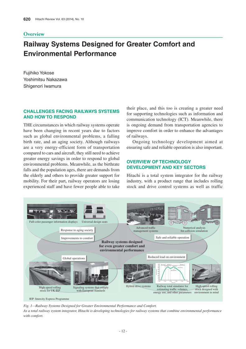
CHALLENGES FACING RAILWAYS SYSTEMS
AND HOW TO RESPOND
THE circumstances in which railway systems operate have been changing in recent years due to factors such as global environmental problems, a falling birth rate, and an aging society. Although railways are a very energy-efficient form of transportation compared to cars and aircraft, they still need to achieve greater energy savings in order to respond to global environmental problems. Meanwhile, as the birthrate falls and the population ages, there are demands from the elderly and others to provide greater support for mobility. For their part, railway operators are losing experienced staff and have fewer people able to take
their place, and this too is creating a greater need for supporting technologies such as information and communication technology (ICT). Meanwhile, there is ongoing demand from transportation agencies to improve comfort in order to enhance the advantages of railways.
Ongoing technology development aimed at ensuring safe and reliable operation is also important.
OVERVIEW OF TECHNOLOGY
DEVELOPMENT AND KEY SECTORS
Hitachi is a total system integrator for the railway industry, with a product range that includes rolling stock and drive control systems as well as traffic
Response to aging society
Full-color passenger information displays
High-speed rollingstock for UK IEP
Signaling systems that complywith European standards
Hybrid drive systems High-speed rollingstock designed withenvironment in mind
Railway total simulator forestimating traffic volumes,
energy use, and other parameters
Universal design seats
Advanced trafficmanagement systems
Numerical analysisfor collision simulation
Improvements to comfort
Global operations Reduced load on environment
Safe and reliable operation
Railway systems designedfor even greater comfort andenvironmental performance
3,7000
10
20
30
40
50
60
70
3,720 3,740 3,760Time [s]
Spee
d [k
m/h
]
PoweringCoasting 1 Coasting 2
Braking 1 Braking 2
Simulation
Measurement
3,780 3,800
Fig. 1—Railway Systems Designed for Greater Environmental Performance and Comfort.As a total railway system integrator, Hitachi is developing technologies for railway systems that combine environmental performance with comfort.
IEP: Intercity Express Programme
Hitachi Review Vol. 63 (2014), No. 10 621
- 13 -
management systems(a), power management systems, and information services. It develops advanced technologies for faster trains, higher traffic densities, more punctual service, and more reliable operation, so that it can contribute to advances in these fields. As a global company, Hitachi supplies products throughout the world. This makes it able to contribute to the development of railways not only in Japan but also in other countries such as the UK and China, with products including medium- and high-speed rolling stock and signaling systems that comply with European standards (see Fig. 1).
Table 1 lists the challenges that railways need to overcome and the main research and development being undertaken to achieve this.
The first challenge is energy efficiency, a field in which developments by Hitachi include reducing the weight of rolling stock to reduce energy use and energy-saving technologies based on the use of batteries. The second challenge is to improve comfort. Work in this area includes providing passengers with information services using on-board displays, and making its products barrier-free (accessible to the disabled). The third challenge is to improve operational safety and reliability. Examples of this work include further development of traffic management systems, the development of
techniques for providing emergency traction power using regenerative energy storage systems, and improvements to the productivity of maintenance and inspection work. Through these technical developments, Hitachi aims to contribute to the ongoing future progress of railway systems.
DEVELOPMENT OF TECHNOLOGY FOR
ROLLING STOCK SYSTEMS
Hitachi supplies rolling stock for Shinkansen and commuter trains, designed to reduce the load on the environment by being built from aluminum alloy for light weight. To meet demands over recent years for improved comfort, Hitachi has adopted active suspension(b) on its latest high-speed Shinkansen rolling stock to minimize the transmission of vibrations through the floor when traveling at high speed.
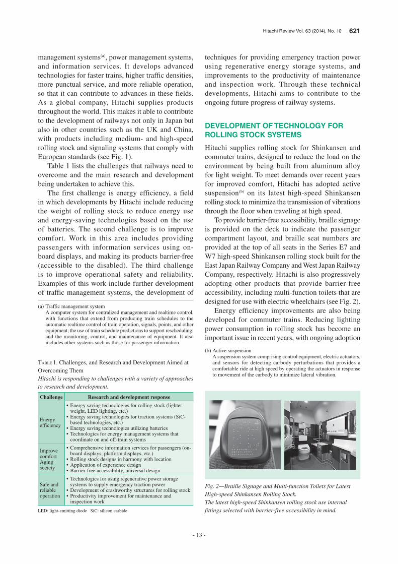
To provide barrier-free accessibility, braille signage is provided on the deck to indicate the passenger compartment layout, and braille seat numbers are provided at the top of all seats in the Series E7 and W7 high-speed Shinkansen rolling stock built for the East Japan Railway Company and West Japan Railway Company, respectively. Hitachi is also progressively adopting other products that provide barrier-free accessibility, including multi-function toilets that are designed for use with electric wheelchairs (see Fig. 2).
Energy efficiency improvements are also being developed for commuter trains. Reducing lighting power consumption in rolling stock has become an important issue in recent years, with ongoing adoption
Challenge Research and development response
Energy efficiency
• Energy saving technologies for rolling stock (lighter weight, LED lighting, etc.)
• Energy saving technologies for traction systems (SiC-based technologies, etc.)
• Energy saving technologies utilizing batteries• Technologies for energy management systems that
coordinate on and off-train systems
Improve comfortAging society
• Comprehensive information services for passengers (on-board displays, platform displays, etc.)
• Rolling stock designs in harmony with location• Application of experience design• Barrier-free accessibility, universal design
Safe and reliable operation
• Technologies for using regenerative power storage systems to supply emergency traction power
• Development of crashworthy structures for rolling stock• Productivity improvement for maintenance and
inspection work
TABLE 1. Challenges, and Research and Development Aimed at Overcoming ThemHitachi is responding to challenges with a variety of approaches to research and development.
LED: light-emitting diode SiC: silicon carbide
(a) Traffic management system A computer system for centralized management and realtime control,
with functions that extend from producing train schedules to the automatic realtime control of train operation, signals, points, and other equipment; the use of train schedule predictions to support rescheduling; and the monitoring, control, and maintenance of equipment. It also includes other systems such as those for passenger information.
(b) Active suspension A suspension system comprising control equipment, electric actuators,
and sensors for detecting carbody perturbations that provides a comfortable ride at high speed by operating the actuators in response to movement of the carbody to minimize lateral vibration.
Fig. 2—Braille Signage and Multi-function Toilets for Latest High-speed Shinkansen Rolling Stock.The latest high-speed Shinkansen rolling stock use internal fittings selected with barrier-free accessibility in mind.

622 Railway Systems Designed for Greater Comfort and Environmental Performance
- 14 -
of light-emitting diodes (LEDs) for headlights. Hitachi has demonstrated that LED headlights can provide better visibility and illumination than the sealed beam or high-intensity discharge (HID) lamps used in the past. The power consumption of LED headlights is only about one-sixth that of HID headlights.
Universal design (UD) seats are increasingly being adopted at public and medical institutions to provide priority seating that is less physically demanding to use for those such as the elderly or people with reduced mobility who need a long time to sit down or stand up. Hitachi is working on development aimed at adapting these UD seats for use on trains. Based on market research and other studies, Hitachi has identified “having the seat higher off the ground but shorter in the depth direction to make sitting down and standing up easier” as a key requirement, and is aiming to develop seats that provide the following benefits: (1) reduced physical effort for sitting down by avoiding the need for major bending of the knee, and (2) a larger available area in the train interior by raising seat height and making seats less deep. To prepare for commercial use, Hitachi evaluated and tested these UD seats under actual conditions (see Fig. 3).
Hitachi has also developed the 10000 Series monorail rolling stock for Tokyo Monorail. This series is based on Hitachi’s A-train technology and optimized for use on monorails. The carbodies are built from lightweight and easily recyclable aluminum alloy, and use friction stir welding (FSW), a proven technology for carbody welding, to minimize welding-induced distortion. The exterior design represents the sky, sea, and parkland character of the surrounding area (see Fig. 4).
DEVELOPMENT OF NEXT GENERATION OF
TRACTION DRIVE SYSTEMS
Along with reducing the losses from individual items of equipment such as the inverter and traction motors, Hitachi is also seeking to improve the energy efficiency of traction drive systems by working on developments that use system control to reduce power consumption. Fig. 5 lists work being undertaken on the next generation of traction drive systems.
For inverters, Hitachi has been improving the efficiency of individual components by, for example, developing silicon carbide (SiC) hybrid modules. These modules succeed in reducing inverter size and weight by 40% and power loss by 35%, compared with the silicon (Si) components typically used in past inverters.
To improve energy efficiency further, Hitachi has developed a technique that uses PWM(c) control to reduce motor losses.
Fig. 3—Mockup of UD Seat.Hitachi is developing UD seats for use in trains.
Fig. 4—TMK10000 Series Monorail.The exterior design was chosen to harmonize with the surrounding area.
Energy efficiency→ Reduce power
consumption.
SiC inverter
Equipmentoptimization System optimization
Low-loss traction motors
Control techniques that reducelosses in traction motors
Operation support technology
Control techniquesthat use batteries
Battery technologies
Longer component life
Online monitoring
Reduce workload→ Reduce maintenance
staffing.
Safe and reliable operation→ Give passengers
peace of mind.
Fig. 5—Work on Next Generation of Traction Drive Systems.Development work extends from the optimization of individual items of equipment up to system optimization.
(c) PWM Abbreviation of “pulse width modulation.” A technique for controlling
output voltage (and current) by varying the on-time (width) of pulses (electric signals that alternate between on and off). The technique has excellent controllability and efficiency, and is widely used in inverters.
Hitachi Review Vol. 63 (2014), No. 10 623
- 15 -
Hitachi is also improving the efficiency of traction motors by developing techniques that reduce the losses that occur in these motors, including iron losses, copper losses, mechanical losses, and harmonic losses(d). To reduce iron and copper losses, Hitachi is increasingly utilizing the low-loss materials used in traction motors for the Shinkansen in commuter trains also. Hitachi has succeeded in reducing total losses by approximately 11% compared with previous models by using detailed analysis of magnetic fields to determine the harmonic flux distribution in traction motors and then developing inverter control to reduce harmonic losses, and also by developing traction motors that use low-loss materials.
GLOBAL OPERATIONS
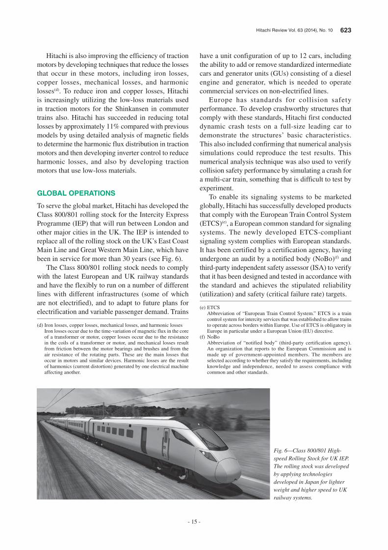
To serve the global market, Hitachi has developed the Class 800/801 rolling stock for the Intercity Express Programme (IEP) that will run between London and other major cities in the UK. The IEP is intended to replace all of the rolling stock on the UK’s East Coast Main Line and Great Western Main Line, which have been in service for more than 30 years (see Fig. 6).
The Class 800/801 rolling stock needs to comply with the latest European and UK railway standards and have the flexibly to run on a number of different lines with different infrastructures (some of which are not electrified), and to adapt to future plans for electrification and variable passenger demand. Trains
have a unit configuration of up to 12 cars, including the ability to add or remove standardized intermediate cars and generator units (GUs) consisting of a diesel engine and generator, which is needed to operate commercial services on non-electrified lines.
Europe has standards for collision safety performance. To develop crashworthy structures that comply with these standards, Hitachi first conducted dynamic crash tests on a full-size leading car to demonstrate the structures’ basic characteristics. This also included confirming that numerical analysis simulations could reproduce the test results. This numerical analysis technique was also used to verify collision safety performance by simulating a crash for a multi-car train, something that is difficult to test by experiment.
To enable its signaling systems to be marketed globally, Hitachi has successfully developed products that comply with the European Train Control System (ETCS)(e), a European common standard for signaling systems. The newly developed ETCS-compliant signaling system complies with European standards. It has been certified by a certification agency, having undergone an audit by a notified body (NoBo)(f) and third-party independent safety assessor (ISA) to verify that it has been designed and tested in accordance with the standard and achieves the stipulated reliability (utilization) and safety (critical failure rate) targets.
(d) Iron losses, copper losses, mechanical losses, and harmonic losses Iron losses occur due to the time-variation of magnetic flux in the core
of a transformer or motor, copper losses occur due to the resistance in the coils of a transformer or motor, and mechanical losses result from friction between the motor bearings and brushes and from the air resistance of the rotating parts. These are the main losses that occur in motors and similar devices. Harmonic losses are the result of harmonics (current distortion) generated by one electrical machine affecting another.
(e) ETCS Abbreviation of “European Train Control System.” ETCS is a train
control system for intercity services that was established to allow trains to operate across borders within Europe. Use of ETCS is obligatory in Europe in particular under a European Union (EU) directive.
(f) NoBo Abbreviation of “notified body” (third-party certification agency).
An organization that reports to the European Commission and is made up of government-appointed members. The members are selected according to whether they satisfy the requirements, including knowledge and independence, needed to assess compliance with common and other standards.
Fig. 6—Class 800/801 High-speed Rolling Stock for UK IEP.The rolling stock was developed by applying technologies developed in Japan for lighter weight and higher speed to UK railway systems.

624 Railway Systems Designed for Greater Comfort and Environmental Performance
- 16 -
them in real terms. Specifically, one of the main approaches adopted is based on a human-centered design process and aims to work through an iterative process that involves (1) understanding the users, (2) identifying what they want, (3) building a prototype, and (4) evaluating how well the users are satisfied.
In developing the new portable terminal, Hitachi accompanied engineering workers engaged in overnight maintenance work to observe their use of these devices and to hold consultations. Next, Hitachi determined the design concepts and produced rough sketches and real-size mock-ups to consider the graphic design. Through a process of repeatedly obtaining feedback (comments and suggestions) regarding things like changes to coloration and button layout, they succeeded in developing a new device that is easy for users to operate.
Coinciding with the establishment of a new integrated control center by the Bureau of Transportation, Tokyo Metropolitan Government, the agency responsible for Tokyo’s subways, the traffic management systems for the Toei subway lines (Mita Line, Asakusa Line, Shinjuku Line, and Oedo Line) were progressively upgraded beginning in February 2013, with the last line being completed in February 2014.
The upgrade shifted all of the central systems to an integrated control center. Traffic management work has also been made more efficient by having a common user interface, including the traffic display panels for each line that are installed side-by-side in the control room, and also the supervisory control desk screens and inputs (see Fig. 7).
In a measure aimed at ensuring safe and reliable operation, the project included the installation of new
The ETCS-compliant signaling system is the first such safety equipment developed by a non-European supplier to be certified as complying with European standards and with safety integrity level 4 (SIL4)(g). Hitachi is actively marketing the system in the UK and other markets around the world.
ADVANCES IN TRAFFIC MANAGEMENT
SYSTEMS AND SERVICES FOR
PRESENTING PASSENGERS WITH EASY-
TO-UNDERSTAND INFORMATION
The Autonomous Decentralized Transport Operation Control System (ATOS) is the main control system for railway services in the Tokyo region and is operated by the East Japan Railway Company. In addition to traffic management, it also supports better services for passengers and helps improve the safety of the engineering workers responsible for the maintenance and inspection of railway infrastructure. Having been in service for 18 years, ATOS is currently undergoing a major system-wide upgrade. This includes a major update to the portable terminals used by engineering workers (the “portable terminal for engineering works”) based on an experience design approach.
Experience design is about imbuing products and services with the potential for users to obtain rich experiences. This is achieved by identifying users’ explicit and implicit requirements and then presenting
(g) SIL4 An abbreviation of “safety integrity level,” SIL is a measure of safety
level specified in the IEC 61508 international standard for functional safety based on the magnitude of risks posed by plants and other systems. The four safety levels are from SIL1 to SIL4, with SIL4 representing the highest level.
Fig. 7—Control Room at Integrated Control Center.Traffic monitoring and automatic control of all trains on four lines is handled from supervisory control desks and the traffic display panels for each line that are installed side-by-side in the control room.

Hitachi Review Vol. 63 (2014), No. 10 625
- 17 -
seven sites. To save power, the regenerative electric power produced during braking is supplied via the overhead lines to other trains that require traction power. However, this regenerative braking becomes unavailable when the number of trains able to use the power falls, such as at off-peak times. The SESS solves this problem by installing wayside batteries to store this regenerative electric power.
Since the Great East Japan Earthquake, there have been heightened concerns about power outages caused by major disasters and other emergencies, and about how to deal with tsunamis. This has led to growing demand from railway operators throughout Japan for the ability to use stored electric power to provide emergency traction power during such an outage. Hitachi and Tokyo Metro Co., Ltd. undertook a demonstration project for such an emergency power system using the technology developed for SESS. This included planning, designing equipment, installing
notification displays and the establishment of a new method for delivering operational instructions to train and station staff, integrating these with the automatic rescheduling function to ensure the timely provision of operational instructions to train and station staff and to prevent delays from being exacerbated.
Additionally, the passenger information displays on the Asakusa Line were upgraded to full-color LED displays. These displays provide passengers with easy-to-understand information on train services by using a color-coded display for the various services along the Asakusa Line, including a through-train linking Haneda Airport (Tokyo International Airport) and Narita International Airport.
EASY-TO-UNDERSTAND ON-BOARD
PASSENGER INFORMATION DISPLAYS
On-board passenger information displays have increasingly been installed on commuter trains in recent years to provide better passenger information. Hitachi commenced serious development in 2006, by performing information design (visibility and intelligibility) to suit the diverse variety of people who ride on commuter trains. This involved taking account of UD when designing the information to display on passenger information screens. For example, in terms of viewing angle and text size, easy-to-understand designs were achieved by dividing the distance between the passenger and liquid crystal display (LCD) panel into three ranges and stipulating the priority of the information to be conveyed and the text sizes (see Fig. 8).
The on-board passenger information system uses an autonomous-decentralized architecture like those already used for traffic management and other systems. This enables both a high level of equipment utilization and the high-speed distribution of display content, and is particularly valuable when updating content that requires realtime performance, such as news and weather reports.
TECHNOLOGIES FOR IMPROVING ENERGY
EFFICIENCY
Further improvement in the energy efficiency of railway systems is needed in response to global environmental problems. Hitachi commercialized a regenerative energy storage system incorporating lithium-ion batteries [stationary energy storage system (SESS)] in 2007 that currently operates at
Level BLevel C
Level A
Level ALevel B
Level B
Level C
2 m 1 m 5 m
Fig. 8—Viewing Angle and Text Size.The design divides the distance between the passenger and display panel into three ranges and uses a text size based on the priority of the information.
626 Railway Systems Designed for Greater Comfort and Environmental Performance
- 18 -
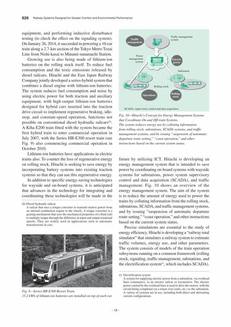
future by utilizing ICT. Hitachi is developing an energy management system that is intended to save power by coordinating on-board systems with wayside systems for substations, power system supervisory control and data acquisition (SCADA), and traffic management. Fig. 10 shows an overview of the energy management system. The aim of the system is to reduce the amount of energy used to power the trains by collating information from the rolling stock, substations, SCADA, and traffic management systems, and by issuing “suspension of automatic departure route setting,” “coast operation,” and other instructions based on the current system status.
Precise simulations are essential to the study of energy efficiency. Hitachi is developing a “railway total simulator” that simulates a railway system to estimate traffic volumes, energy use, and other parameters. The system consists of models of the train operation subsystems running on a common framework (rolling stock, signaling, traffic management, substations, and the electrification system(i), which includes SCADA).
equipment, and performing inductive disturbance testing (to check the effect on the signaling system). On January 26, 2014, it succeeded in powering a 10-car train along a 2.7-km section of the Tokyo Metro Tozai Line from Nishi-kasai to Minami-sunamachi Station.
Growing use is also being made of lithium-ion batteries on the rolling stock itself. To reduce fuel consumption and the toxic emissions released by diesel railcars, Hitachi and the East Japan Railway Company jointly developed a series-hybrid system that combines a diesel engine with lithium-ion batteries. The system reduces fuel consumption and noise by using electric power for both traction and auxiliary equipment, with high-output lithium-ion batteries designed for hybrid cars inserted into the traction drive circuit to implement regenerative braking, idle-stop, and constant-speed operation, functions not possible on conventional diesel hydraulic railcars(h). A Kiha E200 train fitted with the system became the first hybrid train to enter commercial operation in July 2007, with the Series HB-E300 resort train (see Fig. 9) also commencing commercial operation in October 2010.
Lithium-ion batteries have applications in electric trains also. To counter the loss of regenerative energy on rolling stock, Hitachi is seeking to save energy by incorporating battery systems into existing traction systems so that they can use this regenerative energy.
In addition to specific energy-saving technologies for wayside and on-board systems, it is anticipated that advances in the technology for integrating and coordinating these technologies will be made in the
(h) Diesel hydraulic railcar A railcar that uses a torque converter to transmit motive power from
an internal combustion engine to the wheels. A torque converter is a gearing mechanism that uses the mechanical properties of a fluid (oil) to multiply torque through the difference in input and output rotational speeds. They are widely used in applications such as automatic transmissions in cars.
(i) Electrification system A system for supplying electric power from a substation, via overhead
lines (catenaries), to an electric railcar or locomotive. The electric power carried by the overhead lines is used to drive the motors, with the circuit being completed via a return wire (rails, etc.) to the substation. A variety of systems are in use, including both direct and alternating current configurations.
Fig. 9—Series HB-E300 Resort Train.15.2 kWh of lithium-ion batteries are installed on top of each car.
Trafficmanagement
Electricpower
Operations Rollingstock
Traffic management system
Powermanagement
system
Substation
Rolling stock
Fig. 10—Hitachi’s Concept for Energy Management Systems that Coordinate On and Off-train Systems.The system reduces energy use by collating information from rolling stock, substations, SCADA systems, and traffic management systems, and by issuing “suspension of automatic departure route setting,” “coast operation,” and other instructions based on the current system status.
SCADA: supervisory control and data acquisition
Hitachi Review Vol. 63 (2014), No. 10 627
- 19 -
DEVELOPMENT OF TECHNOLOGIES TO
SATISFY EXPECTATIONS PLACED ON
RAILWAYS
Factors such as the growing severity of global environmental problems are driving higher expectations for railway systems throughout the world. While transportation operators are developing a variety of technologies to help create a sustainable society, there is a need for ongoing technical development to further enhance the inherent advantage that railways have of imposing a low load on the environment. In addition to safe and reliable operation, it is also important to develop technologies that will make railways more attractive to passengers, such as through the use of ICT.
As a total system integrator of railway systems, Hitachi seeks to satisfy these expectations. Its aim is to combine technologies from across the companies of the Hitachi Group to create railway systems that deliver even greater comfort and environmental performance.
REFERENCE
(1) Y. Yokosuka et al., “Development of Cutting-edge Railway Systems that Satisfy Social Needs,” Hitachi Review 61, pp.289 – 295 (Dec. 2012).
Proposals for saving energy on a particular line can be developed by combining these models and optimizing control.
Understanding how energy is used in a railway system is also essential to the study of energy efficiency. Accordingly, Hitachi has undertaken a joint study of energy use with Okinawa Urban Monorail Inc. An analysis of the effect on energy consumption of using or not using cruise operation (in the latter case, the speed was operated manually by engaging and disengaging the notch setting) found that manual operation used 5% less energy. In operational trials in which trains were or were not allowed to draw traction power simultaneously, a comparison of the energy supplied by the substations found a difference of 10% or more between modes. It was concluded from these results that there is still scope for further improving energy efficiency by adjusting train speed patterns. It was also concluded that energy could be saved by preventing trains from drawing traction power simultaneously. Meanwhile the accuracy of the railway total simulator was assessed based on measurements from the operational trials, indicating that it is able to predict rolling stock energy to within 4% of the measured value. In the future, Hitachi plans to use the railway total simulator to offer a variety of energy saving measures.
Yoshimitsu Nakazawa
Transport Management Systems & Solution Department, Rail Systems Company, Hitachi, Ltd. He is currently engaged in the coordination of railway system engineering.
Fujihiko Yokose
R&D Planning Office, Corporate Development & Strategy Division, Rail Systems Company, Hitachi, Ltd. He is currently engaged in the coordination of railway technology development.
Shigenori Iwamura
Rolling Stock Engineering Department, Rolling Stock Systems Division, Transportation Systems, Rail Systems Company, Hitachi, Ltd. He is currently engaged in the system engineering of railway cars.
ABOUT THE AUTHORS
628 Hitachi Review Vol. 63 (2014), No. 10
- 20 -
Featured Articles
Improvements to Environmental Performance and Comfort
of Rolling Stock
Takashi Yoshida
Yuta Kawaguchi
Naoji Ueki
Kazuki Okamura
Tokuichirou Oku
Kenji Okuma
OVERVIEW: As a rolling stock manufacturer, Hitachi develops a wide range of railway cars for use in everything from high-speed trains such as the Shinkansen to commuter trains. To provide the Shinkansen with an interior that passengers will find comfortable even during long trips, work by Hitachi includes the adoption of active suspension to prevent the transmission of vibrations through the floor and the use of fittings designed to ensure barrier-free accessibility. On commuter trains, Hitachi uses equipment that reduces power consumption, including LED headlights. Hitachi is also seeking to make further improvements in environmental performance and comfort, with development work that includes adapting the UD seats used at public and medical institutions for use on trains.
INTRODUCTION
RAILWAYS have received attention in recent years for
being a form of public transportation with low energy
consumption.
Hitachi supplies rolling stock aimed at reducing the
load on the environment by building high-speed trains
such as the Shinkansen and commuter trains developed
under the brand name “A-train” from lightweight
aluminum alloy.
To meet the demand in recent years for further
improvements in environmental performance and
comfort, Hitachi is working on developments for both
high-speed and commuter rolling stock.
This article describes what Hitachi is doing to
improve the environmental performance and comfort
of both high-speed and commuter trains.
TECHNOLOGY DEVELOPMENT FOR HIGH-
SPEED SHINKANSEN ROLLING STOCK
High-speed Shinkansen rolling stock plays an
essential role in long-haul travel in Japan, and major
advances have been made in the punctuality, comfort,
and convenience of travel by Shinkansen. Several
new technologies are used on the latest high-speed
Shinkansen rolling stock, not only for the basic
performance factors of running and stopping, but also
for various other objectives, including minimizing
internal and external noise, minimizing vibration,
improving energy efficiency, reducing size and weight,
and making the trains easier to maintain.
Latest High-speed Shinkansen Rolling
Stock
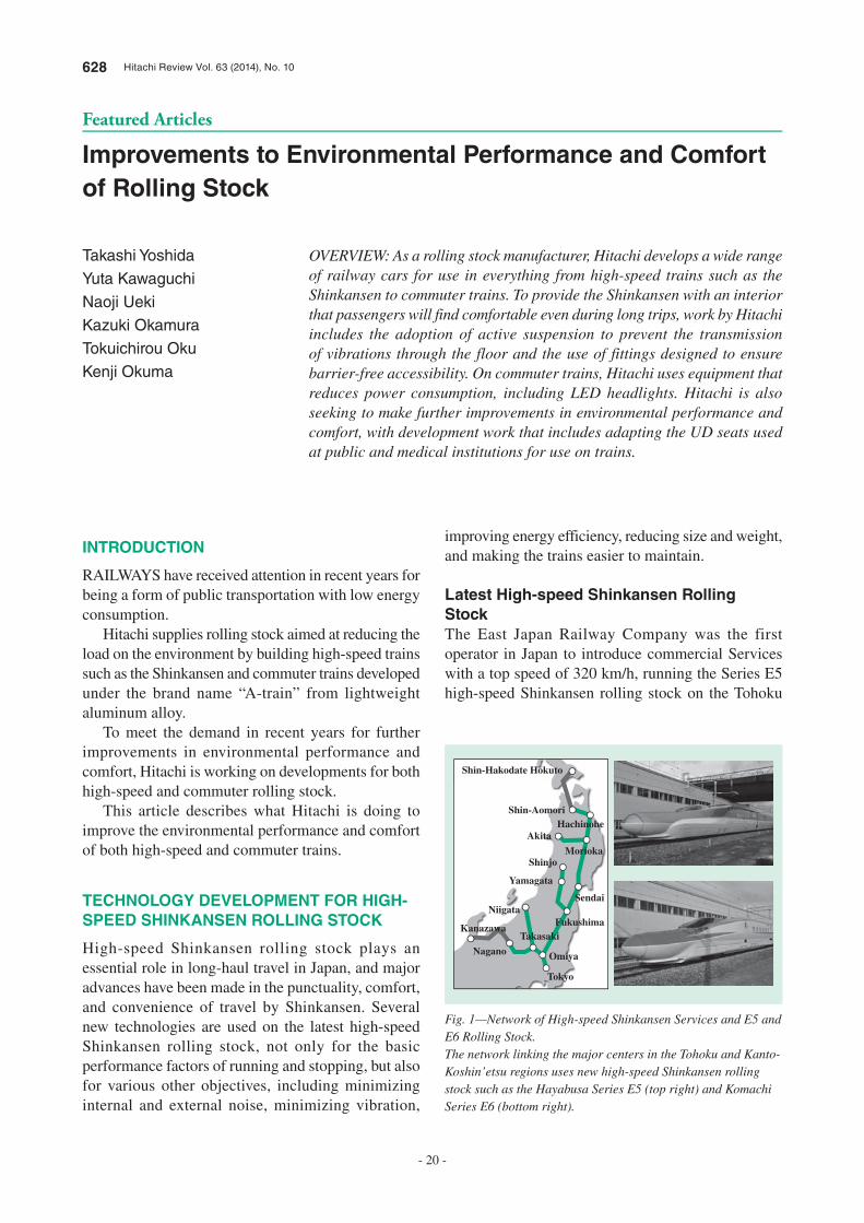
The East Japan Railway Company was the first
operator in Japan to introduce commercial Services
with a top speed of 320 km/h, running the Series E5
high-speed Shinkansen rolling stock on the Tohoku
Shin-Hakodate Hokuto
Shin-AomoriHachinohe
Akita
MoriokaShinjo
Yamagata
SendaiNiigata
Fukushima
Omiya
Tokyo
Takasaki
Nagano
Kanazawa
Fig. 1—Network of High-speed Shinkansen Services and E5 and E6 Rolling Stock.The network linking the major centers in the Tohoku and Kanto-Koshin’etsu regions uses new high-speed Shinkansen rolling stock such as the Hayabusa Series E5 (top right) and Komachi Series E6 (bottom right).
Hitachi Review Vol. 63 (2014), No. 10 629
- 21 -
Shinkansen and the Series E6 on the Akita Shinkansen
(see Fig. 1).
For the commencement of Hokuriku Shinkansen
services to Kanazawa in March 2015, the East Japan
Railway Company and West Japan Railway Company
also plan to introduce the Series E7 and W7 high-
speed Shinkansen rolling stock which has a top speed
in commercial operation of 260 km/h. The Hokkaido
Railway Company, meanwhile, plans to introduce
Series H5 high-speed Shinkansen rolling stock at the
commencement of Hokkaido Shinkansen services to
Shin-Hakodate Hokuto in March 2016. The Hokkaido
Shinkansen has a planned top speed in commercial
operation of 260 km/h, with speeds of 140 km/h
expected to be used on sections of track that are shared
with commuter lines, such as the Seikan Tunnel.
Latest Technology for High-speed
Shinkansen Rolling Stock
The latest high-speed Shinkansen rolling stock
incorporates a variety of leading-edge technologies.
The Series E5 and E6 are long-nosed models to
cope with their top speed in commercial operation of
320 km/h, with the Series H5 also expected to use the
same nose design. The Series E7 and W7 have a top
speed in commercial operation of 260 km/h.
Recognizing that the latest high-speed Shinkansen
rolling stock is used for long journeys, it is fitted
with active suspension to ensure ride comfort in the
passenger compartment by preventing the transmission
of vibrations through the floor when traveling at high
speed.
The Series E5 and other high-speed Shinkansen
rolling stock are designed to have superior deceleration,
with improved brake performance to ensure that they
can be brought to a stop more quickly than existing
models in the event of an earthquake. To deal with
earthquakes or similar emergencies, emergency
stop performance has also been improved by fitting
high-speed Shinkansen rolling stock with devices for
detecting a loss of voltage on the catenary so that they
can be brought to a stop more quickly when such a
power outage is detected.
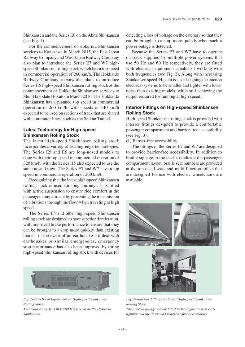
Because the Series E7 and W7 have to operate
on track supplied by multiple power systems that
use 50 Hz and 60 Hz respectively, they are fitted
with electrical equipment capable of working with
both frequencies (see Fig. 2). Along with increasing
Shinkansen speed, Hitachi is also designing the traction
electrical systems to be smaller and lighter with lower
noise than existing models, while still achieving the
output required for running at high speed.
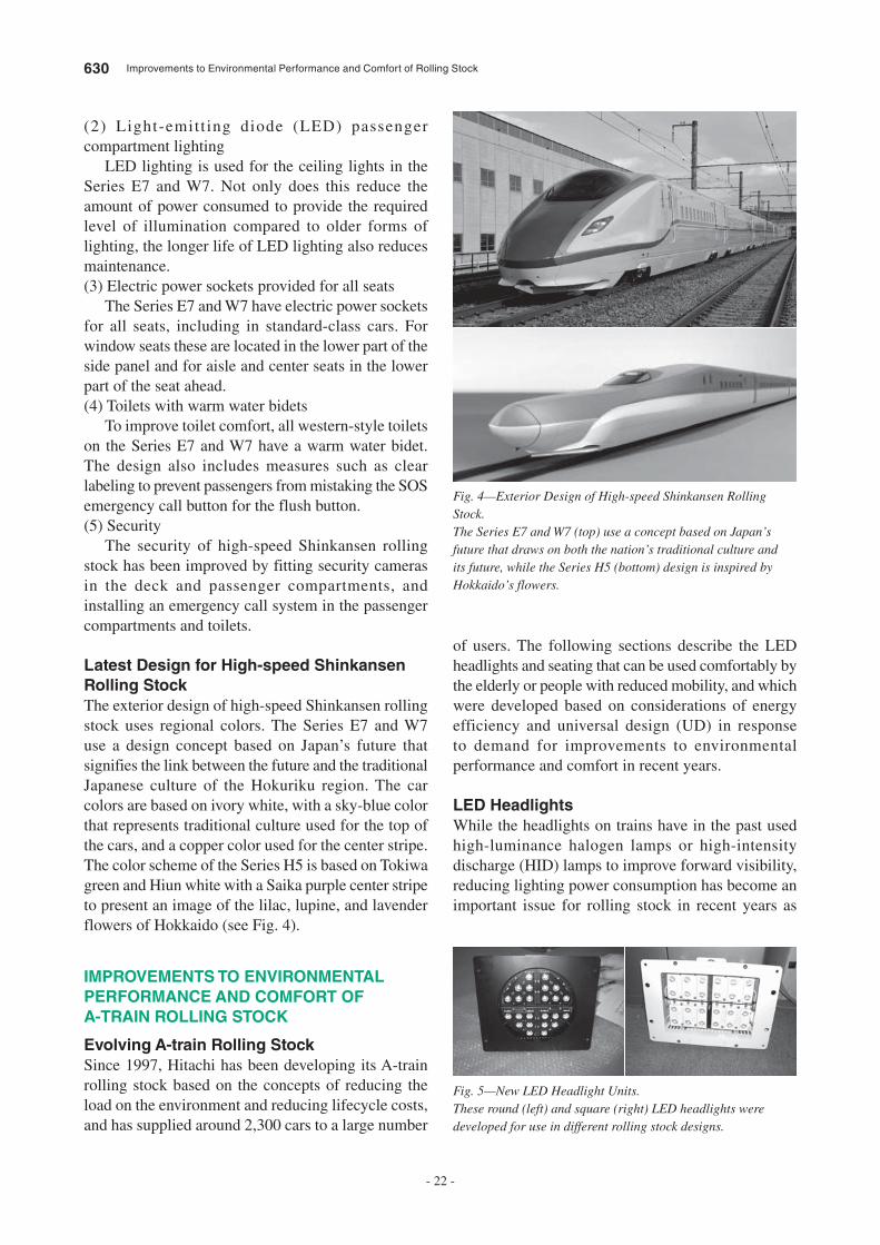
Interior Fittings on High-speed Shinkansen
Rolling Stock
High-speed Shinkansen rolling stock is provided with
interior fittings designed to provide a comfortable
passenger compartment and barrier-free accessibility
(see Fig. 3).
(1) Barrier-free accessibility
The fittings in the Series E7 and W7 are designed
to provide barrier-free accessibility. In addition to
braille signage in the deck to indicate the passenger
compartment layout, braille seat numbers are provided
at the top of all seats and multi-function toilets that
are designed for use with electric wheelchairs are
available.
Fig. 2—Electrical Equipment on High-speed Shinkansen Rolling Stock.This main converter (50 Hz/60 Hz) is used on the Hokuriku Shinkansen.
Fig. 3—Interior Fittings on Latest High-speed Shinkansen Rolling Stock.The internal fittings use the latest technologies such as LED lighting and are designed for barrier-free accessibility.
630 Improvements to Environmental Performance and Comfort of Rolling Stock
- 22 -
(2) Light-emitt ing diode (LED) passenger
compartment lighting
LED lighting is used for the ceiling lights in the
Series E7 and W7. Not only does this reduce the
amount of power consumed to provide the required
level of illumination compared to older forms of
lighting, the longer life of LED lighting also reduces
maintenance.
(3) Electric power sockets provided for all seats
The Series E7 and W7 have electric power sockets
for all seats, including in standard-class cars. For
window seats these are located in the lower part of the
side panel and for aisle and center seats in the lower
part of the seat ahead.
(4) Toilets with warm water bidets
To improve toilet comfort, all western-style toilets
on the Series E7 and W7 have a warm water bidet.
The design also includes measures such as clear
labeling to prevent passengers from mistaking the SOS
emergency call button for the flush button.
(5) Security
The security of high-speed Shinkansen rolling
stock has been improved by fitting security cameras
in the deck and passenger compartments, and
installing an emergency call system in the passenger
compartments and toilets.
Latest Design for High-speed Shinkansen
Rolling Stock
The exterior design of high-speed Shinkansen rolling
stock uses regional colors. The Series E7 and W7
use a design concept based on Japan’s future that
signifies the link between the future and the traditional
Japanese culture of the Hokuriku region. The car
colors are based on ivory white, with a sky-blue color
that represents traditional culture used for the top of
the cars, and a copper color used for the center stripe.
The color scheme of the Series H5 is based on Tokiwa
green and Hiun white with a Saika purple center stripe
to present an image of the lilac, lupine, and lavender
flowers of Hokkaido (see Fig. 4).
IMPROVEMENTS TO ENVIRONMENTAL
PERFORMANCE AND COMFORT OF
A-TRAIN ROLLING STOCK
Evolving A-train Rolling Stock
Since 1997, Hitachi has been developing its A-train
rolling stock based on the concepts of reducing the
load on the environment and reducing lifecycle costs,
and has supplied around 2,300 cars to a large number
of users. The following sections describe the LED
headlights and seating that can be used comfortably by
the elderly or people with reduced mobility, and which
were developed based on considerations of energy
efficiency and universal design (UD) in response
to demand for improvements to environmental
performance and comfort in recent years.
LED Headlights
While the headlights on trains have in the past used
high-luminance halogen lamps or high-intensity
discharge (HID) lamps to improve forward visibility,
reducing lighting power consumption has become an
important issue for rolling stock in recent years as
Fig. 4—Exterior Design of High-speed Shinkansen Rolling Stock.The Series E7 and W7 (top) use a concept based on Japan’s future that draws on both the nation’s traditional culture and its future, while the Series H5 (bottom) design is inspired by Hokkaido’s flowers.
Fig. 5—New LED Headlight Units.These round (left) and square (right) LED headlights were developed for use in different rolling stock designs.

Hitachi Review Vol. 63 (2014), No. 10 631
- 23 -
a countermeasure to global warming, with growing
demand for the use of energy-efficient LEDs for
headlights as well as in other applications. Hitachi has
drawn on the development know-how it has derived
from interior LED lights to develop and supply LED
headlights with superior environmental performance
that are more energy-efficient and reliable, and have
a longer life (see Fig. 5).
Challenges in LED Headlight DevelopmentHeadlights are important safety equipment on trains.
Accordingly, because new headlights need to provide
better illumination and visibility than before, Hitachi
conducted comparison trials with existing headlights.
Using high-beam lights focused 150 m ahead as a
reference, sealed beam lights produced 0.75 lx or
more in the trials and HID lights produced 0.5 lx.
Accordingly, the targets for LED headlights were set
at 0.75 lx with a light intensity of 16,700 cd or better.
Table 1 lists the results of illumination measurements.
Visibility TestingBased on light distribution simulations, a light
intensity of 16,700 cd was found to correspond to
illumination of 0.75 lx, which is equal to or better
than the sealed beam and HID lights. A visibility
comparison was then performed between a prototype
built based on the simulation results and sealed beam
and HID headlights fitted in a train, confirming that the
new headlight provided better visibility (see Fig. 6).
It was also confirmed that the LED headlight
provides illumination equal to or better than sealed
beam and HID lights, with illumination of 0.78 lx
when on high-beam focused 50 m ahead.
Power ConsumptionThe LED headlights that were confirmed as providing
equivalent visibility to the existing sealed beam and
HID lights consumed 42 W/lamp (350 mA) of power
when producing 16,700 cd. The power consumption
of the existing HID lights is 250 W/lamp. That is, the
power consumption per lamp had been reduced to about
one-sixth the consumption of the existing headlights.
Development of Body-friendly UD Seats
Railway car interiors are designed with users in mind,
including priority seating for the elderly, people with
reduced mobility, and pregnant women. Typically,
although these seats have used different seat fabrics,
floor coverings, and interior panel coloring to
differentiate them from ordinary seating, the materials
and shapes have been the same as ordinary seating.
Meanwhile, sites such as medical facilities
or railway stations and other public spaces have
increasingly been adopting UD seats that are less
physically demanding and easier to use for those who
take more time to sit down or stand up, such as the
elderly and people with reduced mobility.
Recognizing that the use of UD seats would be in
keeping with the original purpose of priority seating,
which is intended for the elderly, pregnant women,
and people with reduced mobility, Hitachi conducted
a survey of UD seats used at public facilities to look at
whether they could be adapted for use in trains.
Supplier A Supplier B
Headlight type Sealed beam HID
Reference axis High-beam focused 150 m ahead
Reference illumination level 0.75 lx or better 0.5 lx
TABLE 1. Illumination Measurements
The table lists the results of measuring the illumination provided by a variety of headlights.
HID: high intensity discharge
Upwards: Dark
Upwards: Light
Nearby: DarkNearby: Light
Nearby: LightNearby: Light
Distant: Light
Distant: Light
Distant: Light
Distant: Dark
High beam
Sealed beam
LED headlight
Low beam High beam
HID
LED headlight
Low beam
Nearby: Light
Nearby: Light
Upwards: Dark
Nearby: Dark
Distant: Light
Distant: Light
Nearby: Light
Upwards: Light
Fig. 6—Comparison of Visibility Provided by LED Headlights.The photographs show the results of visibility testing of sealed beam, HID, and LED headlights performed using an actual train.
632 Improvements to Environmental Performance and Comfort of Rolling Stock
- 24 -
• People for whom sitting down and standing up are
an effort
• Pregnant women
• People of short stature
Next, in preparation for commercial production,
the seats were fitted in a train to assess and verify their
performance in practice.
CONCLUSIONS
This article has described the work being done by
Hitachi on the latest technologies and universal
design for the Shinkansen, on improvements to the
environmental performance of LED headlights, and
on measures for enhancing comfort for a diverse range
of passengers by introducing UD seats in its A-train
rolling stock.
There will continue to be strong demand for
improving the environmental performance and
comfort of rolling stock in the future. Hitachi intends
to continue being proactive about identifying customer
needs and working on further improvements to
environmental performance and comfort.
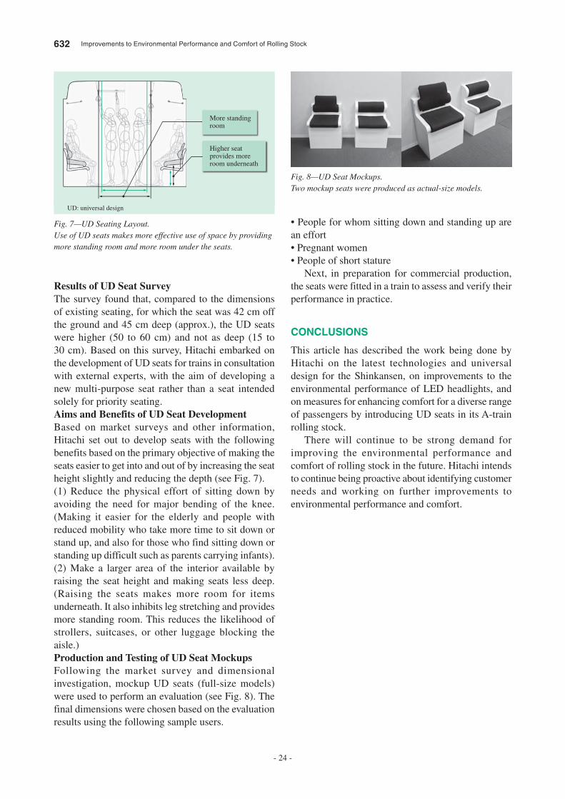
Results of UD Seat SurveyThe survey found that, compared to the dimensions
of existing seating, for which the seat was 42 cm off
the ground and 45 cm deep (approx.), the UD seats
were higher (50 to 60 cm) and not as deep (15 to
30 cm). Based on this survey, Hitachi embarked on
the development of UD seats for trains in consultation
with external experts, with the aim of developing a
new multi-purpose seat rather than a seat intended
solely for priority seating.
Aims and Benefits of UD Seat DevelopmentBased on market surveys and other information,
Hitachi set out to develop seats with the following
benefits based on the primary objective of making the
seats easier to get into and out of by increasing the seat
height slightly and reducing the depth (see Fig. 7).
(1) Reduce the physical effort of sitting down by
avoiding the need for major bending of the knee.
(Making it easier for the elderly and people with
reduced mobility who take more time to sit down or
stand up, and also for those who find sitting down or
standing up difficult such as parents carrying infants).
(2) Make a larger area of the interior available by
raising the seat height and making seats less deep.
(Raising the seats makes more room for items
underneath. It also inhibits leg stretching and provides
more standing room. This reduces the likelihood of
strollers, suitcases, or other luggage blocking the
aisle.)
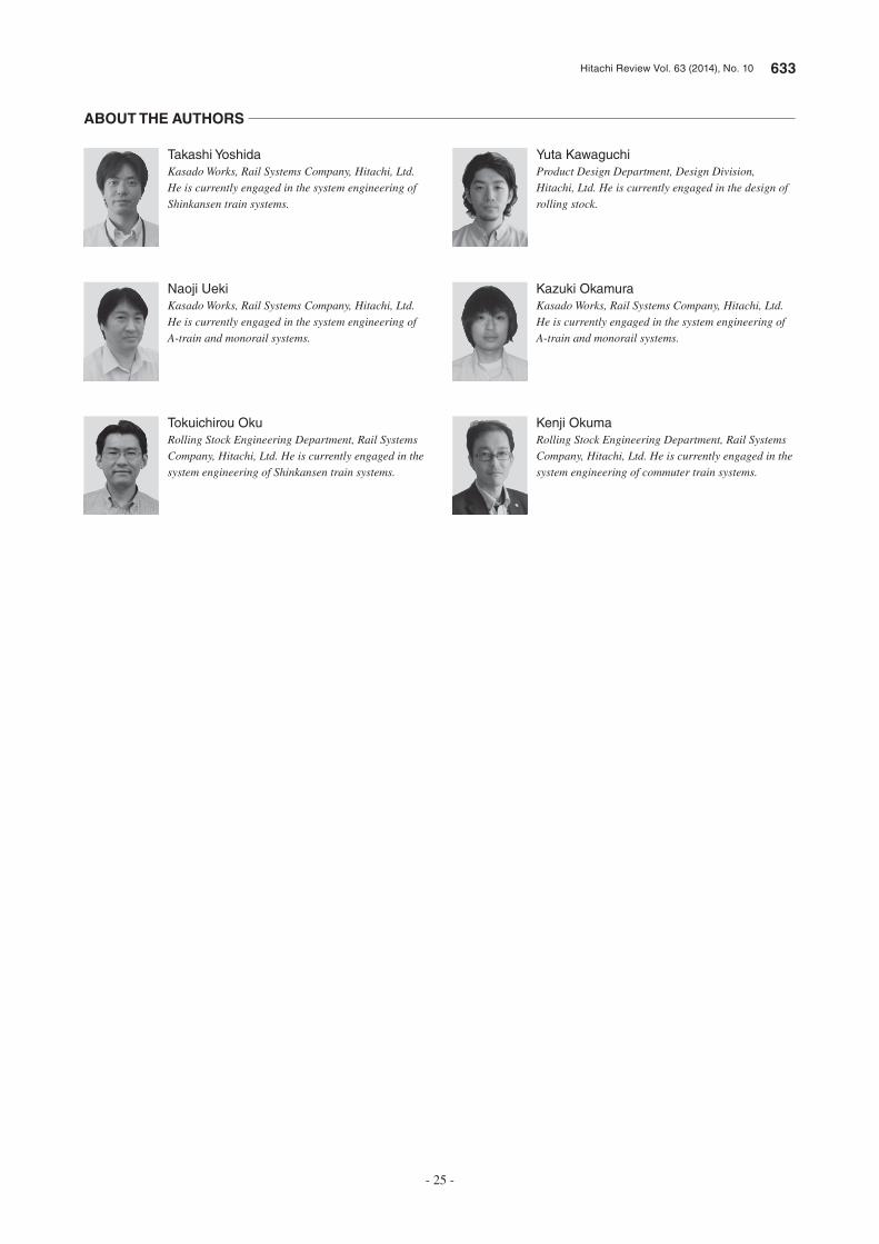
Production and Testing of UD Seat MockupsFollowing the market survey and dimensional
investigation, mockup UD seats (full-size models)
were used to perform an evaluation (see Fig. 8). The
final dimensions were chosen based on the evaluation
results using the following sample users.
More standing room
Higher seat provides more room underneath
Fig. 7—UD Seating Layout.Use of UD seats makes more effective use of space by providing more standing room and more room under the seats.
UD: universal design
Fig. 8—UD Seat Mockups.Two mockup seats were produced as actual-size models.
Hitachi Review Vol. 63 (2014), No. 10 633
- 25 -
Yuta Kawaguchi
Product Design Department, Design Division, Hitachi, Ltd. He is currently engaged in the design of rolling stock.
Kazuki Okamura
Kasado Works, Rail Systems Company, Hitachi, Ltd. He is currently engaged in the system engineering of A-train and monorail systems.
Kenji Okuma
Rolling Stock Engineering Department, Rail Systems Company, Hitachi, Ltd. He is currently engaged in the system engineering of commuter train systems.
Takashi Yoshida
Kasado Works, Rail Systems Company, Hitachi, Ltd. He is currently engaged in the system engineering of Shinkansen train systems.
Naoji Ueki
Kasado Works, Rail Systems Company, Hitachi, Ltd. He is currently engaged in the system engineering of A-train and monorail systems.
Tokuichirou Oku
Rolling Stock Engineering Department, Rail Systems Company, Hitachi, Ltd. He is currently engaged in the system engineering of Shinkansen train systems.
ABOUT THE AUTHORS
634 Hitachi Review Vol. 63 (2014), No. 10
- 26 -
Featured Articles
Rolling Stock System Technologies Underpinning the Next
Generation of Railways
Kazuo Tokuyama
Takashi Kaneko
Masahiro Fujiwara
Keishi Suzuki
OVERVIEW: Hitachi is focusing on technological developments aimed at satisfying the diverse requirements for the next generation of railway systems. In the field of battery-based systems, Hitachi has developed a variety of systems such as a battery-powered drive system. For traction drive systems, Hitachi has been utilizing the characteristics of SiC hybrid modules to improve energy efficiency. Its work on rolling stock control systems includes the development of systems that assist train crew in order to drive trains with higher energy efficiency. Meanwhile, in the field of safety equipment, Hitachi is developing a millimeter-wave radar speed sensing module, a fixed-point stopping control system with an automatic learning function, and other safety devices intended to improve operational safety and reliability. Through the coordinated operation of these systems, Hitachi seeks to improve environmental value (energy efficiency), social value (reliable operation), and commercial value (maintenance).
INTRODUCTION
AMONG the circumstances surrounding the next generation of railway systems, three particular issues are: (1) energy problems, (2) an aging population and falling birth rate, and (3) the improvement of operational safety and reliability. Dealing with energy problems requires technologies for reducing electric power consumption to cope with major increases in the price of electric power, increasing scarcity of fossil fuels, and measures for preventing global warming. Dealing with the aging population involves the transfer of operation and maintenance techniques that utilize information and communication technology (ICT) in response to the anticipated loss of experienced staff and the fall in the number of people able to take their place. To improve operational safety and reliability, meanwhile, stations are installing safety barriers on platforms. This creates a need for trains to control accurately the point where they stop, even under different braking conditions (performance, weather, etc.).
Hitachi is developing a variety of technologies in response to these challenges.
BATTERY-BASED SYSTEMS
There has been growing interest in recent years in technologies that install high-capacity, high-output batteries in trains to improve the energy efficiency of diesel railcars, and to make further improvements in the energy efficiency of electric trains. Hitachi is working on the development of technology that can reduce energy use by using batteries to power electric drive systems when trains are running on non-electrified sections of track, and systems that reduce power consumption by incorporating batteries into the traction drive systems to recover excess regenerative electric power or increase the amount of regenerative electric power produced.
Hybrid Drive System
To reduce fuel consumption and toxic emissions by diesel railcars, East Japan Railway Company and Hitachi have jointly developed a hybrid engine system powered by a combination of a diesel engine and generator and lithium-ion batteries. The system reduces fuel consumption and noise by using electric power for both traction and auxiliary equipment, with
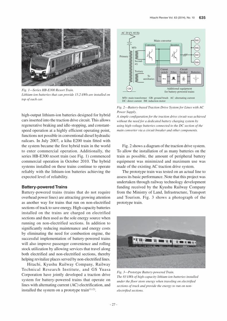
Hitachi Review Vol. 63 (2014), No. 10 635
- 27 -
high-output lithium-ion batteries designed for hybrid cars inserted into the traction drive circuit. This allows regenerative braking and idle-stopping, and constant-speed operation at a highly efficient operating point, functions not possible in conventional diesel hydraulic railcars. In July 2007, a kiha E200 train fitted with the system became the first hybrid train in the world to enter commercial operation. Additionally, the series HB-E300 resort train (see Fig. 1) commenced commercial operation in October 2010. The hybrid systems installed on these trains continue to operate reliably with the lithium-ion batteries achieving the expected level of reliability.
Battery-powered Trains
Battery-powered trains (trains that do not require overhead power lines) are attracting growing attention as another way for trains that run on non-electrified sections of track to save energy. High-capacity batteries installed on the trains are charged on electrified sections and then used as the sole energy source when running on non-electrified sections. In addition to significantly reducing maintenance and energy costs by eliminating the need for combustion engine, the successful implementation of battery-powered trains will also improve passenger convenience and rolling stock utilization by allowing services that travel along both electrified and non-electrified sections, thereby helping revitalize places served by non-electrified lines.
Hitachi, Kyushu Railway Company, Railway Technical Research Institute, and GS Yuasa Corporation have jointly developed a traction drive system for battery-powered trains that operate on lines with alternating current (AC) electrification, and installed the system on a prototype train(1) (2).
Fig. 2 shows a diagram of the traction drive system. To allow the installation of as many batteries on the train as possible, the amount of peripheral battery equipment was minimized and maximum use was made of the existing AC traction drive system.
The prototype train was tested on an actual line to assess its basic performance. Note that this project was undertaken through railway technology development funding received by the Kyushu Railway Company from the Ministry of Land, Infrastructure, Transport and Tourism. Fig. 3 shows a photograph of the prototype train.
Fig. 1—Series HB-E300 Resort Train.Lithium-ion batteries that can provide 15.2 kWh are installed on top of each car.
Fig. 2—Battery-based Traction Drive System for Lines with AC Power Supply.A simple configuration for the traction drive circuit was achieved without the need for a dedicated battery charging system by using high-voltage batteries connected to the DC section of the main converter via a circuit breaker and other components.
IM4
IM3
IM2Converter Inverter
Cutoutswitch
Toauxiliaries
Tertiary
Second-ary
Primary
MTr
AC 20 kV, 60 Hz
GB
FilterCircuitbreaker Batteries
Main converter
Additional equipmentfor battery-powered trains
IM1
MTr: main transformer GB: ground brush AC: alternating current DC: direct current IM: induction motor
Fig. 3—Prototype Battery-powered Train.The 83 kWh of high-capacity lithium-ion batteries installed under the floor store energy when traveling on electrified sections of track and provide the energy to run on non-electrified sections.
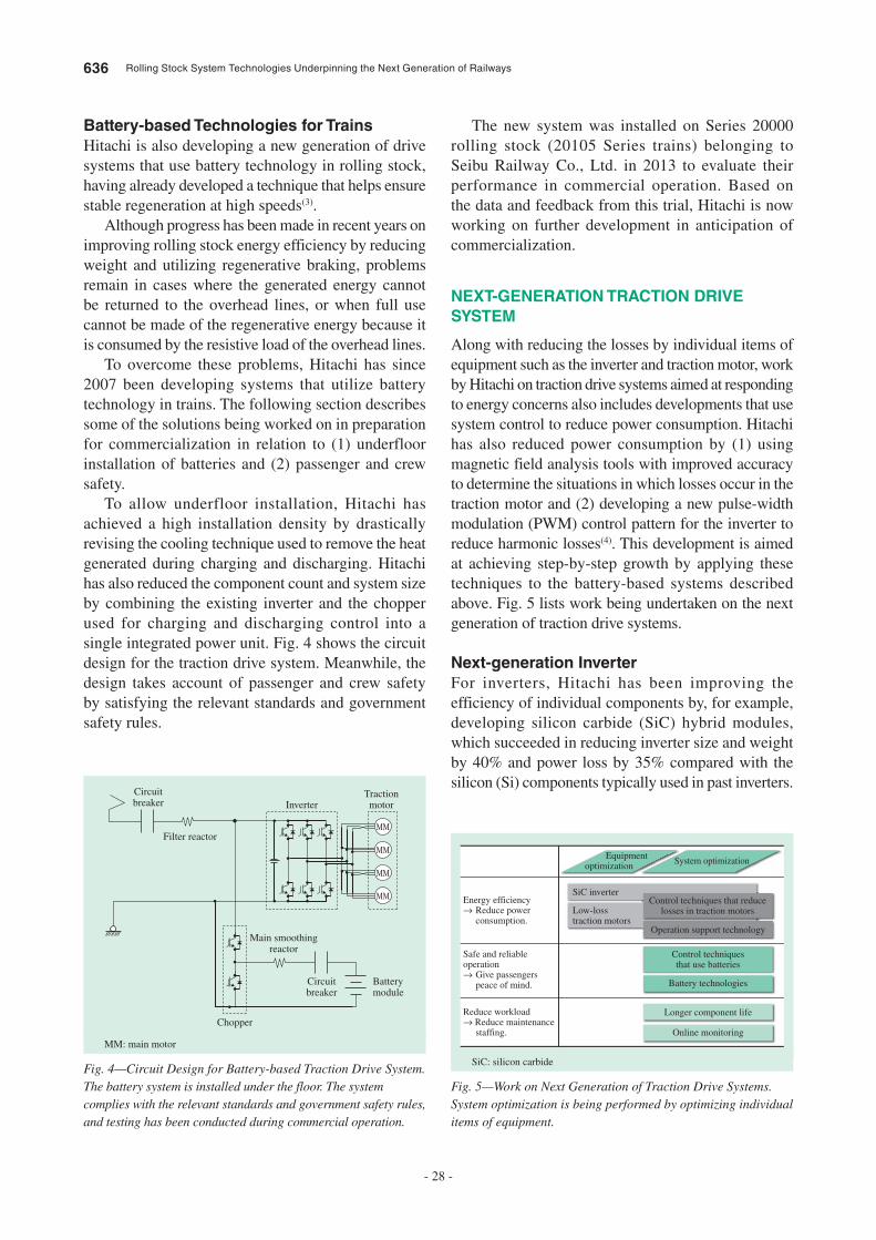
636 Rolling Stock System Technologies Underpinning the Next Generation of Railways
- 28 -
Battery-based Technologies for Trains
Hitachi is also developing a new generation of drive systems that use battery technology in rolling stock, having already developed a technique that helps ensure stable regeneration at high speeds(3).
Although progress has been made in recent years on improving rolling stock energy efficiency by reducing weight and utilizing regenerative braking, problems remain in cases where the generated energy cannot be returned to the overhead lines, or when full use cannot be made of the regenerative energy because it is consumed by the resistive load of the overhead lines.
To overcome these problems, Hitachi has since 2007 been developing systems that utilize battery technology in trains. The following section describes some of the solutions being worked on in preparation for commercialization in relation to (1) underfloor installation of batteries and (2) passenger and crew safety.
To allow underfloor installation, Hitachi has achieved a high installation density by drastically revising the cooling technique used to remove the heat generated during charging and discharging. Hitachi has also reduced the component count and system size by combining the existing inverter and the chopper used for charging and discharging control into a single integrated power unit. Fig. 4 shows the circuit design for the traction drive system. Meanwhile, the design takes account of passenger and crew safety by satisfying the relevant standards and government safety rules.
The new system was installed on Series 20000 rolling stock (20105 Series trains) belonging to Seibu Railway Co., Ltd. in 2013 to evaluate their performance in commercial operation. Based on the data and feedback from this trial, Hitachi is now working on further development in anticipation of commercialization.
NEXT-GENERATION TRACTION DRIVE
SYSTEM
Along with reducing the losses by individual items of equipment such as the inverter and traction motor, work by Hitachi on traction drive systems aimed at responding to energy concerns also includes developments that use system control to reduce power consumption. Hitachi has also reduced power consumption by (1) using magnetic field analysis tools with improved accuracy to determine the situations in which losses occur in the traction motor and (2) developing a new pulse-width modulation (PWM) control pattern for the inverter to reduce harmonic losses(4). This development is aimed at achieving step-by-step growth by applying these techniques to the battery-based systems described above. Fig. 5 lists work being undertaken on the next generation of traction drive systems.
Next-generation Inverter
For inverters, Hitachi has been improving the efficiency of individual components by, for example, developing silicon carbide (SiC) hybrid modules, which succeeded in reducing inverter size and weight by 40% and power loss by 35% compared with the silicon (Si) components typically used in past inverters.
Circuitbreaker
Circuitbreaker
Main smoothingreactor
Chopper
Batterymodule
Filter reactor
InverterTractionmotor
MM
MM
MM
MM
Fig. 4—Circuit Design for Battery-based Traction Drive System.The battery system is installed under the floor. The system complies with the relevant standards and government safety rules, and testing has been conducted during commercial operation.
MM: main motor
Energy efficiency→ Reduce power
consumption.
SiC inverter
Equipmentoptimization System optimization
Low-loss traction motors
Control techniques that reducelosses in traction motors
Operation support technology
Control techniquesthat use batteries
Battery technologies
Longer component life
Online monitoring
Reduce workload→ Reduce maintenance
staffing.
Safe and reliable operation→ Give passengers
peace of mind.
Fig. 5—Work on Next Generation of Traction Drive Systems.System optimization is being performed by optimizing individual items of equipment.
SiC: silicon carbide
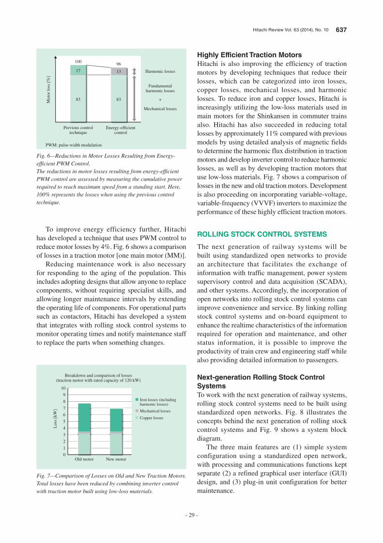
Hitachi Review Vol. 63 (2014), No. 10 637
- 29 -
To improve energy efficiency further, Hitachi has developed a technique that uses PWM control to reduce motor losses by 4%. Fig. 6 shows a comparison of losses in a traction motor [one main motor (MM)].
Reducing maintenance work is also necessary for responding to the aging of the population. This includes adopting designs that allow anyone to replace components, without requiring specialist skills, and allowing longer maintenance intervals by extending the operating life of components. For operational parts such as contactors, Hitachi has developed a system that integrates with rolling stock control systems to monitor operating times and notify maintenance staff to replace the parts when something changes.
Highly Efficient Traction Motors
Hitachi is also improving the efficiency of traction motors by developing techniques that reduce their losses, which can be categorized into iron losses, copper losses, mechanical losses, and harmonic losses. To reduce iron and copper losses, Hitachi is increasingly utilizing the low-loss materials used in main motors for the Shinkansen in commuter trains also. Hitachi has also succeeded in reducing total losses by approximately 11% compared with previous models by using detailed analysis of magnetic fields to determine the harmonic flux distribution in traction motors and develop inverter control to reduce harmonic losses, as well as by developing traction motors that use low-loss materials. Fig. 7 shows a comparison of losses in the new and old traction motors. Development is also proceeding on incorporating variable-voltage, variable-frequency (VVVF) inverters to maximize the performance of these highly efficient traction motors.
ROLLING STOCK CONTROL SYSTEMS
The next generation of railway systems will be built using standardized open networks to provide an architecture that facilitates the exchange of information with traffic management, power system supervisory control and data acquisition (SCADA), and other systems. Accordingly, the incorporation of open networks into rolling stock control systems can improve convenience and service. By linking rolling stock control systems and on-board equipment to enhance the realtime characteristics of the information required for operation and maintenance, and other status information, it is possible to improve the productivity of train crew and engineering staff while also providing detailed information to passengers.
Next-generation Rolling Stock Control
Systems
To work with the next generation of railway systems, rolling stock control systems need to be built using standardized open networks. Fig. 8 illustrates the concepts behind the next generation of rolling stock control systems and Fig. 9 shows a system block diagram.
The three main features are (1) simple system configuration using a standardized open network, with processing and communications functions kept separate (2) a refined graphical user interface (GUI) design, and (3) plug-in unit configuration for better maintenance.
Previous controltechnique
Energy-efficientcontrol
Mot
or lo
ss [
%]
Fundamentalharmonic losses
Harmonic losses
Mechanical losses
+
17
100
13
96
83 83
Fig. 6—Reductions in Motor Losses Resulting from Energy-efficient PWM Control.The reductions in motor losses resulting from energy-efficient PWM control are assessed by measuring the cumulative power required to reach maximum speed from a standing start. Here, 100% represents the losses when using the previous control technique.
PWM: pulse-width modulation
0Old motor
Los
s [k
W]
New motor
Iron losses (including harmonic losses)
Mechanical losses
Copper losses
Breakdown and comparison of losses(traction motor with rated capacity of 120 kW)
1
2
3
4
5
6
7
8
9
10
Fig. 7—Comparison of Losses on Old and New Traction Motors.Total losses have been reduced by combining inverter control with traction motor built using low-loss materials.
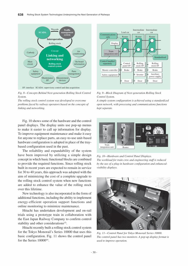
638 Rolling Stock System Technologies Underpinning the Next Generation of Railways
- 30 -
Fig. 10 shows some of the hardware and the control panel displays. The display units use pop-up menus to make it easier to call up information for display. To improve equipment maintenance and make it easy for anyone to replace parts, an easy-to-use unit-based hardware configuration is adopted in place of the tray-based configuration used in the past.
The reliability and expandability of the system have been improved by utilizing a simple design concept in which basic functional blocks are combined to provide the required functions. Since rolling stock built in recent years are expected to remain in service for 30 to 40 years, this approach was adopted with the aim of minimizing the cost of a complete upgrade to the rolling stock control system when new functions are added to enhance the value of the rolling stock over this lifetime.
New technology is also incorporated in the form of additional functions, including the ability to implement energy-efficient operation support functions and online monitoring to minimize maintenance.
Hitachi has undertaken development and on-rail trials using a prototype train in collaboration with the East Japan Railway Company to confirm control stability and other considerations(5).
Hitachi recently built a rolling stock control system for the Tokyo Monorail’s Series 10000 that uses this basic configuration. Fig. 11 shows the control panel for the Series 10000(6).
SCADATraffic
managementsystem
Wayside
Interoperation
Rolling stock
Concept
Rolling stockcontrol system
Linking andnetworking
Carbody Airconditioning
Maincircuit
On-boardinformation
Safetyequipment
Partsmanagement
MaintenanceI/F
Measurementdevices
Fig. 8—Concepts Behind Next-generation Rolling Stock Control System.The rolling stock control system was developed to overcome problems faced by railway operators based on the concepts of linking and networking.
I/F: interface SCADA: supervisory control and data acquisition
Rollingstock I/F
Brake
Door
Inverter
Rollingstock I/F
Brake
Door
Auxiliarypower supply
Controlpanel I/F
BrakeMaster controller
Trainintegration unit
Control handledseparately
Standardized
Display
Lead car
Router Router Router
Intermediatecar
Intermediatecar
Safety equipment
Door
Communicationsonly
Fig. 9—Block Diagram of Next-generation Rolling Stock Control System.A simple system configuration is achieved using a standardized open network, with processing and communications functions kept separate.
Trainintegration unit Router
Fig. 10—Hardware and Control Panel Displays.The workload for train crew and engineering staff is reduced by the use of a plug-in hardware configuration and enhanced-visibility displays.
Fig. 11—Control Panel for Tokyo Monorail Series 10000.The control panel has two monitors. A pop-up display format is used to improve operation.
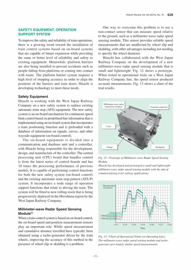
Hitachi Review Vol. 63 (2014), No. 10 639
- 31 -
One way to overcome this problem is to use a non-contact sensor that can measure speed relative to the ground, such as a millimeter-wave radar speed sensing module. This sensor provides reliable speed measurements that are unaffected by wheel slip and skidding, with other advantages including not needing to specify the wheel diameter.
Hitachi has collaborated with the West Japan Railway Company on the development of a new millimeter-wave radar speed sensing module that is small and lightweight. Fig. 12 shows a prototype. When tested in operational trials on a West Japan Railway Company line, the speed sensor produced accurate measurements. Fig. 13 shows a chart of the trial results.
SAFETY EQUIPMENT, OPERATION
SUPPORT SYSTEM
To improve the safety and reliability of train operations, there is a growing trend toward the installation of train control systems based on on-board systems that are capable of future expansion while providing the same or better level of reliability and safety as existing equipment. Meanwhile, platform barriers are also being installed to prevent accidents such as people falling from platforms or coming into contact with trains. The platform barrier system requires a high level of stopping accuracy in order to align the positions of the barriers and train doors. Hitachi is developing technology to meet these needs.
Safety Equipment
Hitachi is working with the West Japan Railway Company on a new safety system to replace existing automatic train stop (ATS) equipment. The new safety system is an on-board mechanism for continuous speed limit control based on predefined line information that is implemented using an on-board system that incorporates a train positioning function and is preloaded with a database of information on signals, curves, and other wayside equipment (on-board control).
The on-board equipment is divided into a communication and database unit and a controller, with Hitachi being responsible for the development, design, and manufacture of the controller. The central processing unit (CPU) board that handles control is from the latest series of control boards and has 10 times the processing performance of previous models. It is capable of performing control functions for both the new safety system (on-board control) and the existing automatic train stop-pattern (ATS-P) system. It incorporates a wide range of operation support functions that relate to driving the train. The system will be fitted to new rolling stock that is being progressively deployed in the Hiroshima region by the West Japan Railway Company.
Millimeter-wave Radar Speed Sensing
Module(7)
When a train control system is based on on-board control, the on-board speed and position measurement sensors play an important role. While speed measurement and cumulative distance travelled have typically been obtained using a tacho-generator driven by the train wheels, improving the accuracy of this method in the presence of wheel slip or skidding is a problem.
Millimeter-wave radartransceiver window
Flange Backplate
External connector
Case
Fig. 12—Prototype of Millimeter-wave Radar Speed Sensing Module.Hitachi has developed and prototyped a small and lightweight millimeter-wave radar speed sensing module with the aim of commercializing it for railway applications.
13:12 13:14 13:16 13:18
Time
1. Tacho-generator
Measured speed(10 km/h/div)
2. Millimeter-wave radar device 13. Millimeter-wave radar device 2
13:20 13:22 13:24
Fig. 13—Chart of Operational Trials (on Operating Line).The millimeter-wave radar speed sensing module and tacho-generator give largely similar speed measurements.

640 Rolling Stock System Technologies Underpinning the Next Generation of Railways
- 32 -
REFERENCES
(1) K. Hatakeda., “Upgrade to AC Electric Train for Battery-powered Train Operation,” Proceedings of 20th J-RAIL Symposium S3-3-5 (Dec. 2013) in Japanese.
(2) T. Kaneko et al., “Development of a Battery-powered Traction Circuit for AC Electric Trains,” Proceedings of 50th Symposium of Congress of Japan Railway Cybernetics, 524 (Nov. 2013) in Japanese.
(3) M. Shimada et al., “Energy-saving Technology for Railway Traction Systems Using Onboard Storage Batteries,” Hitachi Review 61, pp. 312–318 (Dec. 2012).
(4) T. Sakai et al., “Motor Loss Reduction Technology Utilizing PWM Control,” Proceedings of 50th Symposium of Congress of Japan Railway Cybernetics, 502 (Nov. 2013) in Japanese.
(5) A. Sobue et al., “Development of Next-generation Railway Control System (INTEROS),” Proceedings of 49th Symposium of Congress of Japan Railway Cybernetics, 502 (Nov. 2012) in Japanese.
(6) M. Higuchi et al., “Overview of Series 10000 ATI Supplied to Tokyo Monorail,” Rolling Stock and Technology No. 212 (Apr. 2014) in Japanese.
(7) Y. Iwao., “Development and Application of Millimeter-wave Radar Speed Sensing Module for Rolling Stock by Hitachi, Ltd.,” Rolling Stock and Technology No. 208 (Dec. 2013) in Japanese.
Operation Support System (Fixed-point
Stopping Control System)
The installation of platform barriers is driving growing demand for automatic train operation/train automatic stop control (ATO/TASC) operation support systems to ensure trains stop at the correct position at a station. The past practice in ATO/TASC commissioning has been to tune control parameters by trial and error based on the difference between the actual and design values for rolling stock performance during operational trials. This is both time-consuming and requires the railway operator to provide time for testing and deal with any resulting disruption.
Hitachi is developing an automatic tuning function for ATO/TASC control. This function involves collecting data from routine operation and the use of online statistical processing to determine the rolling stock performance. The results are then used as a basis for outputting brake commands to rolling stock at the appropriate timing. Use of this automatic tuning function is expected to reduce the amount of commissioning work (less time required for operational testing) and help maintain stopping accuracy by continuing to use automatic tuning (learning) on rolling stock after it enters commercial operation.
CONCLUSIONS
Hitachi supplies systems that are each being progressively improved, and is developing technology for the next generation of railway systems in response to increasingly diverse needs.
In the future, this development will utilize advances in ICT to implement interoperation with other systems, and will extend to control as well as to providing information. Hitachi intends to continue working on further technical innovations by connecting systems together so as to achieve synergies that improve economic performance for users.
ACKNOWLEDGEMENTS
The authors would like to take this opportunity to express their gratitude for the considerable effort and cooperation received from the railway companies and everyone involved in these developments.
Takashi Kaneko
Rolling Stock Electrical Systems Design Department, Mito Rail Systems Product Division, Rail Systems Company, Hitachi, Ltd. He is currently engaged in the design and development of power converters for rolling stock drive systems. Mr. Kaneko is a member of The Institute of Electrical Engineers of Japan.
Keishi Suzuki
Rolling Stock Engineering Department, Sales & Marketing Division, Rail Systems Company, Hitachi, Ltd. He is currently engaged in rolling stock system engineering.
Kazuo Tokuyama
Rolling Stock Engineering Department, Sales & Marketing Division, Rail Systems Company, Hitachi, Ltd. He is currently engaged in coordinating systems for commuter trains.
Masahiro Fujiwara
Kansai Transportation Systems Department, Rail Systems Company, Hitachi, Ltd. He is currently engaged in rolling stock system engineering.
ABOUT THE AUTHORS
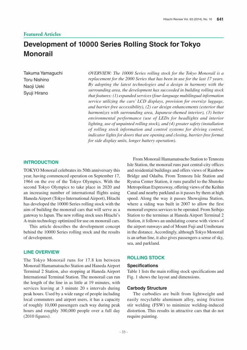
Hitachi Review Vol. 63 (2014), No. 10 641
- 33 -
Featured Articles
Development of 10000 Series Rolling Stock for Tokyo Monorail
Takuma Yamaguchi
Toru Nishino
Naoji Ueki
Syuji Hirano
OVERVIEW: The 10000 Series rolling stock for the Tokyo Monorail is a replacement for the 2000 Series that has been in use for the last 17 years. By adopting the latest technologies and a design in harmony with the surrounding area, the development has succeeded in building rolling stock that features: (1) expanded services (four-language multilingual information service utilizing the cars’ LCD displays, provision for oversize luggage, and barrier-free accessibility), (2) car design enhancements (exterior that harmonizes with surrounding area, Japanese-themed interior), (3) better environmental performance (use of LEDs for headlights and interior lighting, use of unpainted rolling stock), and (4) greater safety (installation of rolling stock information and control systems for driving control, indicator lights for doors that are opening and closing, barrier-free format for side display units, longer battery operation).
INTRODUCTION
TOKYO Monorail celebrates its 50th anniversary this
year, having commenced operation on September 17,
1964 on the eve of the Tokyo Olympics. With the
second Tokyo Olympics to take place in 2020 and
an increasing number of international flights using
Haneda Airport (Tokyo International Airport), Hitachi
has developed the 10000 Series rolling stock with the
aim of building the monorail cars that will serve as a
gateway to Japan. The new rolling stock uses Hitachi’s
A-train technology optimized for use on monorail cars.
This article describes the development concept
behind the 10000 Series rolling stock and the results
of development.
LINE OVERVIEW
The Tokyo Monorail runs for 17.8 km between
Monorail Hamamatsucho Station and Haneda Airport
Terminal 2 Station, also stopping at Haneda Airport
International Terminal Station. The monorail can run
the length of the line in as little at 19 minutes, with
services leaving at 3 minute 20 s intervals during
peak hours. Used by a wide range of people including
local commuters and airport users, it has a capacity
of roughly 10,000 passengers each way during peak
hours and roughly 300,000 people over a full day
(2010 figures).
From Monorail Hamamatsucho Station to Tennozu
Isle Station, the monorail runs past central-city offices
and residential buildings and offers views of Rainbow
Bridge and Odaiba. From Tennozu Isle Station and
Ryutsu Center Station, it runs parallel to the Shutoko
Metropolitan Expressway, offering views of the Keihin
Canal and nearby parkland as it passes by them at high
speed. Along the way it passes Showajima Station,
where a siding was built in 2007 to allow the first
monorail express services to be operated. From Seibijo
Station to the terminus at Haneda Airport Terminal 2
Station, it follows an undulating course with views of
the airport runways and of Mount Fuji and Umihotaru
in the distance. Accordingly, although Tokyo Monorail
is an urban line, it also gives passengers a sense of sky,
sea, and parkland.
ROLLING STOCK
Specifi cationsTable 1 lists the main rolling stock specifications and
Fig. 1 shows the layout and dimensions.
Carbody StructureThe carbodies are built from lightweight and
easily recyclable aluminum alloy, using friction
stir welding (FSW) to minimize welding-induced
distortion. This results in attractive cars that do not
require painting.

642 Development of 10000 Series Rolling Stock for Tokyo Monorail
- 34 -
Furthermore, because of the need to satisfy
stringent axle load limits despite the addition of
extensive new equipment not present on the old
2000 Series, including information and control
systems and inter-car connecting doors, Hitachi
reduced the weight of the new rolling stock by
developing a hybrid structure that uses a combination
of single- and double-skin sections in place of the
double-skin structure used in the A-train rolling stock.
BogiesThe bogies have a two-axle configuration with running
wheels and horizontal wheels (guide and safety
wheels).
For carbody support, in place of the swing bolster
configuration used on the previous 500 to 2000 Series,
the 10000 Series bogies have been made lighter by
using a bolsterless configuration with the carbody
supported directly by pneumatic springs mounted on
top of the bogie frame.
Whereas the previous foundation brake had one
pneumatic-hydraulic converter for each caliper,
the 10000 Series has reduced the component count
by using a series connection with each pneumatic-
hydraulic converter operating two calipers.
Maintenance work has also been reduced by
fitting wireless pressure sensors on the running tires
to provide continuous display of tire pressure on
autonomous decentralized train integrated system
(ATI) screens.
ROLLING STOCK DESIGN
Exterior DesignThe basic exterior design has a fresh feel with an
unpainted hairline finish that takes advantage of the
Parameter Specification
TypeStraddle-beam electric monorail with dual-axle bogie made of aluminum alloy
Cars per train 6 (3 cars per unit)
Capacity 76 people/car
Power system DC750 V
Rail width 800 mm
Load Axle load (max.) 90.2 kN
Performance
Acceleration: 0.97 m/s2
DecelerationNormal: 1.11 m/s2
Emergency: 1.25 m/s2
Maximum gradient 60‰
Minimum curve radius 100 m
Main motor Three-phase squirrel-cage induction motor
Control system Two-level IGBT, VVVF inverter
BrakeRegenerative brake and electrically operated electromagnetic straight brake with pneumatic-hydraulic converter
Electric air compressor Oil-free reciprocating
Signals and safety ATC/TD
Communications 150-MHz band, space-wave semi-duplex
Low-voltage power supply
124 kVA SIV (two per train)
Current collector Via contact with underside of electrified rail
Air conditioningRoof-mounted with two-stage control: 20.3 kW/unit
Emergency escape Escape chute, abseil
TABLE 1. Rolling Stock Specifications
While the specifications are based on the existing 2000 Series, a low-voltage power supply has been added to handle the addition of numerous devices.
DC: direct current IGBT: insulated-gate bipolar transistor VVVF: variable voltage variable frequency ATC/TD: automatic train control/train detection SIV: static inverter
Chute
Priority seating
Priority seatingWheelchair space Priority seating
Fig. 1—Rolling Stock Layout and Dimensions (mm).The monorail has a fixed six-cars-per-train configuration (Tc1-M1-M2-M3-M4-Tc2), with barrier-free access to the passenger compartment provided in the form of wheelchair space on the leading car and priority seating in all cars.

Hitachi Review Vol. 63 (2014), No. 10 643
- 35 -
texture of aluminum, while the sides of the cars are
coated in a film that combines green with a shading
of blue into sky blue to represent the sky, sea, and
parkland character of the surrounding area (see
Fig. 2).
The fronts of the cars have a design that embodies
the advanced features of the new rolling stock,
presenting a bold impression with black as the keynote
color, and incorporating sidelights, which is a first for
a monorail car (see Figs. 2 and 3).
The car design is also intended to be appreciated
from a variety of angles, with the Tokyo Monorail logo
appearing on the car roofs, which can be seen from
elevated sites such as the tops of buildings.
Interior DesignSince the monorail is also used by visitors from
overseas, the interior design presents a theme of
Japanese hospitality throughout, with the following
four key features (see Fig. 4).
(1) Ocean-wave pattern on seats
(2) Collision-prevention graphics on inter-car
connecting doors with distinctively Japanese icons,
such as Mount Fuji and a five-story pagoda
(3) Design of interior light-emitting diode (LED)
lights covered with a Japanese paper pattern
(4) Checkered pattern on side panels by raised-floor
seats
Additionally, glass is used for the passenger seat
side panels, luggage racks, and inter-car connecting
doors to create a functional interior with a light and
spacious feel.
SAFETY IMPROVEMENTS
Indicator Lights for Opening and Closing DoorsLights are installed above the doors to indicate when
they are opening or closing. While typically the only
function of these indicators, which are also used on
other trains and monorails, has been to flash red to
warn when the door is opening or closing, Hitachi has
developed two-color indicators (red and blue) with
three display patterns: continuously on, flashing, and
a pattern of moving lights in which all elements turn
on and then progressively turn off from the center to
the two edges. These three display patterns present
passengers with a series of escalating warnings, as
follows (see Fig. 5).
(1) As the monorail approaches a station, the indicator
above the door that will open displays the moving light
pattern in blue.
Fig. 2—TMK10000 Series Monorail Rolling Stock.The design uses a color film representing sky, sea, and parkland on the side of the cars to keep in harmony with the surroundings, with a bold black design for the front.
Fig. 3—Sidelights.The sidelights are sky blue, the representative color of the Tokyo Monorail.
Ocean-wave seat pattern
LED cover with Japanese paper pattern
Collision-prevention graphic
Checkered pattern on side panels
Fig. 4—Various Interior Designs.Since the monorail is also used by visitors from overseas, the interior design is based on Japanese motifs throughout.
LED: light-emitting diode
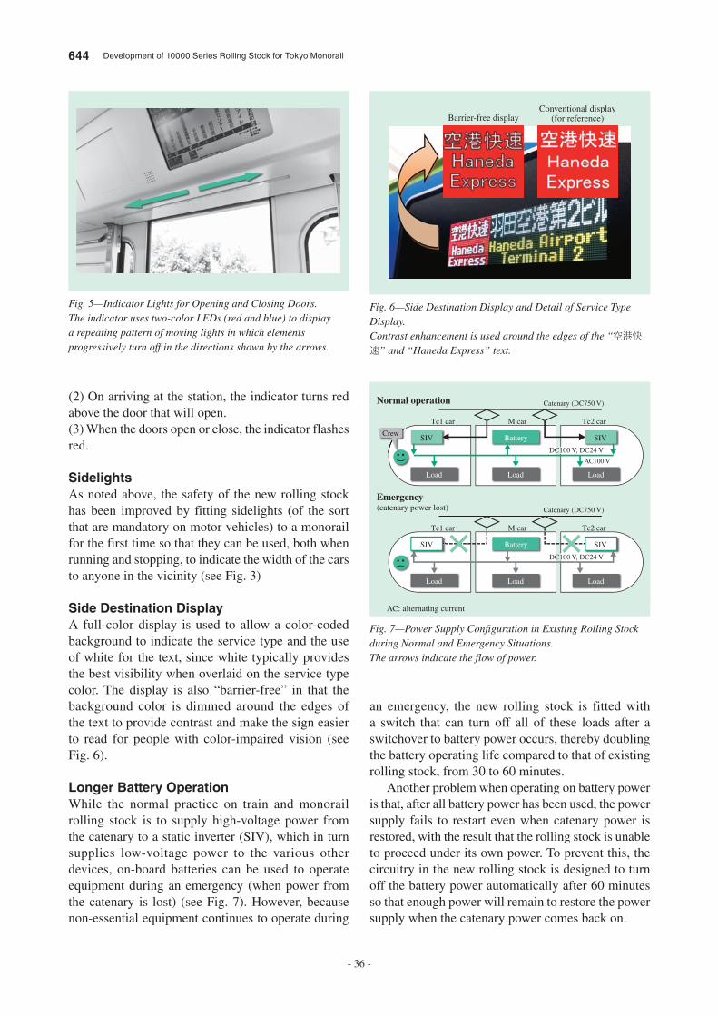
644 Development of 10000 Series Rolling Stock for Tokyo Monorail
- 36 -
(2) On arriving at the station, the indicator turns red
above the door that will open.
(3) When the doors open or close, the indicator flashes
red.
SidelightsAs noted above, the safety of the new rolling stock
has been improved by fitting sidelights (of the sort
that are mandatory on motor vehicles) to a monorail
for the first time so that they can be used, both when
running and stopping, to indicate the width of the cars
to anyone in the vicinity (see Fig. 3)
Side Destination DisplayA full-color display is used to allow a color-coded
background to indicate the service type and the use
of white for the text, since white typically provides
the best visibility when overlaid on the service type
color. The display is also “barrier-free” in that the
background color is dimmed around the edges of
the text to provide contrast and make the sign easier
to read for people with color-impaired vision (see
Fig. 6).
Longer Battery OperationWhile the normal practice on train and monorail
rolling stock is to supply high-voltage power from
the catenary to a static inverter (SIV), which in turn
supplies low-voltage power to the various other
devices, on-board batteries can be used to operate
equipment during an emergency (when power from
the catenary is lost) (see Fig. 7). However, because
non-essential equipment continues to operate during
an emergency, the new rolling stock is fitted with
a switch that can turn off all of these loads after a
switchover to battery power occurs, thereby doubling
the battery operating life compared to that of existing
rolling stock, from 30 to 60 minutes.
Another problem when operating on battery power
is that, after all battery power has been used, the power
supply fails to restart even when catenary power is
restored, with the result that the rolling stock is unable
to proceed under its own power. To prevent this, the
circuitry in the new rolling stock is designed to turn
off the battery power automatically after 60 minutes
so that enough power will remain to restore the power
supply when the catenary power comes back on.
Fig. 5—Indicator Lights for Opening and Closing Doors.The indicator uses two-color LEDs (red and blue) to display a repeating pattern of moving lights in which elements progressively turn off in the directions shown by the arrows.
Barrier-free displayConventional display
(for reference)
Fig. 6—Side Destination Display and Detail of Service Type Display.Contrast enhancement is used around the edges of the “空港快速” and “Haneda Express” text.
Crew
Tc1 car
DC100 V, DC24 V
AC100 V
Catenary (DC750 V)
M car
Battery
Load Load Load
SIV SIV
Tc2 car
Tc1 car
DC100 V, DC24 V
Catenary (DC750 V)
M car
Battery
Load Load Load
SIV SIV
Tc2 car
Normal operation
Emergency(catenary power lost)
Fig. 7—Power Supply Configuration in Existing Rolling Stock during Normal and Emergency Situations.The arrows indicate the flow of power.
AC: alternating current
Hitachi Review Vol. 63 (2014), No. 10 645
- 37 -
In the future, Hitachi intends to continue striving
to develop rolling stock that incorporates more added
value by utilizing the latest technologies and carefully
considering the design.
CONCLUSIONS
This article has described the development concept
behind the 10000 Series rolling stock for the Tokyo
Monorail and the results of development.
Toru Nishino
Rail Project Engineering Department, Rail Systems Company, Hitachi, Ltd. He is currently engaged in the development of monorail rolling stock.
Syuji Hirano
Kasado Works, Rail Systems Company, Hitachi, Ltd. He is currently engaged in the system engineering of bogies.
Takuma Yamaguchi
Kasado Works, Rail Systems Company, Hitachi, Ltd. He is currently engaged in the system engineering of commuter train and monorail systems.
Naoji Ueki
Kasado Works, Rail Systems Company, Hitachi, Ltd. He is currently engaged in the system engineering of commuter train and monorail systems.
ABOUT THE AUTHORS
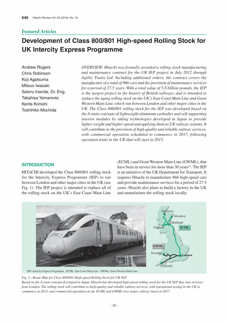
646 Hitachi Review Vol. 63 (2014), No. 10
- 38 -
Featured Articles
Development of Class 800/801 High-speed Rolling Stock for UK Intercity Express Programme
Andrew Rogers
Chris Robinson
Koji Agatsuma
Mitsuo Iwasaki
Satoru Inarida, Dr. Eng.
Takahisa Yamamoto
Kenta Konishi
Toshihiko Mochida
OVERVIEW: Hitachi was formally awarded a rolling stock manufacturing and maintenance contract for the UK IEP project in July 2012 through Agility Trains Ltd. Including additional orders, the contract covers the manufacture of a total of 866 cars and the provision of maintenance services for a period of 27.5 years. With a total value of 5.8 billion pounds, the IEP is the largest project in the history of British railways, and is intended to replace the aging rolling stock on the UK’s East Coast Main Line and Great Western Main Line, which run between London and other major cities in the UK. The Class 800/801 rolling stock for the IEP was developed based on the A-train concepts of lightweight aluminum carbodies and self-supporting interior modules by taking technologies developed in Japan to provide lighter weight and higher speed and applying them to UK railway systems. It will contribute to the provision of high-quality and reliable railway services, with commercial operation scheduled to commence in 2017, following operation trials in the UK that will start in 2015.
INTRODUCTION
HITACHI developed the Class 800/801 rolling stock for the Intercity Express Programme (IEP) to run between London and other major cities in the UK (see Fig. 1). The IEP project is intended to replace all of the rolling stock on the UK’s East Coast Main Line
(ECML) and Great Western Main Line (GWML), that have been in service for more than 30 years(1). The IEP is an initiative of the UK Department for Transport. It requires Hitachi to manufacture 866 high-speed cars and provide maintenance services for a period of 27.5 years. Hitachi also plans to build a factory in the UK and manufacture the rolling stock locally.
ECML
Aberdeen
Edinburgh
Glasgow
Plymouth
SwanseaLondon
Inverness
GWML
Fig. 1—Route Map for Class 800/801 High-speed Rolling Stock for UK IEP.Based on the A-train concept developed in Japan, Hitachi has developed high-speed rolling stock for the UK IEP that runs services from London. The rolling stock will contribute to high-quality and reliable railway services, with operational testing in the UK to commence in 2015, and commercial operation on the ECML and GWML (two major railway lines) in 2017.
IEP: Intercity Express Programme ECML: East Coast Main Line GWML: Great Western Main Line
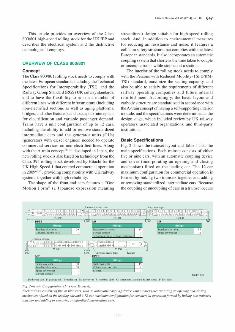
Hitachi Review Vol. 63 (2014), No. 10 647
- 39 -
This article provides an overview of the Class 800/801 high-speed rolling stock for the UK IEP and describes the electrical system and the distinctive technologies it employs.
OVERVIEW OF CLASS 800/801
ConceptThe Class 800/801 rolling stock needs to comply with the latest European standards, including the Technical Specifications for Interoperability (TSI), and the Railway Group Standard (RGS) UK railway standards, and to have the flexibility to run on a number of different lines with different infrastructure (including non-electrified sections as well as aging platforms, bridges, and other features), and to adapt to future plans for electrification and variable passenger demand. Trains have a unit configuration of up to 12 cars, including the ability to add or remove standardized intermediate cars and the generator units (GUs) (generators with diesel engines) needed to operate commercial services on non-electrified lines. Along with the A-train concept(2), (3) developed in Japan, the new rolling stock is also based on technology from the Class 395 rolling stock developed by Hitachi for the UK High Speed 1 that entered commercial operation in 2009(4), (5), providing compatibility with UK railway systems together with high reliability.
The shape of the front-end cars features a “One Motion Form” (a Japanese expression meaning
streamlined) design suitable for high-speed rolling stock. And, in addition to environmental measures for reducing air resistance and noise, it features a collision safety structure that complies with the latest European standards. It also incorporates an automatic coupling system that shortens the time taken to couple or uncouple trains while stopped at a station.
The interior of the rolling stock needs to comply with the Persons with Reduced Mobility-TSI (PRM-TSI) standard, maximize the seating capacity, and also be able to satisfy the requirements of different railway operating companies and future internal refurbishment. Accordingly, the basic layout and carbody structure are standardized in accordance with the A-train concept of having a self-supporting interior module, and the specifications were determined at the design stage, which included review by UK railway operators, associated organizations, and third-party institutions.
Basic Specifi cationsFig. 2 shows the trainset layout and Table 1 lists the main specifications. Each trainset consists of either five or nine cars, with an automatic coupling device and cover (incorporating an opening and closing mechanism) fitted on the leading car. The 12-car maximum configuration for commercial operation is formed by linking two trainsets together and adding or removing standardized intermediate cars. Because the coupling or uncoupling of cars in a trainset occurs
25,350
2535025,000
25,0001,000
Universal access toilet Bicycle storage
Universal access toilet Kitchen
Bicycle storage
Standard class seats
FittingsDPTS
Universal access toilet561
Standard class seats
FittingsMS
Space saver toilet882
Standard class seats
FittingsMS
Bicycle storage881
Preparation room for on-board retail service 1
First class seats
FittingsMC
Standard class seats3038
Space saver toilet 1Bicycle storage 1
First class seats
FittingsDPTF
Universal access toilet151
Kitchen 1
1,000
1,000 500
Units: mm
500
25,000
Fig. 2—Train Configuration (Five-car Trainset).Each trainset consists of five or nine cars, with an automatic coupling device with a cover (incorporating an opening and closing mechanism) fitted on the leading car and a 12-car maximum configuration for commercial operation formed by linking two trainsets together and adding or removing standardized intermediate cars.
D: driving cab P: pantograph T: trailer car M: motor car S: standard class C: composite (standard & first class) F: first class
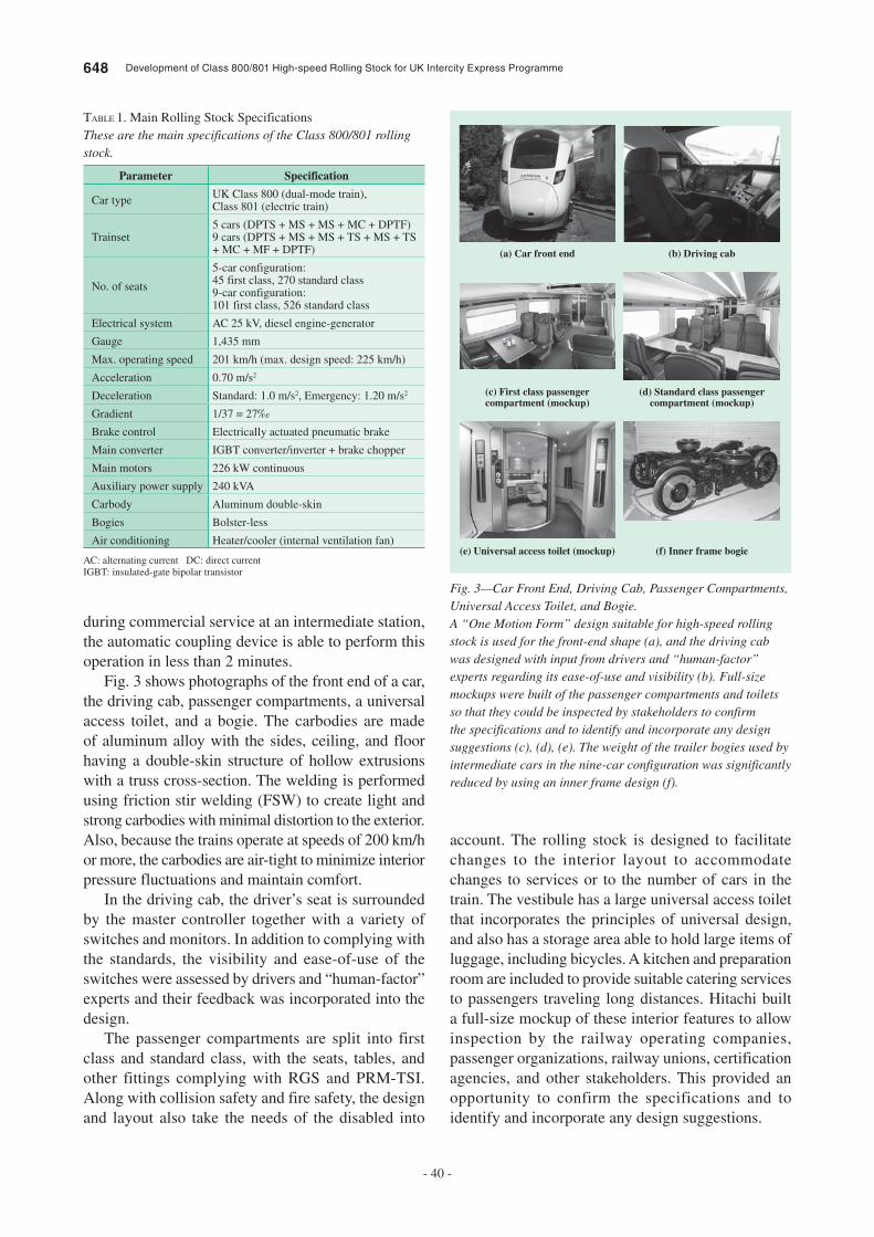
648 Development of Class 800/801 High-speed Rolling Stock for UK Intercity Express Programme
- 40 -
during commercial service at an intermediate station, the automatic coupling device is able to perform this operation in less than 2 minutes.
Fig. 3 shows photographs of the front end of a car, the driving cab, passenger compartments, a universal access toilet, and a bogie. The carbodies are made of aluminum alloy with the sides, ceiling, and floor having a double-skin structure of hollow extrusions with a truss cross-section. The welding is performed using friction stir welding (FSW) to create light and strong carbodies with minimal distortion to the exterior. Also, because the trains operate at speeds of 200 km/h or more, the carbodies are air-tight to minimize interior pressure fluctuations and maintain comfort.
In the driving cab, the driver’s seat is surrounded by the master controller together with a variety of switches and monitors. In addition to complying with the standards, the visibility and ease-of-use of the switches were assessed by drivers and “human-factor” experts and their feedback was incorporated into the design.
The passenger compartments are split into first class and standard class, with the seats, tables, and other fittings complying with RGS and PRM-TSI. Along with collision safety and fire safety, the design and layout also take the needs of the disabled into
account. The rolling stock is designed to facilitate changes to the interior layout to accommodate changes to services or to the number of cars in the train. The vestibule has a large universal access toilet that incorporates the principles of universal design, and also has a storage area able to hold large items of luggage, including bicycles. A kitchen and preparation room are included to provide suitable catering services to passengers traveling long distances. Hitachi built a full-size mockup of these interior features to allow inspection by the railway operating companies, passenger organizations, railway unions, certification agencies, and other stakeholders. This provided an opportunity to confirm the specifications and to identify and incorporate any design suggestions.
Parameter Specification
Car type UK Class 800 (dual-mode train), Class 801 (electric train)
Trainset5 cars (DPTS + MS + MS + MC + DPTF)9 cars (DPTS + MS + MS + TS + MS + TS + MC + MF + DPTF)
No. of seats
5-car configuration: 45 first class, 270 standard class9-car configuration: 101 first class, 526 standard class
Electrical system AC 25 kV, diesel engine-generator
Gauge 1,435 mm
Max. operating speed 201 km/h (max. design speed: 225 km/h)
Acceleration 0.70 m/s2
Deceleration Standard: 1.0 m/s2, Emergency: 1.20 m/s2
Gradient 1/37 = 27‰
Brake control Electrically actuated pneumatic brake
Main converter IGBT converter/inverter + brake chopper
Main motors 226 kW continuous
Auxiliary power supply 240 kVA
Carbody Aluminum double-skin
Bogies Bolster-less
Air conditioning Heater/cooler (internal ventilation fan)
TABLE 1. Main Rolling Stock SpecificationsThese are the main specifications of the Class 800/801 rolling stock.
AC: alternating current DC: direct current IGBT: insulated-gate bipolar transistor
(a) Car front end (b) Driving cab
(c) First class passengercompartment (mockup)
(d) Standard class passengercompartment (mockup)
(e) Universal access toilet (mockup) (f) Inner frame bogie
Fig. 3—Car Front End, Driving Cab, Passenger Compartments, Universal Access Toilet, and Bogie.A “One Motion Form” design suitable for high-speed rolling stock is used for the front-end shape (a), and the driving cab was designed with input from drivers and “human-factor” experts regarding its ease-of-use and visibility (b). Full-size mockups were built of the passenger compartments and toilets so that they could be inspected by stakeholders to confirm the specifications and to identify and incorporate any design suggestions (c), (d), (e). The weight of the trailer bogies used by intermediate cars in the nine-car configuration was significantly reduced by using an inner frame design (f).
Hitachi Review Vol. 63 (2014), No. 10 649
- 41 -
The bogies have a bolsterless configuration and are designed for stability and cornering performance as well as to minimize track damage and maintenance costs, with the structures of the motor and trailer bogies both made as light as possible. The weight of the trailer bogies used for intermediate cars on nine-car trains, in particular, was reduced significantly by using the inner frame structure shown in Fig. 3.
CLASS 800/801 ELECTRICAL SYSTEM
This section describes the features of the safety system, which consists of independent train protection systems: the Train Control and Management System (TCMS), which assists the work of the train crew; a data communication function that aids maintenance work; and a traction drive system that is powered by the overhead lines (catenaries) and GUs.
On-board Information System (TCMS)Fig. 4 shows a block diagram of the on-board information system on the Class 800/801, Fig. 5 shows a driving cab screen, and Fig. 6 shows examples of the display panels. The TCMS on the Class 800/801 uses the Ethernet-Autonomous Decentralized Train Integration System (E-ATI), an Ethernet-based communication system. E-ATI is a backbone communication system newly developed by Hitachi that provides improved reliability and redundancy by using fully independent dual routing. The system also complies with IEC 61375, and EN 50128 safety integrity level 2 (SIL2) requirements. The displays in the driving cab are designed with button locations, colors, and fonts that are chosen for their
ease of use and affinity with European Train Control System (ETCS) screens (described below). Similarly, the sizes, fonts, scrolling speeds, and information presented on the display panels are chosen to be easy for passengers to read. These also comply with TSI and RGS. The rolling stock is fitted with on-board servers that exchange data with wayside systems via third-generation (3G) and Wi-Fi*1 communications. The design also supports use of fourth-generation (4G) and WiMAX*2 communications as an option.
In addition to the above, an RGS-compliant integrated on-train data recorder (OTDR) and juridical recording unit (JRU), and an EN-compliant energy meter to record energy consumption and regeneration are fitted to the train.
OTDR(JRU)
SRS
Equipment Equipment Equipment
PIS+PACabdisplay
On-boardserver
3G/Wi-Fi (4G/WiMAX)
On-boardinformation system
E-ATI
Fig. 4—Block Diagram of On-board Information System.Reliability and redundancy have been improved by using fully independent dual routing based on Ethernet technology. The system is certified as satisfying SIL2.
SIL: safety integrity level Wi-Fi: Wireless Fidelity SRS: seat reservation system OTDR: on-train data recorder JRU: juridical recording unit E-ATI: Ethernet-Autonomous Train Integration System PIS: passenger information systems PA: public address
Fig. 5—Example Driving Cab Screen.The design uses button locations, colors, and fonts that are chosen for their ease of use and affinity with ETCS screens.
ETCS: European Train Control System
(a) Passenger compartment display panel
(b) External display panel(c) Seat reservation
display panel
Fig. 6—IEP Display Panels.The sizes, fonts, scrolling speeds, and information presented on the display panels are chosen to be easy for passengers to read (and are compliant with TSI and RGS standards).
TSI: Technical Specification for Interoperability RGS: Railway Group Standards
*1 Wi-Fi is a registered trademark of the Wi-Fi Alliance.*2 WiMAX is a trademark or registered trademark of the WiMAX Forum.
650 Development of Class 800/801 High-speed Rolling Stock for UK Intercity Express Programme
- 42 -
both have the same traction system and the rolling stock can be operated as either class by simply adding or removing GUs. On the Class 800, which is intended to run on both electrified and non-electrified track, each traction system has its own GU. On the other hand, the Class 801 is designed only for electrified lines and has one or two GUs depending on the length of the trainset (one GU for trainsets of five to nine cars, two GUs for trainsets of 10 to 12 cars). These GUs supply emergency traction power and auxiliary power in the event of a power outage on the catenary, and as an auxiliary power supply on non-electrified lines where the Class 801 is in service and pulled by a locomotive. This allows the Class 801 to operate on lines it would otherwise not be able to use and provides a backup in the event of a catenary power outage or other problem on the ground systems as well as non-electrified routes in loco-hauled mode.
To simplify the APS and make it easier to control, it draws power from the direct current (DC) stage of the traction system. Additionally, the on-board APSs operate in parallel to provide redundancy.
On-board Safety SystemsFig. 8 shows an overview of the safety systems, and Fig. 9 shows the driver machine interface (DMI) of the ETCS. The Class 800/801 is fitted with the Train Protection and Warning System (TPWS) as a legacy signaling system and Automatic Warning System (AWS) widely used on UK trains, and the British Rail-Automatic Train Protection (BR-ATP) system used between Paddington and Bristol on the GWML. It also has an ETCS (Level 2), which is planned to be introduced in the UK. The on-board ETCS was
The main functions of the TCMS on the Class 800/801 are described as follows.(1) Automatic train identification function
To simplify the rearrangement and management of train configurations, functions are provided for identifying the train (Class 800/801), for automatically determining the cars in the trainset and its total length, and for coupling and uncoupling up to 12 cars in normal and 24 cars in rescue or emergency mode.(2) Data communications
Communication with wayside systems is used to transmit rolling stock status information in realtime; to return the monitor data stored in the OTDR and other on-board devices to wayside systems in response to on-demand commands; and to receive daily schedules (timetables) and seat allocation data. It also provides easier maintenance by allowing the updating of public address announcements and the on-board system software.(3) Train control functions based on location
The train location is identified by using the global positioning system (GPS) and used for such functions as automatic control of internal and external display panels and systems for providing information to passengers [passenger information systems (PIS) and public address (PA)]; door interlock control [selective door operation (SDO) control] for stations where the platform is shorter than the train; seat reservation system (SRS) control for displaying seat allocations for each section of the route; and a driver advisory system (DAS) that instructs drivers how to optimize operation for minimum power consumption based on the timetable and the type of line they are travelling on. It is also used by the automatic function for selecting the correct power supply on the current section of track.(4) Passenger support function
The system counts the number of passengers on each car and can use public address announcements to inform passengers about which cars are less crowded, while also transmitting information about the passenger load to the wayside systems in real time.
Traction and APS SystemFig. 7 shows an overview of the traction and auxiliary power supply (APS) system. The system can select the appropriate power source from either the main transformer or the GUs. Also, the size and weight of the system were minimized by designing the power supply converter to be able to work with both power sources. To ensure that the Class 800 and 801 are able to adapt to future changes in operating practices, they
Supplyconverter
Generatorunit
Driveconverter
TM×4
AC400 V3Phase
DC110 V
APSwith BC
Fig. 7—Overview of Traction/APS System.The system provides both energy efficiency and operational flexibility, being able to draw power either from the catenary on electrified sections of track or from the engine-generator on non-electrified sections.
APS: auxiliary power supply BC: battery charger TM: traction motor

Hitachi Review Vol. 63 (2014), No. 10 651
- 43 -
system integration to allow for more sophisticated rolling stock control.(1) A function that includes selecting the correct on-board signaling devices for the ground side signaling system before and after the installation of ETCS. This is a fundamental function for operating the train safely on lines that have different ground side signaling systems (GWML and ECML).(2) A function includes sharing train information between the ETCS, TCMS, and Global System for Mobile Communications-Railway (GSM-R) (to simplify train data entry procedures for train crew and minimize errors).(3) On-board equipment control functions that use train location information and are implemented by the interoperation of TCMS and ETCS [the selection of power source (catenary or engine) is based on type of line, SDO, airtightness control, and vacuum circuit breaker (VCB) switching control for neutral sections].
DISTINCTIVE TECHNOLOGIES
These sections describe the GUs and the crashworthy structure, two distinctive technologies developed for the Class 800/801.
Engine-powered GeneratorsThis section describes the features of the GUs and peripheral systems on the Class 800/801.
Fig. 10 shows a GU and its main specifications. Since the GUs developed for the Class 800/801 are installed under the floor of the motor cars, the engine, generator, radiator, and other components are installed as a package to save space. The engines are designed with consideration for the environment, being fitted with a urea selective catalytic reduction (SCR) system, a technology for cleaning exhaust emissions, and complying with the Stage IIIB European Union (EU) exhaust emission standard. The engine cylinders have a V-configuration to minimize vibration and prevent any loss of comfort in the passenger compartments.
In addition to the GU, other components installed under the floor of drive cars include the traction converter, fuel tank, fire protection system, and brake system. An automatic fire-fighting system is installed to deal with fires in the top part of the engine. This system is designed to quickly extinguish any fire by using high-pressure nitrogen gas to spray it with water. Side-cowls are fitted to the sides of the GU to reduce external noise. The GU is attached to the body by vibration-isolating mountings and the
developed by Hitachi and underwent an EN012x series audit as part of the V-Train 3 project, receiving certification for compliance with SIL4 and the ETCS standard.
Along with the system integration of a number of different safety devices, the design and development of these safety systems implemented the following functions, with a particular focus on rolling stock
ETCS
Train informationDriver ID
Active/Suppress
Position andspeed information
On-board equipmentcontrol instructions, etc.
TPWS/AWS
BR-ATP
GWML only
TCMS
GSM-R(train radio)
On-boardequipment
(VCB, tractionsystem, etc.)
Fig. 8—Overview of On-board Safety Systems.The rolling stock is equipped with TPWS/AWS, which is used throughout the UK; BR-ATP, which is used on the GWML; and ETCS (developed in-house by Hitachi), which is to be deployed in the future. The system is designed to use the on-board safety functions that match the line being used and the wayside systems. Train information is also exchanged by TCMS and train radio (GSM-R).
BR-ATP: British Rail – Automatic Train Protection TCMS: train control and management system TPWS: train protection and warning system AWS: automatic warning system GSM-R: Global System for Mobile Communications-Railway VCB: vacuum circuit breaker ID: identification
Fig. 9—ETCS DMI.The interface complies with the ERTMS/ETCS and RGS standards.
DMI: driver machine interface ERTMS: European Rail Traffic Management System
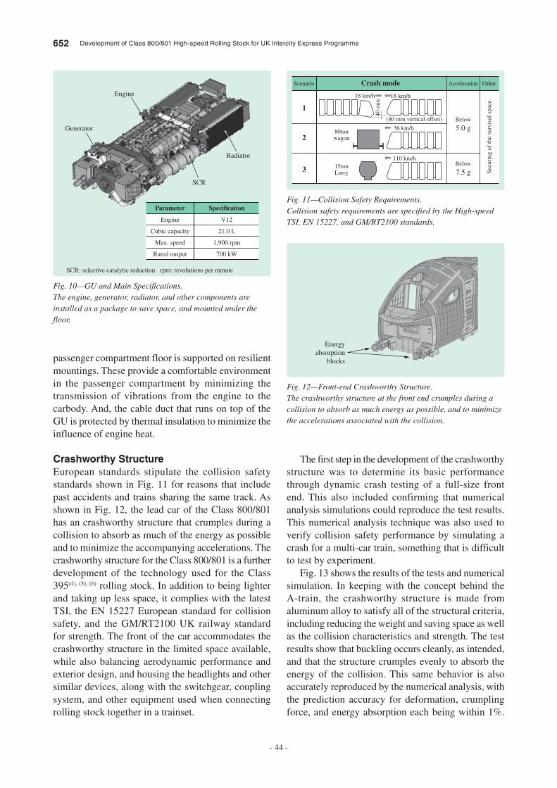
652 Development of Class 800/801 High-speed Rolling Stock for UK Intercity Express Programme
- 44 -
The first step in the development of the crashworthy structure was to determine its basic performance through dynamic crash testing of a full-size front end. This also included confirming that numerical analysis simulations could reproduce the test results. This numerical analysis technique was also used to verify collision safety performance by simulating a crash for a multi-car train, something that is difficult to test by experiment.
Fig. 13 shows the results of the tests and numerical simulation. In keeping with the concept behind the A-train, the crashworthy structure is made from aluminum alloy to satisfy all of the structural criteria, including reducing the weight and saving space as well as the collision characteristics and strength. The test results show that buckling occurs cleanly, as intended, and that the structure crumples evenly to absorb the energy of the collision. This same behavior is also accurately reproduced by the numerical analysis, with the prediction accuracy for deformation, crumpling force, and energy absorption each being within 1%.
passenger compartment floor is supported on resilient mountings. These provide a comfortable environment in the passenger compartment by minimizing the transmission of vibrations from the engine to the carbody. And, the cable duct that runs on top of the GU is protected by thermal insulation to minimize the influence of engine heat.
Crashworthy StructureEuropean standards stipulate the collision safety standards shown in Fig. 11 for reasons that include past accidents and trains sharing the same track. As shown in Fig. 12, the lead car of the Class 800/801 has an crashworthy structure that crumples during a collision to absorb as much of the energy as possible and to minimize the accompanying accelerations. The crashworthy structure for the Class 800/801 is a further development of the technology used for the Class 395(4), (5), (6) rolling stock. In addition to being lighter and taking up less space, it complies with the latest TSI, the EN 15227 European standard for collision safety, and the GM/RT2100 UK railway standard for strength. The front of the car accommodates the crashworthy structure in the limited space available, while also balancing aerodynamic performance and exterior design, and housing the headlights and other similar devices, along with the switchgear, coupling system, and other equipment used when connecting rolling stock together in a trainset.
Parameter Specification
Radiator
Engine
Generator
SCR
Engine V12
Cubic capacity 21.0 L
Max. speed 1,900 rpm
Rated output 700 kW
Fig. 10—GU and Main Specifications.The engine, generator, radiator, and other components are installed as a package to save space, and mounted under the floor.
SCR: selective catalytic reduction rpm: revolutions per minute
Scenario Acceleration Other
18 km/h 18 km/h
36 km/h
Below
5.0 g
Secu
ring
of
the
surv
ival
spa
ce
Below
7.5 g
80tonwagon
15tonLorry
110 km/h
(40 mm vertical offset)
40 m
m
Crash mode
1
2
3
Fig. 11—Collision Safety Requirements.Collision safety requirements are specified by the High-speed TSI, EN 15227, and GM/RT2100 standards.
Energyabsorption
blocks
Fig. 12—Front-end Crashworthy Structure.The crashworthy structure at the front end crumples during a collision to absorb as much energy as possible, and to minimize the accelerations associated with the collision.

Hitachi Review Vol. 63 (2014), No. 10 653
- 45 -
CONCLUSIONS
This article has given an overview of the Class 800/801 high-speed rolling stock for the UK IEP, and described the electrical system and distinctive technologies it employs.
Hitachi intends to continue developing more comfortable and attractive rolling stock that is compatible with European railway systems by combining existing technologies, developed in Japan for lighter weight and higher speed, with the advanced technologies developed for the Class 800/801, and to supply these together with maintenance services.
REFERENCES
(1) “Innovative Express – UK Intercity Express Programme,” Hitachi Hyoron, 95, 1, pp. 6–15 (Jan. 2013) in Japanese.
(2) M. Iwasaki et al., “Advanced Train Technology and New Development for Global Markets,” Hitachi Review 61, pp. 296–300 (Dec. 2012).
(3) T. Yamada, H. Ohba, “Latest A-Train Railcar Enhancements,” Hitachi Review 53, pp. 10–14 (Feb. 2004).
(4) T. Mochida et al., “Development and Maintenance of Class 395 High-speed Train for UK High Speed 1,” Hitachi Review 59, pp. 39–46 (Apr. 2010).
(5) K. Jordan et al., “Railway Business Strategy and R&D in Europe,” Hitachi Review 61, pp. 190–194 (Sep. 2012).
(6) T. Kawasaki, T. Yamaguchi, T. Mochida, “Railway-vehicle Technologies for European Railways,” Hitachi Review 57, pp. 61–65 (Mar. 2008).
This demonstrates that the predictions are comfortably within the requirement of the standard, which requires an error of 10% or less. Fig. 14 shows the results of a numerical analysis of a collision between multi-car trains. The results verify the design by showing that the integrity of the driving cab and passenger compartments (“survival spaces”) is retained without their collapsing, and that the deceleration is kept within the standard of 5G or less.
(a) Experimental testing (b) Simulation
Fig. 13—Results of Dynamic Crash Testing and Numerical Simulations.Dynamic crash testing of a full-size car front-end was used to determine the basic characteristics of the crashworthy structure. It was also confirmed that simulation (numerical analysis) could reproduce the experimental test results with sufficient accuracy.
Fig. 14—Numerical Analysis Simulating Collision between Multi-car Trains.The results verified the design by showing that the integrity of the driving cab and passenger compartments (“survival spaces”) is retained without their collapsing, and that the deceleration is kept within the standard of 5G or less.
654 Development of Class 800/801 High-speed Rolling Stock for UK Intercity Express Programme
- 46 -
Chris Robinson
Hitachi Rail Europe Ltd. He is currently engaged in the IEP project. Mr. Robinson is an incorporated engineer (IEng) and a member of The Institution of Engineering and Technology (IET) and Institution of Mechanical Engineers (IMechE).
Mitsuo Iwasaki
IEP Project, Kasado Works, Rail Systems Company, Hitachi, Ltd. He is currently engaged in coordinating the design of rolling stock for overseas markets.
Takahisa Yamamoto
IEP Project, Kasado Works, Rail Systems Company, Hitachi, Ltd. He is currently engaged in the design of rolling stock for Europe.
Toshihiko Mochida
IEP Project, Kasado Works, Rail Systems Company, Hitachi, Ltd. He is currently engaged in the design of rolling stock for Europe. Mr. Mochida holds a PE (USA) and is a member of The Japan Society of Mechanical Engineers.
Andrew Rogers
Hitachi Rail Europe Ltd. He is currently engaged in coordinating work on the IEP project. Mr. Rogers holds a BEng and Master of Business Administration (MBA).
Koji Agatsuma
Hitachi Rail Europe Ltd. He is currently engaged in work on rolling stock for projects outside Japan.
Satoru Inarida, Dr. Eng.
Process Designing Department, Mito Rail Systems Product Division, Rail systems Company, Hitachi, Ltd. He is currently engaged in coordinating work on on-board electrical systems, primarily for projects outside Japan. Dr. Inarida is a member of The Institute of Electrical Engineers of Japan (IEEJ) and IET.
Kenta Konishi
IEP Project, Kasado Works, Rail Systems Company, Hitachi, Ltd. He is currently engaged in the design of rolling stock for Europe.
ABOUT THE AUTHORS
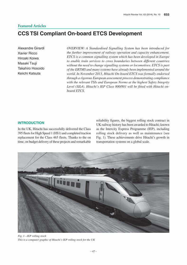
Hitachi Review Vol. 63 (2014), No. 10 655
- 47 -
Featured Articles
CCS TSI Compliant On-board ETCS Development
Alexandre Girardi
Xavier Ricco
Hiroaki Koiwa
Masaki Tsuji
Takahiro Hosoido
Keiichi Katsuta
OVERVIEW: A Standardised Signalling System has been introduced for the further improvement of railway operation and capacity enhancement. ETCS is a common signalling system which has been developed in Europe to enable train services to cross boundaries between different countries without the need to change signalling systems or locomotives. ETCS is part of the ERTMS and many systems have already been implemented around the world. In November 2013, Hitachi On-board ETCS was formally endorsed through a rigorous European assessment process demonstrating compliance with the relevant TSIs and European Norms at the highest Safety Integrity Level (SIL4). Hitachi’s IEP Class 800/801 will be fitted with Hitachi on-board ETCS.
INTRODUCTION
In the UK, Hitachi has successfully delivered the Class 395 fleets for High Speed 1 (HS1) and completed traction replacement for the Class 465 fleets. Thanks to the on time, on budget delivery of these projects and remarkable
reliability figures, the biggest rolling stock contract in UK railway history has been awarded to Hitachi; known as the Intercity Express Programme (IEP), including rolling stock delivery as well as maintenance (see Fig. 1). These achievements drive Hitachi’s growth in transportation systems on a global scale.
Fig. 1—IEP rolling stockThis is a computer graphic of Hitachi’s IEP rolling stock for the UK

656 CCS TSI Compliant On-board ETCS Development
- 48 -
Hitachi has commenced the development of an European Train Control System (ETCS) solution, which is a single and harmonised signalling system, with the ambition of becoming a global market supplier. This has been a joint development with Network Rail (NR) who is the Infrastructure Manager of the UK rail network and responsible for the implementation of ETCS in accordance with applicable EU directives. Hitachi, working in collaboration with NR, successfully delivered a proof of concept for the on-board Hitachi ETCS. This was fitted to a Class 97 locomotive as part of the Verification Train 3 project. This tested interoperability with a different supplier’s trackside system that is currently in use on the Cambrian Line.
GENERAL DESCRIPTION OF ETCS
Deployment
ETCS is a common signalling system which has been developed throughout Europe, led by the European Union to enable an interoperable train service. It is now being embraced by a growing number of other countries worldwide, especially in non-EU countries such as China and India. More than 9,000 trains and 68,000 km of track have now been fitted with ETCS.
System Architecture Description
Fig. 2 shows the generic ETCS system architecture. Eurobalises are installed between running rails to provide geographical location information to ETCS fitted trains. For the most basic implementation (known as Level 1) trackside Lineside Electronic Units (LEUs) generate Movement Authorities (MAs) based on signal aspects. These are then transmitted to the trainborne controller via Eurobalises. For the next step ‘Level 2’ implementation (to be introduced in the UK) an Radio Block Centre (RBC) is responsible for generating the MA and sending it to the train via the Global System for Mobile Communication - Railway (GSM-R) network, giving a continuous communication train control system. For both cases, train detection is managed by a trackside subsystem such as track circuits.
The main on-board unit is called an European Vital Computer (EVC) which supervises the train, generating a braking curve based on information such as the MA, train speed and current position. This braking curve is calculated to protect the train from overspeeding and exceeding the limit of the given movement authority. The EVC has a major responsibility for safety critical functions. Information
including the current speed, distance to end of MA and the track condition is displayed on the Driver Machine Interface (DMI). The DMI is also used for entering driver identification and train running number. Train information and behaviour is stored in a train recorder known as the Juridical Recording Unit (JRU). This is mandatory by law for the detailed investigation of root causes of incidents, therefore, the JRU has been designed for water resistance, fire resistance and crashworthiness.
ON-BOARD ETCS DEVELOPMENT
Key technical challenges
The following are the key technical challenges for on-board ETCS development:• Development of a robust platform applicable for the
variety of ETCS functions• Compliance with mandatory European Standards
On-board ETCS
Trackside ETCS
TIU
BTM
JRU
RTM
GSM-R
Eurobalise
LEU
Interlocking
RBC
DMI
EVC
Fig. 2—ETCS and Its InterfaceThis shows an overall ETCS architecture and its interface defined in EU directives.
TIU: train interface unit, DMI: driver machine interface, JRU: juridical recording unit, BTM: balise transmission module, EVC: european vital computer, RTM: radio transmission module, GSM-R: Global System for Mobile Communications-Railway, RBC: radio block centre, LEU: lineside electronic unit
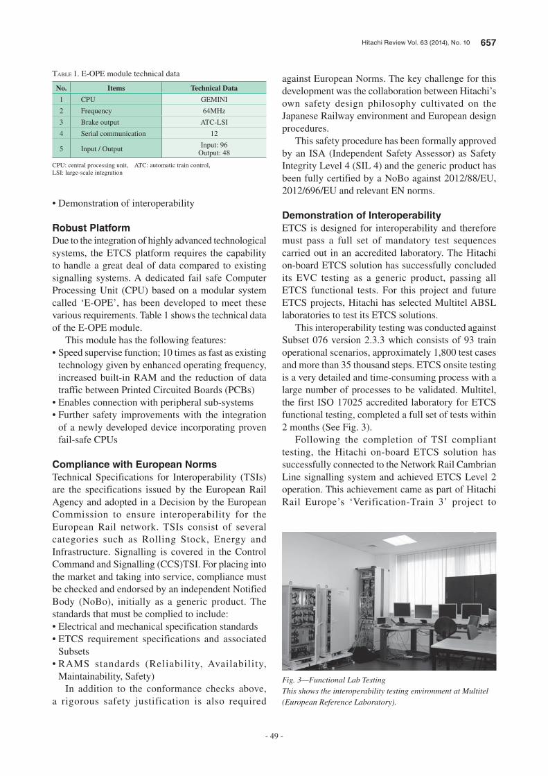
Hitachi Review Vol. 63 (2014), No. 10 657
- 49 -
• Demonstration of interoperability
Robust Platform
Due to the integration of highly advanced technological systems, the ETCS platform requires the capability to handle a great deal of data compared to existing signalling systems. A dedicated fail safe Computer Processing Unit (CPU) based on a modular system called ‘E-OPE’, has been developed to meet these various requirements. Table 1 shows the technical data of the E-OPE module.
This module has the following features:• Speed supervise function; 10 times as fast as existing
technology given by enhanced operating frequency, increased built-in RAM and the reduction of data traffic between Printed Circuited Boards (PCBs)
• Enables connection with peripheral sub-systems• Further safety improvements with the integration
of a newly developed device incorporating proven fail-safe CPUs
Compliance with European Norms
Technical Specifications for Interoperability (TSIs) are the specifications issued by the European Rail Agency and adopted in a Decision by the European Commission to ensure interoperability for the European Rail network. TSIs consist of several categories such as Rolling Stock, Energy and Infrastructure. Signalling is covered in the Control Command and Signalling (CCS)TSI. For placing into the market and taking into service, compliance must be checked and endorsed by an independent Notified Body (NoBo), initially as a generic product. The standards that must be complied to include:• Electrical and mechanical specification standards• ETCS requirement specifications and associated
Subsets• RAMS standards (Reliability, Availability,
Maintainability, Safety)In addition to the conformance checks above,
a rigorous safety justification is also required
against European Norms. The key challenge for this development was the collaboration between Hitachi’s own safety design philosophy cultivated on the Japanese Railway environment and European design procedures.
This safety procedure has been formally approved by an ISA (Independent Safety Assessor) as Safety Integrity Level 4 (SIL 4) and the generic product has been fully certified by a NoBo against 2012/88/EU, 2012/696/EU and relevant EN norms.
Demonstration of Interoperability
ETCS is designed for interoperability and therefore must pass a full set of mandatory test sequences carried out in an accredited laboratory. The Hitachi on-board ETCS solution has successfully concluded its EVC testing as a generic product, passing all ETCS functional tests. For this project and future ETCS projects, Hitachi has selected Multitel ABSL laboratories to test its ETCS solutions.
This interoperability testing was conducted against Subset 076 version 2.3.3 which consists of 93 train operational scenarios, approximately 1,800 test cases and more than 35 thousand steps. ETCS onsite testing is a very detailed and time-consuming process with a large number of processes to be validated. Multitel, the first ISO 17025 accredited laboratory for ETCS functional testing, completed a full set of tests within 2 months (See Fig. 3).
Following the completion of TSI compliant testing, the Hitachi on-board ETCS solution has successfully connected to the Network Rail Cambrian Line signalling system and achieved ETCS Level 2 operation. This achievement came as part of Hitachi Rail Europe’s ‘Verification-Train 3’ project to
TABLE 1. E-OPE module technical data
No. Items Technical Data
1 CPU GEMINI
2 Frequency 64MHz
3 Brake output ATC-LSI
4 Serial communication 12
5 Input / Output Input: 96Output: 48
CPU: central processing unit, ATC: automatic train control, LSI: large-scale integration
Fig. 3—Functional Lab TestingThis shows the interoperability testing environment at Multitel (European Reference Laboratory).
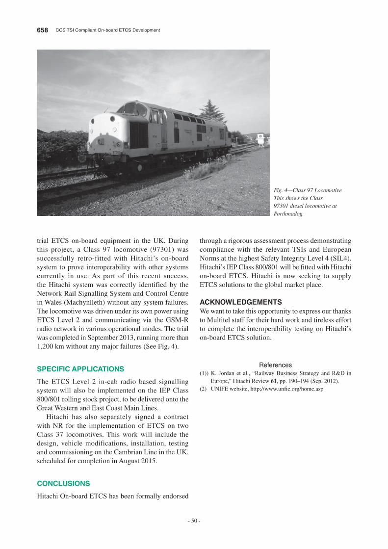
658 CCS TSI Compliant On-board ETCS Development
- 50 -
trial ETCS on-board equipment in the UK. During this project, a Class 97 locomotive (97301) was successfully retro-fitted with Hitachi’s on-board system to prove interoperability with other systems currently in use. As part of this recent success, the Hitachi system was correctly identified by the Network Rail Signalling System and Control Centre in Wales (Machynlleth) without any system failures. The locomotive was driven under its own power using ETCS Level 2 and communicating via the GSM-R radio network in various operational modes. The trial was completed in September 2013, running more than 1,200 km without any major failures (See Fig. 4).
SPECIFIC APPLICATIONS
The ETCS Level 2 in-cab radio based signalling system will also be implemented on the IEP Class 800/801 rolling stock project, to be delivered onto the Great Western and East Coast Main Lines.
Hitachi has also separately signed a contract with NR for the implementation of ETCS on two Class 37 locomotives. This work will include the design, vehicle modifications, installation, testing and commissioning on the Cambrian Line in the UK, scheduled for completion in August 2015.
CONCLUSIONS
Hitachi On-board ETCS has been formally endorsed
through a rigorous assessment process demonstrating compliance with the relevant TSIs and European Norms at the highest Safety Integrity Level 4 (SIL4). Hitachi’s IEP Class 800/801 will be fitted with Hitachi on-board ETCS. Hitachi is now seeking to supply ETCS solutions to the global market place.
ACKNOWLEDGEMENTS
We want to take this opportunity to express our thanks to Multitel staff for their hard work and tireless effort to complete the interoperability testing on Hitachi’s on-board ETCS solution.
References
(1)) K. Jordan et al., “Railway Business Strategy and R&D in Europe,” Hitachi Review 61, pp. 190–194 (Sep. 2012).
(2) UNIFE website, http;//www.unfie.org/home.asp
Fig. 4—Class 97 LocomotiveThis shows the Class 97301 diesel locomotive at Porthmadog.

Hitachi Review Vol. 63 (2014), No. 10 659
- 51 -
Xavier Ricco
Received his master grade in Information Science from the University of Valenciennes in France in 2002. He worked for Multitel in the department of Human Machine Interface since 2001 on a number of Framework Programme European Projects. Since 2007, he joined the Railway Certification Department as ERTMS group leader responsible to achieve ETCS equipment test.
Masaki Tsuji
Joined Hitachi in 1999 , and now works at Hitachi Rail Systems Company, Mito Transportation System Division, Japan, as Senior Signalling Engineer. He is currently engaged in ETCS retrofit project in the UK.
Keiichi Katsuta, MIET
Joined Hitachi in 2001, and now works at Hitachi Research Laboratory, as a Senior Researcher. He is in charge of R&D for the next generation of ATP systems, and takes a support role for the international standards.
Alexandre Girardi, PhD
Joined Multitel ASBL in 2004 and is now Head of the Railway Certification Department and adjunct of the Head of the Human Machine Interface Department, he also manages a number of R&D groups inside the Railway Certification Dept. including ETCS laboratories, as well as a number of TEN-T (Trans European Network – EU 60009-S) and INEA (Innovation & Networks Executive Agency – EU 60018-P) projects on ERTMS for the European Commission as coordinator.
Hiroaki Koiwa, MIRSE
Joined Hitachi in 2001 and Hitachi Rail Europe in 2006 as a Project Manager for the Signalling & Train Control business; he is now Head of Signalling Engineering for the European Rail Business.
Takahiro Hosoido
Joined Hitachi in 2002, and now works at Hitachi Rail Systems Company, Mito Transportatoin System Division, Japan, as Senior Signalling Engineer. He is responsible for IEP signalling system integration.
ABOUT THE AUTHORS
660 Hitachi Review Vol. 63 (2014), No. 10
- 52 -
Featured Articles
New Portable Radio Terminal for ATOS—Development Based on Experience Design—
Yohei Umehara
Takumi Inokuchi
Satomi Hori
Naoyuki Kanazawa
Noriya Ishii
Rika Kambara
OVERVIEW: The railways that form part of the transportation infrastructure of the Tokyo region operate with very high traffic densities, unmatched by anywhere else in the world. The traffic management system used on these Tokyo region railways handles not only railway operations, but also other functions such as enhancing services to passengers and improving safety for the maintenance workers responsible for maintenance and inspection of railway equipment. The lines controlled and functions performed by the traffic management system for the Tokyo region have been progressively expanded to the extent that the system now covers most lines in the region. However, because the architecture it is based on is now about 18 years old, support and maintenance of the overall system are becoming increasingly difficult. Accordingly, along with resolving problems that apply to the entire system, experience design has been utilized to undertake a major upgrade of the “portable radio terminal” used by maintenance workers with the aims of overcoming system aging and eliminating reliance on fixed-wire and wireless communications.
INTRODUCTION
RAILWAY services in the Tokyo region operate with very high traffic densities, unmatched by anywhere else in the world. The Autonomous decentralized Transport Operation control System (ATOS) that manages these services is a large autonomous and decentralized system that was installed to improve traffic management productivity, enhance services to passengers by providing realtime schedule information, and improve the safety of maintenance work. Having been expanded to cover 20 lines with an approximate total length of 1,270 km since it was first installed in 1996, the system is a vital part of the social infrastructure and is critical to the safe and reliable operation of transportation services (see Fig. 1).
Maintenance work on a railway covers such tasks as replacing parts and performing inspections of the equipment associated with the railway lines, signals, and other systems. Maintenance workers use information terminals and the “portable radio terminal” to perform their routine maintenance work. The information terminals are personal computers (PCs) installed at the maintenance center. They are
used to download data to the “portable radio terminals” and to view information such as operating status and train schedules. The “portable radio terminal” is a small handheld device that can be taken to jobs and used to issue control requests such as “railway track closing” to prevent trains from entering a section of track being worked on, or to test signal equipment. Given the very high traffic density on Tokyo railways, the information terminals and the “portable radio terminal” are important systems for improving the productivity of maintenance work and the safety of maintenance workers.
With ATOS having been in service for approximately 18 years, this equipment is now aging, these maintenance support devices included. Furthermore, configuring the equipment has become progressively more complex and difficult to maintain as the system has been rolled out to new lines and its functions upgraded. Accordingly, a system-wide upgrade was undertaken based on the following requirements.(1) Provide a network environment suitable for service expansion.(2) Optimize the equipment configuration to enhance maintenance productivity.
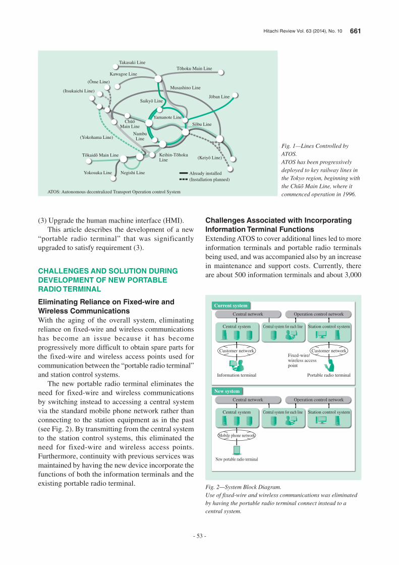
Hitachi Review Vol. 63 (2014), No. 10 661
- 53 -
(3) Upgrade the human machine interface (HMI).This article describes the development of a new
“portable radio terminal” that was significantly upgraded to satisfy requirement (3).
CHALLENGES AND SOLUTION DURING DEVELOPMENT OF NEW PORTABLE RADIO TERMINAL
Eliminating Reliance on Fixed-wire and Wireless CommunicationsWith the aging of the overall system, eliminating reliance on fixed-wire and wireless communications has become an issue because it has become progressively more difficult to obtain spare parts for the fixed-wire and wireless access points used for communication between the “portable radio terminal” and station control systems.
The new portable radio terminal eliminates the need for fixed-wire and wireless communications by switching instead to accessing a central system via the standard mobile phone network rather than connecting to the station equipment as in the past (see Fig. 2). By transmitting from the central system to the station control systems, this eliminated the need for fixed-wire and wireless access points. Furthermore, continuity with previous services was maintained by having the new device incorporate the functions of both the information terminals and the existing portable radio terminal.
Challenges Associated with Incorporating Information Terminal FunctionsExtending ATOS to cover additional lines led to more information terminals and portable radio terminals being used, and was accompanied also by an increase in maintenance and support costs. Currently, there are about 500 information terminals and about 3,000
Negishi LineYokosuka Line
(Yokohama Line)
(Itsukaichi Line)
Kawagoe Line
Takasaki Line
Musashino Line
Already installed(Installation planned)
Yamanote Line
NambuLine
ATOS: Autonomous decentralized Transport Operation control System
Fig. 1—Lines Controlled by ATOS.ATOS has been progressively deployed to key railway lines in the Tokyo region, beginning with the Ch Main Line, where it commenced operation in 1996.
Customer network
Central system
Customer network
Station control system
Information terminal Portable radio terminal
Fixed-wire/wireless access point
Central system for each line
Central network
Current system
Operation control network
Mobile phone network
Central system Station control system
New portable radio terminal
Central system for each line
Central network
New system
Operation control network
Fig. 2—System Block Diagram.Use of fixed-wire and wireless communications was eliminated by having the portable radio terminal connect instead to a central system.
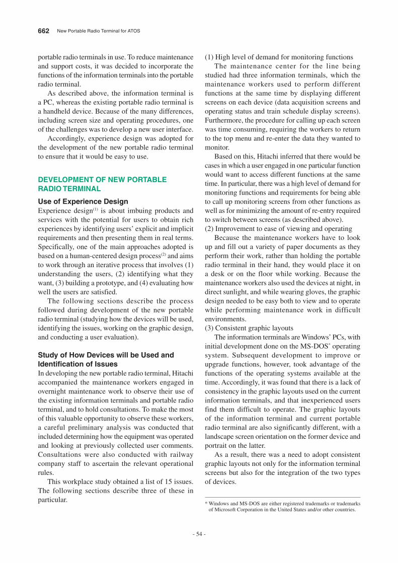
662 New Portable Radio Terminal for ATOS
- 54 -
portable radio terminals in use. To reduce maintenance and support costs, it was decided to incorporate the functions of the information terminals into the portable radio terminal.
As described above, the information terminal is a PC, whereas the existing portable radio terminal is a handheld device. Because of the many differences, including screen size and operating procedures, one of the challenges was to develop a new user interface.
Accordingly, experience design was adopted for the development of the new portable radio terminal to ensure that it would be easy to use.
DEVELOPMENT OF NEW PORTABLE RADIO TERMINAL
Use of Experience DesignExperience design(1) is about imbuing products and services with the potential for users to obtain rich experiences by identifying users’ explicit and implicit requirements and then presenting them in real terms. Specifically, one of the main approaches adopted is based on a human-centered design process(2) and aims to work through an iterative process that involves (1) understanding the users, (2) identifying what they want, (3) building a prototype, and (4) evaluating how well the users are satisfied.
The following sections describe the process followed during development of the new portable radio terminal (studying how the devices will be used, identifying the issues, working on the graphic design, and conducting a user evaluation).
Study of How Devices will be Used and Identifi cation of IssuesIn developing the new portable radio terminal, Hitachi accompanied the maintenance workers engaged in overnight maintenance work to observe their use of the existing information terminals and portable radio terminal, and to hold consultations. To make the most of this valuable opportunity to observe these workers, a careful preliminary analysis was conducted that included determining how the equipment was operated and looking at previously collected user comments. Consultations were also conducted with railway company staff to ascertain the relevant operational rules.
This workplace study obtained a list of 15 issues. The following sections describe three of these in particular.
(1) High level of demand for monitoring functionsThe maintenance center for the line being
studied had three information terminals, which the maintenance workers used to perform different functions at the same time by displaying different screens on each device (data acquisition screens and operating status and train schedule display screens). Furthermore, the procedure for calling up each screen was time consuming, requiring the workers to return to the top menu and re-enter the data they wanted to monitor.
Based on this, Hitachi inferred that there would be cases in which a user engaged in one particular function would want to access different functions at the same time. In particular, there was a high level of demand for monitoring functions and requirements for being able to call up monitoring screens from other functions as well as for minimizing the amount of re-entry required to switch between screens (as described above).(2) Improvement to ease of viewing and operating
Because the maintenance workers have to look up and fill out a variety of paper documents as they perform their work, rather than holding the portable radio terminal in their hand, they would place it on a desk or on the floor while working. Because the maintenance workers also used the devices at night, in direct sunlight, and while wearing gloves, the graphic design needed to be easy both to view and to operate while performing maintenance work in difficult environments.(3) Consistent graphic layouts
The information terminals are Windows* PCs, with initial development done on the MS-DOS* operating system. Subsequent development to improve or upgrade functions, however, took advantage of the functions of the operating systems available at the time. Accordingly, it was found that there is a lack of consistency in the graphic layouts used on the current information terminals, and that inexperienced users find them difficult to operate. The graphic layouts of the information terminal and current portable radio terminal are also significantly different, with a landscape screen orientation on the former device and portrait on the latter.
As a result, there was a need to adopt consistent graphic layouts not only for the information terminal screens but also for the integration of the two types of devices.
* Windows and MS-DOS are either registered trademarks or trademarks of Microsoft Corporation in the United States and/or other countries.
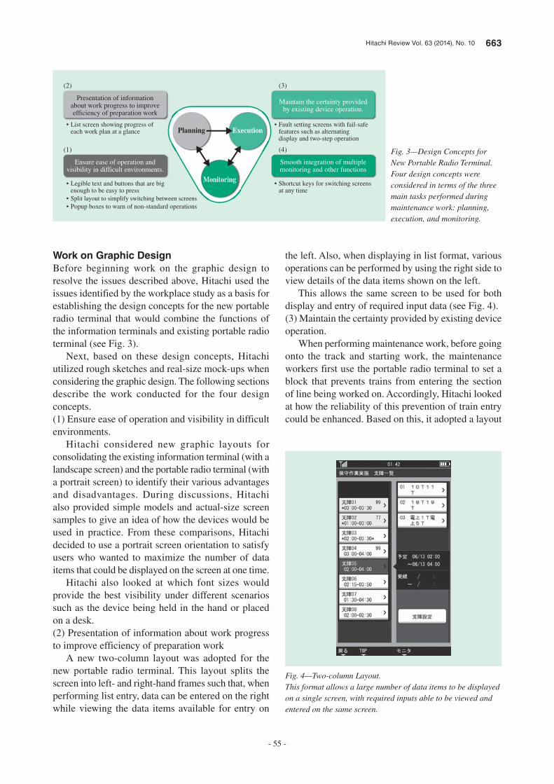
Hitachi Review Vol. 63 (2014), No. 10 663
- 55 -
Work on Graphic DesignBefore beginning work on the graphic design to resolve the issues described above, Hitachi used the issues identified by the workplace study as a basis for establishing the design concepts for the new portable radio terminal that would combine the functions of the information terminals and existing portable radio terminal (see Fig. 3).
Next, based on these design concepts, Hitachi utilized rough sketches and real-size mock-ups when considering the graphic design. The following sections describe the work conducted for the four design concepts.(1) Ensure ease of operation and visibility in difficult environments.
Hitachi considered new graphic layouts for consolidating the existing information terminal (with a landscape screen) and the portable radio terminal (with a portrait screen) to identify their various advantages and disadvantages. During discussions, Hitachi also provided simple models and actual-size screen samples to give an idea of how the devices would be used in practice. From these comparisons, Hitachi decided to use a portrait screen orientation to satisfy users who wanted to maximize the number of data items that could be displayed on the screen at one time.
Hitachi also looked at which font sizes would provide the best visibility under different scenarios such as the device being held in the hand or placed on a desk.(2) Presentation of information about work progress to improve efficiency of preparation work
A new two-column layout was adopted for the new portable radio terminal. This layout splits the screen into left- and right-hand frames such that, when performing list entry, data can be entered on the right while viewing the data items available for entry on
the left. Also, when displaying in list format, various operations can be performed by using the right side to view details of the data items shown on the left.
This allows the same screen to be used for both display and entry of required input data (see Fig. 4).(3) Maintain the certainty provided by existing device operation.
When performing maintenance work, before going onto the track and starting work, the maintenance workers first use the portable radio terminal to set a block that prevents trains from entering the section of line being worked on. Accordingly, Hitachi looked at how the reliability of this prevention of train entry could be enhanced. Based on this, it adopted a layout
Monitoring
Planning Execution
(2)
Presentation of informationabout work progress to improveefficiency of preparation work
(1)
Ensure ease of operation andvisibility in difficult environments.
• List screen showing progress of each work plan at a glance
• Legible text and buttons that are big enough to be easy to press
• Split layout to simplify switching between screens• Popup boxes to warn of non-standard operations
(3)
Maintain the certainty providedby existing device operation.
(4)
Smooth integration of multiplemonitoring and other functions
• Fault setting screens with fail-safe features such as alternating display and two-step operation
• Shortcut keys for switching screens at any time
Fig. 3—Design Concepts for New Portable Radio Terminal.Four design concepts were considered in terms of the three main tasks performed during maintenance work: planning, execution, and monitoring.
Fig. 4—Two-column Layout.This format allows a large number of data items to be displayed on a single screen, with required inputs able to be viewed and entered on the same screen.
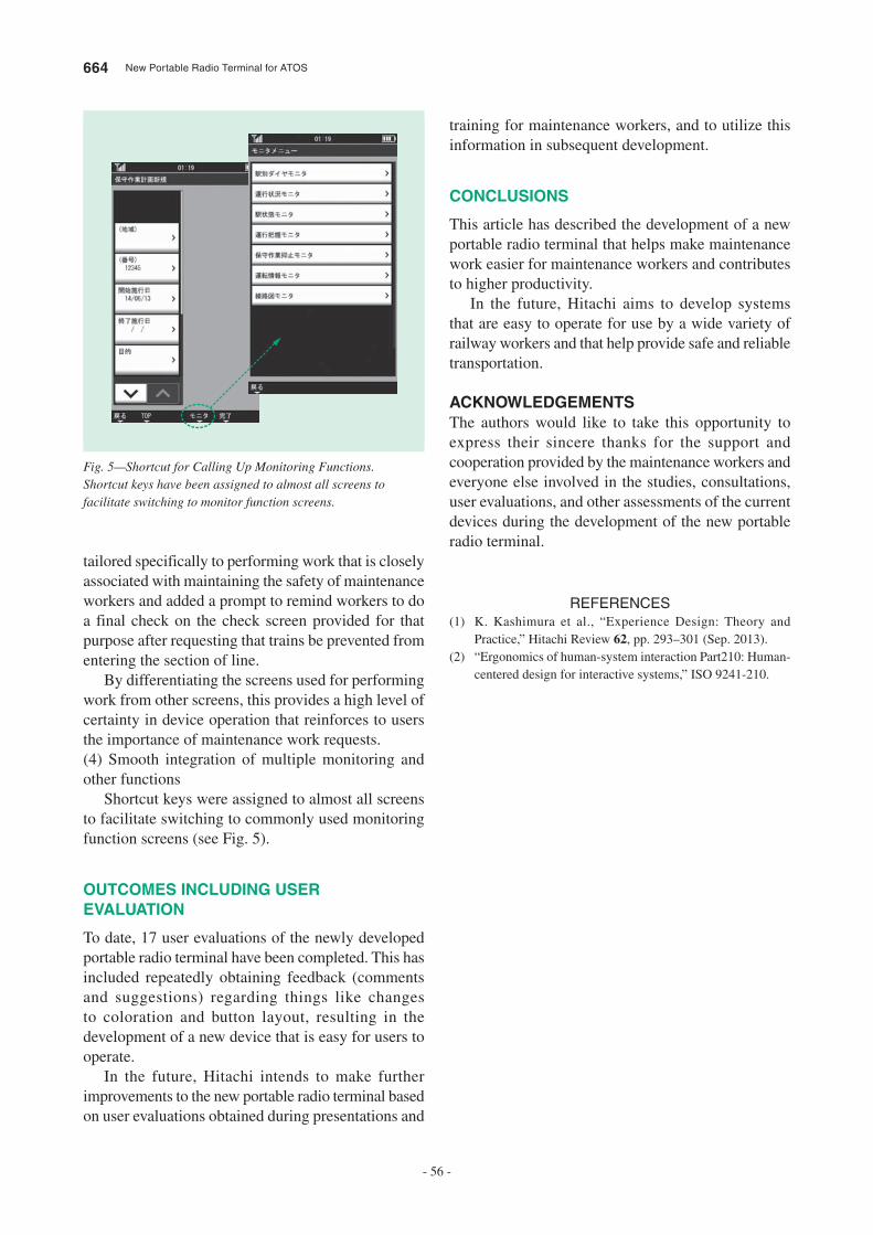
664 New Portable Radio Terminal for ATOS
- 56 -
training for maintenance workers, and to utilize this information in subsequent development.
CONCLUSIONS
This article has described the development of a new portable radio terminal that helps make maintenance work easier for maintenance workers and contributes to higher productivity.
In the future, Hitachi aims to develop systems that are easy to operate for use by a wide variety of railway workers and that help provide safe and reliable transportation.
ACKNOWLEDGEMENTSThe authors would like to take this opportunity to express their sincere thanks for the support and cooperation provided by the maintenance workers and everyone else involved in the studies, consultations, user evaluations, and other assessments of the current devices during the development of the new portable radio terminal.
REFERENCES
(1) K. Kashimura et al., “Experience Design: Theory and Practice,” Hitachi Review 62, pp. 293–301 (Sep. 2013).
(2) “Ergonomics of human-system interaction Part210: Human-centered design for interactive systems,” ISO 9241-210.
tailored specifically to performing work that is closely associated with maintaining the safety of maintenance workers and added a prompt to remind workers to do a final check on the check screen provided for that purpose after requesting that trains be prevented from entering the section of line.
By differentiating the screens used for performing work from other screens, this provides a high level of certainty in device operation that reinforces to users the importance of maintenance work requests.(4) Smooth integration of multiple monitoring and other functions
Shortcut keys were assigned to almost all screens to facilitate switching to commonly used monitoring function screens (see Fig. 5).
OUTCOMES INCLUDING USER EVALUATION
To date, 17 user evaluations of the newly developed portable radio terminal have been completed. This has included repeatedly obtaining feedback (comments and suggestions) regarding things like changes to coloration and button layout, resulting in the development of a new device that is easy for users to operate.
In the future, Hitachi intends to make further improvements to the new portable radio terminal based on user evaluations obtained during presentations and
Fig. 5—Shortcut for Calling Up Monitoring Functions.Shortcut keys have been assigned to almost all screens to facilitate switching to monitor function screens.
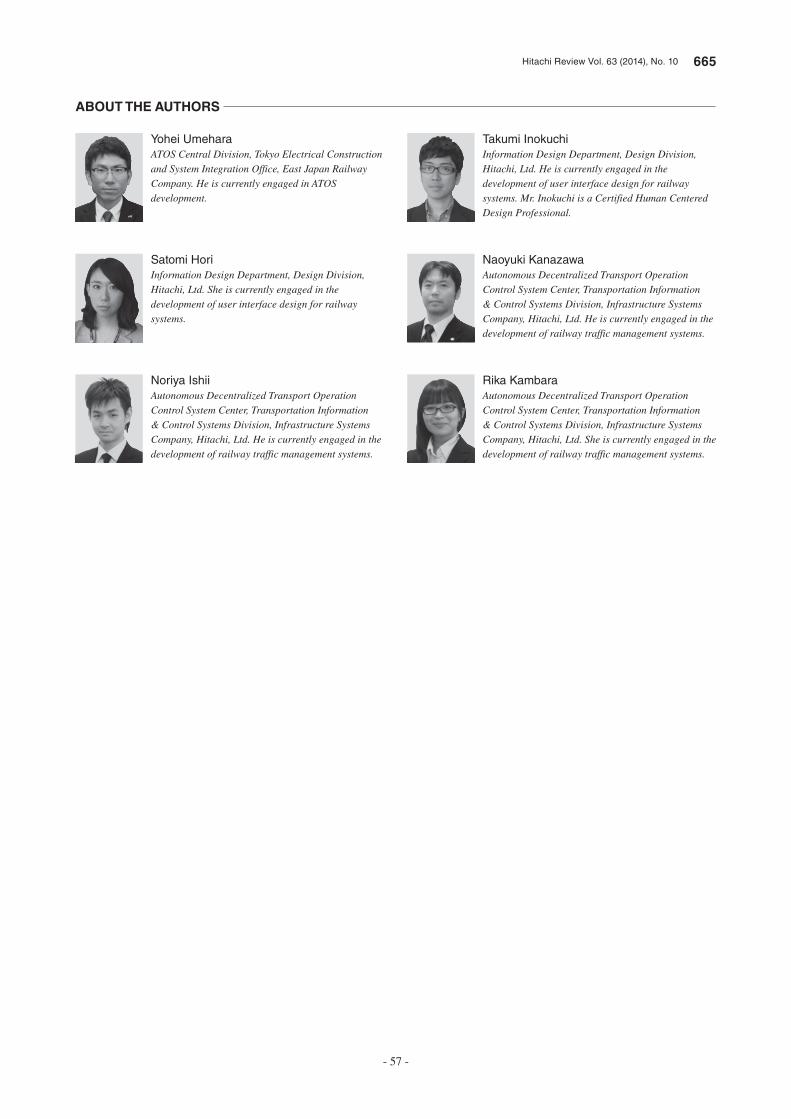
Hitachi Review Vol. 63 (2014), No. 10 665
- 57 -
Takumi Inokuchi
Information Design Department, Design Division, Hitachi, Ltd. He is currently engaged in the development of user interface design for railway systems. Mr. Inokuchi is a Certified Human Centered Design Professional.
Naoyuki Kanazawa
Autonomous Decentralized Transport Operation Control System Center, Transportation Information & Control Systems Division, Infrastructure Systems Company, Hitachi, Ltd. He is currently engaged in the development of railway traffic management systems.
Rika Kambara
Autonomous Decentralized Transport Operation Control System Center, Transportation Information & Control Systems Division, Infrastructure Systems Company, Hitachi, Ltd. She is currently engaged in the development of railway traffic management systems.
Yohei Umehara
ATOS Central Division, Tokyo Electrical Construction and System Integration Office, East Japan Railway Company. He is currently engaged in ATOS development.
Satomi Hori
Information Design Department, Design Division, Hitachi, Ltd. She is currently engaged in the development of user interface design for railway systems.
Noriya Ishii
Autonomous Decentralized Transport Operation Control System Center, Transportation Information & Control Systems Division, Infrastructure Systems Company, Hitachi, Ltd. He is currently engaged in the development of railway traffic management systems.
ABOUT THE AUTHORS
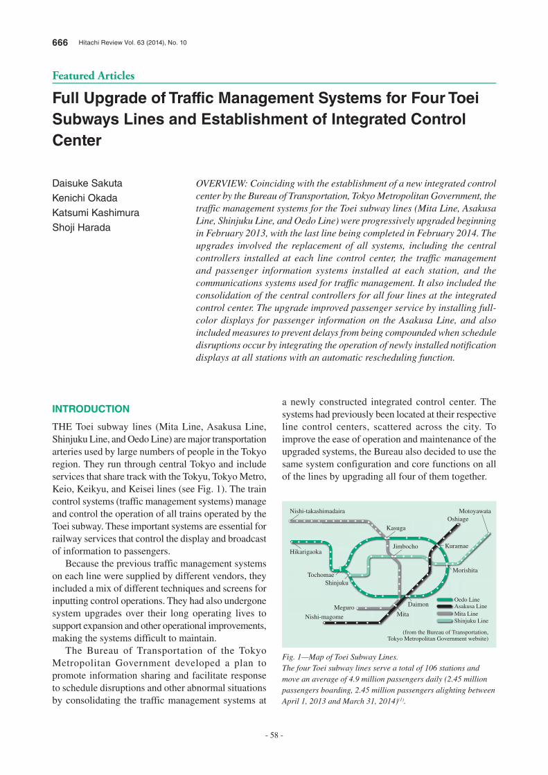
666 Hitachi Review Vol. 63 (2014), No. 10
- 58 -
Featured Articles
Full Upgrade of Traffic Management Systems for Four Toei
Subways Lines and Establishment of Integrated Control
Center
Daisuke Sakuta
Kenichi Okada
Katsumi Kashimura
Shoji Harada
OVERVIEW: Coinciding with the establishment of a new integrated control center by the Bureau of Transportation, Tokyo Metropolitan Government, the traffic management systems for the Toei subway lines (Mita Line, Asakusa Line, Shinjuku Line, and Oedo Line) were progressively upgraded beginning in February 2013, with the last line being completed in February 2014. The upgrades involved the replacement of all systems, including the central controllers installed at each line control center, the traffic management and passenger information systems installed at each station, and the communications systems used for traffic management. It also included the consolidation of the central controllers for all four lines at the integrated control center. The upgrade improved passenger service by installing full-color displays for passenger information on the Asakusa Line, and also included measures to prevent delays from being compounded when schedule disruptions occur by integrating the operation of newly installed notification displays at all stations with an automatic rescheduling function.
INTRODUCTION
THE Toei subway lines (Mita Line, Asakusa Line, Shinjuku Line, and Oedo Line) are major transportation arteries used by large numbers of people in the Tokyo region. They run through central Tokyo and include services that share track with the Tokyu, Tokyo Metro, Keio, Keikyu, and Keisei lines (see Fig. 1). The train control systems (traffic management systems) manage and control the operation of all trains operated by the Toei subway. These important systems are essential for railway services that control the display and broadcast of information to passengers.
Because the previous traffic management systems on each line were supplied by different vendors, they included a mix of different techniques and screens for inputting control operations. They had also undergone system upgrades over their long operating lives to support expansion and other operational improvements, making the systems difficult to maintain.
The Bureau of Transportation of the Tokyo Metropolitan Government developed a plan to promote information sharing and facilitate response to schedule disruptions and other abnormal situations by consolidating the traffic management systems at
a newly constructed integrated control center. The systems had previously been located at their respective line control centers, scattered across the city. To improve the ease of operation and maintenance of the upgraded systems, the Bureau also decided to use the same system configuration and core functions on all of the lines by upgrading all four of them together.
Oedo Line
Nishi-takashimadaira
Hikarigaoka
TochomaeShinjuku
Asakusa LineMita LineShinjuku Line
(from the Bureau of Transportation, Tokyo Metropolitan Government website)
Kasuga
Oshiage
Kuramae
Morishita
Daimon
Motoyawata
MitaMeguro
Nishi-magome
Jimbocho
Fig. 1—Map of Toei Subway Lines.The four Toei subway lines serve a total of 106 stations and move an average of 4.9 million passengers daily (2.45 million passengers boarding, 2.45 million passengers alighting between April 1, 2013 and March 31, 2014)(1).
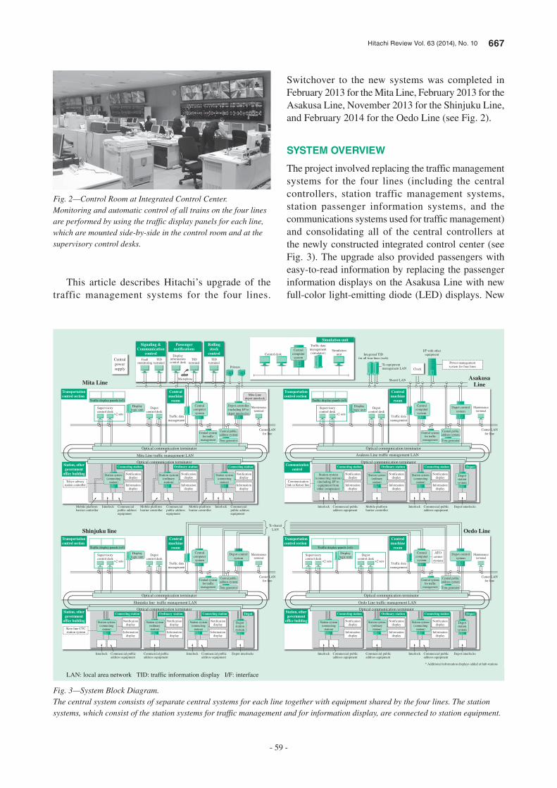
Hitachi Review Vol. 63 (2014), No. 10 667
- 59 -
This article describes Hitachi’s upgrade of the traffic management systems for the four lines.
Switchover to the new systems was completed in February 2013 for the Mita Line, February 2013 for the Asakusa Line, November 2013 for the Shinjuku Line, and February 2014 for the Oedo Line (see Fig. 2).
SYSTEM OVERVIEW
The project involved replacing the traffic management systems for the four lines (including the central controllers, station traffic management systems, station passenger information systems, and the communications systems used for traffic management) and consolidating all of the central controllers at the newly constructed integrated control center (see Fig. 3). The upgrade also provided passengers with easy-to-read information by replacing the passenger information displays on the Asakusa Line with new full-color light-emitting diode (LED) displays. New
Fig. 2—Control Room at Integrated Control Center.Monitoring and automatic control of all trains on the four lines are performed by using the traffic display panels for each line, which are mounted side-by-side in the control room and at the supervisory control desks.
Transportation control section
Centralmachine
room
Optical communication terminator
Optical communication terminator
Supervisorycontrol desk
×2 sets ×2 sets
Depotcontrol desk
Traffic datamanagement
Maintenanceterminal
Central systemfor traffic
management
Central publicaddress system
Tone generator
Oedo Line traffic management LAN
Center LANfor line
Displaylogic unit
Traffic display panels (×4)
Centralcomputersystem
Depot interlocks
Depot
Interlock Commercial public address equipment
Informationdisplay
Notificationdisplay
Station system(connecting
station)
Connecting station
Informationdisplay
Notificationdisplay
Connecting station
Commercial public address equipment
Informationdisplay
Notificationdisplay
Station system(ordinarystation)
Ordinary station
Depotstationsystem
Interlock Commercial public address equipment
Depot controlsystem
Station, othergovernment
office building Station system(connecting
station)
Transportation control section
Centralmachine
room
Optical communication terminator
Optical communication terminator
Supervisorycontrol desk
×2 sets
Depotcontrol desk
Traffic datamanagement
Maintenanceterminal
Central systemfor traffic
management
Central publicaddress system
Tone generator
Shinjuku line traffic management LAN
Center LANfor line
Displaylogic unit
Traffic display panels (×3)
Centralcomputersystem
Signaling &Communication
control
Centralpowersupply
Passengernotifications
Rollingstock
control
Transportation control section
Centralmachine
room
Optical communication terminator
Optical communication terminator
Faultmonitoring
TIDterminal
Displayinformationcontrol desk
TIDterminal
Microphone
Printers
TIDterminal
Control deskSimulation
unit
Traffic datamanagement(simulator)
Mobile platformbarrier controller
Commercial public addressequipment
Interlock
Informationdisplay
Tokyo subwaystation controller
Notificationdisplay
Supervisorycontrol desk
×2 sets
Depotcontrol desk
Traffic datamanagement
Maintenanceterminal
Mita Linedepot interlock
Station system(connecting
station)
Station system(ordinarystation)
Mobile platformbarrier controller
Commercial public addressequipment
Informationdisplay
Notificationdisplay
Central systemfor traffic
management
Central publicaddress system
Tone generator
Depot controller(including I/F todepot interlocks)
Station, othergovernment
office building
Simulation unit
Communicationcontrol
Communicationlink to Keisei line
Power managementsystem for four lines
Depot interlocks
Clock
Mita Line traffic management LAN
DepotConnecting station
Mobile platformbarrier controller
Commercial public addressequipment
Interlock Interlock
Informationdisplay
Notificationdisplay
Station system(connecting
station)
Connecting station
Commercial public address equipment
Informationdisplay
Notificationdisplay
Station system(connecting
station)
Connecting station
Informationdisplay
Notificationdisplay
Connecting station
Mobile platformbarrier controller
Informationdisplay
Notificationdisplay
Station system(ordinarystation)
Ordinary stationOrdinary station
Center LANfor line
To sharedLAN
Shared LAN
To equipmentmanagement LAN
Integrated TIDfor all four lines (web)
I/F with otherequipment
Oedo Line
AsakusaLine
Shinjuku line
Mita Line
* Additional information displays added at hub stations
Displaylogic unit
Traffic display panels (×3)
Centralcomputersystem
Depotstationsystem
Station system(connecting station)
(including I/F toequipment fromother companies)
ATOcentersystem
Centralcomputersystem
Transportation control section
Centralmachine
room
Optical communication terminator
Optical communication terminator
Supervisorycontrol desk
×2 sets
Depotcontrol desk
Traffic datamanagement
Maintenanceterminal
Central systemfor traffic
management
Central publicaddress system
Tone generator
Depot controlsystem
Center LANfor line
Displaylogic unit
Traffic display panels (×3)
Centralcomputersystem
Asakusa Line traffic management LAN
Interlock Commercial public address equipment
Keio line CTCstation system
Depot interlocks
Depot
Interlock Commercial public address equipment
Informationdisplay
Notificationdisplay
Station system(connecting
station)
Connecting station
Informationdisplay
Notificationdisplay
Connecting station
Commercial public address equipment
Informationdisplay
Notificationdisplay
Station system(ordinarystation)
Ordinary station
Depotstationsystem
Interlock Commercial public address equipment
Depot controlsystem
Station, othergovernment
office building Station system(connecting
station)
Fig. 3—System Block Diagram.The central system consists of separate central systems for each line together with equipment shared by the four lines. The station systems, which consist of the station systems for traffic management and for information display, are connected to station equipment.
LAN: local area network TID: traffic information display I/F: interface
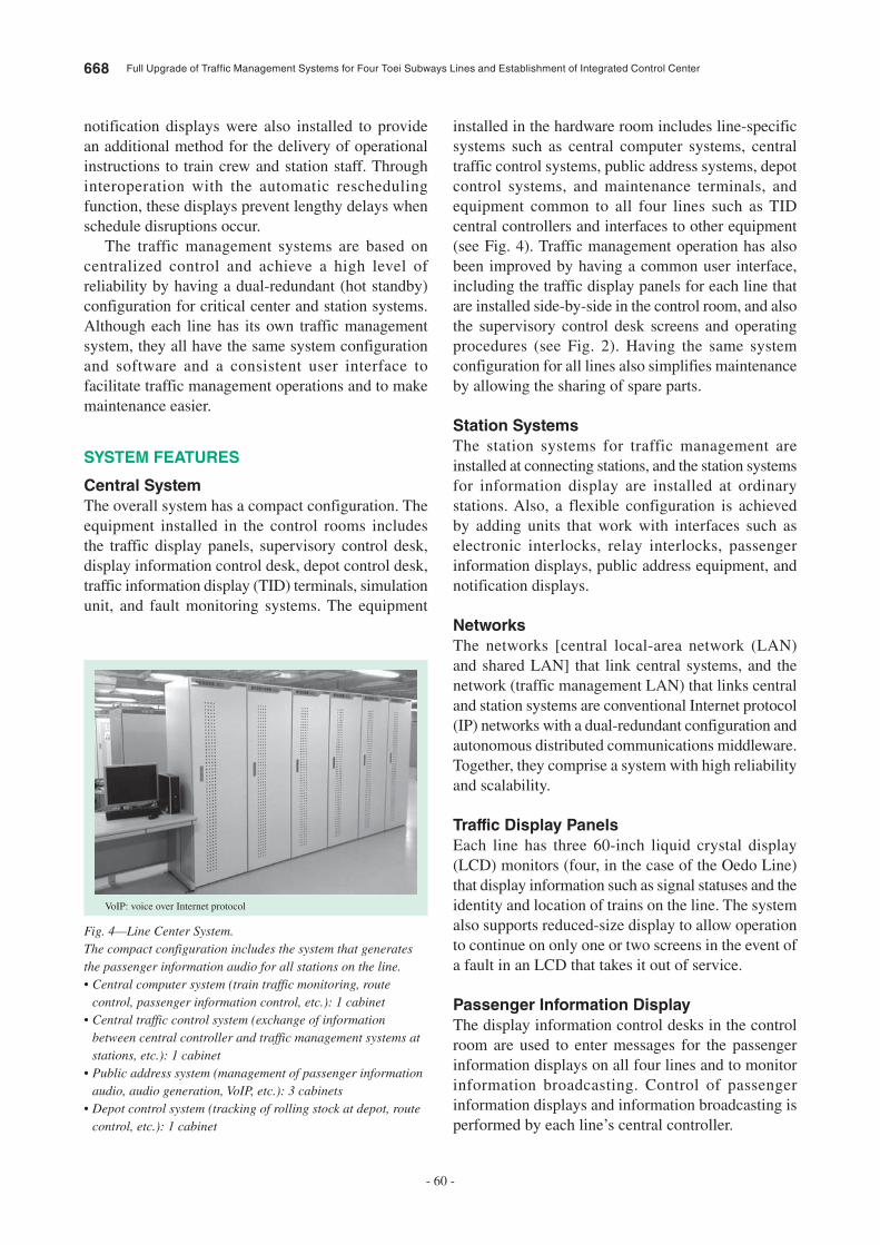
668 Full Upgrade of Traffic Management Systems for Four Toei Subways Lines and Establishment of Integrated Control Center
- 60 -
notification displays were also installed to provide an additional method for the delivery of operational instructions to train crew and station staff. Through interoperation with the automatic rescheduling function, these displays prevent lengthy delays when schedule disruptions occur.
The traffic management systems are based on centralized control and achieve a high level of reliability by having a dual-redundant (hot standby) configuration for critical center and station systems. Although each line has its own traffic management system, they all have the same system configuration and software and a consistent user interface to facilitate traffic management operations and to make maintenance easier.
SYSTEM FEATURES
Central System
The overall system has a compact configuration. The equipment installed in the control rooms includes the traffic display panels, supervisory control desk, display information control desk, depot control desk, traffic information display (TID) terminals, simulation unit, and fault monitoring systems. The equipment
installed in the hardware room includes line-specific systems such as central computer systems, central traffic control systems, public address systems, depot control systems, and maintenance terminals, and equipment common to all four lines such as TID central controllers and interfaces to other equipment (see Fig. 4). Traffic management operation has also been improved by having a common user interface, including the traffic display panels for each line that are installed side-by-side in the control room, and also the supervisory control desk screens and operating procedures (see Fig. 2). Having the same system configuration for all lines also simplifies maintenance by allowing the sharing of spare parts.
Station Systems
The station systems for traffic management are installed at connecting stations, and the station systems for information display are installed at ordinary stations. Also, a flexible configuration is achieved by adding units that work with interfaces such as electronic interlocks, relay interlocks, passenger information displays, public address equipment, and notification displays.
Networks
The networks [central local-area network (LAN) and shared LAN] that link central systems, and the network (traffic management LAN) that links central and station systems are conventional Internet protocol (IP) networks with a dual-redundant configuration and autonomous distributed communications middleware. Together, they comprise a system with high reliability and scalability.
Traffic Display Panels
Each line has three 60-inch liquid crystal display (LCD) monitors (four, in the case of the Oedo Line) that display information such as signal statuses and the identity and location of trains on the line. The system also supports reduced-size display to allow operation to continue on only one or two screens in the event of a fault in an LCD that takes it out of service.
Passenger Information Display
The display information control desks in the control room are used to enter messages for the passenger information displays on all four lines and to monitor information broadcasting. Control of passenger information displays and information broadcasting is performed by each line’s central controller.
Fig. 4—Line Center System.The compact configuration includes the system that generates the passenger information audio for all stations on the line.• Central computer system (train traffic monitoring, route
control, passenger information control, etc.): 1 cabinet• Central traffic control system (exchange of information
between central controller and traffic management systems at stations, etc.): 1 cabinet
• Public address system (management of passenger information audio, audio generation, VoIP, etc.): 3 cabinets
• Depot control system (tracking of rolling stock at depot, route control, etc.): 1 cabinet
VoIP: voice over Internet protocol
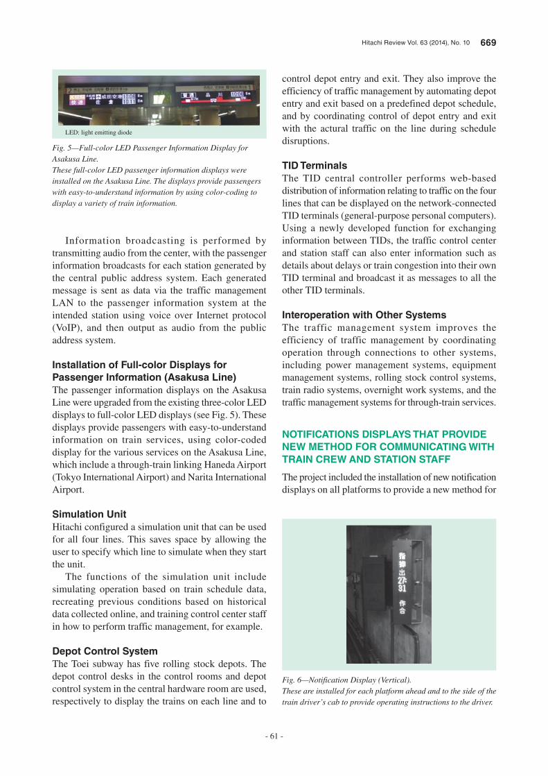
Hitachi Review Vol. 63 (2014), No. 10 669
- 61 -
Information broadcasting is performed by transmitting audio from the center, with the passenger information broadcasts for each station generated by the central public address system. Each generated message is sent as data via the traffic management LAN to the passenger information system at the intended station using voice over Internet protocol (VoIP), and then output as audio from the public address system.
Installation of Full-color Displays for
Passenger Information (Asakusa Line)
The passenger information displays on the Asakusa Line were upgraded from the existing three-color LED displays to full-color LED displays (see Fig. 5). These displays provide passengers with easy-to-understand information on train services, using color-coded display for the various services on the Asakusa Line, which include a through-train linking Haneda Airport (Tokyo International Airport) and Narita International Airport.
Simulation Unit
Hitachi configured a simulation unit that can be used for all four lines. This saves space by allowing the user to specify which line to simulate when they start the unit.
The functions of the simulation unit include simulating operation based on train schedule data, recreating previous conditions based on historical data collected online, and training control center staff in how to perform traffic management, for example.
Depot Control System
The Toei subway has five rolling stock depots. The depot control desks in the control rooms and depot control system in the central hardware room are used, respectively to display the trains on each line and to
control depot entry and exit. They also improve the efficiency of traffic management by automating depot entry and exit based on a predefined depot schedule, and by coordinating control of depot entry and exit with the actural traffic on the line during schedule disruptions.
TID Terminals
The TID central controller performs web-based distribution of information relating to traffic on the four lines that can be displayed on the network-connected TID terminals (general-purpose personal computers). Using a newly developed function for exchanging information between TIDs, the traffic control center and station staff can also enter information such as details about delays or train congestion into their own TID terminal and broadcast it as messages to all the other TID terminals.
Interoperation with Other Systems
The traffic management system improves the efficiency of traffic management by coordinating operation through connections to other systems, including power management systems, equipment management systems, rolling stock control systems, train radio systems, overnight work systems, and the traffic management systems for through-train services.
NOTIFICATIONS DISPLAYS THAT PROVIDE
NEW METHOD FOR COMMUNICATING WITH
TRAIN CREW AND STATION STAFF
The project included the installation of new notification displays on all platforms to provide a new method for
Fig. 5—Full-color LED Passenger Information Display for Asakusa Line.These full-color LED passenger information displays were installed on the Asakusa Line. The displays provide passengers with easy-to-understand information by using color-coding to display a variety of train information.
LED: light emitting diode
Fig. 6—Notification Display (Vertical).These are installed for each platform ahead and to the side of the train driver’s cab to provide operating instructions to the driver.
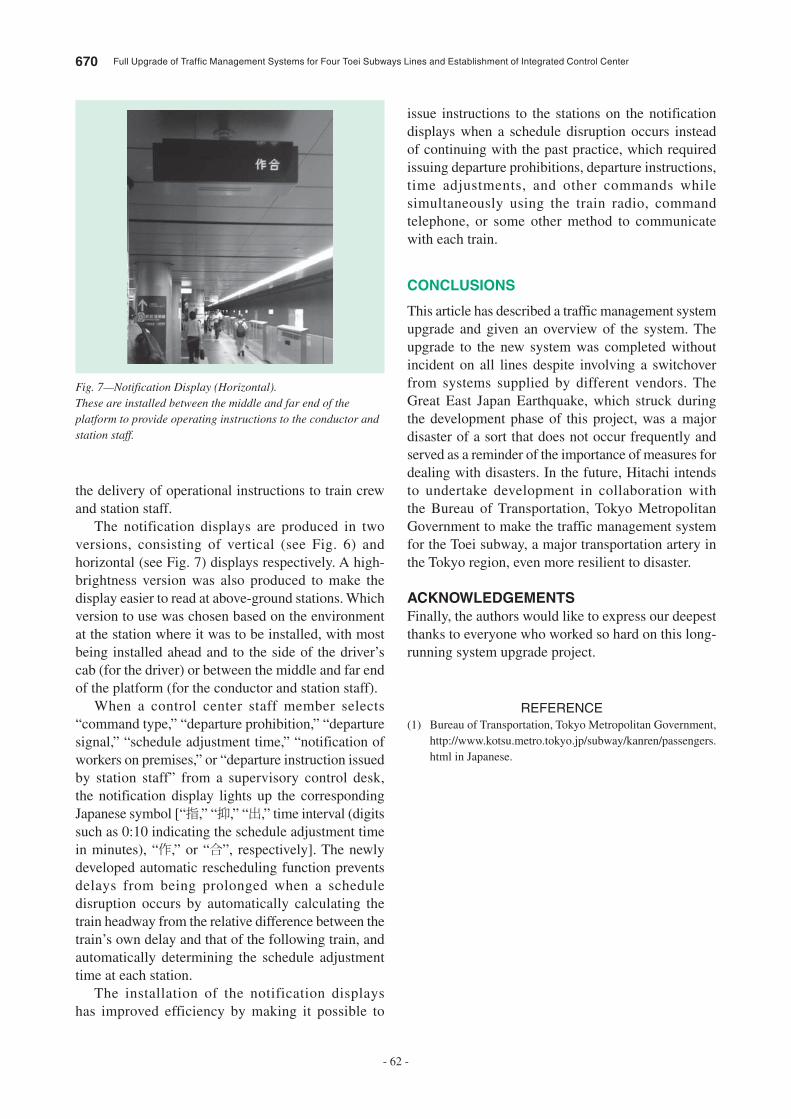
670 Full Upgrade of Traffic Management Systems for Four Toei Subways Lines and Establishment of Integrated Control Center
- 62 -
issue instructions to the stations on the notification displays when a schedule disruption occurs instead of continuing with the past practice, which required issuing departure prohibitions, departure instructions, time adjustments, and other commands while simultaneously using the train radio, command telephone, or some other method to communicate with each train.
CONCLUSIONS
This article has described a traffic management system upgrade and given an overview of the system. The upgrade to the new system was completed without incident on all lines despite involving a switchover from systems supplied by different vendors. The Great East Japan Earthquake, which struck during the development phase of this project, was a major disaster of a sort that does not occur frequently and served as a reminder of the importance of measures for dealing with disasters. In the future, Hitachi intends to undertake development in collaboration with the Bureau of Transportation, Tokyo Metropolitan Government to make the traffic management system for the Toei subway, a major transportation artery in the Tokyo region, even more resilient to disaster.
ACKNOWLEDGEMENTS
Finally, the authors would like to express our deepest thanks to everyone who worked so hard on this long-running system upgrade project.
REFERENCE
(1) Bureau of Transportation, Tokyo Metropolitan Government, http://www.kotsu.metro.tokyo.jp/subway/kanren/passengers.html in Japanese.
the delivery of operational instructions to train crew and station staff.
The notification displays are produced in two versions, consisting of vertical (see Fig. 6) and horizontal (see Fig. 7) displays respectively. A high-brightness version was also produced to make the display easier to read at above-ground stations. Which version to use was chosen based on the environment at the station where it was to be installed, with most being installed ahead and to the side of the driver’s cab (for the driver) or between the middle and far end of the platform (for the conductor and station staff).
When a control center staff member selects “command type,” “departure prohibition,” “departure signal,” “schedule adjustment time,” “notification of workers on premises,” or “departure instruction issued by station staff” from a supervisory control desk, the notification display lights up the corresponding Japanese symbol [“指,” “抑,” “出,” time interval (digits such as 0:10 indicating the schedule adjustment time in minutes), “作,” or “合”, respectively]. The newly developed automatic rescheduling function prevents delays from being prolonged when a schedule disruption occurs by automatically calculating the train headway from the relative difference between the train’s own delay and that of the following train, and automatically determining the schedule adjustment time at each station.
The installation of the notification displays has improved efficiency by making it possible to
Fig. 7—Notification Display (Horizontal).These are installed between the middle and far end of the platform to provide operating instructions to the conductor and station staff.
Hitachi Review Vol. 63 (2014), No. 10 671
- 63 -
Kenichi Okada
Signaling Systems Design Department, Mito Transportation Systems Product Division, Rail Systems Company, Hitachi, Ltd. He is currently engaged in the development of traffic management systems for railways.
Shoji Harada
Signaling Systems Design Department, Mito Transportation Systems Product Division, Rail Systems Company, Hitachi, Ltd. He is currently engaged in the development of traffic management systems for railways.
Daisuke Sakuta
Transport Management Systems & Solution Department, Transport Management & Control Systems Division, Rail Systems Company, Hitachi, Ltd. He is currently engaged in the development of traffic management systems for railways and other transportation systems.
Katsumi Kashimura
Signaling Systems Design Department, Mito Transportation Systems Product Division, Rail Systems Company, Hitachi, Ltd. He is currently engaged in the development of traffic management systems for railways.
ABOUT THE AUTHORS

672 Hitachi Review Vol. 63 (2014), No. 10
- 64 -
Featured Articles
Development of On-board Passenger Information Display
Kiaki Matsumoto
Koji Nakada
Kazuya Azuma
Hiroshi Hatakeyama
Tatsuya Tokunaga
Kazunori Takahashi
OVERVIEW: Advances in ICT and display panels in recent years have led to on-board passenger information displays becoming commonplace on commuter trains. Hitachi commenced serious development in 2006 with the development of an on-board passenger information display based on the concept of experience design from a user’s perspective and achieving a high level of equipment utilization by adopting the autonomous decentralized architecture that was already being used for our traffic management systems. This involved performing information design (visibility and intelligibility) for the passenger information display to suit the diverse variety of people who ride on commuter trains. Hitachi adopted open system interfaces and software to implement the functions of a total system (including both on-board and wayside systems) that would be able to grow over time without becoming obsolete.
INTRODUCTION
PASSENGER information displays have become a common sight in railway stations and trains in recent years. On trains, in particular, there is growing use of liquid crystal displays (LCDs) to present information. Hitachi has developed on-board passenger information displays based on the concept of formatting the information that train users need in order to get to their destinations in ways that suit their needs, and displaying the destination, service type, next station, current time, and other details so that they can make the journey with confidence, safety, comfort, and convenience.
ARCHITECTURE OF HITACHI’S ON-BOARD PASSENGER INFORMATION DISPLAY SYSTEM
Hitachi has always adopted autonomous and decentralized architecture for our railway applications (particularly traffic management systems), with open interfaces and software used to implement the functions of a total system that can grow over time without becoming obsolete. While this autonomous decentralized design provides excellent reliability with a very high degree of redundancy due to each device that has its own central processing unit (CPU), the disadvantage of every device having a CPU is higher cost. Nevertheless, Hitachi has decided to use an autonomous decentralized design for on-board
passenger information display systems, considering it to be the best architecture given the advances in technology that have reduced the size and price of CPUs, and taking account of factors such as the difficult environment for the distribution of video signal around a train, issues with noise, future requirements for higher definition video reproduction, and ease of maintenance.
System Confi gurationThe autonomous decentralized system consists of a host system, client units, smart LCD display units, and an on-board Worldwide Interoperability for Microwave Access (WiMAX*1) unit for communicating with the wayside system. Fig. 1 shows the system block diagram.
Host SystemEach train has a single host system with two main functions. The first is to receive advertising contents from the wayside system via the on-board WiMAX unit. The second is to store content data that will be required by client devices in the event they fail. Fig. 2 shows the host system hardware.
The host system communicates with the wayside system via the on-board WiMAX unit to download schedules and content data. The use of WiMAX allows communications to occur over a wide area and at high speed, whether the train is moving or stopped.
*1 WiMAX is a trademark or registered trademark of the WiMAX Forum.
Hitachi Review Vol. 63 (2014), No. 10 673
- 65 -
Compared with the previous use of wireless local area networks (LANs), millimeter-band radio, and other wireless systems that worked in only particular locations, this has considerably reduced the time taken to complete the distribution of a new update. Also, content can be updated even when the train is at the depot as long as it is within the WiMAX radio coverage area. Content updating is fast and efficient. Even if communication is interrupted during a download, the download will restart from where it left off once communication is restored.
Furthermore, if a client unit or LCD display unit managed by the host system develops a fault, its data can be resent by the host system without downloading the data again from the wayside system. If the client unit in car number 6, for example, has a fault, the faulty unit can be identified from the train information management system screen and replaced with a spare. However, the replacement unit will not have the correct Internet protocol (IP) address, passenger information display settings, advertising content, and schedule data. For a technician to set this information, it would require specialist knowledge and it would take the technician time to perform the required operations. Instead, the host system has a function for automatically transmitting these settings and other data. When a unit is initialized from the train information management system screen, the system automatically identifies where each device is installed and sets the IP address accordingly. That is, the replaced client unit is detected as being in car 6 and the host system sends it the content data it requires. This improves maintenance productivity because it simplifies the job of the technician replacing the faulty unit and prevents problems due to incorrect settings and so on.
Client UnitEach car has a single client unit with three main functions. The first is to receive advertising content from the host system and forward it to the LCD display units. The second is to store the required content data in the event that an LCD display unit fails (similar to the equivalent function on the host system). The third
On-boardWiMAX unit
Host system
Smart LCDdisplay units
Client unit
Smart LCDdisplay units
Client unit
Train informationmanagement system
Smart LCDdisplay units
Client unit
Train informationmanagement system
Smart LCDdisplay units
Client unit
Train informationmanagement system
Development scope
Train information management system
Fig. 1—Block Diagram of On-board Passenger Information Display System.The on-board passenger information display consists of a host system, client units, smart LCD display units, and on-board WiMAX unit.
WiMAX: Worldwide Interoperability for Microwave Access LCD: liquid crystal display
Fig. 2—Host System.The host system receives display information from the wayside system, and stores and forwards it to the client units.
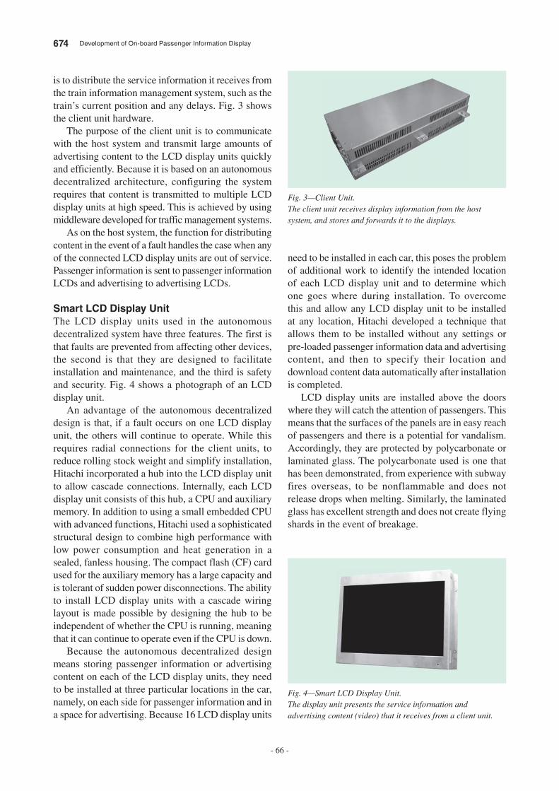
674 Development of On-board Passenger Information Display
- 66 -
is to distribute the service information it receives from the train information management system, such as the train’s current position and any delays. Fig. 3 shows the client unit hardware.
The purpose of the client unit is to communicate with the host system and transmit large amounts of advertising content to the LCD display units quickly and efficiently. Because it is based on an autonomous decentralized architecture, configuring the system requires that content is transmitted to multiple LCD display units at high speed. This is achieved by using middleware developed for traffic management systems.
As on the host system, the function for distributing content in the event of a fault handles the case when any of the connected LCD display units are out of service. Passenger information is sent to passenger information LCDs and advertising to advertising LCDs.
Smart LCD Display UnitThe LCD display units used in the autonomous decentralized system have three features. The first is that faults are prevented from affecting other devices, the second is that they are designed to facilitate installation and maintenance, and the third is safety and security. Fig. 4 shows a photograph of an LCD display unit.
An advantage of the autonomous decentralized design is that, if a fault occurs on one LCD display unit, the others will continue to operate. While this requires radial connections for the client units, to reduce rolling stock weight and simplify installation, Hitachi incorporated a hub into the LCD display unit to allow cascade connections. Internally, each LCD display unit consists of this hub, a CPU and auxiliary memory. In addition to using a small embedded CPU with advanced functions, Hitachi used a sophisticated structural design to combine high performance with low power consumption and heat generation in a sealed, fanless housing. The compact flash (CF) card used for the auxiliary memory has a large capacity and is tolerant of sudden power disconnections. The ability to install LCD display units with a cascade wiring layout is made possible by designing the hub to be independent of whether the CPU is running, meaning that it can continue to operate even if the CPU is down.
Because the autonomous decentralized design means storing passenger information or advertising content on each of the LCD display units, they need to be installed at three particular locations in the car, namely, on each side for passenger information and in a space for advertising. Because 16 LCD display units
need to be installed in each car, this poses the problem of additional work to identify the intended location of each LCD display unit and to determine which one goes where during installation. To overcome this and allow any LCD display unit to be installed at any location, Hitachi developed a technique that allows them to be installed without any settings or pre-loaded passenger information data and advertising content, and then to specify their location and download content data automatically after installation is completed.
LCD display units are installed above the doors where they will catch the attention of passengers. This means that the surfaces of the panels are in easy reach of passengers and there is a potential for vandalism. Accordingly, they are protected by polycarbonate or laminated glass. The polycarbonate used is one that has been demonstrated, from experience with subway fires overseas, to be nonflammable and does not release drops when melting. Similarly, the laminated glass has excellent strength and does not create flying shards in the event of breakage.
Fig. 3—Client Unit.The client unit receives display information from the host system, and stores and forwards it to the displays.
Fig. 4—Smart LCD Display Unit.The display unit presents the service information and advertising content (video) that it receives from a client unit.

Hitachi Review Vol. 63 (2014), No. 10 675
- 67 -
PASSENGER INFORMATION
The passenger information display uses both slide-show and object-based formats. The slide-show format involves the scheduled and sequential display of predefined images and therefore can be produced without a complicated program. The problem with this format, however, is the large volume of schedules and images required, which makes content production time-consuming and maintenance costly. This applies in particular to long or complex railway lines that have a number of different service types, or where trains are separated or coupled, for example.
The object-based display format, in contrast, requires a high-performance CPU, sophisticated middleware, and complex application programs. It also delivers better presentation and lower maintenance costs than the slide-show format, being able to display animated passenger information and allowing the
consolidated management and modification of the associated symbols (images).
LCD display units support the object-based format to provide sophisticated display of passenger information with high visibility and intelligibility.
Universal design considerations are incorporated into the design of information for display on passenger information screens in three different ways. The first is the viewing angle and text size. Designs that can be read easily from any viewing location are achieved by dividing the distance between the passenger and LCD display unit into three ranges and selecting the text size based on the priority of the information to be conveyed (see Fig. 5). The second is the legibility and visibility of the text. The designs are required to have a contrast ratio between the character color and background color of 3:1 or better, with a target of 5:1, so that it is easy (for the elderly) to read the information. The third is to take account of the elderly and people with color-impaired vision*2. The designs avoid color combinations that people in this
Level BLevel C
Level A
Level ALevel B
Level B
Level C
2 m 1 m 5 m
Fig. 5—Viewing Angle and Text Size.The design divides the distance between the passenger and display unit into three ranges and uses a text size based on the priority of the information.
Fig. 6—Consideration for Elderly People and People with Color-impaired Vision.Color displays are checked in black and white, and adjusted to use colors in ways that are easy for the elderly people and people with color-impaired vision to distinguish.
*2 Meaning limited ability to distinguish between certain colors. Other terms include color-vision deficiency, color-blindness, and dyschromatopsia.
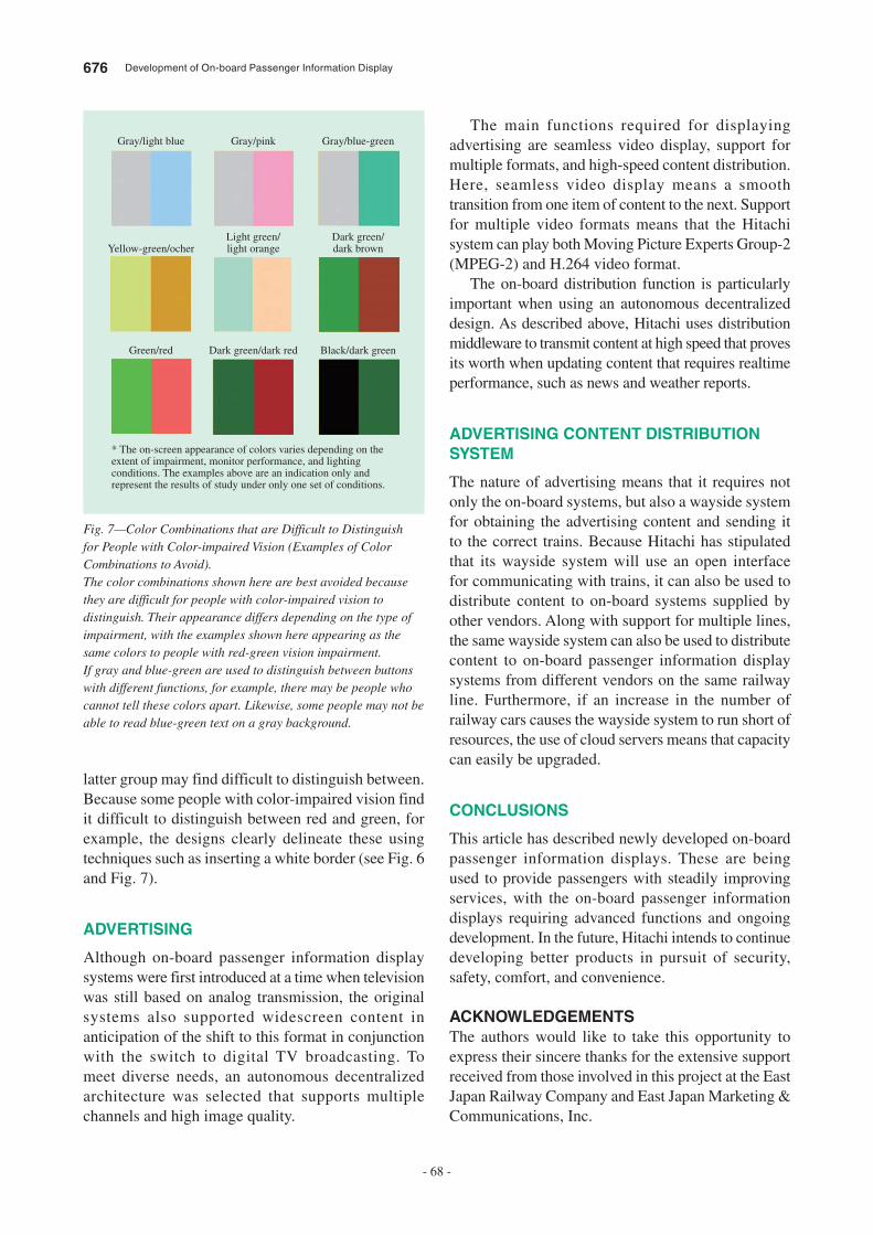
676 Development of On-board Passenger Information Display
- 68 -
The main functions required for displaying advertising are seamless video display, support for multiple formats, and high-speed content distribution. Here, seamless video display means a smooth transition from one item of content to the next. Support for multiple video formats means that the Hitachi system can play both Moving Picture Experts Group-2 (MPEG-2) and H.264 video format.
The on-board distribution function is particularly important when using an autonomous decentralized design. As described above, Hitachi uses distribution middleware to transmit content at high speed that proves its worth when updating content that requires realtime performance, such as news and weather reports.
ADVERTISING CONTENT DISTRIBUTION SYSTEM
The nature of advertising means that it requires not only the on-board systems, but also a wayside system for obtaining the advertising content and sending it to the correct trains. Because Hitachi has stipulated that its wayside system will use an open interface for communicating with trains, it can also be used to distribute content to on-board systems supplied by other vendors. Along with support for multiple lines, the same wayside system can also be used to distribute content to on-board passenger information display systems from different vendors on the same railway line. Furthermore, if an increase in the number of railway cars causes the wayside system to run short of resources, the use of cloud servers means that capacity can easily be upgraded.
CONCLUSIONS
This article has described newly developed on-board passenger information displays. These are being used to provide passengers with steadily improving services, with the on-board passenger information displays requiring advanced functions and ongoing development. In the future, Hitachi intends to continue developing better products in pursuit of security, safety, comfort, and convenience.
ACKNOWLEDGEMENTSThe authors would like to take this opportunity to express their sincere thanks for the extensive support received from those involved in this project at the East Japan Railway Company and East Japan Marketing & Communications, Inc.
latter group may find difficult to distinguish between. Because some people with color-impaired vision find it difficult to distinguish between red and green, for example, the designs clearly delineate these using techniques such as inserting a white border (see Fig. 6 and Fig. 7).
ADVERTISING
Although on-board passenger information display systems were first introduced at a time when television was still based on analog transmission, the original systems also supported widescreen content in anticipation of the shift to this format in conjunction with the switch to digital TV broadcasting. To meet diverse needs, an autonomous decentralized architecture was selected that supports multiple channels and high image quality.
Gray/light blue Gray/pink Gray/blue-green
Yellow-green/ocherLight green/light orange
Dark green/dark brown
Green/red Dark green/dark red Black/dark green
* The on-screen appearance of colors varies depending on the extent of impairment, monitor performance, and lighting conditions. The examples above are an indication only and represent the results of study under only one set of conditions.
Fig. 7—Color Combinations that are Difficult to Distinguish for People with Color-impaired Vision (Examples of Color Combinations to Avoid).The color combinations shown here are best avoided because they are difficult for people with color-impaired vision to distinguish. Their appearance differs depending on the type of impairment, with the examples shown here appearing as the same colors to people with red-green vision impairment.If gray and blue-green are used to distinguish between buttons with different functions, for example, there may be people who cannot tell these colors apart. Likewise, some people may not be able to read blue-green text on a gray background.
Hitachi Review Vol. 63 (2014), No. 10 677
- 69 -
(2) Products & Solutions web page, Infrastructure Systems Company, Hitachi, Ltd. http://www.hitachi.com/businesses/infrastructure/product_solution/mobility/passenger_information/panel.html
REFERENCES
(1) S. Iwamura et al., “Hitachi’s ATI Series Satisfies All the Needs of Train-compartment Information Control,” Hitachi Review 57, pp. 46–50 (Mar. 2008).
Koji Nakada
Transportation Information & Control Systems Division, Infrastructure Systems Company, Hitachi, Ltd. He is currently engaged in the development of passenger information systems.
Hiroshi Hatakeyama
Control System Platform Development Division, Infrastructure Systems Company, Hitachi, Ltd. He is currently engaged in the development of passenger information systems.
Kazunori Takahashi
JR Systems Department, Sales & Marketing Division, Rail Systems Company, Hitachi, Ltd. He is currently engaged in sales to the East Japan Railway Company.
Kiaki Matsumoto
Transport Management & Control Systems Division, Rail Systems Company, Hitachi, Ltd. He is currently engaged in the development of passenger information systems.
Kazuya Azuma
Transportation Information & Control Systems Division, Infrastructure Systems Company, Hitachi, Ltd. He is currently engaged in the development of passenger information systems.
Tatsuya Tokunaga
1st Unit, Information Design Department, Design Division, Hitachi, Ltd. He is currently engaged in the development of user interface designs for railway systems.
ABOUT THE AUTHORS
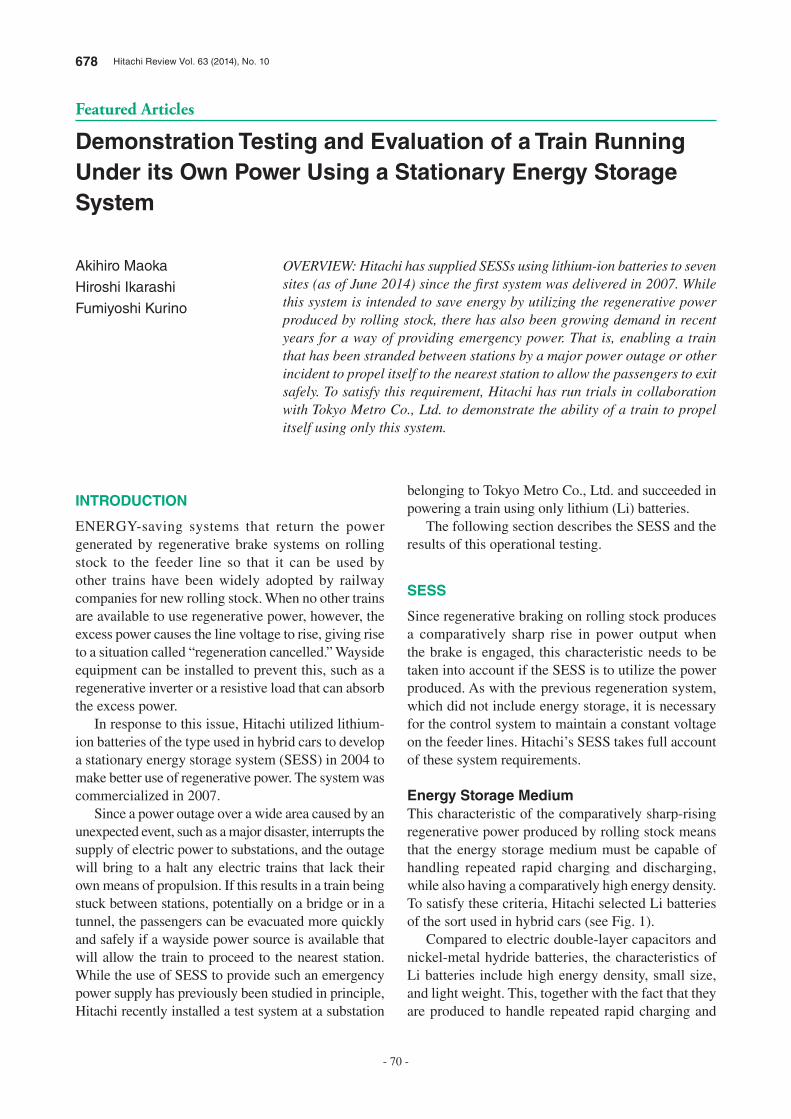
678 Hitachi Review Vol. 63 (2014), No. 10
- 70 -
Featured Articles
Demonstration Testing and Evaluation of a Train Running Under its Own Power Using a Stationary Energy Storage System
Akihiro Maoka
Hiroshi Ikarashi
Fumiyoshi Kurino
OVERVIEW: Hitachi has supplied SESSs using lithium-ion batteries to seven sites (as of June 2014) since the first system was delivered in 2007. While this system is intended to save energy by utilizing the regenerative power produced by rolling stock, there has also been growing demand in recent years for a way of providing emergency power. That is, enabling a train that has been stranded between stations by a major power outage or other incident to propel itself to the nearest station to allow the passengers to exit safely. To satisfy this requirement, Hitachi has run trials in collaboration with Tokyo Metro Co., Ltd. to demonstrate the ability of a train to propel itself using only this system.
INTRODUCTION
ENERGY-saving systems that return the power
generated by regenerative brake systems on rolling
stock to the feeder line so that it can be used by
other trains have been widely adopted by railway
companies for new rolling stock. When no other trains
are available to use regenerative power, however, the
excess power causes the line voltage to rise, giving rise
to a situation called “regeneration cancelled.” Wayside
equipment can be installed to prevent this, such as a
regenerative inverter or a resistive load that can absorb
the excess power.
In response to this issue, Hitachi utilized lithium-
ion batteries of the type used in hybrid cars to develop
a stationary energy storage system (SESS) in 2004 to
make better use of regenerative power. The system was
commercialized in 2007.
Since a power outage over a wide area caused by an
unexpected event, such as a major disaster, interrupts the
supply of electric power to substations, and the outage
will bring to a halt any electric trains that lack their
own means of propulsion. If this results in a train being
stuck between stations, potentially on a bridge or in a
tunnel, the passengers can be evacuated more quickly
and safely if a wayside power source is available that
will allow the train to proceed to the nearest station.
While the use of SESS to provide such an emergency
power supply has previously been studied in principle,
Hitachi recently installed a test system at a substation
belonging to Tokyo Metro Co., Ltd. and succeeded in
powering a train using only lithium (Li) batteries.
The following section describes the SESS and the
results of this operational testing.
SESS
Since regenerative braking on rolling stock produces
a comparatively sharp rise in power output when
the brake is engaged, this characteristic needs to be
taken into account if the SESS is to utilize the power
produced. As with the previous regeneration system,
which did not include energy storage, it is necessary
for the control system to maintain a constant voltage
on the feeder lines. Hitachi’s SESS takes full account
of these system requirements.
Energy Storage MediumThis characteristic of the comparatively sharp-rising
regenerative power produced by rolling stock means
that the energy storage medium must be capable of
handling repeated rapid charging and discharging,
while also having a comparatively high energy density.
To satisfy these criteria, Hitachi selected Li batteries
of the sort used in hybrid cars (see Fig. 1).
Compared to electric double-layer capacitors and
nickel-metal hydride batteries, the characteristics of
Li batteries include high energy density, small size,
and light weight. This, together with the fact that they
are produced to handle repeated rapid charging and
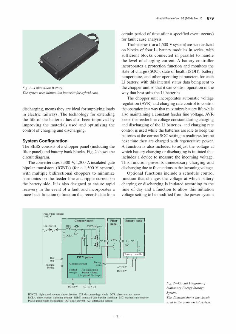
Hitachi Review Vol. 63 (2014), No. 10 679
- 71 -
discharging, means they are ideal for supplying loads
in electric railways. The technology for extending
the life of the batteries has also been improved by
improving the materials used and optimizing the
control of charging and discharging.
System Confi gurationThe SESS consists of a chopper panel (including the
filter panel) and battery bank blocks. Fig. 2 shows the
circuit diagram.
The converter uses 3,300-V, 1,200-A insulated-gate
bipolar transistors (IGBTs) (for a 1,500-V system),
with multiple bidirectional choppers to minimize
harmonics on the feeder line and ripple current on
the battery side. It is also designed to ensure rapid
recovery in the event of a fault and incorporates a
trace-back function (a function that records data for a
certain period of time after a specified event occurs)
for fault cause analysis.
The batteries (for a 1,500-V system) are standardized
on blocks of four Li battery modules in series, with
sufficient blocks connected in parallel to handle
the level of charging current. A battery controller
incorporates a protection function and monitors the
state of charge (SOC), state of health (SOH), battery
temperature, and other operating parameters for each
Li battery, with this internal status data being sent to
the chopper unit so that it can control operation in the
way that best suits the Li batteries.
The chopper unit incorporates automatic voltage
regulation (AVR) and charging rate control to control
the operation in a way that maximizes battery life while
also maintaining a constant feeder line voltage. AVR
keeps the feeder line voltage constant during charging
and discharging of the Li batteries, and charging rate
control is used while the batteries are idle to keep the
batteries at the correct SOC setting in readiness for the
next time they are charged with regenerative power.
A function is also included to adjust the voltage at
which battery charging or discharging is initiated that
includes a device to measure the incoming voltage.
This function prevents unnecessary charging and
discharging due to fluctuations in the incoming voltage.
Optional functions include a schedule control
function that changes the voltage at which battery
charging or discharging is initiated according to the
time of day and a function to allow this initiation
voltage setting to be modified from the power system
Fig. 1—Lithium-ion Battery.The system uses lithium-ion batteries for hybrid cars.
Feeder line voltage: 1,650 V
Chopper panel
PWM pulses
Control circuitBattery
status
For augmentingbusbar voltage
(charge and discharge)
Controlvoltage
RunStop
RunningTesting
DC100 V AC100 V 3φ
Filterpanel
Battery bank
DS HSVCB
DCLA
DCR
MC
IGBT chopper
MC
AC100 V
DC100 V
Battery controller
+
−
HSVCB: high-speed vacuum circuit breaker DS: disconnecting switch DCR: direct-current reactor DCLA: direct-current lightning arrester IGBT: insulated-gate bipolar transistor MC: mechanical contactor PWM: pulse-width modulation DC: direct current AC: alternating current
Fig. 2—Circuit Diagram of Stationary Energy Storage System.The diagram shows the circuit used in the commercial system.
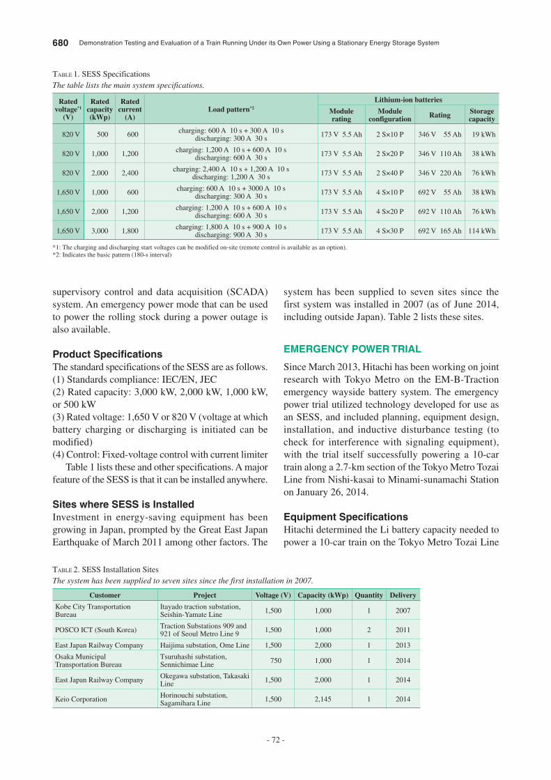
680 Demonstration Testing and Evaluation of a Train Running Under its Own Power Using a Stationary Energy Storage System
- 72 -
supervisory control and data acquisition (SCADA)
system. An emergency power mode that can be used
to power the rolling stock during a power outage is
also available.
Product Specifi cationsThe standard specifications of the SESS are as follows.
(1) Standards compliance: IEC/EN, JEC
(2) Rated capacity: 3,000 kW, 2,000 kW, 1,000 kW,
or 500 kW
(3) Rated voltage: 1,650 V or 820 V (voltage at which
battery charging or discharging is initiated can be
modified)
(4) Control: Fixed-voltage control with current limiter
Table 1 lists these and other specifications. A major
feature of the SESS is that it can be installed anywhere.
Sites where SESS is InstalledInvestment in energy-saving equipment has been
growing in Japan, prompted by the Great East Japan
Earthquake of March 2011 among other factors. The
system has been supplied to seven sites since the
first system was installed in 2007 (as of June 2014,
including outside Japan). Table 2 lists these sites.
EMERGENCY POWER TRIAL
Since March 2013, Hitachi has been working on joint
research with Tokyo Metro on the EM-B-Traction
emergency wayside battery system. The emergency
power trial utilized technology developed for use as
an SESS, and included planning, equipment design,
installation, and inductive disturbance testing (to
check for interference with signaling equipment),
with the trial itself successfully powering a 10-car
train along a 2.7-km section of the Tokyo Metro Tozai
Line from Nishi-kasai to Minami-sunamachi Station
on January 26, 2014.
Equipment Specifi cationsHitachi determined the Li battery capacity needed to
power a 10-car train on the Tokyo Metro Tozai Line
Rated voltage*1
(V)
Rated capacity (kWp)
Rated current
(A)Load pattern*2
Lithium-ion batteries
Modulerating
Module configuration Rating Storage
capacity
820 V 500 600charging: 600 A 10 s + 300 A 10 s
discharging: 300 A 30 s173 V 5.5 Ah 2 S×10 P 346 V 55 Ah 19 kWh
820 V 1,000 1,200charging: 1,200 A 10 s + 600 A 10 s
discharging: 600 A 30 s173 V 5.5 Ah 2 S×20 P 346 V 110 Ah 38 kWh
820 V 2,000 2,400charging: 2,400 A 10 s + 1,200 A 10 s
discharging: 1,200 A 30 s173 V 5.5 Ah 2 S×40 P 346 V 220 Ah 76 kWh
1,650 V 1,000 600charging: 600 A 10 s + 3000 A 10 s
discharging: 300 A 30 s173 V 5.5 Ah 4 S×10 P 692 V 55 Ah 38 kWh
1,650 V 2,000 1,200charging: 1,200 A 10 s + 600 A 10 s
discharging: 600 A 30 s173 V 5.5 Ah 4 S×20 P 692 V 110 Ah 76 kWh
1,650 V 3,000 1,800charging: 1,800 A 10 s + 900 A 10 s
discharging: 900 A 30 s173 V 5.5 Ah 4 S×30 P 692 V 165 Ah 114 kWh
TABLE 1. SESS Specifications
The table lists the main system specifications.
*1: The charging and discharging start voltages can be modified on-site (remote control is available as an option).*2: Indicates the basic pattern (180-s interval)
Customer Project Voltage (V) Capacity (kWp) Quantity Delivery
Kobe City Transportation Bureau
Itayado traction substation, Seishin-Yamate Line
1,500 1,000 1 2007
POSCO ICT (South Korea)Traction Substations 909 and 921 of Seoul Metro Line 9
1,500 1,000 2 2011
East Japan Railway Company Haijima substation, Ome Line 1,500 2,000 1 2013
Osaka Municipal Transportation Bureau
Tsuruhashi substation, Sennichimae Line
750 1,000 1 2014
East Japan Railway CompanyOkegawa substation, Takasaki Line
1,500 2,000 1 2014
Keio CorporationHorinouchi substation, Sagamihara Line
1,500 2,145 1 2014
TABLE 2. SESS Installation Sites
The system has been supplied to seven sites since the first installation in 2007.
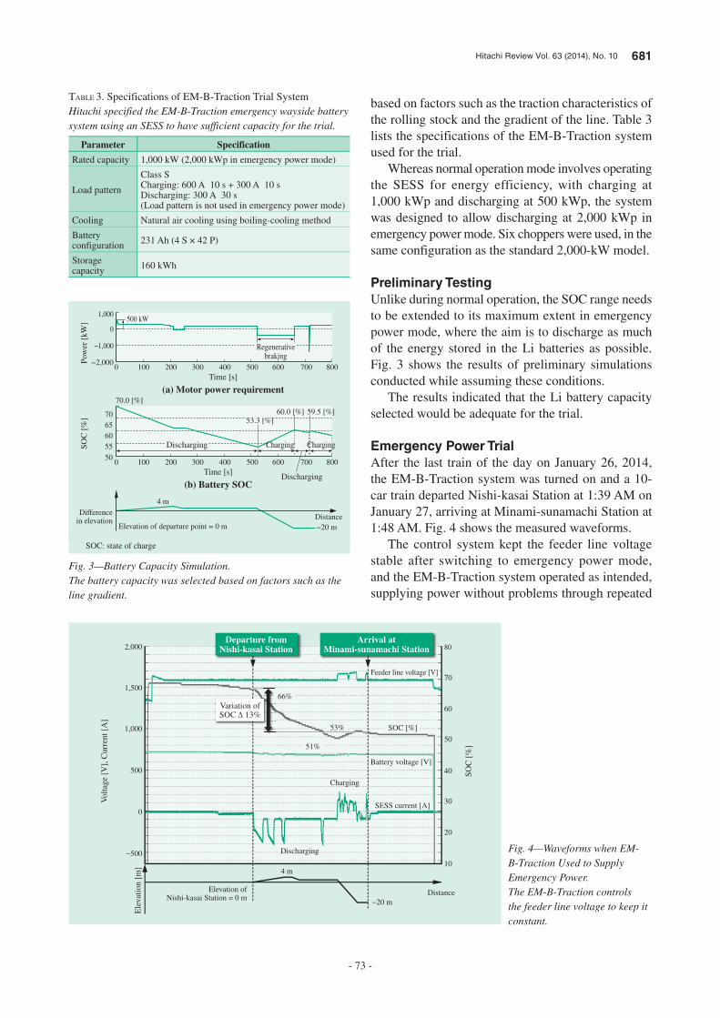
Hitachi Review Vol. 63 (2014), No. 10 681
- 73 -
based on factors such as the traction characteristics of
the rolling stock and the gradient of the line. Table 3
lists the specifications of the EM-B-Traction system
used for the trial.
Whereas normal operation mode involves operating
the SESS for energy efficiency, with charging at
1,000 kWp and discharging at 500 kWp, the system
was designed to allow discharging at 2,000 kWp in
emergency power mode. Six choppers were used, in the
same configuration as the standard 2,000-kW model.
Preliminary TestingUnlike during normal operation, the SOC range needs
to be extended to its maximum extent in emergency
power mode, where the aim is to discharge as much
of the energy stored in the Li batteries as possible.
Fig. 3 shows the results of preliminary simulations
conducted while assuming these conditions.
The results indicated that the Li battery capacity
selected would be adequate for the trial.
Emergency Power TrialAfter the last train of the day on January 26, 2014,
the EM-B-Traction system was turned on and a 10-
car train departed Nishi-kasai Station at 1:39 AM on
January 27, arriving at Minami-sunamachi Station at
1:48 AM. Fig. 4 shows the measured waveforms.
The control system kept the feeder line voltage
stable after switching to emergency power mode,
and the EM-B-Traction system operated as intended,
supplying power without problems through repeated
Parameter Specification
Rated capacity 1,000 kW (2,000 kWp in emergency power mode)
Load pattern
Class SCharging: 600 A 10 s + 300 A 10 sDischarging: 300 A 30 s(Load pattern is not used in emergency power mode)
Cooling Natural air cooling using boiling-cooling method
Battery configuration
231 Ah (4 S × 42 P)
Storage capacity
160 kWh
TABLE 3. Specifications of EM-B-Traction Trial System
Hitachi specified the EM-B-Traction emergency wayside battery system using an SESS to have sufficient capacity for the trial.
1,000
800700600
Charging
Discharging
ChargingDischarging
500400300200100
500 kW
Regenerativebraking
0
Pow
er [
kW
]S
OC
[%
]
Time [s]
(a) Motor power requirement
800700600500400300200100050
55
60
65
70
70.0 [%]
59.5 [%]60.0 [%]53.3 [%]
Time [s]
(b) Battery SOC
−1,000
−20 m
4 m
Elevation of departure point = 0 m
Differencein elevation
Distance
−2,000
0
SOC: state of charge
Fig. 3—Battery Capacity Simulation.The battery capacity was selected based on factors such as the line gradient.
Volt
age
[V],
Curr
ent
[A]
Ele
vati
on [
m]
SO
C [
%]
2,000
1,50066%
53%
51%
Charging
Discharging
1,000
500
0
−500
Elevation of Nishi-kasai Station = 0 m
Variation ofSOC Δ 13%
Departure fromNishi-kasai Station
Arrival atMinami-sunamachi Station
4 m
−20 m
Distance
10
20
30
40
50
60
70
80
SOC [%]
Battery voltage [V]
Feeder line voltage [V]
SESS current [A]
Fig. 4—Waveforms when EM-B-Traction Used to Supply Emergency Power.The EM-B-Traction controls the feeder line voltage to keep it constant.
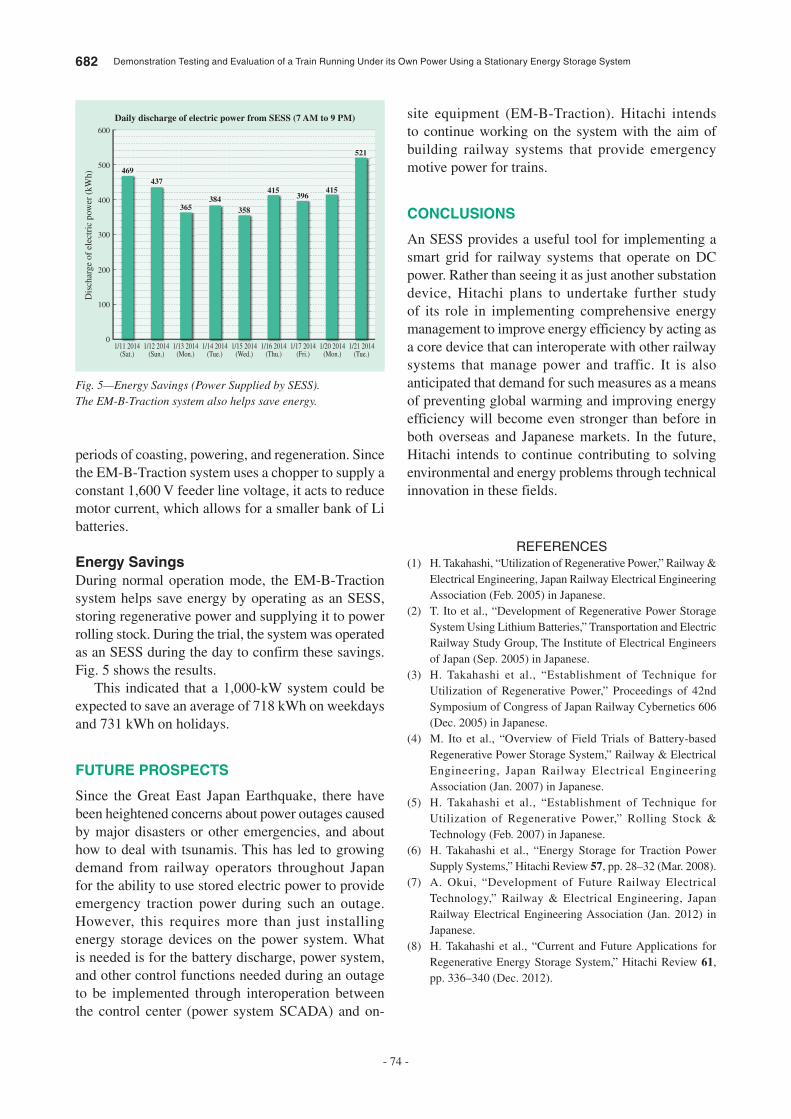
682 Demonstration Testing and Evaluation of a Train Running Under its Own Power Using a Stationary Energy Storage System
- 74 -
site equipment (EM-B-Traction). Hitachi intends
to continue working on the system with the aim of
building railway systems that provide emergency
motive power for trains.
CONCLUSIONS
An SESS provides a useful tool for implementing a
smart grid for railway systems that operate on DC
power. Rather than seeing it as just another substation
device, Hitachi plans to undertake further study
of its role in implementing comprehensive energy
management to improve energy efficiency by acting as
a core device that can interoperate with other railway
systems that manage power and traffic. It is also
anticipated that demand for such measures as a means
of preventing global warming and improving energy
efficiency will become even stronger than before in
both overseas and Japanese markets. In the future,
Hitachi intends to continue contributing to solving
environmental and energy problems through technical
innovation in these fields.
REFERENCES
(1) H. Takahashi, “Utilization of Regenerative Power,” Railway &
Electrical Engineering, Japan Railway Electrical Engineering
Association (Feb. 2005) in Japanese.
(2) T. Ito et al., “Development of Regenerative Power Storage
System Using Lithium Batteries,” Transportation and Electric
Railway Study Group, The Institute of Electrical Engineers
of Japan (Sep. 2005) in Japanese.
(3) H. Takahashi et al., “Establishment of Technique for
Utilization of Regenerative Power,” Proceedings of 42nd
Symposium of Congress of Japan Railway Cybernetics 606
(Dec. 2005) in Japanese.
(4) M. Ito et al., “Overview of Field Trials of Battery-based
Regenerative Power Storage System,” Railway & Electrical
Engineering, Japan Railway Electrical Engineering
Association (Jan. 2007) in Japanese.
(5) H. Takahashi et al., “Establishment of Technique for
Utilization of Regenerative Power,” Rolling Stock &
Technology (Feb. 2007) in Japanese.
(6) H. Takahashi et al., “Energy Storage for Traction Power
Supply Systems,” Hitachi Review 57, pp. 28–32 (Mar. 2008).
(7) A. Okui, “Development of Future Railway Electrical
Technology,” Railway & Electrical Engineering, Japan
Railway Electrical Engineering Association (Jan. 2012) in
Japanese.
(8) H. Takahashi et al., “Current and Future Applications for
Regenerative Energy Storage System,” Hitachi Review 61,
pp. 336–340 (Dec. 2012).
periods of coasting, powering, and regeneration. Since
the EM-B-Traction system uses a chopper to supply a
constant 1,600 V feeder line voltage, it acts to reduce
motor current, which allows for a smaller bank of Li
batteries.
Energy SavingsDuring normal operation mode, the EM-B-Traction
system helps save energy by operating as an SESS,
storing regenerative power and supplying it to power
rolling stock. During the trial, the system was operated
as an SESS during the day to confirm these savings.
Fig. 5 shows the results.
This indicated that a 1,000-kW system could be
expected to save an average of 718 kWh on weekdays
and 731 kWh on holidays.
FUTURE PROSPECTS
Since the Great East Japan Earthquake, there have
been heightened concerns about power outages caused
by major disasters or other emergencies, and about
how to deal with tsunamis. This has led to growing
demand from railway operators throughout Japan
for the ability to use stored electric power to provide
emergency traction power during such an outage.
However, this requires more than just installing
energy storage devices on the power system. What
is needed is for the battery discharge, power system,
and other control functions needed during an outage
to be implemented through interoperation between
the control center (power system SCADA) and on-
600
500
400
469437
365384
358
415396
415
521
300
1/11 2014(Sat.)
1/12 2014(Sun.)
1/13 2014(Mon.)
1/14 2014(Tue.)
1/15 2014(Wed.)
1/16 2014(Thu.)
1/17 2014(Fri.)
1/21 2014(Tue.)
1/20 2014(Mon.)
Dis
char
ge
of
elec
tric
pow
er (
kW
h)
200
100
0
Daily discharge of electric power from SESS (7 AM to 9 PM)
Fig. 5—Energy Savings (Power Supplied by SESS).The EM-B-Traction system also helps save energy.

Hitachi Review Vol. 63 (2014), No. 10 683
- 75 -
Hiroshi Ikarashi
Power Electronics Design Department, Electrical Equipment Information & Control Systems Division, Infrastructure Systems Company, Hitachi, Ltd. He is currently engaged in the design and development of power electronics products.
Akihiro Maoka
Power Supply System Department, Transportation Management & Control Systems Division, Rail Systems Company, Hitachi, Ltd. He is currently engaged in system engineering for railway electrical conversion systems.
Fumiyoshi Kurino
Electrical Facilities Department, Railway Headquarters, Tokyo Metro Co., Ltd. He is currently engaged in the planning of control center systems.
ABOUT THE AUTHORS

684 Hitachi Review Vol. 63 (2014), No. 10
- 76 -
Featured Articles
Preparations for Development of Energy Management
System Integrating Wayside Devices and On-board Systems
—Accuracy Testing of Railway Total Simulator based on Energy-use Analysis
of Okinawa Urban Monorail Line—
Tsutomu Miyauchi
Kazuo Tokuyama
Hirotaka Takahashi
Takashi Kuroshima
OVERVIEW: Hitachi supplies a wide variety of railway subsystem products. As a means of operating these subsystems in tandem to reduce energy consumption, Hitachi is proceeding with the development of energy management systems that integrate the operation of on-board systems with wayside device systems such as the traffic management system, substations, and power management system. As part of this initiative, Hitachi is studying how energy is used across entire railway systems and developing a “railway total simulator” that simulates a railway system to estimate traffic volumes, energy use, and other parameters. Accordingly, Hitachi has undertaken a joint study of energy use with Okinawa Urban Monorail Inc. to evaluate (1) the effect of different rolling stock operating practices on energy consumption, (2) the energy savings achievable by avoiding having more than one train powering at the same time, and (3) the accuracy of the “railway total simulator.”
INTRODUCTION
AWARENESS of environmental problems has been growing around the world in recent years. Although railways are recognized as an energy-efficient mode of transportation that consumes less energy per kilometer for each person carried than alternatives such as cars and airplanes(1), there is a need to achieve even greater energy efficiency in response to environmental problems.
Railway systems are large and complex. In addition to the subsystems associated with train operation, which include the rolling stock that carries passengers, signaling systems that ensure safety, traffic management systems that ensure smooth operation, substations that supply electric power, and power management systems that monitor substations. They also include commercial facilities such as stations and buildings. Since the energy used for train operation accounts for approximately 70% of the total energy consumed by these railway systems, reducing the energy consumption of train operation plays an important role in encouraging energy efficiency(2).
To reduce the amount of energy used for train operation, Hitachi is working on ways of improving the energy efficiency of individual subsystems, and
also developing an energy management system that seeks to save energy by integrating the operation of on-board systems with wayside device systems such as the traffic management system, substations, and power management system. Fig. 1 shows an overview of the energy management system. The aim of the system is to further reduce the amount of energy used to power the trains by collating information from the rolling stock, substations, power management systems, and traffic management systems, and by issuing “suspension of automatic departure route setting,” “coast operation,” and other instructions based on the current system status.
For this purpose we require a highly accurate simulator that can be used to understand how energy is used in the railway system and to study ways of saving energy. Accordingly, Hitachi has collaborated on a study of railway system energy use with Okinawa Urban Monorail Inc., which has been studying how energy is being used and ways of using it efficiently, particularly in relation to train operating practices. The results of this study have also been used to assess the accuracy of the railway total simulator developed by Hitachi to model railway systems and estimate traffic volumes, energy use, and other parameters.
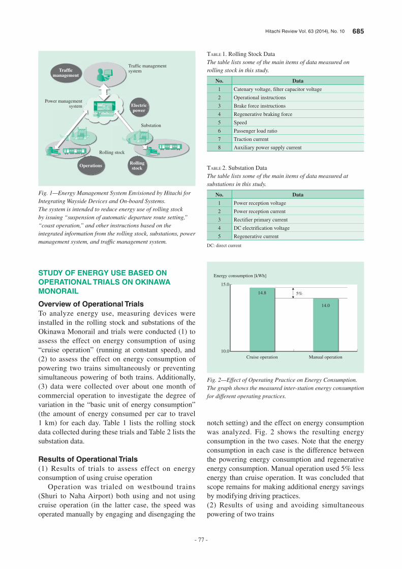
Hitachi Review Vol. 63 (2014), No. 10 685
- 77 -
STUDY OF ENERGY USE BASED ON
OPERATIONAL TRIALS ON OKINAWA
MONORAIL
Overview of Operational Trials
To analyze energy use, measuring devices were installed in the rolling stock and substations of the Okinawa Monorail and trials were conducted (1) to assess the effect on energy consumption of using “cruise operation” (running at constant speed), and (2) to assess the effect on energy consumption of powering two trains simultaneously or preventing simultaneous powering of both trains. Additionally, (3) data were collected over about one month of commercial operation to investigate the degree of variation in the “basic unit of energy consumption” (the amount of energy consumed per car to travel 1 km) for each day. Table 1 lists the rolling stock data collected during these trials and Table 2 lists the substation data.
Results of Operational Trials
(1) Results of trials to assess effect on energy consumption of using cruise operation
Operation was trialed on westbound trains (Shuri to Naha Airport) both using and not using cruise operation (in the latter case, the speed was operated manually by engaging and disengaging the
notch setting) and the effect on energy consumption was analyzed. Fig. 2 shows the resulting energy consumption in the two cases. Note that the energy consumption in each case is the difference between the powering energy consumption and regenerative energy consumption. Manual operation used 5% less energy than cruise operation. It was concluded that scope remains for making additional energy savings by modifying driving practices.(2) Results of using and avoiding simultaneous powering of two trains
Trafficmanagement
Electricpower
Operations Rollingstock
Traffic management system
Power managementsystem
Substation
Rolling stock
Fig. 1—Energy Management System Envisioned by Hitachi for Integrating Wayside Devices and On-board Systems.The system is intended to reduce energy use of rolling stock by issuing “suspension of automatic departure route setting,” “coast operation,” and other instructions based on the integrated information from the rolling stock, substations, power management system, and traffic management system.
No. Data
1 Catenary voltage, filter capacitor voltage
2 Operational instructions
3 Brake force instructions
4 Regenerative braking force
5 Speed
6 Passenger load ratio
7 Traction current
8 Auxiliary power supply current
TABLE 1. Rolling Stock DataThe table lists some of the main items of data measured on rolling stock in this study.
No. Data
1 Power reception voltage
2 Power reception current
3 Rectifier primary current
4 DC electrification voltage
5 Regenerative current
TABLE 2. Substation DataThe table lists some of the main items of data measured at substations in this study.
DC: direct current
Cruise operation
Energy consumption [kWh]
Manual operation
14.8
10.0
15.0
14.0
5%
Fig. 2—Effect of Operating Practice on Energy Consumption.The graph shows the measured inter-station energy consumption for different operating practices.
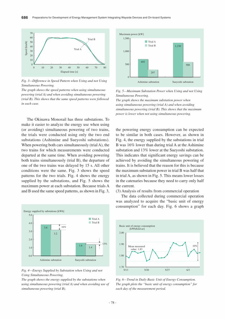
686 Preparations for Development of Energy Management System Integrating Wayside Devices and On-board Systems
- 78 -
The Okinawa Monorail has three substations. To make it easier to analyze the energy use when using (or avoiding) simultaneous powering of two trains, the trials were conducted using only the two end substations (Ashimine and Sueyoshi substations). When powering both cars simultaneously (trial A), the two trains for which measurements were conducted departed at the same time. When avoiding powering both trains simultaneously (trial B), the departure of one of the two trains was delayed by 15 s. All other conditions were the same. Fig. 3 shows the speed patterns for the two trials. Fig. 4 shows the energy supplied by the substations, and Fig. 5 shows the maximum power at each substation. Because trials A and B used the same speed patterns, as shown in Fig. 3,
the powering energy consumption can be expected to be similar in both cases. However, as shown in Fig. 4, the energy supplied by the substations in trial B was 16% lower than during trial A at the Ashimine substation and 13% lower at the Sueyoshi substation. This indicates that significant energy savings can be achieved by avoiding the simultaneous powering of trains. It is believed that the reason for this is because the maximum substation power in trial B was half that in trial A, as shown in Fig. 5. This means lower losses in the catenaries because they need to carry only half the current.(3) Analysis of results from commercial operation
The data collected during commercial operation was analyzed to acquire the “basic unit of energy consumption” for each day. Fig. 6 shows a graph
00
10
20
30
40
50
60
70
10 20 30 40
Elapsed time [s]
Trial A
Trial B
Spee
d [k
m/h
]
50 60 70 80
Fig. 3—Difference in Speed Pattern when Using and not Using Simultaneous Powering.The graph shows the speed patterns when using simultaneous powering (trial A) and when avoiding simultaneous powering (trial B). This shows that the same speed patterns were followed in each case.
Energy supplied by substations [kWh]
Ashimine substation
0.0
1.0
2.0
3.0
4.0
5.0
Sueyoshi substation
Trial ATrial B
16%
3.2
1.61.4
3.8
13%
Fig. 4—Energy Supplied by Substation when Using and not Using Simultaneous Powering.The graph shows the energy supplied by the substations when using simultaneous powering (trial A) and when avoiding use of simultaneous powering (trial B).
Maximum power [kW]
Ashimine substation
1,500
1,000
500
0
Sueyoshi substation
Trial A
Trial B
297
692588
1,330
Fig. 5—Maximum Substation Power when Using and not Using Simultaneous Powering.The graph shows the maximum substation power when using simultaneous powering (trial A) and when avoiding simultaneous powering (trial B). This shows that the maximum power is lower when not using simultaneous powering.
5/13
2.00
Basic unit of energy consumption[kWh/km/car]
1.90
1.80
1.705/20 5/27 6/3
10%Mean measuredvalue: 1.83
Fig. 6—Trend in Daily Basic Unit of Energy Consumption.The graph plots the “basic unit of energy consumption” for each day of the measurement period.

Hitachi Review Vol. 63 (2014), No. 10 687
- 79 -
of this parameter. The results indicate that the value varies from day to day, with a variation range of 10%. It is believed that the differences are due to cases of simultaneous powering and arise from differences between the planned and actual schedules.
OVERVIEW OF HITACHI’S RAILWAY TOTAL
SIMULATOR
As shown in Fig. 7, the railway total simulator consists of models of train operation subsystems such as rolling stock, signaling system, traffic management system, and the electrification system comprising the substations and the power management system. These models are integrated on a common framework. The model of each subsystem is comprised of a number of component models. The electrification system model, for example, has models for direct-current (DC) electrification and alternating-current (AC) electrification [auto transformer (AT) electrification, and booster transformer (BT) electrification]. Similarly, the energy saving equipment modeled for the DC electrification system includes resistor or battery-based devices for absorbing regenerated power and a regeneration inverter (see Fig. 8). The energy saving equipment for the AC electrification system includes a model of a railway static power conditioner (RPC) system (see Fig. 9).
Ways of saving energy on specific lines can be devised by coupling these various models together and by optimizing control systems. Because accurate simulation is important for this work, the development
of the railway total simulator has targeted an accuracy of 5% or better for rolling stock energy consumption.
Traffic management system
Normalschedule
Station A
Speed patternTrain speed
Stop position Location informationSignaling system device
Station BStation CStation DStation E
Schedule
Operationadjustment
Electrification systemSubstation 1 Converter Substation 2
Rectifier 1 Battery 1
Battery 2
Rectifier 2
PRC
Signaling system
Framework
Point
Route
Signalingsystem type
Rolling stock
Limitedexpress train
Rapidtrain
Localtrain 2
Localtrain 1
VVVF3VVVF2VVVF1Chopper
IM3IM2IM1
Converter
Battery
DCM
Interlockingsystem
Track circuitallocation
Fig. 7—Features of Railway Total Simulator.The user can select the required subsystems and equipment to include, which allows the study of any configuration, from individual devices up to the entire system.
PRC: programmed route control DCM: direct current motor IM: induction motor VVVF: variable voltage variable frequency
Battery-baseddevice forabsorbing
regeneratedpower
Resistor-baseddevice forabsorbing
regeneratedpower
Regenerationinverter
Power transmission system
DC electrification
Station
Fig. 8—Resistor- and Battery-based Devices for Absorbing Regenerated Power and Regeneration Inverter.The simulator models devices for absorbing regenerated power with DC electrification to evaluate the consequences of installation.
RPC
Power transmission system
AC electrification
Fig. 9—RPC System for AC Electrification.The simulator models the power distribution systems used with AC electrification to evaluate the consequences of installation.
RPC: railway static power conditioner
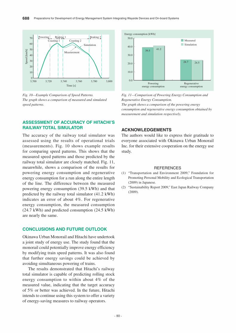
688 Preparations for Development of Energy Management System Integrating Wayside Devices and On-board Systems
- 80 -
ACKNOWLEDGEMENTS
The authors would like to express their gratitude to everyone associated with Okinawa Urban Monorail Inc. for their extensive cooperation on the energy use study.
REFERENCES
(1) “Transportation and Environment 2009,” Foundation for Promoting Personal Mobility and Ecological Transportation (2009) in Japanese.
(2) “Sustainability Report 2009,” East Japan Railway Company (2009).
ASSESSMENT OF ACCURACY OF HITACHI’S
RAILWAY TOTAL SIMULATOR
The accuracy of the railway total simulator was assessed using the results of operational trials (measurements). Fig. 10 shows example results for comparing speed patterns. This shows that the measured speed patterns and those predicted by the railway total simulator are closely matched. Fig. 11, meanwhile, shows a comparison of the results for powering energy consumption and regenerative energy consumption for a run along the entire length of the line. The difference between the measured powering energy consumption (39.5 kWh) and that predicted by the railway total simulator (41.2 kWh) indicates an error of about 4%. For regenerative energy consumption, the measured consumption (24.7 kWh) and predicted consumption (24.5 kWh) are nearly the same.
CONCLUSIONS AND FUTURE OUTLOOK
Okinawa Urban Monorail and Hitachi have undertook a joint study of energy use. The study found that the monorail could potentially improve energy efficiency by modifying train speed patterns. It was also found that further energy savings could be achieved by avoiding simultaneous powering of trains.
The results demonstrated that Hitachi’s railway total simulator is capable of predicting rolling stock energy consumption to within about 4% of the measured value, indicating that the target accuracy of 5% or better was achieved. In the future, Hitachi intends to continue using this system to offer a variety of energy-saving measures to railway operators.
3,7000
10
20
30
40
50
60
70
3,720 3,740 3,760
Time [s]
Spee
d [k
m/h
]
PoweringCoasting 1 Coasting 2
Braking 1 Braking 2
Simulation
Measurement
3,780 3,800
Fig. 10—Example Comparison of Speed Patterns.The graph shows a comparison of measured and simulated speed patterns.
Energy consumption [kWh]
0.0Powering
energy consumptionRegenerative
energy consumption
10.0
20.0
30.0
40.0
50.0Measured
Simulation
41.239.5
24.524.7
Fig. 11—Comparison of Powering Energy Consumption and Regenerative Energy Consumption.The graph shows a comparison of the powering energy consumption and regenerative energy consumption obtained by measurement and simulation respectively.
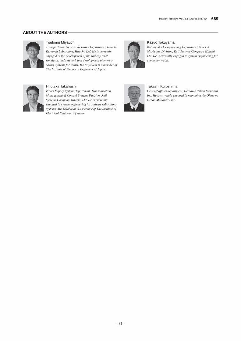
Hitachi Review Vol. 63 (2014), No. 10 689
- 81 -
Kazuo Tokuyama
Rolling Stock Engineering Department, Sales & Marketing Division, Rail Systems Company, Hitachi, Ltd. He is currently engaged in system engineering for commuter trains.
Takashi Kuroshima
General affairs department, Okinawa Urban Monorail Inc. He is currently engaged in managing the Okinawa Urban Monorail Line.
Tsutomu Miyauchi
Transportation Systems Research Department, Hitachi Research Laboratory, Hitachi, Ltd. He is currently engaged in the development of the railway total simulator, and research and development of energy-saving systems for trains. Mr. Miyauchi is a member of The Institute of Electrical Engineers of Japan.
Hirotaka Takahashi
Power Supply System Department, Transportation Management & Control Systems Division, Rail Systems Company, Hitachi, Ltd. He is currently engaged in system engineering for railway substations systems. Mr. Takahashi is a member of The Institute of Electrical Engineers of Japan.
ABOUT THE AUTHORS