raised access floors electrical stations, s witch rooms and server rooms
TRANSCRIPT

Raised Access Floors
Electrical stations, switch rooms and server rooms

Company: Lindner Group | Department: PM Flooring Division | Topic: Product Training Floor Systems | Date: 12.2.2009 | Page: 2
For screwing of panels and stringers
For fixing of the gasket
Fixing of standard stringer
For fixing of the gasket
For fixing of the pedestal bracing
Hole for locking glue
Raised Floor PedestalsHead plate

Company: Lindner Group | Department: PM Flooring Division | Topic: Product Training Floor Systems | Date: 12.2.2009 | Page: 3
Profile dimensions
CL41 x 40 x 1
CM84 x 40 x 1.7
CH126 x 40 x 2
CS41 x 40 x 1.7
Reinforcement profilesOverview
Company: Lindner Group | Department: PM Flooring Division | Topic: Product Training Floor Systems | Date: 12.2.2009 | Page: 4
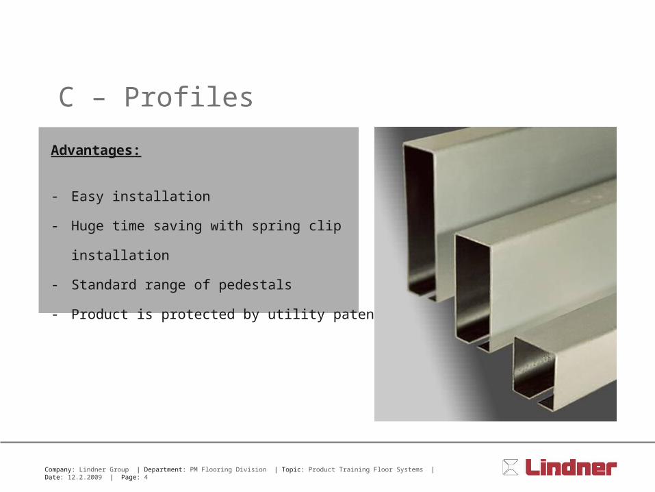
Advantages:
- Easy installation
- Huge time saving with spring clip installation
- Standard range of pedestals
- Product is protected by utility patent
C – Profiles

Company: Lindner Group | Department: PM Flooring Division | Topic: Product Training Floor Systems | Date: 12.2.2009 | Page: 5
Install spring clip from below into the slot
Turn of 90° clockwise
Also with deinstallation!
Variant 1:
High Strength Reinforcement Profiles Fixing

Company: Lindner Group | Department: PM Flooring Division | Topic: Product Training Floor Systems | Date: 12.2.2009 | Page: 6
Variant 2:
Install hammer head screw from below into the slot
Rotate screw 90° and tighten it
High Strength Reinforcement Profiles Fixing

Company: Lindner Group | Department: PM Flooring Division | Topic: Product Training Floor Systems | Date: 12.2.2009 | Page: 7
High Strength Reinforcement Profiles Panel support
Fixing gasket:
Support of the raised floor panels
Fixing gasket with four noppes for
supporting the corners of the panel

Company: Lindner Group | Department: PM Flooring Division | Topic: Product Training Floor Systems | Date: 12.2.2009 | Page: 8
Connection of reinforcement profiles:
Cross connector:
- Connection on the reinforcement profile
with drilling screws
- Connection of the crossing
reinforcement profile with drilling screws
High Strength Reinforcement Profiles Parallel and cross connectors

Company: Lindner Group | Department: PM Flooring Division | Topic: Product Training Floor Systems | Date: 12.2.2009 | Page: 9
Connection of reinforcement profiles:
Parallel connector:
- Connection on the reinforcement profile
with drilling screws
- Connection of the additional
reinforcement profile with drilling screws
High Strength Reinforcement Profiles Parallel and cross connectors

Company: Lindner Group | Department: PM Flooring Division | Topic: Product Training Floor Systems | Date: 12.2.2009 | Page: 10
Reinforcement profiles
Company: Lindner Group | Department: PM Flooring Division | Topic: Product Training Floor Systems | Date: 12.2.2009 | Page: 11
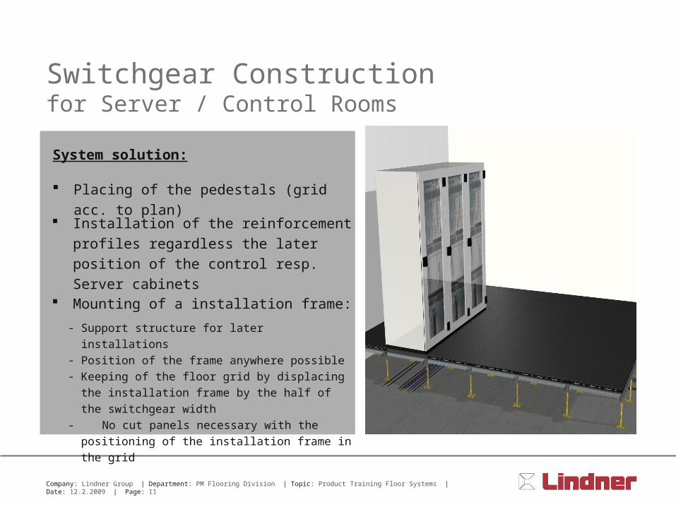
Switchgear Constructionfor Server / Control Rooms
System solution:
Placing of the pedestals (grid acc. to plan)
Installation of the reinforcement profiles
regardless the later position of the control
resp. Server cabinets
Mounting of a installation frame:
- Support structure for later installations- Position of the frame anywhere possible- Keeping of the floor grid by displacing the installation
frame by the half of the switchgear width
- No cut panels necessary with the positioning of the
installation frame in the grid
Installation
frame
Panel
Reinforcement
profile

Company: Lindner Group | Department: PM Flooring Division | Topic: Product Training Floor Systems | Date: 12.2.2009 | Page: 12
Switchgear constructionLater conversion
Flexibility with change of use:
Replacing of switchgear cabinet / server is
easily possible
Replacing of the installations in the panel grid:
- Replacing of the installation frame in a different grid field
- Closing of the previous opening with the panel which
were taken out of the new opening
- Replacing and cabling of the equipment
Company: Lindner Group | Department: PM Flooring Division | Topic: Product Training Floor Systems | Date: 12.2.2009 | Page: 13
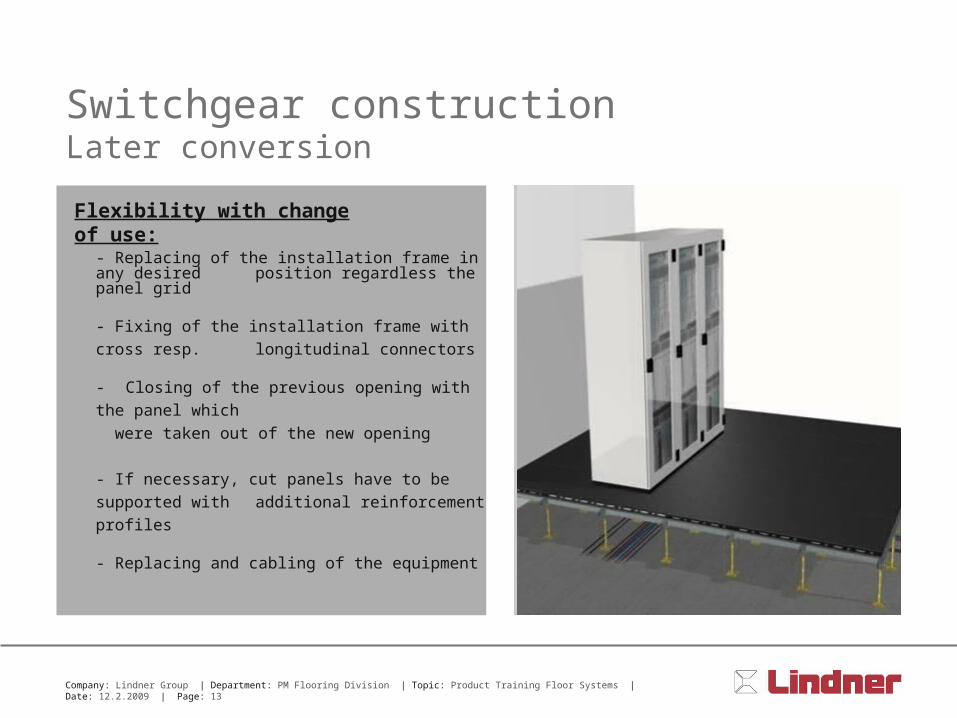
Switchgear constructionLater conversion
Flexibility with change of use:
- Replacing of the installation frame in any desired position regardless the panel grid
- Fixing of the installation frame with cross resp.
longitudinal connectors
- Closing of the previous opening with the panel which
were taken out of the new opening
- If necessary, cut panels have to be supported with
additional reinforcement profiles
- Replacing and cabling of the equipment

Company: Lindner Group | Department: PM Flooring Division | Topic: Product Training Floor Systems | Date: 12.2.2009 | Page: 14
Application area:
- With high loads
- In computer centres or switch rooms
- With high construction heights of the system floors
- With dynamic loads
Switch Room Constructionfor server rooms / switch rooms

Company: Lindner Group | Department: PM Flooring Division | Topic: Product Training Floor Systems | Date: 12.2.2009 | Page: 15
Thank you for your attention!