r&s fsw-k96 ofdm vsa user manual
TRANSCRIPT

R&S®FSW-K96OFDM Vector Signal AnalysisApplicationUser Manual
1179384402Version 01
(;ÝV\2)

This manual applies to the following R&S®FSW models with firmware version 5.00 and later:● R&S®FSW8 (1331.5003K08 / 1312.8000K08)● R&S®FSW13 (1331.5003K13 / 1312.8000K13)● R&S®FSW26 (1331.5003K26 / 1312.8000K26)● R&S®FSW43 (1331.5003K43 / 1312.8000K43)● R&S®FSW50 (1331.5003K50 / 1312.8000K50)● R&S®FSW67 (1331.5003K67 / 1312.8000K67)● R&S®FSW85 (1331.5003K85 / 1312.8000K85)
The following software options are described:● R&S®FSW-K96 (1313.1539.02)
© 2021 Rohde & Schwarz GmbH & Co. KGMühldorfstr. 15, 81671 München, GermanyPhone: +49 89 41 29 - 0Email: [email protected]: www.rohde-schwarz.comSubject to change – data without tolerance limits is not binding.R&S® is a registered trademark of Rohde & Schwarz GmbH & Co. KG.Trade names are trademarks of the owners.
1179.3844.02 | Version 01 | R&S®FSW-K96
Throughout this manual, products from Rohde & Schwarz are indicated without the ® symbol, e.g. R&S®FSW is indicated asR&S FSW.

ContentsR&S®FSW-K96
3User Manual 1179.3844.02 ─ 01
Contents1 Welcome to the OFDM vector signal analysis (VSA) application......5
1.1 Introduction to vector signal analysis........................................................................ 5
1.2 Starting the R&S FSW OFDM VSA application...........................................................6
1.3 Understanding the display information...................................................................... 7
2 OFDM VSA measurement and results..................................................92.1 OFDM VSA parameters.................................................................................................9
2.2 Evaluation methods for OFDM VSA measurements................................................ 11
3 Measurement basics............................................................................293.1 OFDMA......................................................................................................................... 29
3.2 OFDM parameterization..............................................................................................30
3.3 Channel filter............................................................................................................... 36
3.4 OFDM measurement................................................................................................... 37
3.5 Sample rate and maximum usable I/Q bandwidth for RF input.............................. 39
4 Configuring OFDM VSA measurements............................................ 564.1 Configuration overview.............................................................................................. 57
4.2 Signal description....................................................................................................... 58
4.3 Input, output and frontend settings...........................................................................62
4.4 Trigger settings........................................................................................................... 77
4.5 Data acquisition.......................................................................................................... 82
4.6 Sweep settings............................................................................................................ 86
4.7 Burst search................................................................................................................ 87
4.8 Result ranges.............................................................................................................. 88
4.9 Synchronization, demodulation and tracking.......................................................... 88
4.10 Adjusting settings automatically...............................................................................92
5 Creating a configuration file using the wizard.................................. 945.1 Understanding the R&S FSW-K96 Configuration File Wizard display................... 95
5.2 Configuration steps.................................................................................................. 102
5.3 Reference of wizard menu functions...................................................................... 107
5.4 Example: creating a configuration file from an input signal.................................110
6 Analyzing OFDM VSA vector signals............................................... 118

ContentsR&S®FSW-K96
4User Manual 1179.3844.02 ─ 01
6.1 Result configuration................................................................................................. 118
6.2 Table configuration................................................................................................... 120
6.3 Units........................................................................................................................... 121
6.4 Y-scaling.................................................................................................................... 121
6.5 Markers...................................................................................................................... 123
6.6 Trace / data export configuration............................................................................ 128
7 How to perform measurements in the R&S FSW OFDM VSA appli-cation...................................................................................................131
8 Remote commands for the R&S FSW OFDM VSA application...... 1338.1 Introduction............................................................................................................... 133
8.2 Common suffixes...................................................................................................... 138
8.3 Activating the R&S FSW OFDM VSA application...................................................139
8.4 Configuring the R&S FSW OFDM VSA application................................................141
8.5 Performing a measurement......................................................................................179
8.6 Analysis..................................................................................................................... 183
8.7 Configuring the result display................................................................................. 206
8.8 Retrieving results......................................................................................................214
8.9 Status reporting system........................................................................................... 239
8.10 Deprecated commands.............................................................................................242
8.11 Programming examples: OFDM vector signal analysis........................................ 243
Annex.................................................................................................. 247
A Formulae.............................................................................................249A.1 Error vector magnitude (EVM)................................................................................. 249
A.2 I/Q impairments......................................................................................................... 250
List of commands (OFDM VSA)........................................................251
Index....................................................................................................257

Welcome to the OFDM vector signal analysis (VSA) applicationR&S®FSW-K96
5User Manual 1179.3844.02 ─ 01
1 Welcome to the OFDM vector signal analy-sis (VSA) applicationThe R&S FSW OFDM VSA application performs vector and scalar measurements ondigitally modulated OFDM signals. To perform the measurements it converts RF sig-nals into the complex baseband.
The R&S FSW OFDM VSA application features:
● Analysis of non-standard and standard-conform OFDM systems● I/Q-based measurement results such as EVM, constellation diagrams, power spec-
trum
This user manual contains a description of the functionality that the application pro-vides, including remote control operation.
Functions that are not discussed in this manual are the same as in the Spectrum appli-cation and are described in the R&S FSW base unit user manual.
The latest version is available for download at the product homepage http://www.rohde-schwarz.com/product/FSW.
● Introduction to vector signal analysis........................................................................ 5● Starting the R&S FSW OFDM VSA application........................................................ 6● Understanding the display information......................................................................7
1.1 Introduction to vector signal analysis
The goal of vector signal analysis is to determine the quality of the signal that is trans-mitted by the device under test (DUT) by comparing it against an ideal signal. The DUTis usually connected with the analyzer via a cable. The key task of the analyzer is todetermine the ideal signal. Hence, the analyzer aims to reconstruct the ideal signalfrom the measured signal that is transmitted by the DUT. This ideal signal is commonlyreferred to as the reference signal, while the signal from the DUT is called the mea-surement signal.
After extracting the reference signal, the R&S FSW OFDM VSA application comparesthe measurement signal and the reference signal, and the results of this comparisonare displayed.
Example: The most common vector signal analysis measurement is the EVM (Error Vector Mag-nitude) measurement. Here, the complex baseband reference signal is subtracted fromthe complex baseband measurement signal. The magnitude of this error vector repre-sents the EVM value. The EVM has the advantage that it "summarizes" all potentialerrors and distortions in one single value. If the EVM value is low, the signal quality ofthe DUT is high.
Introduction to vector signal analysis

Welcome to the OFDM vector signal analysis (VSA) applicationR&S®FSW-K96
6User Manual 1179.3844.02 ─ 01
Figure 1-1: Simplified schema of vector signal analysis
1.2 Starting the R&S FSW OFDM VSA application
The R&S FSW OFDM VSA application adds a new application to the R&S FSW.
To activate the R&S FSW OFDM VSA application
1. Select the [MODE] key.
A dialog box opens that contains all operating modes and applications currentlyavailable on your R&S FSW.
2. Select the "OFDM VSA" item.
The R&S FSW opens a new measurement channel for the R&S FSW OFDM VSAapplication.
Multiple Measurement Channels and Sequencer Function
When you activate an application, a new measurement channel is created which deter-mines the measurement settings for that application. The same application can be acti-vated with different measurement settings by creating several channels for the sameapplication.
The number of channels that can be configured at the same time depends on the avail-able memory on the instrument.
Only one measurement can be performed at any time, namely the one in the currentlyactive channel. However, in order to perform the configured measurements consecu-tively, a Sequencer function is provided.
If activated, the measurements configured in the currently active channels are per-formed one after the other in the order of the tabs. The currently active measurement isindicated by a symbol in the tab label. The result displays of the individual channels
Starting the R&S FSW OFDM VSA application

Welcome to the OFDM vector signal analysis (VSA) applicationR&S®FSW-K96
7User Manual 1179.3844.02 ─ 01
are updated in the tabs (as well as the "MultiView") as the measurements are per-formed. Sequential operation itself is independent of the currently displayed tab.
For details on the Sequencer function see the R&S FSW User Manual.
1.3 Understanding the display information
The following figure shows a measurement diagram during analyzer operation. All dif-ferent information areas are labeled. They are explained in more detail in the followingsections.
12
3
4
5
6
1 = Channel bar for firmware and measurement settings2+3 = Window title bar with diagram-specific (trace) information4 = Diagram area5 = Diagram footer with diagram-specific information, depending on measurement application6 = Instrument status bar with error messages, progress bar and date/time display
Channel bar information
In the R&S FSW OFDM VSA application, the R&S FSW shows the following settings:
Table 1-1: Information displayed in the channel bar in R&S FSW OFDM VSA application
Label Description
Ref Level Reference level
Att Mechanical and electronic RF attenuation
Input Input type of the signal source
Offset Reference level offset
Freq Center frequency for the RF signal
Capture Time How long data was captured in current sweep
Sample Rate Sample rate
Understanding the display information

Welcome to the OFDM vector signal analysis (VSA) applicationR&S®FSW-K96
8User Manual 1179.3844.02 ─ 01
Label Description
FFT FFT size
CP Length Cyclic prefix length
Res Len Result length
Config Currently loaded configuration file
In addition, the channel bar also displays information on instrument settings that affectthe measurement results even though this is not immediately apparent from the displayof the measured values (e.g. transducer or trigger settings). This information is dis-played only when applicable for the current measurement. For details see theR&S FSW base unit user manual.
Window title bar information
For each diagram, the header provides the following information:
1 2 34
5
Figure 1-2: Window title bar information in R&S FSW OFDM VSA application
1 = Window name2 = Result type3 = Trace color4 = Trace number5 = Trace mode
Diagram area
The diagram area displays the results according to the selected result displays (seeChapter 2.2, "Evaluation methods for OFDM VSA measurements", on page 11).
Diagram footer information
The diagram footer (beneath the diagram) contains the start and stop symbols or timeof the evaluation range.
Status bar information
The software status, errors and warnings and any irregularities in the software are indi-cated in the status bar at the bottom of the R&S FSW window.
Understanding the display information

OFDM VSA measurement and resultsR&S®FSW-K96
9User Manual 1179.3844.02 ─ 01
2 OFDM VSA measurement and resultsAccess: "Overview" > "Display Config"
Or: [MEAS] > "Display Config"
The R&S FSW OFDM VSA application provides various different result displays forOFDM VSA measurements.
● OFDM VSA parameters............................................................................................ 9● Evaluation methods for OFDM VSA measurements............................................... 11
2.1 OFDM VSA parameters
Several signal parameters are determined during vector signal analysis and displayedin the Result Summary.
For details concerning the calculation of individual parameters, see Chapter A, "Formu-lae", on page 249.
Evaluated cells for EVM and MER resultsFor the numerical EVM and MER results described in Table 2-1, only the symbols inthe specified result length are evaluated. The following cells and carriers are ignored:● All "don't care" cells in all carriers● All zero cells in all carriers● All guard carriers, which consist of zero cells or "don't care" cells only● DC carriers, which consist of zero cells only
Note that for the "EVM vs Carrier", "EVM vs Symbol" and "EVM vs Symbol vs Carrier"results, the traces include the zero cells and DC carriers to avoid gaps.
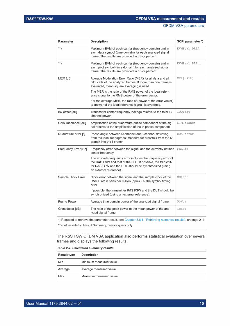
Table 2-1: OFDM VSA parameters
Parameter Description SCPI parameter *)
EVM All [%/dB] Error Vector Magnitude of all pilot and data cells of the ana-lyzed frames
EVM[:ALL]
EVM Data Symbols[%/dB]
Error Vector Magnitude of all data cells of the analyzedframes. All pilot cells are ignored.
EVM:DATA
EVM Pilot Symbols[%/dB]
Error Vector Magnitude of all pilot cells of the analyzedframes. All data cells are ignored.
EVM:PILot
**) Maximum EVM of each carrier (frequency domain) and ineach symbol (time domain) for each analyzed signal frame.The results are provided in dB or percent.
Corresponds to the maximum of the peaks for each frame inthe EVM vs Symbol vs Carrier display.
EVMPeak[:ALL]
*) Required to retrieve the parameter result, see Chapter 8.8.1, "Retrieving numerical results", on page 214
**) not included in Result Summary, remote query only
OFDM VSA parameters
OFDM VSA measurement and resultsR&S®FSW-K96
10User Manual 1179.3844.02 ─ 01
Parameter Description SCPI parameter *)
**) Maximum EVM of each carrier (frequency domain) and ineach data symbol (time domain) for each analyzed signalframe. The results are provided in dB or percent.
EVMPeak:DATA
**) Maximum EVM of each carrier (frequency domain) and ineach pilot symbol (time domain) for each analyzed signalframe. The results are provided in dB or percent.
EVMPeak:PILot
MER [dB] Average Modulation Error Ratio (MER) for all data and allpilot cells of the analyzed frames. If more than one frame isevaluated, mean square averaging is used.
The MER is the ratio of the RMS power of the ideal refer-ence signal to the RMS power of the error vector.
For the average MER, the ratio of (power of the error vector)to (power of the ideal reference signal) is averaged.
MER[:ALL]
I/Q offset [dB] Transmitter center frequency leakage relative to the total Txchannel power
IQOFset
Gain imbalance [dB] Amplification of the quadrature phase component of the sig-nal relative to the amplification of the in-phase component
GIMBalance
Quadrature error [°] Phase angle between Q-channel and I-channel deviatingfrom the ideal 90 degrees; measure for crosstalk from the Q-branch into the I-branch
QUADerror
Frequency Error [Hz] Frequency error between the signal and the currently definedcenter frequency
The absolute frequency error includes the frequency error ofthe R&S FSW and that of the DUT. If possible, the transmit-ter R&S FSW and the DUT should be synchronized (usingan external reference).
FERRor
Sample Clock Error Clock error between the signal and the sample clock of theR&S FSW in parts per million (ppm), i.e. the symbol timingerror
If possible, the transmitter R&S FSW and the DUT should besynchronized (using an external reference).
SERRor
Frame Power Average time domain power of the analyzed signal frame POWer
Crest factor [dB] The ratio of the peak power to the mean power of the ana-lyzed signal frame
CRESt
*) Required to retrieve the parameter result, see Chapter 8.8.1, "Retrieving numerical results", on page 214
**) not included in Result Summary, remote query only
The R&S FSW OFDM VSA application also performs statistical evaluation over severalframes and displays the following results:Table 2-2: Calculated summary results
Result type Description
Min Minimum measured value
Average Average measured value
Max Maximum measured value
OFDM VSA parameters

OFDM VSA measurement and resultsR&S®FSW-K96
11User Manual 1179.3844.02 ─ 01
2.2 Evaluation methods for OFDM VSA measurements
The data that was measured by the R&S FSW can be evaluated using various differentmethods without having to start a new measurement. Which results are displayeddepends on the selected evaluation.
The R&S FSW OFDM VSA application provides the following evaluation methods:
Allocation Matrix............................................................................................................ 11Bitstream....................................................................................................................... 12CCDF............................................................................................................................ 14Channel Flatness.......................................................................................................... 14Constellation Diagram...................................................................................................15Constellation vs Carrier.................................................................................................16Constellation vs Symbol................................................................................................17EVM vs Carrier..............................................................................................................18Constellation vs Symbol................................................................................................18EVM vs Symbol vs Carrier............................................................................................ 19Group Delay.................................................................................................................. 20Impulse Response........................................................................................................ 20Magnitude Capture........................................................................................................21Marker Table................................................................................................................. 22Notes.............................................................................................................................22Power Spectrum............................................................................................................22Power vs Carrier........................................................................................................... 23Power vs Symbol.......................................................................................................... 24Power vs Symbol vs Carrier..........................................................................................25Result Summary............................................................................................................26Signal Flow....................................................................................................................27Trigger to Sync..............................................................................................................27
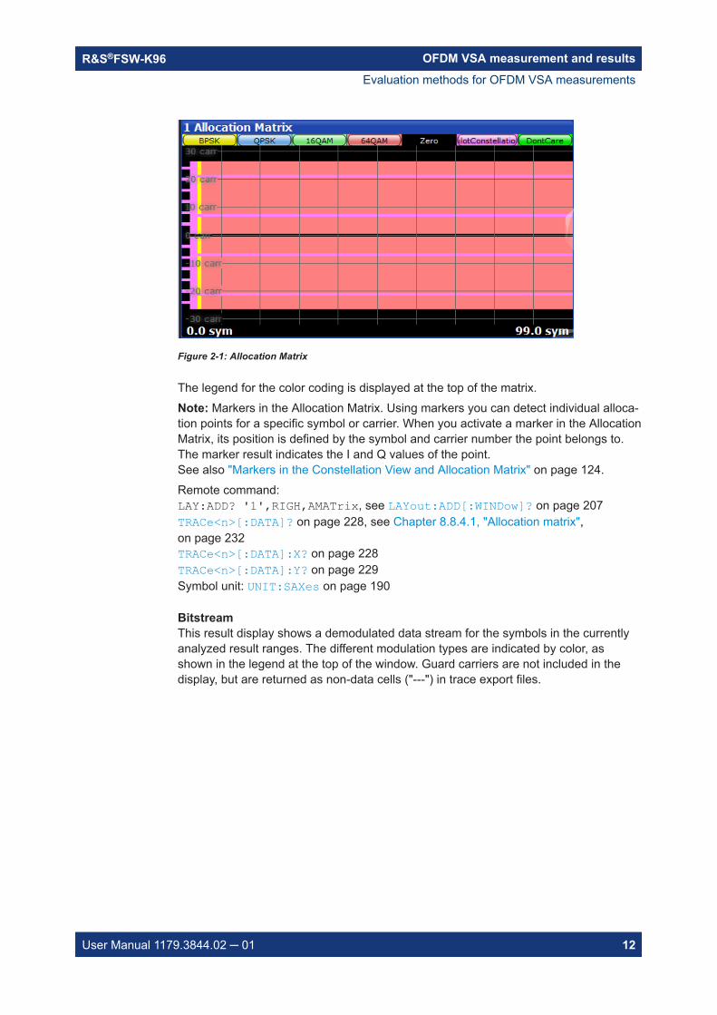
Allocation MatrixThe Allocation Matrix display is a graphical representation of the OFDM cell structuredefined in the currently loaded configuration file.Use markers to get more detailed information on the individual cells.
Evaluation methods for OFDM VSA measurements
OFDM VSA measurement and resultsR&S®FSW-K96
12User Manual 1179.3844.02 ─ 01
Figure 2-1: Allocation Matrix
The legend for the color coding is displayed at the top of the matrix.Note: Markers in the Allocation Matrix. Using markers you can detect individual alloca-tion points for a specific symbol or carrier. When you activate a marker in the AllocationMatrix, its position is defined by the symbol and carrier number the point belongs to.The marker result indicates the I and Q values of the point.See also "Markers in the Constellation View and Allocation Matrix" on page 124.Remote command: LAY:ADD? '1',RIGH,AMATrix, see LAYout:ADD[:WINDow]? on page 207TRACe<n>[:DATA]? on page 228, see Chapter 8.8.4.1, "Allocation matrix",on page 232TRACe<n>[:DATA]:X? on page 228TRACe<n>[:DATA]:Y? on page 229Symbol unit: UNIT:SAXes on page 190
BitstreamThis result display shows a demodulated data stream for the symbols in the currentlyanalyzed result ranges. The different modulation types are indicated by color, asshown in the legend at the top of the window. Guard carriers are not included in thedisplay, but are returned as non-data cells ("---") in trace export files.
Evaluation methods for OFDM VSA measurements

OFDM VSA measurement and resultsR&S®FSW-K96
13User Manual 1179.3844.02 ─ 01
The bitstream is derived from the order of the constellation points in the configurationfile.
Example: For QPSK, the value that is in the first position defines "00", the value that is in the sec-ond position defines "01", the value that is in the third position "10" and the last value"11".
Figure 2-2: Extract from configuration file defining the constellation points
Remote command: LAY:ADD? '1',RIGH,BITS, see LAYout:ADD[:WINDow]? on page 207TRACe:DATA?, see Chapter 8.8.4.2, "Bitstream", on page 233
Evaluation methods for OFDM VSA measurements

OFDM VSA measurement and resultsR&S®FSW-K96
14User Manual 1179.3844.02 ─ 01
CCDFThe CCDF results display shows the probability of an amplitude exceeding the meanpower. The x-axis displays power relative to the measured mean power.
Figure 2-3: CCDF display
Remote command: LAY:ADD? '1',RIGH,CCDF, see LAYout:ADD[:WINDow]? on page 207TRACe:DATA?, see Chapter 8.8.4.3, "CCDF", on page 233TRACe<n>[:DATA]:X? on page 228
Channel FlatnessThe Channel Flatness display shows the amplitude of the channel transfer function vs.carrier.The statistic is performed over all analyzed frames.
Evaluation methods for OFDM VSA measurements

OFDM VSA measurement and resultsR&S®FSW-K96
15User Manual 1179.3844.02 ─ 01
Figure 2-4: Channel Flatness Display
Remote command: LAY:ADD? '1',RIGH,CHFL, see LAYout:ADD[:WINDow]? on page 207TRACe:DATA?, see Chapter 8.8.4.4, "Channel flatness", on page 233TRACe<n>[:DATA]:X? on page 228Carrier unit: UNIT:CAXes on page 189
Constellation DiagramThe Constellation Diagram shows the inphase and quadrature results for the analyzedinput data. The ideal points for the selected cell types are displayed for reference pur-poses.
Figure 2-5: Constellation diagram
Evaluation methods for OFDM VSA measurements

OFDM VSA measurement and resultsR&S®FSW-K96
16User Manual 1179.3844.02 ─ 01
The legend for the color coding is displayed at the top of the matrix. If you click on oneof the codes, only the selected constellation points are displayed. Click again, and allconstellation points are displayed again (according to the constellation filter).See Chapter 6.1, "Result configuration", on page 118.Note: Markers in the Constellation diagram. Using markers you can detect individualconstellation points for a specific symbol or carrier. When you activate a marker in theConstellation diagram, its position is defined by the symbol and carrier number thepoint belongs to. The marker result indicates the I and Q values of the point.
Figure 2-6: Marker in a Constellation diagram
See also "Markers in the Constellation View and Allocation Matrix" on page 124.Remote command: LAY:ADD? '1',RIGH,CONS, see LAYout:ADD[:WINDow]? on page 207TRACe:DATA?, see Chapter 8.8.4.5, "Constellation diagram", on page 233Marker I/Q values:CALCulate<n>:MARKer<m>:Z on page 224
Constellation vs CarrierThe Constellation vs. Carrier display shows the inphase and quadrature magnituderesults of all analyzed symbols over the corresponding carriers. The inphase valuesare displayed as yellow dots; the quadrature-values are displayed as blue dots.
Evaluation methods for OFDM VSA measurements

OFDM VSA measurement and resultsR&S®FSW-K96
17User Manual 1179.3844.02 ─ 01
Figure 2-7: Constellation vs Carrier display
Note: This result display is only available if synchronization is successful.Remote command: LAY:ADD? '1',RIGH,CCAR, see LAYout:ADD[:WINDow]? on page 207TRACe:DATA?, see Chapter 8.8.4, "Using the TRACe[:DATA] command", on page 231Carrier unit: UNIT:CAXes on page 189Symbol selection for marker: CALCulate<n>:MARKer<m>:Z on page 224
Constellation vs SymbolThe Constellation vs. Symbol display shows the inphase and quadrature magnituderesults of all analyzed carriers over the corresponding symbols. The inphase valuesare displayed as yellow dots; the quadrature-values are displayed as blue dots.
Figure 2-8: Constellation vs Symbol display
Note: This result display is only available if synchronization is successful.
Evaluation methods for OFDM VSA measurements

OFDM VSA measurement and resultsR&S®FSW-K96
18User Manual 1179.3844.02 ─ 01
Remote command: LAY:ADD? '1',RIGH,CSYM, see LAYout:ADD[:WINDow]? on page 207TRACe:DATA?, see Chapter 8.8.4, "Using the TRACe[:DATA] command", on page 231Symbol unit: UNIT:SAXes on page 190Carrier selection for marker: CALCulate<n>:MARKer<m>:Z on page 224
EVM vs CarrierThe EVM vs Carrier display shows the EVM of each carrier of the analyzed signalframe in the frequency domain. The results are provided in dB. Multiple traces displaystatistical evaluations over carriers.
Figure 2-9: EVM vs Carrier display
Note: This result display is only available if synchronization is successful.Guard carriers to the left and right of the spectrum are not included in the EVM calcula-tion. However, zero cells and the DC carrier are included.Remote command: LAY:ADD? '1',RIGH,EVC, see LAYout:ADD[:WINDow]? on page 207TRACe:DATA?, see Chapter 8.8.4.8, "EVM vs carrier", on page 236TRACe<n>[:DATA]:X? on page 228Carrier unit: UNIT:CAXes on page 189EVM unit: UNIT:EVM on page 189
Constellation vs SymbolThe Constellation vs. Symbol display shows the inphase and quadrature magnituderesults of all analyzed carriers over the corresponding symbols. The inphase valuesare displayed as yellow dots; the quadrature-values are displayed as blue dots.
Evaluation methods for OFDM VSA measurements

OFDM VSA measurement and resultsR&S®FSW-K96
19User Manual 1179.3844.02 ─ 01
Figure 2-10: Constellation vs Symbol display
Note: This result display is only available if synchronization is successful.Remote command: LAY:ADD? '1',RIGH,CSYM, see LAYout:ADD[:WINDow]? on page 207TRACe:DATA?, see Chapter 8.8.4, "Using the TRACe[:DATA] command", on page 231Symbol unit: UNIT:SAXes on page 190Carrier selection for marker: CALCulate<n>:MARKer<m>:Z on page 224
EVM vs Symbol vs CarrierThe EVM vs Symbol vs Carrier display shows the EVM of each carrier (frequencydomain) and in each symbol (time domain) of the analyzed signal frame.The results are provided in dB or percent, depending on the unit settings.
Figure 2-11: EVM vs Symbol vs Carrier display
Evaluation methods for OFDM VSA measurements
OFDM VSA measurement and resultsR&S®FSW-K96
20User Manual 1179.3844.02 ─ 01
The EVM values are represented by colors. The corresponding color map is displayedat the top of the result display.Note: This result display is only available if synchronization is successful.Remote command: LAY:ADD? '1',RIGH,EVSC, see LAYout:ADD[:WINDow]? on page 207TRACe:DATA?, see Chapter 8.8.4.10, "EVM vs symbol vs carrier", on page 236TRACe<n>[:DATA]:X? on page 228TRACe<n>[:DATA]:Y? on page 229Carrier unit: UNIT:CAXes on page 189Symbol unit: UNIT:SAXes on page 190EVM unit: UNIT:EVM on page 189Carrier selection for marker: CALCulate<n>:MARKer<m>:Z on page 224
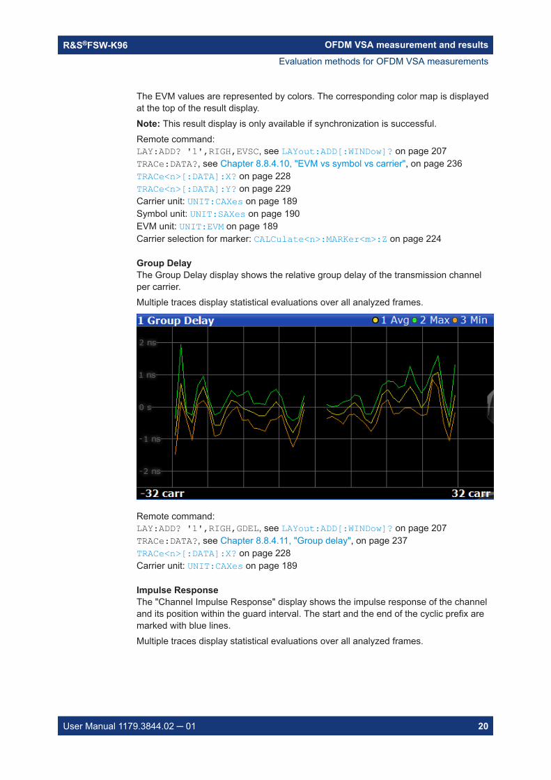
Group DelayThe Group Delay display shows the relative group delay of the transmission channelper carrier.Multiple traces display statistical evaluations over all analyzed frames.
Remote command: LAY:ADD? '1',RIGH,GDEL, see LAYout:ADD[:WINDow]? on page 207TRACe:DATA?, see Chapter 8.8.4.11, "Group delay", on page 237TRACe<n>[:DATA]:X? on page 228Carrier unit: UNIT:CAXes on page 189
Impulse ResponseThe "Channel Impulse Response" display shows the impulse response of the channeland its position within the guard interval. The start and the end of the cyclic prefix aremarked with blue lines.Multiple traces display statistical evaluations over all analyzed frames.
Evaluation methods for OFDM VSA measurements

OFDM VSA measurement and resultsR&S®FSW-K96
21User Manual 1179.3844.02 ─ 01
Figure 2-12: Channel Impulse Response Display
Remote command: LAY:ADD? '1',RIGH,IRES, see LAYout:ADD[:WINDow]? on page 207TRACe:DATA?, see Chapter 8.8.4.12, "Impulse response", on page 237TRACe<n>[:DATA]:X? on page 228Linear/ logarithmic scaling: UNIT:IRESponse on page 190
Magnitude CaptureThe capture buffer contains the complete range of captured data for the last sweep.The "Magnitude Capture" display shows the power of the captured I/Q data in dBmversus time. The analyzed frames are identified with a green bar at the bottom of the"Magnitude Capture" display.
Figure 2-13: Magnitude Capture display
Evaluation methods for OFDM VSA measurements
OFDM VSA measurement and resultsR&S®FSW-K96
22User Manual 1179.3844.02 ─ 01
Remote command: LAY:ADD? '1',RIGH,MCAP, see LAYout:ADD[:WINDow]? on page 207TRACe:DATA?, see Chapter 8.8.4.13, "Magnitude capture", on page 237TRACe<n>[:DATA]:X? on page 228Time unit: UNIT:TAXes on page 191
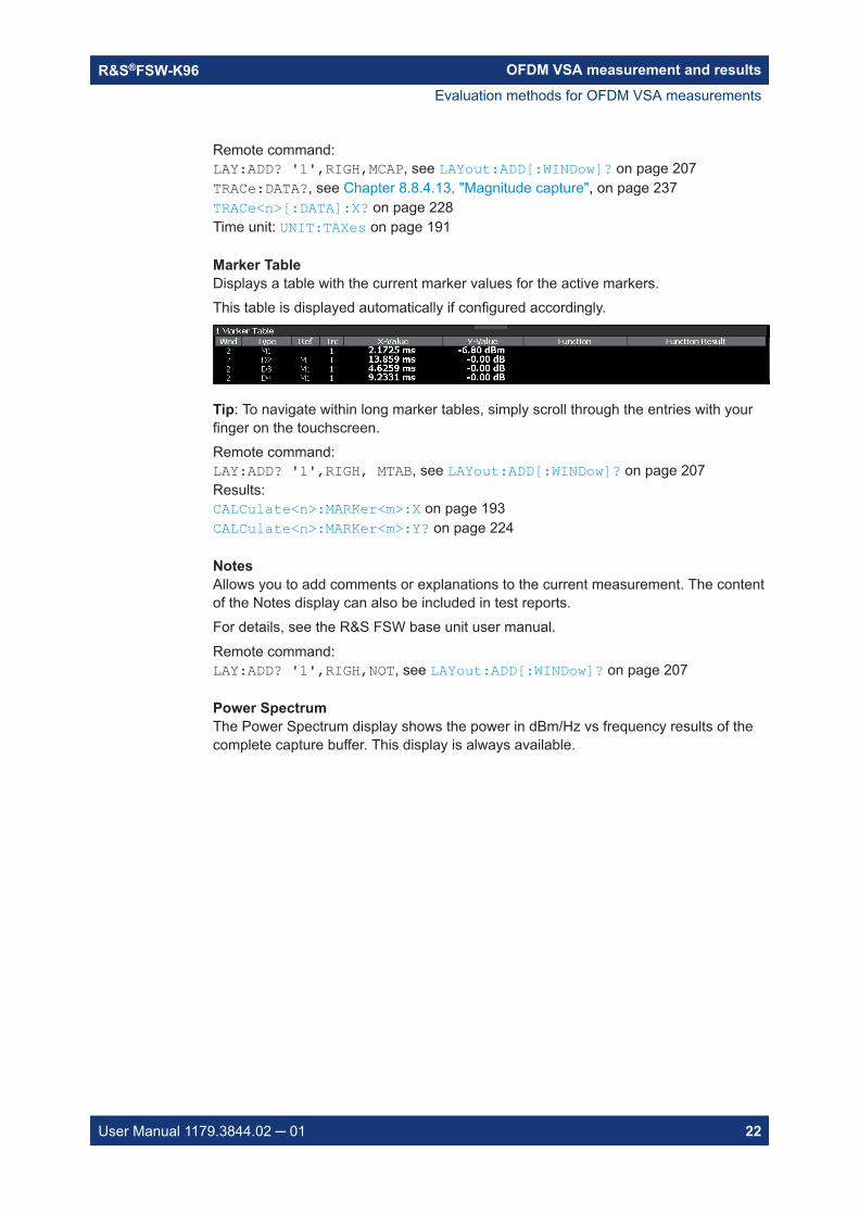
Marker TableDisplays a table with the current marker values for the active markers.This table is displayed automatically if configured accordingly.
Tip: To navigate within long marker tables, simply scroll through the entries with yourfinger on the touchscreen.Remote command: LAY:ADD? '1',RIGH, MTAB, see LAYout:ADD[:WINDow]? on page 207Results:CALCulate<n>:MARKer<m>:X on page 193CALCulate<n>:MARKer<m>:Y? on page 224
NotesAllows you to add comments or explanations to the current measurement. The contentof the Notes display can also be included in test reports.For details, see the R&S FSW base unit user manual.Remote command: LAY:ADD? '1',RIGH,NOT, see LAYout:ADD[:WINDow]? on page 207
Power SpectrumThe Power Spectrum display shows the power in dBm/Hz vs frequency results of thecomplete capture buffer. This display is always available.
Evaluation methods for OFDM VSA measurements

OFDM VSA measurement and resultsR&S®FSW-K96
23User Manual 1179.3844.02 ─ 01
Figure 2-14: Power Spectrum display
The usable I/Q bandwidth is indicated for reference. If a channel filter is active, the 6-dB-bandwidth of the filter is indicated instead.See "6-dB Bandwidth" on page 85.
Figure 2-15: Power spectrum with active channel filter
Remote command: LAY:ADD? '1',RIGH,PSP, see LAYout:ADD[:WINDow]? on page 207TRACe:DATA?, see Chapter 8.8.4.17, "Power spectrum", on page 239Frequency unit: UNIT:FAXes on page 190
Power vs CarrierThe Power vs. Carrier display shows the power of all OFDM symbols in the analyzedsignal frames for each carrier. The power is measured with a resolution bandwidthequal to the carrier spacing.Multiple traces display statistical evaluations over all analyzed frames.
Evaluation methods for OFDM VSA measurements

OFDM VSA measurement and resultsR&S®FSW-K96
24User Manual 1179.3844.02 ─ 01
Figure 2-16: Power vs Carrier display
Note: This result display is only available if synchronization is successful.Remote command: LAY:ADD? '1',RIGH,PCAR, see LAYout:ADD[:WINDow]? on page 207TRACe:DATA?, see Chapter 8.8.4.14, "Power vs carrier", on page 238TRACe<n>[:DATA]:X? on page 228Carrier unit: UNIT:CAXes on page 189
Power vs SymbolThe Power vs Symbol display shows the power of all OFDM carriers in the analyzedsignal frames for each symbol. The power is measured with a resolution bandwidthequal to the carrier spacing. Carriers which contain 'Zero'-cells over the complete sym-bol range (e.g. guard carriers or DC carrier) are excluded.Multiple traces display statistical evaluations over all analyzed frames.Vertical blue lines indicate the borders between frames.
Evaluation methods for OFDM VSA measurements

OFDM VSA measurement and resultsR&S®FSW-K96
25User Manual 1179.3844.02 ─ 01
Figure 2-17: Power vs Symbol display
Note: This result display is only available if synchronization is successful.Remote command: LAY:ADD? '1',RIGH,PSYM, see LAYout:ADD[:WINDow]? on page 207TRACe:DATA?, see Chapter 8.8.4.15, "Power vs symbol", on page 238TRACe<n>[:DATA]:X? on page 228Symbol unit: UNIT:SAXes on page 190
Power vs Symbol vs CarrierThe Power vs Carrier vs Symbol display shows the power of each carrier (= frequencydomain) in each symbol (= time domain) of the analyzed signal frames in dBm. Thepower is measured with a resolution bandwidth that equals the carrier spacing.
Figure 2-18: Power vs Symbol vs Carrier display
Evaluation methods for OFDM VSA measurements

OFDM VSA measurement and resultsR&S®FSW-K96
26User Manual 1179.3844.02 ─ 01
The power levels are represented by colors. The corresponding color map is displayedat the top of the result display.Note: This result display is only available if synchronization is successful.Remote command: LAY:ADD? '1',RIGH,PSC, see LAYout:ADD[:WINDow]? on page 207TRACe:DATA?, see Chapter 8.8.4.16, "Power vs symbol vs carrier", on page 238TRACe<n>[:DATA]:X? on page 228TRACe<n>[:DATA]:Y? on page 229Carrier unit: UNIT:CAXes on page 189Symbol unit: UNIT:SAXes on page 190Carrier selection for marker: CALCulate<n>:MARKer<m>:Z on page 224
Result SummaryThe Result Summary table provides numerical measurement results.Statistical evaluation is performed over all analyzed frames within the capture buffer.
Figure 2-19: Result Summary display
Note: If only one frame is available for analysis, the minimum and maximum valuesare not displayed, as they are identical to the average value.For details on the individual results, see Chapter 2.1, "OFDM VSA parameters",on page 9.
Evaluation methods for OFDM VSA measurements

OFDM VSA measurement and resultsR&S®FSW-K96
27User Manual 1179.3844.02 ─ 01
Remote command: LAY:ADD? '1',RIGH,RSUM, see LAYout:ADD[:WINDow]? on page 207Results:FETCh:SUMMary[:ALL]? on page 216
Signal FlowThe Signal Flow display shows a detailed description of the current measurement sta-tus. If demodulation is not successful, it provides useful hints on possible reasons.Unused blocks are shown in gray.
Figure 2-20: Signal Flow display
For the synchronization blocks, a colored bar provides information about the reliabilityof the synchronization result. If the level in the bar falls below the thresholds indicatedby the horizontal line, the color of the bar changes from green to yellow and finally tored. If the synchronization of the block fails, all succeeding arrows change their color,too.For detailed information about the complete synchronization process, refer to Chap-ter 3.4.1, "Synchronization block", on page 37.Remote command: LAY:ADD? '1',RIGH,SFL, see LAYout:ADD[:WINDow]? on page 207Retrieving results:Chapter 8.8.2, "Retrieving signal flow results", on page 218
Trigger to SyncIndicates the time offset between the trigger event and the start of the first OFDMframe. One value per capture is displayed.
Figure 2-21: Trigger to Sync display
Evaluation methods for OFDM VSA measurements

OFDM VSA measurement and resultsR&S®FSW-K96
28User Manual 1179.3844.02 ─ 01
Remote command: LAY:ADD? '1',RIGH,TRIG, see LAYout:ADD[:WINDow]? on page 207Retrieving results:FETCh:TTFRame? on page 218
Evaluation methods for OFDM VSA measurements

Measurement basicsR&S®FSW-K96
29User Manual 1179.3844.02 ─ 01
3 Measurement basicsSome background knowledge on basic terms and principles used in OFDM vector sig-nal analysis is provided here for a better understanding of the required configurationsettings.
● OFDMA................................................................................................................... 29● OFDM parameterization..........................................................................................30● Channel filter...........................................................................................................36● OFDM measurement...............................................................................................37● Sample rate and maximum usable I/Q bandwidth for RF input...............................39
3.1 OFDMA
In an OFDM system, the available spectrum is divided into multiple carriers, called sub-carriers, which are orthogonal to each other. Each of these subcarriers is independ-ently modulated by a low rate data stream.
OFDM is used as well in WLAN, WiMAX and broadcast technologies like DVB. OFDMhas several benefits including its robustness against multipath fading and its efficientreceiver architecture.
Figure 3-1 shows a representation of an OFDM signal taken from 3GPP TR 25.892.Data symbols are independently modulated and transmitted over a high number ofclosely spaced orthogonal subcarriers. In the OFDM-VSA common modulationschemes as QPSK, 16QAM, and 64QAM can be defined as well as arbitrary distrib-uted constellation points.
In the time domain, a guard interval can be added to each symbol to combat inter-OFDM-symbol-interference due to channel delay spread. In EUTRA, the guard intervalis a cyclic prefix which is inserted prior to each OFDM symbol.
Figure 3-1: Frequency-time representation of an OFDM signal
In practice, the OFDM signal can be generated using the inverse fast Fourier transform(IFFT) digital signal processing. The IFFT converts a number N of complex data sym-
OFDMA

Measurement basicsR&S®FSW-K96
30User Manual 1179.3844.02 ─ 01
bols used as frequency domain bins into the time domain signal. Such an N-point IFFTis illustrated in Figure 3-2, where a(mN+n) refers to the nth subchannel modulated datasymbol, during the time period mTu < t ≤ (m+1)Tu.
Figure 3-2: OFDM useful symbol generation using an IFFT
The vector sm is defined as the useful OFDM symbol. It is the time superposition of theN narrowband modulated subcarriers. Therefore, from a parallel stream of N sourcesof data, each one independently modulated, a waveform composed of N orthogonalsubcarriers is obtained. Each subcarrier has the shape of a frequency sinc function(see Figure 3-1).
Figure 3-3 illustrates the mapping from a serial stream of QAM symbols to N parallelstreams, used as frequency domain bins for the IFFT. The N-point time domain blocksobtained from the IFFT are then serialized to create a time domain signal. Not shownin Figure 3-3 is the process of cyclic prefix insertion.
Figure 3-3: OFDM signal generation chain
3.2 OFDM parameterization
A generic OFDM analyzer supports various OFDM standards. Therefore a commonparameterization of OFDM systems has to be defined.
● Time domain description......................................................................................... 30● Frequency domain description................................................................................31● Preamble description.............................................................................................. 35
3.2.1 Time domain description
The fundamental unit of an OFDM signal in the time domain is a sample.
OFDM parameterization

Measurement basicsR&S®FSW-K96
31User Manual 1179.3844.02 ─ 01
An OFDM symbol with a length of NS samples consists of:● A guard interval of length NG
● An FFT interval of length NFFT
NG NFFT
NS
Figure 3-4: OFDM symbol in time domain
3.2.2 Frequency domain description
The FFT intervals of the OFDM symbols are transformed into the frequency domainusing a discrete Fourier transformation. The successive symbols of the OFDM signalare displayed in time-frequency matrices. The fundamental unit of an OFDM signal inthe frequency domain is a cell.
The total area of a time-frequency matrix is called frame. A frame is the highest levelunit used in OFDM VSA.
Figure 3-5: Time-Frequency matrix
Carriers
A column of cells at the same frequency is called carrier.
The carrier number is the column index of a time-frequency matrix. The number '0' isassigned to the DC-carrier, which lies at the transmitter center frequency. The total
OFDM parameterization
Measurement basicsR&S®FSW-K96
32User Manual 1179.3844.02 ─ 01
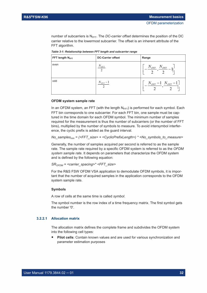
number of subcarriers is NFFT. The DC-carrier offset determines the position of the DCcarrier relative to the lowermost subcarrier. The offset is an inherent attribute of theFFT algorithm.Table 3-1: Relationship between FFT length and subcarrier range
FFT length NFFT DC-Carrier offset Range
even 2FFTN
1
2,
2FFTFFT NN
odd 12
FFTN
21,
21 FFTFFT NN
OFDM system sample rate
In an OFDM system, an FFT (with the length NFFT) is performed for each symbol. EachFFT bin corresponds to one subcarrier. For each FFT bin, one sample must be cap-tured in the time domain for each OFDM symbol. The minimum number of samplesrequired for the measurement is thus the number of subcarriers (or the number of FFTbins), multiplied by the number of symbols to measure. To avoid intersymbol interfer-ence, the cyclic prefix is added as the guard interval.
No_samplesmin = (<FFT_size> + <CyclicPrefixLength>) * <No_symbols_to_measure>
Generally, the number of samples acquired per second is referred to as the samplerate. The sample rate required by a specific OFDM system is referred to as the OFDMsystem sample rate. It depends on parameters that characterize the OFDM systemand is defined by the following equation:
SROFDM = <carrier_spacing>* <FFT_size>
For the R&S FSW OFDM VSA application to demodulate OFDM symbols, it is impor-tant that the number of acquired samples in the application corresponds to the OFDMsystem sample rate.
Symbols
A row of cells at the same time is called symbol.
The symbol number is the row index of a time frequency matrix. The first symbol getsthe number '0'.
3.2.2.1 Allocation matrix
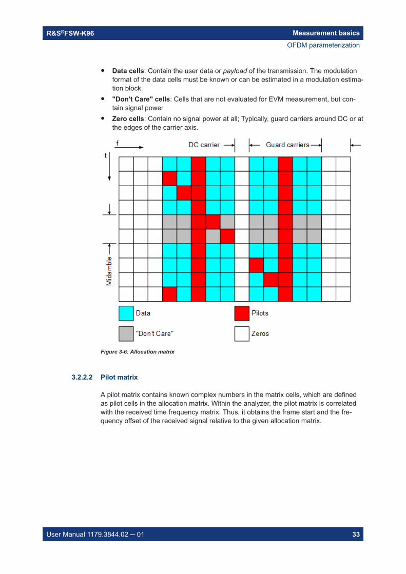
The allocation matrix defines the complete frame and subdivides the OFDM systeminto the following cell types:● Pilot cells: Contain known values and are used for various synchronization and
parameter estimation purposes
OFDM parameterization
Measurement basicsR&S®FSW-K96
33User Manual 1179.3844.02 ─ 01
● Data cells: Contain the user data or payload of the transmission. The modulationformat of the data cells must be known or can be estimated in a modulation estima-tion block.
● "Don't Care" cells: Cells that are not evaluated for EVM measurement, but con-tain signal power
● Zero cells: Contain no signal power at all; Typically, guard carriers around DC or atthe edges of the carrier axis.
Figure 3-6: Allocation matrix
3.2.2.2 Pilot matrix
A pilot matrix contains known complex numbers in the matrix cells, which are definedas pilot cells in the allocation matrix. Within the analyzer, the pilot matrix is correlatedwith the received time frequency matrix. Thus, it obtains the frame start and the fre-quency offset of the received signal relative to the given allocation matrix.
OFDM parameterization

Measurement basicsR&S®FSW-K96
34User Manual 1179.3844.02 ─ 01
Figure 3-7: Pilot matrix
3.2.2.3 Constellation vector
A constellation vector contains all possible numbers in the complex plane that belongto a specific modulation format. Constellation vectors must be defined for each possi-ble data modulation format. The magnitude within the constellation vectors must bescaled according to the pilot matrix. One entry in the constellation vector is called con-stellation point'.
Differential modulation is not supported. The respective absolute modulation schememust be used instead (e.g. QPSK instead of DQPSK). Periodically rotated constella-tions are not supported. The set union of all constellations must be used instead (e.g.8PSK instead of PI/4-DQPSK).
21
21 j
21
21 j
21
21 j
21
21 j
Constellation Point
Figure 3-8: QPSK constellation vector
3.2.2.4 Modulation matrix
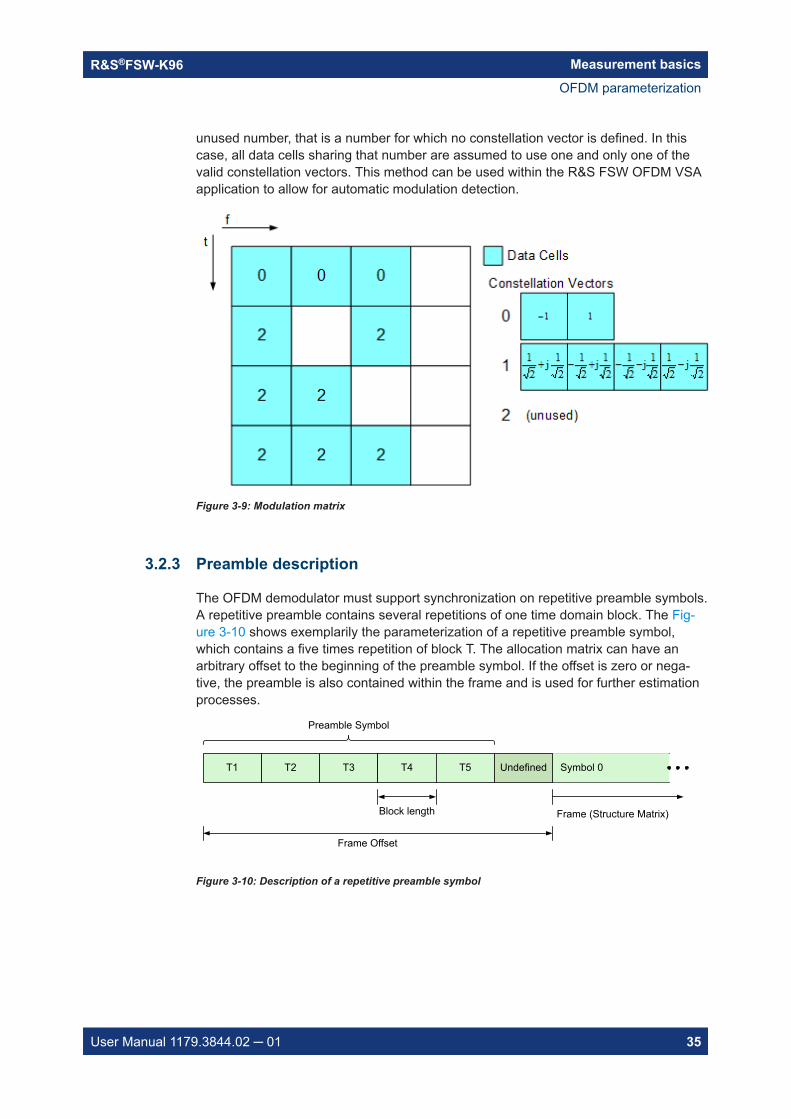
A modulation matrix contains numbers to the underlying constellation vector for eachcell, which is defined as data cell in the allocation matrix. Clusters of data cells with thesame modulation therefore share the same number. A data cell can also contain an
OFDM parameterization
Measurement basicsR&S®FSW-K96
35User Manual 1179.3844.02 ─ 01
unused number, that is a number for which no constellation vector is defined. In thiscase, all data cells sharing that number are assumed to use one and only one of thevalid constellation vectors. This method can be used within the R&S FSW OFDM VSAapplication to allow for automatic modulation detection.
Figure 3-9: Modulation matrix
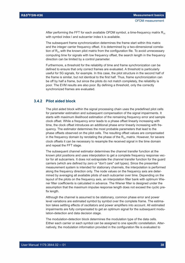
3.2.3 Preamble description
The OFDM demodulator must support synchronization on repetitive preamble symbols.A repetitive preamble contains several repetitions of one time domain block. The Fig-ure 3-10 shows exemplarily the parameterization of a repetitive preamble symbol,which contains a five times repetition of block T. The allocation matrix can have anarbitrary offset to the beginning of the preamble symbol. If the offset is zero or nega-tive, the preamble is also contained within the frame and is used for further estimationprocesses.
T2 T3 T4 T5
Block length Frame (Structure Matrix)
Undefined
Frame Offset
Symbol 0T1
Preamble Symbol
Figure 3-10: Description of a repetitive preamble symbol
OFDM parameterization

Measurement basicsR&S®FSW-K96
36User Manual 1179.3844.02 ─ 01
3.3 Channel filter
The R&S FSW OFDM VSA application can use the internal channel filter of the instru-ment or apply an adjustable channel filter. The filter bandwidth of the internal channelfilter is fully equalized within the digital hardware.
Alternatively to the internal filters, you can apply a channel filter with adjustable band-width and slope characteristics to the input signal. The R&S FSW OFDM VSA applica-tion then designs a window-based finite impulse response filter. The bandwidth isdefined as two times the 6-dB cutoff frequency. The 50-dB cutoff frequency determinesthe slope characteristics.
Choosing the correct filter settings is a trade-off between selectivity and filter impulseresponse length. A steep filter leads to superior selectivity between adjacent channels.On the other hand, such a filter has a long channel impulse response, which can pro-duce intersymbol interference if used in systems with small guard intervals. Flat filtersrequire a higher distance between channels and possibly attenuate the outer carriersof the signal. In contrast, the channel impulse response is short and suited for systemswith short guard intervals.
The adjustable channel filter performs a decimation at its output. Thus, the user-defina-ble maximum output sample rate is reduced compared to the internal filter setting.
0 0.05 0.1 0.15 0.2 0.25 0.3 0.35 0.4 0.45 0.5-100
-90
-80
-70
-60
-50
-40
-30
-20
-10
0
10
Normalized Frequency
Freq
uenc
y R
espo
nse
[dB
]
Adjustable Channel Filter
LowNormalHigh
Figure 3-11: Output decimation by an adjustable channel filter
Channel filter

Measurement basicsR&S®FSW-K96
37User Manual 1179.3844.02 ─ 01
3.4 OFDM measurement
BurstDetection
ON / OFF
TimeSync
RoughCompensate
Freq. Offset
FFT
FFT_SHIFT
FrameSync R_lk
MAX_BIN_OFFSET
Freq / ClockEstimation Compensate Channel
EstimationCPE / GainEstimation Compensate Modulation
DetectionData
Decision
Freq. / Clock Offset Channel CPE / Gain
A_lkR_lk
Freq / ClockEstimation Compensate Channel
EstimationCPE / GainEstimation
Freq. / Clock Offset Channel CPE / Gain
R_lk
A_lk A_lk
User Defined Compensation
EVM Measurement
R_lk w/o frame syncCapture
Buffer
R_lk
PHASE_TRACKINGTIMING_TRACKINGGAIN_TRACKINGCHANNEL_COMP
A_lk
Synchronization Block
Pilot Aided Block
Data Aided Block Measurement Block
PREAMBLE / CP
Figure 3-12: Block diagram of the R&S FSW OFDM VSA application
The block diagram in Figure 3-12 shows the R&S FSW OFDM VSA application proc-ess from the capture buffer containing the I/Q data to the actual analysis block. Thesignal processing chain can be divided in four major blocks:
● Synchronization block............................................................................................. 37● Pilot aided block......................................................................................................38● Data aided block..................................................................................................... 39● Measurement block.................................................................................................39
3.4.1 Synchronization block
The synchronization starts with a burst detection that extracts transmission areaswithin a burst signal by a power threshold. For seamless transmission, as is the case inmost broadcast systems, it is possible to bypass this block. The following time synchro-nization uses either the preamble or the cyclic prefix of each OFDM symbol to find theoptimum starting point for the FFT by a correlation metric. If preamble synchronizationis selected, the correlation is done between successive blocks of a repetitive preamblestructure. Alternatively, the cyclic prefix synchronization correlates the guard interval ofeach symbol with the end of the FFT part. In addition, both methods return an estima-tion of the fractional frequency offset by evaluating the phase of the correlation maxi-mum. This frequency offset has to be compensated before the FFT to avoid intercarrierinterference.
By default, the FFT starting point is put in the center of the guard interval assuming asymmetric impulse response, but it can optionally be shifted within the guard interval.
OFDM measurement
Measurement basicsR&S®FSW-K96
38User Manual 1179.3844.02 ─ 01
After performing the FFT for each available OFDM symbol, a time-frequency matrix Rl,k
with symbol index l and subcarrier index k is available.
The subsequent frame synchronization determines the frame start within this matrixand the integer carrier frequency offset. It is determined by a two-dimensional correla-tion of Rl,k with the known pilot matrix from the configuration file. To avoid unnecessarycomputing time for signals with low frequency offset, the search length in the frequencydirection can be limited by a control parameter.
Furthermore, a threshold for the reliability of time and frame synchronization can bedefined to ensure that only correct frames are evaluated. A threshold is particularlyuseful for 5G signals, for example. In this case, the pilot structure in the second half ofthe frame is similar, but not identical to the first half. Thus, frame synchronization canbe off by half a frame, but since the pilots do not match completely, the reliability ispoor. The EVM results are also poor. By defining a threshold, only the correctlysynchronized frames are evaluated.
3.4.2 Pilot aided block
The pilot aided block within the signal processing chain uses the predefined pilot cellsfor parameter estimation and subsequent compensation of the signal impairments. Itstarts with maximum likelihood estimation of the remaining frequency error and sampleclock offset. While a frequency error leads to a phase offset linearly increasing withtime, the clock offset introduces an additional phase error linearly increasing with fre-quency. The estimator determines the most probable parameters that lead to thephase offsets observed on the pilot cells. The resulting offset values are compensatedin the frequency domain by rerotating the phase of the Rl,k matrix. However, for severeclock offsets it can be necessary to resample the received signal in the time domainand repeat the FFT stage.
The subsequent channel estimator determines the channel transfer function at theknown pilot positions and uses interpolation to get a complete frequency response vec-tor for all subcarriers. It does not extrapolate the channel transfer function for the guardcarriers (which are defined by zero or "don't care" cell types). Since the presentedmeasurement system is intended for stationary channels, the interpolation is performedalong the frequency direction only. The node values on the frequency axis are deter-mined by averaging all available pilots of each subcarrier over time. Depending on thelayout of the pilots on the frequency axis, an interpolation filter bank with optimum Wie-ner filter coefficients is calculated in advance. The Wiener filter is designed under theassumption that the maximum impulse response length does not exceed the cyclic pre-fix length.
Although the channel is assumed to be stationary, common phase error and powerlevel variations are estimated symbol by symbol over the complete frame. The estima-tion takes settling effects of oscillators and power amplifiers into account. All estimatedimpairments are fully compensated to get an optimum signal for the subsequent modu-lation-detection and data decision stage.
The modulation-detection block determines the modulation type of the data cells.Either each carrier or each symbol can be assigned to one specific constellation. Alter-natively, the modulation information provided in the configuration file is evaluated to
OFDM measurement

Measurement basicsR&S®FSW-K96
39User Manual 1179.3844.02 ─ 01
extract clusters of data cells with consistent modulation. The estimator uses a maxi-mum likelihood approach. Each cluster of data cells is compared with all possible mod-ulation hypotheses and the most probable constellation for each cluster is used for thesubsequent data decision. The data decision block finally outputs a reference signalmatrix Al,k which is an optimum estimate of the actual transmitted OFDM frame.
3.4.3 Data aided block
The data aided block can be activated optionally to refine the parameter estimationswith the help of the reference signal. Whereas the previous stages could only includepilot cells for the estimation algorithms, the data aided part can treat data cells as addi-tional pilots. Thus, the accuracy of the estimates increases in good signal to noiseenvironments without data decision errors. However, if the reference signal matrix Al,k
contains falsely decided data cells, the data aided estimation part can corrupt theresults and should be omitted.
3.4.4 Measurement block
The last part of the signal processing chain comprises the user defined compensationand the measurement of modulation quality. The measurement block takes thereceived OFDM symbols Rl,k and the previously determined reference OFDM symbolsAl,k to calculate the error vector magnitude (EVM). The received OFDM symbols canoptionally be compensated using phase, timing and level deviations and the channeltransfer function.
3.5 Sample rate and maximum usable I/Q bandwidth forRF input
Definitions
● Input sample rate (ISR): the sample rate of the useful data provided by the deviceconnected to the input of the R&S FSW
● (User, Output) Sample rate (SR): the user-defined sample rate (e.g. in the "DataAcquisition" dialog box in the "I/Q Analyzer" application) which is used as the basisfor analysis or output
● Usable I/Q (analysis) bandwidth: the bandwidth range in which the signalremains undistorted in regard to amplitude characteristic and group delay; thisrange can be used for accurate analysis by the R&S FSW
● Record length: the number of I/Q samples to capture during the specified mea-surement time; calculated as the measurement time multiplied by the sample rate
For the I/Q data acquisition, digital decimation filters are used internally in theR&S FSW. The passband of these digital filters determines the maximum usable I/Qbandwidth. In consequence, signals within the usable I/Q bandwidth (passband)
Sample rate and maximum usable I/Q bandwidth for RF input

Measurement basicsR&S®FSW-K96
40User Manual 1179.3844.02 ─ 01
remain unchanged, while signals outside the usable I/Q bandwidth (passband) aresuppressed. Usually, the suppressed signals are noise, artifacts, and the second IFsideband. If frequencies of interest to you are also suppressed, try to increase the out-put sample rate, which increases the maximum usable I/Q bandwidth.
Bandwidth extension options
You can extend the maximum usable I/Q bandwidth provided by the R&S FSW in thebasic installation by adding options. These options can either be included in the initialinstallation (B-options) or updated later (U-options). The maximum bandwidth providedby the individual option is indicated by its number, for example, B40 extends the band-width to 40 MHz.
Note that the U-options as of U40 always require all lower-bandwidth options as a pre-requisite, while the B-options already include them.
As a rule, the usable I/Q bandwidth is proportional to the output sample rate. Yet, whenthe I/Q bandwidth reaches the bandwidth of the analog IF filter (at very high outputsample rates), the curve breaks.
● Available bandwidth extension options................................................................... 40● Relationship between sample rate, record length and usable I/Q bandwidth......... 41● R&S FSW without additional bandwidth extension options.................................... 43● R&S FSW with I/Q bandwidth extension option B40 or U40...................................43● R&S FSW with I/Q bandwidth extension option B80 or U80...................................44● R&S FSW with activated I/Q bandwidth extension option B160 or U160............... 44● R&S FSW with activated I/Q bandwidth extension option B320/U320................... 44● R&S FSW with activated I/Q bandwidth extension option B512............................. 45● R&S FSW with activated I/Q bandwidth extension option B1200........................... 47● R&S FSW with activated I/Q bandwidth extension option B2001........................... 49● R&S FSW with activated I/Q bandwidth extension option B2000........................... 51● R&S FSW with activated I/Q bandwidth extension option B5000........................... 52● R&S FSW with activated I/Q bandwidth extension option B4001/B6001/B8001.... 53
3.5.1 Available bandwidth extension options
Table 3-2: Available bandwidth extension options
Max. usableI/Q band-width
Required B-option Required U-options
28 MHz - -
40 MHz B40 U40
80 MHz B80 U40+U80 orB40+U80
160 MHz B160 U40+U80+U160 orB40+U80+U160 orB80+U160
Sample rate and maximum usable I/Q bandwidth for RF input

Measurement basicsR&S®FSW-K96
41User Manual 1179.3844.02 ─ 01
Max. usableI/Q band-width
Required B-option Required U-options
320 MHz B320 U40+U80+U160+U320 orB40+U80+U160+U320 orB80+U160+U320 orB160+U320
512 MHz B512 U40+U80+U512 orB40+U80+U512 orB80+U512 or
1200 MHz B1200 B40 + U80 + U1200 orB80 + U1200
2000 MHz B2000 U2000
2000 MHz B2001 U2001
4000 MHz B4001 U4001
5000 MHz B5000 U5000
6000 MHz B6001 U6001
8000 MHz B8001 U8001
3.5.2 Relationship between sample rate, record length and usable I/Qbandwidth
Up to the maximum bandwidth, the following rule applies:
Usable I/Q bandwidth = 0.8 * Output sample rate
Regarding the record length, the following rule applies:
Record length = Measurement time * sample rate
Maximum record length for RF input
The maximum record length, that is, the maximum number of samples that can be cap-tured, depends on the sample rate.
For activated option B1200, see Table 3-14.
For activated option B2001, see Chapter 3.5.10, "R&S FSW with activated I/Q band-width extension option B2001", on page 49.
For activated option B2000, see Chapter 3.5.11, "R&S FSW with activated I/Q band-width extension option B2000", on page 51.
For activated option B5000, see Chapter 3.5.12, "R&S FSW with activated I/Q band-width extension option B5000", on page 52.
For activated option B4001/B6001/B8001, see Chapter 3.5.13, "R&S FSW with activa-ted I/Q bandwidth extension option B4001/B6001/B8001", on page 53.
Sample rate and maximum usable I/Q bandwidth for RF input

Measurement basicsR&S®FSW-K96
42User Manual 1179.3844.02 ─ 01
Table 3-3: Maximum record length (without I/Q bandwidth extension options R&S FSW-B160/-B320/-B512/-B1200/-B2001/-B4001/-B6001/-B8001)
Sample rate Maximum record length
100 Hz to 200 MHz 440 Msamples
200 MHz to 20 GHz
(upsampling)
220 Msamples
The Figure 3-13 shows the maximum usable I/Q bandwidths depending on the outputsample rates.
Usable I/Q bandwidth[MHz]
20
Output sample rate fout [MHz]20 40
10
30
40
60 80 100 120 140 160 180 200
50
60
70
80
I/Q bandwidths for RF input
Option B40 / U40
Option B80 / U80or deactivated
option B160 / U160RF-Input:BW = 0.80
* fout
Without BW extension options
110
120
130
140
150
160
90
100
Wideband board:
BW = 0.80 * fout
Activated option B160 / U160
... 10000
28
Figure 3-13: Relationship between maximum usable I/Q bandwidth and output sample rate with andwithout bandwidth extensions
Restricting the maximum bandwidth manually
By default, all installed bandwidth extension options are activated, allowing for themaximum bandwidth for measurements on the R&S FSW. However, sometimes the
Sample rate and maximum usable I/Q bandwidth for RF input

Measurement basicsR&S®FSW-K96
43User Manual 1179.3844.02 ─ 01
maximum bandwidth is not necessary. For example, due to the correlation of bothparameters, high sample rates automatically lead to an extended analysis bandwidth.However, while a high sample rate can be necessary (for example due to postprocess-ing in an OFDM system), the wide bandwidth is not necessarily required.
On the other hand, low sample rates lead to small usable I/Q bandwidths. To ensurethe availability of the required bandwidth, the minimum required bandwidth for thespecified sample rate can be selected (via remote command only).
Thus, if one of the bandwidth extension options is installed, the maximum bandwidthcan be restricted manually to a value that can improve the measurement (see "Maxi-mum Bandwidth" on page 84). In this case, the hardware of the "regular" RF path isused, rather than the hardware required by the bandwidth extension options.
The following improvements can be achieved:● Longer measurement time for sample rates under 300 MHz● Data processing becomes up to 10 times faster● Digital baseband output becomes available (with bandwidth extension options that
do not support output)
General notes and restrictions● The memory extension option R&S FSW-B106 is only available together with the
R&S FSW-B160 or B320 bandwidth extension options.● The memory extension option R&S FSW-B108 is only available together with the
R&S FSW-B1200/-B2001/-B800R options.● The memory extension option R&S FSW-B124 is only available together with the
R&S FSW-B4001/B6001/B8001 options.
3.5.3 R&S FSW without additional bandwidth extension options
Sample rate: 100 Hz - 20 GHz
Maximum I/Q bandwidth: 28 MHz
Table 3-4: Maximum I/Q bandwidth
Sample rate Maximum I/Q bandwidth
100 Hz to 28 MHz Proportional up to maximum 28 MHz
28 MHz to 20 GHz 28 MHz
3.5.4 R&S FSW with I/Q bandwidth extension option B40 or U40
Sample rate: 100 Hz - 20 GHz
Maximum bandwidth: 40 MHz
Sample rate and maximum usable I/Q bandwidth for RF input

Measurement basicsR&S®FSW-K96
44User Manual 1179.3844.02 ─ 01
Table 3-5: Maximum I/Q bandwidth
Sample rate Maximum I/Q bandwidth
100 Hz to 50 MHz Proportional up to maximum 40 MHz
50 MHz to 20 GHz 40 MHz
3.5.5 R&S FSW with I/Q bandwidth extension option B80 or U80
Sample rate: 100 Hz - 20 GHz
Maximum bandwidth: 80 MHzTable 3-6: Maximum I/Q bandwidth
Sample rate Maximum I/Q bandwidth
100 Hz to 100 MHz Proportional up to maximum 80 MHz
100 MHz to 20 GHz 80 MHz
3.5.6 R&S FSW with activated I/Q bandwidth extension option B160 orU160
Sample rate: 100 Hz - 20 GHz
Maximum bandwidth: 160 MHzTable 3-7: Maximum I/Q bandwidth
Sample rate Maximum I/Q bandwidth
100 Hz to 200 MHz Proportional up to maximum 160 MHz
200 MHz to 20 GHz 160 MHz
Table 3-8: Maximum record length with activated I/Q bandwidth extension option B160 or U160
Sample rate Maximum record length
100 Hz to 200 MHz 440 Msamples
220 Msamples
3.5.7 R&S FSW with activated I/Q bandwidth extension option B320/U320
Table 3-9: Maximum I/Q bandwidth
Sample rate Maximum I/Q bandwidth
100 Hz to 400 MHz Proportional up to maximum 320 MHz
400 MHz to 20 GHz 320 MHz
Sample rate and maximum usable I/Q bandwidth for RF input

Measurement basicsR&S®FSW-K96
45User Manual 1179.3844.02 ─ 01
Figure 3-14: Relationship between maximum usable I/Q bandwidth and output sample rate for activeR&S FSW-B320
Table 3-10: Maximum record length with activated I/Q bandwidth extension option B320 or U320
Sample rate Maximum record length
100 Hz to 200 MHz*) 440 Msamples
With R&S FSW-B106 option: 1400 Msamples
200 MHz to 468 MHz 470 Msamples * sample rate / 1GHz
With R&S FSW-B106 option: 1400 Msamples * sample rate / 1GHz
468 MHz to 20 GHz 220 Msamples
With R&S FSW-B106 option: 700 Msamples
*) for sample rates up to 200 MHz the I/Q bandwidth extension B320 is not used
3.5.8 R&S FSW with activated I/Q bandwidth extension option B512
The bandwidth extension option R&S FSW-B512 provides measurement bandwidthsup to 512 MHz.
Sample rate and maximum usable I/Q bandwidth for RF input

Measurement basicsR&S®FSW-K96
46User Manual 1179.3844.02 ─ 01
Table 3-11: Maximum I/Q bandwidth
Sample rate Maximum I/Q bandwidth
100 Hz to 600 MHz 0.8 * sample rate (up to maximum 512 MHz)
600 MHz to 20 GHz 512 MHz
Figure 3-15: Relationship between maximum usable I/Q bandwidth and output sample rate for activeR&S FSW-B512
Table 3-12: Maximum record length with activated I/Q bandwidth extension option R&S FSW-B512
Sample rate Maximum record length
100 Hz to 20 GHz 440 Msamples
Notes and restrictions for R&S FSW-B512● The memory extension options R&S FSW-B106/-B108/-B124 are not available
together with the -B512 option.
Sample rate and maximum usable I/Q bandwidth for RF input

Measurement basicsR&S®FSW-K96
47User Manual 1179.3844.02 ─ 01
Bandwidths between 480 MHz and 512 MHz with R&S FSW-B512 optionNote the irregular behavior of the sample rate/usable I/Q bandwidth relationship forbandwidths between 480 MHz and 512 MHz with the -B512 options, depending onwhich setting you change.For compatibility reasons, the common relationship is maintained for bandwidths≤ 480 MHz:Usable I/Q bandwidth = 0.8 * output sample rateHowever, to make use of the maximum sample rate of 600 MHz at the maximum band-width of 512 MHz, there is an exception. If you change the bandwidth between480 MHz and 500 MHz, the sample rate is adapted according to the relationship:Output sample rate = usable I/Q bandwidth / (500/600)OrOutput sample rate = usable I/Q bandwidth / 0.8333When using option R&S FSW-B512R, if you change the bandwidth between500 MHz and 512 MHz, the sample rate is adapted according to the relationship:Output sample rate = usable I/Q bandwidth / (512/600)OrOutput sample rate = usable I/Q bandwidth / 0.8533On the other hand, if you decrease the sample rate under 600 MHz, the I/Q band-width is adapted according to the common relationship:Usable I/Q bandwidth = 0.8 * output sample rate.
3.5.9 R&S FSW with activated I/Q bandwidth extension option B1200
The bandwidth extension option R&S FSW-B1200 provides measurement bandwidthsup to 1200 MHz.
Table 3-13: Maximum I/Q bandwidth
Sample rate Maximum I/Q bandwidth
100 Hz to 600 MHz 0.8 * sample rate
600 MHz 0.8533 * sample rate (=512 MHz)
600 MHz to 1500 MHz 0.8 * sample rate *)
1500 MHz to 20 GHz 1200 MHz
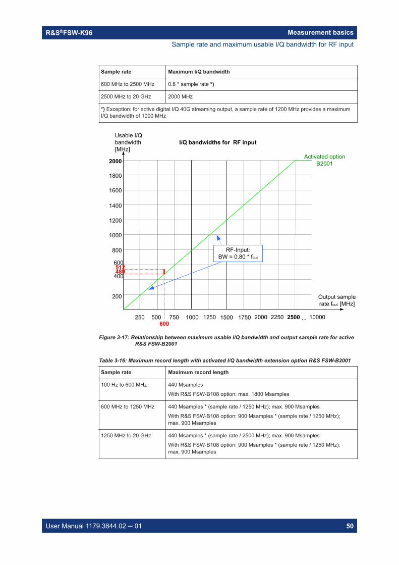
*) Exception: for active digital I/Q 40G streaming output, a sample rate of 1200 MHz provides a maximumI/Q bandwidth of 1000 MHz
Sample rate and maximum usable I/Q bandwidth for RF input

Measurement basicsR&S®FSW-K96
48User Manual 1179.3844.02 ─ 01
Figure 3-16: Relationship between maximum usable I/Q bandwidth and output sample rate for activeR&S FSW-B1200
Table 3-14: Maximum record length with activated I/Q bandwidth extension option R&S FSW-B1200
Sample rate Maximum record length
100 Hz to 600 MHz 440 Msamples
With R&S FSW-B108 option: max. 1800 Msamples
600 MHz to 1250 MHz 480 Msamples * (sample rate / 1250 MHz); max. 440 Msamples
With R&S FSW-B108 option: 990 Msamples * (sample rate / 1250 MHz);max. 900 Msamples
1250 MHz to 20 GHz max. 440 Msamples
With R&S FSW-B108 option: 900 Msamples * (sample rate / 1250 MHz);max. 900 Msamples
Notes and restrictions for R&S FSW-B1200● The memory extension option R&S FSW-B106 is not available together with the
B1200 option.● When the R&S FSW-B1200 option is active, only an external trigger (or no trigger)
is available.
Sample rate and maximum usable I/Q bandwidth for RF input

Measurement basicsR&S®FSW-K96
49User Manual 1179.3844.02 ─ 01
Irregular behavior in bandwidths between 480 MHz and R&S FSW512 MHz withR&S FSW-B1200 optionNote that the B1200 bandwidth extension option has the same irregular behavior of thesample rate/usable I/Q bandwidth relationship for bandwidths between 480 MHz and512 MHz as the B512 option. The R&S FSW uses the same hardware for both optionsup to 512 MHz.For compatibility reasons, the common relationship is maintained for bandwidths≤ 480 MHz:Output sample rate = usable I/Q bandwidth / 0.8However, to make use of the maximum sample rate of 600 MHz at the maximum band-width of 500 MHz, there is an exception. If you change the bandwidth between480 MHz and 500 MHz, the sample rate is adapted according to the relationship:Output sample rate = usable I/Q bandwidth / (500/600)OrOutput sample rate = usable I/Q bandwidth / 0.8333If you change the bandwidth between 500 MHz and 512 MHz, the sample rate isadapted according to the relationship:Output sample rate = usable I/Q bandwidth / (512/600)OrOutput sample rate = usable I/Q bandwidth / 0.8533If you increase the bandwidth above 512 MHz, the common relationship is maintainedagain:Output sample rate = usable I/Q bandwidth / 0.8On the other hand, if you set the sample rate to 600 MHz, the I/Q bandwidth is set to:Output sample rate * 0.8533 = 512 MHzHowever, if you decrease the sample rate under 600 MHz or increase the samplerate above 600 MHz, the I/Q bandwidth is adapted according to the common relation-ship:Usable I/Q bandwidth = 0.8 * output sample rate.
3.5.10 R&S FSW with activated I/Q bandwidth extension option B2001
The (internal) bandwidth extension option R&S FSW-B2001 provides measurementbandwidths up to 2 GHz, with no additional devices required.
Table 3-15: Maximum I/Q bandwidth
Sample rate Maximum I/Q bandwidth
100 Hz to 600 MHz 0.8 * sample rate
600 MHz 0.8533 * sample rate (=512 MHz)
*) Exception: for active digital I/Q 40G streaming output, a sample rate of 1200 MHz provides a maximumI/Q bandwidth of 1000 MHz
Sample rate and maximum usable I/Q bandwidth for RF input
Measurement basicsR&S®FSW-K96
50User Manual 1179.3844.02 ─ 01
Sample rate Maximum I/Q bandwidth
600 MHz to 2500 MHz 0.8 * sample rate *)
2500 MHz to 20 GHz 2000 MHz
*) Exception: for active digital I/Q 40G streaming output, a sample rate of 1200 MHz provides a maximumI/Q bandwidth of 1000 MHz
Usable I/Q bandwidth[MHz]
400
Output sample rate fout [MHz]
200
600
800
250 500 750 1000 1250 1500 1750 2500
I/Q bandwidths for RF input
Activated option B2001
... 10000
1200
1000
1400
1600
1800
2000
600
480512
2000
RF-Input:BW = 0.80 * fout
2250
Figure 3-17: Relationship between maximum usable I/Q bandwidth and output sample rate for activeR&S FSW-B2001
Table 3-16: Maximum record length with activated I/Q bandwidth extension option R&S FSW-B2001
Sample rate Maximum record length
100 Hz to 600 MHz 440 Msamples
With R&S FSW-B108 option: max. 1800 Msamples
600 MHz to 1250 MHz 440 Msamples * (sample rate / 1250 MHz); max. 900 Msamples
With R&S FSW-B108 option: 900 Msamples * (sample rate / 1250 MHz);max. 900 Msamples
1250 MHz to 20 GHz 440 Msamples * (sample rate / 2500 MHz); max. 900 Msamples
With R&S FSW-B108 option: 900 Msamples * (sample rate / 1250 MHz);max. 900 Msamples
Sample rate and maximum usable I/Q bandwidth for RF input

Measurement basicsR&S®FSW-K96
51User Manual 1179.3844.02 ─ 01
Notes and restrictions for R&S FSW-B2001● The memory extension option R&S FSW-B106 is not available together with the
B2001 option.● When the R&S FSW-B2001 option is active, only an external trigger (or no trigger)
is available.
Irregular behavior in bandwidths between 480 MHz and 512 MHz with R&S FSW-B2001 optionNote that the B2001 bandwidth extension option has the same irregular behavior of thesample rate/usable I/Q bandwidth relationship for bandwidths between 480 MHz and512 MHz as the -B512 options. The R&S FSW uses the same hardware for bothoptions up to 512 MHz.For compatibility reasons, the common relationship is maintained for bandwidths≤ 480 MHz:Output sample rate = usable I/Q bandwidth / 0.8However, to make use of the maximum sample rate of 600 MHz at the maximum band-width of 500 MHz, there is an exception. If you change the bandwidth between480 MHz and 500 MHz, the sample rate is adapted according to the relationship:Output sample rate = usable I/Q bandwidth / (500/600)OrOutput sample rate = usable I/Q bandwidth / 0.8333If you change the bandwidth between 500 MHz and 512 MHz, the sample rate isadapted according to the relationship:Output sample rate = usable I/Q bandwidth / (512/600)OrOutput sample rate = usable I/Q bandwidth / 0.8533If you increase the bandwidth above 512 MHz, the common relationship is maintainedagain:Output sample rate = usable I/Q bandwidth / 0.8On the other hand, if you set the sample rate to 600 MHz, the I/Q bandwidth is set to:Output sample rate * 0.8533 = 512 MHzHowever, if you decrease the sample rate under 600 MHz or increase the samplerate above 600 MHz, the I/Q bandwidth is adapted according to the common relation-ship:Usable I/Q bandwidth = 0.8 * output sample rate.
3.5.11 R&S FSW with activated I/Q bandwidth extension option B2000
The bandwidth extension option R&S FSW-B2000 provides measurement bandwidthsup to 2 GHz.
Sample rate and maximum usable I/Q bandwidth for RF input
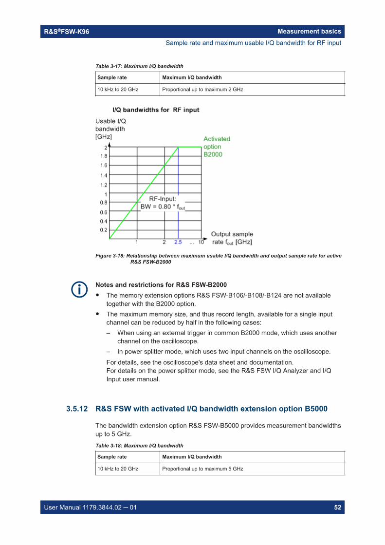
Measurement basicsR&S®FSW-K96
52User Manual 1179.3844.02 ─ 01
Table 3-17: Maximum I/Q bandwidth
Sample rate Maximum I/Q bandwidth
10 kHz to 20 GHz Proportional up to maximum 2 GHz
Figure 3-18: Relationship between maximum usable I/Q bandwidth and output sample rate for activeR&S FSW-B2000
Notes and restrictions for R&S FSW-B2000● The memory extension options R&S FSW-B106/-B108/-B124 are not available
together with the B2000 option.● The maximum memory size, and thus record length, available for a single input
channel can be reduced by half in the following cases:– When using an external trigger in common B2000 mode, which uses another
channel on the oscilloscope.– In power splitter mode, which uses two input channels on the oscilloscope.For details, see the oscilloscope's data sheet and documentation.For details on the power splitter mode, see the R&S FSW I/Q Analyzer and I/QInput user manual.
3.5.12 R&S FSW with activated I/Q bandwidth extension option B5000
The bandwidth extension option R&S FSW-B5000 provides measurement bandwidthsup to 5 GHz.
Table 3-18: Maximum I/Q bandwidth
Sample rate Maximum I/Q bandwidth
10 kHz to 20 GHz Proportional up to maximum 5 GHz
Sample rate and maximum usable I/Q bandwidth for RF input

Measurement basicsR&S®FSW-K96
53User Manual 1179.3844.02 ─ 01
Figure 3-19: Relationship between maximum usable I/Q bandwidth and output sample rate for activeR&S FSW-B5000
Notes and restrictions for R&S FSW-B5000● The memory extension options R&S FSW-B106/-B108/-B124 are not available
together with the B5000 option.● The maximum memory size, and thus record length, available for a single input
channel can be reduced by half in the following cases:– When using an external trigger in common B5000 mode, which uses another
channel on the oscilloscope.– In power splitter mode, which uses two input channels on the oscilloscope.For details, see the oscilloscope's data sheet and documentation.For details on the power splitter mode, see the R&S FSW I/Q Analyzer and I/QInput user manual.
3.5.13 R&S FSW with activated I/Q bandwidth extension option B4001/B6001/B8001
The (internal) bandwidth extension options R&S FSW-B4001/B6001/B8001 providemeasurement bandwidths up to 4 GHz, 6 GHz or 8 GHz, respectively, with no addi-tional devices required. The B4001 option is activated automatically for bandwidthslarger than 80 MHz, if installed. The B6001 and B8001 options are activated automati-cally for bandwidths larger than 80 MHz and center frequencies above 18 GHz, ifinstalled.
The memory extension options R&S FSW-B106/-B108 are not available together withthe B4001/B6001/B8001 options.
Sample rate and maximum usable I/Q bandwidth for RF input

Measurement basicsR&S®FSW-K96
54User Manual 1179.3844.02 ─ 01
Table 3-19: Maximum I/Q bandwidth
Option Sample rate Maximum I/Q bandwidth
B4001 100 Hz to 5500 MHz 0.8 * sample rate
5500 MHz to 20 GHz 4400 MHz
B6001 100 Hz to 8000 MHz 0.8 * sample rate
8000 MHz to 20 GHz 6400 MHz
B8001 100 Hz to 10390 MHz 0.8 * sample rate
10390 MHz to 20 GHz 8312 MHz
Usable I/Q bandwidth[MHz]
2000
Output sample rate fout [MHz]
1000
3000
4000
1000 2000 3000 4000 5000 6000 7000 10000
I/Q bandwidths for RF input
Activated option B8001
... max
6000
5000
7000
8000
8000
RF-Input:BW = 0.80 * fout
9000
Activated option B6001
Activated option B4001
4400
6400
8312
5500 10390
Figure 3-20: Relationship between maximum usable I/Q bandwidth and output sample rate for activeR&S FSW-B4001/B6001/B8001
Table 3-20: Maximum record length with activated I/Q bandwidth extension option R&S FSW-B4001/B6001/B8001
Sample rate Maximum record length
100 Hz to 100 MHz 440 Msamples
100 MHz to 20 GHz 1039 Msamples
100 MHz to 5.32 GHz 1039 Msamples
With R&S FSW-B124 option: max. 5600 Msamples
5.32 GHz to 10.64 GHz 1039 Msamples
With R&S FSW-B124 option: max. 6440 Msamples
10.64 GHz to 20 GHz 1039 Msamples
With R&S FSW-B124 option: max. 2800 Msamples
Sample rate and maximum usable I/Q bandwidth for RF input

Measurement basicsR&S®FSW-K96
55User Manual 1179.3844.02 ─ 01
Notes and restrictions for R&S FSW-B4001/B6001/B8001● If a R&S FSW-B4001/B6001/B8001 option is active, only an external trigger (or no
trigger) is available.
Sample rate and maximum usable I/Q bandwidth for RF input
Configuring OFDM VSA measurementsR&S®FSW-K96
56User Manual 1179.3844.02 ─ 01
4 Configuring OFDM VSA measurementsWhen you activate a measurement channel for the R&S FSW OFDM VSA application,a OFDM VSA measurement for the input signal is started automatically with the defaultconfiguration. The "OFDM VSA" menu is displayed and provides access to the mostimportant configuration functions.
General R&S FSW functionsThe application-independent functions for general tasks on the R&S FSW are alsoavailable for the R&S FSW OFDM VSA application and are described in the R&S FSWuser manual. In particular, the application supports the following functionality:● Data management● Test report functionality● General software preferences and information● Fast access panel
Importing and exporting I/Q dataThe I/Q data to be evaluated in the R&S FSW OFDM VSA application cannot only bemeasured by the R&S FSW OFDM VSA application itself, it can also be imported tothe application, provided it has the correct format. Furthermore, the evaluated I/Q datafrom the R&S FSW OFDM VSA application can be exported for further analysis inexternal applications.The import and export functions are available in the "Save/Recall" menu which is dis-played when you select the "Save" or "Open" icon in the toolbar.For details on importing and exporting I/Q data, see the R&S FSW base unit user man-ual.
● Configuration overview............................................................................................57● Signal description....................................................................................................58● Input, output and frontend settings..........................................................................62● Trigger settings....................................................................................................... 77● Data acquisition.......................................................................................................82● Sweep settings........................................................................................................86● Burst search............................................................................................................87● Result ranges..........................................................................................................88● Synchronization, demodulation and tracking.......................................................... 88● Adjusting settings automatically..............................................................................92

Configuring OFDM VSA measurementsR&S®FSW-K96
57User Manual 1179.3844.02 ─ 01
4.1 Configuration overview
Access: [Meas Config] > "Overview"
Throughout the measurement configuration, an overview of the most important cur-rently defined settings is provided in the "Overview".
Figure 4-1: Configuration "Overview" for the R&S FSW OFDM VSA application
In addition to the main measurement settings, the "Overview" provides quick access tothe main settings dialog boxes. Thus, you can easily configure an entire measurementchannel from input over processing to evaluation by stepping through the dialog boxesas indicated in the "Overview".
In particular, the "Overview" provides quick access to the following configuration dialogboxes (listed in the recommended order of processing):
1. Signal descriptionSee Chapter 4.2, "Signal description", on page 58
2. Input/FrontendSee Chapter 4.3, "Input, output and frontend settings", on page 62
3. TriggerSee Chapter 4.4, "Trigger settings", on page 77
4. Data acquisitionSee Chapter 4.5, "Data acquisition", on page 82
5. Burst searchSee Chapter 4.7, "Burst search", on page 87
6. Result range
Configuration overview
Configuring OFDM VSA measurementsR&S®FSW-K96
58User Manual 1179.3844.02 ─ 01
See Chapter 4.8, "Result ranges", on page 88
7. Synchronization and demodulation settingsSee Chapter 4.9, "Synchronization, demodulation and tracking", on page 88
8. TrackingSee Chapter 4.9, "Synchronization, demodulation and tracking", on page 88
9. Result configurationSee Chapter 6.1, "Result configuration", on page 118
To configure settings
► Select any button in the "Overview" to open the corresponding dialog box.Select a setting in the channel bar (at the top of the measurement channel tab) tochange a specific setting.
Preset Channel............................................................................................................. 58Specific Settings for...................................................................................................... 58
Preset ChannelSelect the "Preset Channel" button in the lower left-hand corner of the "Overview" torestore all measurement settings in the current channel to their default values.Note: Do not confuse the "Preset Channel" button with the [Preset] key, which restoresthe entire instrument to its default values and thus closes all channels on theR&S FSW (except for the default channel)!
Remote command: SYSTem:PRESet:CHANnel[:EXEC] on page 141
Specific Settings forThe channel can contain several windows for different results. Thus, the settings indi-cated in the "Overview" and configured in the dialog boxes vary depending on theselected window.Select an active window from the "Specific Settings for" selection list that is displayedin the "Overview" and in all window-specific configuration dialog boxes.The "Overview" and dialog boxes are updated to indicate the settings for the selectedwindow.
4.2 Signal description
Access: "Overview" > "Signal Description"
You must describe the expected input signal so that the R&S FSW OFDM VSA appli-cation can compare the measured signal to the expected reference signal. You canload an existing configuration file, or create one interactively using a wizard for the cur-rent input signal (see Chapter 5, "Creating a configuration file using the wizard",on page 94).
Signal description

Configuring OFDM VSA measurementsR&S®FSW-K96
59User Manual 1179.3844.02 ─ 01
The R&S FSW OFDM VSA application provides some sample files for I/Q input dataand configuration files in the C:\R_S\INSTR\USER\demo\OFDM-VSA directory.
Use Configuration File...................................................................................................59Load Configuration File................................................................................................. 59Create Configuration File.............................................................................................. 60Export Data (to Create Config File on Other PC)..........................................................60FFT Size........................................................................................................................60Cyclic Prefix Length...................................................................................................... 60Advanced Cyclic Prefix Configuration........................................................................... 60Different cyclic prefix lengths.........................................................................................60
└ Cyclic prefix definition per range (Symbols / Samples)...................................61Preamble Symbol Characteristics: Block Length.......................................................... 61Frame Start Offset.........................................................................................................61DFT-s-OFDM / SC-FDMA:Transform Precoding...........................................................61
Use Configuration FileDetermines whether the configuration from the currently loaded file is used for themeasurement. Alternatively, you can configure the OFDM signal manually.Remote command: CONFigure:SYSTem:CFILe on page 145
Load Configuration FileOpens a file selection dialog box to select the configuration (.XML) file for the mea-surement.Note: Configuration files with more than 100 different modulation types cannot be loa-ded.
Signal description

Configuring OFDM VSA measurementsR&S®FSW-K96
60User Manual 1179.3844.02 ─ 01
Remote command: MMEMory:LOAD:CFGFile on page 146
Create Configuration FileOpens a wizard that helps you create a new configuration file interactively. See Chap-ter 5, "Creating a configuration file using the wizard", on page 94.
Export Data (to Create Config File on Other PC)Exports the current settings to a .K96_wizv file. Use this input file to create a configu-ration file using the wizard on another PC.
FFT SizeDefines the length of an OFDM symbol in the time domain as the number of samples.This setting determines the number of samples used as input for each FFT calculation.This setting is not available if a configuration file is active (see "Use Configuration File"on page 59). In this case, the FFT length defined in the file is displayed for referenceonly.Remote command: CONFigure[:SYMBol]:NFFT on page 144
Cyclic Prefix LengthDefines the length of the cyclic prefix (CP) area between two OFDM symbols in sam-ples. The cyclic prefix area defines the guard interval and is expected to contain a copyof the samples at the end of the OFDM symbol.The cyclic prefix length must be smaller than or equal to the "FFT Size" on page 60.
Advanced Cyclic Prefix ConfigurationAdditional settings for non-conventional cyclic prefixes are displayed when you selectthe "Advanced" button, and hidden when you select "Basic".By default, "Conventional Mode" is assumed, that is: each OFDM symbol has thesame cyclic prefix length. Thus, only the basic cyclic prefix settings are shown.Remote command: CONFigure[:SYMBol]:GUARd:MODE on page 143
Different cyclic prefix lengthsSome OFDM signals change their cyclic prefix over time (e.g. 802.11ac). This settingdefines the behavior in such a case."Periodic" One "slot" that consists of the two defined ranges is repeated over
and over until the number of symbols specified by the result rangeparameter is reached. The ranges are repeated periodically, firstrange 1, then range 2, then range 1, etc.
Figure 4-2: Non-Conventional cyclic prefix case: Periodic mode
Signal description

Configuring OFDM VSA measurementsR&S®FSW-K96
61User Manual 1179.3844.02 ─ 01
"Non-Periodic" A fixed preamble has a different cyclic prefix length than the rest ofthe frame (e.g. WLAN 802.11ac signals). In this case, the length ofthe second range is extended until the end of the demodulated frame.Therefore, the length of the second range cannot be specified in thiscase.
Figure 4-3: Non-Conventional cyclic prefix case: Non-Periodic mode
Remote command: CONFigure[:SYMBol]:GUARd:PERiodic on page 144
Cyclic prefix definition per range (Symbols / Samples) ← Different cyclic prefixlengthsFor each range, configure the number of symbols the cyclic prefix length is applied to,and the length of the cyclic prefix as a number of samples.For non-periodic cyclic prefixes, the length of the second range cannot be specified. Itis extended to the end of the demodulated frame.Remote command: CONFigure[:SYMBol]:GUARd:NSYMbols<cp> on page 143CONFigure[:SYMBol]:NGUard<cp> on page 144
Preamble Symbol Characteristics: Block LengthInstead of using the cyclic prefix for the time synchronization, the R&S FSW OFDMVSA application can also use a preamble that contains repetitive blocks of samples (ifavailable in the signal). This setting specifies the length of one data block within therepetitive preamble as a number of samples.Remote command: CONFigure:PREamble:BLENgth on page 142
Frame Start OffsetSpecifies the time offset from the preamble start to the actual frame start as a numberof samples.Remote command: CONFigure:PREamble:FOFFset on page 142
DFT-s-OFDM / SC-FDMA:Transform PrecodingDFT-s-OFDM and SC-FDMA are different names for a method that can be applied tolower the crest factor of the RF signal.
Signal description

Configuring OFDM VSA measurementsR&S®FSW-K96
62User Manual 1179.3844.02 ─ 01
For DFT-s-OFDM, an additional digital Fourier transformation (DFT) is included in thetransmitter's signal processing stage, referred to as transform precoding. If this methodis used by the input signal, enable the "Transform Precoding" option. In this case, thereceiver (R&S FSW OFDM VSA application) decodes this precoding using an inverseDFT (iDFT). The iDFT is performed per OFDM symbol, using all data cells contained init.However, OFDM symbols that contain a pilot or a "Don't Care" cell are skipped. Zerocells do not cause the complete OFDM symbol to be skipped, only the zero cells areignored in the inverse DFT process.Therefore, it is important that all data cells are allocated correctly, that is:● No cell is falsely allocated as a data cell.● All data cells are allocated as data cells.Otherwise, the iDFT parameters (length, start, stop) are not correct and all data cells inthat OFDM symbol are demodulated inaccurately.If DFT-s-OFDM is enabled, take special care when editing the configuration file. Makesure that all cells are allocated correctly.Remote command: CONFigure:TPRecoding on page 145
4.3 Input, output and frontend settings
Access: "Overview" > "Input/Frontend"
Or: [INPUT/OUTPUT]
The R&S FSW can evaluate signals from different input sources.
The frequency and amplitude settings represent the frontend of the measurementsetup.
● Input settings...........................................................................................................62● Output settings........................................................................................................68● Frequency settings..................................................................................................71● Amplitude settings...................................................................................................73
4.3.1 Input settings
Access: "Overview" > "Input/Frontend" > "Input"
Or: [INPUT/OUTPUT]
Some settings are also available in the "Amplitude" tab of the "Amplitude" dialog box,see "Input Settings" on page 74.
Input, output and frontend settings

Configuring OFDM VSA measurementsR&S®FSW-K96
63User Manual 1179.3844.02 ─ 01
Input from other sourcesThe R&S FSW OFDM VSA application can also process input from the followingoptional sources:● I/Q input files● External mixer● Digital Baseband (I/Q) Interface (R&S FSW-B17)● Analog Baseband Interface (R&S FSW-B71)● Baseband oscilloscope input (R&S FSW-B2071)● 2 GHz / 5 GHz bandwidth extension (R&S FSW-B2000/B5000)● Probes
For details, see the R&S FSW I/Q Analyzer and I/Q Input user manual.
● Radio frequency input............................................................................................. 63● Settings for input from I/Q data files........................................................................66
4.3.1.1 Radio frequency input
Access: "Overview" > "Input/Frontend" > "Input" > "Radio Frequency"
Or: [INPUT/OUTPUT] > "Input Source Config" > "Input" > "Radio Frequency"
The default input source for the R&S FSW is the radio frequency.
Input, output and frontend settings

Configuring OFDM VSA measurementsR&S®FSW-K96
64User Manual 1179.3844.02 ─ 01
RF input protectionThe RF input connector of the R&S FSW must be protected against signal levels thatexceed the ranges specified in the data sheet. Therefore, the R&S FSW is equippedwith an overload protection mechanism for DC and signal frequencies up to 30 MHz.This mechanism becomes active as soon as the power at the input mixer exceeds thespecified limit. It ensures that the connection between RF input and input mixer is cutoff.When the overload protection is activated, an error message is displayed in the statusbar ("INPUT OVLD"), and a message box informs you that the RF input was discon-nected. Furthermore, a status bit (bit 3) in the STAT:QUES:POW status register is set.In this case, you must decrease the level at the RF input connector and then close themessage box. Then measurement is possible again. Reactivating the RF input is alsopossible via the remote command INPut<ip>:ATTenuation:PROTection:RESet.
Radio Frequency State................................................................................................. 64Input Coupling............................................................................................................... 64Impedance.................................................................................................................... 65Direct Path.................................................................................................................... 65High Pass Filter 1 to 3 GHz...........................................................................................65YIG-Preselector.............................................................................................................66Input Connector.............................................................................................................66
Radio Frequency StateActivates input from the "RF Input" connector.For R&S FSW85 models with two input connectors, you must define which inputsource is used for each measurement channel.
"Input 1" 1.00 mm RF input connector for frequencies up to 85 GHz (90 GHzwith option R&S FSW-B90G)
"Input2" 1.85 mm RF input connector for frequencies up to 67 GHzRemote command: INPut<ip>:SELect on page 149INPut<ip>:TYPE on page 150
Input CouplingThe RF input of the R&S FSW can be coupled by alternating current (AC) or direct cur-rent (DC).AC coupling blocks any DC voltage from the input signal. This is the default setting toprevent damage to the instrument. Very low frequencies in the input signal may be dis-torted.However, some specifications require DC coupling. In this case, you must protect theinstrument from damaging DC input voltages manually. For details, refer to the datasheet.
Input, output and frontend settings

Configuring OFDM VSA measurementsR&S®FSW-K96
65User Manual 1179.3844.02 ─ 01
Remote command: INPut<ip>:COUPling on page 147
ImpedanceThe R&S FSW has an internal impedance of 50 Ω. However, some applications useother impedance values. In order to match the impedance of an external application tothe impedance of the R&S FSW, an impedance matching pad can be inserted at theinput. If the type and impedance value of the used matching pad is known to theR&S FSW, it can convert the measured units accordingly so that the results are calcu-lated correctly.This function is not available for input from the optional Digital Baseband Interface. Notall settings are supported by all R&S FSW applications.The impedance conversion does not affect the level of the output signals (such as IF,video, demod, digital I/Q output)."50Ω" (Default:) no conversion takes place
"75Ω" The 50 Ω input impedance is transformed to a higher impedanceusing a 75 Ω adapter of the selected "Pad Type": "Series-R" (default)or "MLP" (Minimum Loss Pad)
"User" The 50 Ω input impedance is transformed to a user-defined impe-dance value according to the selected "Pad Type": "Series-R"(default) or "MLP" (Minimum Loss Pad)
Remote command: INPut<ip>:IMPedance on page 149INPut<ip>:IMPedance:PTYPe on page 149
Direct PathEnables or disables the use of the direct path for small frequencies.In spectrum analyzers, passive analog mixers are used for the first conversion of theinput signal. In such mixers, the LO signal is coupled into the IF path due to its limitedisolation. The coupled LO signal becomes visible at the RF frequency 0 Hz. This effectis referred to as LO feedthrough.To avoid the LO feedthrough the spectrum analyzer provides an alternative signal pathto the A/D converter, referred to as the direct path. By default, the direct path isselected automatically for RF frequencies close to zero. However, this behavior can bedisabled. If "Direct Path" is set to "Off", the spectrum analyzer always uses the analogmixer path."Auto" (Default) The direct path is used automatically for frequencies close
to zero."Off" The analog mixer path is always used.Remote command: INPut<ip>:DPATh on page 147
High Pass Filter 1 to 3 GHzActivates an additional internal highpass filter for RF input signals from 1 GHz to3 GHz. This filter is used to remove the harmonics of the analyzer to measure the har-monics for a DUT, for example.
Input, output and frontend settings
Configuring OFDM VSA measurementsR&S®FSW-K96
66User Manual 1179.3844.02 ─ 01
This function requires an additional hardware option.Note: For RF input signals outside the specified range, the high-pass filter has noeffect. For signals with a frequency of approximately 4 GHz upwards, the harmonicsare suppressed sufficiently by the YIG-preselector, if available.)Remote command: INPut<ip>:FILTer:HPASs[:STATe] on page 148
YIG-PreselectorEnables or disables the YIG-preselector, if available on the R&S FSW.
Note: Note that the YIG-preselector is active only on frequencies greater than 8 GHz.Therefore, switching the YIG-preselector on or off has no effect if the frequency isbelow that value.To make use of the optional 90 GHz frequency extension (R&S FSW-B90G), the YIG-preselector must be disabled.Remote command: INPut<ip>:FILTer:YIG[:STATe] on page 148
Input ConnectorDetermines which connector the input data for the measurement is taken from."RF" (Default:) The "RF Input" connector"RF Probe" The "RF Input" connector with an adapter for a modular probe
This setting is only available if a probe is connected to the "RF Input"connector.
"BasebandInput I"
The optional "Baseband Input I" connectorThis setting is only available if the optional "Analog Baseband Inter-face" is installed and active for input. It is not available for theR&S FSW67.For R&S FSW85 models with two input connectors, this setting isonly available for "Input 1".
Remote command: INPut<ip>:CONNector on page 146
4.3.1.2 Settings for input from I/Q data files
Access: "Overview" > "Input/Frontend" > "Input Source" > "I/Q File"
Or: [INPUT/OUTPUT] > "Input Source Config" > "Input Source" > "I/Q File"
Input, output and frontend settings

Configuring OFDM VSA measurementsR&S®FSW-K96
67User Manual 1179.3844.02 ─ 01
I/Q Input File State........................................................................................................ 67Select I/Q data file.........................................................................................................67File Repetitions............................................................................................................. 68
I/Q Input File StateEnables input from the selected I/Q input file.If enabled, the application performs measurements on the data from this file. Thus,most measurement settings related to data acquisition (attenuation, center frequency,measurement bandwidth, sample rate) cannot be changed. The measurement timecan only be decreased to perform measurements on an extract of the available dataonly.Note: Even when the file input is disabled, the input file remains selected and can beenabled again quickly by changing the state.Remote command: INPut<ip>:SELect on page 149
Select I/Q data fileOpens a file selection dialog box to select an input file that contains I/Q data.The I/Q data file must be in one of the following supported formats:● .iq.tar● .iqw● .csv● .mat● .wv● .aidFor details on formats, see the R&S FSW I/Q Analyzer and I/Q Input user manual.
Note: Only a single data stream or channel can be used as input, even if multiplestreams or channels are stored in the file.Note: For some file formats that do not provide the sample rate and measurement timeor record length, you must define these parameters manually. Otherwise the traces arenot visible in the result displays.The default storage location for I/Q data files is C:\R_S\INSTR\USER.
Input, output and frontend settings

Configuring OFDM VSA measurementsR&S®FSW-K96
68User Manual 1179.3844.02 ─ 01
Remote command: INPut<ip>:FILE:PATH on page 151
File RepetitionsDetermines how often the data stream is repeatedly copied in the I/Q data memory tocreate a longer record. If the available memory is not sufficient for the specified num-ber of repetitions, the largest possible number of complete data streams is used.Remote command: TRACe:IQ:FILE:REPetition:COUNt on page 153
4.3.2 Output settings
Access: [INPUT/OUTPUT] > "OUTPUT Config"
The R&S FSW OFDM VSA application can provide output to special connectors forother devices.
For details on connectors, refer to the R&S FSW Getting Started manual, "Front / RearPanel View" chapters.
Output settings can be configured via the [Input/Output] key or in the "Output" dialogbox.
Data Output...................................................................................................................69Noise Source Control.................................................................................................... 69Trigger 2/3.....................................................................................................................70
└ Output Type.................................................................................................... 70
Input, output and frontend settings

Configuring OFDM VSA measurementsR&S®FSW-K96
69User Manual 1179.3844.02 ─ 01
└ Level..................................................................................................... 71└ Pulse Length.........................................................................................71└ Send Trigger......................................................................................... 71
Data OutputDefines the type of signal available at one of the output connectors of the R&S FSW.
"IF" The measured IF value is provided at the IF/VIDEO/DEMOD outputconnector.For bandwidths up to 80 MHZ, the IF output is provided at the speci-fied "IF Out Frequency".If an optional bandwidth extension R&S FSW-B160/-B320/-B512 isused, the measured IF value is available at the "IF WIDE OUTPUT"connector. The frequency at which this value is output is determinedautomatically. It is displayed as the "IF Wide Out Frequency". Fordetails on the used frequencies, see the data sheet.This setting is not available for bandwidths larger than 512 MHz.
"2ND IF" The measured IF value is provided at the "IF OUT 2 GHz/ IF OUT5 GHz " output connector, if available, at a frequency of 2 GHz andwith a bandwidth of 2 GHz. The availability of this connector dependson the instrument model.This setting is not available if the optional 2 GHz / 5 GHz bandwidthextension (R&S FSW-B2000/B5000) is active.
Remote command: OUTPut<up>:IF[:SOURce] on page 176
Noise Source ControlThe R&S FSW provides a connector ("NOISE SOURCE CONTROL") with a 28 V volt-age supply for an external noise source. By switching the supply voltage for an exter-nal noise source on or off in the firmware, you can enable or disable the device asrequired.External noise sources are useful when you are measuring power levels that fall belowthe noise floor of the R&S FSW itself, for example when measuring the noise level ofan amplifier.In this case, you can first connect an external noise source (whose noise power level isknown in advance) to the R&S FSW and measure the total noise power. From thisvalue you can determine the noise power of the R&S FSW. Then when you measurethe power level of the actual DUT, you can deduct the known noise level from the totalpower to obtain the power level of the DUT.Remote command: DIAGnostic:SERVice:NSOurce on page 176
Input, output and frontend settings

Configuring OFDM VSA measurementsR&S®FSW-K96
70User Manual 1179.3844.02 ─ 01
Trigger 2/3
The trigger input and output functionality depends on how the variable "Trigger Input/Output" connectors are used."Trigger 1" "Trigger 1" is input only."Trigger 2" Defines the usage of the variable "Trigger Input/Output" connector on
the front panel(not available for R&S FSW85 models with 2 RF input connectors)
"Trigger 3" Defines the usage of the variable "Trigger 3 Input/Output" connectoron the rear panel
"Input" The signal at the connector is used as an external trigger source bythe R&S FSW. Trigger input parameters are available in the "Trigger"dialog box.
"Output" The R&S FSW sends a trigger signal to the output connector to beused by connected devices.Further trigger parameters are available for the connector.
Remote command: OUTPut<up>:TRIGger<tp>:DIRection on page 177
Output Type ← Trigger 2/3Type of signal to be sent to the output"Device Trig-gered"
(Default) Sends a trigger when the R&S FSW triggers.
"TriggerArmed"
Sends a (high level) trigger when the R&S FSW is in "Ready for trig-ger" state.This state is indicated by a status bit in the STATus:OPERation reg-ister (bit 5), as well as by a low-level signal at the "AUX" port (pin 9).
"User Defined" Sends a trigger when you select the "Send Trigger" button.In this case, further parameters are available for the output signal.
Remote command: OUTPut<up>:TRIGger<tp>:OTYPe on page 178
Input, output and frontend settings

Configuring OFDM VSA measurementsR&S®FSW-K96
71User Manual 1179.3844.02 ─ 01
Level ← Output Type ← Trigger 2/3Defines whether a high (1) or low (0) constant signal is sent to the trigger output con-nector.The trigger pulse level is always opposite to the constant signal level defined here. Forexample, for "Level" = "High", a constant high signal is output to the connector until youselect the Send Trigger function. Then, a low pulse is provided.
Remote command: OUTPut<up>:TRIGger<tp>:LEVel on page 177
Pulse Length ← Output Type ← Trigger 2/3Defines the duration of the pulse (pulse width) sent as a trigger to the output connector.Remote command: OUTPut<up>:TRIGger<tp>:PULSe:LENGth on page 179
Send Trigger ← Output Type ← Trigger 2/3Sends a user-defined trigger to the output connector immediately.Note that the trigger pulse level is always opposite to the constant signal level definedby the output Level setting. For example, for "Level" = "High", a constant high signal isoutput to the connector until you select the "Send Trigger" function. Then, a low pulseis sent.Which pulse level will be sent is indicated by a graphic on the button.Remote command: OUTPut<up>:TRIGger<tp>:PULSe:IMMediate on page 179
4.3.3 Frequency settings
Access: [FREQ] > "Frequency Config"
Input, output and frontend settings

Configuring OFDM VSA measurementsR&S®FSW-K96
72User Manual 1179.3844.02 ─ 01
Center Frequency......................................................................................................... 72Center Frequency Stepsize...........................................................................................72Frequency Offset...........................................................................................................72
Center FrequencyDefines the center frequency of the signal in Hertz.fmax and spanmin depend on the instrument and are specified in the data sheet.
Remote command: [SENSe:]FREQuency:CENTer on page 153
Center Frequency StepsizeDefines the step size when scrolling through center frequency values. The step sizecan be set to a predefined value, or it can be manually set to a user-defined value."Auto" The step size is set to the default value:
● using the rotary knob: 100 kHz● using the arrow keys: 1 MHz
"Manual" Defines a user-defined step size for the center frequency. Enter thestep size in the "Value" field.
Remote command: [SENSe:]FREQuency:CENTer:STEP:AUTO on page 154[SENSe:]FREQuency:CENTer:STEP on page 153
Frequency OffsetShifts the displayed frequency range along the x-axis by the defined offset.This parameter has no effect on the instrument's hardware, on the captured data, or ondata processing. It is simply a manipulation of the final results in which absolute fre-quency values are displayed. Thus, the x-axis of a spectrum display is shifted by aconstant offset if it shows absolute frequencies. However, if it shows frequencies rela-tive to the signal's center frequency, it is not shifted.A frequency offset can be used to correct the display of a signal that is slightly distortedby the measurement setup, for example.The allowed values range from -1 THz to 1 THz. The default setting is 0 Hz.
Input, output and frontend settings
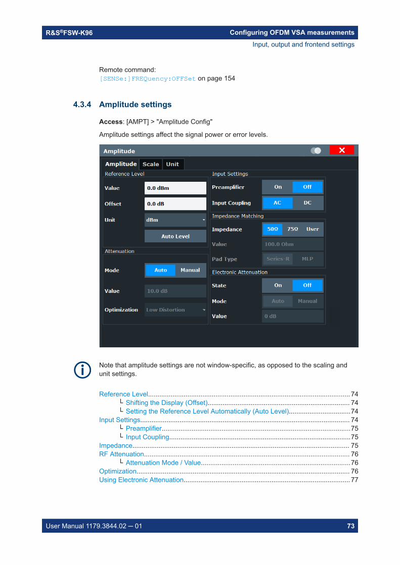
Configuring OFDM VSA measurementsR&S®FSW-K96
73User Manual 1179.3844.02 ─ 01
Remote command: [SENSe:]FREQuency:OFFSet on page 154
4.3.4 Amplitude settings
Access: [AMPT] > "Amplitude Config"
Amplitude settings affect the signal power or error levels.
Note that amplitude settings are not window-specific, as opposed to the scaling andunit settings.
Reference Level............................................................................................................ 74└ Shifting the Display (Offset)............................................................................ 74└ Setting the Reference Level Automatically (Auto Level).................................74
Input Settings................................................................................................................ 74└ Preamplifier.....................................................................................................75└ Input Coupling.................................................................................................75
Impedance.................................................................................................................... 75RF Attenuation.............................................................................................................. 76
└ Attenuation Mode / Value................................................................................76Optimization.................................................................................................................. 76Using Electronic Attenuation......................................................................................... 77
Input, output and frontend settings

Configuring OFDM VSA measurementsR&S®FSW-K96
74User Manual 1179.3844.02 ─ 01
Reference LevelThe reference level can also be used to scale power diagrams; the reference level isthen used for the calculation of the maximum on the y-axis.Since the hardware of the R&S FSW is adapted according to this value, it is recom-mended that you set the reference level close above the expected maximum signallevel. Thus you ensure an optimum measurement (no compression, good signal-to-noise ratio).Note: Note that for input from the External Mixer (R&S FSW-B21) the maximum refer-ence level also depends on the conversion loss; see the R&S FSW base unit usermanual for details.Remote command: DISPlay[:WINDow<n>]:TRACe<t>:Y[:SCALe]:RLEVel on page 155
Shifting the Display (Offset) ← Reference LevelDefines an arithmetic level offset. This offset is added to the measured level. In someresult displays, the scaling of the y-axis is changed accordingly.Define an offset if the signal is attenuated or amplified before it is fed into theR&S FSW so the application shows correct power results. All displayed power levelresults are shifted by this value.The setting range is ±200 dB in 0.01 dB steps.Note, however, that the internal reference level (used to adjust the hardware settings tothe expected signal) ignores any "Reference Level Offset". Thus, it is important to keepin mind the actual power level the R&S FSW must handle. Do not rely on the displayedreference level (internal reference level = displayed reference level - offset).Remote command: DISPlay[:WINDow<n>]:TRACe<t>:Y[:SCALe]:RLEVel:OFFSet on page 155
Setting the Reference Level Automatically (Auto Level) ← Reference LevelAutomatically determines a reference level which ensures that no overload occurs atthe R&S FSW for the current input data. At the same time, the internal attenuators andthe preamplifier (for analog baseband input: the full scale level) are adjusted. As aresult, the signal-to-noise ratio is optimized, while signal compression and clipping areminimized.To determine the required reference level, a level measurement is performed on theR&S FSW.If necessary, you can optimize the reference level further. Decrease the attenuationlevel manually to the lowest possible value before an overload occurs, then decreasethe reference level in the same way.Remote command: [SENSe:]ADJust:LEVel on page 155
Input SettingsSome input settings affect the measured amplitude of the signal, as well.For information on other input settings, see Chapter 4.3.1, "Input settings", on page 62.
Input, output and frontend settings

Configuring OFDM VSA measurementsR&S®FSW-K96
75User Manual 1179.3844.02 ─ 01
Preamplifier ← Input SettingsIf the (optional) internal preamplifier hardware is installed, a preamplifier can be activa-ted for the RF input signal.You can use a preamplifier to analyze signals from DUTs with low output power.Note: If an optional external preamplifier is activated, the internal preamplifier is auto-matically disabled, and vice versa.For all R&S FSW models except for R&S FSW85, the following settings are available:
"Off" Deactivates the preamplifier."15 dB" The RF input signal is amplified by about 15 dB."30 dB" The RF input signal is amplified by about 30 dB.For R&S FSW85 models, the input signal is amplified by 30 dB if the preamplifier isactivated.Remote command: INPut<ip>:GAIN:STATe on page 158INPut<ip>:GAIN[:VALue] on page 159
Input Coupling ← Input SettingsThe RF input of the R&S FSW can be coupled by alternating current (AC) or direct cur-rent (DC).AC coupling blocks any DC voltage from the input signal. This is the default setting toprevent damage to the instrument. Very low frequencies in the input signal may be dis-torted.However, some specifications require DC coupling. In this case, you must protect theinstrument from damaging DC input voltages manually. For details, refer to the datasheet.Remote command: INPut<ip>:COUPling on page 147
ImpedanceThe R&S FSW has an internal impedance of 50 Ω. However, some applications useother impedance values. In order to match the impedance of an external application tothe impedance of the R&S FSW, an impedance matching pad can be inserted at theinput. If the type and impedance value of the used matching pad is known to theR&S FSW, it can convert the measured units accordingly so that the results are calcu-lated correctly.This function is not available for input from the optional Digital Baseband Interface. Notall settings are supported by all R&S FSW applications.The impedance conversion does not affect the level of the output signals (such as IF,video, demod, digital I/Q output)."50Ω" (Default:) no conversion takes place
"75Ω" The 50 Ω input impedance is transformed to a higher impedanceusing a 75 Ω adapter of the selected "Pad Type": "Series-R" (default)or "MLP" (Minimum Loss Pad)
Input, output and frontend settings
Configuring OFDM VSA measurementsR&S®FSW-K96
76User Manual 1179.3844.02 ─ 01
"User" The 50 Ω input impedance is transformed to a user-defined impe-dance value according to the selected "Pad Type": "Series-R"(default) or "MLP" (Minimum Loss Pad)
Remote command: INPut<ip>:IMPedance on page 149INPut<ip>:IMPedance:PTYPe on page 149
RF AttenuationDefines the mechanical attenuation for RF input.This function is not available for input from the optional R&S Digital Baseband Inter-face.
Attenuation Mode / Value ← RF AttenuationThe RF attenuation can be set automatically as a function of the selected referencelevel (Auto mode). Automatic attenuation ensures that no overload occurs at the RFInput connector for the current reference level. It is the default setting.By default and when no (optional) electronic attenuation is available, mechanicalattenuation is applied.In "Manual" mode, you can set the RF attenuation in 1 dB steps (down to 0 dB). Otherentries are rounded to the next integer value. The range is specified in the data sheet.If the defined reference level cannot be set for the defined RF attenuation, the refer-ence level is adjusted accordingly and the warning "limit reached" is displayed.NOTICE! Risk of hardware damage due to high power levels. When decreasing theattenuation manually, ensure that the power level does not exceed the maximum levelallowed at the RF input, as an overload can lead to hardware damage.Remote command: INPut<ip>:ATTenuation on page 156INPut<ip>:ATTenuation:AUTO on page 156
OptimizationSelects the priority for signal processing after the RF attenuation has been applied.This function is only available under the following conditions:● One of the following options that provide a separate wideband processing path in
the R&S FSW is installed:– Bandwidth extension R&S FSW-B160/-B320 Extension Board 1, Revision 2 or
higher– Bandwidth extension R&S FSW-B512, B1200, B2001, B4001, B6001, or B8001– Real-time option R&S FSW-B160R
(Currently not supported for K161R, B512R and B800R/K800RE)● An I/Q bandwidth higher than 80 MHz is used. (Only in this case the wideband path
is used.)● The optional Digital Baseband Interface is not active."Low distortion"
(Default:) Optimized for low distortion by avoiding intermodulation"Low noise" Optimized for high sensitivity and low noise levels
If this setting is selected, "Low noise" is indicated in the channel infor-mation bar.
Input, output and frontend settings

Configuring OFDM VSA measurementsR&S®FSW-K96
77User Manual 1179.3844.02 ─ 01
Remote command: INPut<ip>:ATTenuation:AUTO:MODE on page 156
Using Electronic AttenuationIf the (optional) Electronic Attenuation hardware is installed on the R&S FSW, you canalso activate an electronic attenuator.In "Auto" mode, the settings are defined automatically; in "Manual" mode, you candefine the mechanical and electronic attenuation separately.Note: Electronic attenuation is not available for stop frequencies (or center frequenciesin zero span) above 15 GHz.In "Auto" mode, RF attenuation is provided by the electronic attenuator as much aspossible to reduce the amount of mechanical switching required. Mechanical attenua-tion can provide a better signal-to-noise ratio, however.When you switch off electronic attenuation, the RF attenuation is automatically set tothe same mode (auto/manual) as the electronic attenuation was set to. Thus, the RFattenuation can be set to automatic mode, and the full attenuation is provided by themechanical attenuator, if possible.The electronic attenuation can be varied in 1 dB steps. If the electronic attenuation ison, the mechanical attenuation can be varied in 5 dB steps. Other entries are roundedto the next lower integer value.For the R&S FSW85, the mechanical attenuation can be varied only in 10 dB steps.If the defined reference level cannot be set for the given attenuation, the referencelevel is adjusted accordingly and the warning "limit reached" is displayed in the statusbar.Remote command: INPut<ip>:EATT:STATe on page 158INPut<ip>:EATT:AUTO on page 157INPut<ip>:EATT on page 157
4.4 Trigger settings
Access: "Overview" > "Signal Capture" > "Trigger"
Or: [TRIG] > "Trigger Config"
The trigger settings define the beginning of a measurement.
Trigger settings

Configuring OFDM VSA measurementsR&S®FSW-K96
78User Manual 1179.3844.02 ─ 01
For step-by-step instructions on configuring triggered measurements, see theR&S FSW user manual.
Trigger Source...............................................................................................................78└ Free Run.........................................................................................................78└ External Trigger 1/2/3..................................................................................... 78└ External Channel 3......................................................................................... 79└ IF Power..........................................................................................................79└ Baseband Power.............................................................................................80└ I/Q Power........................................................................................................80└ RF Power........................................................................................................80└ Digital I/Q........................................................................................................ 80
Trigger Level................................................................................................................. 81Trigger Offset................................................................................................................ 81Hysteresis..................................................................................................................... 81Drop-Out Time...............................................................................................................81Coupling........................................................................................................................ 82Slope............................................................................................................................. 82Trigger Holdoff...............................................................................................................82
Trigger SourceDefines the trigger source. If a trigger source other than "Free Run" is set, "TRG" isdisplayed in the channel bar and the trigger source is indicated.Remote command: TRIGger[:SEQuence]:SOURce on page 162
Free Run ← Trigger SourceNo trigger source is considered. Data acquisition is started manually or automaticallyand continues until stopped explicitly.Remote command: TRIG:SOUR IMM, see TRIGger[:SEQuence]:SOURce on page 162
External Trigger 1/2/3 ← Trigger SourceData acquisition starts when the TTL signal fed into the specified input connectormeets or exceeds the specified trigger level.
Trigger settings

Configuring OFDM VSA measurementsR&S®FSW-K96
79User Manual 1179.3844.02 ─ 01
(See "Trigger Level" on page 81).Note: The "External Trigger 1" softkey automatically selects the trigger signal from the"TRIGGER 1 INPUT" connector on the front panel.For details, see the "Instrument Tour" chapter in the R&S FSW Getting Started manual.
"External Trigger 1"Trigger signal from the "TRIGGER 1 INPUT" connector.
"External Trigger 2"Trigger signal from the "TRIGGER 2 INPUT / OUTPUT" connector.For R&S FSW85 models, "Trigger 2" is not available due to the sec-ond RF input connector on the front panel.
"External Trigger 3"Trigger signal from the "TRIGGER 3 INPUT / OUTPUT" connector onthe rear panel.
Remote command: TRIG:SOUR EXT, TRIG:SOUR EXT2TRIG:SOUR EXT3See TRIGger[:SEQuence]:SOURce on page 162
External Channel 3 ← Trigger SourceData acquisition starts when the signal fed into the "Ch3" input connector on the oscil-loscope meets or exceeds the specified trigger level.Note: In previous firmware versions, the external trigger was connected to the "Ch2"input on the oscilloscope. As of firmware version R&S FSW 2.30, the "Ch3" input onthe oscilloscope must be used!This trigger source is only available if the optional 2 GHz / 5 GHz bandwidth extension(R&S FSW-B2000/B5000) is active (see R&S FSW I/Q Analyzer and I/Q Input UserManual).Note: Since the external trigger uses a second channel on the oscilloscope, the maxi-mum memory size, and thus record length, available for the input channel 1 may bereduced by half. For details, see the oscilloscope's data sheet and documentation.Remote command: TRIG:SOUR EXT, see TRIGger[:SEQuence]:SOURce on page 162
IF Power ← Trigger SourceThe R&S FSW starts capturing data as soon as the trigger level is exceeded aroundthe third intermediate frequency.For frequency sweeps, the third IF represents the start frequency. The trigger thresholddepends on the defined trigger level, as well as on the RF attenuation and preamplifi-cation. A reference level offset, if defined, is also considered. The trigger bandwidth atthe intermediate frequency depends on the RBW and sweep type. For details on avail-able trigger levels and trigger bandwidths see the instrument data sheet.For measurements on a fixed frequency (e.g. zero span or I/Q measurements), thethird IF represents the center frequency.This trigger source is only available for RF input.
Trigger settings

Configuring OFDM VSA measurementsR&S®FSW-K96
80User Manual 1179.3844.02 ─ 01
The available trigger levels depend on the RF attenuation and preamplification. A refer-ence level offset, if defined, is also considered.For details on available trigger levels and trigger bandwidths, see the data sheet.Remote command: TRIG:SOUR IFP, see TRIGger[:SEQuence]:SOURce on page 162
Baseband Power ← Trigger SourceDefines triggering on the baseband power (for baseband input via the optional DigitalBaseband Interface or the optional Analog Baseband Interface).Remote command: TRIG:SOUR BBP, see TRIGger[:SEQuence]:SOURce on page 162
I/Q Power ← Trigger SourceThis trigger source is not available if the optional Digital Baseband Interface or optionalAnalog Baseband Interface is used for input.Triggers the measurement when the magnitude of the sampled I/Q data exceeds thetrigger threshold.Remote command: TRIG:SOUR IQP, see TRIGger[:SEQuence]:SOURce on page 162
RF Power ← Trigger SourceDefines triggering of the measurement via signals which are outside the displayedmeasurement range.For this purpose, the instrument uses a level detector at the first intermediate fre-quency.The resulting trigger level at the RF input depends on the RF attenuation and preampli-fication. For details on available trigger levels, see the instrument's data sheet.Note: If the input signal contains frequencies outside of this range (e.g. for fullspanmeasurements), the measurement may be aborted. A message indicating the allowedinput frequencies is displayed in the status bar.A "Trigger Offset", "Trigger Polarity" and "Trigger Holdoff" (to improve the trigger stabil-ity) can be defined for the RF trigger, but no "Hysteresis".Remote command: TRIG:SOUR RFP, see TRIGger[:SEQuence]:SOURce on page 162
Digital I/Q ← Trigger SourceFor applications that process I/Q data, such as the I/Q Analyzer or optional applica-tions, and only if the optional Digital Baseband Interface is available:Defines triggering of the measurement directly via the "LVDS" connector. In the selec-tion list, specify which general purpose bit ("GP0" to "GP5") provides the trigger data.Note: If the Digital I/Q enhanced mode is used, i.e. the connected device supportstransfer rates up to 200 Msps, only the general purpose bits "GP0" and "GP1" areavailable as a Digital I/Q trigger source.The following table describes the assignment of the general purpose bits to the LVDSconnector pins.
Trigger settings

Configuring OFDM VSA measurementsR&S®FSW-K96
81User Manual 1179.3844.02 ─ 01
Table 4-1: Assignment of general purpose bits to LVDS connector pins
Bit LVDS pin
GP0 SDATA4_P - Trigger1
GP1 SDATA4_P - Trigger2
GP2 *) SDATA0_P - Reserve1
GP3 *) SDATA4_P - Reserve2
GP4 *) SDATA0_P - Marker1
GP5 *) SDATA4_P - Marker2
*): not available for Digital I/Q enhanced mode
Remote command: TRIG:SOUR GP0, see TRIGger[:SEQuence]:SOURce on page 162
Trigger LevelDefines the trigger level for the specified trigger source.For details on supported trigger levels, see the instrument data sheet.Remote command: TRIGger[:SEQuence]:LEVel[:EXTernal<port>] on page 161
Trigger OffsetDefines the time offset between the trigger event and the start of the measurement.
Offset > 0: Start of the measurement is delayed
Offset < 0: Measurement starts earlier (pretrigger)
Remote command: TRIGger[:SEQuence]:HOLDoff[:TIME] on page 160
HysteresisDefines the distance in dB to the trigger level that the trigger source must exceedbefore a trigger event occurs. Setting a hysteresis avoids unwanted trigger eventscaused by noise oscillation around the trigger level.This setting is only available for "IF Power" trigger sources. The range of the value isbetween 3 dB and 50 dB with a step width of 1 dB.Remote command: TRIGger[:SEQuence]:IFPower:HYSTeresis on page 160
Drop-Out TimeDefines the time that the input signal must stay below the trigger level before triggeringagain.Remote command: TRIGger[:SEQuence]:DTIMe on page 159
Trigger settings
Configuring OFDM VSA measurementsR&S®FSW-K96
82User Manual 1179.3844.02 ─ 01
CouplingIf the selected trigger source is "IF Power" or "External Channel 3", you can configurethe coupling of the external trigger to the oscilloscope.This setting is only available if the optional 2 GHz bandwidth extension is active.
"DC 50 Ω" Direct connection with 50 Ω termination, passes both DC and ACcomponents of the trigger signal.
"DC 1 MΩ" Direct connection with 1 MΩ termination, passes both DC and ACcomponents of the trigger signal.
"AC" Connection through capacitor, removes unwanted DC and very low-frequency components.
Remote command: TRIGger[:SEQuence]:OSCilloscope:COUPling on page 162
SlopeFor all trigger sources except time, you can define whether triggering occurs when thesignal rises to the trigger level or falls down to it.When using the optional 2 GHz / 5 GHz bandwidth extension (R&S FSW-B2000/B5000) with an IF power trigger, only rising slopes can be detected.Remote command: TRIGger[:SEQuence]:SLOPe on page 162
Trigger HoldoffDefines the minimum time (in seconds) that must pass between two trigger events.Trigger events that occur during the holdoff time are ignored.Remote command: TRIGger[:SEQuence]:IFPower:HOLDoff on page 160
4.5 Data acquisition
Configure how data is to be acquired in the "Data Acquisition" dialog box.
Data acquisition

Configuring OFDM VSA measurementsR&S®FSW-K96
83User Manual 1179.3844.02 ─ 01
Capture Time.................................................................................................................83Capture Length............................................................................................................. 83Sample Rate................................................................................................................. 83Maximum Bandwidth.....................................................................................................84Swap I/Q....................................................................................................................... 84Filter State.....................................................................................................................846-dB Bandwidth.............................................................................................................8550-dB Bandwidth...........................................................................................................85Highpass Filter State.....................................................................................................856-dB Bandwidth.............................................................................................................8550-dB Bandwidth...........................................................................................................86
Capture TimeSpecifies the duration (and therefore the amount of data) to be captured in the capturebuffer. If the capture time is too short, demodulation will fail. In particular, if the resultlength does not fit in the capture buffer, demodulation will fail.Remote command: [SENSe:]SWEep:TIME on page 167
Capture LengthDefines the number of samples to be captured during each measurement. Therequired Capture Time is adapted accordingly.A maximum of 8 000 000 samples can be captured.Remote command: [SENSe:]SWEep:LENGth on page 166
Sample RateDefines the I/Q data sample rate of the R&S FSW.
Data acquisition

Configuring OFDM VSA measurementsR&S®FSW-K96
84User Manual 1179.3844.02 ─ 01
Note that the sample rate in the R&S FSW software must correspond to the OFDMsystem sample rate, otherwise demodulation may fail.Remote command: TRACe:IQ:SRATe on page 167
Maximum BandwidthDefines the maximum bandwidth to be used by the R&S FSW for I/Q data acquisition.Which options are available depends on which bandwidth extension options are instal-led.This setting is only available if a bandwidth extension option greater than 160 MHz isinstalled on the R&S FSW. Otherwise the maximum bandwidth is determined automati-cally."Auto" (Default:) All installed bandwidth extension options are enabled. The
currently available maximum bandwidth is allowed.Note that using bandwidth extension options greater than 160 MHzmay cause more spurious effects.
"80 MHz" Restricts the analysis bandwidth to a maximum of 80 MHz.The bandwidth extension options greater than 160 MHz are disabled.
"160 MHz" Restricts the analysis bandwidth to a maximum of 160 MHz. Thebandwidth extension option for 320 MHz is disabled.(Not available or required if other bandwidth extension options largerthan 320 MHz are installed.)
"512 MHz" Restricts the analysis bandwidth to a maximum of 512 MHz. Largerbandwidth extension options are disabled.
"1200 MHz" Restricts the analysis bandwidth to a maximum of 1200 MHz. Largerbandwidth extension options are disabled.
Remote command: TRACe:IQ:WBANd[:STATe] on page 167TRACe:IQ:WBANd:MBWidth on page 168
Swap I/QActivates or deactivates the inverted I/Q modulation. If the I and Q parts of the signalfrom the DUT are interchanged, the R&S FSW can do the same to compensate for it.
On I and Q signals are interchanged
Inverted sideband, Q+j*I
Off I and Q signals are not interchanged
Normal sideband, I+j*Q
Remote command: [SENSe:]SWAPiq on page 166
Filter StateDefines whether a channel filter - and a highpass filter, if active - is applied to the I/Qdata before OFDM demodulation.
Data acquisition

Configuring OFDM VSA measurementsR&S®FSW-K96
85User Manual 1179.3844.02 ─ 01
Remote command: INPut<ip>:FILTer:CHANnel[:LPASs][:STATe] on page 165
6-dB BandwidthConfigures the bandwidth of the channel filter at which an attenuation of 6 dB isreached (see Figure 4-4). The filter bandwidth cannot be higher than the current Sam-ple Rate. If necessary, the filter bandwidth is adapted to the current sample rate.
Figure 4-4: Definition of filter bandwidths
Remote command: INPut<ip>:FILTer:CHANnel[:LPASs]:SDBBw on page 165
50-dB BandwidthConfigures the 50-dB bandwidth of the channel filter. The 50-dB bandwidth is the band-width at which the filter reaches an attenuation of 50 dB (see Figure 4-4). This band-width must always be larger than the "6-dB Bandwidth" on page 85. If necessary, the50-dB bandwidth is adapted to the current 6-dB bandwidth.Remote command: INPut<ip>:FILTer:CHANnel[:LPASs]:FDBBw on page 165
Highpass Filter StateActivates or deactivates an additional internal highpass filter.Remote command: INPut<ip>:FILTer:CHANnel:HPASs[:STATe] on page 164
6-dB BandwidthConfigures the bandwidth of the high pass filter at which an attenuation of 6 dB isreached (see Figure 4-4). The filter bandwidth cannot be higher than the current 6-dBBandwidth of the channel filter. If necessary, the filter bandwidth is adapted to thesame value.Remote command: INPut<ip>:FILTer:CHANnel:HPASs:SDBBw on page 164
Data acquisition
Configuring OFDM VSA measurementsR&S®FSW-K96
86User Manual 1179.3844.02 ─ 01
50-dB BandwidthIndicates the 50-dB bandwidth of the high pass filter. The 50-dB bandwidth is the band-width at which the filter reaches an attenuation of 50 dB (see Figure 4-4). This band-width must always be smaller than the 6-dB Bandwidth of the high pass filter.The 50-dB bandwidth cannot be defined manually. It is automatically determinedaccording to the relation between the 6-dB bandwidth and the 50-dB bandwidth of thechannel filter (see 6-dB Bandwidth and 50-dB Bandwidth).Remote command: INPut<ip>:FILTer:CHANnel:HPASs:FDBBw? on page 164
4.6 Sweep settings
Access: [Sweep]
The sweep settings define how often data from the input signal is acquired and thenevaluated.
Continuous Sweep / Run Cont......................................................................................86Single Sweep / Run Single............................................................................................86Refresh..........................................................................................................................87Statistic Config / Max No of Frames to Analyze............................................................87
Continuous Sweep / Run ContAfter triggering, starts the measurement and repeats it continuously until stopped. Thisis the default setting.While the measurement is running, the "Continuous Sweep" softkey and the [RUNCONT] key are highlighted. The running measurement can be aborted by selecting thehighlighted softkey or key again. The results are not deleted until a new measurementis started.Note: Sequencer. If the Sequencer is active, the "Continuous Sweep" softkey only con-trols the sweep mode for the currently selected channel. However, the sweep modeonly takes effect the next time the Sequencer activates that channel, and only for achannel-defined sequence. In this case, a channel in continuous sweep mode is sweptrepeatedly.Furthermore, the [RUN CONT] key controls the Sequencer, not individual sweeps.[RUN CONT] starts the Sequencer in continuous mode.For details on the Sequencer, see the R&S FSW User Manual.
Remote command: INITiate<n>:CONTinuous on page 181
Single Sweep / Run SingleWhile the measurement is running, the "Single Sweep" softkey and the [RUN SINGLE]key are highlighted. The running measurement can be aborted by selecting the high-lighted softkey or key again.Note: Sequencer. If the Sequencer is active, the "Single Sweep" softkey only controlsthe sweep mode for the currently selected channel. However, the sweep mode onlytakes effect the next time the Sequencer activates that channel, and only for a chan-
Sweep settings

Configuring OFDM VSA measurementsR&S®FSW-K96
87User Manual 1179.3844.02 ─ 01
nel-defined sequence. In this case, the Sequencer sweeps a channel in single sweepmode only once.Furthermore, the [RUN SINGLE] key controls the Sequencer, not individual sweeps.[RUN SINGLE] starts the Sequencer in single mode.If the Sequencer is off, only the evaluation for the currently displayed channel is upda-ted.For details on the Sequencer, see the R&S FSW User Manual.
Remote command: INITiate<n>[:IMMediate] on page 181
RefreshRepeats the evaluation of the data currently in the capture buffer without capturing newdata.Remote command: INITiate:REFResh on page 181
Statistic Config / Max No of Frames to AnalyzeDefines the maximum number of OFDM frames from the current capture buffer to beincluded in analysis.If a configuration file is available, the contents of the file determine the frame. If no fileis available, a single result range is considered a frame.Remote command: [SENSe:]DEMod:FORMat:MAXFrames on page 169
4.7 Burst search
Access: "Overview" > "Burst Search"
Or: "Meas Setup" > "Burst Search"
During a burst search, the capture buffer is searched for bursts that comply with thesignal description. If no bursts are detected, the entire capture buffer is considered tobe a single burst. A list of the detected bursts is passed on to the next processingstage.
See also Chapter 3.4, "OFDM measurement", on page 37.
Burst Search StateActivates or deactivates a burst search.Remote command: [SENSe:]DEMod:FORMat:BURSt on page 168
Burst search
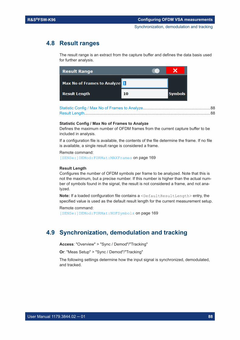
Configuring OFDM VSA measurementsR&S®FSW-K96
88User Manual 1179.3844.02 ─ 01
4.8 Result ranges
The result range is an extract from the capture buffer and defines the data basis usedfor further analysis.
Statistic Config / Max No of Frames to Analyze............................................................88Result Length................................................................................................................ 88
Statistic Config / Max No of Frames to AnalyzeDefines the maximum number of OFDM frames from the current capture buffer to beincluded in analysis.If a configuration file is available, the contents of the file determine the frame. If no fileis available, a single result range is considered a frame.Remote command: [SENSe:]DEMod:FORMat:MAXFrames on page 169
Result LengthConfigures the number of OFDM symbols per frame to be analyzed. Note that this isnot the maximum, but a precise number. If this number is higher than the actual num-ber of symbols found in the signal, the result is not considered a frame, and not ana-lyzed.Note: If a loaded configuration file contains a <DefaultResultLength> entry, thespecified value is used as the default result length for the current measurement setup.Remote command: [SENSe:]DEMod:FORMat:NOFSymbols on page 169
4.9 Synchronization, demodulation and tracking
Access: "Overview" > "Sync / Demod"/"Tracking"
Or: "Meas Setup" > "Sync / Demod"/"Tracking"
The following settings determine how the input signal is synchronized, demodulated,and tracked.
Synchronization, demodulation and tracking

Configuring OFDM VSA measurementsR&S®FSW-K96
89User Manual 1179.3844.02 ─ 01
Time Synchronization....................................................................................................89Parameter Estimation....................................................................................................89Modulation Detection.................................................................................................... 90Synchronization Thresholds..........................................................................................90
└ Minimum Time Sync Metric.............................................................................90└ Minimum Frame Sync Metric.......................................................................... 91
Phase Tracking............................................................................................................. 91Timing Tracking.............................................................................................................91Level Tracking...............................................................................................................91Channel Compensation.................................................................................................91FFT Shift relative to Cyclic Prefix Length...................................................................... 92Maximum Carrier Offset................................................................................................ 92Cyclic Delay.................................................................................................................. 92
Time SynchronizationSpecifies the synchronization method in the time domain."Cyclic Prefix" The cyclic prefix method performs a correlation of the cyclic prefix
with the end of the FFT interval."Preamble" The preamble method searches for the repetitive preamble blocks.Remote command: [SENSe:]DEMod:TSYNc on page 172
Parameter EstimationDefines which parts of the OFDM signal are used for the parameter estimation.This setting is only available if a configuration file is loaded and active (see "Use Con-figuration File" on page 59). In manual configuration mode without a configuration file,no parameter estimation is performed."Pilot-Aided" Uses only the predefined pilot cells for parameter estimation."Pilot And Data-Aided"
Uses both pilots and detected data cells for an additional synchroni-zation step.
Synchronization, demodulation and tracking

Configuring OFDM VSA measurementsR&S®FSW-K96
90User Manual 1179.3844.02 ─ 01
Remote command: [SENSe:]DEMod:FSYNc on page 171
Modulation DetectionSpecifies how the modulation of the data cells is detected.The R&S FSW OFDM VSA application can use the modulation configured in the con-figuration file for each cell.Alternatively, the R&S FSW OFDM VSA application tries to detect the used modulationautomatically based on the available modulation types (which are also defined in theconfiguration file). For automatic detection, the R&S FSW OFDM VSA application ana-lyzes the modulation type per carrier or per symbol.This setting is only available if a configuration file is loaded and active (see "Use Con-figuration File" on page 59)."ConfigurationFile"
The modulation format configured for the cell is used.Note that if the actual modulation of a constellation point differs fromthe configured modulation for the cell, the EVM is increased.
"Symbolwise" A common modulation format for all data cells within one OFDM sym-bol is determined.
"Carrierwise" A common modulation format for all data cells within one OFDM car-rier is determined.
Remote command: [SENSe:]DEMod:MDETect on page 171
Synchronization ThresholdsIf you require particular reliability in synchronization results, define thresholds for thesuccess of synchronization required to calculate results. The current reliability is indica-ted in the Signal Flow.High thresholds are useful if several similar, but not identical frames, must be distin-guished. In this case, it is important that the application synchronizes only to the cor-rect frame to obtain correct results.On the other hand, if the signal quality is poor, only a low level of reliability in synchro-nization can be achieved. In this case, high thresholds can prevent the application fromevaluating any frames at all.For details, see Chapter 3.4.1, "Synchronization block", on page 37.
Minimum Time Sync Metric ← Synchronization ThresholdsDefines the minimum reliability required for time synchronization.Values between 0 and 1 are allowed, where:● 0: low threshold, very poor reliability is sufficient to synchronize successfully
(always fulfilled)● 1: high threshold, time synchronization must be absolutely reliable to be successful
(only possible for ideal signal).The default value is 0.5, that means: for reliability of 50 %, time synchronization is suc-cessful.Remote command: [SENSe:]DEMod:THReshold:TIME on page 171
Synchronization, demodulation and tracking

Configuring OFDM VSA measurementsR&S®FSW-K96
91User Manual 1179.3844.02 ─ 01
Minimum Frame Sync Metric ← Synchronization ThresholdsDefines the minimum correlation rate of the CP or preamble for frame synchronizationto be successful.Values between 0 and 1 are allowed, where:● 0: low threshold, a very poor correlation is sufficient to synchronize successfully
(always fulfilled)● 1: high threshold, correlation must be very precise for frame synchronization to be
successful (only possible for ideal signal).The default value is 0.5, that means: for a correlation of 50 %, frame synchronization issuccessful.Remote command: [SENSe:]DEMod:THReshold:FRAMe on page 172
Phase TrackingDefines whether phase tracking is used to improve the signal quality. The compensa-tion is done on a per-symbol basis.This setting is only available if a configuration file is loaded and active (see "Use Con-figuration File" on page 59).Remote command: SENSe:TRACking:PHASe on page 173
Timing TrackingDefines whether timing tracking is used to improve the signal quality (for sample clockdeviations). The compensation is done on a per-symbol basis.This setting is only available if a configuration file is loaded and active (see "Use Con-figuration File" on page 59).Remote command: SENSe:TRACking:TIME on page 173
Level TrackingDefines whether level tracking is used to improve the signal quality (for power leveldeviations). The compensation is done on a per-symbol basis.This setting is only available if a configuration file is loaded and active (see "Use Con-figuration File" on page 59).Remote command: SENSe:TRACking:LEVel on page 173
Channel CompensationDefines whether channel tracking is used to improve the signal quality (for the channeltransfer function). The compensation is done on a per-carrier basis.This setting is only available if a configuration file is loaded and active (see "Use Con-figuration File" on page 59).Remote command: [SENSe:]COMPensate:CHANnel on page 170
Synchronization, demodulation and tracking

Configuring OFDM VSA measurementsR&S®FSW-K96
92User Manual 1179.3844.02 ─ 01
FFT Shift relative to Cyclic Prefix LengthDefines the starting point of the FFT relative to the cyclic prefix length. Thus, you canshift the FFT start sample within the guard interval. Shifting is useful if relevant parts ofthe channel impulse response fall outside the cyclic prefix interval.A value of 0 is the first sample; a value of 1.0 is the last sample of the cyclic prefix.
Remote command: [SENSe:]DEMod:FFTShift on page 170
Maximum Carrier OffsetThe R&S FSW OFDM VSA application can compensate for possible carrier offsets.However, searching for offsets slows down the measurement. This setting defines therange of carriers in which the R&S FSW OFDM VSA application searches for an offset.To eliminate the search for carrier offset altogether, set the number of carriers to 0. Inthis case, the center frequency offset must be less than half the carrier distance toobtain useful results.This setting is only available if a configuration file is loaded and active (see "Use Con-figuration File" on page 59).Remote command: [SENSe:]DEMod:COFFset on page 170
Cyclic DelayDefines a cyclic shift of the FFT values for each OFDM symbol on the transmitter endbefore adding the cyclic prefix. This known shift should be compensated in the receiverto get a correct channel phase response.Remote command: [SENSe:]DEMod:CDD on page 170
4.10 Adjusting settings automatically
Access: "Auto Set"
Depending on the R&S FSW, some settings can be adjusted by the instrument auto-matically according to the current measurement settings. To do so, a measurement isperformed.
To activate the automatic adjustment of a setting from the R&S FSW, select the corre-sponding function in the "Auto Set" menu or in the configuration dialog box for the set-ting, where available.
Adjusting settings automatically

Configuring OFDM VSA measurementsR&S®FSW-K96
93User Manual 1179.3844.02 ─ 01
Adjusting settings automatically during triggered measurementsWhen you select an auto adjust function, a measurement is performed to determinethe optimal settings. If you select an auto adjust function for a triggered measurement,you are asked how the R&S FSW should behave:● (Default:) The measurement for adjustment waits for the next trigger● The measurement for adjustment is performed without waiting for a trigger.
The trigger source is temporarily set to "Free Run". After the measurement is com-pleted, the original trigger source is restored. The trigger level is adjusted as fol-lows for "IF Power" and "RF Power" triggers:Trigger level = Reference level - 15 dB
Remote command:[SENSe:]ADJust:CONFigure:TRIGger on page 175
Setting the Reference Level Automatically (Auto Level)Automatically determines a reference level which ensures that no overload occurs atthe R&S FSW for the current input data. At the same time, the internal attenuators andthe preamplifier (for analog baseband input: the full scale level) are adjusted. As aresult, the signal-to-noise ratio is optimized, while signal compression and clipping areminimized.To determine the required reference level, a level measurement is performed on theR&S FSW.If necessary, you can optimize the reference level further. Decrease the attenuationlevel manually to the lowest possible value before an overload occurs, then decreasethe reference level in the same way.Remote command: [SENSe:]ADJust:LEVel on page 155
Adjusting settings automatically
Creating a configuration file using the wizardR&S®FSW-K96
94User Manual 1179.3844.02 ─ 01
5 Creating a configuration file using the wiz-ardThe R&S FSW-K96 Configuration File Wizard (referred to as wizard here) is a tool thatsupports you in defining the configuration of your OFDM signal directly in the R&SFSW OFDM VSA application.
The R&S FSW OFDM VSA application has to know the configuration of the OFDM sys-tem to be able to demodulate an OFDM signal correctly. By configuration, we refer tothe complete description of the OFDM system:● The number of subcarriers (i.e. the FFT size)● The number of symbols● The number of samples in the cyclic prefix (also referred to as guard length)● The position (carrier number, symbol number) of the
– Pilot symbols– Data symbols– Zero symbols– "Do not care" symbols
● The modulation format of the data symbols (e.g. QPSK, 16QAM etc.)● The I/Q values of the pilot symbols● Optional: the definition of the preamble
This section describes how to generate the OFDM system configuration file in the R&SFSW OFDM VSA application for the current input signal.
The R&S FSW OFDM VSA application provides some sample files for I/Q input dataand configuration files in the C:\R_S\INSTR\USER\demo\OFDM-VSA directory.It is available from the Windows "Start" menu.
To start the R&S FSW-K96 Configuration File Wizard
1. Configure the required input signal in the R&S FSW OFDM VSA application, eitherfrom a connected instrument or from an input file.
2. Select "Overview" > "Signal Description" > "Create New Configuration File".
● Understanding the R&S FSW-K96 Configuration File Wizard display.................... 95● Configuration steps............................................................................................... 102● Reference of wizard menu functions.....................................................................107● Example: creating a configuration file from an input signal...................................110

Creating a configuration file using the wizardR&S®FSW-K96
95User Manual 1179.3844.02 ─ 01
5.1 Understanding the R&S FSW-K96 Configuration FileWizard display
The following figure shows the R&S FSW-K96 Configuration File Wizard user interface.All different areas are labeled. They are explained in more detail in the following sec-tions.
1 2 3 4
56
Figure 5-1: Elements of the wizard user interface
1 = Menu functions (see Chapter 5.3, "Reference of wizard menu functions", on page 107)2 = Progress indicator (see Chapter 5.2, "Configuration steps", on page 102)3 = Constellation view4 = Access to wizard help (see Chapter 5.3.4, "Help", on page 110)5 = General signal information6 = Matrix view
● General signal information...................................................................................... 95● Constellation view................................................................................................... 96● Matrix view.............................................................................................................. 98
5.1.1 General signal information
General information on the configured signal is provided here for reference. Some val-ues are derived from the configuration settings in the R&S FSW OFDM VSA applica-tion, others are generated by the wizard. The values displayed here are also included
Understanding the R&S FSW-K96 Configuration File Wizard display
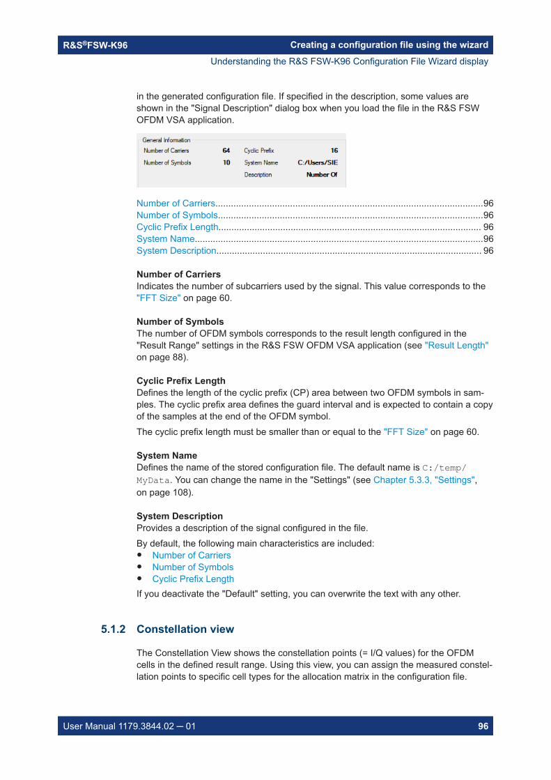
Creating a configuration file using the wizardR&S®FSW-K96
96User Manual 1179.3844.02 ─ 01
in the generated configuration file. If specified in the description, some values areshown in the "Signal Description" dialog box when you load the file in the R&S FSWOFDM VSA application.
Number of Carriers........................................................................................................96Number of Symbols.......................................................................................................96Cyclic Prefix Length...................................................................................................... 96System Name................................................................................................................96System Description....................................................................................................... 96
Number of CarriersIndicates the number of subcarriers used by the signal. This value corresponds to the"FFT Size" on page 60.
Number of SymbolsThe number of OFDM symbols corresponds to the result length configured in the"Result Range" settings in the R&S FSW OFDM VSA application (see "Result Length"on page 88).
Cyclic Prefix LengthDefines the length of the cyclic prefix (CP) area between two OFDM symbols in sam-ples. The cyclic prefix area defines the guard interval and is expected to contain a copyof the samples at the end of the OFDM symbol.The cyclic prefix length must be smaller than or equal to the "FFT Size" on page 60.
System NameDefines the name of the stored configuration file. The default name is C:/temp/MyData. You can change the name in the "Settings" (see Chapter 5.3.3, "Settings",on page 108).
System DescriptionProvides a description of the signal configured in the file.By default, the following main characteristics are included:● Number of Carriers● Number of Symbols● Cyclic Prefix LengthIf you deactivate the "Default" setting, you can overwrite the text with any other.
5.1.2 Constellation view
The Constellation View shows the constellation points (= I/Q values) for the OFDMcells in the defined result range. Using this view, you can assign the measured constel-lation points to specific cell types for the allocation matrix in the configuration file.
Understanding the R&S FSW-K96 Configuration File Wizard display

Creating a configuration file using the wizardR&S®FSW-K96
97User Manual 1179.3844.02 ─ 01
Figure 5-2: Constellation View
Selection toolSets the cursor action to selection mode. All cells in the selection area are highlightedin color. The Selection Mode / Zoom Mode indicator shows which color is used. Anysubsequent functions are applied to the selected cells.Click in the diagram and move the cursor, holding the mouse button, to display a dot-ted rectangle and define the selection area.Press the [Shift] key and click in the diagram to extend the selection to neighboringsymbols.Press the [CTRL] key and click in the diagram to add further (non-neighboring) pointsto the existing selection. Click the same points again to deselect them.
ZoomSets the cursor action to zoom mode. Click in the diagram and move the cursor, hold-ing the mouse button, to display a rectangle and define the zoom area. The zoomedarea is enlarged in the display. Repeat the action to zoom in further.The Selection Mode / Zoom Mode indicator above the diagram shows that zoom modeis active.To change the cursor function and stop zooming, select Selection tool.
Zoom OffDisplays the diagram in its original size.
Understanding the R&S FSW-K96 Configuration File Wizard display

Creating a configuration file using the wizardR&S®FSW-K96
98User Manual 1179.3844.02 ─ 01
Note that this function does not change the cursor function. To change the cursor func-tion and stop zooming, select Selection tool.The Selection Mode / Zoom Mode indicator above the diagram shows that zoom modeis active.
Selection Mode / Zoom Mode indicatorIndicates whether the current cursor action is to select cells (selection mode), or todefine the zoom area. In selection mode, the color used to highlight selected cells isindicated.
Show non-allocated constellation pointsDisplays or hides the constellation points not yet allocated to a cell type in the Constel-lation View.
Show allocated constellation pointsDisplays or hides the constellation points already allocated to a cell type in the Constel-lation View.
5.1.3 Matrix view
The Matrix View displays two different diagrams of the measured symbols (y-axis) vscarriers (x-axis).● Power vs Symbol x Carrier diagram
Shows a colored rectangle (= OFDM cell) for each symbol and carrier, with a differ-ent color for each measured power range. Thus, you can easily identify symbolswith a similar power value, which therefore most likely belong to the same cell type.
Understanding the R&S FSW-K96 Configuration File Wizard display

Creating a configuration file using the wizardR&S®FSW-K96
99User Manual 1179.3844.02 ─ 01
Figure 5-3: Matrix view with Power vs Symbol x Carrier diagram
Either a colored or a black-and-white (gray shades) power indication is available(see Black and white color map / Colored color map). The darker the color, thelower the power of the corresponding OFDM cell.
● Allocation MatrixShows a colored point for each allocated symbol and carrier, with a different colorfor each cell type.
Understanding the R&S FSW-K96 Configuration File Wizard display

Creating a configuration file using the wizardR&S®FSW-K96
100User Manual 1179.3844.02 ─ 01
Figure 5-4: Matrix view with Allocation Matrix
Optionally, the selected symbols can be highlighted in the matrix.
Similarly to the Constellation View, you can also select cells in the Matrix View toassign them to specific cell types.
Further zoom and selection functions are provided in the context-menu for the diagram(right-click in the diagram).
Black and white color map.......................................................................................... 100Colored color map.......................................................................................................101Highlight selected cells................................................................................................101Selection Mode / Zoom Mode indicator.......................................................................101Selection tool...............................................................................................................101Zoom........................................................................................................................... 101Zoom Off..................................................................................................................... 101Select Symbol / Select Carrier (context-menu)........................................................... 101Select Specific Symbol / Select Specific Carrier (context-menu)................................101Select Symbol/Carrier Range (context-menu)............................................................ 101Deselect All (context-menu)........................................................................................ 102Extract Symbols (context-menu)................................................................................. 102
Black and white color mapThe different modulation types in the Power vs Symbol x Carrier diagram are displayedin different shades of black, white, and gray. The lighter the shade of gray, the higherthe power level in the OFDM cell.
Understanding the R&S FSW-K96 Configuration File Wizard display

Creating a configuration file using the wizardR&S®FSW-K96
101User Manual 1179.3844.02 ─ 01
Colored color mapThe different modulation types in the Power vs Symbol x Carrier diagram are displayedin different colors. The used colors are indicated in the legend above the diagram.
Highlight selected cellsThe cells in the area selected by the Selection tool are highlighted in the AllocationMatrix.
Selection Mode / Zoom Mode indicatorIndicates whether the current cursor action is to select cells (selection mode), or todefine the zoom area. In selection mode, the color used to highlight selected cells isindicated.
Selection toolSets the cursor action to selection mode. All cells in the selection area are highlightedin color. The Selection Mode / Zoom Mode indicator shows which color is used. Anysubsequent functions are applied to the selected cells.Click in the diagram and move the cursor, holding the mouse button, to display a dot-ted rectangle and define the selection area.Press the [Shift] key and click in the diagram to extend the selection to neighboringsymbols.Press the [CTRL] key and click in the diagram to add further (non-neighboring) pointsto the existing selection. Click the same points again to deselect them.
ZoomSets the cursor action to zoom mode. Click in the diagram and move the cursor, hold-ing the mouse button, to display a rectangle and define the zoom area. The zoomedarea is enlarged in the display. Repeat the action to zoom in further.The Selection Mode / Zoom Mode indicator above the diagram shows that zoom modeis active.To change the cursor function and stop zooming, select Selection tool.
Zoom OffDisplays the diagram in its original size.Note that this function does not change the cursor function. To change the cursor func-tion and stop zooming, select Selection tool.The Selection Mode / Zoom Mode indicator above the diagram shows that zoom modeis active.
Select Symbol / Select Carrier (context-menu)Selects the symbol or carrier at the current cursor position.
Select Specific Symbol / Select Specific Carrier (context-menu)Opens an input field to enter a specific symbol or carrier number for selection.
Select Symbol/Carrier Range (context-menu)Opens a dialog box to define a start and stop symbol or carrier number of a range forselection.
Understanding the R&S FSW-K96 Configuration File Wizard display

Creating a configuration file using the wizardR&S®FSW-K96
102User Manual 1179.3844.02 ─ 01
Deselect All (context-menu)Deselects all currently selected symbols or carriers.
Extract Symbols (context-menu)Extracts a range of symbols from the imported signal for further analysis.Note: To restore discarded symbols for analysis, you must re-import the signal.This function is identical to Chapter 5.2.2, "Step 2: (Optional:) adjusting the analysisregion", on page 103.
5.2 Configuration steps
The wizard guides you through the process of creating a configuration file. The pro-gress bar (see Figure 5-1) indicates which step you are currently working on. Whenyou have completed all required steps, you will have created a configuration file thatcan be imported to the R&S FSW OFDM VSA application for signal analysis.
● Step 1: (Optional:) importing existing files.............................................................102● Step 2: (Optional:) adjusting the analysis region...................................................103● Step 3: synchronizing the measured data.............................................................104● Step 4: adjusting the gain......................................................................................104● Steps 5 + 6: allocating signal components............................................................105● Step 7: storing results........................................................................................... 107
5.2.1 Step 1: (Optional:) importing existing files
The wizard requires demodulated data as input. When you open the wizard directlyfrom the R&S FSW OFDM VSA application, the demodulated data from the input sig-nal is stored in a .K96_wizv file internally. The wizard automatically loads this filewhen it is started and you start with step 2.
If a configuration file already exists, you can load it to the wizard and use it to create anew one.
To import an existing configuration file
1. Select step 1 in the progress bar ("Step-by-Step").
Configuration steps

Creating a configuration file using the wizardR&S®FSW-K96
103User Manual 1179.3844.02 ─ 01
2. Select the .K96_wizv file to load.
The constellation diagram and allocation matrix are updated according to thestored data.
5.2.2 Step 2: (Optional:) adjusting the analysis region
By default, the result range configured in the R&S FSW OFDM VSA application definesthe number of symbols displayed in the Constellation View. If the result range was cor-rectly configured to comprise exactly one frame, you do not need to adjust the analysisregion.
If necessary, you can restrict the analysis region.
Example: The result range in Figure 5-5 contains 4 bursts, indicated by green bars. To configurethe configuration file using the wizard, only one burst is required. Thus, you can extractthe symbols for one burst to be used as the analysis region.
Figure 5-5: Sample result range with multiple bursts
To restrict the analysis region
1. Select step 2 in the progress bar ("Step-by-Step").
Configuration steps
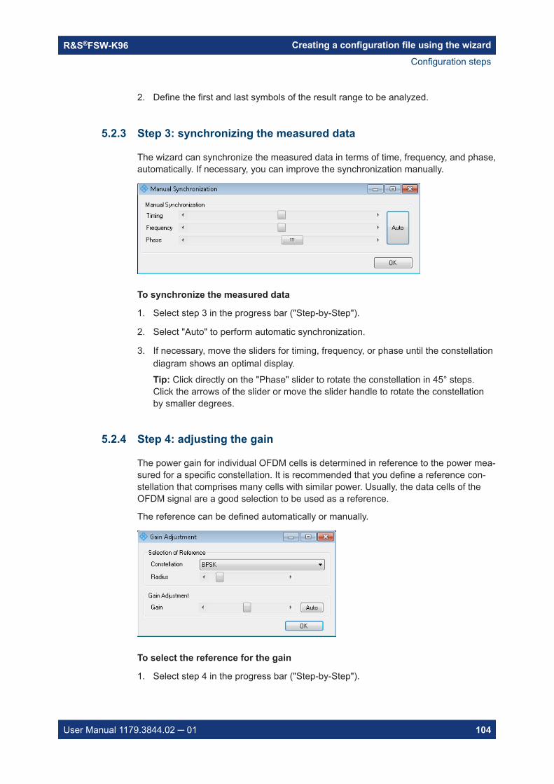
Creating a configuration file using the wizardR&S®FSW-K96
104User Manual 1179.3844.02 ─ 01
2. Define the first and last symbols of the result range to be analyzed.
5.2.3 Step 3: synchronizing the measured data
The wizard can synchronize the measured data in terms of time, frequency, and phase,automatically. If necessary, you can improve the synchronization manually.
To synchronize the measured data
1. Select step 3 in the progress bar ("Step-by-Step").
2. Select "Auto" to perform automatic synchronization.
3. If necessary, move the sliders for timing, frequency, or phase until the constellationdiagram shows an optimal display.
Tip: Click directly on the "Phase" slider to rotate the constellation in 45° steps.Click the arrows of the slider or move the slider handle to rotate the constellationby smaller degrees.
5.2.4 Step 4: adjusting the gain
The power gain for individual OFDM cells is determined in reference to the power mea-sured for a specific constellation. It is recommended that you define a reference con-stellation that comprises many cells with similar power. Usually, the data cells of theOFDM signal are a good selection to be used as a reference.
The reference can be defined automatically or manually.
To select the reference for the gain
1. Select step 4 in the progress bar ("Step-by-Step").
Configuration steps

Creating a configuration file using the wizardR&S®FSW-K96
105User Manual 1179.3844.02 ─ 01
2. Select the constellation type to use as a reference.
3. The "Radius" defines the area around the constellation point used to detect thesymbol and calculate the power of the symbol. As a rule, define the radius suchthat neighboring constellation markers do not overlap.
The currently used radius is indicated by a circle around the ideal constellationpoints in the Constellation View.
To adjust the gain
1. Select "Auto" to perform a gain estimation based on the power measured in theselected constellation type.
2. To increase the reference gain, move the slider to the right.To reduce the reference gain, move the slider to the left.
3. Select "OK" to define the measured power of the selected cells as the referencepower for gain settings of other cells.
5.2.5 Steps 5 + 6: allocating signal components
In this step, you must configure the main characteristics of each OFDM cell. To do so,you must select the OFDM cells that belong to a specific cell type, configure their char-acteristics, and then allocate them. The result is an allocation matrix that contains infor-mation for each OFDM cell of the current OFDM frame.
How to allocate the individual signal components
The characteristics that cells of the same type have in common are referred to as"Constellation Markers".
Select constellation markers that match your demodulated constellation, or a subset ofyour demodulated constellation. If you cannot see a clear constellation, improve thesynchronization as described in Chapter 5.2.3, "Step 3: synchronizing the measureddata", on page 104.
1. Select step 5 in the progress bar ("Step-by-Step").
Note: Steps 5 and 6 use the same display, therefore it is not necessary to switchfrom step 5 to 6.
2. The selection from Step 4: adjusting the gain is maintained, so you can allocate thecell type used for gain adjustment first.
a) Optionally, edit the name of the cell type, which is used for the legend of theAllocation Matrix. By default, the cell type and modulation are used.
Configuration steps

Creating a configuration file using the wizardR&S®FSW-K96
106User Manual 1179.3844.02 ─ 01
b) Select the checkmark and confirm the message to allocate the selected cellsto the selected cell type.
3. For all other cell types, in the Constellation View, select the modulation type.
The symbols with the selected modulation are highlighted.
4. For "Don't care" cells, for which no characteristic modulation applies, define or editthe selection manually using the Selection tool.
5. Another characteristic stored for each cell is the gain value. By default, the refer-ence power defined in Step 4: adjusting the gain is assumed. Thus, a "Boosting"factor of 1.000 - relative to the reference power - is defined. For cells with differentgain values, define a different boosting factor to be applied to the reference power.
● To determine the required boosting automatically from the constellation points,select "Auto".
● If you know the required factor, click the boosting value and enter the valuedirectly.
Note: The more accurate the boosting is defined, the more accurate the EVMresults in the R&S FSW OFDM VSA application.
6. The "Radius" defines the area around the ideal constellation point used to detectthe measured constellation points that correspond to the currently selected constel-lation type. As a rule, select the radius such that the circles around the ideal con-stellation points do not overlap.If necessary, adapt the radius around the ideal constellation points to include alland only constellation points that belong to the selected constellation type.
7. In the Constellation View, in the "Allocation" area, select the cell type of theselected OFDM cells, for example "Pilot" or "Data".
8. Optionally, edit the name of the cell type, which is used for the legend of the Alloca-tion Matrix. By default, the cell type and modulation are used.
9. Select the checkmark and confirm the message to allocate the selected cells to theselected cell type.
The cells are indicated in the color shown in the legend above the AllocationMatrix. The cells are no longer displayed if you selected only Show non-allocatedconstellation points in the Constellation View.
10. If necessary, you can revert the last allocation.
The allocated OFDM cells are indicated as non-allocated (but still selected).
11. Repeat these steps until all OFDM have been allocated. When the last cell typehas been allocated, a message is displayed asking you to store the results.
Tip: In the Constellation View, select Show non-allocated constellation pointsand deselect "Show allocated constellation points" on page 98 to see which cellsare still missing in the Allocation Matrix.
Configuration steps

Creating a configuration file using the wizardR&S®FSW-K96
107User Manual 1179.3844.02 ─ 01
5.2.6 Step 7: storing results
When you have allocated all constellation points in the Constellation View to a cell typeand configured all other settings as required, store the results to a file. The resultingconfiguration file can then be used for analysis in the R&S FSW OFDM VSA applica-tion.
To store a configuration file
1. At the end of Steps 5 + 6: allocating signal components, when all OFDM cells havebeen allocated, you are automatically asked if you want to store the configurationfile.At any other point in the configuration process, select step 7 in the progress bar("Step-by-Step"), or select the "File" > "Save Configuration File" menu item.
2. Select a filename and storage location for the configuration file.
3. Select "Save".
5.3 Reference of wizard menu functions
The following functions are provided in the menus of the configuration file wizard.
● File functions.........................................................................................................107● Edit functions.........................................................................................................108● Settings................................................................................................................. 108● Help.......................................................................................................................110
5.3.1 File functions
New............................................................................................................................. 107Import Data from R&S OFDM VSA............................................................................. 107Load Configuration File............................................................................................... 108Save Configuration File...............................................................................................108Exit.............................................................................................................................. 108
NewCreates a new, empty configuration file. This function is similar to a preset function.Any information from the input signal in the R&S FSW OFDM VSA application is nolonger available in the wizard. Load existing signal or configuration data to continue.See "Import Data from R&S OFDM VSA" on page 107 and "Load Configuration File"on page 108.
Import Data from R&S OFDM VSAOpens a file selection dialog box to import I/Q data from an existing .K96_wizv file(created by the R&S FSW OFDM VSA application).
Reference of wizard menu functions

Creating a configuration file using the wizardR&S®FSW-K96
108User Manual 1179.3844.02 ─ 01
Load Configuration FileOpens a file selection dialog box to load an existing .xml configuration file, for exam-ple as the basis for a similar configuration.
Save Configuration FileOpens a file selection dialog box to save the current configuration to an .xml file.
This function is identical to Chapter 5.2.6, "Step 7: storing results", on page 107.Note: At the end of Steps 5 + 6: allocating signal components, when all symbols havebeen allocated, you are automatically asked if you want to store the configuration file.
ExitCloses the wizard without a confirmation. Use Save Configuration File to store yourcurrent configuration before exiting.
5.3.2 Edit functions
Reset All Allocations................................................................................................... 108Undo Last Allocation................................................................................................... 108Extract Symbols (context-menu)................................................................................. 108Shift Left by 1 Carrier / Shift Right by 1 Carrier...........................................................108
Reset All AllocationsRemoves all applied allocations. All cells are indicated as non-allocated.
Undo Last AllocationReverts the most recently applied allocation. The allocated cells are indicated as non-allocated (but still selected).This function is identical to using the icon in the Constellation View.
Extract Symbols (context-menu)Extracts a range of symbols from the imported signal for further analysis.Note: To restore discarded symbols for analysis, you must re-import the signal.This function is identical to Chapter 5.2.2, "Step 2: (Optional:) adjusting the analysisregion", on page 103.
Shift Left by 1 Carrier / Shift Right by 1 CarrierShifts the carrier information for all symbols by one carrier. Shifting is useful to com-pensate for a frequency offset that could not be corrected by the automatic synchroni-zation function.
5.3.3 Settings
System Name..............................................................................................................109System Description..................................................................................................... 109Cyclic Prefix Length.................................................................................................... 109Preamble.....................................................................................................................109
Reference of wizard menu functions

Creating a configuration file using the wizardR&S®FSW-K96
109User Manual 1179.3844.02 ─ 01
└ Set Preamble................................................................................................ 109└ Block Length................................................................................................. 109└ Frame Start Offset.........................................................................................110
Cyclic Delay Diversity..................................................................................................110
System NameDefines the name of the stored configuration file. The default name is C:/temp/MyData. You can change the name in the "Settings" (see Chapter 5.3.3, "Settings",on page 108).
System DescriptionProvides a description of the signal configured in the file.By default, the following main characteristics are included:● Number of Carriers● Number of Symbols● Cyclic Prefix LengthIf you deactivate the "Default" setting, you can overwrite the text with any other.
Cyclic Prefix LengthDefines the length of the cyclic prefix (CP) area between two OFDM symbols in sam-ples. The cyclic prefix area defines the guard interval and is expected to contain a copyof the samples at the end of the OFDM symbol.The cyclic prefix length must be smaller than or equal to the "FFT Size" on page 60.
PreamblePreamble symbol characteristics can be stored in the configuration file. These settingscorrespond to the settings in the "Signal Description" dialog in the R&S FSW OFDMVSA application (see Chapter 4.2, "Signal description", on page 58). The informationcan be used by the R&S FSW OFDM VSA application, for example for synchroniza-tion.
Set Preamble ← PreambleIf activated, the defined preamble symbol characteristics are stored in the configurationfile.
Block Length ← PreambleSpecifies the length of one data block within the repetitive preamble as a number ofsamples.
Reference of wizard menu functions

Creating a configuration file using the wizardR&S®FSW-K96
110User Manual 1179.3844.02 ─ 01
Frame Start Offset ← PreambleSpecifies the time offset from the preamble start to the actual frame start as a numberof samples.
Cyclic Delay DiversityDefines a cyclic shift of the FFT values for each OFDM symbol before adding the cyclicprefix.
5.3.4 Help
Provides context-sensitive help on the configuration process, according to the currentlyselected process step.
5.4 Example: creating a configuration file from an inputsignal
For this example, we use the I/Q data in the demo fileC:\R_S\INSTR\USER\demo\OFDM-VSA\WlanA_64QAM.iq.tar provided with theR&S FSW software.
The following signal parameters are already known:● FFT size (= number of subcarriers): 64 samples● Cyclic prefix length: 16 samples● OFDM system sample rate: 20 MHz● Pilot modulation: QPSK + 45°QPSK● Data modulation: 64QAM + BPSK
1. Define the basic signal parameters so the R&S FSW OFDM VSA application candemodulate the data.
a) Select the "Meas Setup > Signal Description" menu item.
● Set "FFT Size" = 64.● Set "Cyclic Prefix Length" = 16.
b) Select the "Meas Setup > Data Acquisition" menu item.
● Set "Sample Rate" = 20 MHz.
2. Select the I/Q data file to be used as input:
a) Select "Input/Frontend" > "Input Source" > "I/Q file" > "Select file".b) Select C:\R_S\INSTR\USER\demo\OFDM-VSA\WlanA_64QAM.iq.tar.c) Set the state of the I/Q file input to "On".
The Magnitude Capture display shows the bursted signal.
Example: creating a configuration file from an input signal

Creating a configuration file using the wizardR&S®FSW-K96
111User Manual 1179.3844.02 ─ 01
3. The green bar in the Magnitude Capture diagram does not cover an entire frame.Increase the result range to include all symbols of a frame.
a) Select the "Meas Setup > Result Range" menu item.
● Set "Result Length" = 100.
The data is now demodulated correctly and can be used as input for a new config-uration file.
4. In the "Signal Description" dialog box, select "Create New Configuration File".
5. Since it is a bursted signal and the result range is large enough, the analysis rangecorresponds to exactly one frame. We can start directly with step 3, synchroniza-tion.Our constellation diagram is slightly rotated and generally does not show an idealconstellation, so we must improve the synchronization settings.
Example: creating a configuration file from an input signal

Creating a configuration file using the wizardR&S®FSW-K96
112User Manual 1179.3844.02 ─ 01
Figure 5-6: Constellation diagram for loaded WLAN signal data
Select step 3 in the progress bar.
a) Select "Auto" to perform automatic synchronization.
Example: creating a configuration file from an input signal

Creating a configuration file using the wizardR&S®FSW-K96
113User Manual 1179.3844.02 ─ 01
b) If necessary, move the sliders for timing, frequency, or phase until the constel-lation diagram shows an optimal display.
Figure 5-7: Constellation diagram after automatic synchronization
6. The reference constellation for the gain calculation is best defined by the data cellsin this signal, which use a 64QAM modulation.Select step 4 in the progress bar.
a) In the "Gain Adjustment" dialog box, select "Constellation" = "64QAM".
Example: creating a configuration file from an input signal
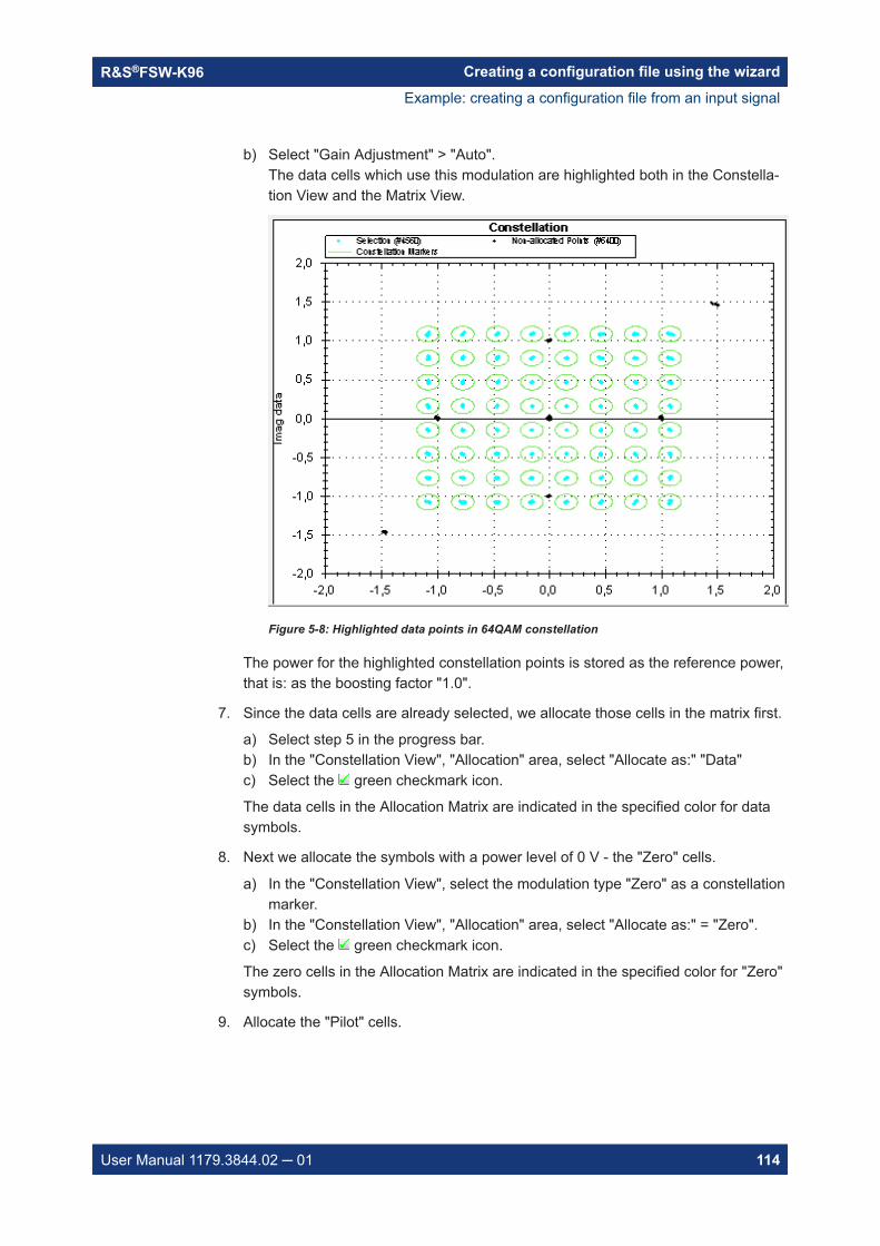
Creating a configuration file using the wizardR&S®FSW-K96
114User Manual 1179.3844.02 ─ 01
b) Select "Gain Adjustment" > "Auto".The data cells which use this modulation are highlighted both in the Constella-tion View and the Matrix View.
Figure 5-8: Highlighted data points in 64QAM constellation
The power for the highlighted constellation points is stored as the reference power,that is: as the boosting factor "1.0".
7. Since the data cells are already selected, we allocate those cells in the matrix first.
a) Select step 5 in the progress bar.b) In the "Constellation View", "Allocation" area, select "Allocate as:" "Data"c) Select the green checkmark icon.
The data cells in the Allocation Matrix are indicated in the specified color for datasymbols.
8. Next we allocate the symbols with a power level of 0 V - the "Zero" cells.
a) In the "Constellation View", select the modulation type "Zero" as a constellationmarker.
b) In the "Constellation View", "Allocation" area, select "Allocate as:" = "Zero".c) Select the green checkmark icon.
The zero cells in the Allocation Matrix are indicated in the specified color for "Zero"symbols.
9. Allocate the "Pilot" cells.
Example: creating a configuration file from an input signal

Creating a configuration file using the wizardR&S®FSW-K96
115User Manual 1179.3844.02 ─ 01
a) In the "Constellation View", select the modulation type "QPSK" as a constella-tion marker.
Figure 5-9: Symbols with QPSK constellation
Although we know some of the pilots use QPSK modulation, none of the sym-bols are highlighted. Possibly a boosting factor was applied.
Example: creating a configuration file from an input signal

Creating a configuration file using the wizardR&S®FSW-K96
116User Manual 1179.3844.02 ─ 01
b) Select the "Boosting" - "Auto" function.A boosting of 2.079 is detected and applied to the symbols. Now some of thesymbols are highlighted.
Figure 5-10: Symbols with QPSK modulation and applied boosting
c) In the "Constellation View", "Allocation" area, select "Allocate as:" "Pilots".d) Select the green checkmark icon.
The pilot cells in the Allocation Matrix are indicated in the specified color for "Pilot"symbols, and the selected cells are stored with a boosting factor of 2.079.
10. Some of the remaining cells are data cells with a BPSK modulation.
a) In the "Constellation View", select the modulation type "BPSK" as a constella-tion marker.
b) In the "Constellation View", "Allocation" area, select "Allocate as:" = "Data".c) Select the green checkmark icon.
11. The last remaining cells are pilot cells with a 45°QPSK modulation.
a) In the "Constellation View", select the modulation type "45°QPSK" as a constel-lation marker.
Example: creating a configuration file from an input signal

Creating a configuration file using the wizardR&S®FSW-K96
117User Manual 1179.3844.02 ─ 01
b) In the "Constellation View", "Allocation" area, select "Allocate as:" = "Pilot".c) Select the green checkmark icon.
A message is displayed informing you that all symbols are allocated.
12. Store the configuration file.Select step 7 in the progress bar.
a) Enter the filename and storage location for the configuration file:C:\R_S\INSTR\USER\demo\OFDM-VSA\MyWlanA_64QAM.xml
13. Close the wizard.
Now you can load the configuration file in the R&S FSW OFDM VSA application.
Example: creating a configuration file from an input signal

Analyzing OFDM VSA vector signalsR&S®FSW-K96
118User Manual 1179.3844.02 ─ 01
6 Analyzing OFDM VSA vector signalsAccess: "Meas Config" > "Result Config"
General result analysis settings concerning the trace, markers, windows etc. can beconfigured. They are identical to the analysis functions in the base unit except for thespecial window functions.
● Result configuration...............................................................................................118● Table configuration................................................................................................120● Units......................................................................................................................121● Y-scaling................................................................................................................121● Markers................................................................................................................. 123● Trace / data export configuration.......................................................................... 128
6.1 Result configuration
Access: "Meas Config" > "Result Config" > "Result Configuration" tab
Some result displays provide further settings.
Normalize EVM to........................................................................................................119Frame Averaging.........................................................................................................119Constellation Display - Modulation Type..................................................................... 119Constellation Display - Modulation.............................................................................. 119Constellation Display - Symbol................................................................................... 120Constellation Display - Carrier.................................................................................... 120Constellation Display - Point Size............................................................................... 120
Result configuration

Analyzing OFDM VSA vector signalsR&S®FSW-K96
119User Manual 1179.3844.02 ─ 01
Normalize EVM toSpecifies the OFDM cells which are averaged to get the reference magnitude for EVMnormalization.(See Chapter A.1, "Error vector magnitude (EVM)", on page 249 for details.)"RMS Pilots &Data"
RMS value of the pilot and data cells
"RMS Data" RMS value of the data cells"RMS Pilots" RMS value of the pilot cells"Peak Pilots &Data"
Peak value of the pilot and data cells
"Peak Data" Peak value of the data cells"Peak Pilots" Peak value of the pilot cells"None" Normalization is turned offRemote command: [SENSe:]DEMod:EVMCalc:NORMalize on page 184
Frame AveragingSpecifies the method of averaging over multiple OFDM frames in one capture bufferused to get the mean EVM values in the result list.
Frame averaging Averaged EVM over N frames
Mean square
1
0
21 N
iiEVM
N
RMS
1
0
1 N
iiEVM
N
Mean square averaging is consistent with the EVM calculation within one frame. How-ever, some standards, e.g. 802.11a, require RMS averaging.Remote command: [SENSe:]DEMod:EVMCalc:FAVerage on page 184
Constellation Display - Modulation TypeThe constellation diagram includes only symbols for the selected modulation types.The selected modulation types are indicated in the constellation diagram for reference.Remote command: CONFigure:FILTer<n>:MODulation:TYPE on page 185
Constellation Display - ModulationThe constellation diagram includes only symbols with the selected modulation.Remote command: CONFigure:FILTer<n>:MODulation on page 185
Result configuration

Analyzing OFDM VSA vector signalsR&S®FSW-K96
120User Manual 1179.3844.02 ─ 01
Constellation Display - SymbolThe constellation diagram includes all or only the specified symbol number. The firstsymbol number is 0.Remote command: CONFigure:FILTer<n>:SYMBol on page 186
Constellation Display - CarrierThe constellation diagram includes symbols for all or only for the specified carrier num-ber.The range of valid carrier numbers is:[- FFT Size/2, +FFT Size/2]Remote command: CONFigure:FILTer<n>:CARRier on page 185
Constellation Display - Point SizeDefines the size of the individual points in a constellation diagram.
6.2 Table configuration
Access: "Meas Config" > "Result Config" > "Table Config"
During each measurement, many characteristic signal parameters are determined.Select the parameters to be included in the table. For a description of the individualparameters, see Chapter 2.1, "OFDM VSA parameters", on page 9.
Table configuration

Analyzing OFDM VSA vector signalsR&S®FSW-K96
121User Manual 1179.3844.02 ─ 01
6.3 Units
Access: "Meas Config" > "Result Config" > "Units" tab
For some result configurations, the unit of the displayed values can be configured.
Remote command:
EVM: UNIT:EVM on page 189
Symbol axes: UNIT:SAXes on page 190
Carrier axes: UNIT:CAXes on page 189
Magnitude Capture: UNIT:TAXes on page 191
Power Spectrum: UNIT:FAXes on page 190
Impulse Response: UNIT:IRESponse on page 190
6.4 Y-scaling
Access: "Meas Config" > "Result Config" > "Y Scaling" tab
The scaling for the vertical axis is highly configurable, using either absolute or relativevalues. Note that scaling settings are window-specific and not available for all resultdisplays.
Y-scaling
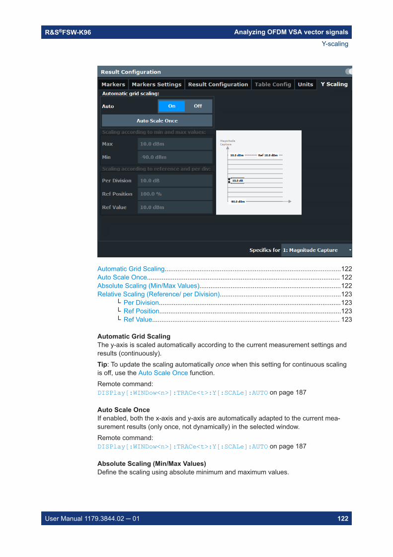
Analyzing OFDM VSA vector signalsR&S®FSW-K96
122User Manual 1179.3844.02 ─ 01
Automatic Grid Scaling................................................................................................122Auto Scale Once......................................................................................................... 122Absolute Scaling (Min/Max Values).............................................................................122Relative Scaling (Reference/ per Division)..................................................................123
└ Per Division...................................................................................................123└ Ref Position...................................................................................................123└ Ref Value...................................................................................................... 123
Automatic Grid ScalingThe y-axis is scaled automatically according to the current measurement settings andresults (continuously).Tip: To update the scaling automatically once when this setting for continuous scalingis off, use the Auto Scale Once function.Remote command: DISPlay[:WINDow<n>]:TRACe<t>:Y[:SCALe]:AUTO on page 187
Auto Scale OnceIf enabled, both the x-axis and y-axis are automatically adapted to the current mea-surement results (only once, not dynamically) in the selected window.Remote command: DISPlay[:WINDow<n>]:TRACe<t>:Y[:SCALe]:AUTO on page 187
Absolute Scaling (Min/Max Values)Define the scaling using absolute minimum and maximum values.
Y-scaling

Analyzing OFDM VSA vector signalsR&S®FSW-K96
123User Manual 1179.3844.02 ─ 01
Remote command: DISPlay[:WINDow<n>]:TRACe<t>:Y[:SCALe]:MAXimum on page 187DISPlay[:WINDow<n>]:TRACe<t>:Y[:SCALe]:MINimum on page 187
Relative Scaling (Reference/ per Division)Define the scaling relative to a reference value, with a specified value range per divi-sion.
Per Division ← Relative Scaling (Reference/ per Division)Defines the value range to be displayed per division of the diagram (1/10 of totalrange).Note: The value defined per division refers to the default display of 10 divisions on they-axis. If fewer divisions are displayed (e.g. because the window is reduced in height),the range per division is increased to display the same result range in the smaller win-dow. In this case, the per division value does not correspond to the actual display.Remote command: DISPlay[:WINDow<n>]:TRACe<t>:Y[:SCALe]:PDIVision on page 188
Ref Position ← Relative Scaling (Reference/ per Division)Defines the position of the reference value in percent of the total y-axis range.Remote command: DISPlay[:WINDow<n>]:TRACe<t>:Y[:SCALe]:RPOSition on page 188
Ref Value ← Relative Scaling (Reference/ per Division)Defines the reference value to be displayed at the specified reference position.Remote command: DISPlay[:WINDow<n>][:SUBWindow<w>]:TRACe<t>:Y[:SCALe]:RVALueon page 188
6.5 Markers
Access: "Meas Config" > "Result Config" > "Markers" tab
Or: "Marker"
Markers help you analyze your measurement results by determining particular valuesin the diagram. Thus, you can extract numeric values from a graphical display.
Markers in 3-dimensional diagramsSome diagrams have a third dimension - in addition to the x-axis and y-axis they showa third dimension (z-dimension) of results using different colors. For such diagrams,you must define the position of the marker both in the x-dimension and in the y-dimen-sion to obtain the results in the z-dimension.
Markers

Analyzing OFDM VSA vector signalsR&S®FSW-K96
124User Manual 1179.3844.02 ─ 01
Markers in the Constellation View and Allocation MatrixUsing markers in a Constellation View you can detect individual constellation points fora specific symbol or carrier. When you activate a marker in the Constellation View, itsposition is defined by the symbol and carrier number the point belongs to. However,the marker result indicates the I and Q values of the point.Similarly, you can define markers in an Allocation Matrix by selecting the symbol andcarrier number.Using markers in the Constellation View and Allocation Matrix, you can scroll throughthe points for a specific carrier, for example. Activate a marker, then use the rotaryknob or mouse wheel to move the marker from one symbol to the next.
● Individual marker settings..................................................................................... 124● General marker settings........................................................................................126● Marker positioning functions................................................................................. 127
6.5.1 Individual marker settings
Access: "Meas Config" > "Result Config" > "Markers" tab
In OFDM VSA evaluations, up to 16 markers can be activated in each diagram at anytime.
Selected Marker.......................................................................................................... 125Marker State................................................................................................................125X-Value........................................................................................................................125
Markers
Analyzing OFDM VSA vector signalsR&S®FSW-K96
125User Manual 1179.3844.02 ─ 01
Y-Value........................................................................................................................ 125Marker Type................................................................................................................ 125Reference Marker....................................................................................................... 126Linking to Another Marker........................................................................................... 126Assigning the Marker to a Trace................................................................................. 126All Markers Off.............................................................................................................126
Selected MarkerMarker name. The marker which is currently selected for editing is highlighted orange.Remote command: Marker selected via suffix <m> in remote commands.
Marker StateActivates or deactivates the marker in the diagram.Remote command: CALCulate<n>:MARKer<m>[:STATe] on page 193CALCulate<n>:DELTamarker<m>[:STATe] on page 195
X-ValueDefines the position of the marker on the x-axis.For the Constellation View, the position is defined by a symbol number.Remote command: CALCulate<n>:DELTamarker<m>:X on page 196CALCulate<n>:MARKer<m>:X on page 193
Y-ValueDefines the position of the marker on the y-axis for 3-dimensional diagrams.For the Constellation View, the position is defined by a carrier number.Remote command: CALCulate<n>:DELTamarker<m>:Y? on page 223CALCulate<n>:MARKer<m>:Y? on page 224
Marker TypeToggles the marker type.The type for marker 1 is always "Normal", the type for delta marker 1 is always "Delta".These types cannot be changed.Note: If normal marker 1 is the active marker, switching the "Mkr Type" activates anadditional delta marker 1. For any other marker, switching the marker type does notactivate an additional marker, it only switches the type of the selected marker."Normal" A normal marker indicates the absolute value at the defined position
in the diagram."Delta" A delta marker defines the value of the marker relative to the speci-
fied reference marker (marker 1 by default).Remote command: CALCulate<n>:MARKer<m>[:STATe] on page 193CALCulate<n>:DELTamarker<m>[:STATe] on page 195
Markers

Analyzing OFDM VSA vector signalsR&S®FSW-K96
126User Manual 1179.3844.02 ─ 01
Reference MarkerDefines a marker as the reference marker which is used to determine relative analysisresults (delta marker values).If the reference marker is deactivated, the delta marker referring to it is also deactiva-ted.Remote command: CALCulate<n>:DELTamarker<m>:MREFerence on page 195
Linking to Another MarkerLinks the current marker to the marker selected from the list of active markers. If the x-axis value of the initial marker is changed, the linked marker follows to the same posi-tion on the x-axis. Linking is off by default.Using this function you can set two markers on different traces to measure the differ-ence (e.g. between a max hold trace and a min hold trace or between a measurementand a reference trace).For linked delta markers, the x-value of the delta marker is 0 Hz by default. To create adelta marker in a fixed distance to another marker, define the distance as the x-valuefor the linked delta marker.Remote command: CALCulate<n>:MARKer<ms>:LINK:TO:MARKer<md> on page 192CALCulate<n>:DELTamarker<ms>:LINK:TO:MARKer<md> on page 194CALCulate<n>:DELTamarker<m>:LINK on page 194
Assigning the Marker to a TraceThe "Trace" setting assigns the selected marker to an active trace. The trace deter-mines which value the marker shows at the marker position. If the marker was previ-ously assigned to a different trace, the marker remains on the previous frequency ortime, but indicates the value of the new trace.If a trace is turned off, the assigned markers and marker functions are also deactiva-ted.Remote command: CALCulate<n>:MARKer<m>:TRACe on page 193
All Markers OffDeactivates all markers in one step.Remote command: CALCulate<n>:MARKer<m>:AOFF on page 192
6.5.2 General marker settings
Access: "Meas Config" > "Result Config" > "Marker Settings" tab
Or: "Marker" > "Marker Settings"
Markers
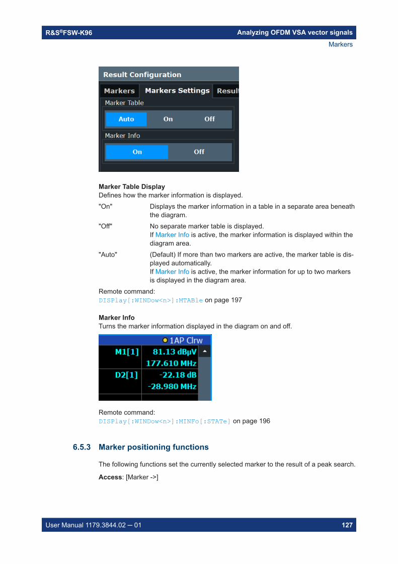
Analyzing OFDM VSA vector signalsR&S®FSW-K96
127User Manual 1179.3844.02 ─ 01
Marker Table DisplayDefines how the marker information is displayed."On" Displays the marker information in a table in a separate area beneath
the diagram."Off" No separate marker table is displayed.
If Marker Info is active, the marker information is displayed within thediagram area.
"Auto" (Default) If more than two markers are active, the marker table is dis-played automatically.If Marker Info is active, the marker information for up to two markersis displayed in the diagram area.
Remote command: DISPlay[:WINDow<n>]:MTABle on page 197
Marker InfoTurns the marker information displayed in the diagram on and off.
Remote command: DISPlay[:WINDow<n>]:MINFo[:STATe] on page 196
6.5.3 Marker positioning functions
The following functions set the currently selected marker to the result of a peak search.
Access: [Marker ->]
Markers

Analyzing OFDM VSA vector signalsR&S®FSW-K96
128User Manual 1179.3844.02 ─ 01
Peak Search................................................................................................................128Search Next Peak....................................................................................................... 128Search Minimum......................................................................................................... 128Search Next Minimum.................................................................................................128
Peak SearchSets the selected marker/delta marker to the maximum of the trace. If no marker isactive, marker 1 is activated.Remote command: CALCulate<n>:MARKer<m>:MAXimum[:PEAK] on page 201CALCulate<n>:DELTamarker<m>:MAXimum[:PEAK] on page 199
Search Next PeakSets the selected marker/delta marker to the next (lower) maximum of the assignedtrace. If no marker is active, marker 1 is activated.Remote command: CALCulate<n>:MARKer<m>:MAXimum:NEXT on page 200CALCulate<n>:MARKer<m>:MAXimum:RIGHt on page 201CALCulate<n>:MARKer<m>:MAXimum:LEFT on page 200CALCulate<n>:DELTamarker<m>:MAXimum:NEXT on page 198CALCulate<n>:DELTamarker<m>:MAXimum:RIGHt on page 199CALCulate<n>:DELTamarker<m>:MAXimum:LEFT on page 198
Search MinimumSets the selected marker/delta marker to the minimum of the trace. If no marker isactive, marker 1 is activated.Remote command: CALCulate<n>:MARKer<m>:MINimum[:PEAK] on page 202CALCulate<n>:DELTamarker<m>:MINimum[:PEAK] on page 199
Search Next MinimumSets the selected marker/delta marker to the next (higher) minimum of the selectedtrace. If no marker is active, marker 1 is activated.Remote command: CALCulate<n>:MARKer<m>:MINimum:NEXT on page 201CALCulate<n>:MARKer<m>:MINimum:LEFT on page 201CALCulate<n>:MARKer<m>:MINimum:RIGHt on page 202CALCulate<n>:DELTamarker<m>:MINimum:NEXT on page 199CALCulate<n>:DELTamarker<m>:MINimum:LEFT on page 199CALCulate<n>:DELTamarker<m>:MINimum:RIGHt on page 200
6.6 Trace / data export configuration
Access: "Save" > "Export" > "Trace Export Configuration"
Or: [TRACE] > "Trace Config" > "Trace / Data Export"
Trace / data export configuration

Analyzing OFDM VSA vector signalsR&S®FSW-K96
129User Manual 1179.3844.02 ─ 01
The standard data management functions (e.g. saving or loading instrument settings)that are available for all R&S FSW applications are not described here.See the R&S FSW base unit user manual for a description of the standard functions.
Export all Traces and all Table Results....................................................................... 129Include Instrument & Measurement Settings.............................................................. 129Export All Traces for Selected Graph..........................................................................129Trace to Export............................................................................................................130Decimal Separator...................................................................................................... 130Export Trace to ASCII File...........................................................................................130
Export all Traces and all Table ResultsSelects all displayed traces and result tables (e.g. Result Summary, marker table etc.)in the current application for export to an ASCII file.Alternatively, you can select one specific trace only for export (see Trace to Export).The results are output in the same order as they are displayed on the screen: windowby window, trace by trace, and table row by table row.Remote command: FORMat:DEXPort:TRACes on page 227
Include Instrument & Measurement SettingsIncludes additional instrument and measurement settings in the header of the exportfile for result data.Remote command: FORMat:DEXPort:HEADer on page 226
Export All Traces for Selected GraphIncludes all traces for the currently selected graphical result display in the export file.
Trace / data export configuration

Analyzing OFDM VSA vector signalsR&S®FSW-K96
130User Manual 1179.3844.02 ─ 01
Remote command: FORMat:DEXPort:GRAPh on page 226
Trace to ExportDefines an individual trace to be exported to a file.This setting is not available if Export all Traces and all Table Results is selected.
Decimal SeparatorDefines the decimal separator for floating-point numerals for the data export/importfiles. Evaluation programs require different separators in different languages.Remote command: FORMat:DEXPort:DSEParator on page 226
Export Trace to ASCII FileOpens a file selection dialog box and saves the selected trace in ASCII format (.dat)to the specified file and directory.The results are output in the same order as they are displayed on the screen: windowby window, trace by trace, and table row by table row.Note: Secure user mode.In secure user mode, settings that are stored on the instrument are stored to volatilememory, which is restricted to 256 MB. Thus, a "memory limit reached" error can occuralthough the hard disk indicates that storage space is still available.To store data permanently, select an external storage location such as a USB memorydevice.For details, see "Protecting Data Using the Secure User Mode" in the "Data Manage-ment" section of the R&S FSW base unit user manual.
Remote command: MMEMory:STORe<n>:TRACe on page 227
Trace / data export configuration

How to perform measurements in the R&S FSW OFDM VSA applicationR&S®FSW-K96
131User Manual 1179.3844.02 ─ 01
7 How to perform measurements in the R&SFSW OFDM VSA applicationThe following step-by-step instructions demonstrate how to perform measurementswith the R&S FSW OFDM VSA application.
The R&S FSW OFDM VSA application provides sample data and sample configurationfiles in the C:\R_S\INSTR\USER\demo\OFDM-VSA directory.
To perform an OFDM VSA measurement
1. Open a new channel or replace an existing one and select the R&S FSW OFDMVSA application.
2. Configure the input source to be used.
3. Select the "Overview" softkey to display the "Overview" for an OFDM VSA mea-surement.
4. Select the "Signal Description" button and configure the expected signal character-istics either manually or using a configuration file.
5. To use a configuration file:
a) If no configuration file is available yet, create one from the input signal asdescribed in Chapter 5, "Creating a configuration file using the wizard",on page 94.
b) Select "Load Config. File".c) Select the configuration file to use.
The file is loaded and "Use Configuration File" is automatically set to "Yes".
6. Select the "Input/Frontend" button to define the input signal's center frequency,amplitude and other basic settings.
7. Optionally, select the "Trigger" button and define a trigger for data acquisition, forexample an external trigger to start capturing data only when a useful signal istransmitted.
8. For bursted signals, select the "Burst Search" button and activate a burst search.
9. Select the "Data Acquisition" button and define how much and which data to cap-ture:
● "Capture Time" or "Capture length": the duration or number of samples to becapturedFor non-triggered ("Free run") measurements, be sure to capture at least twicethe number of samples per frame so you are sure to capture at least one entireframe.
How to perform measurements in the R&S FSW OFDM VSA applicationR&S®FSW-K96
132User Manual 1179.3844.02 ─ 01
● "Sample rate": the rate at which I/Q data is acquired (analysis bandwidth / 0.8);must also correspond to the OFDM system sample rate (<subcarrier_spacing>* <FFT_size>, see also "OFDM system sample rate" on page 32)
10. Select the "Result Range" button and define how many OFDM symbols are to beinterpreted as one frame.
11. To optimize the synchronization process, if necessary, select the "Sync/Demod"button and configure the synchronization and demodulation parameters.Which compensation and synchronization functions are allowed depends on thestandard defining the tests.
12. Select the "Configure Display" icon from the toolbar to add further result displaysfor the R&S FSW OFDM VSA application.
The measured data is stored in the capture buffer and can be analyzed.
Remote commands for the R&S FSW OFDM VSA applicationR&S®FSW-K96
133User Manual 1179.3844.02 ─ 01
8 Remote commands for the R&S FSWOFDM VSA applicationThe following commands are required to perform measurements in the R&S FSWOFDM VSA application in a remote environment.
It is assumed that the R&S FSW has already been set up for remote control in a net-work as described in the R&S FSW User Manual.
General R&S FSW Remote Commands
The application-independent remote commands for general tasks on the R&S FSW arealso available for R&S FSW OFDM VSA application and are described in theR&S FSW Base Software User Manual. In particular, this comprises the following func-tionality:● Managing Settings and Results● Setting Up the Instrument● Using the Status Register
SCPI Recorder - automating tasks with remote command scriptsThe R&S FSW OFDM VSA application also supports the SCPI Recorder functionality.Using the SCPI Recorder functions, you can create a SCPI script directly on the instru-ment and then export the script for use on the controller. You can also edit or write ascript manually, using a suitable editor on the controller. For manual creation, theinstrument supports you by showing the corresponding command syntax for the cur-rent setting value.For details see the "Network and Remote Operation" chapter in the R&S FSW UserManual.
● Introduction........................................................................................................... 133● Common suffixes.................................................................................................. 138● Activating the R&S FSW OFDM VSA application................................................. 139● Configuring the R&S FSW OFDM VSA application.............................................. 141● Performing a measurement...................................................................................179● Analysis.................................................................................................................183● Configuring the result display................................................................................206● Retrieving results.................................................................................................. 214● Status reporting system........................................................................................ 239● Deprecated commands.........................................................................................242● Programming examples: OFDM vector signal analysis........................................ 243
8.1 Introduction
Commands are program messages that a controller (e.g. a PC) sends to the instru-ment or software. They operate its functions ('setting commands' or 'events') and
Introduction

Remote commands for the R&S FSW OFDM VSA applicationR&S®FSW-K96
134User Manual 1179.3844.02 ─ 01
request information ('query commands'). Some commands can only be used in oneway, others work in two ways (setting and query). If not indicated otherwise, the com-mands can be used for settings and queries.
The syntax of a SCPI command consists of a header and, usually, one or more param-eters. To use a command as a query, you have to append a question mark after thelast header element, even if the command contains a parameter.
A header contains one or more keywords, separated by a colon. Header and parame-ters are separated by a "white space" (ASCII code 0 to 9, 11 to 32 decimal, e.g. blank).If there is more than one parameter for a command, they are separated by a commafrom one another.
Only the most important characteristics that you need to know when working with SCPIcommands are described here. For a more complete description, refer to the usermanual of the R&S FSW.
Remote command examplesNote that some remote command examples mentioned in this general introduction arepossibly not supported by this particular application.
8.1.1 Conventions used in descriptions
The following conventions are used in the remote command descriptions:● Command usage
If not specified otherwise, commands can be used both for setting and for queryingparameters.If a command can be used for setting or querying only, or if it initiates an event, theusage is stated explicitly.
● Parameter usageIf not specified otherwise, a parameter can be used to set a value and it is theresult of a query.Parameters required only for setting are indicated as Setting parameters.Parameters required only to refine a query are indicated as Query parameters.Parameters that are only returned as the result of a query are indicated as Returnvalues.
● ConformityCommands that are taken from the SCPI standard are indicated as SCPI con-firmed. All commands used by the R&S FSW follow the SCPI syntax rules.
● Asynchronous commandsA command which does not automatically finish executing before the next com-mand starts executing (overlapping command) is indicated as an Asynchronouscommand.
● Reset values (*RST)Default parameter values that are used directly after resetting the instrument (*RSTcommand) are indicated as *RST values, if available.
● Default unit
Introduction

Remote commands for the R&S FSW OFDM VSA applicationR&S®FSW-K96
135User Manual 1179.3844.02 ─ 01
The default unit is used for numeric values if no other unit is provided with theparameter.
● Manual operationIf the result of a remote command can also be achieved in manual operation, a linkto the description is inserted.
8.1.2 Long and short form
The keywords have a long and a short form. You can use either the long or the shortform, but no other abbreviations of the keywords.
The short form is emphasized in uppercase letters. Note however, that this emphasisonly serves the purpose to distinguish the short from the long form in the manual. Forthe instrument, the case does not matter.
Example: SENSe:FREQuency:CENTer is the same as SENS:FREQ:CENT.
8.1.3 Numeric suffixes
Some keywords have a numeric suffix if the command can be applied to multipleinstances of an object. In that case, the suffix selects a particular instance (e.g. a mea-surement window).
Numeric suffixes are indicated by angular brackets (<n>) next to the keyword.
If you do not quote a suffix for keywords that support one, a 1 is assumed.
Example: DISPlay[:WINDow<1...4>]:ZOOM:STATe enables the zoom in a particular mea-surement window, selected by the suffix at WINDow.DISPlay:WINDow4:ZOOM:STATe ON refers to window 4.
8.1.4 Optional keywords
Some keywords are optional and are only part of the syntax because of SCPI compli-ance. You can include them in the header or not.
If an optional keyword has a numeric suffix and you need to use the suffix, you have toinclude the optional keyword. Otherwise, the suffix of the missing keyword is assumedto be the value 1.
Optional keywords are emphasized with square brackets.
Introduction

Remote commands for the R&S FSW OFDM VSA applicationR&S®FSW-K96
136User Manual 1179.3844.02 ─ 01
Example: Without a numeric suffix in the optional keyword:[SENSe:]FREQuency:CENTer is the same as FREQuency:CENTerWith a numeric suffix in the optional keyword:DISPlay[:WINDow<1...4>]:ZOOM:STATeDISPlay:ZOOM:STATe ON enables the zoom in window 1 (no suffix).DISPlay:WINDow4:ZOOM:STATe ON enables the zoom in window 4.
8.1.5 Alternative keywords
A vertical stroke indicates alternatives for a specific keyword. You can use both key-words to the same effect.
Example: [SENSe:]BANDwidth|BWIDth[:RESolution]In the short form without optional keywords, BAND 1MHZ would have the same effectas BWID 1MHZ.
8.1.6 SCPI parameters
Many commands feature one or more parameters.
If a command supports more than one parameter, they are separated by a comma.
Example: LAYout:ADD:WINDow Spectrum,LEFT,MTABle
Parameters can have different forms of values.
● Numeric values..................................................................................................... 136● Boolean.................................................................................................................137● Character data...................................................................................................... 138● Character strings...................................................................................................138● Block data............................................................................................................. 138
8.1.6.1 Numeric values
Numeric values can be entered in any form, i.e. with sign, decimal point or exponent.For physical quantities, you can also add the unit. If the unit is missing, the commanduses the basic unit.
Example: With unit: SENSe:FREQuency:CENTer 1GHZWithout unit: SENSe:FREQuency:CENTer 1E9 would also set a frequency of 1 GHz.
Introduction

Remote commands for the R&S FSW OFDM VSA applicationR&S®FSW-K96
137User Manual 1179.3844.02 ─ 01
Values exceeding the resolution of the instrument are rounded up or down.
If the number you have entered is not supported (e.g. for discrete steps), the commandreturns an error.
Instead of a number, you can also set numeric values with a text parameter in specialcases.
● MIN/MAXDefines the minimum or maximum numeric value that is supported.
● DEFDefines the default value.
● UP/DOWNIncreases or decreases the numeric value by one step. The step size depends onthe setting. Sometimes, you can customize the step size with a correspondingcommand.
Querying numeric values
When you query numeric values, the system returns a number. For physical quantities,it applies the basic unit (e.g. Hz for frequencies). The number of digits after the decimalpoint depends on the type of numeric value.
Example: Setting: SENSe:FREQuency:CENTer 1GHZQuery: SENSe:FREQuency:CENTer? would return 1E9
Sometimes, numeric values are returned as text.
● INF/NINFInfinity or negative infinity. Represents the numeric values 9.9E37 or -9.9E37.
● NANNot a number. Represents the numeric value 9.91E37. NAN is returned if errorsoccur.
8.1.6.2 Boolean
Boolean parameters represent two states. The "on" state (logically true) is representedby "ON" or the numeric value 1. The "off" state (logically untrue) is represented by"OFF" or the numeric value 0.
Querying Boolean parameters
When you query Boolean parameters, the system returns either the value 1 ("ON") orthe value 0 ("OFF").
Example: Setting: DISPlay:WINDow:ZOOM:STATe ONQuery: DISPlay:WINDow:ZOOM:STATe? would return 1
Introduction

Remote commands for the R&S FSW OFDM VSA applicationR&S®FSW-K96
138User Manual 1179.3844.02 ─ 01
8.1.6.3 Character data
Character data follows the syntactic rules of keywords. You can enter text using a shortor a long form. For more information, see Chapter 8.1.2, "Long and short form",on page 135.
Querying text parameters
When you query text parameters, the system returns its short form.
Example: Setting: SENSe:BANDwidth:RESolution:TYPE NORMalQuery: SENSe:BANDwidth:RESolution:TYPE? would return NORM
8.1.6.4 Character strings
Strings are alphanumeric characters. They have to be in straight quotation marks. Youcan use a single quotation mark ( ' ) or a double quotation mark ( " ).
Example: INSTRument:DELete 'Spectrum'
8.1.6.5 Block data
Block data is a format which is suitable for the transmission of large amounts of data.
The ASCII character # introduces the data block. The next number indicates how manyof the following digits describe the length of the data block. The data bytes follow. Dur-ing the transmission of these data bytes, all end or other control signs are ignored untilall bytes are transmitted. #0 specifies a data block of indefinite length. The use of theindefinite format requires an NL^END message to terminate the data block. This formatis useful when the length of the transmission is not known or if speed or other consid-erations prevent segmentation of the data into blocks of definite length.
8.2 Common suffixes
In the R&S FSW OFDM VSA application, the following common suffixes are used inremote commands:Table 8-1: Common suffixes used in remote commands in the R&S FSW OFDM VSA application
Suffix Value range Description
<m> 1 to 4 Marker
<n> 1 to x Window (in the currently selected channel)
Common suffixes

Remote commands for the R&S FSW OFDM VSA applicationR&S®FSW-K96
139User Manual 1179.3844.02 ─ 01
Suffix Value range Description
<t> 1 to 6 Trace
<li> 1 to 8 Limit line
8.3 Activating the R&S FSW OFDM VSA application
INSTrument:CREate:DUPLicate...................................................................................... 139INSTrument:CREate[:NEW]............................................................................................ 139INSTrument:CREate:REPLace........................................................................................ 139INSTrument:DELete....................................................................................................... 140INSTrument:LIST?......................................................................................................... 140INSTrument:REName.....................................................................................................141
INSTrument:CREate:DUPLicate
This command duplicates the currently selected channel, i.e creates a new channel ofthe same type and with the identical measurement settings. The name of the newchannel is the same as the copied channel, extended by a consecutive number (e.g."IQAnalyzer" -> "IQAnalyzer 2").
The channel to be duplicated must be selected first using the INST:SEL command.
Example: INST:SEL 'IQAnalyzer'INST:CRE:DUPLDuplicates the channel named 'IQAnalyzer' and creates a newchannel named 'IQAnalyzer2'.
Usage: Event
INSTrument:CREate[:NEW] <ChannelType>, <ChannelName>
This command adds an additional measurement channel. You can configure up to 10measurement channels at the same time (depending on available memory).
Parameters:<ChannelType> Channel type of the new channel.
For a list of available channel types see INSTrument:LIST?on page 140.
<ChannelName> String containing the name of the channel.Note that you can not assign an existing channel name to a newchannel; this will cause an error.
Example: INST:CRE SAN, 'Spectrum 2'Adds an additional spectrum display named "Spectrum 2".
INSTrument:CREate:REPLace <ChannelName1>,<ChannelType>,<ChannelName2>
This command replaces a channel with another one.
Activating the R&S FSW OFDM VSA application

Remote commands for the R&S FSW OFDM VSA applicationR&S®FSW-K96
140User Manual 1179.3844.02 ─ 01
Setting parameters: <ChannelName1> String containing the name of the channel you want to replace.
<ChannelType> Channel type of the new channel.For a list of available channel types see INSTrument:LIST?on page 140.
<ChannelName2> String containing the name of the new channel.Note: If the specified name for a new channel already exists, thedefault name, extended by a sequential number, is used for thenew channel (see INSTrument:LIST? on page 140).Channel names can have a maximum of 31 characters, andmust be compatible with the Windows conventions for filenames. In particular, they must not contain special characterssuch as ":", "*", "?".
Example: INST:CRE:REPL 'IQAnalyzer2',IQ,'IQAnalyzer'Replaces the channel named "IQAnalyzer2" by a new channel oftype "IQ Analyzer" named "IQAnalyzer".
Usage: Setting only
INSTrument:DELete <ChannelName>
This command deletes a channel.
If you delete the last channel, the default "Spectrum" channel is activated.
Setting parameters: <ChannelName> String containing the name of the channel you want to delete.
A channel must exist in order to be able delete it.
Example: INST:DEL 'IQAnalyzer4'Deletes the channel with the name 'IQAnalyzer4'.
Usage: Setting only
INSTrument:LIST?
This command queries all active channels. This is useful in order to obtain the namesof the existing channels, which are required in order to replace or delete the channels.
Return values: <ChannelType>,<ChannelName>
For each channel, the command returns the channel type andchannel name (see tables below).Tip: to change the channel name, use the INSTrument:REName command.
Example: INST:LIST?Result for 3 channels:'ADEM','Analog Demod','IQ','IQAnalyzer','IQ','IQ Analyzer2'
Usage: Query only
Activating the R&S FSW OFDM VSA application
Remote commands for the R&S FSW OFDM VSA applicationR&S®FSW-K96
141User Manual 1179.3844.02 ─ 01
INSTrument:REName <ChannelName1>, <ChannelName2>
This command renames a channel.
Setting parameters: <ChannelName1> String containing the name of the channel you want to rename.
<ChannelName2> String containing the new channel name.Note that you cannot assign an existing channel name to a newchannel; this will cause an error.Channel names can have a maximum of 31 characters, andmust be compatible with the Windows conventions for filenames. In particular, they must not contain special characterssuch as ":", "*", "?".
Example: INST:REN 'IQAnalyzer2','IQAnalyzer3'Renames the channel with the name 'IQAnalyzer2' to 'IQAna-lyzer3'.
Usage: Setting only
8.4 Configuring the R&S FSW OFDM VSA application
● Restoring the default configuration (Preset)..........................................................141● Signal description..................................................................................................142● RF input.................................................................................................................146● Configuring file input............................................................................................. 151● Frontend settings.................................................................................................. 153● Triggering measurements..................................................................................... 159● Configuring data acquisition..................................................................................163● Enabling a burst search........................................................................................ 168● Defining the result range.......................................................................................169● Synchronization, tracking and demodulation........................................................ 169● Adjusting settings automatically............................................................................173● Output settings......................................................................................................176● Configuring the trigger output................................................................................177
8.4.1 Restoring the default configuration (Preset)
SYSTem:PRESet:CHANnel[:EXEC]................................................................................. 141
SYSTem:PRESet:CHANnel[:EXEC]
This command restores the default instrument settings in the current channel.
Use INST:SEL to select the channel.
Configuring the R&S FSW OFDM VSA application

Remote commands for the R&S FSW OFDM VSA applicationR&S®FSW-K96
142User Manual 1179.3844.02 ─ 01
Example: INST:SEL 'Spectrum2'Selects the channel for "Spectrum2".SYST:PRES:CHAN:EXECRestores the factory default settings to the "Spectrum2" channel.
Usage: Event
Manual operation: See "Preset Channel" on page 58
8.4.2 Signal description
The signal description provides information on the expected input signal, which optimi-zes pattern and burst detection and the calculation of the ideal reference signal.
CONFigure:PREamble:BLENgth......................................................................................142CONFigure:PREamble:FOFFset......................................................................................142CONFigure[:SYMBol]:GUARd:MODE...............................................................................143CONFigure[:SYMBol]:GUARd:NSYMbols<cp>.................................................................. 143CONFigure[:SYMBol]:GUARd:PERiodic........................................................................... 144CONFigure[:SYMBol]:NFFT............................................................................................ 144CONFigure[:SYMBol]:NGUard<cp>................................................................................. 144CONFigure:SYSTem:CFILe.............................................................................................145CONFigure:TPRecoding................................................................................................. 145MMEMory:LOAD:CFGFile...............................................................................................146
CONFigure:PREamble:BLENgth <BlockLength>
This command defines the length of a block of repeating samples within a preamblesymbol.
Parameters:<BlockLength> Range: 8 to 65636
*RST: 0Default unit: samples
Example: CONF:PRE:BLEN 32Defines a block length of 32 samples.
Manual operation: See "Preamble Symbol Characteristics: Block Length"on page 61
CONFigure:PREamble:FOFFset <FrameOffset>
This command defines the frame offset, that is the start of the actual OFDM frame rela-tive to the start of the first detected preamble block.
Parameters:<FrameOffset> Distance from the first preamble sample to the first sample of the
frame.Range: - <capture_length> to +<capture_length>*RST: 0
Configuring the R&S FSW OFDM VSA application

Remote commands for the R&S FSW OFDM VSA applicationR&S®FSW-K96
143User Manual 1179.3844.02 ─ 01
Example: CONF:PRE:FOFF 0Defines a frame offset of 0 samples. Thus, the frame starts withthe first sample of the preamble.
Manual operation: See " Frame Start Offset" on page 61
CONFigure[:SYMBol]:GUARd:MODE <Mode>
This command selects the type of cyclic prefix.
Parameters:<Mode> CONV
Conventional cyclic prefix mode.GU2Cyclic prefix with two different lengths.*RST: CONV
Example: CONF:GUAR:MODE GU2Selects a cyclic prefix with two different lengths.CONF:GUAR:PER ONActivates periodic cyclic prefix ranges.CONF:GUAR1:NSYM 5CONF:GUAR2:NSYM 10Defines the number of symbols for both cyclic prefixes (5 and10).
Manual operation: See "Advanced Cyclic Prefix Configuration" on page 60
CONFigure[:SYMBol]:GUARd:NSYMbols<cp> <Symbols>
This command defines the number of symbols for which the first and second non-con-ventional cyclic prefix is used.
For more information see:
● CONFigure[:SYMBol]:GUARd:MODE● CONFigure[:SYMBol]:GUARd:PERiodic on page 144
Suffix: <cp>
.1 | 2Selects the cyclic prefix for non-conventional, periodic cyclic pre-fix lengths.For non-periodic non-conventional cyclic prefix lengths, the suf-fix must be 1 (range 2 is variable, till the end of the frame).
Parameters:<Symbols> unsigned integer
Number of symbolsRange: 1 to 1000*RST: 100
Example: See CONFigure[:SYMBol]:GUARd:MODE on page 143.
Configuring the R&S FSW OFDM VSA application

Remote commands for the R&S FSW OFDM VSA applicationR&S®FSW-K96
144User Manual 1179.3844.02 ─ 01
Manual operation: See "Cyclic prefix definition per range (Symbols / Samples)"on page 61
CONFigure[:SYMBol]:GUARd:PERiodic <State>
This command turns periodic cyclic prefix ranges on and off.
The command is available for non-conventional cyclic prefixes.
Parameters:<State> ON | OFF | 0 | 1
OFF | 0The cyclic prefix changes at a certain point in time and thenstays constant till the end of the OFDM frame.ON | 1The cyclic prefix toggles between two different values periodi-cally.*RST: 0
Example: See CONFigure[:SYMBol]:GUARd:MODE on page 143.
Manual operation: See "Different cyclic prefix lengths" on page 60
CONFigure[:SYMBol]:NFFT <NFFT>
This command defines the FFT length of an OFDM symbol. This command is onlyavailable if no configuration file has been loaded.
Parameters:<NFFT> FFT length in samples.
Range: 8 to 65535*RST: 64
Example: CONF:SYMB:NFFT 1024Defines an FFT length of 1024 samples.
Manual operation: See "FFT Size" on page 60
CONFigure[:SYMBol]:NGUard<cp> <NGuard>
This command defines the cyclic prefix length.
Suffix: <cp>
.1 | 2Selects the cyclic prefix for non-conventional, periodic cyclic pre-fix lengths.For non-periodic non-conventional cyclic prefix lengths, the suf-fix must be 1 (range 2 is variable, till the end of the frame).For conventional cyclic prefix lengths, the suffix is irrelevant.
Configuring the R&S FSW OFDM VSA application
Remote commands for the R&S FSW OFDM VSA applicationR&S®FSW-K96
145User Manual 1179.3844.02 ─ 01
Parameters:<NGuard> unsigned integer
Length of the cyclic prefix in samples.Range: 4 to 65535*RST: 16
Example: CONF:SYMB:NGU 128Defines a guard length of 128 samples.
Manual operation: See "Cyclic prefix definition per range (Symbols / Samples)"on page 61
CONFigure:SYSTem:CFILe <State>
Determines whether the configuration from the currently loaded file is used for themeasurement. Alternatively, you can configure the OFDM signal manually.
Note: when you load a configuration file using the MMEMory:LOAD:CFGFile com-mand, the use of the file is automatically set to ON.
Parameters:<State> ON | OFF | 0 | 1
OFF | 0Switches the function offON | 1Switches the function on*RST: 0
Example: MMEM:LOAD:CFGF 'C:\TEMP\K96Test.xml'Loads the configuration stored in the file K96Test.xml.CONF:SYST:MANSwitches to manual configuration.CONF:SYST:CFIL ONUses the configuration in the loaded file.
Manual operation: See "Use Configuration File" on page 59
CONFigure:TPRecoding <State>
Enables or disables transform precoding. See "DFT-s-OFDM / SC-FDMA:TransformPrecoding" on page 61.
Parameters:<State> ON | OFF | 0 | 1
OFF | 0Switches the function offON | 1Switches the function on*RST: 0
Example: CONF:TPR ON
Configuring the R&S FSW OFDM VSA application
Remote commands for the R&S FSW OFDM VSA applicationR&S®FSW-K96
146User Manual 1179.3844.02 ─ 01
Manual operation: See "DFT-s-OFDM / SC-FDMA:Transform Precoding"on page 61
MMEMory:LOAD:CFGFile <Filename>
This command loads an OFDM configuration file and activates its use.
Parameters:<Filename> String containing the path and name of the .xml file.
Example: MMEM:LOAD:CFGF 'C:\TEMP\K96Test.xml'Loads the configuration stored in the file K96Test.xml.
Manual operation: See "Load Configuration File" on page 59
8.4.3 RF input
INPut<ip>:ATTenuation:PROTection:RESet.......................................................................146INPut<ip>:CONNector.................................................................................................... 146INPut<ip>:COUPling.......................................................................................................147INPut<ip>:DPATh...........................................................................................................147INPut<ip>:FILTer:HPASs[:STATe].....................................................................................148INPut<ip>:FILTer:YIG[:STATe]..........................................................................................148INPut<ip>:IMPedance.....................................................................................................149INPut<ip>:IMPedance:PTYPe......................................................................................... 149INPut<ip>:SELect...........................................................................................................149INPut<ip>:TYPE............................................................................................................ 150
INPut<ip>:ATTenuation:PROTection:RESet
This command resets the attenuator and reconnects the RF input with the input mixerfor the R&S FSW after an overload condition occurred and the protection mechanismintervened. The error status bit (bit 3 in the STAT:QUES:POW status register) and theINPUT OVLD message in the status bar are cleared.
The command works only if the overload condition has been eliminated first.
Suffix: <ip>
.1 | 2For R&S FSW85 models with two RF input connectors:1: Input 1 (1 mm [RF Input] connector)2: Input 2 (1.85 mm [RF2 Input] connector)For all other models:irrelevant
Example: INP:ATT:PROT:RES
INPut<ip>:CONNector <ConnType>
Determines which connector the input for the measurement is taken from.
Configuring the R&S FSW OFDM VSA application

Remote commands for the R&S FSW OFDM VSA applicationR&S®FSW-K96
147User Manual 1179.3844.02 ─ 01
Suffix: <ip>
.1 | 2irrelevant
Parameters:<ConnType> RF
RF input connectorAIQIAnalog Baseband I connectorThis setting is only available if the Analog Baseband interface(R&S FSW-B71) is installed and active for input. It is not availa-ble for the R&S FSW67 or R&S FSW85.RFPRobeActive RF probe*RST: RF
Example: INP:CONN RFSelects input from the RF input connector.
Manual operation: See "Input Connector" on page 66
INPut<ip>:COUPling <CouplingType>
This command selects the coupling type of the RF input.
Suffix: <ip>
.1 | 2irrelevant
Parameters:<CouplingType> AC | DC
ACAC couplingDCDC coupling*RST: AC
Example: INP:COUP DCManual operation: See "Input Coupling" on page 64
INPut<ip>:DPATh <DirectPath>
Enables or disables the use of the direct path for frequencies close to 0 Hz.
Suffix: <ip>
.1 | 2irrelevant
Parameters:<DirectPath> AUTO | OFF
Configuring the R&S FSW OFDM VSA application

Remote commands for the R&S FSW OFDM VSA applicationR&S®FSW-K96
148User Manual 1179.3844.02 ─ 01
AUTO | 1(Default) the direct path is used automatically for frequenciesclose to 0 Hz.OFF | 0The analog mixer path is always used.
Example: INP:DPAT OFFManual operation: See "Direct Path" on page 65
INPut<ip>:FILTer:HPASs[:STATe] <State>
Activates an additional internal high-pass filter for RF input signals from 1 GHz to3 GHz. This filter is used to remove the harmonics of the R&S FSW in order to mea-sure the harmonics for a DUT, for example.
This function requires an additional high-pass filter hardware option.
(Note: for RF input signals outside the specified range, the high-pass filter has noeffect. For signals with a frequency of approximately 4 GHz upwards, the harmonicsare suppressed sufficiently by the YIG-preselector, if available.)
Suffix: <ip>
.1 | 2irrelevant
Parameters:<State> ON | OFF | 0 | 1
OFF | 0Switches the function offON | 1Switches the function on*RST: 0
Example: INP:FILT:HPAS ONTurns on the filter.
Manual operation: See "High Pass Filter 1 to 3 GHz" on page 65
INPut<ip>:FILTer:YIG[:STATe] <State>
Enables or disables the YIG filter.
Suffix: <ip>
.1 | 2irrelevant
Parameters:<State> ON | OFF | 0 | 1
Example: INP:FILT:YIG OFFDeactivates the YIG-preselector.
Manual operation: See "YIG-Preselector" on page 66
Configuring the R&S FSW OFDM VSA application

Remote commands for the R&S FSW OFDM VSA applicationR&S®FSW-K96
149User Manual 1179.3844.02 ─ 01
INPut<ip>:IMPedance <Impedance>
This command selects the nominal input impedance of the RF input. In some applica-tions, only 50 Ω are supported.
Suffix: <ip>
.1 | 2irrelevant
Parameters:<Impedance> 50 | 75
*RST: 50 ΩDefault unit: OHM
Example: INP:IMP 75Manual operation: See "Impedance" on page 65
INPut<ip>:IMPedance:PTYPe <PadType>
Defines the type of matching pad used for impedance conversion for RF input.
Suffix: <ip>
.1 | 2irrelevant
Parameters:<PadType> SRESistor | MLPad
SRESistorSeries-RMLPadMinimum Loss Pad*RST: SRESistor
Example: INP:IMP 100INP:IMP:PTYP MLP
Manual operation: See "Impedance" on page 65
INPut<ip>:SELect <Source>
This command selects the signal source for measurements, i.e. it defines which con-nector is used to input data to the R&S FSW.
For R&S FSW85 models with two RF input connectors you must select the input con-nector to configure first using INPut<ip>:TYPE.
Configuring the R&S FSW OFDM VSA application
Remote commands for the R&S FSW OFDM VSA applicationR&S®FSW-K96
150User Manual 1179.3844.02 ─ 01
Suffix: <ip>
.1 | 2For R&S FSW85 models with two RF input connectors:1: Input 1 (1 mm [RF Input] connector)2: Input 2 (1.85 mm [RF2 Input] connector)For all other models:irrelevant
Parameters:<Source> RF
Radio Frequency ("RF INPUT" connector)FIQI/Q data fileNot available for Input2.*RST: RF
Example: INP:TYPE INP1For R&S FSW85 models with two RF input connectors: selectsthe 1.00 mm RF input connector for configuration.INP:SEL RF
Manual operation: See "Radio Frequency State" on page 64See "I/Q Input File State" on page 67
INPut<ip>:TYPE <Input>
The command selects the input path.
Suffix: <ip>
.1 | 2For R&S FSW85 models with two RF input connectors:1: Input 1 (1 mm [RF Input] connector)2: Input 2 (1.85 mm [RF2 Input] connector)For all other models:irrelevant
Parameters:<Input> INPUT1
Selects RF input 1.1 mm [RF Input] connectorINPUT2Selects RF input 2.For R&S FSW85 models with two RF input connectors:1.85 mm [RF2 Input] connectorFor all other models: not available*RST: INPUT1
Example: //Select input pathINP:TYPE INPUT1
Manual operation: See "Radio Frequency State" on page 64
Configuring the R&S FSW OFDM VSA application
Remote commands for the R&S FSW OFDM VSA applicationR&S®FSW-K96
151User Manual 1179.3844.02 ─ 01
8.4.4 Configuring file input
The following commands are required to define input from a file.
Useful commands for configuring file input described elsewhere:● INPut<ip>:SELect on page 149
Remote commands exclusive to configuring input from files:
INPut<ip>:FILE:PATH..................................................................................................... 151MMEMory:LOAD:IQ:STReam..........................................................................................152MMEMory:LOAD:IQ:STReam:AUTO................................................................................152MMEMory:LOAD:IQ:STReam:LIST?................................................................................ 152TRACe:IQ:FILE:REPetition:COUNt.................................................................................. 153
INPut<ip>:FILE:PATH <FileName>[, <AnalysisBW>]
This command selects the I/Q data file to be used as input for further measurements.
The I/Q data file must be in one of the following supported formats:● .iq.tar● .iqw● .csv● .mat● .wv● .aidOnly a single data stream or channel can be used as input, even if multiple streams orchannels are stored in the file.
For some file formats that do not provide the sample rate and measurement time orrecord length, you must define these parameters manually. Otherwise the traces arenot visible in the result displays.
Suffix: <ip>
.1 | 2irrelevant
Parameters:<FileName> String containing the path and name of the source file.
The file extension is *.iq.tar.
<AnalysisBW> Optionally: The analysis bandwidth to be used by the measure-ment. The bandwidth must be smaller than or equal to the band-width of the data that was stored in the file.Default unit: HZ
Example: INP:FILE:PATH 'C:\R_S\Instr\user\data.iq.tar'Uses I/Q data from the specified file as input.
Configuring the R&S FSW OFDM VSA application
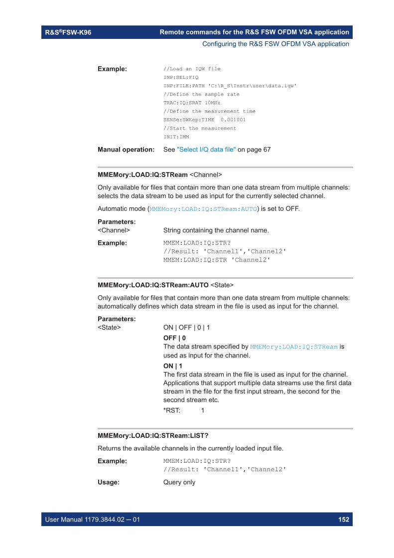
Remote commands for the R&S FSW OFDM VSA applicationR&S®FSW-K96
152User Manual 1179.3844.02 ─ 01
Example: //Load an IQW fileINP:SEL:FIQINP:FILE:PATH 'C:\R_S\Instr\user\data.iqw'//Define the sample rateTRAC:IQ:SRAT 10MHz//Define the measurement timeSENSe:SWEep:TIME 0.001001//Start the measurementINIT:IMM
Manual operation: See "Select I/Q data file" on page 67
MMEMory:LOAD:IQ:STReam <Channel>
Only available for files that contain more than one data stream from multiple channels:selects the data stream to be used as input for the currently selected channel.
Automatic mode (MMEMory:LOAD:IQ:STReam:AUTO) is set to OFF.
Parameters:<Channel> String containing the channel name.
Example: MMEM:LOAD:IQ:STR?//Result: 'Channel1','Channel2'MMEM:LOAD:IQ:STR 'Channel2'
MMEMory:LOAD:IQ:STReam:AUTO <State>
Only available for files that contain more than one data stream from multiple channels:automatically defines which data stream in the file is used as input for the channel.
Parameters:<State> ON | OFF | 0 | 1
OFF | 0The data stream specified by MMEMory:LOAD:IQ:STReam isused as input for the channel.ON | 1The first data stream in the file is used as input for the channel.Applications that support multiple data streams use the first datastream in the file for the first input stream, the second for thesecond stream etc.*RST: 1
MMEMory:LOAD:IQ:STReam:LIST?
Returns the available channels in the currently loaded input file.
Example: MMEM:LOAD:IQ:STR?//Result: 'Channel1','Channel2'
Usage: Query only
Configuring the R&S FSW OFDM VSA application
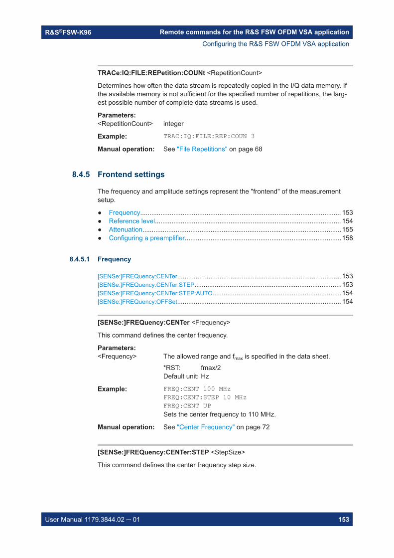
Remote commands for the R&S FSW OFDM VSA applicationR&S®FSW-K96
153User Manual 1179.3844.02 ─ 01
TRACe:IQ:FILE:REPetition:COUNt <RepetitionCount>
Determines how often the data stream is repeatedly copied in the I/Q data memory. Ifthe available memory is not sufficient for the specified number of repetitions, the larg-est possible number of complete data streams is used.
Parameters:<RepetitionCount> integer
Example: TRAC:IQ:FILE:REP:COUN 3Manual operation: See "File Repetitions" on page 68
8.4.5 Frontend settings
The frequency and amplitude settings represent the "frontend" of the measurementsetup.
● Frequency............................................................................................................. 153● Reference level..................................................................................................... 154● Attenuation............................................................................................................155● Configuring a preamplifier.....................................................................................158
8.4.5.1 Frequency
[SENSe:]FREQuency:CENTer......................................................................................... 153[SENSe:]FREQuency:CENTer:STEP................................................................................153[SENSe:]FREQuency:CENTer:STEP:AUTO......................................................................154[SENSe:]FREQuency:OFFSet......................................................................................... 154
[SENSe:]FREQuency:CENTer <Frequency>
This command defines the center frequency.
Parameters:<Frequency> The allowed range and fmax is specified in the data sheet.
*RST: fmax/2Default unit: Hz
Example: FREQ:CENT 100 MHzFREQ:CENT:STEP 10 MHzFREQ:CENT UPSets the center frequency to 110 MHz.
Manual operation: See "Center Frequency" on page 72
[SENSe:]FREQuency:CENTer:STEP <StepSize>
This command defines the center frequency step size.
Configuring the R&S FSW OFDM VSA application
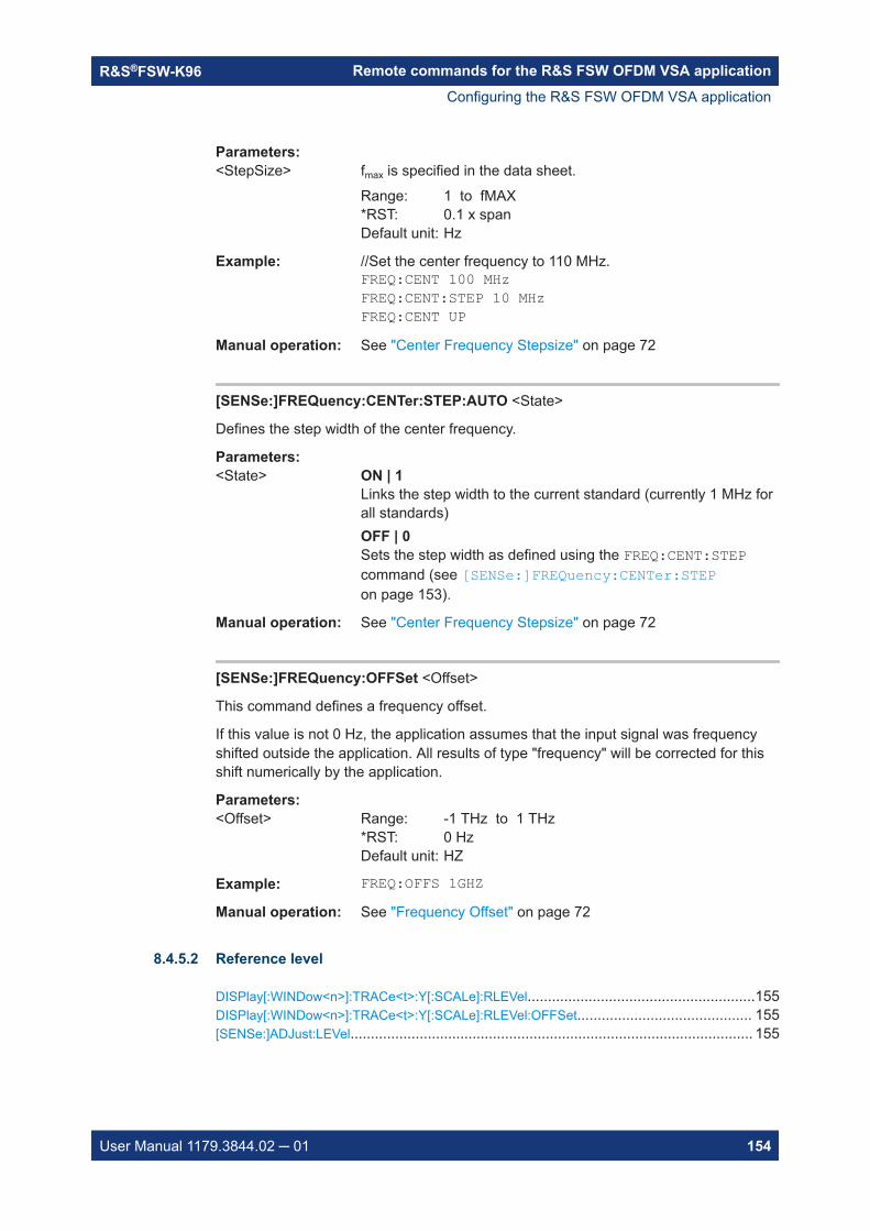
Remote commands for the R&S FSW OFDM VSA applicationR&S®FSW-K96
154User Manual 1179.3844.02 ─ 01
Parameters:<StepSize> fmax is specified in the data sheet.
Range: 1 to fMAX*RST: 0.1 x spanDefault unit: Hz
Example: //Set the center frequency to 110 MHz.FREQ:CENT 100 MHzFREQ:CENT:STEP 10 MHzFREQ:CENT UP
Manual operation: See "Center Frequency Stepsize" on page 72
[SENSe:]FREQuency:CENTer:STEP:AUTO <State>
Defines the step width of the center frequency.
Parameters:<State> ON | 1
Links the step width to the current standard (currently 1 MHz forall standards)OFF | 0Sets the step width as defined using the FREQ:CENT:STEPcommand (see [SENSe:]FREQuency:CENTer:STEPon page 153).
Manual operation: See "Center Frequency Stepsize" on page 72
[SENSe:]FREQuency:OFFSet <Offset>
This command defines a frequency offset.
If this value is not 0 Hz, the application assumes that the input signal was frequencyshifted outside the application. All results of type "frequency" will be corrected for thisshift numerically by the application.
Parameters:<Offset> Range: -1 THz to 1 THz
*RST: 0 HzDefault unit: HZ
Example: FREQ:OFFS 1GHZManual operation: See "Frequency Offset" on page 72
8.4.5.2 Reference level
DISPlay[:WINDow<n>]:TRACe<t>:Y[:SCALe]:RLEVel........................................................155DISPlay[:WINDow<n>]:TRACe<t>:Y[:SCALe]:RLEVel:OFFSet........................................... 155[SENSe:]ADJust:LEVel................................................................................................... 155
Configuring the R&S FSW OFDM VSA application

Remote commands for the R&S FSW OFDM VSA applicationR&S®FSW-K96
155User Manual 1179.3844.02 ─ 01
DISPlay[:WINDow<n>]:TRACe<t>:Y[:SCALe]:RLEVel <ReferenceLevel>
This command defines the reference level (for all traces in all windows).
Suffix: <n>
.irrelevant
<t> irrelevant
Example: DISP:TRAC:Y:RLEV -60dBmManual operation: See "Reference Level" on page 74
DISPlay[:WINDow<n>]:TRACe<t>:Y[:SCALe]:RLEVel:OFFSet <Offset>
This command defines a reference level offset (for all traces in all windows).
Suffix: <n>
.irrelevant
<t> irrelevant
Parameters:<Offset> Range: -200 dB to 200 dB
*RST: 0dBDefault unit: DB
Example: DISP:TRAC:Y:RLEV:OFFS -10dBManual operation: See "Shifting the Display (Offset)" on page 74
[SENSe:]ADJust:LEVel
This command initiates a single (internal) measurement that evaluates and sets theideal reference level for the current input data and measurement settings. This ensuresthat the settings of the RF attenuation and the reference level are optimally adjusted tothe signal level without overloading the R&S FSW or limiting the dynamic range by anS/N ratio that is too small.
Example: ADJ:LEVManual operation: See "Setting the Reference Level Automatically (Auto Level)"
on page 74
8.4.5.3 Attenuation
INPut<ip>:ATTenuation...................................................................................................156INPut<ip>:ATTenuation:AUTO......................................................................................... 156INPut<ip>:ATTenuation:AUTO:MODE...............................................................................156INPut<ip>:EATT.............................................................................................................157INPut<ip>:EATT:AUTO................................................................................................... 157INPut<ip>:EATT:STATe................................................................................................... 158
Configuring the R&S FSW OFDM VSA application

Remote commands for the R&S FSW OFDM VSA applicationR&S®FSW-K96
156User Manual 1179.3844.02 ─ 01
INPut<ip>:ATTenuation <Attenuation>
This command defines the total attenuation for RF input.
If you set the attenuation manually, it is no longer coupled to the reference level, butthe reference level is coupled to the attenuation. Thus, if the current reference level isnot compatible with an attenuation that has been set manually, the command alsoadjusts the reference level.
Suffix: <ip>
.1 | 2irrelevant
Parameters:<Attenuation> Range: see data sheet
Increment: 5 dB (with optional electr. attenuator: 1 dB)*RST: 10 dB (AUTO is set to ON)Default unit: DB
Example: INP:ATT 30dBDefines a 30 dB attenuation and decouples the attenuation fromthe reference level.
Manual operation: See "Attenuation Mode / Value" on page 76
INPut<ip>:ATTenuation:AUTO <State>
This command couples or decouples the attenuation to the reference level. Thus, whenthe reference level is changed, the R&S FSW determines the signal level for optimalinternal data processing and sets the required attenuation accordingly.
Suffix: <ip>
.1 | 2irrelevant
Parameters:<State> ON | OFF | 0 | 1
*RST: 1
Example: INP:ATT:AUTO ONCouples the attenuation to the reference level.
Manual operation: See "Attenuation Mode / Value" on page 76
INPut<ip>:ATTenuation:AUTO:MODE <OptMode>
Selects the priority for signal processing after the RF attenuation has been applied.
Suffix: <ip>
.1 | 2irrelevant
Parameters:<OptMode> LNOise | LDIStortion
Configuring the R&S FSW OFDM VSA application

Remote commands for the R&S FSW OFDM VSA applicationR&S®FSW-K96
157User Manual 1179.3844.02 ─ 01
LNOiseOptimized for high sensitivity and low noise levelsLDIStortionOptimized for low distortion by avoiding intermodulation*RST: LDIStortion (WLAN application: LNOise)
Example: INP:ATT:AUTO:MODE LNOManual operation: See "Optimization" on page 76
INPut<ip>:EATT <Attenuation>
This command defines an electronic attenuation manually. Automatic mode must beswitched off (INP:EATT:AUTO OFF, see INPut<ip>:EATT:AUTO on page 157).
If the current reference level is not compatible with an attenuation that has been setmanually, the command also adjusts the reference level.
Suffix: <ip>
.1 | 2irrelevant
Parameters:<Attenuation> attenuation in dB
Range: see data sheetIncrement: 1 dB*RST: 0 dB (OFF)Default unit: DB
Example: INP:EATT:AUTO OFFINP:EATT 10 dB
Manual operation: See "Using Electronic Attenuation" on page 77
INPut<ip>:EATT:AUTO <State>
This command turns automatic selection of the electronic attenuation on and off.
If on, electronic attenuation reduces the mechanical attenuation whenever possible.
Suffix: <ip>
.1 | 2irrelevant
Parameters:<State> ON | OFF | 0 | 1
OFF | 0Switches the function offON | 1Switches the function on*RST: 1
Example: INP:EATT:AUTO OFF
Configuring the R&S FSW OFDM VSA application

Remote commands for the R&S FSW OFDM VSA applicationR&S®FSW-K96
158User Manual 1179.3844.02 ─ 01
Manual operation: See "Using Electronic Attenuation" on page 77
INPut<ip>:EATT:STATe <State>
This command turns the electronic attenuator on and off.
Suffix: <ip>
.1 | 2irrelevant
Parameters:<State> ON | OFF | 0 | 1
OFF | 0Switches the function offON | 1Switches the function on*RST: 0
Example: INP:EATT:STAT ONSwitches the electronic attenuator into the signal path.
Manual operation: See "Using Electronic Attenuation" on page 77
8.4.5.4 Configuring a preamplifier
INPut<ip>:GAIN:STATe...................................................................................................158INPut<ip>:GAIN[:VALue].................................................................................................159
INPut<ip>:GAIN:STATe <State>
This command turns the internal preamplifier on and off. It requires the optional pream-plifier hardware.
Note that if an optional external preamplifier is activated, the internal preamplifier isautomatically disabled, and vice versa.
If option R&S FSW-B22 is installed, the preamplifier is only active below 7 GHz.
If option R&S FSW-B24 is installed, the preamplifier is active for all frequencies.
Suffix: <ip>
.1 | 2irrelevant
Parameters:<State> ON | OFF | 0 | 1
OFF | 0Switches the function offON | 1Switches the function on*RST: 0
Configuring the R&S FSW OFDM VSA application
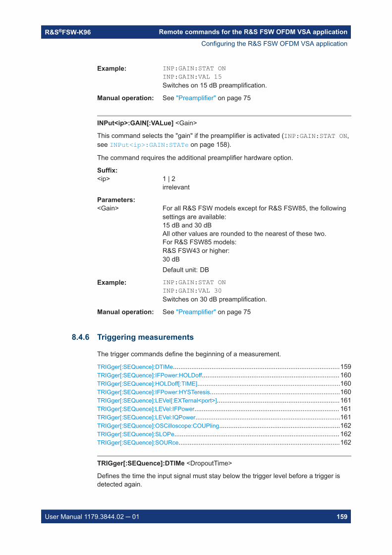
Remote commands for the R&S FSW OFDM VSA applicationR&S®FSW-K96
159User Manual 1179.3844.02 ─ 01
Example: INP:GAIN:STAT ONINP:GAIN:VAL 15Switches on 15 dB preamplification.
Manual operation: See "Preamplifier" on page 75
INPut<ip>:GAIN[:VALue] <Gain>
This command selects the "gain" if the preamplifier is activated (INP:GAIN:STAT ON,see INPut<ip>:GAIN:STATe on page 158).
The command requires the additional preamplifier hardware option.
Suffix: <ip>
.1 | 2irrelevant
Parameters:<Gain> For all R&S FSW models except for R&S FSW85, the following
settings are available:15 dB and 30 dBAll other values are rounded to the nearest of these two.For R&S FSW85 models:R&S FSW43 or higher:30 dBDefault unit: DB
Example: INP:GAIN:STAT ONINP:GAIN:VAL 30Switches on 30 dB preamplification.
Manual operation: See "Preamplifier" on page 75
8.4.6 Triggering measurements
The trigger commands define the beginning of a measurement.
TRIGger[:SEQuence]:DTIMe...........................................................................................159TRIGger[:SEQuence]:IFPower:HOLDoff........................................................................... 160TRIGger[:SEQuence]:HOLDoff[:TIME]..............................................................................160TRIGger[:SEQuence]:IFPower:HYSTeresis.......................................................................160TRIGger[:SEQuence]:LEVel[:EXTernal<port>]...................................................................161TRIGger[:SEQuence]:LEVel:IFPower............................................................................... 161TRIGger[:SEQuence]:LEVel:IQPower...............................................................................161TRIGger[:SEQuence]:OSCilloscope:COUPling..................................................................162TRIGger[:SEQuence]:SLOPe.......................................................................................... 162TRIGger[:SEQuence]:SOURce........................................................................................162
TRIGger[:SEQuence]:DTIMe <DropoutTime>
Defines the time the input signal must stay below the trigger level before a trigger isdetected again.
Configuring the R&S FSW OFDM VSA application

Remote commands for the R&S FSW OFDM VSA applicationR&S®FSW-K96
160User Manual 1179.3844.02 ─ 01
Parameters:<DropoutTime> Dropout time of the trigger.
Range: 0 s to 10.0 s*RST: 0 sDefault unit: S
Manual operation: See "Drop-Out Time" on page 81
TRIGger[:SEQuence]:IFPower:HOLDoff <Period>
This command defines the holding time before the next trigger event.
Note that this command can be used for any trigger source, not just IF Power(despite the legacy keyword).
Parameters:<Period> Range: 0 s to 10 s
*RST: 0 sDefault unit: S
Example: TRIG:SOUR EXTSets an external trigger source.TRIG:IFP:HOLD 200 nsSets the holding time to 200 ns.
Manual operation: See "Trigger Holdoff" on page 82
TRIGger[:SEQuence]:HOLDoff[:TIME] <Offset>
Defines the time offset between the trigger event and the start of the measurement.
Parameters:<Offset> *RST: 0 s
Default unit: S
Example: TRIG:HOLD 500usManual operation: See "Trigger Offset" on page 81
TRIGger[:SEQuence]:IFPower:HYSTeresis <Hysteresis>
This command defines the trigger hysteresis, which is only available for "IF Power" trig-ger sources.
Parameters:<Hysteresis> Range: 3 dB to 50 dB
*RST: 3 dBDefault unit: DB
Example: TRIG:SOUR IFPSets the IF power trigger source.TRIG:IFP:HYST 10DBSets the hysteresis limit value.
Configuring the R&S FSW OFDM VSA application
Remote commands for the R&S FSW OFDM VSA applicationR&S®FSW-K96
161User Manual 1179.3844.02 ─ 01
Manual operation: See "Hysteresis" on page 81
TRIGger[:SEQuence]:LEVel[:EXTernal<port>] <TriggerLevel>
This command defines the level the external signal must exceed to cause a triggerevent.
Suffix: <port>
.Selects the trigger port.1 = trigger port 1 (TRIGGER INPUT connector on front panel)2 = trigger port 2 (TRIGGER INPUT/OUTPUT connector on frontpanel)(Not available for R&S FSW85 models with two RF input con-nectors.)3 = trigger port 3 (TRIGGER3 INPUT/OUTPUT connector onrear panel)
Parameters:<TriggerLevel> Range: 0.5 V to 3.5 V
*RST: 1.4 VDefault unit: V
Example: TRIG:LEV 2VManual operation: See "Trigger Level" on page 81
TRIGger[:SEQuence]:LEVel:IFPower <TriggerLevel>
This command defines the power level at the third intermediate frequency that must beexceeded to cause a trigger event.
Note that any RF attenuation or preamplification is considered when the trigger level isanalyzed. If defined, a reference level offset is also considered.
Parameters:<TriggerLevel> For details on available trigger levels and trigger bandwidths see
the data sheet.*RST: -20 dBmDefault unit: DBM
Example: TRIG:LEV:IFP -30DBM
TRIGger[:SEQuence]:LEVel:IQPower <TriggerLevel>
This command defines the magnitude the I/Q data must exceed to cause a triggerevent.
Note that any RF attenuation or preamplification is considered when the trigger level isanalyzed. If defined, a reference level offset is also considered.
Configuring the R&S FSW OFDM VSA application

Remote commands for the R&S FSW OFDM VSA applicationR&S®FSW-K96
162User Manual 1179.3844.02 ─ 01
Parameters:<TriggerLevel> Range: -130 dBm to 30 dBm
*RST: -20 dBmDefault unit: DBM
Example: TRIG:LEV:IQP -30DBM
TRIGger[:SEQuence]:OSCilloscope:COUPling <CoupType>
Configures the coupling of the external trigger to the oscilloscope.
Parameters:<CoupType> Coupling type
DCDirect connection with 50 Ω termination, passes both DC andAC components of the trigger signal.CDLimitDirect connection with 1 MΩ termination, passes both DC andAC components of the trigger signal.ACConnection through capacitor, removes unwanted DC and verylow-frequency components.*RST: DC
Manual operation: See "Coupling" on page 82
TRIGger[:SEQuence]:SLOPe <Type>
Parameters:<Type> POSitive | NEGative
POSitiveTriggers when the signal rises to the trigger level (rising edge).NEGativeTriggers when the signal drops to the trigger level (falling edge).*RST: POSitive
Example: TRIG:SLOP NEGManual operation: See "Slope" on page 82
TRIGger[:SEQuence]:SOURce <Source>
This command selects the trigger source.
Note on external triggers:
Configuring the R&S FSW OFDM VSA application

Remote commands for the R&S FSW OFDM VSA applicationR&S®FSW-K96
163User Manual 1179.3844.02 ─ 01
If a measurement is configured to wait for an external trigger signal in a remote controlprogram, remote control is blocked until the trigger is received and the program cancontinue. Make sure this situation is avoided in your remote control programs.
Parameters:<Source> IMMediate
Free RunEXTernalTrigger signal from the "Trigger Input" connector.If power splitter mode is active, this parameter activates the"EXT TRIGGER INPUT" connector on the oscilloscope. Thenthe R&S FSW triggers when the signal fed into the "EXT TRIG-GER INPUT" connector on the oscilloscope meets or exceedsthe specified trigger level.EXT2Trigger signal from the "Trigger Input/Output" connector.For R&S FSW85 models, Trigger 2 is not available due to thesecond RF input connector on the front panel. The trigger signalis taken from the "Trigger Input/Output" connector on the rearpanel.Note: Connector must be configured for "Input".EXT3Trigger signal from the "TRIGGER 3 INPUT/ OUTPUT" connec-tor.Note: Connector must be configured for "Input".*RST: IMMediate
Example: TRIG:SOUR EXTSelects the external trigger input as source of the trigger signal
Manual operation: See "Trigger Source" on page 78See "Free Run" on page 78See "External Trigger 1/2/3" on page 78See "External Channel 3" on page 79See "IF Power" on page 79See "Baseband Power" on page 80See "I/Q Power" on page 80See "RF Power" on page 80See "Digital I/Q" on page 80
8.4.7 Configuring data acquisition
INPut<ip>:FILTer:CHANnel:HPASs:FDBBw?.....................................................................164INPut<ip>:FILTer:CHANnel:HPASs:SDBBw...................................................................... 164INPut<ip>:FILTer:CHANnel:HPASs[:STATe].......................................................................164INPut<ip>:FILTer:CHANnel[:LPASs]:FDBBw..................................................................... 165INPut<ip>:FILTer:CHANnel[:LPASs]:SDBBw..................................................................... 165INPut<ip>:FILTer:CHANnel[:LPASs][:STATe]..................................................................... 165[SENSe:]SWAPiq...........................................................................................................166
Configuring the R&S FSW OFDM VSA application
Remote commands for the R&S FSW OFDM VSA applicationR&S®FSW-K96
164User Manual 1179.3844.02 ─ 01
[SENSe:]SWEep:COUNt.................................................................................................166[SENSe:]SWEep:LENGth................................................................................................166[SENSe:]SWEep:TIME................................................................................................... 167TRACe:IQ:BWIDth......................................................................................................... 167TRACe:IQ:SRATe...........................................................................................................167TRACe:IQ:WBANd[:STATe].............................................................................................167TRACe:IQ:WBANd:MBWidth...........................................................................................168
INPut<ip>:FILTer:CHANnel:HPASs:FDBBw?
Suffix: <ip>
.1..n
Return values: <Frequency> Default unit: HZ
Usage: Query only
Manual operation: See "50-dB Bandwidth" on page 86
INPut<ip>:FILTer:CHANnel:HPASs:SDBBw <Frequency>
Configures the bandwidth of the high pass filter at which an attenuation of 6 dB isreached. The filter bandwidth cannot be higher than the current sample rate. If neces-sary, the filter bandwidth is adapted to the current sample rate.
Suffix: <ip>
.1..n
Parameters:<Frequency> Default unit: HZ
Example: INPU:FILT:CHAN:HPAS:SDBB 30 MHZManual operation: See "6-dB Bandwidth" on page 85
INPut<ip>:FILTer:CHANnel:HPASs[:STATe] <State>
Activates an additional internal highpass filter.
Suffix: <ip>
.1..n
Parameters:<State> ON | OFF | 0 | 1
OFF | 0Switches the filter off.ON | 1Switches the filter on*RST: 0
Example: INP:FILT:CHAN:HPAS ONManual operation: See "Highpass Filter State" on page 85
Configuring the R&S FSW OFDM VSA application

Remote commands for the R&S FSW OFDM VSA applicationR&S®FSW-K96
165User Manual 1179.3844.02 ─ 01
INPut<ip>:FILTer:CHANnel[:LPASs]:FDBBw <Frequency>
Configures the 50-dB frequency of the channel filter. The 50-dB frequency is the dis-tance from the center of the filter to the point at which the filter reaches an attenuationof 50 dB. This frequency must always be larger than the 6-dB passband (seeINPut<ip>:FILTer:CHANnel[:LPASs]:SDBBw on page 165).
Suffix: <ip>
.1 | 2irrelevant
Parameters:<Frequency> Default unit: HZ
Example: INP:FILT:CHAN:FDBB 40MHZManual operation: See "50-dB Bandwidth" on page 85
INPut<ip>:FILTer:CHANnel[:LPASs]:SDBBw <Frequency>
Configures the 6-dB bandwidth of the channel filter. The filter bandwidth cannot behigher than the current 50-dB frequency (see INPut<ip>:FILTer:CHANnel[:LPASs]:FDBBw on page 165).
Suffix: <ip>
.1 | 2irrelevant
Parameters:<Frequency> Default unit: HZ
Example: INP:FILT:CHAN:SDBB 30MHZManual operation: See "6-dB Bandwidth" on page 85
INPut<ip>:FILTer:CHANnel[:LPASs][:STATe] <State>
This command turns an adjustable (lowpass) channel filter in the signal path on andoff.
You can define its characteristics with● INPut<ip>:FILTer:CHANnel[:LPASs]:SDBBw on page 165● INPut<ip>:FILTer:CHANnel[:LPASs]:FDBBw on page 165
Suffix: <ip>
.1 | 2irrelevant
Parameters:<State> ON | OFF
*RST: OFF
Example: INP:FILT:CHAN ONTurns on the adjustable channel filter.
Configuring the R&S FSW OFDM VSA application

Remote commands for the R&S FSW OFDM VSA applicationR&S®FSW-K96
166User Manual 1179.3844.02 ─ 01
Manual operation: See "Filter State" on page 84
[SENSe:]SWAPiq <State>
This command defines whether or not the recorded I/Q pairs should be swapped (I<->Q) before being processed. Swapping I and Q inverts the sideband.
This is useful if the DUT interchanged the I and Q parts of the signal; then theR&S FSW can do the same to compensate for it.
Parameters:<State> ON | 1
I and Q signals are interchangedInverted sideband, Q+j*IOFF | 0I and Q signals are not interchangedNormal sideband, I+j*Q*RST: 0
Manual operation: See "Swap I/Q" on page 84
[SENSe:]SWEep:COUNt <SweepCount>
This command defines the number of measurements that the application uses to aver-age traces.
In case of continuous measurement mode, the application calculates the moving aver-age over the average count.
In case of single measurement mode, the application stops the measurement and cal-culates the average after the average count has been reached.
Suffix: <n>
.Window
Example: SWE:COUN 64Sets the number of measurements to 64.INIT:CONT OFFSwitches to single measurement mode.INIT;*WAIStarts a measurement and waits for its end.
[SENSe:]SWEep:LENGth <Length>
Defines the number of samples to be captured during each measurement.
Parameters:<Length> integer
Range: 1 to 8 000 000
Example: SENSe:SWEep:LENGth 1001Manual operation: See "Capture Length" on page 83
Configuring the R&S FSW OFDM VSA application

Remote commands for the R&S FSW OFDM VSA applicationR&S®FSW-K96
167User Manual 1179.3844.02 ─ 01
[SENSe:]SWEep:TIME <Time>
This command defines the measurement time. It automatically decouples the time fromany other settings.
Parameters:<Time> refer to data sheet
*RST: depends on current settings (determined automati-cally)
Default unit: S
Manual operation: See "Capture Time" on page 83
TRACe:IQ:BWIDth <Bandwidth>
This command queries the bandwidth in Hz of the resampling filter ("Usable I/Q Band-width").
Parameters:<Bandwidth> Usable I/Q bandwidth
Default unit: Hz
Example: TRAC1:IQ:BWID?
TRACe:IQ:SRATe <SampleRate>
This command sets the final user sample rate for the acquired I/Q data. Thus, the usersample rate can be modified without affecting the actual data capturing settings on theR&S FSW.
Parameters:<SampleRate> The valid sample rates are described in Chapter 3.5, "Sample
rate and maximum usable I/Q bandwidth for RF input",on page 39.*RST: 32 MHzDefault unit: HZ
Manual operation: See "Sample Rate" on page 83
TRACe:IQ:WBANd[:STATe] <State>
This command determines whether the wideband provided by bandwidth extensionoptions is used or not (if installed).
Parameters:<State> ON | OFF | 0 | 1
OFF | 0Switches the function offON | 1Switches the function on
Configuring the R&S FSW OFDM VSA application

Remote commands for the R&S FSW OFDM VSA applicationR&S®FSW-K96
168User Manual 1179.3844.02 ─ 01
Manual operation: See "Maximum Bandwidth" on page 84
TRACe:IQ:WBANd:MBWidth <Limit>
Defines the maximum analysis bandwidth. Any value can be specified; the next higherfixed bandwidth is used.
Defining a value other than "MAX" is useful if you want to specify the sample ratedirectly and at the same time, ensure a minimum bandwidth is available.
Parameters:<Limit> 80 MHz
Restricts the analysis bandwidth to a maximum of 80 MHz.The bandwidth extension options greater than 160 MHz are dis-abled.TRACe:IQ:WBANd[:STATe] is set to OFF.160 MHzRestricts the analysis bandwidth to a maximum of 160 MHz. Thebandwidth extension option R&S FSW-B320 is deactivated.(Not available or required if other bandwidth extension optionslarger than 320 MHz are installed.)TRACe:IQ:WBANd[:STATe] is set to ON.1200 MHz | 500 MHz | 320 MHz | MAXAll installed bandwidth extension options are activated. The cur-rently available maximum bandwidth is allowed.TRACe:IQ:WBANd[:STATe] is set to ON.*RST: maximum availableDefault unit: Hz
Example: TRAC:IQ:WBAN:MBW 82 MHZTRAC:IQ:WBAN:MBW?Result if R&S FSW-B160/-B320 is active:160000000
Example: TRAC:IQ:WBAN:MBW 82 MHZTRAC:IQ:WBAN:MBW?Result if R&S FSW-B512 is active:512000000
Manual operation: See "Maximum Bandwidth" on page 84
8.4.8 Enabling a burst search
[SENSe:]DEMod:FORMat:BURSt <State>
This command turns a search for bursted OFDM signals on and off.
Parameters:<State> ON | OFF
*RST: ON
Configuring the R&S FSW OFDM VSA application

Remote commands for the R&S FSW OFDM VSA applicationR&S®FSW-K96
169User Manual 1179.3844.02 ─ 01
Example: DEM:FORM:BURS ONTurns on the burst search.
Manual operation: See "Burst Search State" on page 87
8.4.9 Defining the result range
The result range determines which part of the capture buffer or burst is displayed.
[SENSe:]DEMod:FORMat:MAXFrames............................................................................ 169[SENSe:]DEMod:FORMat:NOFSymbols...........................................................................169
[SENSe:]DEMod:FORMat:MAXFrames <NFrames>
This command defines the maximum number of frames to be demodulated.
Parameters:<NFrames> Numeric value.
*RST: 1
Example: DEM:FORM:MAXF 10Defines a maximum of 10 frames to be demodulated.
Manual operation: See "Statistic Config / Max No of Frames to Analyze"on page 87
[SENSe:]DEMod:FORMat:NOFSymbols <NSymbols>
This command defines the number of symbols in a frame.
Note that frames with fewer symbols are not analyzed.
Parameters:<NSymbols> Range: 4 to 2000
*RST: 10
Example: DEM:FORM:NOFS 44Defines 44 symbols per frame.
Manual operation: See "Result Length" on page 88
8.4.10 Synchronization, tracking and demodulation
[SENSe:]COMPensate:CHANnel..................................................................................... 170[SENSe:]DEMod:CDD.................................................................................................... 170[SENSe:]DEMod:COFFset.............................................................................................. 170[SENSe:]DEMod:FFTShift...............................................................................................170[SENSe:]DEMod:FSYNc.................................................................................................171[SENSe:]DEMod:MDETect.............................................................................................. 171[SENSe:]DEMod:THReshold:TIME.................................................................................. 171[SENSe:]DEMod:THReshold:FRAMe............................................................................... 172[SENSe:]DEMod:TSYNc.................................................................................................172
Configuring the R&S FSW OFDM VSA application

Remote commands for the R&S FSW OFDM VSA applicationR&S®FSW-K96
170User Manual 1179.3844.02 ─ 01
SENSe:TRACking:LEVel.................................................................................................173SENSe:TRACking:PHASe.............................................................................................. 173SENSe:TRACking:TIME................................................................................................. 173
[SENSe:]COMPensate:CHANnel <State>
This command turns compensation for the estimated channel transfer function on andoff.
Parameters:<State> ON | OFF
*RST: ON
Example: COMP:CHAN ONTurns on channel compensation.
Manual operation: See " Channel Compensation" on page 91
[SENSe:]DEMod:CDD <CyclicShift>
This command defines the cyclic delay.
Parameters:<CyclicShift> Cyclic delay in samples.
Range: –<CP length> to +<CP length>*RST: 0
Example: DEM:CDD 5Defines a cyclic delay of 5 samples.
Manual operation: See "Cyclic Delay" on page 92
[SENSe:]DEMod:COFFset <MaxCarrierOffset>
This command defines the maximum allowed carrier offset for frame synchronization.
Parameters:<MaxCarrierOffset> Frequency offset in terms of (sub)carriers.
*RST: 0
Example: SENS:DEM:COFF 2Defines a frequency offset of two subcarriers.
Manual operation: See " Maximum Carrier Offset" on page 92
[SENSe:]DEMod:FFTShift <FFTShift>
This command defines an offset for the FFT start sample in the guard interval.
Parameters:<FFTShift> Numeric value that defines the FFT shift.
The value is normalized to the length of the guard interval.*RST: 0.5
Configuring the R&S FSW OFDM VSA application

Remote commands for the R&S FSW OFDM VSA applicationR&S®FSW-K96
171User Manual 1179.3844.02 ─ 01
Example: DEM:FFTS 0.6Defines an FFT shift of 0.6.
Manual operation: See " FFT Shift relative to Cyclic Prefix Length" on page 92
[SENSe:]DEMod:FSYNc <Mode>
This command selects the parameter estimation mode.
Parameters:<Mode> DATA
Demodulator uses pilot and data cells for synchronization.PILDemodulator uses only pilot cells for synchronization.NONEReturn value only.The software returns NONE if no configuration file has been loa-ded.*RST: PIL
Example: DEM:FSYN PILSelects synchronization based on the pilot cells.
Manual operation: See " Parameter Estimation" on page 89
[SENSe:]DEMod:MDETect <Mode>
This command selects the auto demodulation mode.
Parameters:<Mode> CARR
Assumes one constellation for all data cells in the carriers.CFGEvaluates the modulation matrix within the configuration file.SYMBAssigns the data cells of each symbol to one constellation.*RST: CFG
Example: DEM:MDET CFGSelects evaluation of the modulation matrix in the configurationfile.
Manual operation: See " Modulation Detection" on page 90
[SENSe:]DEMod:THReshold:TIME <Reliability>
Sets and queries the reliability threshold for time synchronisation.
Values between 0 and 1 are allowed, where:● 0: low threshold, a very poor reliability is sufficient to synchronize successfully
(always fulfilled)
Configuring the R&S FSW OFDM VSA application
Remote commands for the R&S FSW OFDM VSA applicationR&S®FSW-K96
172User Manual 1179.3844.02 ─ 01
● 1: high threshold, time synchronization must be absolutely reliable to be successful(only possible for ideal signal).
The default value is 0.5, that means: for a reliability of 50 %, time synchronization issuccessful.
Parameters:<Reliability> Range: 0 to 1
*RST: 0.5
Example: SENS:DEM:THR:TIME 0.5Manual operation: See "Minimum Time Sync Metric" on page 90
[SENSe:]DEMod:THReshold:FRAMe <Reliability>
Sets and queries the reliability threshold for frame synchronisation.
Values between 0 and 1 are allowed, where:● 0: low threshold, a very poor correlation is sufficient to synchronize successfully
(always fulfilled)● 1: high threshold, correlation must be very precise for frame synchronization to be
successful (only possible for ideal signal).
The default value is 0.5, that means: for a correlation of 50 %, frame synchronization issuccessful.
Parameters:<Reliability> Range: 0 to 1
*RST: 0.5
Example: SENS:DEM:THR:FRAM 0.5Manual operation: See "Minimum Frame Sync Metric" on page 91
[SENSe:]DEMod:TSYNc <Mode>
This command selects the time synchronization mode.
Parameters:<Mode> CP
Performs time synchronization by correlating the cyclic prefix.PREamblePerforms time synchronization by correlating the recurring pre-amble structure.*RST: CP
Example: DEM:TSYN CPSelects time synchronization based on the cyclic prefix.
Manual operation: See " Time Synchronization" on page 89
Configuring the R&S FSW OFDM VSA application
Remote commands for the R&S FSW OFDM VSA applicationR&S®FSW-K96
173User Manual 1179.3844.02 ─ 01
SENSe:TRACking:LEVel <State>
This command turns tracking of the power level on and off.
Note
The syntax element [SENSe] is not optional for this command.
Parameters:<State> ON | OFF
*RST: OFF
Example: SENS:TRAC:LEV ONTurns on power level tracking.
Manual operation: See " Level Tracking" on page 91
SENSe:TRACking:PHASe <State>
This command turns phase tracking on and off.
Note
The syntax element [SENSe] is not optional for this command.
Parameters:<State> ON | OFF
*RST: ON
Example: SENS:TRAC:PHAS ONTurns on phase tracking.
Manual operation: See " Phase Tracking" on page 91
SENSe:TRACking:TIME <State>
This command turns tracking of the sample clock deviation on and off.
Note
The syntax element [SENSe] is not optional for this command.
Parameters:<State> ON | OFF
*RST: OFF
Example: SENS:TRAC:TIME ONTurns on tracking of sample clock deviations.
Manual operation: See " Timing Tracking" on page 91
8.4.11 Adjusting settings automatically
Some settings can be adjusted by the R&S FSW automatically according to the currentmeasurement settings.
Configuring the R&S FSW OFDM VSA application

Remote commands for the R&S FSW OFDM VSA applicationR&S®FSW-K96
174User Manual 1179.3844.02 ─ 01
Useful commands for adjusting settings automatically described elsewhere:● [SENSe:]ADJust:LEVel on page 155
Remote commands exclusive to adjusting settings automatically:
[SENSe:]ADJust:CONFigure:LEVel:DURation...................................................................174[SENSe:]ADJust:CONFigure:LEVel:DURation:MODE........................................................ 174[SENSe:]ADJust:CONFigure:HYSTeresis:LOWer.............................................................. 175[SENSe:]ADJust:CONFigure:HYSTeresis:UPPer...............................................................175[SENSe:]ADJust:CONFigure:TRIGger..............................................................................175
[SENSe:]ADJust:CONFigure:LEVel:DURation <Duration>
In order to determine the ideal reference level, the R&S FSW performs a measurementon the current input data. This command defines the length of the measurement if[SENSe:]ADJust:CONFigure:LEVel:DURation:MODE is set to MANual.
Parameters:<Duration> Numeric value in seconds
Range: 0.001 to 16000.0*RST: 0.001Default unit: s
Example: ADJ:CONF:DUR:MODE MANSelects manual definition of the measurement length.ADJ:CONF:LEV:DUR 5msLength of the measurement is 5 ms.
[SENSe:]ADJust:CONFigure:LEVel:DURation:MODE <Mode>
In order to determine the ideal reference level, the R&S FSW performs a measurementon the current input data. This command selects the way the R&S FSW determines thelength of the measurement .
Parameters:<Mode> AUTO
The R&S FSW determines the measurement length automati-cally according to the current input data.MANualThe R&S FSW uses the measurement length defined by[SENSe:]ADJust:CONFigure:LEVel:DURationon page 174.*RST: AUTO
Configuring the R&S FSW OFDM VSA application
Remote commands for the R&S FSW OFDM VSA applicationR&S®FSW-K96
175User Manual 1179.3844.02 ─ 01
[SENSe:]ADJust:CONFigure:HYSTeresis:LOWer <Threshold>
When the reference level is adjusted automatically using the [SENSe:]ADJust:LEVel on page 155 command, the internal attenuators and the preamplifier are alsoadjusted. In order to avoid frequent adaptation due to small changes in the input signal,you can define a hysteresis. This setting defines a lower threshold the signal must fallbelow (compared to the last measurement) before the reference level is adapted auto-matically.
Parameters:<Threshold> Range: 0 dB to 200 dB
*RST: +1 dBDefault unit: dB
Example: SENS:ADJ:CONF:HYST:LOW 2For an input signal level of currently 20 dBm, the reference levelwill only be adjusted when the signal level falls below 18 dBm.
[SENSe:]ADJust:CONFigure:HYSTeresis:UPPer <Threshold>
When the reference level is adjusted automatically using the [SENSe:]ADJust:LEVel on page 155 command, the internal attenuators and the preamplifier are alsoadjusted. In order to avoid frequent adaptation due to small changes in the input signal,you can define a hysteresis. This setting defines an upper threshold the signal mustexceed (compared to the last measurement) before the reference level is adaptedautomatically.
Parameters:<Threshold> Range: 0 dB to 200 dB
*RST: +1 dBDefault unit: dB
Example: SENS:ADJ:CONF:HYST:UPP 2Example: For an input signal level of currently 20 dBm, the reference level
will only be adjusted when the signal level rises above 22 dBm.
[SENSe:]ADJust:CONFigure:TRIGger <State>
Defines the behavior of the measurement when adjusting a setting automatically (usingSENS:ADJ:LEV ON, for example).
Parameters:<State> ON | OFF | 0 | 1
OFF | 0Switches the function offON | 1Switches the function on
Configuring the R&S FSW OFDM VSA application
Remote commands for the R&S FSW OFDM VSA applicationR&S®FSW-K96
176User Manual 1179.3844.02 ─ 01
8.4.12 Output settings
The following commands are required to query or provide output at the R&S FSW con-nectors.
DIAGnostic:SERVice:NSOurce <State>
This command turns the 28 V supply of the BNC connector labeled [noise sourcecontrol] on the R&S FSW on and off.
Parameters:<State> ON | OFF | 0 | 1
OFF | 0Switches the function offON | 1Switches the function on
Example: DIAG:SERV:NSO ONManual operation: See "Noise Source Control" on page 69
OUTPut<up>:IF:SBANd?
This command queries the sideband provided at the "IF OUT 2 GHz" connector com-pared to the sideband of the RF signal. The sideband depends on the current centerfrequency.
Suffix: <up>
.
Return values: <SideBand> NORMal
The sideband at the output is identical to the RF signal.INVertedThe sideband at the output is the inverted RF signal sideband.
Example: OUTP:IF IF2Activates output at the IF OUTPUT (2 GHZ) connector.OUTP:IF:SBAN?Queries the sideband provided at the connector.
Usage: Query only
OUTPut<up>:IF[:SOURce] <Source>
Defines the type of signal available at one of the output connectors of the R&S FSW.
Suffix: <up>
.
Configuring the R&S FSW OFDM VSA application

Remote commands for the R&S FSW OFDM VSA applicationR&S®FSW-K96
177User Manual 1179.3844.02 ─ 01
Parameters:<Source> IF
The measured IF value is available at the IF/VIDEO/DEMODoutput connector.*RST: IF
Example: OUTP:IF VIDSelects the video signal for the IF/VIDEO/DEMOD output con-nector.
Manual operation: See "Data Output" on page 69
8.4.13 Configuring the trigger output
The following commands are required to send the trigger signal to one of the variable"TRIGGER INPUT/OUTPUT" connectors on the R&S FSW.
OUTPut<up>:TRIGger<tp>:DIRection.............................................................................. 177OUTPut<up>:TRIGger<tp>:LEVel....................................................................................177OUTPut<up>:TRIGger<tp>:OTYPe..................................................................................178OUTPut<up>:TRIGger<tp>:PULSe:IMMediate.................................................................. 179OUTPut<up>:TRIGger<tp>:PULSe:LENGth......................................................................179
OUTPut<up>:TRIGger<tp>:DIRection <Direction>
This command selects the trigger direction for trigger ports that serve as an input aswell as an output.
Suffix: <up>
.irrelevant
<tp> Selects the used trigger port.2 = trigger port 2 (front)3 = trigger port 3 (rear panel)
Parameters:<Direction> INPut | OUTPut
INPutPort works as an input.OUTPutPort works as an output.*RST: INPut
Manual operation: See "Trigger 2/3" on page 70
OUTPut<up>:TRIGger<tp>:LEVel <Level>
This command defines the level of the (TTL compatible) signal generated at the triggeroutput.
Configuring the R&S FSW OFDM VSA application

Remote commands for the R&S FSW OFDM VSA applicationR&S®FSW-K96
178User Manual 1179.3844.02 ─ 01
This command works only if you have selected a user defined output withOUTPut<up>:TRIGger<tp>:OTYPe.
Suffix: <up>
.1..n
<tp> Selects the trigger port to which the output is sent.2 = trigger port 2 (front)(Not available for R&S FSW85 models with two RF input con-nectors.)3 = trigger port 3 (rear)
Parameters:<Level> HIGH
5 VLOW0 V*RST: LOW
Example: OUTP:TRIG2:LEV HIGHManual operation: See "Level" on page 71
OUTPut<up>:TRIGger<tp>:OTYPe <OutputType>
This command selects the type of signal generated at the trigger output.
Suffix: <up>
.1..n
<tp> Selects the trigger port to which the output is sent.2 = trigger port 2 (front)(Not available for R&S FSW85 models with two RF input con-nectors.)3 = trigger port 3 (rear)
Parameters:<OutputType> DEVice
Sends a trigger signal when the R&S FSW has triggered inter-nally.TARMedSends a trigger signal when the trigger is armed and ready foran external trigger event.UDEFinedSends a user defined trigger signal. For more information seeOUTPut<up>:TRIGger<tp>:LEVel.*RST: DEVice
Manual operation: See "Output Type" on page 70
Configuring the R&S FSW OFDM VSA application
Remote commands for the R&S FSW OFDM VSA applicationR&S®FSW-K96
179User Manual 1179.3844.02 ─ 01
OUTPut<up>:TRIGger<tp>:PULSe:IMMediate
This command generates a pulse at the trigger output.
Suffix: <up>
.Selects the trigger port to which the output is sent.2 = trigger port 2 (front)(Not available for R&S FSW85 models with two RF input con-nectors.)3 = trigger port 3 (rear)
<tp> 1..n
Manual operation: See "Send Trigger" on page 71
OUTPut<up>:TRIGger<tp>:PULSe:LENGth <Length>
This command defines the length of the pulse generated at the trigger output.
Suffix: <up>
.1..n
<tp> Selects the trigger port to which the output is sent.2 = trigger port 2 (front)(Not available for R&S FSW85 models with two RF input con-nectors.)3 = trigger port 3 (rear)
Parameters:<Length> Pulse length in seconds.
Default unit: S
Example: OUTP:TRIG2:PULS:LENG 0.02Manual operation: See "Pulse Length" on page 71
8.5 Performing a measurement
When the VSA application is activated, a continuous sweep is performed automatically.However, you can stop and start a new measurement any time.
Furthermore, you can perform a sequence of measurements using the Sequencer (see"Multiple Measurement Channels and Sequencer Function" on page 6).
ABORt.......................................................................................................................... 180INITiate<n>:CONMeas................................................................................................... 180INITiate<n>:CONTinuous................................................................................................181INITiate<n>[:IMMediate]..................................................................................................181INITiate:REFResh.......................................................................................................... 181INITiate:SEQuencer:ABORt............................................................................................ 182
Performing a measurement

Remote commands for the R&S FSW OFDM VSA applicationR&S®FSW-K96
180User Manual 1179.3844.02 ─ 01
INITiate:SEQuencer:IMMediate....................................................................................... 182INITiate:SEQuencer:MODE.............................................................................................182SYSTem:SEQuencer......................................................................................................183
ABORt
This command aborts the measurement in the current channel and resets the triggersystem.
To prevent overlapping execution of the subsequent command before the measure-ment has been aborted successfully, use the *OPC? or *WAI command after ABOR andbefore the next command.
For details on overlapping execution see Remote control via SCPI.
Note on blocked remote control programs:
If a sequential command cannot be completed, for example because a triggered sweepnever receives a trigger, the remote control program will never finish and the remotechannel to the R&S FSW is blocked for further commands. In this case, you must inter-rupt processing on the remote channel first in order to abort the measurement.
To do so, send a "Device Clear" command from the control instrument to the R&S FSWon a parallel channel to clear all currently active remote channels. Depending on theused interface and protocol, send the following commands:
● Visa: viClear()● GPIB: ibclr()● RSIB: RSDLLibclr()Now you can send the ABORt command on the remote channel performing the mea-surement.
Example: ABOR;:INIT:IMMAborts the current measurement and immediately starts a newone.
Example: ABOR;*WAIINIT:IMMAborts the current measurement and starts a new one onceabortion has been completed.
Usage: Event
INITiate<n>:CONMeas
This command restarts a (single) measurement that has been stopped (using ABORt)or finished in single measurement mode.
The measurement is restarted at the beginning, not where the previous measurementwas stopped.
As opposed to INITiate<n>[:IMMediate], this command does not reset traces inmaxhold, minhold or average mode. Therefore it can be used to continue measure-ments using maxhold or averaging functions.
Performing a measurement

Remote commands for the R&S FSW OFDM VSA applicationR&S®FSW-K96
181User Manual 1179.3844.02 ─ 01
Suffix: <n>
.irrelevant
INITiate<n>:CONTinuous <State>
This command controls the measurement mode for an individual channel.
Note that in single measurement mode, you can synchronize to the end of the mea-surement with *OPC, *OPC? or *WAI. In continuous measurement mode, synchroniza-tion to the end of the measurement is not possible. Thus, it is not recommended thatyou use continuous measurement mode in remote control, as results like trace data ormarkers are only valid after a single measurement end synchronization.
For details on synchronization see Remote control via SCPI.
Suffix: <n>
.irrelevant
Example: INIT:CONT OFFSwitches the measurement mode to single measurement.INIT:CONT ONSwitches the measurement mode to continuous measurement.
Manual operation: See "Continuous Sweep / Run Cont" on page 86
INITiate<n>[:IMMediate]
This command starts a (single) new measurement.
You can synchronize to the end of the measurement with *OPC, *OPC? or *WAI.
For details on synchronization see Remote control via SCPI.
Suffix: <n>
.irrelevant
Manual operation: See "Single Sweep / Run Single" on page 86
INITiate:REFResh
This command updates the current measurement results to reflect the current mea-surement settings.
No new I/Q data is captured. Thus, measurement settings apply to the I/Q data cur-rently in the capture buffer.
The command applies exclusively to I/Q measurements. It requires I/Q data.
Example: INIT:REFRUpdates the IQ measurement results.
Usage: Event
Manual operation: See "Refresh" on page 87
Performing a measurement

Remote commands for the R&S FSW OFDM VSA applicationR&S®FSW-K96
182User Manual 1179.3844.02 ─ 01
INITiate:SEQuencer:ABORt
This command stops the currently active sequence of measurements.
You can start a new sequence any time using INITiate:SEQuencer:IMMediateon page 182.
Usage: Event
INITiate:SEQuencer:IMMediate
This command starts a new sequence of measurements by the Sequencer.
Its effect is similar to the INITiate<n>[:IMMediate] command used for a singlemeasurement.
Before this command can be executed, the Sequencer must be activated (seeSYSTem:SEQuencer on page 183).
Example: SYST:SEQ ONActivates the Sequencer.INIT:SEQ:MODE SINGSets single sequence mode so each active measurement will beperformed once.INIT:SEQ:IMMStarts the sequential measurements.
INITiate:SEQuencer:MODE <Mode>
Defines the capture mode for the entire measurement sequence and all measurementgroups and channels it contains.
Note: In order to synchronize to the end of a measurement sequence using *OPC,*OPC? or *WAI you must use SINGle Sequence mode.
Parameters:<Mode> SINGle
Each measurement group is started one after the other in theorder of definition. All measurement channels in a group arestarted simultaneously and performed once. After all measure-ments are completed, the next group is started. After the lastgroup, the measurement sequence is finished.CONTinuousEach measurement group is started one after the other in theorder of definition. All measurement channels in a group arestarted simultaneously and performed once. After all measure-ments are completed, the next group is started. After the lastgroup, the measurement sequence restarts with the first one andcontinues until it is stopped explicitely.*RST: CONTinuous
Performing a measurement
Remote commands for the R&S FSW OFDM VSA applicationR&S®FSW-K96
183User Manual 1179.3844.02 ─ 01
SYSTem:SEQuencer <State>
This command turns the Sequencer on and off. The Sequencer must be active beforeany other Sequencer commands (INIT:SEQ...) are executed, otherwise an error willoccur.
Parameters:<State> ON | OFF | 0 | 1
ON | 1The Sequencer is activated and a sequential measurement isstarted immediately.OFF | 0The Sequencer is deactivated. Any running sequential measure-ments are stopped. Further Sequencer commands(INIT:SEQ...) are not available.*RST: 0
Example: SYST:SEQ ONActivates the Sequencer.INIT:SEQ:MODE SINGSets single Sequencer mode so each active measurement willbe performed once.INIT:SEQ:IMMStarts the sequential measurements.SYST:SEQ OFF
8.6 Analysis
General result analysis settings concerning the trace, markers, windows etc. can beconfigured.
● Result configuration.............................................................................................. 183● Scaling.................................................................................................................. 186● Units for results..................................................................................................... 189● Working with markers............................................................................................191● Zooming into the display....................................................................................... 202
8.6.1 Result configuration
[SENSe:]DEMod:EVMCalc:FAVerage...............................................................................184[SENSe:]DEMod:EVMCalc:NORMalize............................................................................ 184CALCulate<n>:BITStream:FORMat................................................................................. 184CONFigure:FILTer<n>:CARRier.......................................................................................185CONFigure:FILTer<n>:MODulation.................................................................................. 185CONFigure:FILTer<n>:MODulation:TYPE......................................................................... 185CONFigure:FILTer<n>:SYMBol........................................................................................186
Analysis

Remote commands for the R&S FSW OFDM VSA applicationR&S®FSW-K96
184User Manual 1179.3844.02 ─ 01
[SENSe:]DEMod:EVMCalc:FAVerage <Type>
This command selects the averaging method for the mean EVM over multiple frames.
Parameters:<Type> MS
Mean EVM is based on squared EVM values.RMSMean EVM is directly based on the EVM values.*RST: MS
Example: DEM:EVMC:FAV MSSelects EVM averaging based on squared EVM values.
Manual operation: See " Frame Averaging" on page 119
[SENSe:]DEMod:EVMCalc:NORMalize <Method>
This command selects the normalization method for EVM results.
Parameters:<Method> NONE
Normalization is turned off.PDATEVM normalized to the peak value of the data cells.PPDEVM normalized to the peak value of the pilot and data cells.PPILEVM normalized to the peak value of the pilot cells.RMSDEVM values normalized to the RMS value of the data cells.RPDEVM values normalized to the RMS value of the pilot and datacells.RMSPEVM values normalized to the RMS value of the pilot cells.*RST: RPD
Example: DEM:EVMC:NORM RMSDSelects normalization to the RMS value of the data cells.
Manual operation: See " Normalize EVM to" on page 119
CALCulate<n>:BITStream:FORMat <Mode>
Defines the format of the symbols for the Bitstream display.
Suffix: <n>
.1..n
Analysis

Remote commands for the R&S FSW OFDM VSA applicationR&S®FSW-K96
185User Manual 1179.3844.02 ─ 01
Parameters:<Mode> BINary | OCTal | DECimal | HEXadecimal
*RST: HEXadecimal
Example: CALC2:BITS:FORM DECSets the bitstream display on window 2 to use decimal format.
CONFigure:FILTer<n>:CARRier <CarrierNo>
The constellation diagram includes symbols for all or only for the specified carrier num-ber.
The range of valid carrier numbers is:
[- FFT Size/2, +FFT Size/2]
Suffix: <n>
.1..nWindow
Parameters:<CarrierNo> ALL | integer
Example: CONF:FILT:CARR -2Manual operation: See "Constellation Display - Carrier" on page 120
CONFigure:FILTer<n>:MODulation <Modulation>
The constellation diagram includes only symbols for the selected modulation.
Suffix: <n>
.1..nWindow
Parameters:<Modulation> ALL | 'string'
Modulation as defined in the configuration file.
Example: CONF:FILT:MOD 'Zero'Manual operation: See "Constellation Display - Modulation" on page 119
CONFigure:FILTer<n>:MODulation:TYPE <ModType>
The constellation diagram includes only cells for the selected modulation type.
Suffix: <n>
.1..nWindow
Parameters:<ModType> PDATa | PILots | DATA
Analysis

Remote commands for the R&S FSW OFDM VSA applicationR&S®FSW-K96
186User Manual 1179.3844.02 ─ 01
PDATaPilot and data cellsPILotsPilot cells onlyDATAData cells only
Example: CONF:FILT:MOD:TYPE DATAOnly data cells are displayed.
Manual operation: See "Constellation Display - Modulation Type" on page 119
CONFigure:FILTer<n>:SYMBol <SymbolNo>
The constellation diagram includes all or only the specified symbol number. The firstsymbol is 0.
Suffix: <n>
.1..nWindow
Parameters:<SymbolNo> ALL | integer
Example: CONF:FILT:SYMB 2Manual operation: See "Constellation Display - Symbol" on page 120
8.6.2 Scaling
DISPlay[:WINDow<n>]:TRACe<t>:Y[:SCALe]:AUTO ONCE............................................... 186DISPlay[:WINDow<n>]:TRACe<t>:Y[:SCALe]:AUTO......................................................... 187DISPlay[:WINDow<n>]:TRACe<t>:Y[:SCALe]................................................................... 187DISPlay[:WINDow<n>]:TRACe<t>:Y[:SCALe]:MAXimum................................................... 187DISPlay[:WINDow<n>]:TRACe<t>:Y[:SCALe]:MINimum.....................................................187DISPlay[:WINDow<n>]:TRACe<t>:Y[:SCALe]:PDIVision.................................................... 188DISPlay[:WINDow<n>]:TRACe<t>:Y[:SCALe]:RPOSition................................................... 188DISPlay[:WINDow<n>][:SUBWindow<w>]:TRACe<t>:Y[:SCALe]:RVALue............................188
DISPlay[:WINDow<n>]:TRACe<t>:Y[:SCALe]:AUTO ONCE
Automatic scaling of the y-axis is performed once, then switched off again (for alltraces).
Suffix: <n>
.Window
<t> irrelevant
Analysis

Remote commands for the R&S FSW OFDM VSA applicationR&S®FSW-K96
187User Manual 1179.3844.02 ─ 01
DISPlay[:WINDow<n>]:TRACe<t>:Y[:SCALe]:AUTO <State>
If enabled, the Y-axis is scaled automatically according to the current measurement.
Suffix: <n>
.Window
<t> irrelevant
Parameters for setting and query: <State> OFF
Switch the function offONSwitch the function on*RST: ON
Manual operation: See "Automatic Grid Scaling" on page 122See "Auto Scale Once" on page 122
DISPlay[:WINDow<n>]:TRACe<t>:Y[:SCALe] <Range>
This command defines the display range of the y-axis (for all traces).
Suffix: <n>
.Window
<t> irrelevant
Example: DISP:TRAC:Y 110dB
DISPlay[:WINDow<n>]:TRACe<t>:Y[:SCALe]:MAXimum <Value>
Suffix: <n>
.1..n
<t> 1..n
Parameters:<Value>
Manual operation: See "Absolute Scaling (Min/Max Values)" on page 122
DISPlay[:WINDow<n>]:TRACe<t>:Y[:SCALe]:MINimum <Value>
Suffix: <n>
.1..n
<t> 1..n
Parameters:<Value>
Manual operation: See "Absolute Scaling (Min/Max Values)" on page 122
Analysis

Remote commands for the R&S FSW OFDM VSA applicationR&S®FSW-K96
188User Manual 1179.3844.02 ─ 01
DISPlay[:WINDow<n>]:TRACe<t>:Y[:SCALe]:PDIVision <Value>
This remote command determines the grid spacing on the Y-axis for all diagrams,where possible.
In spectrum displays, for example, this command is not available.
Suffix: <n>
.Window
<t> irrelevant
Parameters:<Value> numeric value WITHOUT UNIT (unit according to the result dis-
play)Defines the range per division (total range = 10*<Value>)*RST: depends on the result displayDefault unit: DBM
Example: DISP:TRAC:Y:PDIV 10Sets the grid spacing to 10 units (e.g. dB) per division
Manual operation: See "Per Division" on page 123
DISPlay[:WINDow<n>]:TRACe<t>:Y[:SCALe]:RPOSition <Position>
This command defines the vertical position of the reference level on the display grid(for all traces).
The R&S FSW adjusts the scaling of the y-axis accordingly.
Suffix: <n>
.Window
<t> irrelevant
Example: DISP:TRAC:Y:RPOS 50PCTManual operation: See "Ref Position" on page 123
DISPlay[:WINDow<n>][:SUBWindow<w>]:TRACe<t>:Y[:SCALe]:RVALue <Value>
This command defines the reference value assigned to the reference position in thespecified window. Separate reference values are maintained for the various displays.
Suffix: <n>
.Window
<w> subwindow
<t> irrelevant
Parameters:<Value> Default unit: DB
Analysis

Remote commands for the R&S FSW OFDM VSA applicationR&S®FSW-K96
189User Manual 1179.3844.02 ─ 01
Example: DISP:TRAC:Y:RVAL 0Sets the value assigned to the reference position to 0 Hz
Manual operation: See "Ref Value" on page 123
8.6.3 Units for results
UNIT:CAXes.................................................................................................................. 189UNIT:EVM..................................................................................................................... 189UNIT:FAXes...................................................................................................................190UNIT:IRESponse............................................................................................................190UNIT:SAXes.................................................................................................................. 190UNIT:TAXes...................................................................................................................191
UNIT:CAXes <Unit>
This command selects the unit for result displays that show results on carrier level, forexample the EVM vs Carrier.
Parameters:<Unit> CARR
Carrier axis represents the subcarriers.HZCarrier axis represents the frequency (Hz).*RST: CARR
Example: UNIT:CAX CARRSelects 'subcarriers' as the unit of the carrier axis.
Manual operation: See "Channel Flatness" on page 14See "Constellation vs Carrier" on page 16See "EVM vs Carrier" on page 18See "EVM vs Symbol vs Carrier" on page 19See "Group Delay" on page 20See "Power vs Carrier" on page 23See "Power vs Symbol vs Carrier" on page 25
UNIT:EVM <Unit>
This command selects the unit for EVM results.
Parameters:<Unit> DB
Returns EVM results in dB.PCTReturns EVM results in %.*RST: dB
Example: UNIT:EVM PCTSelects '%' as the unit of EVM results.
Analysis

Remote commands for the R&S FSW OFDM VSA applicationR&S®FSW-K96
190User Manual 1179.3844.02 ─ 01
Manual operation: See "EVM vs Carrier" on page 18See "EVM vs Symbol vs Carrier" on page 19
UNIT:FAXes <Unit>
This command selects the unit for result displays that show results over the frequency,for example the Power Spectrum.
Parameters:<Unit> HZ
Frequency axis represents Hz.SRATFrequency axis represents the sample rate.CSPFrequency axis represents the carrier spacing.*RST: Hz
Example: UNIT:FAX HzSelects 'Hz' as the unit of the frequency axis.
Manual operation: See "Power Spectrum" on page 22
UNIT:IRESponse <Unit>
This command selects the unit for impulse response results.
Parameters:<Unit> DB
Returns impulse response results in dB.LINReturns impulse response results normalized to 1.*RST: LIN
Example: UNIT:IRES DBSelects 'dB' as the unit for impulse response results.
Manual operation: See "Impulse Response" on page 20
UNIT:SAXes <Unit>
This command selects the unit for result displays that show results on symbol level, forexample the EVM vs Symbol.
Parameters:<Unit> SYMBol | SECond
SYMBolSymbol axis represents symbols.SECondSymbol axis represents seconds.*RST: SYM
Analysis

Remote commands for the R&S FSW OFDM VSA applicationR&S®FSW-K96
191User Manual 1179.3844.02 ─ 01
Example: UNIT:SAX SYMSelects 'symbols' as the unit of the symbol axis.
Manual operation: See "Allocation Matrix" on page 11See "Constellation vs Symbol" on page 17See "EVM vs Symbol vs Carrier" on page 19See "Power vs Symbol" on page 24See "Power vs Symbol vs Carrier" on page 25
UNIT:TAXes <Unit>
This command selects the unit for result displays that show results over time, for exam-ple the Magnitude Capture display.
Parameters:<Unit> SECond
Time axis represents seconds.SAMPleTime axis represents samples.SYMBolTime axis represents symbols.This setting is not available if 2 different cyclic prefix lengths areused (see CONFigure[:SYMBol]:GUARd:MODE on page 143).*RST: SEC
Example: UNIT:TAX SECSelects 'seconds' as the unit of the time axis.
Manual operation: See "Magnitude Capture" on page 21
8.6.4 Working with markers
Markers help you analyze your measurement results by determining particular valuesin the diagram. Thus you can extract numeric values from a graphical display.
● Individual marker settings..................................................................................... 191● General marker settings........................................................................................196● Marker positioning settings................................................................................... 197
8.6.4.1 Individual marker settings
In OFDM VSA evaluations, up to 5 markers can be activated in each diagram at anytime.
Useful commands for configuring markers described elsewhere:● CALCulate<n>:MARKer<m>:Y? on page 224● CALCulate<n>:DELTamarker<m>:Y? on page 223
Analysis

Remote commands for the R&S FSW OFDM VSA applicationR&S®FSW-K96
192User Manual 1179.3844.02 ─ 01
Remote commands exclusive to individual markers
CALCulate<n>:MARKer<m>:AOFF..................................................................................192CALCulate<n>:MARKer<ms>:LINK:TO:MARKer<md>.......................................................192CALCulate<n>:MARKer<m>[:STATe]............................................................................... 193CALCulate<n>:MARKer<m>:TRACe................................................................................193CALCulate<n>:MARKer<m>:X........................................................................................ 193CALCulate<n>:DELTamarker<m>:AOFF...........................................................................194CALCulate<n>:DELTamarker<m>:LINK............................................................................194CALCulate<n>:DELTamarker<ms>:LINK:TO:MARKer<md>................................................194CALCulate<n>:DELTamarker<m>:MREFerence................................................................ 195CALCulate<n>:DELTamarker<m>[:STATe]........................................................................ 195CALCulate<n>:DELTamarker<m>:TRACe.........................................................................196CALCulate<n>:DELTamarker<m>:X.................................................................................196
CALCulate<n>:MARKer<m>:AOFF
This command turns off all markers.
Suffix: <n>
.Window
<m> Marker
Example: CALC:MARK:AOFFSwitches off all markers.
Manual operation: See "All Markers Off" on page 126
CALCulate<n>:MARKer<ms>:LINK:TO:MARKer<md> <State>
This command links normal marker <m1> to any active normal marker <m2>.
If you change the horizontal position of marker <m2>, marker <m1> changes its hori-zontal position to the same value.
Suffix: <n>
.Window
<ms> source marker, see Marker
<md> destination marker, see Marker
Parameters:<State> ON | OFF | 0 | 1
OFF | 0Switches the function offON | 1Switches the function on
Example: CALC:MARK4:LINK:TO:MARK2 ONLinks marker 4 to marker 2.
Manual operation: See "Linking to Another Marker" on page 126
Analysis

Remote commands for the R&S FSW OFDM VSA applicationR&S®FSW-K96
193User Manual 1179.3844.02 ─ 01
CALCulate<n>:MARKer<m>[:STATe] <State>
This command turns markers on and off. If the corresponding marker number is cur-rently active as a delta marker, it is turned into a normal marker.
Suffix: <n>
.Window
<m> Marker
Parameters:<State> ON | OFF | 0 | 1
OFF | 0Switches the function offON | 1Switches the function on
Example: CALC:MARK3 ONSwitches on marker 3.
Manual operation: See "Marker State" on page 125See "Marker Type" on page 125
CALCulate<n>:MARKer<m>:TRACe <Trace>
This command selects the trace the marker is positioned on.
Note that the corresponding trace must have a trace mode other than "Blank".
If necessary, the command activates the marker first.
Suffix: <n>
.Window
<m> Marker
Parameters:<Trace>
Example: //Assign marker to trace 1CALC:MARK3:TRAC 2
Manual operation: See "Assigning the Marker to a Trace" on page 126
CALCulate<n>:MARKer<m>:X <Position>
This command moves a marker to a specific coordinate on the x-axis.
If necessary, the command activates the marker.
If the marker has been used as a delta marker, the command turns it into a normalmarker.
Suffix: <n>
.Window
Analysis

Remote commands for the R&S FSW OFDM VSA applicationR&S®FSW-K96
194User Manual 1179.3844.02 ─ 01
<m> Marker
Parameters:<Position> Numeric value that defines the marker position on the x-axis.
The unit depends on the result display.Range: The range depends on the current x-axis range.Default unit: Hz
Example: CALC:MARK2:X 1.7MHzPositions marker 2 to frequency 1.7 MHz.
Manual operation: See "Marker Table" on page 22See "X-Value" on page 125
CALCulate<n>:DELTamarker<m>:AOFF
This command turns off all delta markers.
Suffix: <n>
.Window
<m> irrelevant
Example: CALC:DELT:AOFFTurns off all delta markers.
CALCulate<n>:DELTamarker<m>:LINK <State>
This command links delta marker <m> to marker 1.
If you change the horizontal position (x-value) of marker 1, delta marker <m> changesits horizontal position to the same value.
Suffix: <n>
.Window
<m> Marker
Parameters:<State> ON | OFF | 0 | 1
OFF | 0Switches the function offON | 1Switches the function on
Example: CALC:DELT2:LINK ONManual operation: See "Linking to Another Marker" on page 126
CALCulate<n>:DELTamarker<ms>:LINK:TO:MARKer<md> <State>
This command links delta marker <m1> to any active normal marker <m2>.
Analysis

Remote commands for the R&S FSW OFDM VSA applicationR&S®FSW-K96
195User Manual 1179.3844.02 ─ 01
If you change the horizontal position of marker <m2>, delta marker <m1> changes itshorizontal position to the same value.
Suffix: <n>
.Window
<ms> source marker, see Marker
<md> destination marker, see Marker
Parameters:<State> ON | OFF | 0 | 1
OFF | 0Switches the function offON | 1Switches the function on
Example: CALC:DELT4:LINK:TO:MARK2 ONLinks the delta marker 4 to the marker 2.
Manual operation: See "Linking to Another Marker" on page 126
CALCulate<n>:DELTamarker<m>:MREFerence <Reference>
This command selects a reference marker for a delta marker other than marker 1.
Suffix: <n>
.Window
<m> Marker
Parameters:<Reference> D1
Selects the deltamarker 1 as the reference.
Example: CALC:DELT3:MREF 2Specifies that the values of delta marker 3 are relative to marker2.
Manual operation: See "Reference Marker" on page 126
CALCulate<n>:DELTamarker<m>[:STATe] <State>
This command turns delta markers on and off.
If necessary, the command activates the delta marker first.
No suffix at DELTamarker turns on delta marker 1.
Suffix: <n>
.Window
<m> Marker
Parameters:<State> ON | OFF | 0 | 1
Analysis

Remote commands for the R&S FSW OFDM VSA applicationR&S®FSW-K96
196User Manual 1179.3844.02 ─ 01
OFF | 0Switches the function offON | 1Switches the function on
Example: CALC:DELT2 ONTurns on delta marker 2.
Manual operation: See "Marker State" on page 125See "Marker Type" on page 125
CALCulate<n>:DELTamarker<m>:TRACe <Trace>
This command selects the trace a delta marker is positioned on.
Note that the corresponding trace must have a trace mode other than "Blank".
If necessary, the command activates the marker first.
Suffix: <n>
.Window
<m> Marker
Parameters:<Trace> Trace number the marker is assigned to.
Example: CALC:DELT2:TRAC 2Positions delta marker 2 on trace 2.
CALCulate<n>:DELTamarker<m>:X <Position>
This command moves a delta marker to a particular coordinate on the x-axis.
If necessary, the command activates the delta marker and positions a referencemarker to the peak power.
Suffix: <n>
.Window
<m> Marker
Example: CALC:DELT:X?Outputs the absolute x-value of delta marker 1.
Manual operation: See "X-Value" on page 125
8.6.4.2 General marker settings
DISPlay[:WINDow<n>]:MINFo[:STATe].............................................................................196DISPlay[:WINDow<n>]:MTABle....................................................................................... 197
DISPlay[:WINDow<n>]:MINFo[:STATe] <State>
This command turns the marker information in all diagrams on and off.
Analysis
Remote commands for the R&S FSW OFDM VSA applicationR&S®FSW-K96
197User Manual 1179.3844.02 ─ 01
Suffix: <n>
.irrelevant
Parameters:<State> ON | 1
Displays the marker information in the diagrams.OFF | 0Hides the marker information in the diagrams.*RST: 1
Example: DISP:MINF OFFHides the marker information.
Manual operation: See "Marker Info" on page 127
DISPlay[:WINDow<n>]:MTABle <DisplayMode>
This command turns the marker table on and off.
Suffix: <n>
.irrelevant
Parameters:<DisplayMode> ON | 1
Turns on the marker table.OFF | 0Turns off the marker table.*RST: AUTO
Example: DISP:MTAB ONActivates the marker table.
Manual operation: See "Marker Table Display" on page 127
8.6.4.3 Marker positioning settings
Several functions are available to set the marker to a specific position very quickly andeasily.
Useful commands for positioning markers described elsewhere:● CALCulate<n>:MARKer<m>:TRACe on page 193● CALCulate<n>:DELTamarker<m>:TRACe on page 196
Remote commands exclusive to positioning markers:
CALCulate<n>:DELTamarker<m>:MAXimum:APEak......................................................... 198CALCulate<n>:DELTamarker<m>:MAXimum:LEFT........................................................... 198CALCulate<n>:DELTamarker<m>:MAXimum:NEXT...........................................................198CALCulate<n>:DELTamarker<m>:MAXimum[:PEAK].........................................................199CALCulate<n>:DELTamarker<m>:MAXimum:RIGHt.......................................................... 199CALCulate<n>:DELTamarker<m>:MINimum:LEFT............................................................ 199CALCulate<n>:DELTamarker<m>:MINimum:NEXT............................................................199
Analysis

Remote commands for the R&S FSW OFDM VSA applicationR&S®FSW-K96
198User Manual 1179.3844.02 ─ 01
CALCulate<n>:DELTamarker<m>:MINimum[:PEAK]..........................................................199CALCulate<n>:DELTamarker<m>:MINimum:RIGHt........................................................... 200CALCulate<n>:MARKer<m>:MAXimum:APEak.................................................................200CALCulate<n>:MARKer<m>:MAXimum:LEFT...................................................................200CALCulate<n>:MARKer<m>:MAXimum:NEXT.................................................................. 200CALCulate<n>:MARKer<m>:MAXimum:RIGHt..................................................................201CALCulate<n>:MARKer<m>:MAXimum[:PEAK]................................................................ 201CALCulate<n>:MARKer<m>:MINimum:LEFT....................................................................201CALCulate<n>:MARKer<m>:MINimum:NEXT................................................................... 201CALCulate<n>:MARKer<m>:MINimum:RIGHt...................................................................202CALCulate<n>:MARKer<m>:MINimum[:PEAK]................................................................. 202CALCulate<n>:MARKer<m>:SEARch.............................................................................. 202
CALCulate<n>:DELTamarker<m>:MAXimum:APEak
This command positions the active marker or delta marker on the largest absolutepeak value (maximum or minimum) of the selected trace.
Suffix: <n>
.Window
<m> Marker
Usage: Event
CALCulate<n>:DELTamarker<m>:MAXimum:LEFT
This command moves a delta marker to the next higher value.
The search includes only measurement values to the left of the current marker posi-tion.
Suffix: <n>
.Window
<m> Marker
Manual operation: See "Search Next Peak" on page 128
CALCulate<n>:DELTamarker<m>:MAXimum:NEXT
This command moves a marker to the next higher value.
Suffix: <n>
.1..nWindow
<m> 1..nMarker
Manual operation: See "Search Next Peak" on page 128
Analysis

Remote commands for the R&S FSW OFDM VSA applicationR&S®FSW-K96
199User Manual 1179.3844.02 ─ 01
CALCulate<n>:DELTamarker<m>:MAXimum[:PEAK]
This command moves a delta marker to the highest level.
If the marker is not yet active, the command first activates the marker.
Suffix: <n>
.Window
<m> Marker
Manual operation: See "Peak Search" on page 128
CALCulate<n>:DELTamarker<m>:MAXimum:RIGHt
This command moves a delta marker to the next higher value.
The search includes only measurement values to the right of the current marker posi-tion.
Suffix: <n>
.Window
<m> Marker
Manual operation: See "Search Next Peak" on page 128
CALCulate<n>:DELTamarker<m>:MINimum:LEFT
This command moves a delta marker to the next higher minimum value.
The search includes only measurement values to the right of the current marker posi-tion.
Suffix: <n>
.Window
<m> Marker
Manual operation: See "Search Next Minimum" on page 128
CALCulate<n>:DELTamarker<m>:MINimum:NEXT
This command moves a marker to the next higher minimum value.
Suffix: <n>
.Window
<m> Marker
Manual operation: See "Search Next Minimum" on page 128
CALCulate<n>:DELTamarker<m>:MINimum[:PEAK]
This command moves a delta marker to the minimum level.
Analysis

Remote commands for the R&S FSW OFDM VSA applicationR&S®FSW-K96
200User Manual 1179.3844.02 ─ 01
If the marker is not yet active, the command first activates the marker.
Suffix: <n>
.Window
<m> Marker
Manual operation: See "Search Minimum" on page 128
CALCulate<n>:DELTamarker<m>:MINimum:RIGHt
This command moves a delta marker to the next higher minimum value.
The search includes only measurement values to the right of the current marker posi-tion.
Suffix: <n>
.Window
<m> Marker
Manual operation: See "Search Next Minimum" on page 128
CALCulate<n>:MARKer<m>:MAXimum:APEak
sets the marker to the largest absolute peak value (maximum or minimum) of theselected trace.
Suffix: <n>
.Window
<m> Marker
Usage: Event
CALCulate<n>:MARKer<m>:MAXimum:LEFT
This command moves a marker to the next lower peak.
The search includes only measurement values to the left of the current marker posi-tion.
Suffix: <n>
.Window
<m> Marker
Manual operation: See "Search Next Peak" on page 128
CALCulate<n>:MARKer<m>:MAXimum:NEXT
This command moves a marker to the next lower peak.
Suffix: <n>
.Window
Analysis

Remote commands for the R&S FSW OFDM VSA applicationR&S®FSW-K96
201User Manual 1179.3844.02 ─ 01
<m> Marker
Manual operation: See "Search Next Peak" on page 128
CALCulate<n>:MARKer<m>:MAXimum:RIGHt
This command moves a marker to the next lower peak.
The search includes only measurement values to the right of the current marker posi-tion.
Suffix: <n>
.Window
<m> Marker
Manual operation: See "Search Next Peak" on page 128
CALCulate<n>:MARKer<m>:MAXimum[:PEAK]
This command moves a marker to the highest level.
If the marker is not yet active, the command first activates the marker.
Suffix: <n>
.Window
<m> Marker
Manual operation: See "Peak Search" on page 128
CALCulate<n>:MARKer<m>:MINimum:LEFT
This command moves a marker to the next minimum value.
The search includes only measurement values to the right of the current marker posi-tion.
Suffix: <n>
.Window
<m> Marker
Manual operation: See "Search Next Minimum" on page 128
CALCulate<n>:MARKer<m>:MINimum:NEXT
This command moves a marker to the next minimum value.
Suffix: <n>
.Window
<m> Marker
Manual operation: See "Search Next Minimum" on page 128
Analysis

Remote commands for the R&S FSW OFDM VSA applicationR&S®FSW-K96
202User Manual 1179.3844.02 ─ 01
CALCulate<n>:MARKer<m>:MINimum:RIGHt
This command moves a marker to the next minimum value.
The search includes only measurement values to the right of the current marker posi-tion.
Suffix: <n>
.Window
<m> Marker
Manual operation: See "Search Next Minimum" on page 128
CALCulate<n>:MARKer<m>:MINimum[:PEAK]
This command moves a marker to the minimum level.
If the marker is not yet active, the command first activates the marker.
Suffix: <n>
.Window
<m> Marker
Manual operation: See "Search Minimum" on page 128
CALCulate<n>:MARKer<m>:SEARch <MarkRealImag>
This command specifies whether the marker search works on the real or the imagtrace (for all markers).
Suffix: <n>
.1..nWindow
<m> 1..4Marker
Parameters:<MarkRealImag> REAL | IMAG
*RST: REAL
8.6.5 Zooming into the display
8.6.5.1 Using the single zoom
DISPlay[:WINDow<n>][:SUBWindow<w>]:ZOOM:AREA.................................................... 203DISPlay[:WINDow<n>][:SUBWindow<w>]:ZOOM[:STATe]..................................................204
Analysis
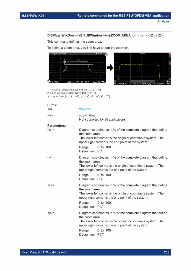
Remote commands for the R&S FSW OFDM VSA applicationR&S®FSW-K96
203User Manual 1179.3844.02 ─ 01
DISPlay[:WINDow<n>][:SUBWindow<w>]:ZOOM:AREA <x1>,<y1>,<x2>,<y2>
This command defines the zoom area.
To define a zoom area, you first have to turn the zoom on.
1 = origin of coordinate system (x1 = 0, y1 = 0)2 = end point of system (x2 = 100, y2= 100)3 = zoom area (e.g. x1 = 60, y1 = 30, x2 = 80, y2 = 75)
Suffix: <n>
.Window
<w> subwindowNot supported by all applications
Parameters:<x1> Diagram coordinates in % of the complete diagram that define
the zoom area.The lower left corner is the origin of coordinate system. Theupper right corner is the end point of the system.Range: 0 to 100Default unit: PCT
<y1> Diagram coordinates in % of the complete diagram that definethe zoom area.The lower left corner is the origin of coordinate system. Theupper right corner is the end point of the system.Range: 0 to 100Default unit: PCT
<x2> Diagram coordinates in % of the complete diagram that definethe zoom area.The lower left corner is the origin of coordinate system. Theupper right corner is the end point of the system.Range: 0 to 100Default unit: PCT
<y2> Diagram coordinates in % of the complete diagram that definethe zoom area.The lower left corner is the origin of coordinate system. Theupper right corner is the end point of the system.Range: 0 to 100Default unit: PCT
Analysis

Remote commands for the R&S FSW OFDM VSA applicationR&S®FSW-K96
204User Manual 1179.3844.02 ─ 01
DISPlay[:WINDow<n>][:SUBWindow<w>]:ZOOM[:STATe] <State>
This command turns the zoom on and off.
Suffix: <n>
.Window
<w> subwindowNot supported by all applications
Parameters:<State> ON | OFF | 0 | 1
OFF | 0Switches the function offON | 1Switches the function on
Example: DISP:ZOOM ONActivates the zoom mode.
8.6.5.2 Using the multiple zoom
DISPlay[:WINDow<n>][:SUBWindow<w>]:ZOOM:MULTiple<zn>:AREA...............................204DISPlay[:WINDow<n>][:SUBWindow<w>]:ZOOM:MULTiple<zn>[:STATe]............................ 205
DISPlay[:WINDow<n>][:SUBWindow<w>]:ZOOM:MULTiple<zn>:AREA<x1>,<y1>,<x2>,<y2>
This command defines the zoom area for a multiple zoom.
To define a zoom area, you first have to turn the zoom on.
1 = origin of coordinate system (x1 = 0, y1 = 0)2 = end point of system (x2 = 100, y2= 100)3 = zoom area (e.g. x1 = 60, y1 = 30, x2 = 80, y2 = 75)
Suffix: <n>
.Window
<w> subwindowNot supported by all applications
<zn> Selects the zoom window.
Analysis

Remote commands for the R&S FSW OFDM VSA applicationR&S®FSW-K96
205User Manual 1179.3844.02 ─ 01
Parameters:<x1> Diagram coordinates in % of the complete diagram that define
the zoom area.The lower left corner is the origin of coordinate system. Theupper right corner is the end point of the system.Range: 0 to 100Default unit: PCT
<y1> Diagram coordinates in % of the complete diagram that definethe zoom area.The lower left corner is the origin of coordinate system. Theupper right corner is the end point of the system.Range: 0 to 100Default unit: PCT
<x2> Diagram coordinates in % of the complete diagram that definethe zoom area.The lower left corner is the origin of coordinate system. Theupper right corner is the end point of the system.Range: 0 to 100Default unit: PCT
<y2> Diagram coordinates in % of the complete diagram that definethe zoom area.The lower left corner is the origin of coordinate system. Theupper right corner is the end point of the system.Range: 0 to 100Default unit: PCT
DISPlay[:WINDow<n>][:SUBWindow<w>]:ZOOM:MULTiple<zn>[:STATe] <State>
This command turns the multiple zoom on and off.
Suffix: <n>
.Window
<w> subwindowNot supported by all applications
<zn> Selects the zoom window.If you turn off one of the zoom windows, all subsequent zoomwindows move up one position.
Parameters:<State> ON | OFF | 0 | 1
OFF | 0Switches the function offON | 1Switches the function on
Analysis

Remote commands for the R&S FSW OFDM VSA applicationR&S®FSW-K96
206User Manual 1179.3844.02 ─ 01
8.7 Configuring the result display
The following commands are required to configure the result display in a remote envi-ronment.
● General window commands..................................................................................206● Working with windows in the display.....................................................................207
8.7.1 General window commands
The following commands are required to configure general window layout, independentof the application.
DISPlay:FORMat........................................................................................................... 206DISPlay[:WINDow<n>]:SIZE........................................................................................... 206
DISPlay:FORMat <Format>
This command determines which tab is displayed.
Parameters:<Format> SPLit
Displays the MultiView tab with an overview of all active chan-nelsSINGleDisplays the measurement channel that was previously focused.*RST: SING
Example: DISP:FORM SPL
DISPlay[:WINDow<n>]:SIZE <Size>
This command maximizes the size of the selected result display window temporarily.To change the size of several windows on the screen permanently, use the LAY:SPLcommand (see LAYout:SPLitter on page 210).
Suffix: <n>
.Window
Parameters:<Size> LARGe
Maximizes the selected window to full screen.Other windows are still active in the background.SMALlReduces the size of the selected window to its original size.If more than one measurement window was displayed originally,these are visible again.*RST: SMALl
Example: DISP:WIND2:SIZE LARG
Configuring the result display
Remote commands for the R&S FSW OFDM VSA applicationR&S®FSW-K96
207User Manual 1179.3844.02 ─ 01
8.7.2 Working with windows in the display
The following commands are required to change the evaluation type and rearrange thescreen layout for a channel as you do using the SmartGrid in manual operation. Sincethe available evaluation types depend on the selected application, some parametersfor the following commands also depend on the selected channel.
Note that the suffix <n> always refers to the window in the currently selected channel.
LAYout:ADD[:WINDow]?................................................................................................. 207LAYout:CATalog[:WINDow]?............................................................................................209LAYout:IDENtify[:WINDow]?............................................................................................ 209LAYout:REMove[:WINDow]............................................................................................. 210LAYout:REPLace[:WINDow]............................................................................................ 210LAYout:SPLitter..............................................................................................................210LAYout:WINDow<n>:ADD?............................................................................................. 212LAYout:WINDow<n>:IDENtify?........................................................................................ 212LAYout:WINDow<n>:REMove..........................................................................................213LAYout:WINDow<n>:REPLace........................................................................................ 213LAYout:WINDow<n>:TYPE..............................................................................................214
LAYout:ADD[:WINDow]? <WindowName>,<Direction>,<WindowType>
This command adds a window to the display in the active channel.
This command is always used as a query so that you immediately obtain the name ofthe new window as a result.
To replace an existing window, use the LAYout:REPLace[:WINDow] command.
Query parameters: <WindowName> String containing the name of the existing window the new win-
dow is inserted next to.By default, the name of a window is the same as its index. Todetermine the name and index of all active windows, use theLAYout:CATalog[:WINDow]? query.
<Direction> LEFT | RIGHt | ABOVe | BELowDirection the new window is added relative to the existing win-dow.
<WindowType> text valueType of result display (evaluation method) you want to add.See the table below for available parameter values.
Return values: <NewWindowName> When adding a new window, the command returns its name (by
default the same as its number) as a result.
Usage: Query only
Configuring the result display
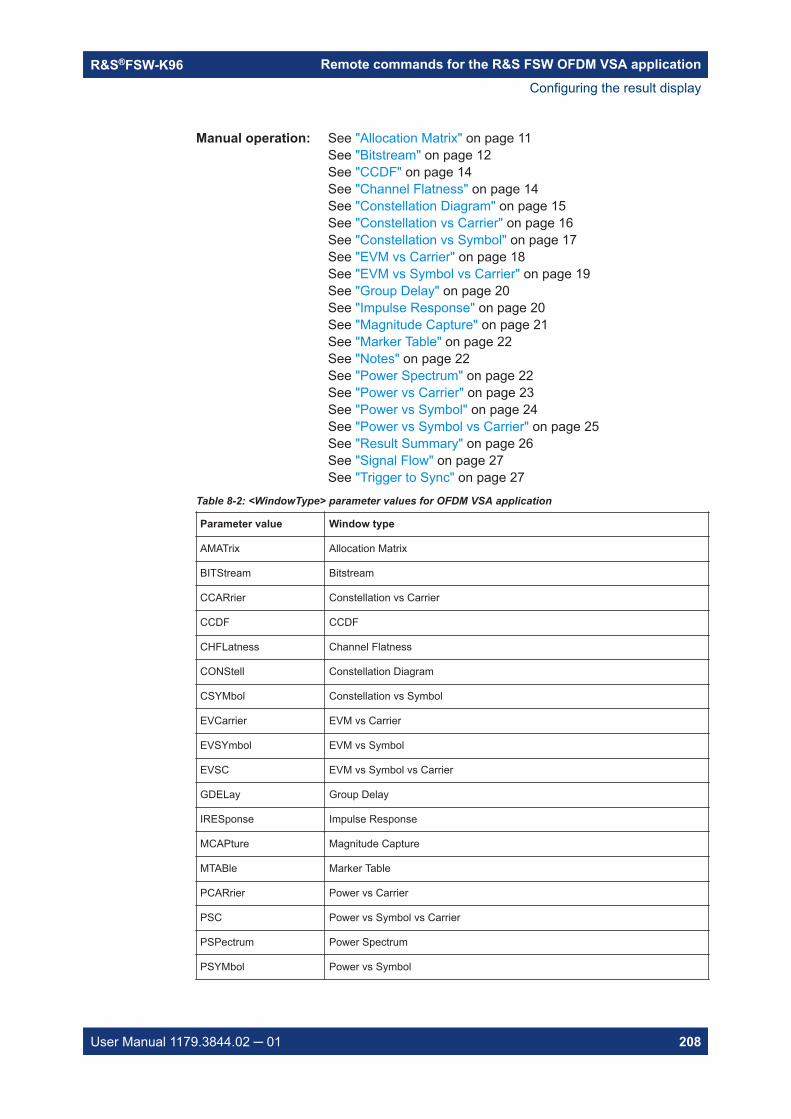
Remote commands for the R&S FSW OFDM VSA applicationR&S®FSW-K96
208User Manual 1179.3844.02 ─ 01
Manual operation: See "Allocation Matrix" on page 11See "Bitstream" on page 12See "CCDF" on page 14See "Channel Flatness" on page 14See "Constellation Diagram" on page 15See "Constellation vs Carrier" on page 16See "Constellation vs Symbol" on page 17See "EVM vs Carrier" on page 18See "EVM vs Symbol vs Carrier" on page 19See "Group Delay" on page 20See "Impulse Response" on page 20See "Magnitude Capture" on page 21See "Marker Table" on page 22See "Notes" on page 22See "Power Spectrum" on page 22See "Power vs Carrier" on page 23See "Power vs Symbol" on page 24See "Power vs Symbol vs Carrier" on page 25See "Result Summary" on page 26See "Signal Flow" on page 27See "Trigger to Sync" on page 27
Table 8-2: <WindowType> parameter values for OFDM VSA application
Parameter value Window type
AMATrix Allocation Matrix
BITStream Bitstream
CCARrier Constellation vs Carrier
CCDF CCDF
CHFLatness Channel Flatness
CONStell Constellation Diagram
CSYMbol Constellation vs Symbol
EVCarrier EVM vs Carrier
EVSYmbol EVM vs Symbol
EVSC EVM vs Symbol vs Carrier
GDELay Group Delay
IRESponse Impulse Response
MCAPture Magnitude Capture
MTABle Marker Table
PCARrier Power vs Carrier
PSC Power vs Symbol vs Carrier
PSPectrum Power Spectrum
PSYMbol Power vs Symbol
Configuring the result display

Remote commands for the R&S FSW OFDM VSA applicationR&S®FSW-K96
209User Manual 1179.3844.02 ─ 01
Parameter value Window type
RSUMmary Result Summary
SFLow Signal Flow
TRIGger Trigger to Sync
LAYout:CATalog[:WINDow]?
This command queries the name and index of all active windows in the active channelfrom top left to bottom right. The result is a comma-separated list of values for eachwindow, with the syntax:
<WindowName_1>,<WindowIndex_1>..<WindowName_n>,<WindowIndex_n>
Return values: <WindowName> string
Name of the window.In the default state, the name of the window is its index.
<WindowIndex> numeric valueIndex of the window.
Example: LAY:CAT?Result:'2',2,'1',1Two windows are displayed, named '2' (at the top or left), and '1'(at the bottom or right).
Usage: Query only
LAYout:IDENtify[:WINDow]? <WindowName>
This command queries the index of a particular display window in the active channel.
Note: to query the name of a particular window, use the LAYout:WINDow<n>:IDENtify? query.
Query parameters: <WindowName> String containing the name of a window.
Return values: <WindowIndex> Index number of the window.
Example: LAY:WIND:IDEN? '2'Queries the index of the result display named '2'.Response:2
Usage: Query only
Configuring the result display
Remote commands for the R&S FSW OFDM VSA applicationR&S®FSW-K96
210User Manual 1179.3844.02 ─ 01
LAYout:REMove[:WINDow] <WindowName>
This command removes a window from the display in the active channel.
Setting parameters: <WindowName> String containing the name of the window. In the default state,
the name of the window is its index.
Example: LAY:REM '2'Removes the result display in the window named '2'.
Usage: Setting only
LAYout:REPLace[:WINDow] <WindowName>,<WindowType>
This command replaces the window type (for example from "Diagram" to "Result Sum-mary") of an already existing window in the active channel while keeping its position,index and window name.
To add a new window, use the LAYout:ADD[:WINDow]? command.
Setting parameters: <WindowName> String containing the name of the existing window.
By default, the name of a window is the same as its index. Todetermine the name and index of all active windows in the activechannel, use the LAYout:CATalog[:WINDow]? query.
<WindowType> Type of result display you want to use in the existing window.See LAYout:ADD[:WINDow]? on page 207 for a list of availa-ble window types.
Example: LAY:REPL:WIND '1',MTABReplaces the result display in window 1 with a marker table.
Usage: Setting only
LAYout:SPLitter <Index1>, <Index2>, <Position>
This command changes the position of a splitter and thus controls the size of the win-dows on each side of the splitter.
Compared to the DISPlay[:WINDow<n>]:SIZE on page 206 command, theLAYout:SPLitter changes the size of all windows to either side of the splitter per-manently, it does not just maximize a single window temporarily.
Note that windows must have a certain minimum size. If the position you define con-flicts with the minimum size of any of the affected windows, the command will not work,but does not return an error.
Configuring the result display
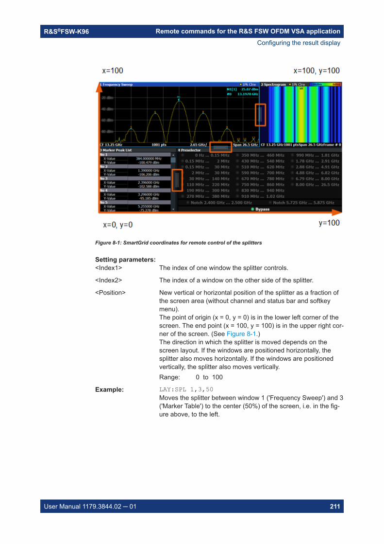
Remote commands for the R&S FSW OFDM VSA applicationR&S®FSW-K96
211User Manual 1179.3844.02 ─ 01
Figure 8-1: SmartGrid coordinates for remote control of the splitters
Setting parameters: <Index1> The index of one window the splitter controls.
<Index2> The index of a window on the other side of the splitter.
<Position> New vertical or horizontal position of the splitter as a fraction ofthe screen area (without channel and status bar and softkeymenu).The point of origin (x = 0, y = 0) is in the lower left corner of thescreen. The end point (x = 100, y = 100) is in the upper right cor-ner of the screen. (See Figure 8-1.)The direction in which the splitter is moved depends on thescreen layout. If the windows are positioned horizontally, thesplitter also moves horizontally. If the windows are positionedvertically, the splitter also moves vertically.Range: 0 to 100
Example: LAY:SPL 1,3,50Moves the splitter between window 1 ('Frequency Sweep') and 3('Marker Table') to the center (50%) of the screen, i.e. in the fig-ure above, to the left.
Configuring the result display

Remote commands for the R&S FSW OFDM VSA applicationR&S®FSW-K96
212User Manual 1179.3844.02 ─ 01
Example: LAY:SPL 1,4,70Moves the splitter between window 1 ('Frequency Sweep') and 3('Marker Peak List') towards the top (70%) of the screen.The following commands have the exact same effect, as anycombination of windows above and below the splitter moves thesplitter vertically.LAY:SPL 3,2,70LAY:SPL 4,1,70LAY:SPL 2,1,70
Usage: Setting only
LAYout:WINDow<n>:ADD? <Direction>,<WindowType>
This command adds a measurement window to the display. Note that with this com-mand, the suffix <n> determines the existing window next to which the new window isadded, as opposed to LAYout:ADD[:WINDow]?, for which the existing window isdefined by a parameter.
To replace an existing window, use the LAYout:WINDow<n>:REPLace command.
This command is always used as a query so that you immediately obtain the name ofthe new window as a result.
Suffix: <n>
.Window
Query parameters: <Direction> LEFT | RIGHt | ABOVe | BELow
<WindowType> Type of measurement window you want to add.See LAYout:ADD[:WINDow]? on page 207 for a list of availa-ble window types.
Return values: <NewWindowName> When adding a new window, the command returns its name (by
default the same as its number) as a result.
Example: LAY:WIND1:ADD? LEFT,MTABResult:'2'Adds a new window named '2' with a marker table to the left ofwindow 1.
Usage: Query only
LAYout:WINDow<n>:IDENtify?
This command queries the name of a particular display window (indicated by the <n>suffix) in the active channel.
Note: to query the index of a particular window, use the LAYout:IDENtify[:WINDow]? command.
Configuring the result display

Remote commands for the R&S FSW OFDM VSA applicationR&S®FSW-K96
213User Manual 1179.3844.02 ─ 01
Suffix: <n>
.Window
Return values: <WindowName> String containing the name of a window.
In the default state, the name of the window is its index.
Example: LAY:WIND2:IDEN?Queries the name of the result display in window 2.Response:'2'
Usage: Query only
LAYout:WINDow<n>:REMove
This command removes the window specified by the suffix <n> from the display in theactive channel.
The result of this command is identical to the LAYout:REMove[:WINDow] command.
Suffix: <n>
.Window
Example: LAY:WIND2:REMRemoves the result display in window 2.
Usage: Event
LAYout:WINDow<n>:REPLace <WindowType>
This command changes the window type of an existing window (specified by the suffix<n>) in the active channel.
The effect of this command is identical to the LAYout:REPLace[:WINDow] com-mand.
To add a new window, use the LAYout:WINDow<n>:ADD? command.
Suffix: <n>
.Window
Setting parameters: <WindowType> Type of measurement window you want to replace another one
with.See LAYout:ADD[:WINDow]? on page 207 for a list of availa-ble window types.
Example: LAY:WIND2:REPL MTABReplaces the result display in window 2 with a marker table.
Usage: Setting only
Configuring the result display

Remote commands for the R&S FSW OFDM VSA applicationR&S®FSW-K96
214User Manual 1179.3844.02 ─ 01
LAYout:WINDow<n>:TYPE <WindowType>
Queries or defines the window type of the window specified by the index <n>. The win-dow type determines which results are displayed. For a list of possible window typessee LAYout:ADD[:WINDow]? on page 207.
Note this command is not available in all applications and measurements.
Suffix: <n>
.1..nWindow
Parameters:<WindowType>
Example: LAY:WIND2:TYPE?
8.8 Retrieving results
The following commands are required to retrieve the calculated OFDM VSA parame-ters.
● Retrieving numerical results..................................................................................214● Retrieving signal flow results.................................................................................218● Retrieving trace data and marker values.............................................................. 222● Using the TRACe[:DATA] command..................................................................... 231
8.8.1 Retrieving numerical results
These commands return the average, maximum or minimum result of the specifiedparameter. For details and an assignment of the parameters to the keywords see
FETCh:BURSt:COUNt?.................................................................................................. 215FETCh:BURSt:LENGths?............................................................................................... 215FETCh:BURSt:STARts?..................................................................................................216FETCh:SUMMary[:ALL]?................................................................................................ 216FETCh:SUMMary:CRESt:MAXimum?.............................................................................. 217FETCh:SUMMary:CRESt:MINimum?............................................................................... 217FETCh:SUMMary:CRESt[:AVERage]?............................................................................. 217FETCh:SUMMary:EVM:DATA:MAXimum?........................................................................ 217FETCh:SUMMary:EVM:DATA:MINimum?......................................................................... 217FETCh:SUMMary:EVM:DATA[:AVERage]?....................................................................... 217FETCh:SUMMary:EVMPeak:DATA:MAXimum*?............................................................... 217FETCh:SUMMary:EVMPeak:DATA:PCT:MAXimum*?........................................................ 217FETCh:SUMMary:EVMPeak:PILot:MAXimum*?................................................................ 217FETCh:SUMMary:EVMPeak:PILot:PCT:MAXimum*?......................................................... 217FETCh:SUMMary:EVMPeak[:ALL]:MAXimum*?................................................................ 217FETCh:SUMMary:EVMPeak[:ALL]:PCT:MAXimum*?......................................................... 217FETCh:SUMMary:EVM:PILot:MAXimum?.........................................................................217FETCh:SUMMary:EVM:PILot:MINimum?..........................................................................217
Retrieving results

Remote commands for the R&S FSW OFDM VSA applicationR&S®FSW-K96
215User Manual 1179.3844.02 ─ 01
FETCh:SUMMary:EVM:PILot[:AVERage]?........................................................................217FETCh:SUMMary:EVM:PILot:PCT[:AVERage]?................................................................ 217FETCh:SUMMary:EVM[:ALL]:MAXimum?.........................................................................217FETCh:SUMMary:EVM[:ALL]:MINimum?..........................................................................217FETCh:SUMMary:EVM[:ALL][:AVERage]?........................................................................217FETCh:SUMMary:EVM[:ALL]:PCT:MAXimum?..................................................................217FETCh:SUMMary:EVM[:ALL]:PCT:MINimum?...................................................................217FETCh:SUMMary:EVM[:ALL]:PCT[:AVERage]?................................................................ 217FETCh:SUMMary:FERRor:MAXimum?............................................................................ 217FETCh:SUMMary:FERRor:MINimum?..............................................................................217FETCh:SUMMary:FERRor[:AVERage]?............................................................................217FETCh:SUMMary:GIMBalance:MAXimum?...................................................................... 217FETCh:SUMMary:GIMBalance:MINimum?....................................................................... 217FETCh:SUMMary:GIMBalance[:AVERage]?..................................................................... 217FETCh:SUMMary:IQOFfset:MAXimum?........................................................................... 217FETCh:SUMMary:IQOFfset:MINimum?............................................................................ 217FETCh:SUMMary:IQOFfset[:AVERage]?.......................................................................... 218FETCh:SUMMary:MER[:ALL]:MAXimum?........................................................................ 218FETCh:SUMMary:MER[:ALL]:MINimum?..........................................................................218FETCh:SUMMary:MER[:ALL][:AVERage]?........................................................................218FETCh:SUMMary:POWer:MAXimum?..............................................................................218FETCh:SUMMary:POWer:MINimum?...............................................................................218FETCh:SUMMary:POWer[:AVERage]?.............................................................................218FETCh:SUMMary:QUADerror:MAXimum?........................................................................218FETCh:SUMMary:QUADerror:MINimum?......................................................................... 218FETCh:SUMMary:QUADerror[:AVERage]?....................................................................... 218FETCh:SUMMary:SERRor:MAXimum?............................................................................ 218FETCh:SUMMary:SERRor:MINimum?............................................................................. 218FETCh:SUMMary:SERRor[:AVERage]?........................................................................... 218FETCh:SUMM:<parameter>:<statistic>............................................................................ 218FETCh:TTFRame?.........................................................................................................218
FETCh:BURSt:COUNt?
This command returns the number of analyzed bursts from the current capture buffer.
Return values: <Value>
Usage: Query only
FETCh:BURSt:LENGths?
This command returns the length of the analyzed bursts from the current measure-ment.
The result is a comma-separated list of lengths, one for each burst.
Return values: <Value> Default unit: s
Usage: Query only
Retrieving results

Remote commands for the R&S FSW OFDM VSA applicationR&S®FSW-K96
216User Manual 1179.3844.02 ─ 01
FETCh:BURSt:STARts?
This command returns the start position of each analyzed burst in the current capturebuffer.
Return values: <Value> Offset of the burst start from the beginning of the capture buffer.
Default unit: s
Example: FETC:BURS:STAR?//Result://6.04e-05
Usage: Query only
FETCh:SUMMary[:ALL]?
Returns all values in the result summary, in the same order as in the display
(See "Result Summary" on page 26.)
Return values: <Result> <EVMAll_dB_Min>,<EVMAll_dB_Avg>,<EVMAll_dB_Max>,
<EVMAll_PCT_Min>,<EVMAll_PCT_Avg>,<EVMAll_PCT_Max>, <EVMData_dB_Min>,<EVMData_dB_Avg>,<EVM-Data_dB_Max>, <EVMData_PCT_Min>,<EVM-Data_PCT_Avg>,<EVMData_PCT_Max>, <EVMPi-lot_dB_Min>,<EVMPilot_dB_Avg>,<EVMPilot_dB_Max>, <EVM-Pilot_PCT_Min>,<EVMPilot_PCT_Avg>,<EVMPilot_PCT_Max>,<MER_Min>,<MER_Avg>,<MER_Max>, <I/QOffset_Min>,<I/QOffset_Avg>,<I/QOffset_Max>, <GainImbalance_Min>,<Gain-Imbalance_Avg>,<GainImbalance_Max>, <QuadEr-ror_Min>,<QuadError_Avg>,<QuadError_Max>, <Fre-qErr_Min>,<FreqErr_Avg>,<FreqErr_Max>, <SampleClock-Err_Min>,<SampleClockErr_Avg>,<SampleClockErr_Max>,<FramePower_Min>,<FramePower_Avg>,<FramePower_Max>,<CrestFactor_Min>,<CrestFactor_Avg>,<CrestFactor_Max>,Comma-separated list with 3 statistical values for each result.
Retrieving results

Remote commands for the R&S FSW OFDM VSA applicationR&S®FSW-K96
217User Manual 1179.3844.02 ─ 01
Example: FETC:SUMM:ALL?//-34.6742,-34.6742,-34.6742,//1.84624,1.84624,1.84624,//-34.5875,-34.5875,-34.5875,//1.86477,1.86477,1.86477,//-35.5229,-35.5229,-35.5229,//1.67439,1.67439,1.67439,//34.6742,34.6742,34.6742,//-75.106,-75.106,-75.106,//0.00573547,0.00573547,0.00573547,//-0.0159425,-0.0159425,-0.0159425,//0.272241,0.272241,0.272241,//0.219516,0.219516,0.219516,//-23.1036,-23.1036,-23.1036,//9.84252,9.84252,9.84252
Usage: Query only
Manual operation: See "Result Summary" on page 26
FETCh:SUMMary:CRESt:MAXimum?FETCh:SUMMary:CRESt:MINimum?FETCh:SUMMary:CRESt[:AVERage]?FETCh:SUMMary:EVM:DATA:MAXimum?FETCh:SUMMary:EVM:DATA:MINimum?FETCh:SUMMary:EVM:DATA[:AVERage]?FETCh:SUMMary:EVMPeak:DATA:MAXimum*?FETCh:SUMMary:EVMPeak:DATA:PCT:MAXimum*?FETCh:SUMMary:EVMPeak:PILot:MAXimum*?FETCh:SUMMary:EVMPeak:PILot:PCT:MAXimum*?FETCh:SUMMary:EVMPeak[:ALL]:MAXimum*?FETCh:SUMMary:EVMPeak[:ALL]:PCT:MAXimum*?FETCh:SUMMary:EVM:PILot:MAXimum?FETCh:SUMMary:EVM:PILot:MINimum?FETCh:SUMMary:EVM:PILot[:AVERage]?FETCh:SUMMary:EVM:PILot:PCT[:AVERage]?FETCh:SUMMary:EVM[:ALL]:MAXimum?FETCh:SUMMary:EVM[:ALL]:MINimum?FETCh:SUMMary:EVM[:ALL][:AVERage]?FETCh:SUMMary:EVM[:ALL]:PCT:MAXimum?FETCh:SUMMary:EVM[:ALL]:PCT:MINimum?FETCh:SUMMary:EVM[:ALL]:PCT[:AVERage]?FETCh:SUMMary:FERRor:MAXimum?FETCh:SUMMary:FERRor:MINimum?FETCh:SUMMary:FERRor[:AVERage]?FETCh:SUMMary:GIMBalance:MAXimum?FETCh:SUMMary:GIMBalance:MINimum?FETCh:SUMMary:GIMBalance[:AVERage]?FETCh:SUMMary:IQOFfset:MAXimum?FETCh:SUMMary:IQOFfset:MINimum?
Retrieving results

Remote commands for the R&S FSW OFDM VSA applicationR&S®FSW-K96
218User Manual 1179.3844.02 ─ 01
FETCh:SUMMary:IQOFfset[:AVERage]?FETCh:SUMMary:MER[:ALL]:MAXimum?FETCh:SUMMary:MER[:ALL]:MINimum?FETCh:SUMMary:MER[:ALL][:AVERage]?FETCh:SUMMary:POWer:MAXimum?FETCh:SUMMary:POWer:MINimum?FETCh:SUMMary:POWer[:AVERage]?FETCh:SUMMary:QUADerror:MAXimum?FETCh:SUMMary:QUADerror:MINimum?FETCh:SUMMary:QUADerror[:AVERage]?FETCh:SUMMary:SERRor:MAXimum?FETCh:SUMMary:SERRor:MINimum?FETCh:SUMMary:SERRor[:AVERage]?FETCh:SUMM:<parameter>:<statistic>These commands return the average, maximum or minimum result of the specifiedparameter. For details and an assignment of the parameters to the keywords seeTable 2-1.
*) These results are not included in the Result Summary display, nor in the FETCh:SUMMary[:ALL]? results.
FETCh:TTFRame?
Retrieves the time offset between the trigger event and the start of the first OFDMframe.
Return values: <Time>
Example: FETC:TTFR?Usage: Query only
Manual operation: See "Trigger to Sync" on page 27
8.8.2 Retrieving signal flow results
The following commands are required to retrieve the results of the signal flow stages.See also "Signal Flow" on page 27.
FETCh:SFLow:FSYNc?.................................................................................................. 219FETCh:SFLow:STATe:ALL?............................................................................................ 219FETCh:SFLow:STATe:BDETection?................................................................................. 219FETCh:SFLow:STATe:COMPensate?...............................................................................220FETCh:SFLow:STATe:DESTimation?............................................................................... 220FETCh:SFLow:STATe:EVMMeas?................................................................................... 220FETCh:SFLow:STATe:FSYNc?........................................................................................221FETCh:SFLow:STATe:MDETection?.................................................................................221FETCh:SFLow:STATe:PESTimation?............................................................................... 221FETCh:SFLow:STATe:TSYNc?........................................................................................222FETCh:SFLow:TSYNc?.................................................................................................. 222
Retrieving results
Remote commands for the R&S FSW OFDM VSA applicationR&S®FSW-K96
219User Manual 1179.3844.02 ─ 01
FETCh:SFLow:FSYNc?
This command returns the Frame Synchronisation value.
Return values: <Value>
Example: FETC:SFL:FSYN?Usage: Query only
FETCh:SFLow:STATe:ALL?
Returns the state of the individual stages of the signal flow. The result is a comma-sep-arated list of states, one for each stage. The stages are in the following order:
● Burst Detection● Time Sync● Frame Sync● Data-Aided Parameter estimation● Modulation detection● Pilot-aided parameter estimation● Compensate● EVM meas
Return values: <Value> 0
Not successful1Successful-1Inactive
Example: FETC:SFL:STAT:ALL?Usage: Query only
FETCh:SFLow:STATe:BDETection?
Returns the state of the burst detection stage of the signal flow.
Return values: <Value> 0
Not successful1Successful-1Inactive
Example: FETC:SFL:STAT:BDET?
Retrieving results

Remote commands for the R&S FSW OFDM VSA applicationR&S®FSW-K96
220User Manual 1179.3844.02 ─ 01
Usage: Query only
FETCh:SFLow:STATe:COMPensate?
Returns the state of the compensation stage of the signal flow.
Return values: <Value> 0
Not successful1Successful-1Inactive
Example: FETC:SFL:STAT:COMP?Usage: Query only
FETCh:SFLow:STATe:DESTimation?
Returns the state of the data-aided parameter estimation stage of the signal flow.
Return values: <Value> 0
Not successful1Successful-1Inactive
Example: FETC:SFL:STAT:DEST?Usage: Query only
FETCh:SFLow:STATe:EVMMeas?
Returns the state of the EVM measurement stage of the signal flow.
Return values: <Value> 0
Not successful1Successful-1Inactive
Example: FETC:SFL:STAT:EVMM?Usage: Query only
Retrieving results
Remote commands for the R&S FSW OFDM VSA applicationR&S®FSW-K96
221User Manual 1179.3844.02 ─ 01
FETCh:SFLow:STATe:FSYNc?
Returns the state of the frame synchronization stage of the signal flow.
Return values: <Value> 0
Not successful1Successful-1Inactive
Example: FETC:SFL:STAT:FSYN?Usage: Query only
FETCh:SFLow:STATe:MDETection?
Returns the state of the modulation detection stage of the signal flow.
Return values: <Value> 0
Not successful1Successful-1Inactive
Example: FETC:SFL:STAT:MDET?Usage: Query only
FETCh:SFLow:STATe:PESTimation?
Returns the state of the pilot-aided parameter estimation stage of the signal flow.
Return values: <Value> 0
Not successful1Successful-1Inactive
Example: FETC:SFL:STAT:PEST?Usage: Query only
Retrieving results

Remote commands for the R&S FSW OFDM VSA applicationR&S®FSW-K96
222User Manual 1179.3844.02 ─ 01
FETCh:SFLow:STATe:TSYNc?
Returns the state of the time synchronization stage of the signal flow.
Return values: <Value> 0
Not successful1Successful-1Inactive
Example: FETC:SFL:STAT:TSYN?Usage: Query only
FETCh:SFLow:TSYNc?
This command returns the Time Synchronisation value.
Return values: <Value>
Example: FETC:SFL:TSYN?Usage: Query only
8.8.3 Retrieving trace data and marker values
In order to retrieve the trace and marker results in a remote environment, use the fol-lowing commands:
Useful commands for retrieving results described elsewhere:● CALCulate<n>:MARKer<m>:X on page 193
Remote commands exclusive to retrieving trace data and marker values:
CALCulate<n>:DELTamarker<m>:Y?............................................................................... 223CALCulate<n>:DELTamarker<m>:Y:RELative?................................................................. 223CALCulate<n>:DELTamarker<m>:Z................................................................................. 223CALCulate<n>:MARKer<m>:Y?.......................................................................................224CALCulate<n>:MARKer<m>:Z.........................................................................................224FORMat[:DATA]............................................................................................................. 225FORMat:DEXPort:DSEParator........................................................................................ 226FORMat:DEXPort:GRAPh...............................................................................................226FORMat:DEXPort:HEADer..............................................................................................226FORMat:DEXPort:TRACes............................................................................................. 227FORMat:DEXPort:XDIStrib..............................................................................................227MMEMory:STORe<n>:TRACe.........................................................................................227TRACe<n>[:DATA]?....................................................................................................... 228TRACe<n>[:DATA]:X?.................................................................................................... 228TRACe<n>[:DATA]:Y?.................................................................................................... 229
Retrieving results

Remote commands for the R&S FSW OFDM VSA applicationR&S®FSW-K96
223User Manual 1179.3844.02 ─ 01
TRACe:IQ:DATA?.......................................................................................................... 229TRACe:IQ:DATA:FORMat............................................................................................... 230TRACe:IQ:DATA:MEMory?............................................................................................. 230
CALCulate<n>:DELTamarker<m>:Y?
Queries the result at the position of the specified delta marker.
Suffix: <n>
.1..n
<m> 1..n
Return values: <Result> Result at the position of the delta marker.
The unit is variable and depends on the one you have currentlyset.Default unit: DBM
Usage: Query only
Manual operation: See "Y-Value" on page 125
CALCulate<n>:DELTamarker<m>:Y:RELative?
This command queries the relative position of a delta marker of a 3D trace on the y-axis. If necessary, the command activates the delta marker first.
Suffix: <n>
.Window
<m> Marker
Return values: <XValue> Default unit: HZ
Example: CALC:DELT3:Y:REL?Usage: Query only
CALCulate<n>:DELTamarker<m>:Z <Result>
This command sets a delta marker's current position on the z-axis or queries its resultin a 3-dimensional diagram.
Suffix: <n>
.Window
<m> Marker
Retrieving results

Remote commands for the R&S FSW OFDM VSA applicationR&S®FSW-K96
224User Manual 1179.3844.02 ─ 01
Parameters:<Result> Result at the position of the delta marker.
For 3-dimensional constellation diagrams (Constellation vs car-rier/symbol), this parameter defines the carrier or symbol,respectively, to place the marker at.The unit depends on the type of data displayed on the z-axis.
Example: //Define a power vs. symbol vs. carrier displayLAY:ADD? '1',RIGH,PSC//Set delta marker 2 at carrier 2CALC2:DELT2:Y 2//Query the delta marker result for carrier 2CALC2:DELT2:Z?
Example: //Define constellation vs. symbol displayLAY:ADD? '1',RIGH,CSYM//Set delta marker 2 at carrier 1CALC2:DELT2:Z 1//Query the delta marker result for carrier 1.CAL2:DELT2:Y?
CALCulate<n>:MARKer<m>:Y?
Queries the result at the position of the specified marker.
Suffix: <n>
.1..n
<m> 1..n
Return values: <Result> Default unit: DBM
Usage: Query only
Manual operation: See "Marker Table" on page 22See "Y-Value" on page 125
CALCulate<n>:MARKer<m>:Z <Result>
This command sets a marker's current position on the z-axis or queries its result in a 3-dimensional diagram.
Suffix: <n>
.Window
<m> Marker
Parameters:<Result> Result at the position of the marker.
For 3-dimensional constellation diagrams (Constellation vs car-rier/symbol), this parameter defines the carrier or symbol,respectively, to place the marker at.The unit depends on the type of data displayed on the z-axis.
Retrieving results

Remote commands for the R&S FSW OFDM VSA applicationR&S®FSW-K96
225User Manual 1179.3844.02 ─ 01
Example: //Define a power vs. symbol vs. carrier displayLAY:ADD? '1',RIGH,PSC//Set marker 2 at carrier 2CALC2:MARK2:Y 2//Query the marker result for carrier 2CALC2:MARK2:Z?
Example: //Define constellation vs. carrier displayLAY:ADD? '1',RIGH,CCAR//Set marker 2 at symbol 3CALC2:MARK2:Z 3//Query the marker result for symbol 3.CAL2:MARK2:Y?
Manual operation: See "Constellation Diagram" on page 15See "Constellation vs Carrier" on page 16See "Constellation vs Symbol" on page 17See "EVM vs Symbol vs Carrier" on page 19See "Power vs Symbol vs Carrier" on page 25
FORMat[:DATA] <Format>[, <BitLength>]
This command selects the data format that is used for transmission of trace data fromthe R&S FSW to the controlling computer.
Note that the command has no effect for data that you send to the R&S FSW. TheR&S FSW automatically recognizes the data it receives, regardless of the format.
Parameters:<Format> ASCii
ASCii format, separated by commas.This format is almost always suitable, regardless of the actualdata format. However, the data is not as compact as other for-mats may be.REALFloating-point numbers (according to IEEE 754) in the "definitelength block format".In the Spectrum application, the format setting REAL is used forthe binary transmission of trace data.
<BitLength> Length in bits for floating-point results1616-bit floating-point numbers.Compared to REAL,32 format, half as many numbers arereturned.3232-bit floating-point numbersFor I/Q data, 8 bytes per sample are returned for this format set-ting.
Retrieving results

Remote commands for the R&S FSW OFDM VSA applicationR&S®FSW-K96
226User Manual 1179.3844.02 ─ 01
6464-bit floating-point numbersCompared to REAL,32 format, twice as many numbers arereturned.
Example: FORM REAL,32
FORMat:DEXPort:DSEParator <Separator>
This command selects the decimal separator for data exported in ASCII format.
Parameters:<Separator> POINt | COMMa
COMMaUses a comma as decimal separator, e.g. 4,05.POINtUses a point as decimal separator, e.g. 4.05.*RST: *RST has no effect on the decimal separator.
Default is POINt.
Example: FORM:DEXP:DSEP POINSets the decimal point as separator.
Manual operation: See "Decimal Separator" on page 130
FORMat:DEXPort:GRAPh <State>
If enabled, all traces for the currently selected graphical result display are included inthe export file.
Parameters:<State> ON | OFF | 0 | 1
OFF | 0Switches the function offON | 1Switches the function on*RST: 0
Manual operation: See "Export All Traces for Selected Graph" on page 129
FORMat:DEXPort:HEADer <State>
If enabled, additional instrument and measurement settings are included in the headerof the export file for result data. If disabled, only the pure result data from the selectedtraces and tables is exported.
Parameters:<State> ON | OFF | 0 | 1
*RST: 1
Manual operation: See "Include Instrument & Measurement Settings" on page 129
Retrieving results

Remote commands for the R&S FSW OFDM VSA applicationR&S®FSW-K96
227User Manual 1179.3844.02 ─ 01
FORMat:DEXPort:TRACes <Selection>
This command selects the data to be included in a data export file (see MMEMory:STORe<n>:TRACe on page 227).
Parameters:<Selection> SINGle | ALL
SINGleOnly a single trace is selected for export, namely the one speci-fied by the MMEMory:STORe<n>:TRACe command.ALLSelects all active traces and result tables (e.g. Result Summary,marker peak list etc.) in the current application for export to anASCII file.The <trace> parameter for the MMEMory:STORe<n>:TRACecommand is ignored.*RST: SINGle
Manual operation: See "Export all Traces and all Table Results" on page 129
FORMat:DEXPort:XDIStrib <XDistribution>
Defines how the x-values of the trace are determined in the frequency domain.
Parameters:<XDistribution> STARtstop | BINCentered
BINCenteredThe full measurement span is divided by the number of mea-surement points to obtain bins. The x-value of the measurementpoint is defined as the x-value at the center of the bin (bin/2).STARtstop(Default): The x-value of the first measurement point corre-sponds to the starting point of the full measurement span. The x-value of the last measurement point corresponds to the endpoint of the full measurement span. All other measurementpoints are divided evenly between the first and last points.
Example: FORM:DEXP:XDIS BINC
MMEMory:STORe<n>:TRACe <Trace>, <FileName>
This command exports trace data from the specified window to an ASCII file.
For details on the order of the trace results depending on the display type, see Chap-ter 8.8.4, "Using the TRACe[:DATA] command", on page 231.
Secure User Mode
In secure user mode, settings that are stored on the instrument are stored to volatilememory, which is restricted to 256 MB. Thus, a "memory limit reached" error can occuralthough the hard disk indicates that storage space is still available.
Retrieving results

Remote commands for the R&S FSW OFDM VSA applicationR&S®FSW-K96
228User Manual 1179.3844.02 ─ 01
To store data permanently, select an external storage location such as a USB memorydevice.
For details, see "Protecting Data Using the Secure User Mode" in the "Data Manage-ment" section of the R&S FSW base unit user manual.
Suffix: <n>
.Window
Parameters:<Trace> Number of the trace to be stored
<FileName> String containing the path and name of the target file.
Example: MMEM:STOR1:TRAC 1,'C:\TEST.ASC'Stores trace 1 from window 1 in the file TEST.ASC.
Manual operation: See "Export Trace to ASCII File" on page 130
TRACe<n>[:DATA]? <Trace>
This command returns the y-values of the trace data for the current measurement orresult display.
For 3-dimensional displays, such as the Allocation Matrix, this command returns thedata values for the third (z-) dimension.
For more information see Chapter 8.8.4, "Using the TRACe[:DATA] command",on page 231.
Suffix: <n>
.1..nWindow
Query parameters: <Trace> TRACE1 | TRACE2 | TRACE3 | TRACE4 | TRACE5 | TRACE6
Usage: Query only
Manual operation: See "Allocation Matrix" on page 11
TRACe<n>[:DATA]:X? [<Trace>]
This command returns the x-values for the trace data in the selected result display.
For information on how many values are returned see Chapter 8.8.4, "Using theTRACe[:DATA] command", on page 231.
Suffix: <n>
.1..nWindow
Query parameters: <Trace> TRACE1 | TRACE2 | TRACE3 | TRACE4 | TRACE5 | TRACE6
Example: TRAC2:DATA:X?
Retrieving results

Remote commands for the R&S FSW OFDM VSA applicationR&S®FSW-K96
229User Manual 1179.3844.02 ─ 01
Usage: Query only
Manual operation: See "Allocation Matrix" on page 11See "CCDF" on page 14See "Channel Flatness" on page 14See "EVM vs Carrier" on page 18See "EVM vs Symbol vs Carrier" on page 19See "Group Delay" on page 20See "Impulse Response" on page 20See "Magnitude Capture" on page 21See "Power vs Carrier" on page 23See "Power vs Symbol" on page 24See "Power vs Symbol vs Carrier" on page 25
TRACe<n>[:DATA]:Y? [<Trace>]
This command returns the y-values for 3-dimensional trace data in the selected resultdisplay.
For information on how many values are returned see Chapter 8.8.4, "Using theTRACe[:DATA] command", on page 231.
Suffix: <n>
.1..nWindow
Query parameters: <Trace>
Example: TRAC2:DATA:Y?Usage: Query only
Manual operation: See "Allocation Matrix" on page 11See "EVM vs Symbol vs Carrier" on page 19See "Power vs Symbol vs Carrier" on page 25
TRACe:IQ:DATA?
This command initiates a measurement with the current settings and returns the cap-tured data from I/Q measurements.
This command corresponds to:
INIT:IMM;*WAI;:TRACe:IQ:DATA:MEMory?However, the TRACe:IQ:DATA? command is quicker in comparison.
Return values: <Results> Measured voltage for I and Q component for each sample that
has been captured during the measurement.Default unit: V
Retrieving results

Remote commands for the R&S FSW OFDM VSA applicationR&S®FSW-K96
230User Manual 1179.3844.02 ─ 01
Example: TRAC:IQ:STAT ONEnables acquisition of I/Q dataTRAC:IQ:SET NORM,10MHz,32MHz,EXT,POS,0,4096Measurement configuration:Sample Rate = 32 MHzTrigger Source = ExternalTrigger Slope = PositivePretrigger Samples = 0Number of Samples = 4096FORMat REAL,32Selects format of response dataTRAC:IQ:DATA?Starts measurement and reads results
Usage: Query only
TRACe:IQ:DATA:FORMat <Format>
This command selects the order of the I/Q data.
Parameters:<Format> COMPatible | IQBLock | IQPair
COMPatibleI and Q values are separated and collected in blocks: A block(512k) of I values is followed by a block (512k) of Q values, fol-lowed by a block of I values, followed by a block of Q values etc.(I,I,I,I,Q,Q,Q,Q,I,I,I,I,Q,Q,Q,Q...)IQBLockFirst all I-values are listed, then the Q-values(I,I,I,I,I,I,...Q,Q,Q,Q,Q,Q)IQPairOne pair of I/Q values after the other is listed(I,Q,I,Q,I,Q...).*RST: IQBL
TRACe:IQ:DATA:MEMory? [<OffsetSamples>,<NoOfSamples>]
This command queries the I/Q data currently stored in the capture buffer of theR&S FSW.
By default, the command returns all I/Q data in the memory. You can, however, narrowdown the amount of data that the command returns using the optional parameters.
If no parameters are specified with the command, the entire trace data is retrieved.
In this case, the command returns the same results as TRACe:IQ:DATA?. (Note, how-ever, that the TRAC:IQ:DATA? command initiates a new measurement before return-ing the captured values, rather than returning the existing data in the memory.)
Retrieving results
Remote commands for the R&S FSW OFDM VSA applicationR&S®FSW-K96
231User Manual 1179.3844.02 ─ 01
The command returns a comma-separated list of the measured values in floating pointformat (comma-separated values = CSV). The number of values returned is 2 * thenumber of complex samples.
The total number of complex samples is displayed in the channel bar in manual opera-tion and can be calculated as:
<SampleRate> * <CaptureTime>
Query parameters: <OffsetSamples> Selects an offset at which the output of data should start in rela-
tion to the first data. If omitted, all captured samples are output,starting with the first sample.Range: 0 to <# of samples> – 1, with <# of samples> being
the maximum number of captured values*RST: 0
<NoOfSamples> Number of samples you want to query, beginning at the offsetyou have defined. If omitted, all captured samples (starting atoffset) are output.Range: 1 to <# of samples> - <offset samples> with <# of
samples> maximum number of captured values*RST: <# of samples>
Return values: <IQData> Measured value pair (I,Q) for each sample that has been recor-
ded.The data format of the individual values depends on FORMat[:DATA] on page 225.Default unit: V
Example: // Perform a single I/Q capture.INIT;*WAI// Determine output format (binary float32)FORMat REAL,32// Read 1024 I/Q samples starting at sample 2048.TRAC:IQ:DATA:MEM? 2048,1024
Usage: Query only
8.8.4 Using the TRACe[:DATA] command
This chapter contains information on the TRACe:DATA command and a detaileddescription of the characteristics of that command.
The TRACe<n>[:DATA]? command queries the trace data or results of the currentlyactive measurement or result display. The type, number and structure of the return val-ues are specific for each result display. For results that have any kind of unit, the com-mand returns the results in the unit you have currently set for that result display.
For several result displays, the command also supports various SCPI parameters incombination with the query. If available, each SCPI parameter returns a different
Retrieving results

Remote commands for the R&S FSW OFDM VSA applicationR&S®FSW-K96
232User Manual 1179.3844.02 ─ 01
aspect of the results. If SCPI parameters are supported, you have to specify them inthe query.
Example: TRAC:DATA? TRACE1
The format of the return values is either in ASCII or binary characters and depends onthe format you set with FORMat[:DATA] on page 225.
Following this detailed description, you find a short summary of the most importantfunctions of the TRACe<n>[:DATA]? command.
● Allocation matrix....................................................................................................232● Bitstream...............................................................................................................233● CCDF.................................................................................................................... 233● Channel flatness................................................................................................... 233● Constellation diagram........................................................................................... 233● Constellation vs carrier..........................................................................................235● Constellation vs symbol........................................................................................ 235● EVM vs carrier.......................................................................................................236● EVM vs symbol..................................................................................................... 236● EVM vs symbol vs carrier......................................................................................236● Group delay...........................................................................................................237● Impulse response..................................................................................................237● Magnitude capture................................................................................................ 237● Power vs carrier.................................................................................................... 238● Power vs symbol...................................................................................................238● Power vs symbol vs carrier................................................................................... 238● Power spectrum.................................................................................................... 239
8.8.4.1 Allocation matrix
The values in the allocation matrix represent the modulation type for that symbol andcarrier. Depending on the parameter, the modulation is provided in different formats.
TRACe<n>:DATA? TRACe1 returns the modulation indexes used for each symbol(column-wise from the matrix).
TRACe<n>:DATA? TRACe2 returns the modulation names used for each symbol (col-umn-wise from the matrix).
To obtain a list of the symbols (corresponding to the x-axis in the matrix), useTRACe<n>:DATA:X? TRACe1, see TRACe<n>[:DATA]:X? on page 228.To obtain a list of the subcarriers (corresponding to the y-axis in the matrix), useTRACe<n>:DATA:Y? TRACe1, see TRACe<n>[:DATA]:Y? on page 229.
Retrieving results

Remote commands for the R&S FSW OFDM VSA applicationR&S®FSW-K96
233User Manual 1179.3844.02 ─ 01
8.8.4.2 Bitstream
The command returns a demodulated data stream for the symbols in the currently ana-lyzed result ranges in decimal format. Non-data cells, including the guard carriers, areindicated as "-1".
8.8.4.3 CCDF
The command returns the complementary cumulative probability distribution for eachsample in the capture buffer, relative to the average power.
To obtain a list of the average power per sample, use TRACe<n>:DATA:X? TRACe1,see TRACe<n>[:DATA]:X? on page 228.
8.8.4.4 Channel flatness
The command returns the spectrum flatness as a list over all subcarriers. The list con-sists of one value for each trace point.
<relative power>, ...The unit is always dB.
The following parameters are supported.
● TRACE1Returns the average power over all frames.
● TRACE2Returns the minimum power found over all frames.
● TRACE3Returns the maximum power found over all frames.
8.8.4.5 Constellation diagram
The command returns two values (I/Q) for each constellation point, for each carrier, ineach symbol, in each frame, as defined in the Allocation matrix.
<I[F0][Sym0][Carr0]>, <Q[F0][Sym0][Carr0]>, ..., <I[F0][Sym0][Carrn]>, <Q[F0][Sym0][Carrn]>,
<I[F0][Sym1][Carr0]>, <Q[F0][Sym1][Carr0]>, ..., <I[F0][Sym1][Carrn]>, <Q[F0][Sym1][Carrn]>,
...
<I[F0][Symn][Carr0]>, <Q[F0][Symn][Carr0]>, ..., <I[F0][Symn][Carrn]>, <Q[F0][Symn][Carrn]>,
<I[F1][Sym0][Carr0]>, <Q[F1][Sym0][Carr0]>, ..., <I[F1][Sym0][Carrn]>, <Q[F1][Sym0][Carrn]>,
<I[F1][Sym1][Carr0]>, <Q[F1][Sym1][Carr0]>, ..., <I[F1][Sym1][Carrn]>, <Q[F1][Sym1][Carrn]>,
...
<I[Fn][Symn][Carr0]>, <Q[Fn][Symn][Carr0]>, ..., <I[Fn][Symn][Carrn]>, <Q[Fn][Symn][Carrn]>
Retrieving results

Remote commands for the R&S FSW OFDM VSA applicationR&S®FSW-K96
234User Manual 1179.3844.02 ─ 01
Where:● F = frame● Sym = symbol of that subframe● Carr = subcarrier in that symbol
The I and Q values have no unit.
The TRACe<n>[:DATA]? command evaluates all cells in the Constellation diagram,including non-allocated cells, for example in guard carriers. Any specific selection byCONFigure:FILTer<n>:MODulation or CONFigure:FILTer<n>:MODulation:TYPE is ignored.
Results for trace export (MMEM:STOR:TRAC)Note that for the trace export feature, the results are different to the TRACe<n>[:DATA]? results (see MMEMory:STORe<n>:TRACe on page 227):● Only the constellation activated in the Constellation diagram is exported (see
CONFigure:FILTer<n>:MODulation and CONFigure:FILTer<n>:MODulation:TYPE). Non-allocated cells are not included.
● The order of the trace data is as follows:– One modulation type after the next (see CONFigure:FILTer<n>:
MODulation:TYPE on page 185)– Within one modulation type: carriers in ascending order of their number (from
negative to positive)– For each carrier: measured symbols in ascending order, starting with 0– For each symbol: First Q, then I
Example: Trace export resultsAssume you measure 2 frames with 4 carriers and 4 symbols each.
Frame 0 Frame 1 Carriernumber
Symbol
0 1 2 3 4 5 6 7
U U U U U U U U +1
P1 B1 Q1 Q3 P3 B3 Q5 Q7 0
P0 B0 Q0 Q2 P2 B2 Q4 Q6 -1
U U U U U U U U -2
Where:● P: pilots● B: BPSK data cells● Q: QAM data cells● U: unallocated guard carriers
Retrieving results

Remote commands for the R&S FSW OFDM VSA applicationR&S®FSW-K96
235User Manual 1179.3844.02 ─ 01
Then the trace export results for MMEM:STOR:TRAC? depending on the constellationis:● For all modulation types:
P0 P2 P1 P3 B0 B2 B1 B3 Q0 Q2 Q4 Q6 Q1 Q3 Q5 Q7● For pilots only:
P0 P2 P1 P3● For QAM modulation only:
Q0 Q2 Q4 Q6 Q1 Q3 Q5 Q7
8.8.4.6 Constellation vs carrier
The command returns one value (I or Q) for each constellation point, for each symbol,for each carrier, in each frame. Whether the I or Q values are returned depends on theparameter:
TRACe1:DATA? TRACe1 returns I values
TRACe1:DATA? TRACe2 returns Q values
Table 8-3: Results for TRACe1:DATA? TRACe1
<I[F0][Carr0][Sym0]>,<I[F0][Carr0][Sym1]>, ..., <I[F0][Carr0][Symn]>,
<I[F0][Carr1[Sym0]]>,<I[F0][Carr1[Sym1]]> , ..., <I[F0][Carr1][Symn]>,
...
<I[F0][Carrn][Sym0]>,<I[F0][Carrn][Sym1]> , ..., <I[F0][Carrn][Symn]>,
<I[F1][Carr0][Sym0]>,<I[F1][Carr0][Sym1]> , ..., <I[F1][Carr0][Symn]>,
<I[F1][Carr1][Sym0]>,<I[F1][Carr1][Sym1]> , ..., <I[F1][Carr1][Symn]>,
...
<I[Fn][Carrn][Sym0]>,<I[Fn][Carrn][Sym1]> , ..., <I[Fn][Carrn][Symn]>
Where:● F = frame● Carr = subcarrier in that frame● Sym = symbol of that subcarrier
The I and Q values have no unit.
To obtain a list of the subcarriers (corresponding to the x-axis in the matrix), useTRACe<n>:DATA:X? TRACe1, see TRACe<n>[:DATA]:X? on page 228.Example for a result length of 4, FFT size = 64:-32,-32,-32-,32,-31,-31,-31,-31,-30,-30,-30,-30, ... ,+30,+30,+30,+30,+31,+31,+31,+31
8.8.4.7 Constellation vs symbol
The command returns one value (I or Q) for each constellation point, for each carrier,in each symbol, in each frame, in the same order as for the Constellation vs. Carrierdiagram. Whether the I or Q values are returned depends on the parameter:
Retrieving results

Remote commands for the R&S FSW OFDM VSA applicationR&S®FSW-K96
236User Manual 1179.3844.02 ─ 01
TRACe1:DATA? TRACe1 returns I values
TRACe1:DATA? TRACe2 returns Q values
The I and Q values have no unit.
To obtain a list of the symbols (corresponding to the x-axis in the matrix), useTRACe<n>:DATA:X? TRACe1, see TRACe<n>[:DATA]:X? on page 228.Example for a result length of 4:0,0,0,0, ... ,0,1,1,1,1, ... , 1,2,2,2,2, ... ,2,3,3,3,3 ... , 3
8.8.4.8 EVM vs carrier
The command returns one value for each carrier that has been analyzed.
The following parameters are supported.
● TRACE1Returns the average EVM over all symbols.
● TRACE2Returns the minimum EVM found over all symbols.
● TRACE3Returns the maximum EVM found over all symbols.
8.8.4.9 EVM vs symbol
The command returns one value for each OFDM symbol that has been analyzed.
The following parameters are supported.
● TRACE1Returns the average EVM over all carriers.
● TRACE2Returns the minimum EVM found over all carriers.
● TRACE3Returns the maximum EVM found over all carriers.
8.8.4.10 EVM vs symbol vs carrier
The command returns one value for each OFDM cell.
<[F0][Symb0][Carrier1]>, ..., <[F0][Symb0][Carrier(n)]>,
<[F0][Symb1][Carrier1]>, ..., <[F0][Symb1][Carrier(n)]>,
<[F0][Symb(n)][Carrier1]>, ..., <[F0][Symb(n)][Carrier(n)]>,
<[F1][Symb0][Carrier1]>, ..., <[F1][Symb0][Carrier(n)]>,
<[F1][Symb1][Carrier1]>, ..., <[F1][Symb1][Carrier(n)]>,
<[F(n)][Symb(n)][Carrier1]>, ..., <[F(n)][Symb(n)][Carrier(n)]>
Retrieving results

Remote commands for the R&S FSW OFDM VSA applicationR&S®FSW-K96
237User Manual 1179.3844.02 ─ 01
With F = frame and Symb = symbol of that subframe.
The following parameters are supported.
● TRACE1Returns the EVM over all carriers.
To obtain a list of the symbols (corresponding to the x-axis in the matrix), useTRACe<n>:DATA:X? TRACe1, see TRACe<n>[:DATA]:X? on page 228.To obtain a list of the subcarriers (corresponding to the y-axis in the matrix), useTRACe<n>:DATA:Y? TRACe1, see TRACe<n>[:DATA]:Y? on page 229.
8.8.4.11 Group delay
The command returns one value for each trace point.
<group delay>, ...The unit is always ns.
The following parameters are supported.
● TRACE1Returns the average group delay over all frames.
● TRACE2Returns the minimum group delay found over all frames.
● TRACE3Returns the maximum group delay found over all frames.
8.8.4.12 Impulse response
The command returns one value for each trace point.
<impulse response>, ...The channel impulse response is the inverse FFT of the estimated channel transferfunction. The time axis spans one FFT interval.
The following parameters are supported.
● TRACE1Returns the average impulse response over all frames.
● TRACE2Returns the minimum impulse response found over all frames.
● TRACE3Returns the maximum impulse response found over all frames.
8.8.4.13 Magnitude capture
The command returns one value for each I/Q sample in the capture buffer.
<absolute power>, ...
Retrieving results

Remote commands for the R&S FSW OFDM VSA applicationR&S®FSW-K96
238User Manual 1179.3844.02 ─ 01
The unit is always dBm.
The following parameters are supported.
● TRACE1
8.8.4.14 Power vs carrier
The command returns one value for each carrier that has been analyzed.
<power>,...The unit is always dBm.
The following parameters are supported.
● TRACE1Returns the average power over all symbols.
● TRACE2Returns the minimum power found over all symbols.
● TRACE3Returns the maximum power found over all symbols.
8.8.4.15 Power vs symbol
The command returns one value for each OFDM symbol that has been analyzed.
<power>,...The unit is always dBm.
The following parameters are supported.
● TRACE1Returns the average power over all carriers.
● TRACE2Returns the minimum power found over all carriers.
● TRACE3Returns the maximum power found over all carriers.
8.8.4.16 Power vs symbol vs carrier
The command returns one value for each OFDM cell.
<[F0][Symb0][Carrier1]>, ..., <[F0][Symb0][Carrier(n)]>,
<[F0][Symb1][Carrier1]>, ..., <[F0][Symb1][Carrier(n)]>,
<[F0][Symb(n)][Carrier1]>, ..., <[F0][Symb(n)][Carrier(n)]>,
<[F1][Symb0][Carrier1]>, ..., <[F1][Symb0][Carrier(n)]>,
<[F1][Symb1][Carrier1]>, ..., <[F1][Symb1][Carrier(n)]>,
<[F(n)][Symb(n)][Carrier1]>, ..., <[F(n)][Symb(n)][Carrier(n)]>
With F = frame and Symb = symbol of that subframe.
Retrieving results
Remote commands for the R&S FSW OFDM VSA applicationR&S®FSW-K96
239User Manual 1179.3844.02 ─ 01
The unit depends on is always dBm.
The following parameters are supported.
● TRACE1Returns the power over all carriers.
To obtain a list of the symbols (corresponding to the x-axis in the matrix), useTRACe<n>:DATA:X? TRACe1, see TRACe<n>[:DATA]:X? on page 228.To obtain a list of the subcarriers (corresponding to the y-axis in the matrix), useTRACe<n>:DATA:Y? TRACe1, see TRACe<n>[:DATA]:Y? on page 229.
8.8.4.17 Power spectrum
The command returns one value for each trace point.
<power>,...The unit is always dBm/Hz.
The following parameters are supported.
● TRACE1
8.9 Status reporting system
The status reporting system stores all information on the current operating state of theinstrument, e.g. information on errors or limit violations which have occurred. This infor-mation is stored in the status registers and in the error queue. The status registers andthe error queue can be queried via IEC bus.
In this section, only the status registers/bits specific to the R&S FSW OFDM VSA appli-cation are described.
For details on the common R&S FSW status registers refer to the description of remotecontrol basics in the R&S FSW User Manual.
*RST does not influence the status registers.
Description of the Status Registers
In addition to the registers provided by the base system, the following register is usedin the R&S FSW OFDM VSA application.
Status reporting system

Remote commands for the R&S FSW OFDM VSA applicationR&S®FSW-K96
240User Manual 1179.3844.02 ─ 01
The STATus:QUEStionable register "sums up" the information from all subregisters(e.g. bit 11 sums up the information for all STATus:QUEStionable:SYNC registers).For some subregisters, there may be separate registers for each active channel. Thus,if a status bit in the STATus:QUEStionable register indicates an error, the error mayhave occurred in any of the channel-specific subregisters. In this case, you must checkthe subregister of each channel to determine which channel caused the error. Bydefault, querying the status of a subregister always returns the result for the currentlyselected channel.
This register contains application-specific information about synchronization errors orerrors during burst detection for each window in each OFDM VSA channel. It can bequeried with commands STATus:QUEStionable:SYNC:CONDition? on page 240and STATus:QUEStionable:SYNC[:EVENt]? on page 240.
Table 8-4: Status error bits in STATus:QUEStionable:SYNC register for the R&S FSW OFDM VSAapplication
Bit Definition
0 Not used.
1 Sync not found
This bit is set if synchronization failed.
2 to 14 Not used.
15 This bit is always 0.
The following commands query the contents of the individual status registers.
STATus:QUEStionable:SYNC:CONDition?........................................................................240STATus:QUEStionable:SYNC[:EVENt]?............................................................................240STATus:QUEStionable:SYNC:ENABle..............................................................................241STATus:QUEStionable:SYNC:NTRansition....................................................................... 241STATus:QUEStionable:SYNC:PTRansition....................................................................... 241
STATus:QUEStionable:SYNC:CONDition? <ChannelName>
This command reads out the CONDition section of the status register.
The command does not delete the contents of the EVENt section.
Query parameters: <ChannelName> String containing the name of the channel.
The parameter is optional. If you omit it, the command works forthe currently active channel.
Usage: Query only
STATus:QUEStionable:SYNC[:EVENt]? <ChannelName>
This command reads out the EVENt section of the status register.
The command also deletes the contents of the EVENt section.
Status reporting system

Remote commands for the R&S FSW OFDM VSA applicationR&S®FSW-K96
241User Manual 1179.3844.02 ─ 01
Query parameters: <ChannelName> String containing the name of the channel.
The parameter is optional. If you omit it, the command works forthe currently active channel.
Usage: Query only
STATus:QUEStionable:SYNC:ENABle <BitDefinition>, <ChannelName>
This command controls the ENABle part of a register.
The ENABle part allows true conditions in the EVENt part of the status register to bereported in the summary bit. If a bit is 1 in the enable register and its associated eventbit transitions to true, a positive transition will occur in the summary bit reported to thenext higher level.
Parameters:<BitDefinition> Range: 0 to 65535
<ChannelName> String containing the name of the channel.The parameter is optional. If you omit it, the command works forthe currently active channel.
STATus:QUEStionable:SYNC:NTRansition <BitDefinition>[,<ChannelName>]
This command controls the Negative TRansition part of a register.
Setting a bit causes a 1 to 0 transition in the corresponding bit of the associated regis-ter. The transition also writes a 1 into the associated bit of the corresponding EVENtregister.
Parameters:<BitDefinition> Range: 0 to 65535
<ChannelName> String containing the name of the channel.The parameter is optional. If you omit it, the command works forthe currently active channel.
STATus:QUEStionable:SYNC:PTRansition <BitDefinition>[,<ChannelName>]
These commands control the Positive TRansition part of a register.
Setting a bit causes a 0 to 1 transition in the corresponding bit of the associated regis-ter. The transition also writes a 1 into the associated bit of the corresponding EVENtregister.
Parameters:<BitDefinition> Range: 0 to 65535
<ChannelName> String containing the name of the channel.The parameter is optional. If you omit it, the command works forthe currently active channel.
Status reporting system
Remote commands for the R&S FSW OFDM VSA applicationR&S®FSW-K96
242User Manual 1179.3844.02 ─ 01
8.10 Deprecated commands
Note that the following commands are maintained for compatibility reasons only. Usethe specified alternative commands for new remote control programs.
CALCulate<n>:FEED <ResultDisplay>
This command selects the result display.
Note that this command is maintained for compatibility reasons only. Use the LAYoutcommands for new remote control programs (see Chapter 8.7.2, "Working with win-dows in the display", on page 207).
Suffix: <n>
.Window
Parameters for setting and query: <ResultDisplay> String containing a short form of the result display.
'POW:PVSC'(Power vs Symbol X Carrier)'POW:PVCA'(Power vs Carrier)'POW:PVSY'(Power vs Symbol)'POW:CBUF'(Capture Buffer)'POW:PSPE'(Power Spectrum)'EVM:EVSC'(EVM vs Symbol X Carrier)'EVM:EVCA'(EVM vs Carrier)'EVM:EVSY'(EVM vs Symbol)'EVM:FERR'(Frequency Error)'EVM:PERR'(Phase Error)'CHAN:FLAT'(Channel Flatness)'CHAN:GDEL'(Group Delay)'CHAN:IRES'(Impulse Response)'CONS:CONS'(Constellation Diagram)'CONS:CVCA'(Constellation vs Carrier)
Deprecated commands

Remote commands for the R&S FSW OFDM VSA applicationR&S®FSW-K96
243User Manual 1179.3844.02 ─ 01
'CONS:CVSY'(Constellation vs Symbol)'STAT:CCDF'(CCDF)'STAT:SFLO'(Signal Flow)
Example: CALC2:FEED 'POW:CBUF'Selects the Capture Buffer result display for screen B.
DISPlay[:WINDow<n>]:TYPE <WindowType>
This command selects the results displayed in a measurement window.
Note that this command is maintained for compatibility reasons only. Use the LAYoutcommands for new remote control programs (see Chapter 8.7.2, "Working with win-dows in the display", on page 207).
The parameter values are the same as for LAYout:ADD[:WINDow]? on page 207.
Suffix: <n>
.Window
Parameters:<WindowType> DIAGram | RSUMmary | MTABle | PEAKlist | SGRam
8.11 Programming examples: OFDM vector signal analysis
The following examples demonstrate how to perform OFDM vector signal analysis in aremote environment. They use I/Q data from the demo files provided with theR&S FSW software as input.
Note that some of the used commands may not be necessary as they define defaultvalues, but are included to demonstrate their use.
8.11.1 Example 1: analysis using a predefined configuration file
This example uses input from the demo file WlanA_64QAM.iq.tar and the configura-tion file WlanA_64QAM.xml, which are both provided in the directory:C:\R_S\INSTR\USER\demo\OFDM-VSA\.
Note: You must insert the correct path for your installation before executing this script.
//-----------Preparing the measurement channel ------------//Reset the instrument*RST
//Create OFDM VSA channel as replacement for default Receiver channelINST:CRE:REPL 'Receiver',OFDMVSA,'MyOFDMVSA'
Programming examples: OFDM vector signal analysis

Remote commands for the R&S FSW OFDM VSA applicationR&S®FSW-K96
244User Manual 1179.3844.02 ─ 01
//Load I/Q data file for input
//Select file to load - insert correct path! Analysis bandwidth = 16 MHzINP:FILE:PATH 'WlanA_64QAM.iq.tar', 16000000//Assign the file as input sourceINP:SEL FIQ
//--------------Configuring the OFDM signal --------------//Use the provided sample file - insert correct path!MMEM:LOAD:CFGF 'WlanA_64QAM.xml'
//--------------Configuring data acquisition--------------//Capture 40000 samples with a sample rate of 20 MHzSWE:LENG 40000TRAC:IQ:SRAT 20000000
//Enable burst searchDEM:FORM:BURS ON//Max 1 frame to be demodulated, result length = 100 symbols per frameDEM:FORM:MAXF 1DEM:FORM:NOFS 100
//--------------Configuring synchronization, tracking, demodulation//Time synchronization using cpDEM:TSYN CP//Enable phase tracking and channel comp., disable timing and level trackingSENS:TRAC:TIME OFFSENS:TRAC:PHAS ONSENS:TRAC:LEV OFFSENS:COMP:CHAN ON//FFT shift relative to cp length: 0.5DEM:FFTS 0.5
//---------------Configuring Results// Default displays://1: Magnitude Capture 3: Power Spectrum//2: Result Summary 4: Constellation
//Replace power spectrum by Power vs. symbol vs. carrierLAY:REPL:WIND '3',PSC
//Normalize EVM to Peak Pilots and DataDEM:EVMC:NORM PPD
//Filter constellation - show only data symbols with 64QAM mod.CONF:FILT4:MOD:TYPE DATACONF:FILT4:MOD '64QAM'
//--------------Performing the Measurement-----//Select single sweep mode.
Programming examples: OFDM vector signal analysis

Remote commands for the R&S FSW OFDM VSA applicationR&S®FSW-K96
245User Manual 1179.3844.02 ─ 01
INIT:CONT OFF
//Initiate a new measurement and wait until the sweep has finished.INIT:IMM;*OPC?
//---------------Retrieving Results-------------//Query frame burst count and length (1 frame, 40 symbols)FETC:BURS:COUN?FETC:BURS:LENG?
//Query max. EVM of data symbolsFETC:SUMM:EVM:DATA:MAX?
//Query the state of the individual signal flow stagesFETC:SFL:STAT:ALL?
//Retrieve trace data for power vs symbol vs carrier diagramTRAC3:DATA:X? TRACe1TRAC3:DATA:Y? TRACe1TRAC3:DATA? TRACe1
//Retrieve trace data for filtered constellation diagramTRAC4:DATA? TRACE1
8.11.2 Example 2: analysis with manual signal description
This signal uses input from the demo file WLANac_64QAM_20MHz_ShortCP.iq.tar.
Note: You must insert the correct path for your installation before executing this script.
//-----------Preparing the measurement channel ------------//Reset the instrument*RST
//Create a second OFDM VSA channelINST:CRE:NEW OFDMVSA,'ManualOFDMVSA'
//Load I/Q data file for input
//Select file to load - insert correct path! Analysis bandwidth = 16 MHzINP:FILE:PATH 'WLANac_64QAM_20MHz_ShortCP.iq.tar', 16000000//Assign the file as input sourceINP:SEL FIQ
//--------------Configuring the OFDM signal --------------//Define 64 subcarriersCONF:SYMB:NFFT 64//Non-conventional, non-periodic cyclic prefixes; //Range 1 (10 symbols): 16 samples//Range 2 (all other symbols): 8 samples
Programming examples: OFDM vector signal analysis

Remote commands for the R&S FSW OFDM VSA applicationR&S®FSW-K96
246User Manual 1179.3844.02 ─ 01
CONF:GUAR:MODE GU2CONF:GUAR:PER OFFCONF:GUAR1:NSYM 10CONF:SYMB:NGU1 16CONF:SYMB:NGU2 8//Preamble of 16 samples; frame starts at -560 samplesCONF:PRE:BLEN 16CONF:PRE:FOFF -560
//--------------Configuring data acquisition--------------//Capture 43680 samples with a sample rate of 20 MHzSWE:LENG 43680TRAC:IQ:SRAT 20000000
//Enable burst searchDEM:FORM:BURS ON//Max 1 frame to be demodulated, result length = 100 symbols per frameDEM:FORM:MAXF 1DEM:FORM:NOFS 100
//---------------Configuring Results// Default displays://1: Magnitude Capture 3: Power Spectrum//2: Result Summary 4: Constellation
//--------------Performing the Measurement-----//Select single sweep mode.INIT:CONT OFF
//Initiate a new measurement and wait until the sweep has finished.INIT:IMM;*OPC?
//---------------Retrieving Results-------------//Query frame burst count and length (1 frame, 40 symbols)FETC:BURS:COUN?FETC:BURS:LENG?
//Query the state of the individual signal flow stagesFETC:SFL:STAT:ALL?
//Retrieve trace data for capture bufferTRAC1:DATA:X? TRACe1TRAC1:DATA? TRACe1
After the signal has been demodulated correctly, you can use the configuration to cre-ate a new configuration file with the interactive wizard. See Chapter 5, "Creating a con-figuration file using the wizard", on page 94.
Programming examples: OFDM vector signal analysis

AnnexR&S®FSW-K96
247User Manual 1179.3844.02 ─ 01
AnnexA Formulae.............................................................................................249

AnnexR&S®FSW-K96
248User Manual 1179.3844.02 ─ 01

FormulaeR&S®FSW-K96
249User Manual 1179.3844.02 ─ 01
A Formulae
A.1 Error vector magnitude (EVM)
The EVM of a cell (symbol number l, carrier number k) is defined as
norm
klklkl P
arEVM
2,,
,
where
● rl,k is the received symbol point in the complex plane of symbol number l and car-rier number k.The received symbol point is compensated by phase and clock errors as well aschannel transfer function according to the user settings.
● al,k is the ideal symbol point in the complex plane of symbol number l and carriernumber k.Pnorm is a normalization value that can be set in four different ways
Normalize EVM tonormP
RMS Pilots & Data
DataPilotklkl
datapilota
NN,,
2,
1
RMS DataDatakl
kldata
aN
,
2,
1
RMS PilotsPilotkl
klpilot
aN
,
2,
1
Peak Pilots & Data 2,
,,max kl
DataPilotkla
Peak Data 2,
,max klDatakl
a
Peak Pilots 2,
,max klPilotkl
a
None 1.0
● Npilot is the number of pilot cells● Ndata is the number of data cells
Error vector magnitude (EVM)

FormulaeR&S®FSW-K96
250User Manual 1179.3844.02 ─ 01
A.2 I/Q impairments
The I/Q imbalance can be written as
tsGjtsGtr QI
where s(t) is the transmit signal, r(t) is the received signal, and G I and G Q are theweighting factors.
Variable Meaning Definition from Transmitter Model
G I Gain I-branch 1
G Q Gain Q-branch Q1(complex)
Gain-Imbalance 20 log dBQ
I
GG
Im 180Quadrature-Error arctanRe
Q
Q
GG
o
I/Q impairments

List of commands (OFDM VSA)R&S®FSW-K96
251User Manual 1179.3844.02 ─ 01
List of commands (OFDM VSA)[SENSe:]ADJust:CONFigure:HYSTeresis:LOWer......................................................................................... 175[SENSe:]ADJust:CONFigure:HYSTeresis:UPPer..........................................................................................175[SENSe:]ADJust:CONFigure:LEVel:DURation.............................................................................................. 174[SENSe:]ADJust:CONFigure:LEVel:DURation:MODE...................................................................................174[SENSe:]ADJust:CONFigure:TRIGger...........................................................................................................175[SENSe:]ADJust:LEVel.................................................................................................................................. 155[SENSe:]COMPensate:CHANnel...................................................................................................................170[SENSe:]DEMod:CDD................................................................................................................................... 170[SENSe:]DEMod:COFFset.............................................................................................................................170[SENSe:]DEMod:EVMCalc:FAVerage............................................................................................................184[SENSe:]DEMod:EVMCalc:NORMalize.........................................................................................................184[SENSe:]DEMod:FFTShift............................................................................................................................. 170[SENSe:]DEMod:FORMat:BURSt..................................................................................................................168[SENSe:]DEMod:FORMat:MAXFrames.........................................................................................................169[SENSe:]DEMod:FORMat:NOFSymbols....................................................................................................... 169[SENSe:]DEMod:FSYNc................................................................................................................................171[SENSe:]DEMod:MDETect.............................................................................................................................171[SENSe:]DEMod:THReshold:FRAMe............................................................................................................172[SENSe:]DEMod:THReshold:TIME................................................................................................................171[SENSe:]DEMod:TSYNc................................................................................................................................172[SENSe:]FREQuency:CENTer.......................................................................................................................153[SENSe:]FREQuency:CENTer:STEP.............................................................................................................153[SENSe:]FREQuency:CENTer:STEP:AUTO..................................................................................................154[SENSe:]FREQuency:OFFSet.......................................................................................................................154[SENSe:]SWAPiq...........................................................................................................................................166[SENSe:]SWEep:COUNt............................................................................................................................... 166[SENSe:]SWEep:LENGth.............................................................................................................................. 166[SENSe:]SWEep:TIME.................................................................................................................................. 167ABORt............................................................................................................................................................180CALCulate<n>:BITStream:FORMat...............................................................................................................184CALCulate<n>:DELTamarker<m>:AOFF.......................................................................................................194CALCulate<n>:DELTamarker<m>:LINK........................................................................................................ 194CALCulate<n>:DELTamarker<m>:MAXimum:APEak....................................................................................198CALCulate<n>:DELTamarker<m>:MAXimum:LEFT......................................................................................198CALCulate<n>:DELTamarker<m>:MAXimum:NEXT..................................................................................... 198CALCulate<n>:DELTamarker<m>:MAXimum:RIGHt.....................................................................................199CALCulate<n>:DELTamarker<m>:MAXimum[:PEAK]................................................................................... 199CALCulate<n>:DELTamarker<m>:MINimum:LEFT....................................................................................... 199CALCulate<n>:DELTamarker<m>:MINimum:NEXT...................................................................................... 199CALCulate<n>:DELTamarker<m>:MINimum:RIGHt......................................................................................200CALCulate<n>:DELTamarker<m>:MINimum[:PEAK].................................................................................... 199CALCulate<n>:DELTamarker<m>:MREFerence........................................................................................... 195CALCulate<n>:DELTamarker<m>:TRACe.....................................................................................................196CALCulate<n>:DELTamarker<m>:X..............................................................................................................196CALCulate<n>:DELTamarker<m>:Y:RELative?.............................................................................................223CALCulate<n>:DELTamarker<m>:Y?............................................................................................................223CALCulate<n>:DELTamarker<m>:Z.............................................................................................................. 223

List of commands (OFDM VSA)R&S®FSW-K96
252User Manual 1179.3844.02 ─ 01
CALCulate<n>:DELTamarker<m>[:STATe].................................................................................................... 195CALCulate<n>:DELTamarker<ms>:LINK:TO:MARKer<md>.........................................................................194CALCulate<n>:FEED.....................................................................................................................................242CALCulate<n>:MARKer<m>:AOFF...............................................................................................................192CALCulate<n>:MARKer<m>:MAXimum:APEak............................................................................................200CALCulate<n>:MARKer<m>:MAXimum:LEFT.............................................................................................. 200CALCulate<n>:MARKer<m>:MAXimum:NEXT............................................................................................. 200CALCulate<n>:MARKer<m>:MAXimum:RIGHt.............................................................................................201CALCulate<n>:MARKer<m>:MAXimum[:PEAK]........................................................................................... 201CALCulate<n>:MARKer<m>:MINimum:LEFT............................................................................................... 201CALCulate<n>:MARKer<m>:MINimum:NEXT...............................................................................................201CALCulate<n>:MARKer<m>:MINimum:RIGHt.............................................................................................. 202CALCulate<n>:MARKer<m>:MINimum[:PEAK].............................................................................................202CALCulate<n>:MARKer<m>:SEARch...........................................................................................................202CALCulate<n>:MARKer<m>:TRACe.............................................................................................................193CALCulate<n>:MARKer<m>:X...................................................................................................................... 193CALCulate<n>:MARKer<m>:Y?.................................................................................................................... 224CALCulate<n>:MARKer<m>:Z...................................................................................................................... 224CALCulate<n>:MARKer<m>[:STATe]............................................................................................................ 193CALCulate<n>:MARKer<ms>:LINK:TO:MARKer<md>.................................................................................192CONFigure:FILTer<n>:CARRier.................................................................................................................... 185CONFigure:FILTer<n>:MODulation................................................................................................................185CONFigure:FILTer<n>:MODulation:TYPE..................................................................................................... 185CONFigure:FILTer<n>:SYMBol......................................................................................................................186CONFigure:PREamble:BLENgth................................................................................................................... 142CONFigure:PREamble:FOFFset................................................................................................................... 142CONFigure:SYSTem:CFILe...........................................................................................................................145CONFigure:TPRecoding................................................................................................................................145CONFigure[:SYMBol]:GUARd:MODE............................................................................................................143CONFigure[:SYMBol]:GUARd:NSYMbols<cp>............................................................................................. 143CONFigure[:SYMBol]:GUARd:PERiodic........................................................................................................144CONFigure[:SYMBol]:NFFT...........................................................................................................................144CONFigure[:SYMBol]:NGUard<cp>...............................................................................................................144DIAGnostic:SERVice:NSOurce......................................................................................................................176DISPlay:FORMat........................................................................................................................................... 206DISPlay[:WINDow<n>]:MINFo[:STATe]......................................................................................................... 196DISPlay[:WINDow<n>]:MTABle.....................................................................................................................197DISPlay[:WINDow<n>]:SIZE..........................................................................................................................206DISPlay[:WINDow<n>]:TRACe<t>:Y[:SCALe]...............................................................................................187DISPlay[:WINDow<n>]:TRACe<t>:Y[:SCALe]:AUTO....................................................................................187DISPlay[:WINDow<n>]:TRACe<t>:Y[:SCALe]:AUTO ONCE........................................................................ 186DISPlay[:WINDow<n>]:TRACe<t>:Y[:SCALe]:MAXimum............................................................................. 187DISPlay[:WINDow<n>]:TRACe<t>:Y[:SCALe]:MINimum.............................................................................. 187DISPlay[:WINDow<n>]:TRACe<t>:Y[:SCALe]:PDIVision..............................................................................188DISPlay[:WINDow<n>]:TRACe<t>:Y[:SCALe]:RLEVel..................................................................................155DISPlay[:WINDow<n>]:TRACe<t>:Y[:SCALe]:RLEVel:OFFSet.................................................................... 155DISPlay[:WINDow<n>]:TRACe<t>:Y[:SCALe]:RPOSition.............................................................................188DISPlay[:WINDow<n>]:TYPE........................................................................................................................ 243DISPlay[:WINDow<n>][:SUBWindow<w>]:TRACe<t>:Y[:SCALe]:RVALue...................................................188DISPlay[:WINDow<n>][:SUBWindow<w>]:ZOOM:AREA..............................................................................203

List of commands (OFDM VSA)R&S®FSW-K96
253User Manual 1179.3844.02 ─ 01
DISPlay[:WINDow<n>][:SUBWindow<w>]:ZOOM:MULTiple<zn>:AREA......................................................204DISPlay[:WINDow<n>][:SUBWindow<w>]:ZOOM:MULTiple<zn>[:STATe]................................................... 205DISPlay[:WINDow<n>][:SUBWindow<w>]:ZOOM[:STATe]........................................................................... 204FETCh:BURSt:COUNt?.................................................................................................................................215FETCh:BURSt:LENGths?..............................................................................................................................215FETCh:BURSt:STARts?................................................................................................................................ 216FETCh:SFLow:FSYNc?.................................................................................................................................219FETCh:SFLow:STATe:ALL?...........................................................................................................................219FETCh:SFLow:STATe:BDETection?.............................................................................................................. 219FETCh:SFLow:STATe:COMPensate?........................................................................................................... 220FETCh:SFLow:STATe:DESTimation?............................................................................................................220FETCh:SFLow:STATe:EVMMeas?................................................................................................................ 220FETCh:SFLow:STATe:FSYNc?......................................................................................................................221FETCh:SFLow:STATe:MDETection?..............................................................................................................221FETCh:SFLow:STATe:PESTimation?............................................................................................................ 221FETCh:SFLow:STATe:TSYNc?......................................................................................................................222FETCh:SFLow:TSYNc?.................................................................................................................................222FETCh:SUMM:<parameter>:<statistic>.........................................................................................................218FETCh:SUMMary:CRESt:MAXimum?...........................................................................................................217FETCh:SUMMary:CRESt:MINimum?............................................................................................................ 217FETCh:SUMMary:CRESt[:AVERage]?..........................................................................................................217FETCh:SUMMary:EVM:DATA:MAXimum?.................................................................................................... 217FETCh:SUMMary:EVM:DATA:MINimum?..................................................................................................... 217FETCh:SUMMary:EVM:DATA[:AVERage]?................................................................................................... 217FETCh:SUMMary:EVM:PILot:MAXimum?.....................................................................................................217FETCh:SUMMary:EVM:PILot:MINimum?......................................................................................................217FETCh:SUMMary:EVM:PILot:PCT[:AVERage]?............................................................................................217FETCh:SUMMary:EVM:PILot[:AVERage]?....................................................................................................217FETCh:SUMMary:EVM[:ALL]:MAXimum?.....................................................................................................217FETCh:SUMMary:EVM[:ALL]:MINimum?......................................................................................................217FETCh:SUMMary:EVM[:ALL]:PCT:MAXimum?.............................................................................................217FETCh:SUMMary:EVM[:ALL]:PCT:MINimum?.............................................................................................. 217FETCh:SUMMary:EVM[:ALL]:PCT[:AVERage]?............................................................................................217FETCh:SUMMary:EVM[:ALL][:AVERage]?....................................................................................................217FETCh:SUMMary:EVMPeak:DATA:MAXimum*?.......................................................................................... 217FETCh:SUMMary:EVMPeak:DATA:PCT:MAXimum*?...................................................................................217FETCh:SUMMary:EVMPeak:PILot:MAXimum*?........................................................................................... 217FETCh:SUMMary:EVMPeak:PILot:PCT:MAXimum*?................................................................................... 217FETCh:SUMMary:EVMPeak[:ALL]:MAXimum*?........................................................................................... 217FETCh:SUMMary:EVMPeak[:ALL]:PCT:MAXimum*?................................................................................... 217FETCh:SUMMary:FERRor:MAXimum?.........................................................................................................217FETCh:SUMMary:FERRor:MINimum?.......................................................................................................... 217FETCh:SUMMary:FERRor[:AVERage]?........................................................................................................217FETCh:SUMMary:GIMBalance:MAXimum?.................................................................................................. 217FETCh:SUMMary:GIMBalance:MINimum?................................................................................................... 217FETCh:SUMMary:GIMBalance[:AVERage]?................................................................................................. 217FETCh:SUMMary:IQOFfset:MAXimum?....................................................................................................... 217FETCh:SUMMary:IQOFfset:MINimum?.........................................................................................................217FETCh:SUMMary:IQOFfset[:AVERage]?...................................................................................................... 218FETCh:SUMMary:MER[:ALL]:MAXimum?.....................................................................................................218

List of commands (OFDM VSA)R&S®FSW-K96
254User Manual 1179.3844.02 ─ 01
FETCh:SUMMary:MER[:ALL]:MINimum?......................................................................................................218FETCh:SUMMary:MER[:ALL][:AVERage]?....................................................................................................218FETCh:SUMMary:POWer:MAXimum?.......................................................................................................... 218FETCh:SUMMary:POWer:MINimum?........................................................................................................... 218FETCh:SUMMary:POWer[:AVERage]?......................................................................................................... 218FETCh:SUMMary:QUADerror:MAXimum?....................................................................................................218FETCh:SUMMary:QUADerror:MINimum?..................................................................................................... 218FETCh:SUMMary:QUADerror[:AVERage]?...................................................................................................218FETCh:SUMMary:SERRor:MAXimum?.........................................................................................................218FETCh:SUMMary:SERRor:MINimum?..........................................................................................................218FETCh:SUMMary:SERRor[:AVERage]?........................................................................................................218FETCh:SUMMary[:ALL]?............................................................................................................................... 216FETCh:TTFRame?........................................................................................................................................ 218FORMat:DEXPort:DSEParator...................................................................................................................... 226FORMat:DEXPort:GRAPh............................................................................................................................. 226FORMat:DEXPort:HEADer............................................................................................................................ 226FORMat:DEXPort:TRACes............................................................................................................................227FORMat:DEXPort:XDIStrib............................................................................................................................227FORMat[:DATA]............................................................................................................................................. 225INITiate:REFResh..........................................................................................................................................181INITiate:SEQuencer:ABORt...........................................................................................................................182INITiate:SEQuencer:IMMediate..................................................................................................................... 182INITiate:SEQuencer:MODE........................................................................................................................... 182INITiate<n>:CONMeas.................................................................................................................................. 180INITiate<n>:CONTinuous...............................................................................................................................181INITiate<n>[:IMMediate]................................................................................................................................ 181INPut<ip>:ATTenuation..................................................................................................................................156INPut<ip>:ATTenuation:AUTO....................................................................................................................... 156INPut<ip>:ATTenuation:AUTO:MODE........................................................................................................... 156INPut<ip>:ATTenuation:PROTection:RESet.................................................................................................. 146INPut<ip>:CONNector................................................................................................................................... 146INPut<ip>:COUPling......................................................................................................................................147INPut<ip>:DPATh...........................................................................................................................................147INPut<ip>:EATT.............................................................................................................................................157INPut<ip>:EATT:AUTO.................................................................................................................................. 157INPut<ip>:EATT:STATe.................................................................................................................................. 158INPut<ip>:FILE:PATH.................................................................................................................................... 151INPut<ip>:FILTer:CHANnel:HPASs:FDBBw?................................................................................................ 164INPut<ip>:FILTer:CHANnel:HPASs:SDBBw.................................................................................................. 164INPut<ip>:FILTer:CHANnel:HPASs[:STATe].................................................................................................. 164INPut<ip>:FILTer:CHANnel[:LPASs]:FDBBw................................................................................................. 165INPut<ip>:FILTer:CHANnel[:LPASs]:SDBBw.................................................................................................165INPut<ip>:FILTer:CHANnel[:LPASs][:STATe].................................................................................................165INPut<ip>:FILTer:HPASs[:STATe].................................................................................................................. 148INPut<ip>:FILTer:YIG[:STATe]........................................................................................................................148INPut<ip>:GAIN:STATe..................................................................................................................................158INPut<ip>:GAIN[:VALue]................................................................................................................................159INPut<ip>:IMPedance....................................................................................................................................149INPut<ip>:IMPedance:PTYPe....................................................................................................................... 149INPut<ip>:SELect.......................................................................................................................................... 149
List of commands (OFDM VSA)R&S®FSW-K96
255User Manual 1179.3844.02 ─ 01
INPut<ip>:TYPE.............................................................................................................................................150INSTrument:CREate:DUPLicate....................................................................................................................139INSTrument:CREate:REPLace......................................................................................................................139INSTrument:CREate[:NEW]...........................................................................................................................139INSTrument:DELete.......................................................................................................................................140INSTrument:LIST?......................................................................................................................................... 140INSTrument:REName.................................................................................................................................... 141LAYout:ADD[:WINDow]?................................................................................................................................207LAYout:CATalog[:WINDow]?.......................................................................................................................... 209LAYout:IDENtify[:WINDow]?.......................................................................................................................... 209LAYout:REMove[:WINDow]............................................................................................................................210LAYout:REPLace[:WINDow].......................................................................................................................... 210LAYout:SPLitter..............................................................................................................................................210LAYout:WINDow<n>:ADD?............................................................................................................................212LAYout:WINDow<n>:IDENtify?...................................................................................................................... 212LAYout:WINDow<n>:REMove........................................................................................................................213LAYout:WINDow<n>:REPLace...................................................................................................................... 213LAYout:WINDow<n>:TYPE............................................................................................................................214MMEMory:LOAD:CFGFile............................................................................................................................. 146MMEMory:LOAD:IQ:STReam........................................................................................................................152MMEMory:LOAD:IQ:STReam:AUTO.............................................................................................................152MMEMory:LOAD:IQ:STReam:LIST?............................................................................................................. 152MMEMory:STORe<n>:TRACe.......................................................................................................................227OUTPut<up>:IF:SBANd?...............................................................................................................................176OUTPut<up>:IF[:SOURce]............................................................................................................................ 176OUTPut<up>:TRIGger<tp>:DIRection...........................................................................................................177OUTPut<up>:TRIGger<tp>:LEVel................................................................................................................. 177OUTPut<up>:TRIGger<tp>:OTYPe...............................................................................................................178OUTPut<up>:TRIGger<tp>:PULSe:IMMediate..............................................................................................179OUTPut<up>:TRIGger<tp>:PULSe:LENGth..................................................................................................179SENSe:TRACking:LEVel............................................................................................................................... 173SENSe:TRACking:PHASe.............................................................................................................................173SENSe:TRACking:TIME................................................................................................................................ 173STATus:QUEStionable:SYNC:CONDition?....................................................................................................240STATus:QUEStionable:SYNC:ENABle.......................................................................................................... 241STATus:QUEStionable:SYNC:NTRansition...................................................................................................241STATus:QUEStionable:SYNC:PTRansition................................................................................................... 241STATus:QUEStionable:SYNC[:EVENt]?........................................................................................................240SYSTem:PRESet:CHANnel[:EXEC].............................................................................................................. 141SYSTem:SEQuencer..................................................................................................................................... 183TRACe:IQ:BWIDth.........................................................................................................................................167TRACe:IQ:DATA:FORMat..............................................................................................................................230TRACe:IQ:DATA:MEMory?............................................................................................................................230TRACe:IQ:DATA?.......................................................................................................................................... 229TRACe:IQ:FILE:REPetition:COUNt............................................................................................................... 153TRACe:IQ:SRATe.......................................................................................................................................... 167TRACe:IQ:WBANd:MBWidth.........................................................................................................................168TRACe:IQ:WBANd[:STATe]........................................................................................................................... 167TRACe<n>[:DATA]:X?................................................................................................................................... 228TRACe<n>[:DATA]:Y?................................................................................................................................... 229

List of commands (OFDM VSA)R&S®FSW-K96
256User Manual 1179.3844.02 ─ 01
TRACe<n>[:DATA]?.......................................................................................................................................228TRIGger[:SEQuence]:DTIMe.........................................................................................................................159TRIGger[:SEQuence]:HOLDoff[:TIME].......................................................................................................... 160TRIGger[:SEQuence]:IFPower:HOLDoff....................................................................................................... 160TRIGger[:SEQuence]:IFPower:HYSTeresis...................................................................................................160TRIGger[:SEQuence]:LEVel:IFPower............................................................................................................161TRIGger[:SEQuence]:LEVel:IQPower........................................................................................................... 161TRIGger[:SEQuence]:LEVel[:EXTernal<port>].............................................................................................. 161TRIGger[:SEQuence]:OSCilloscope:COUPling.............................................................................................162TRIGger[:SEQuence]:SLOPe........................................................................................................................ 162TRIGger[:SEQuence]:SOURce......................................................................................................................162UNIT:CAXes...................................................................................................................................................189UNIT:EVM...................................................................................................................................................... 189UNIT:FAXes................................................................................................................................................... 190UNIT:IRESponse............................................................................................................................................190UNIT:SAXes...................................................................................................................................................190UNIT:TAXes................................................................................................................................................... 191

IndexR&S®FSW-K96
257User Manual 1179.3844.02 ─ 01
Index
AAborting
Sweep ......................................................................... 86AC/DC coupling ...........................................................64, 75Activating
VSA (remote) ............................................................ 139Allocation matrix
Markers ..................................................................... 124Amplitude
Configuration .............................................................. 73Settings ....................................................................... 73
Analog BasebandInput ............................................................................ 66
AnalysisBandwidth, definition ...................................................39Button ........................................................................118
Attenuation ........................................................................ 76Auto ............................................................................ 76Configuration (remote) .............................................. 155Electronic .................................................................... 77Manual ........................................................................ 76Option ......................................................................... 77Protective (remote) ................................................... 146
Audio signalsOutput (remote) .................................................. 69, 176
Auto adjustmentTriggered measurement ............................................175
Auto levelReference level ..................................................... 74, 93Softkey .................................................................. 74, 93
AutomaticConfiguration (remote) .............................................. 173
BBandwidth
Extension options ................................................. 40, 84Maximum usable ...................................................39, 84Relationship to sample rate ........................................ 41
BB PowerTrigger (softkey) .......................................................... 80
CCapture time ......................................................................83
see also Measurement time ......................................167Carrier offset ......................................................................92CDA
Configuring ................................................................. 56Center frequency ...............................................................72
Softkey ........................................................................ 72Step size ..................................................................... 72
ChannelCreating (remote) ......................................................139Deleting (remote) ...................................................... 140Duplicating (remote) ................................................. 139Querying (remote) .....................................................140Renaming (remote) ................................................... 141Replacing (remote) ................................................... 139
ClosingChannels (remote) .................................................... 140Windows (remote) .....................................................213
ConfigurationProcedure ................................................................... 57
Configuration fileWizard .........................................................................94
Constellation diagramMarkers ..................................................................... 124
Continuous sweepSoftkey ........................................................................ 86
ConventionsSCPI commands ....................................................... 134
CopyingChannel (remote) ...................................................... 139
CouplingTrigger .........................................................................82
Cyclic delay diversity ......................................................... 92
DData format
Remote ............................................................. 226, 227Data source
Display .......................................................................... 8Decimal separator
Trace export .............................................................. 130Delta markers .................................................................. 126
Defining .....................................................................125Diagram footer information ..................................................8Digital I/Q
Enhanced mode ..........................................................80Triggering .................................................................... 80
Direct pathInput configuration ...................................................... 65
DisplayInformation .................................................................... 7
Drop-out timeTrigger .........................................................................81
DuplicatingChannel (remote) ...................................................... 139
EElectronic input attenuation ......................................... 76, 77Enhanced mode
Digital I/Q .................................................................... 80Errors
IF OVLD ...................................................................... 74Evaluation
Refreshing .................................................................. 87Evaluation methods
Remote ..................................................................... 207WLAN .......................................................................... 11
EVM ................................................................................ 249Exporting
I/Q data ....................................................................... 56Measurement settings .............................................. 129Traces ............................................................... 128, 130
External trigger ............................................................ 78, 79Level (remote) ...........................................................161
FFFT shift ............................................................................ 92Files
I/Q data input .............................................................. 66

IndexR&S®FSW-K96
258User Manual 1179.3844.02 ─ 01
FiltersHigh-pass (RF input) .............................................65, 85YIG (remote) ............................................................. 148
FormatData (remote) ....................................................226, 227
Free RunTrigger .........................................................................78
FrequencyConfiguration .............................................................. 71Configuration (remote) .............................................. 153IF Out .......................................................................... 69Offset .......................................................................... 72
FrontendConfiguration .............................................................. 62Configuration (remote) .............................................. 153
HHigh-pass filter
RF input ................................................................ 65, 85Hysteresis
Trigger .........................................................................81
II/Q data
Exporting .....................................................................56Importing ..................................................................... 56Input file ...................................................................... 67Input files .................................................................... 66Maximum bandwidth ................................................... 39Sample rate ................................................................ 39
I/Q PowerTrigger .........................................................................80Trigger level (remote) ................................................161
IF frequencyOutput ......................................................................... 69Output (remote) ........................................................ 176
IF Out Frequency .............................................................. 69IF output ............................................................................ 69
Remote ..................................................................... 176IF Power
Trigger .........................................................................79Trigger level (remote) ................................................161
IF WIDE OUTPUTConnector ................................................................... 84
ImpedanceSetting ...................................................................65, 75
ImportingI/Q data ....................................................................... 56
InputConfiguration .............................................................. 62Configuration (remote) .............................................. 153Coupling ................................................................64, 75I/Q data files ................................................................67Overload (remote) .....................................................146RF ............................................................................... 64Settings ................................................................. 62, 74Source configuration ................................................... 62
Input sample rate (ISR)Definition ..................................................................... 39
Input sourcesI/Q data file ................................................................. 67I/Q data files ................................................................66Radio frequency ..........................................................63
KKeys
Peak Search ............................................................. 128RUN CONT ................................................................. 86RUN SINGLE .............................................................. 86
LLinking
Markers ..................................................................... 126LO feedthrough ................................................................. 65
MMarker table
Configuring ............................................................... 126Evaluation method ...................................................... 22
Marker to Trace ............................................................... 126Markers
Allocation matrix ....................................................... 124Assigned trace .......................................................... 126Configuring ....................................................... 123, 124Constellation diagram ............................................... 124Deactivating .............................................................. 126Delta markers ........................................................... 125General settings (remote) ......................................... 197Linking ...................................................................... 126Minimum ................................................................... 128Next minimum ........................................................... 128Next peak ..................................................................128Peak ..........................................................................128Positioning ................................................................ 127Retrieving values (remote) ........................................222Settings (remote) ...................................................... 191State ......................................................................... 125Table ......................................................................... 127Table (evaluation method) .......................................... 22Type .......................................................................... 125X-value ......................................................................125Y-value ...................................................................... 125
MaximizingWindows (remote) .....................................................206
MeasurementAllocation matrix .......................................................... 11Capture Buffer .............................................................21Channel Flatness ........................................................ 14Channel Impulse Response ........................................20Complementary Cumulative Distribution Function(CCDF) ....................................................................... 14Constellation Diagram ................................................ 15Constellation vs Carrier .............................................. 16Constellation vs Symbol ....................................... 17, 18EVM vs. Carrier .......................................................... 18EVM vs. Symbol vs Carrier ......................................... 19Group Delay ................................................................20Power Spectrum ......................................................... 22Power vs Carrier vs Symbol ....................................... 25Power vs. Carrier ........................................................ 23Power vs. Symbol ....................................................... 24Signal flow .................................................................. 27
Measurement timeRemote ..................................................................... 167
Minimum ..........................................................................128Marker positioning .................................................... 128Next .......................................................................... 128

IndexR&S®FSW-K96
259User Manual 1179.3844.02 ─ 01
ModulationInverted (I/Q, remote) ............................................... 166Inverted (I/Q) ...............................................................84
MultipleMeasurement channels ................................................ 6
NNext Minimum ................................................................. 128
Marker positioning .................................................... 128Next Peak ........................................................................128
Marker positioning .................................................... 128Noise
Source ........................................................................ 69
OOFDM VSA
Performing ................................................................ 131Offset
Frequency ................................................................... 72Reference level ........................................................... 74
OptionsBandwidth extension .............................................40, 84Electronic attenuation ................................................. 77High-pass filter ...................................................... 65, 85Preamplifier .................................................................75
OutputAudio .........................................................................176Configuration .............................................................. 62Configuration (softkey) ................................................68IF frequency (remote) ............................................... 176IF Out Frequency ........................................................ 69IF source (remote) .................................................... 176Noise source ............................................................... 69Sample rate, definition ................................................ 39Settings ....................................................................... 68Trigger .........................................................................70Video ...................................................................69, 176
OverloadRF input (remote) ......................................................146
OverviewConfiguration OFDM VSA ...........................................57
PParameter tables
Configuration ............................................................ 120Peak search
Key ............................................................................128Peaks
Marker positioning .................................................... 128Next .......................................................................... 128Softkey ...................................................................... 128
PerformingOFDM VSA measurement ........................................ 131
PreamplifierSetting .........................................................................75Softkey ........................................................................ 75
PresettingChannels .....................................................................58
Pretrigger .......................................................................... 81Protection
RF input (remote) ......................................................146
RRecord length
Definition ..................................................................... 39Relationship to sample rate ........................................ 41
Reference level ................................................................. 74Auto level .............................................................. 74, 93Offset .......................................................................... 74Unit ............................................................................. 74Value ........................................................................... 74
Reference marker ........................................................... 126Refresh
Softkey ........................................................................ 87Remote commands
Basics on syntax ....................................................... 133Boolean values ......................................................... 137Capitalization ............................................................ 135Character data .......................................................... 138Data blocks ............................................................... 138Numeric values ......................................................... 136Optional keywords .................................................... 135Parameters ............................................................... 136Strings .......................................................................138Suffixes ..................................................................... 135
ResettingRF input protection ................................................... 146
RestoringChannel settings ......................................................... 58
Result displayConfiguration (remote) .............................................. 206
Result displaysBitstream .....................................................................12Marker table ................................................................ 22Result Summary ......................................................... 26Trigger to Sync ............................................................27WLAN .......................................................................... 11
Result rangeRemote ..................................................................... 169
Result typeDisplay .......................................................................... 8
ResultsData format (remote) ........................................ 226, 227Exporting ...................................................................129Retrieving (remote) ................................................... 214
RF attenuationAuto ............................................................................ 76Manual ........................................................................ 76
RF input .............................................................................63Overload protection (remote) .................................... 146Remote ..................................................................... 146
RF PowerTrigger .........................................................................80
RUN CONTKey ..............................................................................86
RUN SINGLEKey ..............................................................................86
SSample rate
Definition ..................................................................... 39I/Q data ....................................................................... 83Maximum .................................................................... 39Relationship to bandwidth ...........................................41Remote ..................................................................... 167

IndexR&S®FSW-K96
260User Manual 1179.3844.02 ─ 01
ScalingAutomatic .................................................................. 122Automatically ............................................................ 122Y-axis ................................................................ 121, 122
Sequencer ........................................................................... 6Activating (remote) ....................................................182Remote ..................................................................... 181
SequencesAborting (remote) ...................................................... 182Mode (remote) .......................................................... 182
SettingsOverview ..................................................................... 57
Signal capturingDuration ...................................................................... 83Duration (remote) ......................................................167
Signal descriptionConfiguration (remote) .............................................. 142
Single sweepSoftkey ........................................................................ 86
SlopeTrigger .................................................................82, 162
SoftkeysAuto Level ............................................................. 74, 93BB Power .................................................................... 80Center ......................................................................... 72Continuous Sweep ......................................................86Digital I/Q .................................................................... 80External .......................................................................78Free Run ..................................................................... 78I/Q Power .................................................................... 80IF Power ..................................................................... 79Marker to Trace .........................................................126Min ............................................................................ 128Next Min ....................................................................128Next Peak ................................................................. 128Norm/Delta ................................................................125Outputs Config ............................................................ 68Peak ..........................................................................128Preamp ....................................................................... 75Ref Level .....................................................................74Ref Level Offset .......................................................... 74RF Atten Auto ............................................................. 76RF Atten Manual ......................................................... 76RF Power .................................................................... 80Single Sweep .............................................................. 86Trigger Offset .............................................................. 81Trigger/Gate Config .................................................... 77
Specifics forConfiguration .............................................................. 58
Standard WLAN measurements ......................................... 9Statistics
Configuration ............................................................ 120Results ........................................................................ 10
Status registersDescription ................................................................ 239STAT:QUES:POW ..................................................... 146
Status reporting system .................................................. 239Suffixes
Common ................................................................... 138Remote commands ...................................................135
Swap I/Q ........................................................................... 84Remote ..................................................................... 166
SweepAborting ...................................................................... 86Configuration (remote) .............................................. 179Settings ....................................................................... 86Time (remote) ........................................................... 167
TTraces
Export format ............................................................ 130Exporting ...................................................128, 129, 130Retrieving data (remote) ........................................... 222
TriggerConfiguration .............................................................. 77Drop-out time .............................................................. 81External (remote) ...................................................... 162Holdoff .........................................................................82Hysteresis ................................................................... 81Offset .......................................................................... 81Output ......................................................................... 70Remote control ......................................................... 159Slope ...................................................................82, 162
Trigger level .......................................................................81External trigger (remote) ........................................... 161I/Q Power (remote) ................................................... 161IF Power (remote) ..................................................... 161
Trigger source ................................................................... 78BB Power .................................................................... 80Digital I/Q .................................................................... 80External .......................................................................78External Ch3 ............................................................... 79Free Run ..................................................................... 78I/Q Power .................................................................... 80IF Power ..................................................................... 79RF Power .................................................................... 80
TroubleshootingInput overload ........................................................... 146
UUnits ................................................................................ 121
Reference level ........................................................... 74Usable I/Q bandwidth
Definition ..................................................................... 39User sample rate
Definition ..................................................................... 39
VVideo output .............................................................. 69, 176
WWindow title bar information ................................................ 8Windows
Adding (remote) ........................................................ 207Closing (remote) ....................................................... 213Configuring ................................................................. 58Layout (remote) ........................................................ 210Maximizing (remote) ................................................. 206Querying (remote) .....................................................209Replacing (remote) ................................................... 210Splitting (remote) ...................................................... 206Types (remote) ..........................................................207
XX-axis
Scaling, auto ............................................................. 122X-value
Marker .......................................................................125

IndexR&S®FSW-K96
261User Manual 1179.3844.02 ─ 01
YY-axis
Scaling ...................................................................... 122Scaling, auto ............................................................. 122
Y-Scaling ......................................................................... 121Y-value
Marker .......................................................................125YIG-preselector
Activating/Deactivating ............................................... 66Activating/Deactivating (remote) ............................... 148
ZZooming
Activating (remote) ....................................................204Area (Multiple mode, remote) ................................... 204Area (remote) ............................................................203Multiple mode (remote) ..................................... 204, 205Remote ..................................................................... 202Single mode (remote) ............................................... 202