r&s®smf100a microwave signal generator specifications
TRANSCRIPT

Data
She
et |
Vers
ion
06.0
0
R&S®SMF100AMicrowave Signal GeneratorSpecifications
SMF100A_dat-sw_en_5213-7660-22_v0600_cover.indd 1 23.05.2019 16:02:36

Version 06.00, May 2019
2 Rohde & Schwarz R&S®SMF100A Microwave Signal Generator
CONTENTS Specifications .................................................................................................................................................................. 3
RF characteristics .............................................................................................................................................................................. 3
Frequency ...................................................................................................................................................................................... 3
Frequency step sweep ................................................................................................................................................................... 3
Ramp sweep (R&S®SMF-K4 option) .............................................................................................................................................. 3
Reference frequency ...................................................................................................................................................................... 4
Level .............................................................................................................................................................................................. 4
Level sweep ................................................................................................................................................................................... 6
Spectral purity ................................................................................................................................................................................ 8
LIST mode ................................................................................................................................................................................... 10
Analog modulation ........................................................................................................................................................................... 11
Possible modulation types ............................................................................................................................................................ 11
Simultaneous modulation ............................................................................................................................................................. 11
Amplitude modulation (R&S®SMF-B20 option) ............................................................................................................................. 11
Logarithmic amplitude modulation (R&S®SMF-B20 option) .......................................................................................................... 11
Frequency modulation (R&S®SMF-B20 option) ............................................................................................................................ 12
Phase modulation (R&S®SMF-B20 option) ................................................................................................................................... 12
ASK modulation (R&S®SMF-B20 option) ...................................................................................................................................... 13
FSK modulation (R&S®SMF-B20 option) ...................................................................................................................................... 13
PSK modulation (R&S®SMF-B20 option) ...................................................................................................................................... 13
Narrow pulse modulation (R&S®SMF-K3 option) .......................................................................................................................... 14
Chirped pulses (R&S®SMF-B20 option, in combination with the R&S®SMF-K3 and R&S®SMF-K23 options) ............................... 14
Inputs for external modulation signals .......................................................................................................................................... 15
Modulation sources ......................................................................................................................................................................... 15
Internal modulation generators (LF generator 1, LF generator 2, noise generator) (R&S®SMF-B20 option) .................................. 15
Pulse generator (R&S®SMF-K23 option) ...................................................................................................................................... 16
Pulse train (R&S®SMF-K27 option) .............................................................................................................................................. 16
R&S®NRP-Zxx power analysis (option R&S®SMF-K28) ................................................................................................................... 17
Overview of power sensor functionalities ...................................................................................................................................... 18
General data .................................................................................................................................................................................... 19
Remote control ............................................................................................................................................................................. 19
Operating data ............................................................................................................................................................................. 20
Ordering information .................................................................................................................................................... 21

Version 06.00, May 2019
Rohde & Schwarz R&S®SMF100A Microwave Signal Generator 3
Specifications Specifications apply under the following conditions: 30 minutes warm-up time at ambient temperature, specified environmental
conditions met, calibration cycle adhered to, and all internal automatic adjustments performed. Data without tolerances: typical values
only. Data designated “nominal” applies to design parameters and is not tested.
The equipment is designed for reliable operation and for transport up to an altitude of 4600 m above sea level.
RF characteristics
Frequency
Range R&S®SMF-B122 1 GHz to 22 GHz
with R&S®SMF-B2 frequency
extension option 100 kHz to 1 GHz
100 kHz to 22 GHz
R&S®SMF-B131 1 GHz to 31.8 GHz
with R&S®SMF-B2 frequency
extension option 100 kHz to 1 GHz
100 kHz to 31.8 GHz
R&S®SMF-B144/-B144N 1 GHz to 43.5 GHz
with R&S®SMF-B2 frequency
extension option 100 kHz to 1 GHz
100 kHz to 43.5 GHz
Resolution of setting 0.001 Hz
Setting time to within < 1 × 10⁻⁷ for f ≥ 375 MHz
or < 150 Hz for f < 375 MHz
after IEC/IEEE bus delimiter
< 4 ms, typ. 2 ms
Phase offset adjustable in 0.1° steps
Frequency step sweep
Operating modes digital sweep in discrete steps automatic, step, single sweep,
external single, external step,
external start/stop,
manual or external trigger,
linear or logarithmic spacing
Sweep range full frequency range
Step width linear full frequency range
logarithmic 0.01 % to 100 % per step
Step time range 2 ms to 10 s
resolution 0.1 ms
Ramp sweep (R&S®SMF-K4 option)
Operating modes analog frequency sweep automatic, step, single sweep,
external single, external step,
external start/stop,
manual or external trigger
Sweep span range zero to full frequency range
Maximum sweep rate 100 kHz ≤ f < 375 MHz 175 MHz/ms
375 MHz ≤ f < 750 MHz 87.5 MHz/ms
750 MHz ≤ f < 1.5 GHz 175 MHz/ms
1.5 GHz ≤ f < 3 GHz 350 MHz/ms
3 GHz ≤ f < 11 GHz 700 MHz/ms
11 GHz ≤ f < 21 GHz 1400 MHz/ms
with R&S®SMF-B122 frequency option
21 GHz ≤ f ≤ 22 GHz 1400 MHz/ms
with R&S®SMF-B131/-B144/-B144N frequency options
f ≥ 21 GHz 2800 MHz/ms
Frequency accuracy (0.005 % of span)/(sweep time/s)
Sweep time range 10 ms to 10 s
resolution 0.1 ms
Frequency markers number of frequency markers 10
MARKER output (BNC) TTL signal, selectable polarity
X-AXIS output (BNC) output can drive ≥ 1 kΩ sawtooth signal, 0 V to 10 V

Version 06.00, May 2019
4 Rohde & Schwarz R&S®SMF100A Microwave Signal Generator
Reference frequency
Aging after 30 days of uninterrupted operation < 1 × 10⁻⁸/day, < 1 × 10⁻⁶/year
with R&S®SMF-B1/-B22 option < 5 × 10⁻¹⁰/day, < 3 × 10⁻⁸/year
Temperature effect in temperature range from 0 °C to +55 °C ±1 × 10⁻⁶
with R&S®SMF-B1/-B22 option ±6 × 10⁻⁹
Warm-up time to nominal thermostat temperature ≤ 10 min
Output for internal reference signal frequency (approx. sinewave) 10 MHz or external input frequency
level typ. 5 dBm
source impedance 50 Ω
Input for external reference frequency 1 MHz to 20 MHz (in steps of 1 MHz)
maximum deviation 3 × 10⁻⁶
input level, limits ≥ 6 dBm, ≤ 19 dBm
recommended 0 dBm to 19 dBm
input impedance 50 Ω
Electronic tuning from input (EFC) sensitivity typ. 4 × 10⁻⁹/V to 3 × 10⁻⁸/V
input voltage 10 V to +10 V
input impedance typ. 10 kΩ
Level
The maximum specified level applies in the temperature range from +15 °C to +35 °C. Outside this temperature range the maximum
specified level is typical from 0 °C to +15 °C and typically degrades by less than 2 dB from +35° C to +55 °C.
Setting range without attenuator
(R&S®SMF-B26/-B27 options)
–20 dBm to +30 dBm
with attenuator
(R&S®SMF-B26/-B27 options)
–130 dBm to +30 dBm
Maximum specified level with the R&S®SMF-B122 frequency option (PEP) 1
without R&S®SMF-B32 high output power option with R&S®SMF-B32 high output power option
without attenuator
(R&S®SMF-B26 option)
with attenuator
(R&S®SMF-B26 option)
without attenuator
(R&S®SMF-B26 option)
with attenuator
(R&S®SMF-B26 option)
1 GHz ≤ f < 11 GHz +16 dBm +14 dBm +25 dBm +23 dBm
11 GHz ≤ f < 16 GHz +14 dBm +12 dBm +23 dBm +21 dBm
16 GHz ≤ f < 21 GHz +13 dBm +11 dBm +23 dBm +21 dBm
21 GHz ≤ f ≤ 22 GHz +12 dBm +10 dBm +22 dBm +20 dBm
Maximum specified level with the R&S®SMF-B122 and R&S®SMF-B2 options (PEP) 1
without R&S®SMF-B34 high output power option with R&S®SMF-B34 high output power option
without attenuator
(R&S®SMF-B26 option)
with attenuator
(R&S®SMF-B26 option)
without attenuator
(R&S®SMF-B26 option)
with attenuator
(R&S®SMF-B26 option)
100 kHz ≤ f < 300 kHz 2 typ. +13 dBm typ. +13 dBm typ. +13 dBm typ. +13 dBm
300 kHz ≤ f < 1 GHz 3 +16 dBm +15 dBm +16 dBm +15 dBm
1 GHz ≤ f < 11 GHz +16 dBm +14 dBm +24 dBm +22 dBm
11 GHz ≤ f < 16 GHz +14 dBm +12 dBm +23 dBm +20 dBm
16 GHz ≤ f < 21 GHz +12 dBm +10 dBm +21 dBm +18 dBm
21 GHz ≤ f ≤ 22 GHz typ. +12 dBm typ. +10 dBm +20 dBm +18 dBm
Maximum specified level with the R&S®SMF-B131/-B144/-B144N frequency options (PEP) 4
without R&S®SMF-B32 high output power option with R&S®SMF-B32 high output power option
without attenuator
(R&S®SMF-B27 option)
with attenuator
(R&S®SMF-B27 option)
without attenuator
(R&S®SMF-B27 option)
with attenuator
(R&S®SMF-B27 option)
1 GHz ≤ f < 11 GHz +14 dBm +12 dBm +24 dBm +22 dBm
11 GHz ≤ f < 16 GHz +11 dBm +9 dBm +21 dBm +19 dBm
16 GHz ≤ f< 21 GHz +9 dBm +8 dBm +18 dBm +16 dBm
21 GHz ≤ f < 36 GHz +10 dBm +8 dBm +15 dBm +13 dBm
36 GHz ≤ f ≤ 40 GHz +10 dBm +8 dBm +13 dBm +11 dBm
40 GHz < f ≤ 43.5 GHz typ. +8 dBm typ. +6 dBm typ. +12 dBm typ. +9 dBm
1 With the R&S®SMF-B81 rear connectors 22 GHz option, the maximum level is reduced by less than 0.1 dB/GHz. 2 With active pulse modulation, the level decreases by 2.5 dB. 3 With active pulse modulation, the level decreases by 5 dB. 4 With the R&S®SMF-B82 rear connectors 43.5 GHz option, the maximum level is reduced by less than 0.1 dB/GHz.

Version 06.00, May 2019
Rohde & Schwarz R&S®SMF100A Microwave Signal Generator 5
Maximum specified level with the R&S®SMF-B131/-B144/-B144N and R&S®SMF-B2 options (PEP) 5
without R&S®SMF-B34 high output power option with R&S®SMF-B34 high output power option
without attenuator
(R&S®SMF-B27 option)
with attenuator
(R&S®SMF-B27 option)
without attenuator
(R&S®SMF-B27 option)
with attenuator
(R&S®SMF-B27 option)
100 kHz ≤ f < 300 kHz 6 typ. +13 dBm typ. +13 dBm typ. +13 dBm typ. +13 dBm
300 kHz ≤ f < 1 GHz 7 +16 dBm +15 dBm +16 dBm +15 dBm
1 GHz ≤ f < 11 GHz +14 dBm +12 dBm +22 dBm +21 dBm
11 GHz ≤ f < 16 GHz +11 dBm +9 dBm +19 dBm +17 dBm
16 GHz ≤ f < 21 GHz +9 dBm +8 dBm +17 dBm +14 dBm
21 GHz ≤ f < 36 GHz +10 dBm +8 dBm +15 dBm +12 dBm
36 GHz ≤ f ≤ 40 GHz +10 dBm +8 dBm +13 dBm +11 dBm
40 GHz < f ≤ 43.5 GHz typ. +8 dBm typ. +6 dBm typ. +11 dBm typ. +9 dBm
Minimum specified level (PEP) without attenuator
(R&S®SMF-B26/-B27 options)
–20 dBm
with attenuator
(R&S®SMF-B26/-B27 options)
–130 dBm
Resolution 0.01 dB
Level uncertainty
in CW mode, ALC state on, attenuator mode auto (with R&S®SMF-B26/-B27 options),
temperature range +15 °C to +35 °C, degradation outside this range typ. < 0.3 dB
100 kHz ≤ f < 50 MHz
> +10 dBm < 0.6 dB
+10 dBm to > –10 dBm < 0.6 dB
–10 dBm to > –70 dBm < 0.9 dB
–70 dBm to > –90 dBm < 1.0 dB
–90 dBm to –100 dBm < 1.6 dB
50 MHz ≤ f < 2 GHz
> +10 dBm < 0.6 dB
+10 dBm to > –10 dBm < 0.6 dB
–10 dBm to > –70 dBm < 0.7 dB
–70 dBm to > –90 dBm < 0.8 dB
–90 dBm to –100 dBm < 1.4 dB
2 GHz ≤ f < 22 GHz
> +10 dBm < 0.8 dB
+10 dBm to > –10 dBm < 0.8 dB
–10 dBm to > –70 dBm < 0.9 dB
–70 dBm to > –90 dBm < 1.0 dB
–90 dBm to –100 dBm < 1.7 dB
22 GHz ≤ f ≤ 40 GHz
> +10 dBm < 1.0 dB
+10 dBm to > –10 dBm < 1.2 dB
–10 dBm to > –70 dBm < 1.2 dB
–70 dBm to > –90 dBm < 2.0 dB
–90 dBm to –100 dBm < 3.2 dB
40 GHz < f ≤ 43.5 GHz
+10 dBm to > –10 dBm < 1.0 dB
–10 dBm to > –70 dBm < 1.5 dB
–70 dBm to > –90 dBm < 2.5 dB
–90 dBm to –100 dBm < 4.2 dB
Output impedance VSWR in 50 Ω system ALC state ON
100 kHz ≤ f ≤ 2 GHz typ. < 1.4
2 GHz < f ≤ 22 GHz typ. < 1.6
22 GHz < f ≤ 43.5 GHz typ. < 1.8
Setting time without attenuator (R&S®SMF-B26/-B27
options) after IEC/IEEE bus delimiter
< 3 ms
with attenuator (R&S®SMF-B26/-B27
options) attenuator mode auto
< 25 ms
Back-feed (from ≥ 50 Ω source) 1 GHz ≤ f ≤ 43.5 GHz
maximum permissible RF power 0.5 W
maximum permissible DC voltage 0 V
5 With the R&S®SMF-B82 rear connectors 43.5 GHz option, the maximum level is reduced by less than 0.1 dB/GHz. 6 With active pulse modulation, the level decreases by 2.5 dB. 7 With active pulse modulation, the level decreases by 5 dB.

Version 06.00, May 2019
6 Rohde & Schwarz R&S®SMF100A Microwave Signal Generator
Level sweep
Digital sweep in discrete steps operating modes automatic, step, single sweep,
external single, external step,
external start/stop,
manual or external trigger,
linear spacing
sweep range full level range
step width 0.01 dB to full level range in dB per step
Maximum output power with and without the R&S®SMF-B32 high output power option in the frequency range from 1 GHz to 22 GHz (R&S®SMF-B122, in both cases with the R&S®SMF-B26 step attenuator option).

Version 06.00, May 2019
Rohde & Schwarz R&S®SMF100A Microwave Signal Generator 7
Maximum output power with and without the R&S®SMF-B34 high output power option in the frequency range from 100 kHz to 43.5 GHz (R&S®SMF-B144 and SMF-B2, with the R&S®SMF-B27 step attenuator option); the lower curve in the frequency
range 100 kHz to 1 GHz is with activated pulse modulator of the R&S®SMF-B2 frequency extension.
Level repeatability over time (with random frequency and level changes between measurements)

Version 06.00, May 2019
8 Rohde & Schwarz R&S®SMF100A Microwave Signal Generator
Spectral purity
Harmonics 8 with R&S®SMF-B122 frequency option, +10 dBm level (with R&S®SMF-B2 level +6 dBm for f ≥ 1 GHz)
without R&S®SMF-B32/-B34
high output power options
with R&S®SMF-B32/-B34
high output power options
100 kHz ≤ f < 300 kHz typ. < –25 dBc typ. < –25 dBc
300 kHz ≤ f < 10 MHz < –30 dBc < –30 dBc
10 MHz ≤ f < 200 MHz < –40 dBc, typ. < –45 dBc < –40 dBc, typ. < –45 dBc
200 MHz ≤ f < 1 GHz < –50 dBc, typ. < –55 dBc < –50 dBc, typ. < –55 dBc
1 GHz ≤ f ≤ 22 GHz < –50 dBc, typ. < –55 dBc < –30 dBc
Harmonics 8 with R&S®SMF-B131/-B144/-B144N frequency options
+10 dBm level (with R&S®SMF-B2 level +6 dBm for f ≥ 1 GHz) or maximum specified level, whichever is lower
without R&S®SMF-B32/-B34
high output power option
with R&S®SMF-B32/-B34
high output power option
100 kHz ≤ f < 300 kHz typ. < –25 dBc typ. < –25 dBc
300 kHz ≤ f < 10 MHz < –30 dBc < –30 dBc
10 MHz ≤ f < 200 MHz < –40 dBc, typ. < –45 dBc < –40 dBc, typ. < –45 dBc
200 MHz ≤ f < 1 GHz < –50 dBc, typ. < –55 dBc < –50 dBc, typ. < –55 dBc
1 GHz ≤ f < 21 GHz < –50 dBc, typ. < –55 dBc < –30 dBc
21 GHz ≤ f ≤ 43.5 GHz < –40 dBc < –40 dBc
Nonharmonics 9 CW, +10 dBm level or maximum specified level, whichever is lower,
carrier offset: > 3 kHz
100 kHz ≤ f < 300 kHz typ. < –67 dBc
300 kHz ≤ f < 40 MHz < –67 dBc
40 MHz ≤ f < 375 MHz < –55 dBc
375 MHz ≤ f < 1 GHz < –75 dBc
1 GHz ≤ f < 3 GHz < –68 dBc
3 GHz ≤ f < 11 GHz < –62 dBc
11 GHz ≤ f < 21 GHz < –56 dBc
with R&S®SMF-B122 frequency option
21 GHz ≤ f ≤ 22 GHz < –56 dBc
with R&S®SMF-B131/-B144/-B144N frequency options
21 GHz ≤ f ≤ 43.5 GHz < –50 dBc
Power-supply-related nonharmonics f = 10 GHz
50 Hz to 3 kHz from carrier < –50 dBc (typ. –70 dBc)
Subharmonics 10 with R&S®SMF-B122 frequency option, +10 dBm level
without R&S®SMF-B32/-B34
high output power option
with R&S®SMF-B32/-B34
high output power option
f < 11 GHz none none
11 GHz ≤ f ≤ 22 GHz < –55 dBc < –50 dBc
Subharmonics 10 with R&S®SMF-B131/-B144/-B144N frequency options, +10 dBm level or maximum specified level,
whichever is lower
without R&S®SMF-B32/-B34
high output power options
with R&S®SMF-B32/-B34
high output power options
f < 11 GHz none none
11 GHz ≤ f < 36 GHz < –50 dBc < –50 dBc
36 GHz ≤ f ≤ 43.5GHz < –30 dBc < –30 dBc
Wideband noise with R&S®SMF-B122 frequency option, +10 dBm level, carrier offset > 10 MHz, 1 Hz measurement bandwidth, CW
without R&S®SMF-B32/-B34
high output power options
with R&S®SMF-B32/-B34
high output power options
3 GHz ≤ f < 11 GHz typ. < –148 dBc typ. < –140 dBc
11 GHz ≤ f ≤ 22 GHz typ. < –145 dBc typ. < –140 dBc
8 Specifications are typical for harmonics beyond specified frequency range. 9 Specifications are typical for nonharmonics beyond specified frequency range. 10 Specifications are typical for subharmonics beyond specified frequency range.

Version 06.00, May 2019
Rohde & Schwarz R&S®SMF100A Microwave Signal Generator 9
Wideband noise with R&S®SMF-B131/-B144/-B144N frequency options, +10 dBm level or at maximum specified level, whichever is
lower, carrier offset: > 10 MHz, 1 Hz measurement bandwidth, CW
without R&S®SMF-B32/-B34
high output power options
with R&S®SMF-B32/-B34
high output power options
3 GHz ≤ f < 11 GHz typ. < –148 dBc typ. < –140 dBc
11 GHz ≤ f < 21 GHz typ. < –145 dBc typ. < –140 dBc
21 GHz ≤ f ≤ 43.5 GHz typ. < –138 dBc typ. < –138 dBc
SSB phase noise 100 Hz carrier offset, 1 Hz measurement bandwidth, CW
f = 250 MHz < –90 dBc
f = 1 GHz < –95 dBc
f = 2 GHz < –89 dBc
f = 4 GHz < –83 dBc
f = 10 GHz < –75 dBc
f = 20 GHz < –69 dBc
f = 30 GHz < –65 dBc
f = 40 GHz < –63 dBc
20 kHz carrier offset, 1 Hz measurement bandwidth, CW
f = 250 MHz < –126 dBc
f = 1 GHz < –132 dBc
f = 2 GHz < –128 dBc
f = 4 GHz < –122 dBc
f = 10 GHz < –115 dBc
f = 20 GHz < –109 dBc
f = 30 GHz < –105 dBc
f = 40 GHz < –103 dBc
Carrier frequency SSB phase noise with R&S®SMF-B1 option, 1 Hz measurement bandwidth, CW
frequency offset from carrier
10 Hz 100 Hz 1 kHz 10 kHz 100 kHz
250 MHz < –72 dBc < –90 dBc < –115 dBc < –126 dBc < –128 dBc
1 GHz < –77 dBc < –95 dBc < –120 dBc < –132 dBc < –133 dBc
2 GHz < –71 dBc < –89 dBc < –114 dBc < –128 dBc < –127 dBc
4 GHz < –65 dBc < –83 dBc < –108 dBc < –122 dBc < –121 dBc
10 GHz < –57 dBc < –75 dBc < –100 dBc < –115 dBc < –113 dBc
20 GHz < –51 dBc < –69 dBc < –94 dBc < –109 dBc < –107 dBc
30 GHz < –47 dBc < –65 dBc < –90 dBc < –105 dBc < –103 dBc
40 GHz < –45 dBc < –63 dBc < –88 dBc < –103 dBc < –101 dBc
Single sideband phase noise for various frequencies (each with the R&S®SMF-B1 OCXO reference oscillator option).
–170
–160
–150
–140
–130
–120
–110
–100
–90
–80
–70
–60
–50
–40
1
0
100 1 k 10 k 100 k 1 M 10 M
22 GHz
1 GHz
3 GHz
10 GHz
40 GHz
Offset frequency in Hz
SS
B p
hase n
ois
e in d
Bc (
1H
z m
eas. bandw
idth
)

Version 06.00, May 2019
10 Rohde & Schwarz R&S®SMF100A Microwave Signal Generator
Carrier
frequency
SSB phase noise with R&S®SMF-B22 option, 1 Hz measurement bandwidth, CW
frequency offset from carrier
1 Hz 10 Hz 100 Hz 1 kHz 10 kHz 100 kHz
250 MHz < –52 dBc < –80 dBc < –97 dBc < –116 dBc < –126 dBc < –128 dBc
1 GHz < –57 dBc < –85 dBc < –101 dBc < –121 dBc < –132 dBc < –133 dBc
2 GHz < –51 dBc < –79 dBc < –96 dBc < –115 dBc < –128 dBc < –127 dBc
4 GHz < –45 dBc < –73 dBc < –89 dBc < –109 dBc < –122 dBc < –121 dBc
10 GHz < –37 dBc < –65 dBc < –81 dBc < –101 dBc < –115 dBc < –113 dBc
20 GHz < –31 dBc < –59 dBc < –75 dBc < –95 dBc < –109 dBc < –107 dBc
30 GHz < –27 dBc < –55 dBc < –71 dBc < –91 dBc < –105 dBc < –103 dBc
40 GHz < –25 dBc < –53 dBc < –69 dBc < –89 dBc < –103 dBc < –101 dBc
-160
-150
-140
-130
-120
-110
-100
-90
-80
-70
-60
-50
-40
-30
-20
1,0E+00 1,0E+01 1,0E+02 1,0E+03 1,0E+04 1,0E+05 1,0E+06 1,0E+07
Offset frequency in Hz
SS
B p
hase n
ois
e / d
Bc (
1H
z m
eas. b
an
dw
idth
)
22 GHz
1 GHz
3 GHz
10 GHz
40 GHz
Single sideband phase noise for various frequencies with R&S®SMF-B22 enhanced phase noise performance option
LIST mode
Frequency and level values can be stored in a list and set in an extremely short amount of time
Operating modes automatic, step, single sweep,
external single, external step,
manual or external trigger
Max. number of stored settings 2000
Dwell time 0.7 ms to 10 s
resolution 0.1 ms
Setting time after external trigger
to within < 1 × 10⁻⁶ for f ≥ 375 MHz
or < 150 Hz for f < 375 MHz
typ. < 0.75 ms
to within < 1 × 10⁻⁶ for f = 3.001 GHz
to f = 10.999 GHz
< 1.1 ms

Version 06.00, May 2019
Rohde & Schwarz R&S®SMF100A Microwave Signal Generator 11
Analog modulation
Possible modulation types
Amplitude modulation (AM), amplitude shift keying (ASK), logarithmic AM (LOG AM), frequency modulation (FM),
frequency shift keying (FSK), phase modulation (φM), phase shift keying (PSK), pulse modulation
Simultaneous modulation
FM φM AM LOG AM Pulse mod. FSK PSK ASK
FM – – –
φM – – –
AM – –
LOG AM – –
Pulse mod. *
FSK – – –
PSK – – –
ASK – –
= possible with no restrictions = possible with restrictions – = not feasible
Amplitude modulation (R&S®SMF-B20 option)
Attenuator mode auto
Operating modes EXT1-AC/EXT1-DC
EXT2-AC/EXT2-DC
LF1/LF2/noise
Modulation depth At high levels, modulation is clipped when
the maximum PEP is reached.
0 % to 100 %
Resolution 0.1 %
Setting uncertainty fmod = 1 kHz, m < 80 % < (5 % of reading + 1 %)
AM distortion 11 fmod = 1 kHz, m = 60 %
100 kHz ≤ f < 1 MHz typ. < 5 %
1 MHz ≤ f < 10 MHz < 2.5 %
10 MHz ≤ f < 1 GHz < 1 %
1 GHz ≤ f ≤ 43.5 GHz < 1.5 %
Modulation frequency response 11 10 MHz ≤ f ≤ 43.5 GHz, m = 60 %
DC/10 Hz to 20 kHz < 1 dB
DC/10 Hz to 100 kHz < 3 dB
Logarithmic amplitude modulation (R&S®SMF-B20 option)
Attenuator mode auto
Operating modes EXT1-AC/EXT1-DC
EXT2-AC/EXT2-DC
LF1/LF2/noise
Dynamic range 30 dB
Sensitivity –10 dB/V to +10 dB/V
Resolution 0.01 dB/V
Rise/fall time (10 %/90 %) 11 10 MHz ≤ f ≤ 43.5 GHz < 10 μs
11 For level up to maximum specified level.

Version 06.00, May 2019
12 Rohde & Schwarz R&S®SMF100A Microwave Signal Generator
Frequency modulation (R&S®SMF-B20 option)
Operating modes EXT1-AC/EXT1-DC
EXT2-AC/EXT2-DC
LF1/LF2/noise
FM multiplier for different
frequency ranges
100 kHz ≤ f < 375 MHz n = ½
375 MHz ≤ f < 750 MHz n = ⅛
750 MHz ≤ f < 1.5 GHz n = ¼
1.5 GHz ≤ f < 3 GHz n = ½
3 GHz ≤ f < 11 GHz n = 1
11 GHz ≤ f < 21 GHz n = 2
with R&S®SMF-B122 frequency option
21 GHz ≤ f ≤ 22 GHz n = 2
with R&S®SMF-B131/-B144/-B144N frequency options
f ≥ 21 GHz n = 4
Maximum deviation n × 10 MHz
Resolution < 1 %, min. 10 Hz
Setting uncertainty 10 MHz ≤ f ≤ 43.5 GHz
fmod = 1 kHz, deviation = 100 kHz < (3 % of reading + 20 Hz)
fmod = 1 MHz, deviation = 100 kHz < (10 % of reading + 20 Hz)
FM distortion 10 MHz ≤ f ≤ 43.5 GHz
fmod ≤ 50 kHz, deviation = 500 kHz < 0.5 %
Modulation frequency response deviation = 100 kHz, DC/10 Hz to 10 MHz
10 MHz ≤ f < 1 GHz,
DC/10 Hz to 3 MHz
< 3 dB
1 GHz ≤ f ≤ 43.5 GHz,
DC/10 Hz to 10 MHz
< 3 dB
Carrier frequency offset < 0.2 % of set deviation
Phase modulation (R&S®SMF-B20 option)
Operating modes EXT1-AC/EXT1-DC
EXT2-AC/EXT2-DC
LF1/LF2/noise
M multiplier for different
frequency ranges
100 kHz ≤ f < 375 MHz n = ½
375 MHz ≤ f < 750 MHz n = ⅛
750 MHz ≤ f < 1.5 GHz n = ¼
1.5 GHz ≤ f < 3 GHz n = ½
3 GHz ≤ f < 11 GHz n = 1
11 GHz ≤ f < 21 GHz n = 2
with R&S®SMF-B122 frequency option
21 GHz ≤ f ≤ 22 GHz n = 2
with R&S®SMF-B131/-B144/-B144N frequency options
f ≥ 21 GHz n = 4
Maximum deviation n × 160 rad
Resolution < 1 %
Setting uncertainty 10 MHz ≤ f ≤ 43.5 GHz
fmod = 1 kHz, deviation = 80 rad < 5 %
fmod = 10 kHz, deviation = 80 rad < 10 %
Distortion 10 MHz ≤ f ≤ 43.5 GHz
fmod ≤ 50 kHz, deviation = 80 rad < 0.5 %
Modulation frequency response 10 MHz ≤ f ≤ 43.5 GHz
DC/10 Hz to 1 MHz < 3 dB
Version 06.00, May 2019
Rohde & Schwarz R&S®SMF100A Microwave Signal Generator 13
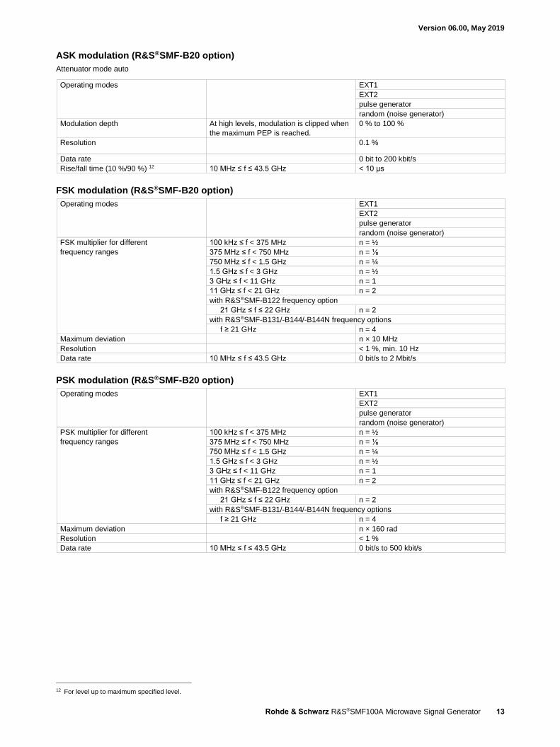
ASK modulation (R&S®SMF-B20 option)
Attenuator mode auto
Operating modes EXT1
EXT2
pulse generator
random (noise generator)
Modulation depth At high levels, modulation is clipped when
the maximum PEP is reached.
0 % to 100 %
Resolution 0.1 %
Data rate 0 bit to 200 kbit/s
Rise/fall time (10 %/90 %) 12 10 MHz ≤ f ≤ 43.5 GHz < 10 μs
FSK modulation (R&S®SMF-B20 option)
Operating modes EXT1
EXT2
pulse generator
random (noise generator)
FSK multiplier for different
frequency ranges
100 kHz ≤ f < 375 MHz n = ½
375 MHz ≤ f < 750 MHz n = ⅛
750 MHz ≤ f < 1.5 GHz n = ¼
1.5 GHz ≤ f < 3 GHz n = ½
3 GHz ≤ f < 11 GHz n = 1
11 GHz ≤ f < 21 GHz n = 2
with R&S®SMF-B122 frequency option
21 GHz ≤ f ≤ 22 GHz n = 2
with R&S®SMF-B131/-B144/-B144N frequency options
f ≥ 21 GHz n = 4
Maximum deviation n × 10 MHz
Resolution < 1 %, min. 10 Hz
Data rate 10 MHz ≤ f ≤ 43.5 GHz 0 bit/s to 2 Mbit/s
PSK modulation (R&S®SMF-B20 option)
Operating modes EXT1
EXT2
pulse generator
random (noise generator)
PSK multiplier for different
frequency ranges
100 kHz ≤ f < 375 MHz n = ½
375 MHz ≤ f < 750 MHz n = ⅛
750 MHz ≤ f < 1.5 GHz n = ¼
1.5 GHz ≤ f < 3 GHz n = ½
3 GHz ≤ f < 11 GHz n = 1
11 GHz ≤ f < 21 GHz n = 2
with R&S®SMF-B122 frequency option
21 GHz ≤ f ≤ 22 GHz n = 2
with R&S®SMF-B131/-B144/-B144N frequency options
f ≥ 21 GHz n = 4
Maximum deviation n × 160 rad
Resolution < 1 %
Data rate 10 MHz ≤ f ≤ 43.5 GHz 0 bit/s to 500 kbit/s
12 For level up to maximum specified level.

Version 06.00, May 2019
14 Rohde & Schwarz R&S®SMF100A Microwave Signal Generator
Narrow pulse modulation (R&S®SMF-K3 option)
Operating modes external, internal with R&S®SMF-K23
option
On/off ratio > 80 dB
Rise/fall time 10 %/90 % of RF amplitude
10 MHz ≤ f < 1 GHz < 20 ns
1 GHz ≤ f ≤ 43.5 GHz < 10 ns
Pulse repetition frequency 0 Hz to 10 MHz
Minimum pulse width with ALC state on
10 MHz ≤ f < 1 GHz 50 ns
f ≥ 1 GHz 500 ns 13
with ALC state off with R&S®SMF-B122, R&S®SMF-B131, R&S®SMF-B144 options
10 MHz ≤ f < 1 GHz 50 ns
f ≥ 1 GHz 20 ns
with ALC state off with R&S®SMF-B144N option
10 MHz ≤ f < 1 GHz 50 ns
1 GHz ≤ f ≤ 21 GHz 20 ns
f > 21 GHz 30 ns
Pulse overshoot typ. < 10 %
RF delay video output pulse to RF pulse typ. 35 ns
Video crosstalk 10 MHz ≤ f < 1 GHz < 150 mV (peak-to-peak)
1 GHz ≤ f < 3 GHz
without R&S®SMF-B32/-B34 options < 75 mV (peak-to-peak)
with R&S®SMF-B32/-B34 options < 150 mV (peak-to-peak)
3 GHz ≤ f ≤ 43.5 GHz
without R&S®SMF-B32/-B34 options < 5 mV (peak-to-peak)
with R&S®SMF-B32/-B34 options < 10 mV (peak-to-peak)
Chirped pulses (R&S®SMF-B20 option, in combination with the R&S®SMF-K3 and R&S®SMF-K23
options)
Chirp bandwidth multiplier for different
frequency ranges
100 kHz ≤ f < 375 MHz n = ½
375 MHz ≤ f < 750 MHz n = ⅛
750 MHz ≤ f < 1.5 GHz n = ¼
1.5 GHz ≤ f < 3 GHz n = ½
3 GHz ≤ f < 11 GHz n = 1
11 GHz ≤ f < 21 GHz n = 2
with R&S®SMF-B122 frequency option
21 GHz ≤ f ≤ 22 GHz n = 2
with R&S®SMF-B131/-B144/-B144N frequency options
f ≥ 21 GHz n = 4
Operating modes auto, external trigger, external gate
Chirp direction up, down
Maximum bandwidth n × 20 MHz
Pulse period ≥ 200 ns
Pulse width ≥ 100 ns
Maximum chirp rate n × 10 MHz/µs, nominal
13 With attenuator (R&S®SMF-B26/-B27 option), attenuator mode auto. Without attenuator (R&S®SMF-B26/-B27 option), level ≥ 0 dBm.

Version 06.00, May 2019
Rohde & Schwarz R&S®SMF100A Microwave Signal Generator 15
Inputs for external modulation signals
Modulation inputs EXT1 and EXT2
for FM,M, AM, LOG AM, FSK, PSK and
ASK
input voltage for FM,M and AM
(peak value for selected modulation depth
or deviation)
1 V
input voltage range for LOG AM –6 V to +6 V
input level for FSK, PSK and ASK TTL-compatible signal
input impedance 50 Ω, 600 Ω or 100 kΩ
polarity for FSK, PSK and ASK selectable
modulation input bandwidth for
FM, M, AM and LOG AM
200 kHz or 10 MHz
Modulation input PULSE IN input level threshold TTL, +0.5 V or –2.5 V
input impedance 50 Ω or 10 kΩ
polarity selectable
Modulation sources
Internal modulation generators (LF generator 1, LF generator 2, noise generator)
(R&S®SMF-B20 option)
Waveforms LF generator 1, LF generator 2 sine, pulse, triangle, user-programmable
trapezoid ∆T = 20 ns
noise generator noise amplitude distribution:
Gaussian, equal
Sine frequency range 0.1 Hz to 10 MHz
frequency uncertainty < 0.003 Hz
+ relative deviation of reference frequency
resolution of setting 0.1 Hz
setting time to within < 1 × 10⁻⁷,
after IEC/IEEE bus delimiter
< 3 ms
distortion at f < 100 kHz, RL > 50 Ω,
level (Vp) 0.5 V
< 0.5 %
Pulse period 1 µs to 100 s
width 1 µs to 100 s
resolution of setting 20 µs
Triangle period 1 µs to 100 s
rise time 1 µs to 100 s
resolution of setting 20 ns
Trapezoid period 1 µs to 100 s
rise time 1 µs to 100 s
high time 1 µs to 100 s
fall time 1 µs to 100 s
resolution of setting 20 ns
Noise generator noise amplitude distribution Gaussian, equal
noise bandwidth 100 kHz to 10 MHz
Frequency response f ≤ 500 kHz < 0.5 dB
f ≤ 10 MHz < 3 dB
Output voltage Vp at LF connector, open circuit voltage 1 mV to 6 V
EMF resolution 1 mV
EMF setting accuracy at 1 kHz,
level (Vp) 1 V
< 11 mV
Output impedance 50 Ω
Sweep digital sweep in discrete steps
operating modes automatic, step, single sweep,
external single, external step,
external start/stop,
manual or external trigger,
linear or logarithmic spacing
sweep range full frequency range
step width (lin) full frequency range
step width (log) 0.01 % to 100 % per step

Version 06.00, May 2019
16 Rohde & Schwarz R&S®SMF100A Microwave Signal Generator
Pulse generator (R&S®SMF-K23 option)
Operating modes automatic, external trigger, external gate,
single pulse, double pulse, delayed pulse
(external trigger)
Active trigger edge positive or negative
Pulse period 20 ns to 100 s
Resolution 5 ns
Uncertainty relative deviation of reference frequency
Pulse width Pulse width of double pulses can be set
independently.
5 ns to 100 s
Resolution 5 ns
Uncertainty Pulse width of double pulses can be set
independently.
relative deviation of reference frequency
Pulse delay 10 ns to 100 s
Resolution 5 ns
Uncertainty relative deviation of reference frequency
Double-pulse delay 10 ns to 100 s
Resolution 5 ns
Uncertainty relative deviation of reference frequency
External trigger
Delay external input pulse to SYNC output pulse typ. 55 ns
Jitter < 5 ns
Generator output pulse out LVC signal (RL ≥ 50 Ω)
Pulse train (R&S®SMF-K27 option)
Option R&S®SMF-K27 extends the functionality of the high performance pulse generator (R&S®SMF-K23 option). With this option
pulses and sequences of pulses can be defined freely, in order to generate jittered or staggered pulse scenarios widely used in radar
applications.
Pulse mode freely settable pulse width, pulse spacing
and pulse sequences
train
Trigger mode continuous trigger with internal trigger
source
auto
external triggered
Number of bursts 1 to 2047
Number of identical pulses per burst 1 to 65535
Pulse on time range 0 s to 5 ms
Pulse off time range 5 ns to 5 ms
Pulse on and off time resolution 5 ns

Version 06.00, May 2019
Rohde & Schwarz R&S®SMF100A Microwave Signal Generator 17
R&S®NRP-Zxx power analysis (option R&S®SMF-K28)
Modes sweep power versus frequency frequency
sweep power versus power power
sweep power versus time (trace function) time
General settings
Number of points per sweep (steps) 10 to 1000
Frequency range depending on R&S®NRP-Z power sensor
and R&S®SMF100A frequency option
support of frequency converting DUTs
Y-axis setting range –100 dBm to +100 dBm
Uncertainty of measured power determined by used power sensor
Sweep mode single
continuous
Display modes block diagram still visible, markers not
visible
small
maximum size with markers full screen marker
maximum size, markers not visible full screen
Number of traces used for sensor data or as reference trace 3
Number of markers 4
Trace data export supported file formats jpg, bmp, xpm, png, csv
Resolution of saved graphic 320 × 240 pixel, 640 × 480 pixel,
800 × 600 pixel or 1024 × 768 pixel
Mode frequency (sweep power versus frequency)
Spacing linear, logarithmic
Timing mode aperture time and averaging depends on
power sensor and timing mode
see table below for details
fast, normal
Sweep time set automatically depends on timing mode, steps and power
sensor
e.g. R&S®NRP-Z21,
timing mode fast, 200 steps
approx. 2.5 s
Mode power (sweep power versus power)
Spacing dB steps linear
Timing mode Aperture time and averaging depends on
power sensor and timing mode, see table
below for details.
fast, normal
Sweep time set automatically depends on timing mode, steps and power
sensor
e.g. R&S®NRP-Z21,
timing mode fast, 200 steps
approx. 2.5 s
Mode time (sweep power versus time)
Spacing linear
Sweep time R&S®NRP-Z11, -Z21, -Z22, -Z23, -Z24, -Z28, -Z31
setting range 100 µs to 300 ms
resolution 10 µs
R&S®NRP-Z81, -Z85
setting range 100 ns to 1 s
Resolution,
(sweep time/steps ) ≥ 12.5 ns
12.5 ns
Resolution,
(sweep time/steps ) < 12.5 ns,
periodic signals,
trigger mode internal triggered
2 ns
Trace offset positive, negative
Average 1 to 1024
Trigger modes internal triggered auto
external triggered, R&S®NRP-Z3 required external
Trigger level setting range full level range
Trigger hysteresis setting range 0 dB to 10 dB
Trigger drop out time setting range 0 s to 10 s
Version 06.00, May 2019
18 Rohde & Schwarz R&S®SMF100A Microwave Signal Generator
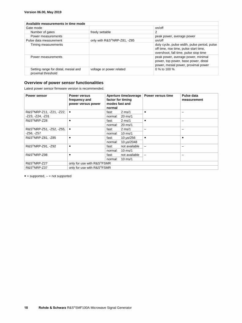
Available measurements in time mode
Gate mode on/off
Number of gates freely settable 2
Power measurements peak power, average power
Pulse data measurement only with R&S®NRP-Z81, -Z85 on/off
Timing measurements duty cycle, pulse width, pulse period, pulse
off time, rise time, pulse start time,
overshoot, fall time, pulse stop time
Power measurements peak power, average power, minimal
power, top power, base power, distal
power, mesial power, proximal power
Setting range for distal, mesial and
proximal threshold
voltage or power related 0 % to 100 %
Overview of power sensor functionalities
Latest power sensor firmware version is recommended.
Power sensor Power versus
frequency and
power versus power
Aperture time/average
factor for timing
modes fast and
normal
Power versus time Pulse data
measurement
R&S®NRP-Z11, -Z21, -Z22,
-Z23, -Z24, -Z31
fast: 2 ms/1 –
normal: 20 ms/1
R&S®NRP-Z28 fast: 2 ms/1 –
normal: 20 ms/1
R&S®NRP-Z51, -Z52, -Z55,
-Z56, -Z57
fast: 2 ms/1 – –
normal: 10 ms/1
R&S®NRP-Z81, -Z85 fast: 10 µs/256
normal: 10 µs/2048
R&S®NRP-Z91, -Z92 fast: not available – –
normal: 10 ms/1
R&S®NRP-Z98 fast: not available – –
normal: 10 ms/1
R&S®NRP-Z27 only for use with R&S®FSMR
R&S®NRP-Z37 only for use with R&S®FSMR
= supported, – = not supported

Version 06.00, May 2019
Rohde & Schwarz R&S®SMF100A Microwave Signal Generator 19
General data
Remote control
Parameter Description/condition Value
Interfaces with R&S®SMF-B83 option IEC 60625 (GPIB IEEE-488.2)
Ethernet/LAN (10/100BASE-T)
USB 2.0 (high speed)
serial (RS-232) 14
Command set SCPI 1999.5 or compatible command
sets
Compatible command sets These command sets can be selected in
order to emulate another instrument.
Agilent/HP 4028
Agilent/HP 8340A/B
Agilent/HP 8341A/B
Agilent/HP 83620A/B
Agilent/HP 83630A/B
Anritsu/Wiltron 68037B
Anritsu/Wiltron 68045B
Anritsu/Wiltron 68047B
Racal 3102
full list can be found on the web
IEC/IEEE bus address 0 to 30
Ethernet/LAN protocols and services VISA VXI-11 (remote control)
Telnet/RawEthernet (remote control)
VNC (remote operation with web
browser)
FTP (file transfer protocol)
SMB (mapping parts of the instrument to
a host file system)
Ethernet/LAN addressing DHCP, static,
support of ZeroConf and M-DNS to ease
the direct connection to a system
controller
USB protocol VISA USB-TMC
14 USB serial adapter required, R&S®TS-USB1 recommended.

Version 06.00, May 2019
20 Rohde & Schwarz R&S®SMF100A Microwave Signal Generator
Operating data
Power supply input voltage range
50 Hz to 60 Hz, –5 %/+10 % 100 V to 240 V (AC) ± 10 %
50 Hz to 400 Hz, –5 %/+10 % 100 V to 120 V (AC) ± 10 %
power consumption 250 VA
Power factor correction in line with EN 61000-3-2
Electromagnetic compatibility EU: in line with EMC Directive
2004/108/EC
applied harmonized standards:
EN 61326-1 (industrial environment),
EN 61326-2-1,
EN 55011 (class A),
EN 61000-3-2,
EN 61000-3-3
Immunity to interfering field strength up to 10 V/m
Environmental conditions operating temperature range 0 °C to +55 °C,
in line with EN 60068-2-1, EN 60068-2-2
maximum operating altitude 4600 m
storage temperature range –40 °C to +75 °C
climatic resistance,
+40 °C/95 % rel. humidity
in line with EN 60068-2-3
Mechanical resistance vibration, sinusoidal 5 Hz to 150 Hz,
max. 2 g at 55 Hz,
max. 0.5 g at 55 Hz to 150 Hz,
in line with EN 60068-2-6
vibration, random 10 Hz to 300 Hz, acceleration 1.2 g (RMS),
in line with EN 60068-2-64
shock 40 g shock spectrum,
in line with EN 60068-2-27,
MIL-STD-810E
Electrical safety in line with IEC 61010-1, EN 61010-1,
CAN/CSA-C22.2 No. 61010-1-04,
UL 61010-1
Approvals VDE-GS, CCSAUS
Dimensions W × H × D 427 mm × 132 mm × 550 mm
(16.81 in × 5.2 in × 21.65 in)
Weight when fully equipped 18 kg (39.68 lb)
Recommended calibration interval 3 years

Version 06.00, May 2019
Rohde & Schwarz R&S®SMF100A Microwave Signal Generator 21
Ordering information Designation Type Order No.
Microwave signal generator 15 R&S®SMF100A 1167.0000.02
Including power cable, quick start guide, and CD-ROM (with operating and service manual)
Options
Frequency range, 1 GHz to 22 GHz 16
(Adapter 3.5 mm female included)
R&S®SMF-B122 1167.7004.03
Frequency range, 1 GHz to 31.8 GHz 16
(Adapter 2.9 mm female included)
R&S®SMF-B131 1167.7140.02
Frequency range, 1 GHz to 43.5 GHz 16
(Adapter 2.4 mm female + 2.9 mm female included)
R&S®SMF-B144 1167.7204.03
Frequency range, 1 GHz to 43.5 GHz,
minimum pulse width limited 16
(Adapter 2.4 mm female + 2.9 mm female included)
R&S®SMF-B144N 1167.7240.02
OCXO reference oscillator 17, 18 R&S®SMF-B1 1167.9159.02
Frequency extension, 100 kHz to 1 GHz 17 R&S®SMF-B2 1167.4005.02
AM/FM/φM/LOG AM modulator 17 R&S®SMF-B20 1167.9594.02
Enhanced phase noise performance 17 R&S®SMF-B22 1415.2204.02
Step attenuator, 100 kHz to 22 GHz 17 R&S®SMF-B26 1167.5553.02
Step attenuator, 100 kHz to 43.5 GHz 17 R&S®SMF-B27 1167.5776.02
High output power (not in combination with R&S®SMF-B2) 17 R&S®SMF-B32 1415.2304.02
High output power (in combination with R&S®SMF-B2) 17 R&S®SMF-B34 1415.2404.02
Rear connectors 22 GHz 17 R&S®SMF-B81 1167.5999.02
Rear connectors 43.5 GHz 17 R&S®SMF-B82 1167.6208.02
Removable GPIB 19 R&S®SMF-B83 1167.6408.02
Removable USB 19 R&S®SMF-B84 1167.6608.02
Removable flash disk 17, 19 R&S®SMF-B85 1167.6808.02
Narrow pulse modulation R&S®SMF-K3 1167.7804.02
Ramp sweep R&S®SMF-K4 1167.7604.02
Pulse generator R&S®SMF-K23 1167.7704.02
Pulse train 20 R&S®SMF-K27 1415.2004.02
Power analysis R&S®SMF-K28 1415.2104.02
Documentation of calibration values R&S®DCV-2 0240.2193.19
DKD (ISO 17025) calibration including ISO 9000 calibration
(can only be ordered with the device)
R&S®SMF22-DKD 1161.3594.00
R&S®SMF44-DKD 1161.3620.00
Recommended extras
Wideband power sensor (for use with R&S®SMF-K28) R&S®NRP-Z81 1137.9009.02
Hardcopy manuals (in English, UK) 1167.2319.32
Hardcopy manuals (in English, US) 1167.2319.39
Spare compact flash card (R&S®SMF-B85 required) R&S®SMF-Z10 1167.8100.02
19“ rack adapter R&S®ZZA-311 1096.3277.00
Keyboard with USB interface (US character set) R&S®PSL-Z2 1157.6870.04
Mouse with USB interface, optical R&S®PSL-Z10 1157.7060.03
USB adapter for R&S®NRP-Zxx power sensors R&S®NRP-Z4 1146.8001.02
USB serial adapter for RS-232 remote control R&S®TS-USB1 6124.2531.00
External USB DVD drive R&S®PSP-B6 1134.8201.22
Adapters for R&S®SMF100A with R&S®SMF-B122 frequency option
3.5 mm female 1021.0512.00
3.5 mm male 1021.0529.00
N female 1021.0535.00
N male 1021.0541.00
Adapters for R&S®SMF100A with R&S®SMF-B131/-B144/-B144N frequency options
2.4 mm female 1088.1627.02
2.9 mm female 1036.4790.00
2.9 mm male 1036.4802.00
N female 1036.4777.00
N male 1036.4783.00
15 The base unit can only be ordered together with R&S®SMF-B122 or R&S®SMF-B144 frequency option. 16 Option fitted by factory. 17 Option fitted by factory or especially equipped by Rohde & Schwarz service department. 18 Option cannot be installed with R&S®SMF-B22 enhanced phase noise performance option (then not required). 19 Only two of the three options R&S®SMF-B83, R&S®SMF-B84, R&S®SMF-B85 can be installed simultaneously. 20 R&S®SMF-K23 pulse generator option required.

Version 06.00, May 2019
22 Rohde & Schwarz R&S®SMF100A Microwave Signal Generator
Service options
Extended warranty, one year R&S®WE1 Please contact your local
Rohde & Schwarz sales office. Extended warranty, two years R&S®WE2
Extended warranty, three years R&S®WE3
Extended warranty, four years R&S®WE4
Extended warranty with calibration coverage, one year R&S®CW1
Extended warranty with calibration coverage, two years R&S®CW2
Extended warranty with calibration coverage, three years R&S®CW3
Extended warranty with calibration coverage, four years R&S®CW4
Extended warranty with a term of one to four years (WE1 to WE4)
Repairs carried out during the contract term are free of charge 21. Necessary calibration and adjustments carried out during repairs are
also covered. Simply contact the forwarding agent we name; your product will be picked up free of charge and returned to you in top
condition a couple of days later.
Extended warranty with calibration (CW1 to CW4)
Enhance your extended warranty by adding calibration coverage at a package price. This package ensures that your
Rohde & Schwarz product is regularly calibrated, inspected and maintained during the term of the contract. It includes all repairs 21 and
calibration at the recommended intervals as well as any calibration carried out during repairs or option upgrades.
21 Excluding defects caused by incorrect operation or handling and force majeure. Wear-and-tear parts are not included.

Version 06.00, May 2019
Rohde & Schwarz R&S®SMF100A Microwave Signal Generator 23

R&S® is a registered trademark of Rohde & Schwarz GmbH & Co. KG
Trade names are trademarks of the owners
PD 5213.7660.22 | Version 06.00 | May 2019 (jr)
R&S®SMF100A Microwave Signal Generator
Data without tolerance limits is not binding | Subject to change
© 2007 - 2019 Rohde & Schwarz GmbH & Co. KG | 81671 Munich, Germany
Service that adds value Worldwide Local and personalized Customized and flexible Uncompromising quality Long-term dependability
5213
.766
0.22
06.
00 P
DP
1 e
n
Sustainable product design Environmental compatibility and eco-footprint Energy efficiency and low emissions Longevity and optimized total cost of ownership
Certified Environmental Management
ISO 14001Certified Quality Management
ISO 9001
Regional contact Europe, Africa, Middle East | +49 89 4129 12345 [email protected]
North America | 1 888 TEST RSA (1 888 837 87 72) [email protected]
Latin America | +1 410 910 79 88 [email protected]
Asia Pacific | +65 65 13 04 88 [email protected]
China | +86 800 810 82 28 | +86 400 650 58 96 [email protected]
Rohde & SchwarzThe Rohde & Schwarz electronics group offers innovative solutions in the following business fields: test and mea-surement, broadcast and media, secure communications, cybersecurity, monitoring and network testing. Founded more than 80 years ago, the independent company which is headquartered in Munich, Germany, has an extensive sales and service network with locations in more than 70 countries.
www.rohde-schwarz.com
Rohde & Schwarz trainingwww.training.rohde-schwarz.com
5213766022
SMF100A_dat-sw_en_5213-7660-22_v0600_cover.indd 2 23.05.2019 16:02:36