rapid development using blackfin
TRANSCRIPT
The World Leader in High Performance Signal Processing Solutions
Rapid Development of a Blackfin-based Video Application
Presented By: Glen Ouellette
2
About this Module
This module discusses the rapid development process of a Blackfin® Video application using readily available and fully supported software and hardware modules.
It is recommended that users have some understanding of:!Basic knowledge of software terminology!Experience in embedded systems !Blackfin System Services and Device Drivers
3
Module Outline
!Video-In" Refresher on Device Driver" Video Capture using ADV7183B Video Decoder
!Video-Out" Video Display using ADV7179 Video Encoder
!Video Compression" Overview of MJPEG offering" Encoding Video Data
!USB " Blackfin USB-LAN EZ-Extender" Blackfin-Host data transfer over USB 2.0
!Rapid Develeopment of a MJPEG Encode

4
Outline of Video-In Sub-module
!A short Device Driver refresher
!Simple Video Capture using ADV7183B Video Decoder

5
Device Driver Refresher
!Standardized API " User interface is the same across all device drivers
!Independent of driver" Allows buffers to be passed from driver to driver
!Independent of processor" Does not require change when moving from BF561 to BF537
!Device Drivers are Totally Independent !User Application provides buffers to device driver
" Provided to driver via adi_dev_Read() or adi_dev_Write()!Inbound buffers – Filled with data received from the device!Outbound buffers – Contain data to send out through the device
6
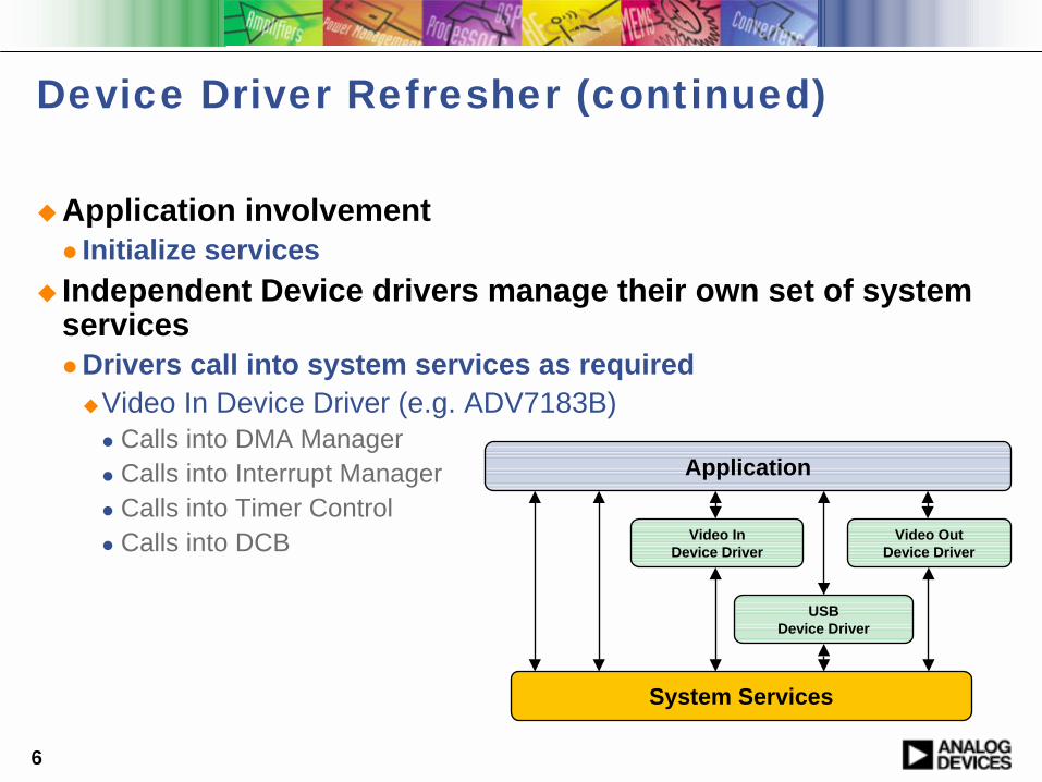
!Application involvement" Initialize services
! Independent Device drivers manage their own set of system services" Drivers call into system services as required
!Video In Device Driver (e.g. ADV7183B)" Calls into DMA Manager" Calls into Interrupt Manager " Calls into Timer Control" Calls into DCB
Application
Video InDevice Driver
USBDevice Driver
Video OutDevice Driver
System Services
Device Driver Refresher (continued)

7
Additional Information on Device Drivers
!Device Drivers and System Services Manual for Blackfin Processors
−http://www.analog.com/processors/manuals
!Device Drivers and System Services Addendum (Sept 2005)− ftp://ftp.analog.com/pub/tools/patches/Blackfin/VDSP++4.0/
8
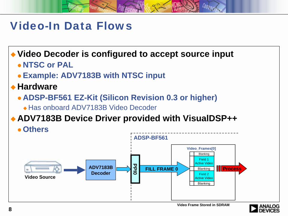
Video-In Data Flows
!Video Decoder is configured to accept source input" NTSC or PAL" Example: ADV7183B with NTSC input
!Hardware" ADSP-BF561 EZ-Kit (Silicon Revision 0.3 or higher)
!Has onboard ADV7183B Video Decoder!ADV7183B Device Driver provided with VisualDSP++
" Others
Blanking
Field 1Active Video
Blanking
Blanking
Field 2Active Video
Video_Frames[0]
FILL FRAME 0
PPI0ADV7183BDecoder
Process
Video Frame Stored in SDRAM
ADSP-BF561
Video Source
9
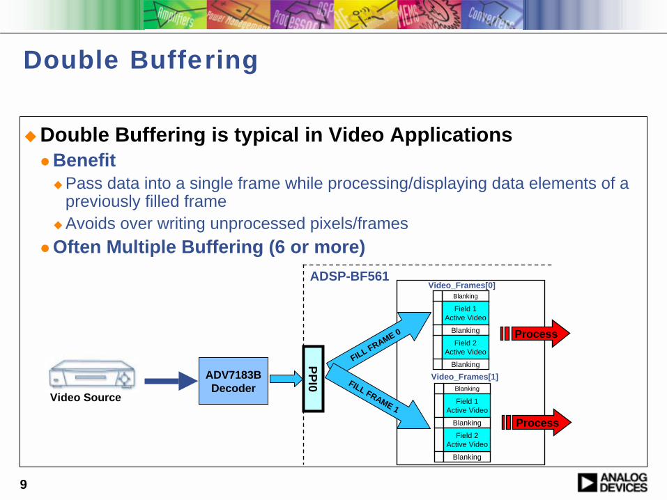
Double Buffering
!Double Buffering is typical in Video Applications" Benefit
!Pass data into a single frame while processing/displaying data elements of a previously filled frame
!Avoids over writing unprocessed pixels/frames" Often Multiple Buffering (6 or more)
Video_Frames[0]
Video_Frames[1]
FILL FRAME 0
FILL FRAME 1
ADSP-BF561
PPI0ADV7183BDecoder Blanking
Field 1Active Video
Blanking
Blanking
Field 2Active Video
Blanking
Field 1Active Video
Blanking
Blanking
Field 2Active Video
Process
Process
Video Source

10
Dataflow Method: Chaining with Loopback
!Chaining with Loopback" Device driver automatically loops back to the first buffer after the
last buffer in the chain is processed" Application doesn’t need to resupply buffers
!Lower overhead!Device driver never “starves” for data
Video_Frames[0] Video_Frames[1]
Video_Frames[0]
Video_Frames[1]
FILL FRAME 0
FILL FRAME 1
ADSP-BF561
PP
I0ADV7183BDecoder Blanking
Field 1Active Video
Blanking
Blanking
Field 2Active Video
Blanking
Field 1Active Video
Blanking
Blanking
Field 2Active Video

11
Video-In Programming Sequence
! Initialize System Services!Good practice to reset Video Decoder
" On Blackfin EZ-Kits, ADV7183B Reset is controlled via Programmable Flag
!Open ADV7183B Device Driver" ‘AD7183DriverHandle’" Configure for Inbound traffic from ADV7183B to Video Buffer" PPI_Callback_In
ezErrorCheck(adi_dev_Open(DeviceManagerHandle, &ADIAD7183EntryPoint, // pdd entry point0, // device instanceNULL, // client handle callback identifier&AD7183DriverHandle, // DevMgr handle for this deviceADI_DEV_DIRECTION_INBOUND,// data direction for this deviceDMAManagerHandle, // handle to DmaMgr for this deviceDCBManagerHandle, // handle to deferred callback servicePPI_Callback_In)); // deferred callback
/********* open AD7183 via PPI0 ****************************************/ezErrorCheck(adi_dev_Control(AD7183DriverHandle, ADI_AD7183_CMD_OPEN_PPI, (void *)0));
12
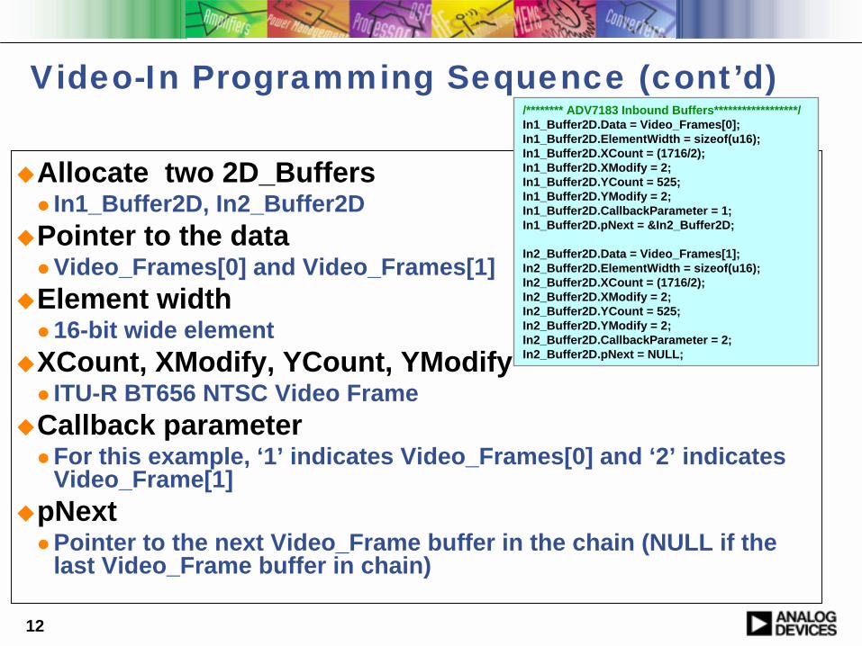
!Allocate two 2D_Buffers " In1_Buffer2D, In2_Buffer2D
!Pointer to the data" Video_Frames[0] and Video_Frames[1]
!Element width" 16-bit wide element
!XCount, XModify, YCount, YModify" ITU-R BT656 NTSC Video Frame
!Callback parameter" For this example, ‘1’ indicates Video_Frames[0] and ‘2’ indicates
Video_Frame[1]!pNext
" Pointer to the next Video_Frame buffer in the chain (NULL if thelast Video_Frame buffer in chain)
/******** ADV7183 Inbound Buffers******************/In1_Buffer2D.Data = Video_Frames[0];In1_Buffer2D.ElementWidth = sizeof(u16);In1_Buffer2D.XCount = (1716/2);In1_Buffer2D.XModify = 2;In1_Buffer2D.YCount = 525;In1_Buffer2D.YModify = 2;In1_Buffer2D.CallbackParameter = 1;In1_Buffer2D.pNext = &In2_Buffer2D;
In2_Buffer2D.Data = Video_Frames[1];In2_Buffer2D.ElementWidth = sizeof(u16);In2_Buffer2D.XCount = (1716/2);In2_Buffer2D.XModify = 2;In2_Buffer2D.YCount = 525;In2_Buffer2D.YModify = 2;In2_Buffer2D.CallbackParameter = 2;In2_Buffer2D.pNext = NULL;
Video-In Programming Sequence (cont’d)

13
Then Enable Dataflow Sequence
! Start Capturing Video Data from PPI0 into Video_Frames[0] and Video_Frame[1] " adi_dev_Control(AD7183DriverHandle, ADI_DEV_CMD_SET_DATAFLOW, (void*)TRUE));
Video_Frames[0]
Video_Frames[1]
FILL FRAME 0
FILL FRAME 1P
PI0
ADSP-BF561
ADV7183BDecoder
Blanking
Field 1Active Video
Blanking
Blanking
Field 2Active Video
Blanking
Field 1Active Video
Blanking
Blanking
Field 2Active Video

14
Programming Sequence for ADV7183BA
pplic
atio
n
Open ADV7183 driver for Inbound dataflow
Configure ADV7183 driver for chained loopback, ITU-R BT656 mode etc.
Enable dataflow
Driver makes callback when frame buffer is filled
Callback function provides next buffer for driver to fill
AD
V718
3B D
river
Provide 2 frame buffers for driver to fill
15
Outline for Video-Out Sub-module
!Simple Video Display using ADV7179 Video Encoder
16
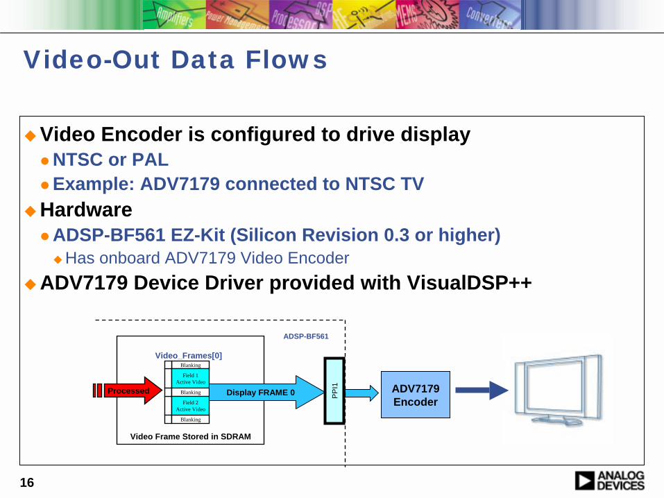
Video-Out Data Flows
!Video Encoder is configured to drive display" NTSC or PAL" Example: ADV7179 connected to NTSC TV
!Hardware" ADSP-BF561 EZ-Kit (Silicon Revision 0.3 or higher)
!Has onboard ADV7179 Video Encoder!ADV7179 Device Driver provided with VisualDSP++
Blanking
Field 1Active Video
Blanking
Blanking
Field 2Active Video
Video_Frames[0]
Display FRAME 0 PP
I1Processed
Video Frame Stored in SDRAM
ADSP-BF561
ADV7179Encoder
17
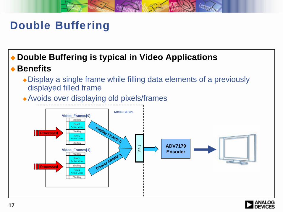
Double Buffering
!Double Buffering is typical in Video Applications!Benefits
!Display a single frame while filling data elements of a previously displayed filled frame
!Avoids over displaying old pixels/frames
Blanking
Field 1Active Video
Blanking
Blanking
Field 2Active Video
Blanking
Field 1Active Video
Blanking
Blanking
Field 2Active Video
Video_Frames[0]
Video_Frames[1]
Display FRAME 1
Display FRAME 0P
PI1
ADSP-BF561
Processed
Processed
ADV7179Encoder
18
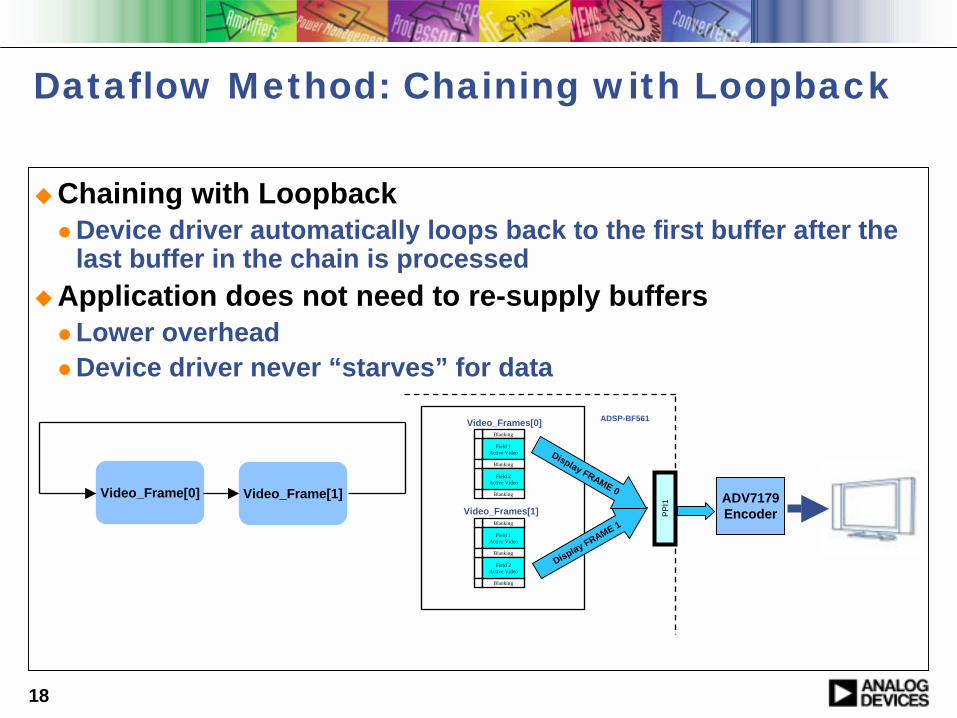
Dataflow Method: Chaining with Loopback
!Chaining with Loopback" Device driver automatically loops back to the first buffer after the
last buffer in the chain is processed!Application does not need to re-supply buffers
" Lower overhead" Device driver never “starves” for data
Video_Frame[0] Video_Frame[1]
Blanking
Field 1Active Video
Blanking
Blanking
Field 2Active Video
Blanking
Field 1Active Video
Blanking
Blanking
Field 2Active Video
Video_Frames[0]
Video_Frames[1]
Display FRAME 1
Display FRAME 0
PPI
1
ADSP-BF561
ADV7179Encoder
19
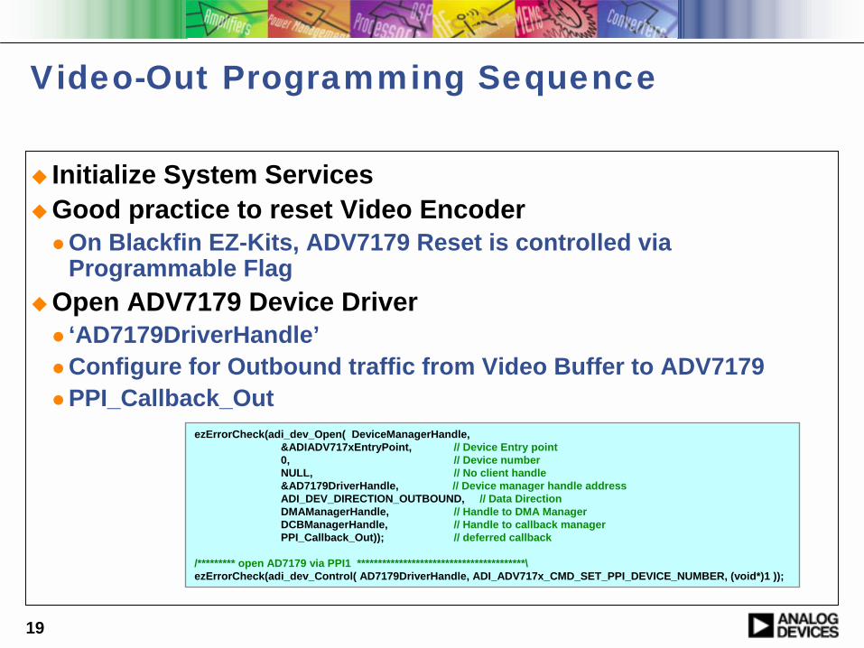
Video-Out Programming Sequence
! Initialize System Services!Good practice to reset Video Encoder
" On Blackfin EZ-Kits, ADV7179 Reset is controlled via Programmable Flag
!Open ADV7179 Device Driver" ‘AD7179DriverHandle’" Configure for Outbound traffic from Video Buffer to ADV7179" PPI_Callback_Out
ezErrorCheck(adi_dev_Open( DeviceManagerHandle, &ADIADV717xEntryPoint, // Device Entry point0, // Device numberNULL, // No client handle&AD7179DriverHandle, // Device manager handle addressADI_DEV_DIRECTION_OUTBOUND, // Data DirectionDMAManagerHandle, // Handle to DMA ManagerDCBManagerHandle, // Handle to callback managerPPI_Callback_Out)); // deferred callback
/********* open AD7179 via PPI1 ****************************************\ezErrorCheck(adi_dev_Control( AD7179DriverHandle, ADI_ADV717x_CMD_SET_PPI_DEVICE_NUMBER, (void*)1 ));
20
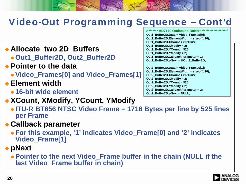
!Allocate two 2D_Buffers " Out1_Buffer2D, Out2_Buffer2D
!Pointer to the data" Video_Frames[0] and Video_Frames[1]
!Element width" 16-bit wide element
!XCount, XModify, YCount, YModify" ITU-R BT656 NTSC Video Frame = 1716 Bytes per line by 525 lines
per Frame!Callback parameter
" For this example, ‘1’ indicates Video_Frame[0] and ‘2’ indicatesVideo_Frame[1]
!pNext" Pointer to the next Video_Frame buffer in the chain (NULL if the
last Video_Frame buffer in chain)
Video-Out Programming Sequence – Cont’d/******** AD7179 Outbound Buffers*******************/Out1_Buffer2D.Data = Video_Frames[0];Out1_Buffer2D.ElementWidth = sizeof(u16);Out1_Buffer2D.XCount = (1716/2);Out1_Buffer2D.XModify = 2;Out1_Buffer2D.YCount = 525;Out1_Buffer2D.YModify = 2;Out1_Buffer2D.CallbackParameter = 1; Out1_Buffer2D.pNext = &Out2_Buffer2D;
Out2_Buffer2D.Data = Video_Frames[1];Out2_Buffer2D.ElementWidth = sizeof(u16);Out2_Buffer2D.XCount = (1716/2);Out2_Buffer2D.XModify = 2;Out2_Buffer2D.YCount = 525;Out2_Buffer2D.YModify = 2;Out2_Buffer2D.CallbackParameter = 2;Out2_Buffer2D.pNext = NULL;
21
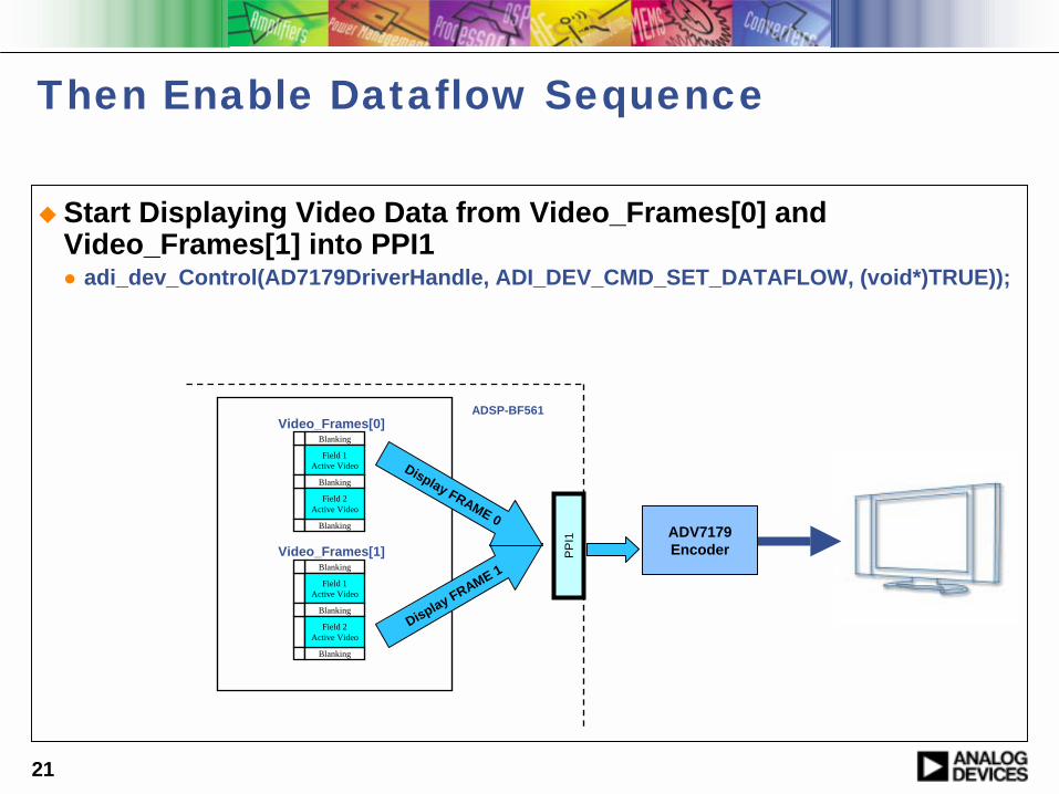
Then Enable Dataflow Sequence
! Start Displaying Video Data from Video_Frames[0] and Video_Frames[1] into PPI1" adi_dev_Control(AD7179DriverHandle, ADI_DEV_CMD_SET_DATAFLOW, (void*)TRUE));
Blanking
Field 1Active Video
Blanking
Blanking
Field 2Active Video
Blanking
Field 1Active Video
Blanking
Blanking
Field 2Active Video
Video_Frames[0]
Video_Frames[1]
Display FRAME 1
Display FRAME 0
PP
I1
ADSP-BF561
ADV7179Encoder

22
Programming Sequence for ADV7179A
pplic
atio
n
Open ADV7179 driver for Outbound dataflow
Configure ADV7179 driver for chained loopback, ITU-R BT656 mode etc.
Enable dataflow
Driver makes callback when frame buffer has been sent out
Callback function provides next buffer for driver to send out
AD
V717
9 D
riverProvide 2 frame buffers for driver to send out

23
Recap: Video-In and Video-Out
! Installed ADV7183B Device Driver" Video Decoder is configured to accept source input
! Installed ADV7179 Device Driver" Video Encoder is configured to drive display
! Independent Drivers, but can share Video Frame Buffers
Blanking
Field 1Active Video
Blanking
Blanking
Field 2Active Video
Blanking
Field 1Active Video
Blanking
Blanking
Field 2Active Video
Video_Frames[0]
Video_Frames[1]FILL FRAME 0
FILL FRAME 1
PPI0
ADV7183BDecoder
ADSP-BF561
Video Source
Blanking
Field 1Active Video
Blanking
Blanking
Field 2Active Video
Blanking
Field 1Active Video
Blanking
Blanking
Field 2Active Video
Video_Frames[0]
Video_Frames[1]
Display FRAME 1
Display FRAME 0
PPI
1
ADSP-BF561
ADV7179Encoder
24
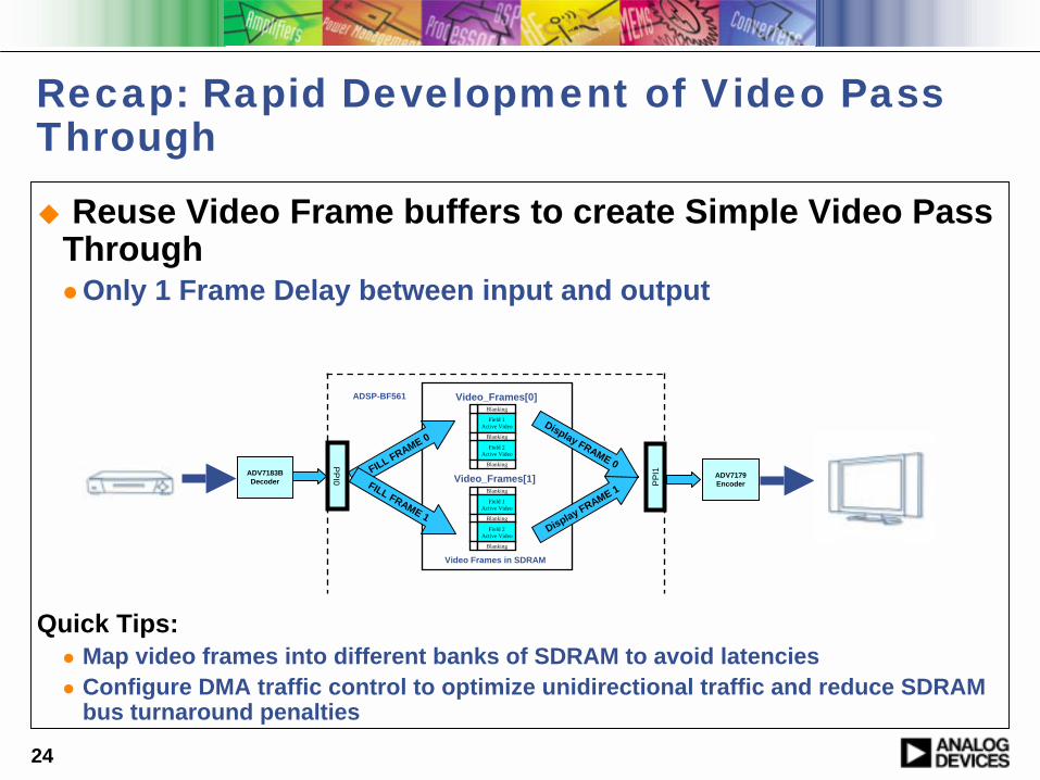
Recap: Rapid Development of Video Pass Through
! Reuse Video Frame buffers to create Simple Video Pass Through" Only 1 Frame Delay between input and output
Quick Tips:" Map video frames into different banks of SDRAM to avoid latencies" Configure DMA traffic control to optimize unidirectional traffic and reduce SDRAM
bus turnaround penalties
Blanking
Field 1Active Video
Blanking
Blanking
Field 2Active Video
Blanking
Field 1Active Video
Blanking
Blanking
Field 2Active Video
Video_Frames[0]
Video_Frames[1]FILL FRAME 0
FILL FRAME 1
PPI0ADV7183B
Decoder
ADSP-BF561
Display FRAME 1
Display FRAME 0
PPI
1
ADV7179Encoder
Video Frames in SDRAM
25
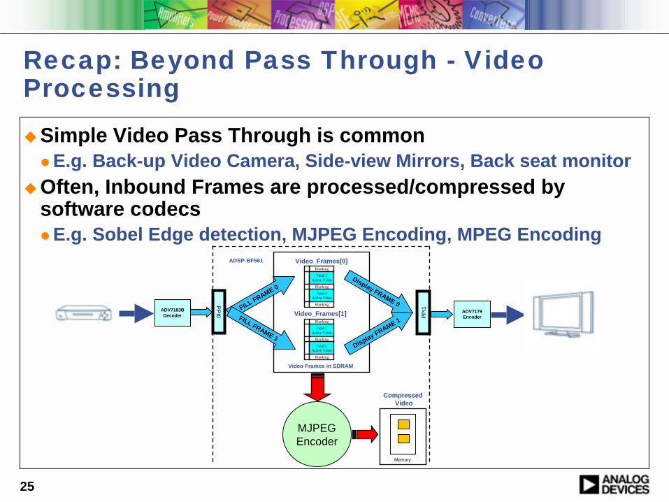
Recap: Beyond Pass Through - Video Processing !Simple Video Pass Through is common
" E.g. Back-up Video Camera, Side-view Mirrors, Back seat monitor!Often, Inbound Frames are processed/compressed by
software codecs" E.g. Sobel Edge detection, MJPEG Encoding, MPEG Encoding
Blanking
Field 1Active Video
Blanking
Blanking
Field 2Active Video
Blanking
Field 1Active Video
Blanking
Blanking
Field 2Active Video
Video_Frames[0]
Video_Frames[1]FILL FRAME 0
FILL FRAME 1
PPI0ADV7183B
Decoder
ADSP-BF561
Display FRAME 1
Display FRAME 0
PPI
1
ADV7179Encoder
Video Frames in SDRAM
MJPEGEncoder
Memory
Compressed Video
26
Outline for Encoding Video Data Sub-module!Overview of the MJPEG offering
!Encoding Video Data

27
Overview of the MJPEG offering
! JPEG/MJPEG SDK includes stand alone Encoder and Decoder Libraries" http://www.analog.com/blackfin/codeExamples" Access to all source code, except the actual encoder and decoder
algorithm (libraries provided)" Examples based entirely on ADI’s System Services and Device
Driver libraries! Other Resources
" ITU-T, “Information Technology- Digital Compression and Coding of Continuous-Tone Still Images- Requirements and Guidelines”,
" ADI, “JPEG Encoder Library Developer's Guide”" ADI, “JPEG Decoder Library Developer's Guide”" ADI, “MJPEG AVI Library Developer’s Guide”
28
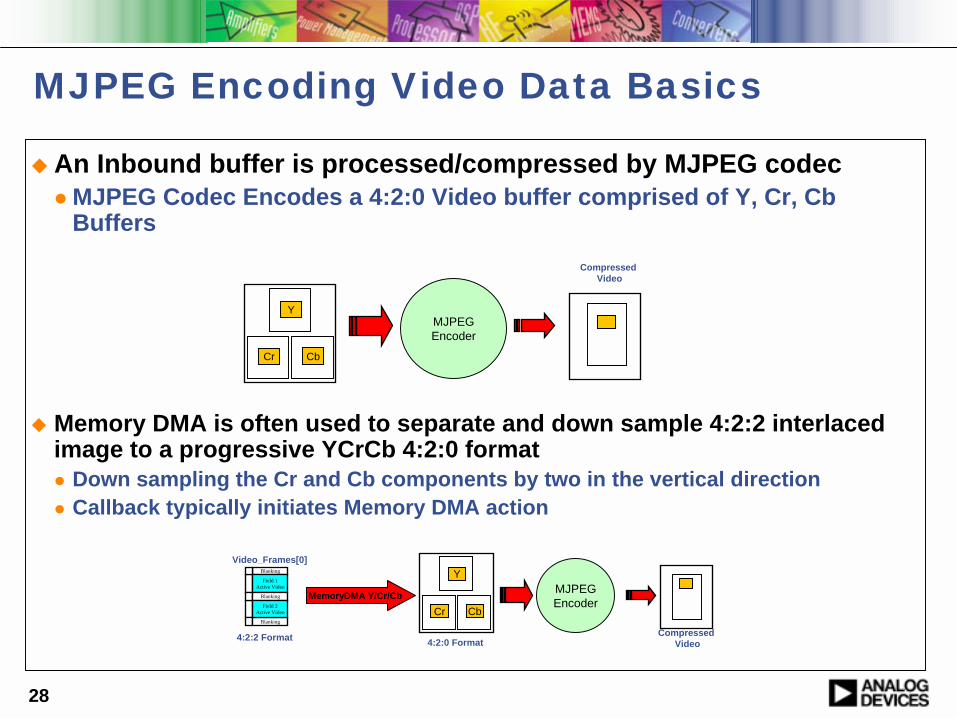
MJPEG Encoding Video Data Basics
! An Inbound buffer is processed/compressed by MJPEG codec" MJPEG Codec Encodes a 4:2:0 Video buffer comprised of Y, Cr, Cb
Buffers
! Memory DMA is often used to separate and down sample 4:2:2 interlaced image to a progressive YCrCb 4:2:0 format " Down sampling the Cr and Cb components by two in the vertical direction" Callback typically initiates Memory DMA action
MJPEGEncoder
Compressed Video
Y
Cr Cb
Y
Cr Cb
Blanking
Field 1Active Video
Blanking
Blanking
Field 2Active Video
Video_Frames[0]
MemoryDMA Y/Cr/Cb
4:2:2 Format 4:2:0 Format
MJPEGEncoder
Compressed Video
29
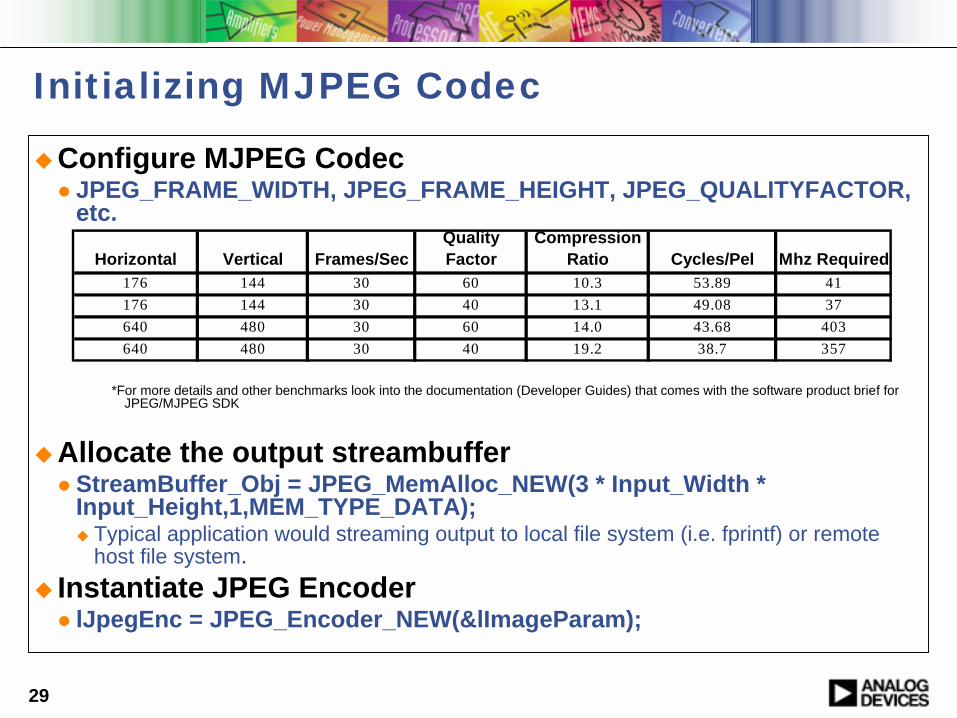
Initializing MJPEG Codec
!Configure MJPEG Codec" JPEG_FRAME_WIDTH, JPEG_FRAME_HEIGHT, JPEG_QUALITYFACTOR,
etc.
*For more details and other benchmarks look into the documentation (Developer Guides) that comes with the software product brief for JPEG/MJPEG SDK
!Allocate the output streambuffer" StreamBuffer_Obj = JPEG_MemAlloc_NEW(3 * Input_Width *
Input_Height,1,MEM_TYPE_DATA);! Typical application would streaming output to local file system (i.e. fprintf) or remote
host file system.! Instantiate JPEG Encoder
" lJpegEnc = JPEG_Encoder_NEW(&lImageParam);
Horizontal Vertical Frames/SecQuality Factor
Compression Ratio Cycles/Pel Mhz Required
176 144 30 60 10.3 53.89 41176 144 30 40 13.1 49.08 37640 480 30 60 14.0 43.68 403640 480 30 40 19.2 38.7 357
30
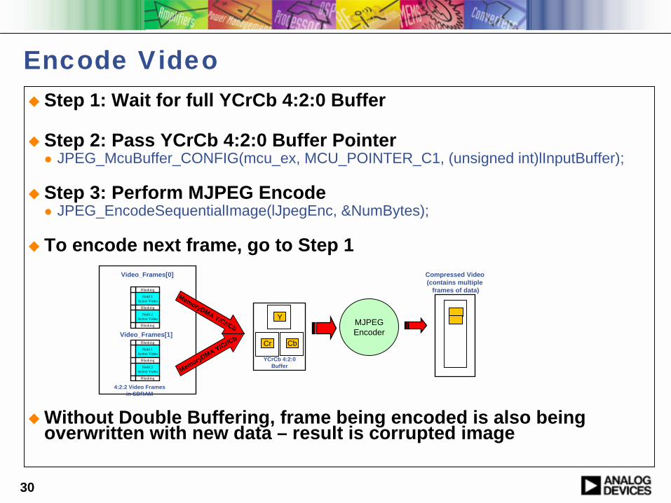
Encode Video! Step 1: Wait for full YCrCb 4:2:0 Buffer
! Step 2: Pass YCrCb 4:2:0 Buffer Pointer" JPEG_McuBuffer_CONFIG(mcu_ex, MCU_POINTER_C1, (unsigned int)lInputBuffer);
! Step 3: Perform MJPEG Encode" JPEG_EncodeSequentialImage(lJpegEnc, &NumBytes);
! To encode next frame, go to Step 1
! Without Double Buffering, frame being encoded is also being overwritten with new data – result is corrupted image
MJPEGEncoder
Y
Cr Cb
Blanking
Field 1Active Video
Blanking
Blanking
Field 2Active Video
Blanking
Field 1Active Video
Blanking
Blanking
Field 2Active Video
Video_Frames[0]
Video_Frames[1]
MemoryDMA Y/Cr/Cb
MemoryDMA Y/Cr/Cb
4:2:2 Video Framesin SDRAM
Compressed Video (contains multiple
frames of data)
YCrCb 4:2:0Buffer
31
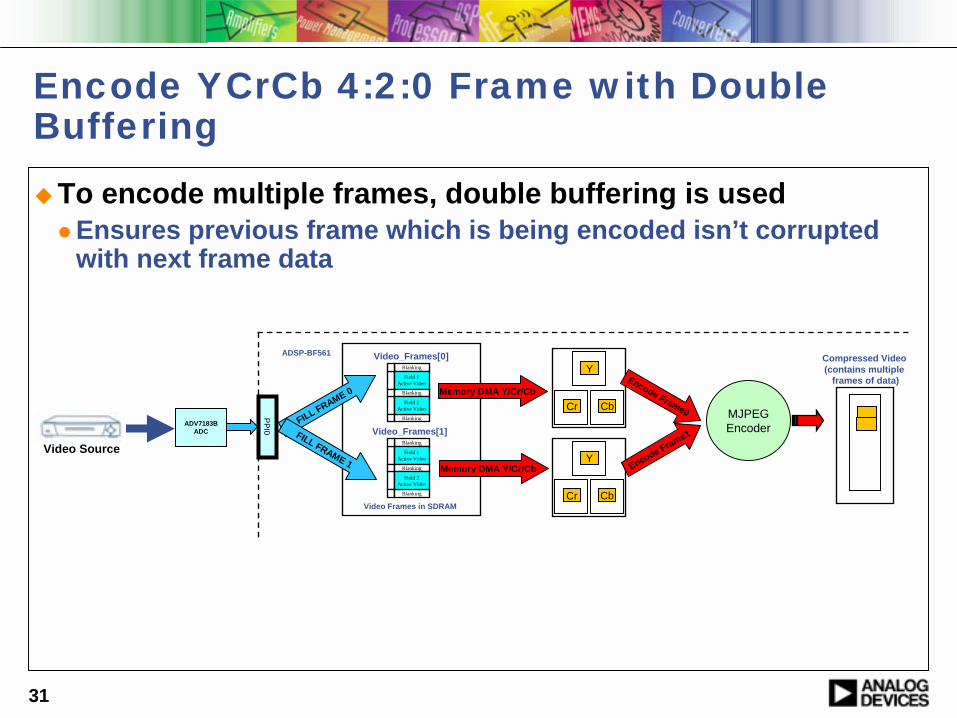
Encode YCrCb 4:2:0 Frame with Double Buffering!To encode multiple frames, double buffering is used
" Ensures previous frame which is being encoded isn’t corrupted with next frame data
PPI0ADV7183B
ADC
ADSP-BF561
MJPEGEncoder
Compressed Video (contains multiple
frames of data)Y
Cr Cb
Blanking
Field 1Active Video
Blanking
Blanking
Field 2Active Video
Blanking
Field 1Active Video
Blanking
Blanking
Field 2Active Video
Video_Frames[0]
Video_Frames[1]
Memory DMA Y/Cr/Cb
Memory DMA Y/Cr/Cb
Video Frames in SDRAM
Y
Cr Cb
Encode Frame1
Encode Frame0FILL FRAME 0
FILL FRAME 1Video Source

32
Outline for USB Sub-module
!Blackfin USB-LAN EZ-Extender
!Simple Blackfin-Host Data Transfers over USB 2.0

33
Blackfin USB-LAN EZ-Extender Hardware
!Adds USB 2.0 High speed connectivity to Blackfin" PLX NET2272 USB 2.0 High Speed Controller
!USB-LAN EZ-Extender plugs on to ADSP-BF533, ADSP-BF537, and ADSP-BF561 EZ-KITs
34
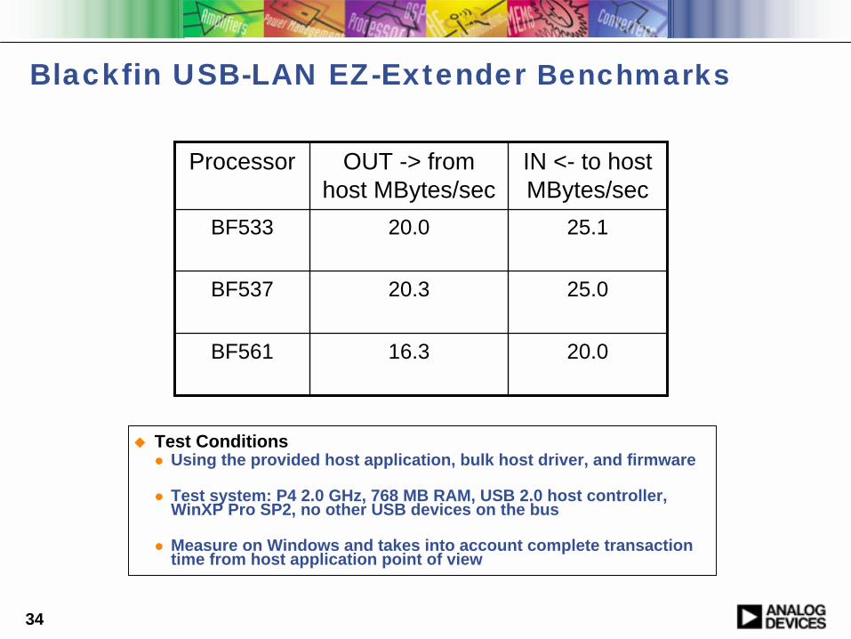
Blackfin USB-LAN EZ-Extender Benchmarks
! Test Conditions" Using the provided host application, bulk host driver, and firmware
" Test system: P4 2.0 GHz, 768 MB RAM, USB 2.0 host controller, WinXP Pro SP2, no other USB devices on the bus
" Measure on Windows and takes into account complete transaction time from host application point of view
20.016.3BF561
25.020.3BF537
25.120.0BF533
IN <- to host MBytes/sec
OUT -> from host MBytes/sec
Processor
35
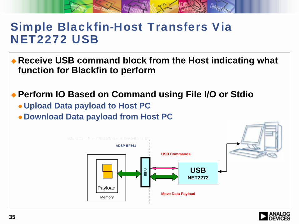
Simple Blackfin-Host Transfers Via NET2272 USB!Receive USB command block from the Host indicating what
function for Blackfin to perform
!Perform IO Based on Command using File I/O or Stdio" Upload Data payload to Host PC" Download Data payload from Host PC
Payload
USBNET2272
USB Commands
Move Data Payload
EB
IU
Memory
ADSP-BF561
36
Basic Commands Overview
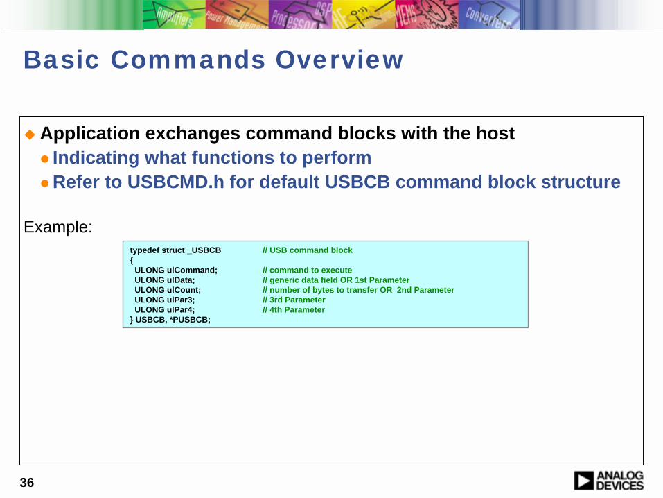
! Application exchanges command blocks with the host" Indicating what functions to perform" Refer to USBCMD.h for default USBCB command block structure
Example:typedef struct _USBCB // USB command block{
ULONG ulCommand; // command to executeULONG ulData; // generic data field OR 1st ParameterULONG ulCount; // number of bytes to transfer OR 2nd ParameterULONG ulPar3; // 3rd ParameterULONG ulPar4; // 4th Parameter
} USBCB, *PUSBCB;
37
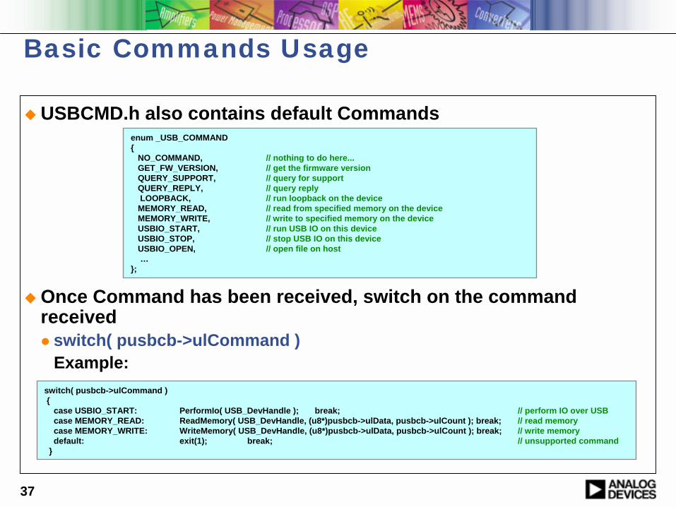
Basic Commands Usage
! USBCMD.h also contains default Commands
! Once Command has been received, switch on the command received" switch( pusbcb->ulCommand )
Example:switch( pusbcb->ulCommand ){
case USBIO_START: PerformIo( USB_DevHandle ); break; // perform IO over USBcase MEMORY_READ: ReadMemory( USB_DevHandle, (u8*)pusbcb->ulData, pusbcb->ulCount ); break; // read memorycase MEMORY_WRITE: WriteMemory( USB_DevHandle, (u8*)pusbcb->ulData, pusbcb->ulCount ); break; // write memorydefault: exit(1); break; // unsupported command
}
enum _USB_COMMAND{
NO_COMMAND, // nothing to do here...GET_FW_VERSION, // get the firmware versionQUERY_SUPPORT, // query for supportQUERY_REPLY, // query replyLOOPBACK, // run loopback on the deviceMEMORY_READ, // read from specified memory on the deviceMEMORY_WRITE, // write to specified memory on the deviceUSBIO_START, // run USB IO on this deviceUSBIO_STOP, // stop USB IO on this deviceUSBIO_OPEN, // open file on host…
};
38
Additional Inforamation on Blackfin USB
!Hardware schematics and layout data available on ftp site" ftp://ftp.analog.com/pub/tools/Hardware
!Blackfin USB firmware " Ships with latest VisualDSP++" C language examples - loopback and IO redirection" C language NET2272 driver – bulk and isochronous versions
!Windows host application " Ships with latest VisualDSP++" C/C++ example built with Microsoft Visual Studio .NET
39
Rapid Development of a MJPEG Video Encoder
40
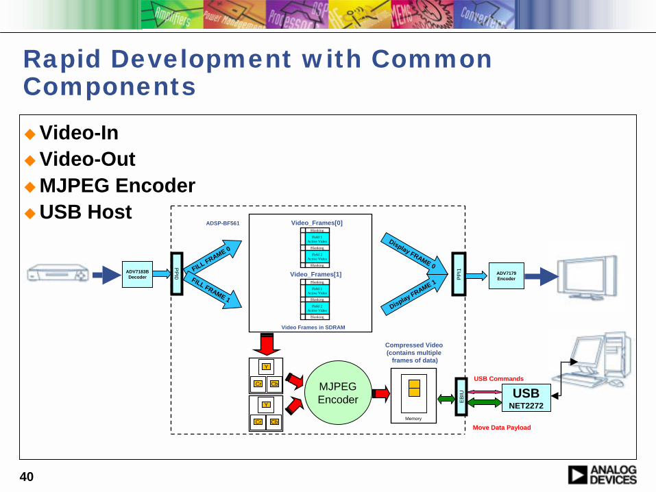
Rapid Development with Common Components!Video-In!Video-Out!MJPEG Encoder!USB Host
Blanking
Field 1Active Video
Blanking
Blanking
Field 2Active Video
Blanking
Field 1Active Video
Blanking
Blanking
Field 2Active Video
Video_Frames[0]
Video_Frames[1]
Display FRAME 1
Display FRAME 0
PPI
1
ADV7179Encoder
Video Frames in SDRAM
USBNET2272
USB Commands
Move Data Payload
EBI
U
MJPEGEncoder
Memory
Y
Cr Cb
Y
Cr Cb
Compressed Video (contains multiple
frames of data)
FILL FRAME 0
FILL FRAME 1
PPI0ADV7183B
Decoder
ADSP-BF561
41
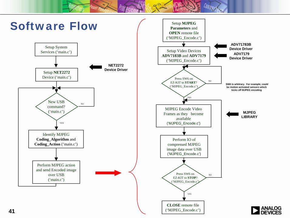
Software Flow
New USB command?(‘main.c’)
NO
Identify MJPEG Coding_Algorithm and
Coding_Action (‘main.c’)
YES
Setup NET2272Device (‘main.c’)
Setup System Services (‘main.c’)
Perform MJPEG action and send Encoded image
over USB(‘main.c’)
Press SW6 on EZ-KIT to START?(‘MJPEG_Encode.c’)
NO
MJPEG Encode Video Frames as they become
available(‘MJPEG_Encode.c’)
YES
Perform IO of compressed MJPEG image data over USB(‘MJPEG_Encode.c’)
Setup Video Devices ADV7183B and ADV7179
(‘MJPEG_Encode.c’)
Press SW6 on EZ-KIT to STOP?
(‘MJPEG_Encode.c’)
NO
YES
Setup MJPEG Parameters and
OPEN remote file (‘MJPEG_Encode.c’)
CLOSE remote file (‘MJPEG_Encode.c’)
NET2272 Device Driver
ADV71783B Device Driver
ADV7179Device Driver
MJPEG LIBRARY
SW6 is arbitrary. For example, could be motion activated sensors which
kicks off MJPEG encoding
42
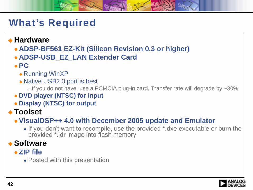
What’s Required!Hardware
" ADSP-BF561 EZ-Kit (Silicon Revision 0.3 or higher)" ADSP-USB_EZ_LAN Extender Card" PC
!Running WinXP!Native USB2.0 port is best
− If you do not have, use a PCMCIA plug-in card. Transfer rate will degrade by ~30%" DVD player (NTSC) for input" Display (NTSC) for output
!Toolset" VisualDSP++ 4.0 with December 2005 update and Emulator
" If you don’t want to recompile, use the provided *.dxe executable or burn the provided *.ldr image into flash memory
!Software" ZIP file
" Posted with this presentation
43
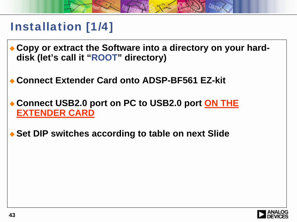
Installation [1/4]
!Copy or extract the Software into a directory on your hard-disk (let’s call it “ROOT” directory)
!Connect Extender Card onto ADSP-BF561 EZ-kit
!Connect USB2.0 port on PC to USB2.0 port ON THE EXTENDER CARD
!Set DIP switches according to table on next Slide
44
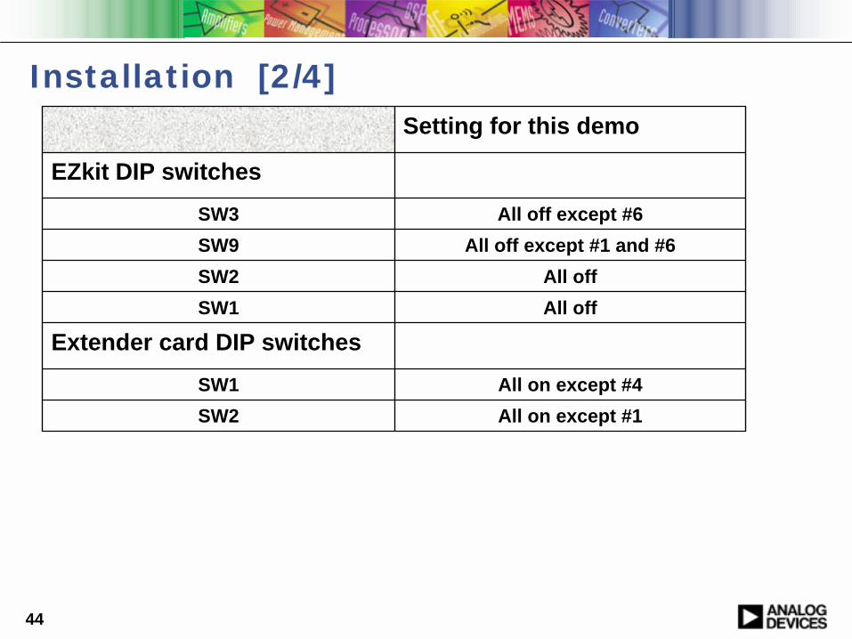
Installation [2/4]
All on except #1SW2All on except #4SW1
Extender card DIP switchesAll offSW1All offSW2
All off except #1 and #6SW9All off except #6SW3
EZkit DIP switches
Setting for this demo
45
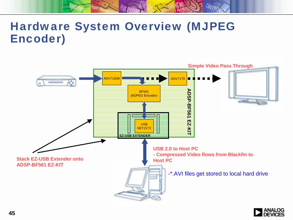
Hardware System Overview (MJPEG Encoder)
BF561(MJPEG Encoder)
ADV7179ADV7183B
USBNET2272
USB 2.0 to Host PC- Compressed Video flows from Blackfin to Host PC
EZ-USB EXTENDER
-*.AVI files get stored to local hard drive
Simple Video Pass Through
Stack EZ-USB Extender onto ADSP-BF561 EZ-KIT
AD
SP-BF561 EZ-K
IT

46
Installation [3/4]
!Connect the NTSC display to the “Video Out” Connector J6 on ADSP-BF561 EZ-Kit
!Connect the NTSC DVD player to the “Video In” Connector J6 on ADSP-BF561 EZ-Kit
!Power DVD Player and Display
J6 on ADSP-BF561 EZ-Kit
47
Installation [4/4]
!Power the EZ-Kit!Start VisualDSP++!Load the Image File into flash memory
" Use VisualDSP’s “flash programming tool”" Image file is “ROOT\codec_blkfn\jmjpeg_app\BF561\bin
!Exit VisualDSP++ and reset the EZ-kit
!Windows should now detect a new USB Device" Follow the prompts to install the device driver
" Specify the path to the device driver" Device Driver is located in “ROOT\codec_host\hostdriver”
directory" This step needs to be done only once" Windows will remember device driver next time

48
USAGE [1/3] – General!Open a DOS prompt Terminal on your PC
!Generally under Start->All Programs->Accessories !Change Directory to “ROOT\codec_host\hostapp” directory
!With DOS’s “cd” command (if necessary, switch to the hard-disk drive by typing “C:”)
!The “hostapp.exe” application is the main control for the Demo Application that is running on the DSP.
!A few tests:!Type “hostapp –h” and press “enter” - what happens?!Type “hostapp –a” - will tell you if and how many DSPs are connected!Type “hostapp –v” - more information about the application
! If the “hostapp” detects a device, you are ready to proceed!
49
USAGE [2/3] - General
A few general explanations:" Open an Explorer Window at
" “ROOT\images”−Call this the “work directory”
" “ROOT\images\MJPEG”− Target directory where encoded MJPEG *.AVI files will be stored
The application uses File I/O to upload Payload to the Host PC" DISPLAYs information about the encoding/decoding process" Follow instructions on the terminal CAREFULLY
" DO NOT TYPE in the terminal unless instructed to" Accidentally press a key at the wrong time will abort the program. Just
press the reset button on the EZ-kit
50
USAGE [3/3] – MJPEG ENCODER! Open the specification file in the work directory
! mjpeg_encoder_spec.txt
! Each line specifies a target MJPEG (*.avi) file to be encoded from a Video source! Type the name: for instance mymovie! Type the size (Horizontal Vertical): for instance 320 240! Type the encoding quality factor (0 [least] – 100 [max])
! Repeat for as many recordings/files you like to takeExample: DISPLAY_MPEG_TEST1 352 288 60
DISPLAY_MPEG_TEST3 640 480 70
! Save the file
! Run ENCODER from the Host PC terminal:! Type “hostapp –m e” - Sets the DSP application to (m)jpeg (e)ncoding! Type “hostapp –u” - Starts encoder application
" NOW (as instructed) press button on the EZ-kit ! Press to start recording! Press to stop recording! Press ENTER on the keyboard to move to the next file! Repeat for each file you specified in the steps above
! Play the files !" Find files specified above in MJPEG directory in the work directory" Play the files by double-clicking on them
51
Additional Information
!Blackfin USB firmware" Ships with latest VisualDSP++" C language examples - loopback and IO redirection" C language NET2272 driver – bulk and isochronous versions
!Windows host application " Ships with latest VisualDSP++" C/C++ example built with Microsoft Visual Studio .NET
!For questions, click “Ask A Question” button or send an email to [email protected]