rapid prototyping - 3d printer
TRANSCRIPT

Rapid Prototyping - 3D Printer
A Baccalaureate thesis submitted to the School of Dynamic Systems
College of Engineering and Applied Science University of Cincinnati
in partial fulfillment of the
Requirements for the degree of
Bachelor of Science
in Mechanical Engineering Technology
by
Garrett Alan Ford
April 2013
Thesis Advisor: Professor Muthar Al-Ubaidi, Ph. D

ii
ACKNOWLEDGEMENTS
First off I would like to thank my Family and friends for supporting me in the pursuit of
my degree in Mechanical Engineering. It has been a long road and has taught me a lot about
life and staying positive. The professors at the Applied Science College have been great and
a knowledgeable group of professors that are working for the students.
TABLE OF CONTENTS
ACKNOWLEDGEMENTS ...................................................................................................... II
TABLE OF CONTENTS .......................................................................................................... II
LIST OF FIGURES ................................................................................................................ III
LIST OF TABLES .................................................................................................................. III
ABSTRACT ............................................................................................................................ IV
INTRODUCTION .................................................................................................................... 1
MAIN COMPONENTS OF A 3D PRINTER ................................................................................................................ 1
EXISTING PRODUCTS .......................................................................................................... 2
FEATURE SURVEY AND RESULTS ......................................................................................................................... 5 PRINTER DESIGN OBJECTIVES ............................................................................................................................. 6 ENGINEERING CHARACTERISTICS ....................................................................................................................... 7
CONCEPT GENERATION AND SELECTION ..................................................................... 8
CALCULATIONS .................................................................................................................. 10
CALCULATING LEAD SCREW FORCES ............................................................................................................... 10 CALCULATING LOAD FORCES ON THE BUILD PLATFORM ................................................................................. 11 CALCULATING TORQUE AND HORSEPOWER FOR X & Y AXIS MOTORS ............................................................ 13
ASSEMBLY DESIGN DETAILS .......................................................................................... 14
THE FRAME ...................................................................................................................................................... 14 THE BUILD PLATFORM ..................................................................................................................................... 16 THE FILAMENT APPARATUS ............................................................................................................................. 17
TESTING ................................................................................................................................ 17
SCHEDULE AND BUDGET ................................................................................................. 18
DRAWINGS ........................................................................................................................... 18
COMPONENET SELECTION .............................................................................................. 18
WORKS CITED ....................................................................................................................... 1
APPENDIX A - RESEARCH ................................................................................................... 1
APPENDIX B – SURVEY & RESULTS ................................................................................. 1
APPENDIX C – QUALITY FUNCTION DEPLOYMENT DIAGRAM ................................ 1
APPENDIX D – PRODUCT OBJECTIVES ............................................................................ 1

iii
APPENDIX E - SCHEDULE ................................................................................................... 1
APPENDIX F - BUDGET ........................................................................................................ 1
APPENDIX G - DRAWINGS .................................................................................................. 1
APPENDIX H – PURCHASED COMPONENTS ................................................................... 4
LIST OF FIGURES Figure 1 - MakerGear Mosaic Printer (1) ................................................................................. 1 Figure 2 - Dimension 1200es Series ......................................................................................... 2
Figure 3 - Zcorp 3D Printer ...................................................................................................... 3 Figure 4 – MakerGEAR Mosaic Printer ................................................................................... 3 Figure 5 – Botmill 3D Printer ................................................................................................... 4
Figure 6 – Makerbot Replicator 3D Printer .............................................................................. 4 Figure 7 – Closed Design Concept ........................................................................................... 8 Figure 8 – Open Design Concept .............................................................................................. 9
Figure 9 – Acme Calculator Results ....................................................................................... 11 Figure 10 – FEA Fixed Geometry .......................................................................................... 12
Figure 11 – FEA Load Conditions .......................................................................................... 12 Figure 12 – FEA Stress Results Top View ............................................................................. 13 Figure 13 – FEA Displacement Results .................................................................................. 13
Figure 14 – Front Iso Printer Frame ....................................................................................... 15 Figure 15 - Back Iso Printer Frame......................................................................................... 15
Figure 16 – Bottom Iso Printer Frame .................................................................................... 16 Figure 17 – Printer Bed Top Iso ............................................................................................. 16
Figure 18 – Printer Bed Bottom Iso ........................................................................................ 17
LIST OF TABLES Table 1 – Customer Importance ................................................................................................ 5
Table 2 – Engineering Characteristics ...................................................................................... 7 Table 3 – Waiting Rated Method Results ................................................................................. 9

iv
ABSTRACT
The 3D printing world has been in its infancy and has been growing in there last few
years. However, with all of the growth there has not been a printer that would get the best
out of both cost and build size. The following design is able to do so. Using general shop
and fabrication practices this printer design is a low cost and large envelope 3D printer for
personal or commercial use.
An engineering group was surveyed to determine the needs of a 3D printer. The group
surveyed showed that Reliability, Easy to Use, and Accuracy are the main components that
are desired in a 3D printer. Design concepts were thought of to attain the concepts and using
product development methods a Open design concept was accepted. This would allow for
easy maintenance and a more compact design for the printer.
With the design set the designer looked to determine the lead screw forces needed to life
and lower the load. This was based on Acme Lead Screw calculations and designed for
accuracy and a smooth movement. The X and Y axis motors were selected based upon the
GatesDF program which gave the correct horsepower and torque required to move the
components used in printing.
As a result parts that are used for this printer will need to be able to use as a solid
concept that can be a test fit and allow for accurate conclusions of the design to be done. The
parts created will measure out to the dimensions of the solid models ±.005. This will show
an accurate depiction of the solid model in the real world. The frame will be comprised of
steel and powder coated to keep rust from forming. The filament for the printer will need to
be feed cleanly to obtain the reliability of the printer and to maintain the efficiency of the
printer.

Rapid Prototyping 3D Printer Garrett Ford
1
INTRODUCTION
In the fast paced world of business reducing the time to market keeps you ahead of your
competition. Having the capability to reduce design iterations between engineering and
sales/marketing allows new products to get to market faster. Being able to take advantage of
3D printing can also reduce Engineering R&D material costs as well as labor cost. Having
the ability to make a functioning part that can be used to check fit/form/function in hours
rather than days allows for a more flexible design process. 3D printing has been increasingly
growing in usage since 2003, but the cost has not come down enough in order for small
market companies to use the technology.
Current personal desktop 3D printers have a smaller 5” cube, which reduces the number
of parts that can be made with the printer. By increasing the size envelope of the printer
company’s can increase the amount of parts that can be made. The proposal is to design a
cost effective 3D printer that can create parts within a 10-12” cube. Fecon Inc. will supply
the funding for the project and will use the printer as an R&D tool for product development.
MAIN COMPONENTS OF A 3D PRINTER
The general components of a 3D printer are relativity the same from one to the other.
Below is Figure 1 that will show the main components of the 3D printer and will give a brief
explanation of what the components are used for in the daily function of the printer.
Figure 1 - MakerGear Mosaic Printer (1)
Build Table Platform Axis Rail Build Table
Frame
Axis Motor Belt
Heating Element

Rapid Prototyping 3D Printer Garrett Ford
2
The 3D printer is comprised of Motors, Rails, Heating Elements, Platforms, Belts, and
Filament. The main purpose of the Motors, Rails, and Belts are to provide motion for the
three axis of movement for the printer X-Y-Z. Those motors are in connection with a mother
board (Not Shown) that takes signals from a computer connected through USB to the printer.
This allows for the precise movement of the heating Element at the top of the printer to pull
in Filament in order to melt the plastic into the exact location that is needed to produce a
physical model from a 3D program. The filament is usually PLA or ABS plastic both of
which are used commonly in 3D printer applications. The build platform is used to hold the
build table that is heated using PCB board to allow for proper placement of the filament on
the table. In general these components are used in multiple variations by different companies
to make a 3D printer. Depending on the range of wants by the customer it can reduce or
improve cost in the product. There are several different manufactures that make 3D printers
for either personal or commercial use in the marketplace.
EXISTING PRODUCTS
The 3D Printer has caught on as a viable way to develop rapid prototypes for company
and personal use. While the vast majority of technology has expanded the price for a large
envelope machine has maintained its high cost and has been out of reach for mid level
companies.
In the research that was completed there are several examples of large commercial 3D
printers such as the Dimension 1200es Series (1) machines that have an envelope of
minimum of 10” x 10” x 12 inches (1). However the large size of the machine and the price
of around $24,900 (1) is a high price for a company to sink into and it not cover the cost of
the machine for years to come.
Figure 2 - Dimension 1200es Series

Rapid Prototyping 3D Printer Garrett Ford
3
With this the research continued and the next machine that was found was the Zcorp 3D
Printer. This machine has a smaller starting price tag of $14,900 (2), but with the smaller
price tag comes a smaller envelope.
Figure 3 - Zcorp 3D Printer
The Makergear Mosaic 3D printer is a cost effective printer that has a build envelope of
5” x 5” x 5” (3). It comes in a kit that cost $989.00 (3)in which they send to you with most
of the electrical components assembled and they leave you to do the build up of the machine.
This makes the assembly a bit tedious and in some instances discourages an individual during
the build of the machine. They also leave it up to the end user to find a place for the power
converters which cause a hazard once the unit is complete as they just lay anywhere around
the unit once it is in use. This unit also leaves it up to the end user to find a way to properly
allow the filament to feed into the system without binding and causing errors in the printed
model.
Figure 4 – MakerGEAR Mosaic Printer

Rapid Prototyping 3D Printer Garrett Ford
4
Another personal printer is the Botmill unit which comes in at $999.00 (4)and has a
build envelope of 8” x 8” x 5” (4). This unit while it has a larger envelope at about the same
price as the Makergear Mosaic based on the Figure 2 (3) it looks very complicated to build
and to maintain the leveling of the machine.
Figure 5 – Botmill 3D Printer
The Makerbot Replicator 3D printer which comes to the end user as a completely built
unit and makes the setup of the machine quite simple. It comes in at a cost of $1,749.00
(5)and a build envelope of 8.9” x 5.7” 5.9” (5) which is still smaller than that of a large
commercial unit in which the project will be completed for.
Figure 6 – Makerbot Replicator 3D Printer

Rapid Prototyping 3D Printer Garrett Ford
5
FEATURE SURVEY AND RESULTS
The engineering group at FECON was surveyed to determine what features would be the
most important in the 3D printer that would be used. The department consists of eight
individuals composed of Engineers and engineering co-ops. The survey covered a range of
topics such as cost, maintenance/service, Build time, and accuracy. The results of the survey
were put into a QFD (Quick Function Diagram), which allows the designer of the 3D printer
to evaluate and determine how the end design will operate for the end customer.
Table 1 – Customer Importance
The feature of Reliability (12%) came in with the largest customer importance as well as
the largest relative weight when the designer’s multiplier was added. The designer felt that
the surveyed results showed that the level of reliability was at an adequate level for the
feature. Just as the accuracy(11%) and easy to use (10%) features were highly valued during
the survey there is no need for the designer to increase the importance. The feature of cost
effectiveness (10%) did need some designer input into improving the importance of the cost
of the printer. If the printer is not cost effective then there is no need to get it or other options
may be explored.
Having the unit easy to maintain (10%) was a feature that got a high survey result, which
lead the designer to leave that unaffected. The unit design would lead to not having a high
maintenance cost and would allow for minimal adjustments needed after the first initial
setup. The next two features were safety (9%) and Plug N’ Play (9%) the designer looked at
other units on the market and felt that the safety of the unit can be accurately shown with
warnings to not go toward the machine while in use and felt the surveyors gave it an accurate
score in terms of importance. When the designer looked into the other units on the market
the Plug N’ Play feature was one the designer considered a place for improvement. Looking
at others on the market some leave items out in the open and not in a compact unit with

Rapid Prototyping 3D Printer Garrett Ford
6
minimal outside connections. The efficiency (8%) of the unit was another trait that was
looked to be improved by the designer. The units out there leave it up to the end user to
come up with a way to hold the filament which can lead to problems with the model as the
plastruder can leave gaps in the model and hurts efficiency.
The last three features Easy to Build (7%), Compact (7%), and Quiet (7%) all had a low
rating with the surveyors. The designer looked at these features to improve the printer
overall and still maintain the function of the printer and customer satisfaction. Having the
unit easy to assemble will only help the end user enjoy the product. Also the printer will
work in a office environment in a typical fashion so having a quiet unit that doesn’t cause
distractions is very beneficial.
PRINTER DESIGN OBJECTIVES
The following objectives’ are shown in order of importance as shown in Table 1, which
are needed to perform the function of a 3D printer. The objectives are paired with
engineering characteristics that with allow the design to be measured upon completion of the
project. Using engineering characteristics will facilitate a good sound design and determine
the best feasible solution to the design problem.
1.) RELIABLE (12%)
a) Machine will print without the presence of a person
b) Filament will feed cleanly and without binding.
2.) ACCURATE (11%)
a) Parts created will measure out to the dimensions of the solid models ±.005.
3.) EASY TO USE (10%)
a.) Operator will be able to operate machine with a procedure of less than 10
steps.
4.) COST EFFECTIVE (10%)
a) Prototype cost will be $2000-$3000.
5.) EASY TO MAINTAIN (10%)
a) Bed will only need level checks annually by using basic hand tools
b) Frame will be powder coated to prevent rust
6.) SAFE (9%)
a) Shafts of motors will have guards
b) Exposed wires will be loomed
c) Power supply’s will be enclosed in the unit
d) Will calculate load rating on Motors to assure they don’t exceed the motor
limit.
7.) PLUG N’ PLAY (9%)

Rapid Prototyping 3D Printer Garrett Ford
7
a) Machine will turn on by plugging in one plug and flipping a switch.
b) Files will be maintained on a network connected to a computer/laptop.
8.) EFFICIENT (8%)
a) Software will allow configuration to have any model to print in less than 10
hrs.
9.) EASY TO BUILD (7%)
a) Machine will be made of subassemblies to allow for assembly with basic hand
tools.
b) Unit Assembly time will be below 5 hours.
10.) COMPACT (7%)
a) Machine will not take up more space than a desktop printer.
11.) QUIET (7%)
a) Unit will be covered to reduce noise levels.
ENGINEERING CHARACTERISTICS
Table 2 – Engineering Characteristics

Rapid Prototyping 3D Printer Garrett Ford
8
For the engineering characteristics and emphasis was put on the reliability and accuracy
based on the surveys from the customer. There are several of the characteristics that were
put into the QFD that would affect both the reliability and the accuracy. Both the filament
apparatus and leveling method will affect the apparatus due to the fact that how the filament
is fed through the heating element and the table that is under the element will help in the
quality of parts that are a product of the printer. If the filament is not fed smooth then the
prints will not fuse together well and will come apart.
The metal finish and the build envelope are also a contributing factor in the design of the
printer. The build envelope needs to be big enough for common parts to not need to be
scaled down. This also leaves the ability for components to be tested before actually being
made with expensive materials. This reduces time to market and give the ability for
iterations to be done lease expensively.
CONCEPT GENERATION AND SELECTION
With the surveys complete and features ordered with the importance the designer
looked to have concepts to look through to allow for a selection of the best concept to use as
the final design.
The concepts were based on looking at a variety of the other printers on the market.
The first concept will be referred to as the Closed Design. This is because the design will be
closed up and no parts will move outside of the housing. This will help with controlling the
sound and keeping the unit quiet, but will not allow for easy access to maintenance of the
machine. The closed design will also cause the unit to become increasingly bigger as it must
be able to account for the 12” build envelope that will be used for the printer. With the large
envelope the printer will also weigh more than the second concept, which will increase the
cost of the printer and make it less cost effective than the other.
Figure 7 – Closed Design Concept

Rapid Prototyping 3D Printer Garrett Ford
9
The second concept design will be referred to as the Open Design. This design will
allow for easy access to maintenance items and also have a smaller footprint due to the fact
that the printer bed will allow for the free movement of the bed without restriction of the
surrounding housing. This concept however does cause a safety issue and must be labeled
adequately in order to keep individuals from getting hurt during the operation of the printer.
Also this design will allow for less material thus resulting in the reduction of cost.
Figure 8 – Open Design Concept
The design concept what chosen using the weighted rating method and thus given
adequate weights based on the Customer surveys. The concepts were then rated using a five-
point scale (0-4) and then multiplied by the weight to find the total score of each concept. In
this instance the Open design gained the higher number and was chosen to move on to the
design and manufacturing steps in the project.
Closed
Design
Open
Design
Weight Rating
Weighted
Rating Rating
Weighted
Rating
Reliable 0.12 3 0.36 3 0.36
Accurate 0.11 3 0.33 3 0.33
Easy to Use 0.10 3 0.3 4 0.4
Cost Effective 0.10 1 0.1 4 0.4
Easy to
Maintain 0.10 1 0.1 3 0.3
Safe 0.09 3 0.27 2 0.18
Plug N' Play 0.09 3 0.27 3 0.27
Efficient 0.08 3 0.24 3 0.24
Easy to Build 0.07 2 0.14 3 0.21
Compact 0.07 1 0.07 3 0.21
Quiet 0.07 4 0.28 2 0.14
Totals 1 2.46 3.04
Table 3 – Waiting Rated Method Results

Rapid Prototyping 3D Printer Garrett Ford
10
CALCULATIONS
CALCULATING LEAD SCREW FORCES
The design of the lifting mechanism for the build table was built on the principle of the
lead screw and using the force of an electric motor to develop the required torque in order to
lift the build table to the appropriate level for use. By finding the total weight of what is to
be lifted the motor specifications can then be found. The Density of PLA plastic which is a
common used material in rapid prototyping is 0.0477 (7).
The model weight is based on a solid 6” cube which is:
Safety Factor = 2
The lead screw is a precision acme threaded rod with a standard size of 3/8”-8 and a
speed ratio of 4:1. This will allow for a larger range of movement as 1 turn will move ½” of
linear rotation. The ANSI B1.5-1988 standard (7) is used to find the torque required to raise
and lower a load. The torque required to lift the load is from the equation:
Using the Calculator that is found at the Mead Info website and inputting the design
data:

Rapid Prototyping 3D Printer Garrett Ford
11
Number of Thread starts = 4
The Results were:
Figure 9 – Acme Calculator Results
It is typical for electric motors to be rated in oz.-In so a conversion is necessary for the
output from the calculator due to the units being Lb-In. One Lb-In equals 16 Oz-In
Torque Required to Raise the Load:
Torque Required to Lower the Load:
CALCULATING LOAD FORCES ON THE BUILD PLATFORM
The design of the build platform is also a part of the design that needs to be checked to
make sure that the weight of the models will not distort the build platform causing problems
with the printer during operation. The following analysis was done using Solidworks

Rapid Prototyping 3D Printer Garrett Ford
12
Simulation and the inputs that were put into solidworks were as follows.
The unit went through a static analysis of the amount of load that the build plate will undergo
during the most extreme situation. Figure 10 shows the fixed geometry of the unit which are
the guide rails and the lead screw.
Figure 10 – FEA Fixed Geometry
The load was then applied to the unit. As calculated above the load in the most extreme case
would be ~36 lbs. Figure 11 shows the load being applied to the top of the guide rail carrier.
While the build table will be larger than the 12” cube the unit will be designed for the amount
of load will all fall on the guide rail carrier.
Figure 11 – FEA Load Conditions
The results yielded a max stress of around 6.3 ksi in a small section on the bottom of the unit
in the worst case scenario. This was deemed adequate by the designer and found to be
negligible due to the fact that the stress is only located in a small section of the model
whereas the rest of the model was not above 2.1ksi. The design also received a safety factor
of 1.8 which coincides with the calculated safety factor of 2.

Rapid Prototyping 3D Printer Garrett Ford
13
Figure 12 – FEA Stress Results Top View
From here the designer looked to the displacement of the model based on the given load.
Figure 13 shows the displacement of the model which did not exceed 0.001” of an inch. It is
important to note that the max displacement occurred on the outside edge due to the fact that
the load was not applied directly in the center of the rail.
Figure 13 – FEA Displacement Results
CALCULATING TORQUE AND HORSEPOWER FOR X & Y AXIS MOTORS
From the Sli3er software the average acceleration of the X and Y axis motors is 2000
mm/ . Given the acceleration the designer then found the velocity of the belt and then the
design RPM.

Rapid Prototyping 3D Printer Garrett Ford
14
⁄
Converting Rev/s to RPM:
Using the Gates DFpro program the designer inputted the calculated RPM needed to
move the X and Y axis. The program yielded the results that a motor with the equivalent
horsepower of 0.003 would be adequate to move both the X and Y axis components.
Calculating the torque needed to move the X and Y axis the designer took the 168 RPM and
calculated the horsepower.
Converting lb-in to oz-in:
With those results the designer found a 19 oz-in Motor to be used for both the X and Y axis
motors. Motor specifications can be seen in Appendix H.
ASSEMBLY DESIGN DETAILS
THE FRAME
The frame for the 3D printer will be made of steel and bent and welded into together.
The unit will weight approximately 73 lbs when fully assembled. The components were
designed for a stationary office environment. It will be powder coated to be rust resistant and
maintain a presentable appearance. The frame will also have slot and tabs in order to give
direct placement of critical parts within the frame.

Rapid Prototyping 3D Printer Garrett Ford
15
Figure 14 – Front Iso Printer Frame
Figure 15 - Back Iso Printer Frame
The frame will also enclose all of the electronic parts as well as the parts for power
generation. A power cord will be the only needed connection to the unit and a USB will be
the only needed connection to the unit for a laptop or desktop computer to connect to the
printer.
Parts will be tabbed and slotted into
to give accurate placement of integral
parts.
Frame will be powder coated to keep
rust and oxidation from occurring
during use. The frame should last the
life of the machine without
replacement.
Z-Axis motor will be housed in the
bottom of the frame for safety.
All wires will be routed through the
frame and will not interfere with the
operation of the machine.

Rapid Prototyping 3D Printer Garrett Ford
16
Figure 16 – Bottom Iso Printer Frame
THE BUILD PLATFORM
The build platform will be made from steel in order to maintain the rugged construction
of the frame. The Build frame will be able to be leveled and stay leveled in order to maintain
accuracy that is needed in a rapid prototyping environment. The Build table will be leveled
by three springs (INFO on Springs) and consist of three layers. First, being the leveling pad
which will hold the flat headed screws for the platform. Second, will consist of the PCB
board that will be used to heat the build table to allow for the plastic to set correctly as it is
being placed on the unit. Third will be the table itself which will act as the main platform to
hold the model.
Figure 17 – Printer Bed Top Iso
All electrical components will be
housed underneath the unit for
cleanliness.
Build platform will have heater
board to maintain constant
temperature of bed during
operation.

Rapid Prototyping 3D Printer Garrett Ford
17
Figure 18 – Printer Bed Bottom Iso
THE FILAMENT APPARATUS
The filament being fed into the system will be completed by having the filament hang
from above the unit to allow for smooth release of the filament from the roll on which it is
housed. This will take away the need for the customer to have to check on the machine to
make sure the filament is being fed properly. The arm will be removable in order to reduce
the height for shipment.
TESTING
Testing of the Printer will be comprised of using simple and complex models supplied
by FECON, Inc. as well as models that may be found online. This will verify that the printer
will function at the highest level and be able to make the most complex models accurately.
The Designer will test both PLA and ABS filament to verify which is the best to use. Also
the unit will be tested under supervision and unsupervised to verify that the unit can be left
Rail structure on the bottom
will provide support for the
frame.
Roll will be held on the brace
by a welded frame piece and
then supported by a gravity
held piece on the bottom.

Rapid Prototyping 3D Printer Garrett Ford
18
overnight to make a model and not fail. This will verify that the unit can be efficient and
reliable under any condition.
SCHEDULE AND BUDGET
Once the above engineering characteristics were agreed upon by the project advisor a
schedule was then developed which can be seen in Appendix E. The design will be complete
before the end of the semester. The Frame will be the first component that is designed
following by the build housing, Sound housing, and Filament feeder. After the winter break
most of the manufacturing will be taken place at Fecon Inc. where they have a Laser, Press
Brake, Lathe, and other equipment that can complete the components necessary for the
manufacture of the 3D printer. The Budget was then developed based on preliminary cost of
the components. The Budget can be found in Appendix F.
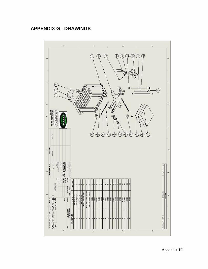
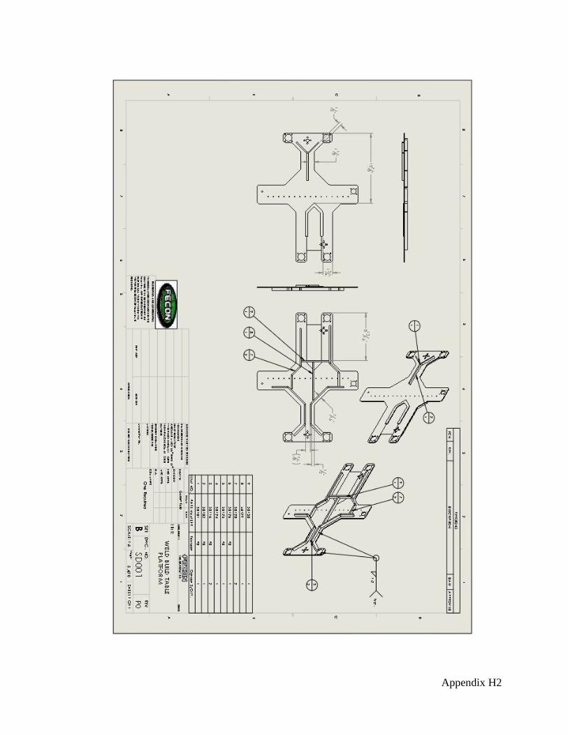
DRAWINGS
Exploded Assembly, Weld Drawings for the frame and build platform that follow
geometric tolerance guidelines can be found in Appendix G.
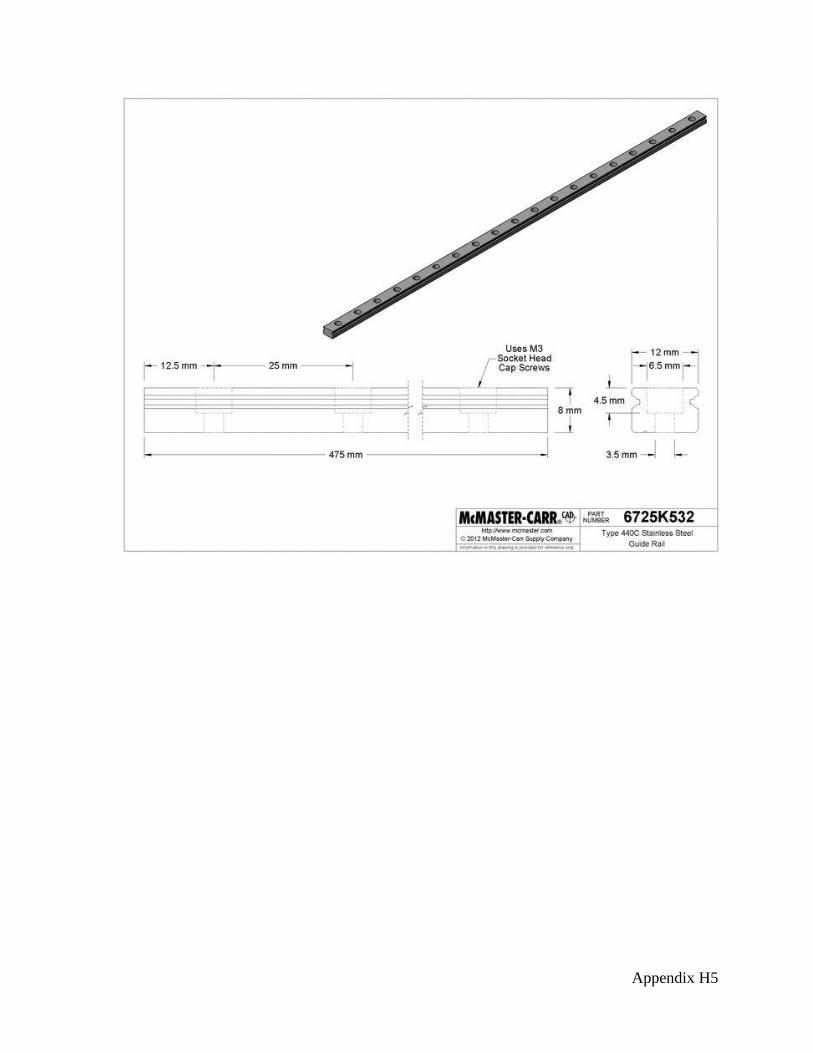
COMPONENET SELECTION
When applied standard components were selected to achieve the results that were found
during the calculations. The components were selected based on those specifications and the
designer’s knowledge of the product. Refer to Appendix H for drawings of some of the
purchased components for the printer.

Rapid Prototyping 3D Printer Garrett Ford
1
WORKS CITED
1. Brown, Rich. 3D Printer Build Week: Day Two. Cnet. [Online] [Cited: 2012 йил 7-
September.] http://news.cnet.com/8301-17938_105-57377993-1/3d-printer-build-week-day-
two/.
2. Dimension. 1200es Series 3d Printers. [Online] Stratasys, Inc., 2012 йил. [Cited: 2012
йил 14-Feburary.] http://www.dimensionprinting.com/3d-printers/3d-printing-1200es.aspx .
3. Zprinter 650. Anvil Prototype & Design. [Online] Anvil Prototype. [Cited: 2012 йил 6-
September.] http://store.makerbot.com/replicator-404.html.
4. M Series 3D Printers. Makergear.com. [Online] MakerGear LLC. [Cited: 2012 йил 14-
Feburary.] http://www.makergear.com/products/m-series-3d-printers.
5. BotMill 3D Printers. BotMill. [Online] BotMill. [Cited: 2012 йил 6-September.]
http://botmill.com/index.php/3d-printers/axiskit.html.
6. The Replicator. MakerBot Store. [Online] MakerBot. [Cited: 2012 йил 6-September.]
http://store.makerbot.com/replicator-404.html.
7. Compostable PLA Blend. MatWeb. [Online] [Cited: January 31, 2013.]
http://www.matweb.com/search/DataSheet.aspx?MatGUID=96a20b960a9f4e0499ec0828d61
28771.
8. ACME Lead Screw Torque Calculator ANSI B1.5-1988. Mead Info. [Online] 2008 йил.
[Cited: 2013 йил 3-January .] http://www.meadinfo.org/2009/07/acme-lead-screw-torque-
calculator.html.
9. Stanley, Jeff. VP of Engineering and Operations. Lebanon, 2012 йил 11-September.
10. Silverbrook, Kia. 3-d product printing system. 7373214 United States of America, 2008
йил 13-May. Mechanical.

Appendix A1
APPENDIX A - RESEARCH Interview with VP of Engineering & Operations: Jeff Stanley of FECON, Inc. (6)3460
Grant Drive, Lebanon OH 45036 9/11/12
He has 10+ years in Engineering and design for various companies
He stated the possible benefits to having the capability of a 3D printer would be
reducing the cost to prototype parts as well as the reduction in time to implement a new
design in production. As well as using the printer to show concepts of a design of new
products to sales.
He had looked at various printers before that are out on the consumer market in which
he felt that the high cost that is associated with the larger commercial printers was the
deciding factor to not have one already.
Features he pointed out as needing were good quality parts that accurately represent
what is based on the solidmodel that they put out here are FECON.
Makergear Mosaic 3D Printer (3)
The Mosaic 3D printer is a personal 3D printer that comes with
most of the components pre assembled. The consumers have the
option of building the printer themselves or pay extra for
Makergear to build it before it ships. It is approximately 7 lbs
when completely assembled and is relatively compact. Except for
the power supplies.
Has a small envelope 5”
cube. Also as the
features state it has an
easy to assemble frame.
I have build this before
and it can be quite
tedious to assemble
there are a few parts that
can be cumbersome to
put together. They also
just allow the power
supply’s to sit freely I
would be good to place
these in one location as
it takes up room.
Unassembled $XXX
Assembled: $XXX
*Items are sold out
online. I will update
once a price returns.
Figure 19
http://www.makergear.c
om/products/m-series-
3d-printers 2/14/12

Appendix A2
BotMill Axis 3D Printer Kit (4)
The BotMill 3D printer is a personal printer. It has a larger build
envelope which allows it to make parts up to 8” W x 8”L x 5” H.
This in a better solution to people who may not want to scale
down their parts to fit into a smaller envelope machine. It comes
with everything you need to build the printer once it arrives.
BotMill does offer a tech support team.
The BotMill has a larger
envelope the look of the
machine in the picture
would lead me to
believe that it is a
complex machine to
build. With a
complicated build
troubleshooting would
be hard to accomplish.
Price $999.00
Figure 20
http://botmill.com/index.ph
p/3d-printers/axiskit.html
9/6/12

Appendix A3
Dimension 1200es Series (1)
The dimension printer series is the leader in Commercial 3D
printing. It is integrated with Solidworks and other 3D modeling
software. They have several different envelopes and models and
are used by several large companies such as Siemens, Google,
etc.
The company that I am
currently working for
has looked at these
printers before as our
Solidworks supplier (3D
Vision) is a dealer for
these printers. They are
very good machines, but
have a large price tag.
Also they are rather
large and can take up a
lot of space in an office.
If your office is small in
extra room one of these
systems will not be the
best fit.
Price $24,900-$34,900
Figure 3
http://www.dimensionprint
ing.com/3d-printers/3d-
printing-1200es.aspx
2/14/12

Appendix A4
ZCorp 3D Printer (2)
The Zcorp printer series offers a wide range of Commercial 3D
printers for almost any application. They have several ranges that
can be used in a multitude of environments from High Schools
thru the largest commercial companies. They also offer printing
materials to suit many needs.
The ZCorp Printers are
rather interesting in the
fact that they can print
color while printing an
entire model in the
larger versions. This is
quite an
accomplishment to be
able to act almost like an
ink jet or laser printer
and have the ability to
use the colors in
Solidworks and have the
models come out with
the correct color. The
negative would be that it
is not cost effective and
you do pay for that
luxury.
Price $14,900 & Up
*http://www.anvilprotot
ype.com/PrototypingTo
ols/ZPrinters/ZPrinter65
0/tabid/87/Default.aspx
Figure 4
http://www.zcorp.com/en/P
roducts/3D-
Printers/spage.aspx
2/14/12

Appendix A5
Makerbot Replicator 3D Printer (5)
The Makerbot replicator is a personal printer that comes to the
customer fully assembled. It has a dual extrusion nozzle that
allows for a larger printing area as well as faster build time and
allows you to use two different colors. Makerbot has a build
envelope of the size of a loaf of bread.
The Makerbot has a
smaller envelope that
what can be best used in
our company. The
system itself is a good
setup, but the
maintenance might pose
a problem and the cost
of the dual extruder
setup is a bit high.
Price $1,749.00 for
single extruder +$250
for due extruder
Figure 5
http://store.makerbot.com/r
eplicator-404.html
9/6/12

Appendix A6
US Patent 7373214 (7)
This patent is for the system that turned into the 3D printer. The
inventor was Kia Silverbrook and the original assignee was
Silverbrook Reasearch Pty Ltd. The system that was discussed in
the patent consisted of at least one print head.
This patent is what most
3D printers are based on
today and is often
referenced by many
when developing new
technology for 3D
printing.
http://www.google.com/pat
ents/US7373214?dq=7373
214 9/9/12

Appendix B1
APPENDIX B – SURVEY & RESULTS
For my Senior Design project at the University of Cincinnati I will be designing a 3D printer
for my Engineering Technology degree. The survey below will help me determine the
objectives of the design that will be the most important to the customer. Please use the
survey to give feedback to what features you would want to see in a 3D printer if you were
in the market for a 3D printer yourself.
How important is each feature to you for the design of a 3D Printer?
Please circle the appropriate answer. 1 = low importance 5 = high importance Avg.
SAFE 1 2 3(3) 4(3) 5(2) N/A 3.9
RELIABLE 1 2 3 4(1) 5(7) N/A 4.9
EASY TO USE 1 2 3(1) 4(2) 5(5) N/A 4.3
EASY TO MAINTAIN 1 2 3(1) 4(5) 5(2) N/A 4.1
QUIET 1(1) 2(5) 3(1) 4(1) 5 N/A 2.3
COST EFFECTIVE 1 2 3(2) 4(6) 5 N/A 3.8
ACCURATE 1 2 3(1) 4(3) 5(4) N/A 4.4
EASY TO BUILD 1 2(2) 3(6) 4 5 N/A 2.8
PLUG N’ PLAY 1 2(1) 3(3) 4(4) 5 N/A 3.4
COMPACT 1 2(3) 3(4) 4(1) 5 N/A 2.8
EFFICIENT 1 2(1) 3(6) 4(1) 5 N/A 3
How much would you be willing to pay for a product like this?
$1000-$2000(2) $2000-$3000(2) $3000-$4000(3) $4000-$5000(1)
>$5000
Thank you for your time.

Appendix C1
APPENDIX C – QUALITY FUNCTION DEPLOYMENT DIAGRAM

Appendix D1
APPENDIX D – PRODUCT OBJECTIVES The product objectives are the list of features that are taken into consideration for the 3D Printer
Project. I will use these as a means of proving my design was complete and followed suit with what
my surveys listed as important features.
1.) SAFE
a) Shafts of motors will have guards
b) Exposed wires will be loomed
c) Power supply’s will be enclosed in the unit
d) Will calculate load rating on Motors to assure they don’t exceed the motor
limit.
2.) RELIABLE
a) Machine will print without the presence of a person
b) Filament will feed cleanly and without binding.
3.) EASY TO USE
a.) Operator will be able to operate machine with a procedure of less than 10
steps.
4.) EASY TO MAINTAIN
a) Bed will only need level checks annually by using basic hand tools
b) Frame will be powder coated to prevent rust
5.) QUIET
a.) Unit will be covered to reduce noise levels.
6.) COST EFFECTIVE
a) Prototype cost will be $2000-$3000.
7.) ACCURATE
a) Parts created will measure out to the dimensions of the solid models ±.005.
8.) EASY TO BUILD
a) Machine will be made of subassemblies to allow for assembly with basic hand
tools.
b) Unit Assembly time will be below 5 hours.
9.) PLUG N’ PLAY
a) Machine will turn on by plugging in one plug and flipping a switch.
b) Files will be maintained on a network connected to a computer/laptop.
10.) COMPACT
a) Machine will not take up more space than a desktop printer.
11.) EFFICIENT
a) Software will allow configuration to have any model to print in less than 10
hrs.

Appendix E1
APPENDIX E - SCHEDULE

Appendix F1
APPENDIX F - BUDGET
Projected Actual
Electrical Components $1000 $1,228.20 (Motors, Motherboard, etc)
Materials $500 $79.00
(Frame Steel)
Labor $250 $600
Misc. $250 N/A
Total: $2000 $1,907.19
Appendix H1
APPENDIX G - DRAWINGS
Appendix H2

Appendix H3

Appendix H4
APPENDIX H – PURCHASED COMPONENTS
Appendix H5

Appendix H6