rapid prototyping
TRANSCRIPT

(1) Introduction One of the important steps prior to the production of a functional product is building of a physical prototype. Prototype is a working model created in order to test various aspects of a design, illustrate ideas or features and gather early user feed-back. Traditional prototyping is typically done in a machine shop where most of parts are machined on lathes and mills. This is a subtractive process, beginning with a solid piece of stock and the machinist carefully removes the material until the desired geometry is achieved. For complex part geometries, this is an exhaustive, time consuming, and expensive process. A host of new shaping techniques, usually put under the title Rapid Prototyping, are being developed as an alternative to subtractive processes. These methods are unique in that they add and bond materials in layers to form objects. These systems are also known by the names additive fabrication, three dimensional printing, solid freeform fabrication (SFF), layered manufacturing etc. These additive technologies offer significant advantages in many applications compared to classical subtractive fabrication methods like formation of an object with any geometric complexity or intricacy without the need for elaborate machine setup or final assembly in very short time. This has resulted in their wide use by engineers as a way to reduce time to market in manufacturing, to better understand and communicate product designs, and to make rapid tooling to manufacture those products. Surgeons, architects, artists and individuals from many other disciplines also routinely use this technology.
(2) Methodology of Rapid Prototyping (RP)RP in its basic form can be described as the production of three dimensional (3D) parts from computer aided design (CAD) data in a decreased time scale. The basic methodology of all RP process can be summarized as shown in following figure.
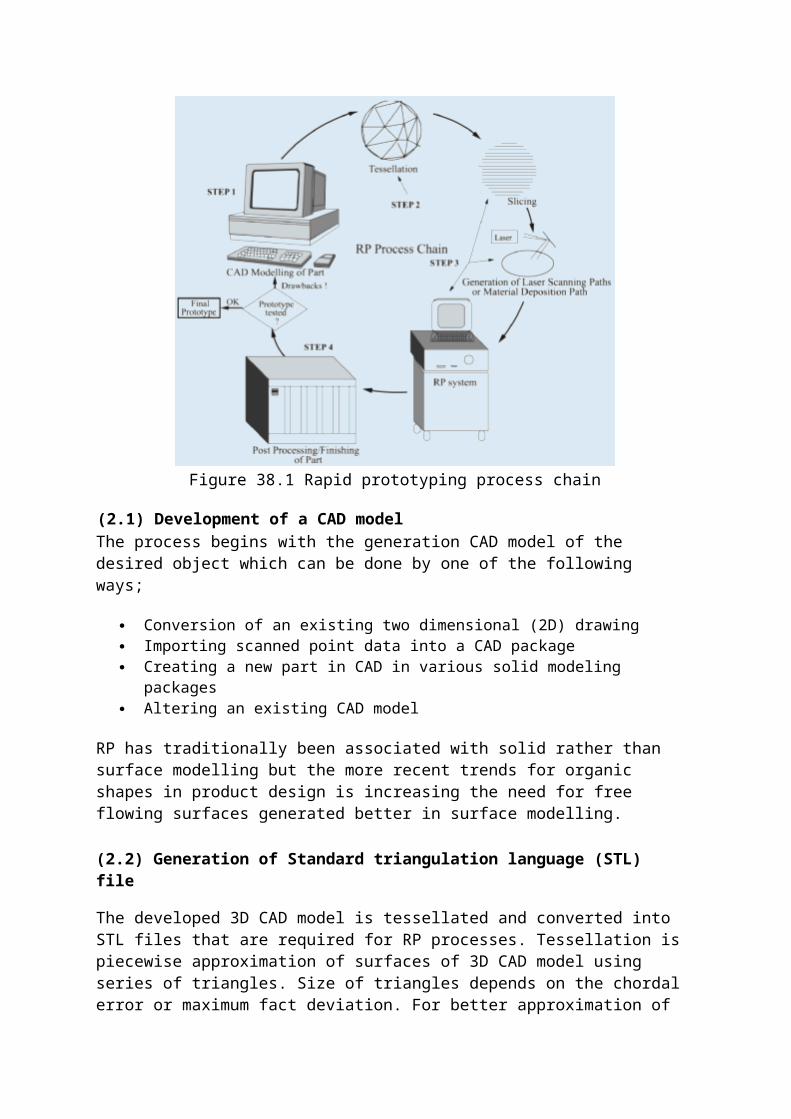
Figure 38.1 Rapid prototyping process chain
(2.1) Development of a CAD modelThe process begins with the generation CAD model of the desired object which can be done by one of the following ways;
Conversion of an existing two dimensional (2D) drawing Importing scanned point data into a CAD package Creating a new part in CAD in various solid modeling packages Altering an existing CAD model
RP has traditionally been associated with solid rather than surface modelling but the more recent trends for organic shapes in product design is increasing the need for free flowing surfaces generated better in surface modelling.
(2.2) Generation of Standard triangulation language (STL) file
The developed 3D CAD model is tessellated and converted into STL files that are required for RP processes. Tessellation is piecewise approximation of surfaces of 3D CAD model using series of triangles. Size of triangles depends on the chordal error or maximum fact deviation. For better approximation of surface and smaller chordal error, small size triangle are used which increase the STL file size. This tessellated CAD data generally carry defects like gaps, overlaps, degenerate facets etc which may necessitate the repair software. These defects are shown in figure below. The STL file connects the surface of the model in an array of triangles and consists of the X, Y and Z coordinates of the three vertices of each surface triangle, as well as an index that describes the orientation of the surface normal.
Figure 38.2 Tessellation defects
(2.3) Slicing the STL file

Slicing is defined as the creating contours of sections of the geometry at various heights in the multiples of layer thickness. Once the STL file has been generated from the original CAD data the next step is to slice the object to create a slice file (SLI). This necessitates the decision regarding part deposition orientation and then the tessellated model is sliced. Part orientation will be showing considerable effect on the surface as shown in the figures.
Figure 38.3 Effect of Part deposition Orientation
The thickness of slices is governed by layer thickness that the machine will be building in, the thicker the layer the larger the steps on the surface of the model when it has been built. After the STL file has been sliced to create the SLI files they are merged into a final build file. This information is saved in standard formats like SLC or CLI (Common Layer Interface) etc.

(2.4) Support Structures
As the parts are going to be built in layers, and there may be areas that could float away or of overhang which could distort. Therefore, some processes require a base and support structures to be added to the file which are built as part of the model and later removed.
(2.5) Manufacturing
As discussed previously, the RP process is additive i.e. it builds the parts up in layers of material from the bottom. Each layer is automatically bonded to the layer below and the process is repeated until the part is built. This process of bonding is undertaken in different ways for the various materials that are being used but
includes the use of Ultraviolet (UV) lasers, Carbon Dioxide lasers, heat sensitive glues and melting the material itself etc.
(2.6) Post processing
The parts are removed from the machine and post processing operations are performed sometimes to add extra strength to the part by filling process voids or finish the curing of a part or to hand finish the parts to the desired level. The level of post processing will depend greatly on the final requirements of the parts produced, for example, metal tooling for injection molding will require extensive finishing to eject the parts but a prototype part manufactured to see if it will physically fit in a space will require little or no post processing.
(3) Various RP Processes
Several RP techniques are being developed and commercially available. The first commercial process, StereoLithography (SL), came to the market in 1987. Nowadays, more than 30 different processes (not all commercialized) with high

accuracy and a large choice of materials exist. These processes can be classified in different ways but the most popular way is according to the form of material used as an input. This can be given as follows;
Liquid based processes
(i) Solidification of a liquid polymer(ii)Solidification of an electro-stat fluid(iii)Solidification of molten material
Discrete Particle based processes
(i) Fusing of particles by laser(ii)Joining particles by binder
Solid Sheets based process
(i) Bonding of sheets with adhesive(ii) Bonding of sheets with light
Some of the commercially popular RP processes are described below;
(3.1) Stereolithograpy
StereoLithography (SL) is the best known rapid prototyping system. The technique builds three-dimensional models from liquid photosensitive polymers that solidify when exposed to laser beam. The model is built upon a platform in a vat of photo sensitive liquid. A focused UV laser traces out the first layer, solidifying the model cross section while leaving excess areas liquid. In the next step, an elevator lowers the platform into the liquid polymer by an amount equal to layer thickness. A sweeper recoats the solidified layer with liquid, and the laser traces the second layer on the first. This process is repeated until the prototype is complete. Afterwards, the solid part is removed from the vat and rinsed clean of excess liquid. Supports are broken off and the model is then placed in an ultraviolet oven for complete curing.

Figure 38.5 Stereolithography
Application Range
Processing large variety of photo-sensitive polymers including clear, water resistant and flexible resins
Functional parts for tests Tools for pre series production tests. Manufacturing of medical models Manufacturing of electro-forms for Electro Discharge Machining (EDM) Form-fit functions for assembly tests.
Advantages
Possibility of manufacturing parts which are impossible to produce conventionally using a single process.
Continuous unattended operation for 24 hours. High resolution. Any geometrical shape can be made with virtually no limitation.
Disadvantages
Necessity to have support structures Accuracy not in the range of mechanical part manufacturing. Restricted areas of application due to given material properties. Labour requirements for post processing, especially cleaning.

(3.2) Selective Laser Sintering
Selective Laser Sintering (SLS) is a 3-dimensional printing process based on sintering, using a laser beam directed by a computer onto the surface of metallic or non-metallic powders selectively to produce copies of solid or surface models. The process operates on the layer-by-layer principle. At the beginning a very thin layer of heat fusible powder is deposited in the working space container. The -laser sinters the powders. The sintering process uses the laser to raise the temperature of the powder to a point of fusing without actually melting it. As the process is repeated, layers of powder are deposited and sintered until the object is complete. The powder is transferred from the powder cartridge feeding system to the part cylinder (the working space container) via a counter rolling cylinder, a scraper blade or a slot feeder. In the unsintered areas, powder remains loose and serves as natural support for the next layer of powder and object under fabrication. No additional support structure is required.
Figure 38.6 Selective Laser Sintering (SLS)
Application Range
Visual representation models. Functional and tough prototypes. Cast metal parts (by use of wax). Short run and soft tooling.
Advantages
Virtually any materials that have decreased viscosity upon heating can potentially be used.
Do not require any post-curing except when ceramics are used. No need to create a support structure, which saves time Advanced softwares allowing concurrent slicing of the part geometry files
while processing the object
Disadvantages
Raw appearance on the part surface due to hardening of additional powder on the borderline of the object
Necessity to provide the process chamber continuously with nitrogen to assure safe material sintering
Careful handling of toxic gases emitted from the fusing process
(3.3) Laminated Object manufacturing (LOM)
In this technique, layers of adhesive-coated sheet material are bonded together to form a prototype. The original material consists of paper laminated with heat-activated glue and rolled up on spools. A feeder/collector mechanism advances the sheet over the build platform, where a base has been constructed from paper and double-sided foam tape. In the next stage, a heated roller applies pressure to bond the paper to the base. A focused laser cuts the outline of the first layer into the paper and then cross-hatches the excess area (the negative space in the prototype). Cross-hatching breaks up the extra material, making it easier to remove during post-processing. During the build, the excess material provides excellent support for overhangs and thin-walled sections. After the first layer is cut, the platform lowers out of the way and fresh material is advanced. The platform rises slightly below the previous height, the roller bonds the second layer to the first, and the laser cuts the second layer. This process is repeated as needed to build the part, which will have a wood-like texture. Because the models are made of paper, they must be sealed and finished with paint or varnish to prevent moisture damage.

Figure 38.7 Laminated Object Manufacturing (LOM)
Application Range
Considering the specified of the procedure, the main application range is the working area of conceptual design.
Used for large bulky models as sand casting patterns.
Advantages
Variety of organic and inorganic materials can be used such as paper, plastic, ceramic, composite, etc. Relatively low costs
Much faster process than competitive techniques Virtually produces no internal stress and associated undesirable
deformation. Robust capacity of dealing with imperfect STL files, created with
discontinuities, Best suited for building large parts, as if the machine with the largest
workspace on the market today.
Disadvantages
Limited stability of the objects due to the bonding strength of the glued layers.
Not well suited for manufacturing parts with thin walls in the z-direction

Hollow parts, like bottles, can not be built.
(3.4) Fusion Deposition Modeling (FDM)
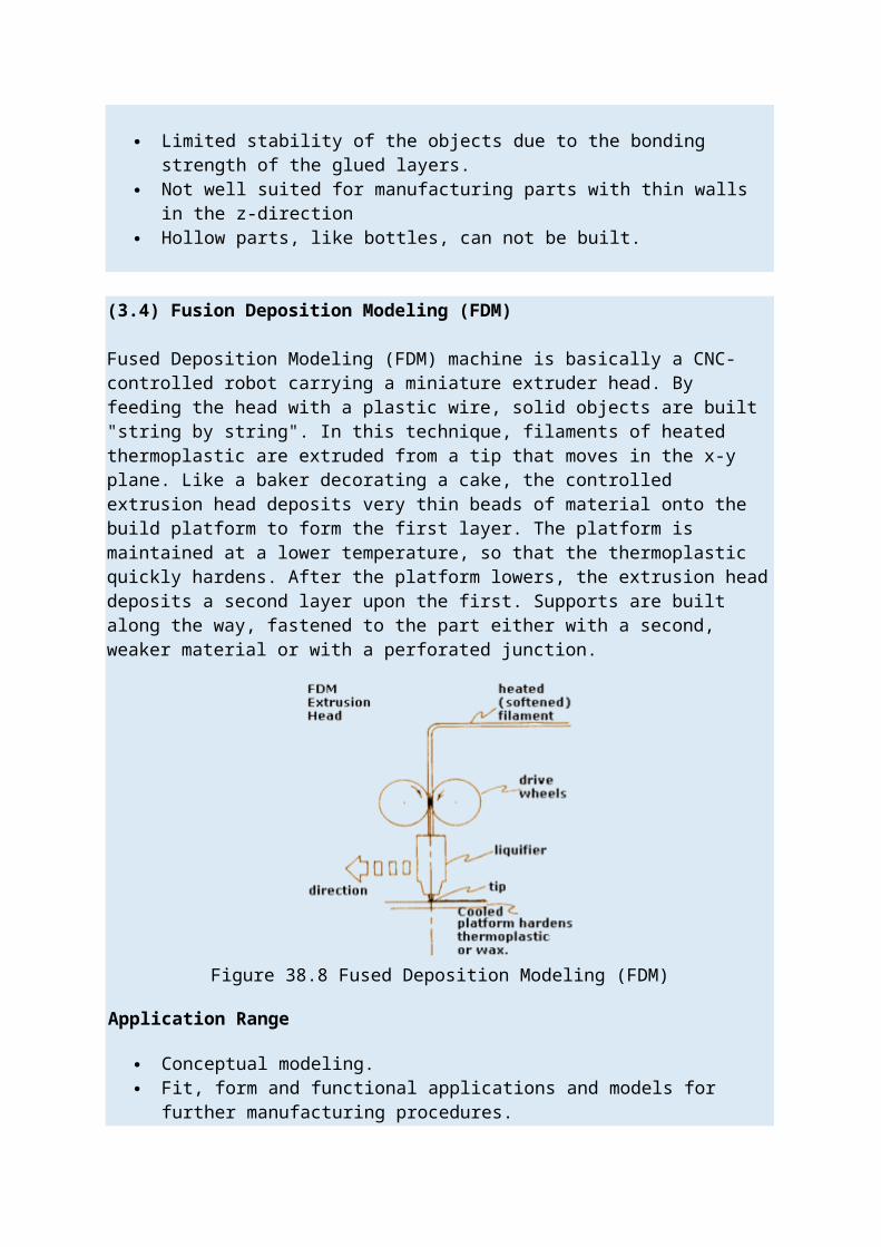
Fused Deposition Modeling (FDM) machine is basically a CNC-controlled robot carrying a miniature extruder head. By feeding the head with a plastic wire, solid objects are built "string by string". In this technique, filaments of heated thermoplastic are extruded from a tip that moves in the x-y plane. Like a baker decorating a cake, the controlled extrusion head deposits very thin beads of material onto the build platform to form the first layer. The platform is maintained at a lower temperature, so that the thermoplastic quickly hardens. After the platform lowers, the extrusion head deposits a second layer upon the first. Supports are built along the way, fastened to the part either with a second, weaker material or with a perforated junction.
Figure 38.8 Fused Deposition Modeling (FDM)
Application Range
Conceptual modeling. Fit, form and functional applications and models for further manufacturing
procedures. Investment casting and injection molding.
Advantages
Quick and cheap generation of models. Easy and convenient date building. No worry of possible exposure to toxic chemicals, lasers, or a liquid polymer
bath. No wastage of material during or after producing the model No requirement of clean-up. Quick change of materials

Disadvantages
Restricted accuracy due to the shape of the material used: wire of 1.27 mm diameter.
(3.5) Solid Ground Curing
Solid ground curing (SGC) is almost similar to stereolithography (SLA). In both one uses ultraviolet light to selectively harden photosensitive polymers. Unlike SLA, SGC cures an entire layer at a time. First, photosensitive resin is sprayed on the build platform. Secondly, the machine develops a photomask (like a stencil) of the layer to be built. This photomask is printed on a glass plate above the build platform using an electrostatic process similar to that found in photocopiers. The mask is then exposed to UV light, which only passes through the transparent portions of the mask to selectively harden the shape of the current layer. After the layer is cured, the machine vacuums up the excess liquid resin and sprays wax in its place to support the model during the build. The top surface is milled flat, and then the process repeats to build the next layer. When the part is complete, it must be de-waxed by immersing it in a solvent bath.
Figure 38.9 Solid Ground Curing (SGC)
Advantages
Large parts, 500 × 500 × 350 mm, can be fabricated quickly. High speed allows production-like fabrication of many parts or large parts. Masks are created with laser printing-like process, then full layer exposed at
once. No post-cure required. Milling step ensures flatness for subsequent layer. Wax supports model: no extra supports needed.
Disadvantages
Creates a lot of waste. Not as prevalent as SLA and SLS, but gaining ground because of the high
throughput and large parts
(3.6) 3D Printing
3D printing is very reminiscent of SLS, except that the laser is replaced by an inkjet head. The multi-channel jetting head (A) deposits a liquid adhesive compound onto the top layer of a bed of powder object material (B). The particles of the powder become bonded in the areas where the adhesive is deposited.
Once a layer is completed the piston (C) moves down by the thickness of a layer. As in SLS, the powder supply system (E) is similar in function to the build cylinder In this case the piston moves upward incrementally to supply powder for the process and the roller (D) spreads and compresses the powder on the top of the build cylinder. The process is repeated until the entire object is completed within the powder bed.
After completion the object is elevated and the extra powder brushed away leaving a "green" object. Parts must usually be infiltrated with a hardener before they can be handled without much risk of damage.
Figure 38.10 3D PrintingSurfaces of the parts produced by layer manufacturing processes suffer from poor surface finish and this is due to the inherent characteristics of the process itself like stair stepping effect, shrinkage etc. Least build time in RP is generally preferred but

stair stepping effect and poor surface finish restricts it. This has been induced on to the surface of the parts during the various stages that a particular part has to come across during a RP cycle, typically data preparation stage, part orientation, part geometry, deciding layer thickness etc. Figure 38.4 shows these effects on RP product.
(4) Some issues in RP
Because of layer by layer deposition of the material and due to the finite thickness of each layer, situation similar to stair case will be resulting on the surface and this effect is known as stair stepping effect. From the figures it can be seen that layer thickness will directly affect the maximum cusp height attained and the stair case effect on the surface.
Figure 38.11 Staircase effect in RP Parts
Figure 38.12 Effect of layer thickness on stair stepping effect

To reduce the surface roughness, one may go with very fine layers, but this will be increasing the overall build time and build cost considerably. If we choose maximum allowable layer thickness then, this will be generating a part with high surface roughness. So an optimum layer thickness must be decided. The solution for this is to go for adaptive slicing or local adaptive slicing.
Adaptive slicing is slicing the entire part with different thicknesses according to the local surface geometry and maximum cusp height that can be reached as shown in the figure above. In local adaptive slicing, maximum layer thickness will be considered and then checked for maximum slice thickness and each layer is further divided accordingly if required.