rapid prototyping energy management system for … prototyping consists of process such as system...
TRANSCRIPT

INTRODUCTIONThe concern of the depletion of crude oil is forcing
researchers around the world to explore new technologies toreplace fossil fuel as the main transportation energy source.In addition, more stringent global emission regulations, aswell as the green energy theme have pushed the automotiveindustry to adopt alternative energy technologies. Althoughthe development of batteries are leaping forward to in the pastdecades, aiming to serve as the main vehicle powertrainenergy source, the prices of batteries are still not low enoughto replace the conventional internal combustion engine. As aresult, popularity of hybrid electric vehicles has increased tofill the gap toward the future full vehicle electrification [1].
Multiple energy sources in the hybrid electric vehicles,however, inevitably introduce more complex control issuessuch as energy distribution and drivability. Facing theincreased complexity, model-based rapid control prototypinghas become a standard method for the development andoptimization of HEV control applications [2]. The rapid
control prototyping consists of process such as systemmodeling, control algorithm synthesis, simulation analysisand vehicle implementation. With auto-code generation, thecontrol algorithm is implemented using graphical languageinstead of manual programming [3, 4]. The high-levelprogramming environment allows researchers to developcomplicated and computation-intensive control models andoptimize control algorithms as often as needed. The modularcharacteristics of the controllers facilitate the scalability andthe flexibility of control design.
With the hardware-in-the-loop test facilities, the designand test process of powertrain components can be modulized[5, 6, 7]. dSPACE HIL system has Automotive SimulationModel (ASM) to serve as the physical simulation model toprovide necessary information for the real time vehiclecontrol. Simulated sensor signals are generated by the I/Oboards and outputted to the testing controllers [8, 9, 10]. Thecontrol signals from the controllers can also be captured bythe simulator to actuate plant model. In this paper, theperformance of the hybrid ECU and low-level ECUs for a
2013-01-0155Published 04/08/2013
Copyright © 2013 SAE Internationaldoi:10.4271/2013-01-0155saealtpow.saejournals.org
Rapid Prototyping Energy Management System for a SingleShaft Parallel Hybrid Electric Vehicle Using Hardware-in-the-
Loop SimulationYang Li, Pushkar Agashe, Zicheng Ge and Bo Chen
Michigan Technological Univ.
ABSTRACTEnergy management is one of the key challenges for the development of Hybrid Electric Vehicle (HEV) due to its
complex powertrain structure. Hardware-In-the-Loop (HIL) simulation provides an open software architecture whichenables rapid prototyping HEV energy management system. This paper presents the investigation of the energymanagement system for a single shaft parallel hybrid electric vehicle using dSPACE eDrive HIL system. The parallelhybrid electric vehicle, energy management system, and low-level Electronic Control Unit (ECU) were modeled usingdSPACE Automotive Simulation Models and dSPACE blocksets. Vehicle energy management is achieved by a vehicle-level controller called hybrid ECU, which controls vehicle operation mode and torque distribution among InternalCombustion Engine (ICE) and electric motor. The individual powertrain components such as ICE, electric motor, andtransmission are controlled by low-level ECUs. To examine the performance of hybrid ECU and low-level ECUs, vehiclemode control, speed tracking, energy distribution, regenerative braking, and engine operating region were investigated inthe HIL environment with a hardware electric motor controller consisting of dSPACE MicroAutoBox II and the AC MotorControl Solution. The presented work illustrates that the HIL system is a suitable environment for the rapid prototyping ofHEV control strategies.
CITATION: Li, Y., Agashe, P., Ge, Z. and Chen, B., "Rapid Prototyping Energy Management System for a Single ShaftParallel Hybrid Electric Vehicle Using Hardware-in-the-Loop Simulation," SAE Int. J. Alt. Power. 2(2):2013, doi:10.4271/2013-01-0155.
____________________________________
241
THIS DOCUMENT IS PROTECTED BY U.S. AND INTERNATIONAL COPYRIGHTIt may not be reproduced, stored in a retrieval system, distributed or transmitted, in whole or in part, in any form or by any means.
Downloaded from SAE International by Brought to by the J. Robert Van Pelt Library / Michigan Technological Univ. , Tuesday, July 09, 2013 12:23:38 AM

parallel HEV was evaluated by examining the vehicleperformance using a dSPACE HIL system.
The rest of the paper is organized as follows. Section 2introduces the powertrain and control architecture of a singleshaft parallel HEV. Section 3 discusses vehicle operationmodes and energy management strategies in hybrid ECU.Section 4 presents the low-level ECUs, including engineECU, motor ECU, and transmission ECU. Section 5 giveshardware-in-the-loop simulation and HIL simulation setup.Section 6 describes the HIL evaluation results of hybrid ECUand low-level ECUs. Section 7 concludes the presented work.
OVERVIEW OF SINGLE SHAFTPARALLEL HEV POWERTRAIN AND
CONTROL SYSTEMARCHITECTURE
The configuration of the single shaft parallel HEVpowertrain is shown in Figure 1. Tractive power can beprovided by either a gasoline Internal Combustion Engine(ICE), a Permanent Magnet Synchronous Motor (PMSM), orboth of them. The PMSM can operate as a generator tocharge battery using the energy from ICE or regenerativebraking. A Li-ion battery pack provides and absorbs electricalenergy to and from PMSM through DC/AC and AC/DCconverters. The ICE, PMSM and gearbox are coupledthrough a single shaft which contains two clutches to connector disconnect powertrain components. Clutch 1 between theICE and PMSM is used for coupling or decoupling the ICE.Clutch 2 and the gearbox form an automatic transmission.The tractive power is delivered to the wheels through thefinal drive located after the automatic transmission. Thespecifications for the ICE, PMSM, battery and transmissionare listed in Table 1.
Figure 1. Single shaft parallel HEV powertrain.
Table 1. Specifications of powertrain components.
The control architecture of the single shaft parallel HEVis shown in Figure 2. The control system consists of a hybridECU, an engine ECU, a motor ECU, a transmission ECU,and a battery management system. The hybrid ECUoptimizes powertrain energy consumption E, which isaffected by the following factors:
(1)
Hybrid ECU determines RTrq, Rb, Rgear, KeyICE, andKeyclutch based on current vehicle working conditions, suchas Treq, v and SOC.
Figure 2. The ECU network of single shaft parallelHEV.
Li et al / SAE Int. J. Alt. Power. / Volume 2, Issue 2(July 2013)242
THIS DOCUMENT IS PROTECTED BY U.S. AND INTERNATIONAL COPYRIGHTIt may not be reproduced, stored in a retrieval system, distributed or transmitted, in whole or in part, in any form or by any means.
Downloaded from SAE International by Brought to by the J. Robert Van Pelt Library / Michigan Technological Univ. , Tuesday, July 09, 2013 12:23:38 AM

Based on the commands from the hybrid ECU, low-levelECUs control individual powertrain components to fulfillspecified performance. For example, engine ECU adjuststhrottle position, injection timing and spark timing based onthe torque request from the hybrid ECU and current engineworking conditions. It can start and stop engine or keepengine running at idle state. The motor ECU controls thePMSM either as a tractive motor or a generator according tothe commands from the hybrid ECU. The output power of themotor is controlled by the motor ECU through PWM outputsignals to the inverter board. The transmission ECU executesshifting logic of the gearbox and determines the open andclose of two clutches.
VEHICLE OPERATION MODES ANDENERGY MANAGEMENT
STRATEGY IN HYBRID ECUThe single shaft parallel HEV has five operation modes as
shown in Figure 3. Figure 3 (a) shows the electric only modein which the PMSM is the only power source of HEV. Sincea PMSM has a higher energy efficiency comparing with anICE, PMSM is used whenever its maximum torque outputsatisfies powertrain torque demand while battery State OfCharge (SOC) is within a reasonable range. In the electriconly mode, the ICE is turned off and disconnected from theoutput shaft. If the driver's power request is beyond thecapability of the PMSM or the SOC of the battery is out of adesired range, the ICE will be turned on and connected to theoutput shaft as shown in Figure 3 (b), (c) and (d). Figure 3 (b)is the battery charging mode in which the ICE chargesbattery and provides tractive power simultaneously. ThePMSM operates as a generator in the battery charging modeto convert mechanical energy to electrical energy forcharging battery. In engine only model as shown in Figure 3(c), the ICE is the only power source of the vehicle. Figure 3(d) shows the hybrid mode in which both ICE and PMSMoutput power to HEV powertrain. PMSM outputs maximumtorque if vehicle torque request is greater than the sum of theoptimal engine torque and the maximum electric motortorque. Otherwise, it outputs the torque difference betweenvehicle torque request and optimal engine torque. In this case,the ICE outputs optimal torque to achieve best fuel economy.Figure 3 (e) shows the regenerative braking mode. Whenvehicle is decelerating, PMSM works as a generator torecover vehicle kinetic energy. In regenerative braking mode,the clutch between ICE and PMSM is open and the engine isdisconnected from the output shaft.
Figure 3. Vehicle operation modes and powertrainenergy flow. (a) Electric only mode. (b) Battery charging
mode. (c) Engine only model. (d) Hybrid mode. (e)Regenerative braking mode.
The hybrid ECU controls the overall energy flow amongindividual powertrain components. It optimizes the energyconsumption of the entire powertrain while maintaining adesired vehicle performance. The hybrid ECU determines thetorque demands for individual powertrain components basedon driver's demand, optimum traction, efficiency, batterycharge status, comfort and thermal conditions. The batterySOC is also maintained within a desired range throughoperating the electric motor as a generator recovering energyfrom regenerative braking or engine charging. Figure 4 showsthe vehicle-level hybrid ECU which controls vehicleoperation mode and torque distribution. The hybrid ECUmodel is modified based on the hybrid ECU provided bydSPACE. In the hybrid ECU model, the Accelerator PedalPosition (APP) and Brake Pedal Position (BPP) determine ifthe vehicle runs in traction or regenerative braking mode. Intraction condition, the electric only mode is a default vehicleoperating mode. However, the engine will be turned on ifvehicle torque request is greater than the maximum motortorque or the battery SOC is insufficient to drive the motor.When the gasoline engine is turned on, the hybrid ECU letsthe gasoline engine work at an optimal torque as often aspossible. If the torque request is greater than the engineoptimal torque and the SOC is greater than its minimumvalue, the motor is turned on for traction and vehicle works inhybrid mode. The motor provides the extra torque requestbeyond the engine optimal torque. If powertrain torquerequest is smaller than the engine optimal torque and batterySOC is less than its maximum value, the motor will work as agenerator to allow the engine working in the optimal rangeand the vehicle is in battery charging mode. The thirdworking mode of ICE is engine only mode. In this workingmode, engine is the only tractive power source of the vehicle.
Li et al / SAE Int. J. Alt. Power. / Volume 2, Issue 2(July 2013) 243
THIS DOCUMENT IS PROTECTED BY U.S. AND INTERNATIONAL COPYRIGHTIt may not be reproduced, stored in a retrieval system, distributed or transmitted, in whole or in part, in any form or by any means.
Downloaded from SAE International by Brought to by the J. Robert Van Pelt Library / Michigan Technological Univ. , Tuesday, July 09, 2013 12:23:38 AM

LOW-LEVEL ECU FUNCTIONALITYdSPACE blockset libraries provide low-level soft ECU
(softECU) for the control of engine, motor, or transmission.This section introduces the functionalities of these softECUs.
Engine ECUEngine control is one of the major control tasks of hybrid
electric vehicles. For the HIL simulation, either a softECU orhardware ECU can be used. The dSPACE engine softECUconsists of five functional blocks, engine torque calculation,relative air mass calculation, rail pressure control,combustion calculation, and airpath control, as shown inFigure 5. The engine softECU simulates a real ECU to read inengine operational signals such as engine speed and intakemanifold pressure, as well as the environmental signals suchas temperature and pressure along with the engine torquedemand signal. These sensor signals are calculated based onAutomotive Simulation Model, a physical model developedby dSPACE company. The engine torque demand isdetermined by the hybrid ECU. Having known the enginetorque demand and real-time engine operating conditionsfrom sensor signals, the engine softECU calculates theignition timing, injection duration and throttle position basedon the rule-based control algorithm in the combustioncalculation block. In addition to combustion calculation, theairpath related control tasks and rail pressure control, mainlydetermining and maintaining the set EGR level, turbopressure setpoint, and rail pressure, are implemented in thissoftECU. Users could access to some critical parametersrelated to EGR, turbocharger and rail pressure control such asthe maximum EGR valve flow area and the fuel system highpressure pump volume.
Figure 5. The block diagram of engine ECU.
Motor ECUMotor ECU controls motor output torque and speed based
on torque request from hybrid ECU and desired vehiclespeed. The cascade control architecture is adopted in themotor ECU as shown in Figure 6. The inner loop is current/torque loop and the outer loop is speed loop. The current forthe PMSM motor are regulated in the dq reference frame. Theq -axis current command is generated by the outer loop speedcontroller and the d -axis current command is set to zero. Thecurrent feedback signals from three-phase motor coils, I a, I band I c, are transformed to dq axes using equation (2). Withthe current feedback information, the dq current commandsare converted into dq voltage commands. The dq voltagecommands are then transformed into abc reference frame forthe motor ECU to generate three phase high side and low sidePulse Width Modulated (PWM) signals based on the inverterDC bus voltage. The PWM signals are used to control theswitches on the each half bridge of inverter to control the
Figure 4. Vehicle operation mode control and transition conditions.
Li et al / SAE Int. J. Alt. Power. / Volume 2, Issue 2(July 2013)244
THIS DOCUMENT IS PROTECTED BY U.S. AND INTERNATIONAL COPYRIGHTIt may not be reproduced, stored in a retrieval system, distributed or transmitted, in whole or in part, in any form or by any means.
Downloaded from SAE International by Brought to by the J. Robert Van Pelt Library / Michigan Technological Univ. , Tuesday, July 09, 2013 12:23:38 AM
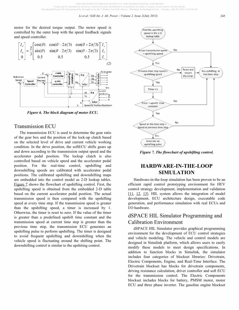
motor for the desired torque output. The motor speed iscontrolled by the outer loop with the speed feedback signalsand speed controller.
(2)
Figure 6. The block diagram of motor ECU.
Transmission ECUThe transmission ECU is used to determine the gear ratio
of the gear box and the position of the lock-up clutch basedon the selected level of drive and current vehicle workingcondition. In the drive position, the softECU shifts gears upand down according to the transmission output speed and theaccelerator pedal position. The lockup clutch is alsocontrolled based on vehicle speed and the accelerator pedalposition. For the real-time control, upshifting anddownshifting speeds are calibrated with accelerator pedalpositions. The calibrated upshifting and downshifting mapsare embedded into the control model as 2-D lookup tables.Figure 7 shows the flowchart of upshifting control. First, theupshifting speed is obtained from the embedded 2-D tablebased on the current accelerator pedal position. The actualtransmission speed is then compared with the upshiftingspeed at every time step. If the transmission speed is greaterthan the upshifting speed, a timer is increased by 1.Otherwise, the timer is reset to zero. If the value of the timeris greater than a predefined upshift time constant and thetransmission speed at current time step is greater than theprevious time step, the transmission ECU generates anupshifting pulse to perform upshifting. The timer is designedto avoid frequent upshifting and downshifting when thevehicle speed is fluctuating around the shifting point. Thedownshifting control is similar to the upshiting control.
Figure 7. The flowchart of upshifting control.
HARDWARE-IN-THE-LOOPSIMULATION
Hardware-in-the-loop simulation has been proven to be anefficient rapid control prototyping environment for HEVcontrol strategy development, implementation and validation[11, 12, 13]. HIL system allows the integration of modeldevelopment, ECU architecture design, executable codegeneration, and performance simulation with real ECUs andI/O hardware.
dSPACE HIL Simulator Programming andCalibration Environment
dSPACE HIL Simulator provides graphical programmingenvironment for the development of ECU control strategiesand vehicle modeling. The vehicle and control models aredesigned in Simulink platform, which allows users to easilymodify these models to meet design specifications. Inaddition to function blocks in Simulink, the simulatorincludes four categories of blockset libraries: Drivetrain,Electric Components, Engine, and Real-Time Interface. TheDrivetrain blockset has blocks for drivetrain components,driving resistance calculation, driver controller and soft ECUfor the transmission control. The Electric Componentsblockset includes blocks for battery, PMSM motor, motorECU and three phase inverter. The gasoline engine blockset
Li et al / SAE Int. J. Alt. Power. / Volume 2, Issue 2(July 2013) 245
THIS DOCUMENT IS PROTECTED BY U.S. AND INTERNATIONAL COPYRIGHTIt may not be reproduced, stored in a retrieval system, distributed or transmitted, in whole or in part, in any form or by any means.
Downloaded from SAE International by Brought to by the J. Robert Van Pelt Library / Michigan Technological Univ. , Tuesday, July 09, 2013 12:23:38 AM

provides components for the gasoline engine modeling. Theblocks can be broadly divided into fuel system, air handling,combustion, emission and soft engine ECU. The real-timeinterface (RTI) blockset provides function blocks to associateSimulink models with real hardware, including processorboards and I/O boards. The function blocks can generateinterrupter signals, define real-time sensor signals and captureactuation signals.
The simulator is meant to conduct HIL testing butsimulations can be run using softECUs if hardware ECUs arenot available. For example, a soft engine ECU can be usedfor the engine control of spark, fuel injection, throttle and fuelmetering. In the event of a real ECU being used, the softECUblock can be removed and signals from the hardware ECUreplace the outputs from the softECU. Once vehicle andcontrol models are completed, Matlab Embedded Coder willbe used for auto code generation to generate C code. Autocode generation makes modifying the models much simplerand time effective. The hassle with low-level coding iscompletely eliminated and allows users with a basicunderstanding of Simulink to work on embedded controlsystem design.
Before performing simulation, the model is parameterizedby the dSPACE Model Desk software. The Model Desksoftware provides a common platform for parameterizing allthe subsystems used in the vehicle model. Parameters of allthe subsystems can be defined using this software. To run thesame model with a different set of parameters, parameter setsare saved. These parameter sets are then downloaded to themodel before compiling it. The compiled models are thenflashed to the simulator.
The real-time simulation is running in dSPACE ControlDesk Next Generation (Control Desk NG). This softwareallows systematic configuration of simulation runs. Figure 8shows the cockpit layout of the real-time vehicle simulationfor setting up important parameters such as gear ratio, throttleposition, steering angle, and so on. The simulation results,such as longitudinal position, parallel position, vehicle speed,acceleration pedal, brake pedal, and engine torque, can bedisplayed and plotted through the instruments in the layout.The operating condition of the vehicle is updated in real-timebased on the input drive cycle, which allows the observationof the transient response of the vehicle performance ratherthan steady state. The simulation results can also be loggedusing recorders. These recorders are triggered off signals tolook at signals during specific portions of the drive cycles.Predefined start and stop criterion ensures precise recordingof the required portions of the drive cycle. Recorded data canbe exported to Matlab for further analysis.
Figure 8. dSPACE HIL simulation environment -Control Desk NG.
HIL Simulation SetupFigure 9 shows the HIL simulation setup and primary
signals of the HIL system for the investigation of a singleshaft parallel HEV energy management system. The vehicleplant is modeled using dSPACE Automotive SimulationModel. The hybrid ECU, engine ECU and transmission ECU,are soft ECUs and integrated with the vehicle model. Themotor ECU is a hardware ECU implemented byMicroAutoBox II. The simulator outputs sensor signals andmotor torque request to the motor ECU and capturesactuation signals from MicroAutoBox II.
VEHICLE PERFORMANCEEVALUATION WITH HIL
SIMULATIONTo examine the performance of hybrid ECU and low-
level ECUs, vehicle mode control, speed tracking, energy/power distribution, regenerative braking and engine operatingregion, for specified drive cycles were investigated using HILtest. The selected drive cycles were Urban DynamometerDriving Schedule (UDDS) and a high acceleration aggressivedriving schedule (US06) drive cycles.
Vehicle Mode Control and Speed TrackingFigure 10 shows the UDDS drive cycle and vehicle mode
at different time instants. To represent five vehicle modes, avehicle mode variable is designed in the simulation. Thevalue of this variable is defined as: 0 - battery charging mode,1 - engine only mode, 2 -hybrid mode, 3 - electric only mode,and 4 - regenerative braking mode. The simulation shows that
Li et al / SAE Int. J. Alt. Power. / Volume 2, Issue 2(July 2013)246
THIS DOCUMENT IS PROTECTED BY U.S. AND INTERNATIONAL COPYRIGHTIt may not be reproduced, stored in a retrieval system, distributed or transmitted, in whole or in part, in any form or by any means.
Downloaded from SAE International by Brought to by the J. Robert Van Pelt Library / Michigan Technological Univ. , Tuesday, July 09, 2013 12:23:38 AM
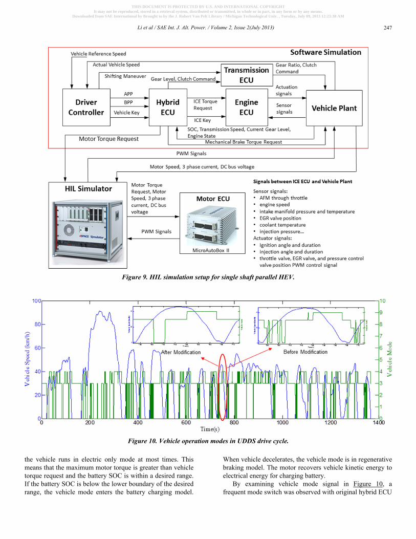
the vehicle runs in electric only mode at most times. Thismeans that the maximum motor torque is greater than vehicletorque request and the battery SOC is within a desired range.If the battery SOC is below the lower boundary of the desiredrange, the vehicle mode enters the battery charging model.
When vehicle decelerates, the vehicle mode is in regenerativebraking model. The motor recovers vehicle kinetic energy toelectrical energy for charging battery.
By examining vehicle mode signal in Figure 10, afrequent mode switch was observed with original hybrid ECU
Figure 9. HIL simulation setup for single shaft parallel HEV.
Figure 10. Vehicle operation modes in UDDS drive cycle.
Li et al / SAE Int. J. Alt. Power. / Volume 2, Issue 2(July 2013) 247
THIS DOCUMENT IS PROTECTED BY U.S. AND INTERNATIONAL COPYRIGHTIt may not be reproduced, stored in a retrieval system, distributed or transmitted, in whole or in part, in any form or by any means.
Downloaded from SAE International by Brought to by the J. Robert Van Pelt Library / Michigan Technological Univ. , Tuesday, July 09, 2013 12:23:38 AM

implementation. As shown in the right enlarged subfigure,some of vehicle mode only last for about 1 second. This willcause frequent turn on/off powertrain components and powerelectronics. To avoid frequent change of vehicle mode, thehybrid ECU was modified. With modified hybrid ECU, thevehicle mode changes only when the transition conditions aremet for a predefined consecutive number of time steps. Thecomparison of vehicle mode signal with original/modifiedhybrid ECU is shown in Figure 10 in two enlargedsubfigures. The modified hybrid ECU shows improvedvehicle mode control performance.
Figure 11 shows the speed tracking performance of thesingle shaft parallel HEV running on UDDS drive cycle. Ingeneral, vehicle speed tracks the reference speed well. Thelarge speed tracking error occurs during the coupling of ICEto the shaft. This is due to the current clutch 1 control is asimple open/close control (0 means close and 5 means open).The clutch 1 control algorithm will be further studied in thefuture work to reduce vibration and speed error during engineengagement.
Figure 11. Vehicle speed tracking.
Vehicle Power and Energy DistributionThe longitude vehicle dynamics can be described by
equation (3), where FT is the tractive force to propel thevehicle; Froll is the rolling resistance force; FAd is theaerodynamic drag force; and FGf is the gravitational force.The rolling resistance force, aerodynamic drag force, andgravitational force can be calculated by equations (4), (5), (6),where m is the total mass of the vehicle; g is the gravitationalacceleration constant; θ is the grade angle with respect to thehorizon; fr is the coefficient of rolling resistance; v is vehiclespeed; ρ is the air density; cd is the aerodynamic dragcoefficient; and A is the equivalent frontal area of the vehicle.If a vehicle runs on a flat road, the instantaneous powerrequest of the vehicle over a drive cycle can be calculated byequation (7) using vehicle speed profile.
(3)
(4)
(5)
(6)
(7)
Figure 12 shows the instantaneous vehicle power request,rolling resistance power, and wind drag power for the UDDSdrive cycle. The gravitational force FGf = 0 since the gradeangle θ = 0. The positive power request is for the vehicletraction and the negative power is braking power. Thetraction power can be divided into several parts, includingacceleration power, rolling resistance loss, and wind dragloss. The negative power is the braking energy which may berecovered by regenerative braking. Figure 13 illustrates thebreakdown of traction energy over a UDDS drive cycle. Thevalues of simulation parameters are listed in Table 2.
Li et al / SAE Int. J. Alt. Power. / Volume 2, Issue 2(July 2013)248
THIS DOCUMENT IS PROTECTED BY U.S. AND INTERNATIONAL COPYRIGHTIt may not be reproduced, stored in a retrieval system, distributed or transmitted, in whole or in part, in any form or by any means.
Downloaded from SAE International by Brought to by the J. Robert Van Pelt Library / Michigan Technological Univ. , Tuesday, July 09, 2013 12:23:38 AM

Figure 13. The breakdown of traction energy over aUDDS drive cycle.
Table 2. Simulation parameters.
Regenerative BrakingFor the regenerative braking control, the motor is
designed to recover as much braking energy as possible basedon its torque capacity and shaft speed. The regenerativebraking is disabled when the vehicle is lower than 0.1 km/hor the SOC value exceeds high charging threshold. When thebraking power is greater than the regenerative braking, theadditional amount is consumed in friction braking. Foraggressive drive cycles, only part of the braking power can berecovered. This is because the braking power sometimes isgreater than the maximum motor power. Figure 14 shows theinstantaneous braking power and regenerative braking powerrunning over US06 drive cycle. For US06 drive cycle, theenergy recovered in regenerative braking is 0.4638kWh and
friction braking energy is 0.1089kWh. The regenerativebraking recovered 81% of braking energy in US06 drivecycle.
Figure 14. Braking power in US06 drive cycle.
Engine on/off and Operating RegionDue to low energy efficiency of ICE, the time percentage
of engine operation in a drive cycle is an important indicationof vehicle fuel economy. In addition, the operating region ofthe ICE is crucial to the vehicle fuel consumption. With rapidprototyping system, it is easy to analyze the engine state andoperating range during a drive cycle and to designappropriate control strategies. Figure 15 shows the enginestate change during UDDS drive cycle. The Engine Statevariable indicates different engine working states, whosevalue is defined as: 0 - engine turned off, 1 - engine idling, 2 -only engine providing traction power, 3 - engine providingtraction power and charging battery, and 4 - engine providingtraction power with e-motor. For UDDS drive cycle, the ICEis turned on 30.8% of time. When ICE is on, approximately53.3% of time is at idling state. The engine idling state isdesigned to avoid quick engine on/off.
Figure 12. Vehicle power request, rolling resistance power, and wind drag power over a UDDS drive cycle.
Li et al / SAE Int. J. Alt. Power. / Volume 2, Issue 2(July 2013) 249
THIS DOCUMENT IS PROTECTED BY U.S. AND INTERNATIONAL COPYRIGHTIt may not be reproduced, stored in a retrieval system, distributed or transmitted, in whole or in part, in any form or by any means.
Downloaded from SAE International by Brought to by the J. Robert Van Pelt Library / Michigan Technological Univ. , Tuesday, July 09, 2013 12:23:38 AM
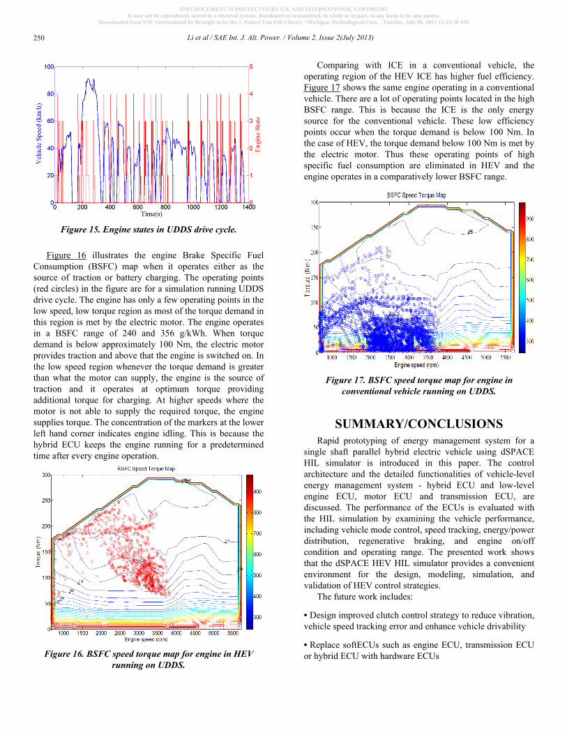
Figure 15. Engine states in UDDS drive cycle.
Figure 16 illustrates the engine Brake Specific FuelConsumption (BSFC) map when it operates either as thesource of traction or battery charging. The operating points(red circles) in the figure are for a simulation running UDDSdrive cycle. The engine has only a few operating points in thelow speed, low torque region as most of the torque demand inthis region is met by the electric motor. The engine operatesin a BSFC range of 240 and 356 g/kWh. When torquedemand is below approximately 100 Nm, the electric motorprovides traction and above that the engine is switched on. Inthe low speed region whenever the torque demand is greaterthan what the motor can supply, the engine is the source oftraction and it operates at optimum torque providingadditional torque for charging. At higher speeds where themotor is not able to supply the required torque, the enginesupplies torque. The concentration of the markers at the lowerleft hand corner indicates engine idling. This is because thehybrid ECU keeps the engine running for a predeterminedtime after every engine operation.
Figure 16. BSFC speed torque map for engine in HEVrunning on UDDS.
Comparing with ICE in a conventional vehicle, theoperating region of the HEV ICE has higher fuel efficiency.Figure 17 shows the same engine operating in a conventionalvehicle. There are a lot of operating points located in the highBSFC range. This is because the ICE is the only energysource for the conventional vehicle. These low efficiencypoints occur when the torque demand is below 100 Nm. Inthe case of HEV, the torque demand below 100 Nm is met bythe electric motor. Thus these operating points of highspecific fuel consumption are eliminated in HEV and theengine operates in a comparatively lower BSFC range.
Figure 17. BSFC speed torque map for engine inconventional vehicle running on UDDS.
SUMMARY/CONCLUSIONSRapid prototyping of energy management system for a
single shaft parallel hybrid electric vehicle using dSPACEHIL simulator is introduced in this paper. The controlarchitecture and the detailed functionalities of vehicle-levelenergy management system - hybrid ECU and low-levelengine ECU, motor ECU and transmission ECU, arediscussed. The performance of the ECUs is evaluated withthe HIL simulation by examining the vehicle performance,including vehicle mode control, speed tracking, energy/powerdistribution, regenerative braking, and engine on/offcondition and operating range. The presented work showsthat the dSPACE HEV HIL simulator provides a convenientenvironment for the design, modeling, simulation, andvalidation of HEV control strategies.
The future work includes:
• Design improved clutch control strategy to reduce vibration,vehicle speed tracking error and enhance vehicle drivability
• Replace softECUs such as engine ECU, transmission ECUor hybrid ECU with hardware ECUs
Li et al / SAE Int. J. Alt. Power. / Volume 2, Issue 2(July 2013)250
THIS DOCUMENT IS PROTECTED BY U.S. AND INTERNATIONAL COPYRIGHTIt may not be reproduced, stored in a retrieval system, distributed or transmitted, in whole or in part, in any form or by any means.
Downloaded from SAE International by Brought to by the J. Robert Van Pelt Library / Michigan Technological Univ. , Tuesday, July 09, 2013 12:23:38 AM
• Develop optimization-based HEV supervisory controlstrategies and compare the performance of these controlstrategies with rule-based control design.
REFERENCES1. Tate, E. D., Harpster, M. O., and Savagian, P. J., “The Electrification of
the Automobile: From Conventional Hybrid, to Plug-in Hybrids, toExtended-Range Electric Vehicles,” SAE Int. J. Passeng. Cars -Electron. Electr. Syst. 1(1):156-166, 2009, doi:10.4271/2008-01-0458.
2. Kott, K. and Waeltermann, P., “Embedded Software Tools EnableHybrid Vehicle Architecture Design and Optimization,” SAE TechnicalPaper 2010-01-2308, 2010, doi:10.4271/2010-01-2308.
3. Wagener, A., Kabza, H., Koerner, C., and Seger, P., “Model-basedDrivetrain Development and Rapid Prototyping For a Hybrid ElectricCar,” SAE Technical Paper 2001-01-3422, 2001, doi:10.4271/2001-01-3422.
4. Tsai, G., Wu, Y., Chen, B., and Chuang, H., “Rapid Prototyping ECU ofa SI Engine with Fuel Injection and Ignition Control,” SAE TechnicalPaper 2004-01-0419, 2004, doi:10.4271/2004-01-0419.
5. Fathy, H. K., Filipi, Z. S., Hagena, J., and Stein, J. L., “Review ofhardware-in-the-loop simulation and its prospects in the automotivearea,” Proc. SPIE 6228, Modeling and Simulation for MilitaryApplications 62280E-62280E, 2006, doi: 10.1117/12.667794.
6. Anakwa, W. K. N., Roca, H. P., Lopez, J., and Malinowski, A.,“Environments for rapid implementation of control algorithms andhardware-in-the-loop simulation,” in IECON 02 [Industrial ElectronicsSociety, IEEE 2002 28th Annual Conference]2002 3:2288-2293 vol.3,2002, doi: 10.1109/iecon.2002.1185329.
7. Wagener, A., Schulte, T., Waeltermann, P., and Schuette, H.,“Hardware-in-the-Loop Test Systems for Electric Motors in AdvancedPowertrain Applications,” SAE Technical Paper 2007-01-0498, 2007,doi:10.4271/2007-01-0498.
8. Köhl, S. and Jegminat, D., “How to Do Hardware-in-the-LoopSimulation Right,” SAE Technical Paper 2005-01-1657, 2005, doi:10.4271/2005-1-1657.
9. Ramaswamy, D., McGee, R., Sivashankar, S., Deshpande, A., Allen, J.,Rzemien, K., and Stuart, W., “A Case Study in Hardware-In-the-LoopTesting: Development of an ECU for a Hybrid Electric Vehicle,” SAETechnical Paper 2004-01-0303, 2004, doi:10.4271/2004-01-0303.
10. Dhaliwal, A., Nagaraj, S. C., and Ali, S., “Hardware-in-the-LoopSimulation for Hybrid Electric Vehicles - An Overview, LessonsLearned and Solutions Implemented,” SAE Technical Paper2009-01-0735, 2009, doi:10.4271/2009-01-0735.
11. Semenov, S. G., “Automation of Hardware-in-the-Loop and In-the-Vehicle Testing and Validation for Hybrid Electric Vehicles at Ford,”SAE Technical Paper 2006-01-1448, 2006, doi:10.4271/2006-01-1448.
12. Jiang, S., Smith, M. H., Kitchen, J., and Ogawa, A., “Development of anEngine-in-the-loop Vehicle Simulation System in Engine DynamometerTest Cell,” SAE Technical Paper 2009-01-1039, 2009, doi:10.4271/2009-01-1039.
13. Habeebullah, A., Zheng, Q., and Chung, W., “A Closed-Loop Drive-train Model for HIL Test Bench,” SAE Technical Paper 2009-01-1139,2009, doi:10.4271/2009-01-1139.
CONTACT INFORMATIONBo Chen, PhDAssistant ProfessorDepartment of Mechanical Engineering - EngineeringMechanicsDepartment of Electrical and Computer EngineeringMichigan Technological [email protected]://www.imes.mtu.edu
Yang LiMS StudentDepartment of Mechanical Engineering - EngineeringMechanicsMichigan Technological [email protected]
Pushkar AgasheMS StudentDepartment of Mechanical Engineering - EngineeringMechanicsMichigan Technological [email protected]
Zicheng GePh.D. StudentDepartment of Mechanical Engineering - EngineeringMechanicsMichigan Technological [email protected]
ACKNOWLEDGMENTSThis material is based upon work supported by the
National Science Foundation under Grant No.CMMI-1049294, EEC-1062886 and OISE-1157647. Anyopinions, findings, and conclusions or recommendationsexpressed in this material are those of the authors and do notnecessarily reflect the views of the sponsoring institution.
DEFINITIONS/ABBREVIATIONSHEV - Hybrid Electric VehicleHIL - Hardware-In-the-LoopASM - Automotive Simulation ModelECU - Electronic Control UnitSOC - State of ChargePMSM - Permanent Magnet Synchronous MotorICE - Internal Combustion EngineAPP - Accelerator Pedal PositionBPP - Brake Pedal PositionPWM - Pulse Width ModulationBSFC - Brake Specific Fuel ConsumptionUDDS - Urban Dynamometer Driving Schedule
Li et al / SAE Int. J. Alt. Power. / Volume 2, Issue 2(July 2013) 251
THIS DOCUMENT IS PROTECTED BY U.S. AND INTERNATIONAL COPYRIGHTIt may not be reproduced, stored in a retrieval system, distributed or transmitted, in whole or in part, in any form or by any means.
Downloaded from SAE International by Brought to by the J. Robert Van Pelt Library / Michigan Technological Univ. , Tuesday, July 09, 2013 12:23:38 AM