rapid prototyping of radar signal processing systems using...
TRANSCRIPT
D. Aulagnier/P. Meyer/H.Schurer/X.Warzee, p1
Rapid Prototypingof
RADAR Signal Processing Systemsusing
Ptolemy Classic
Ptolemy MiniConference UCBDenis Aulagnier, Patrick Meyer, Hans Schurer, Xavier Warzee,
THALES
D. Aulagnier/P. Meyer/H.Schurer/X.Warzee, p2
CONTENTS
* The ESPADON programme & methodology– Environment & development process used for the benchmark
* ESPADON Ptolemy developments & the benchmark– Benchmarking application for ESPADON– Ptolemy developments
• Library set-up and features– Improvements done after first use
• MERCURY target development– Benchmark iterations and results
* Conclusions
D. Aulagnier/P. Meyer/H.Schurer/X.Warzee, p3
ESPADON & INDUSTRIAL PARTNERS
* ESPADON: Environment for Signal Processing Application Developmentand PrOtotypiNg
* EUROFINDER PROGRAMME in France, UK, Netherlands:– FRANCE
• THALES (Former THOMSON-CSF)– THALES AIRBORNE SYSTEMS,– THALES COMMUNICATION,– THALES OPTRONIC,– THALES AIR DEFENCE SYSTEMS
• THOMSON MARCONI SONAR SAS• MATRA BAe Dynamics
– UNITED KINGDOM• BAE SYSTEMS Advanced Technology Centres• THOMSON MARCONI SONAR Ltd
– NETHERLANDS• THALES Naval Netherlands (former: THOMSON-CSF SIGNAAL)
D. Aulagnier/P. Meyer/H.Schurer/X.Warzee, p4
Plan SP Development
Risk
Register
Requirements
Development
Plan
From System Development
Functional Design
Architectural Design
Specification
Implementation
To System Development
System Review
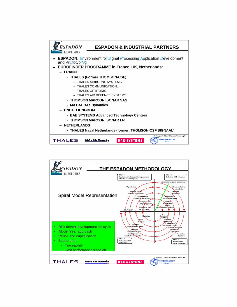
THE ESPADON METHODOLOGY
• Risk driven development life cycle• Model Year approach• Reuse and capitalisation• Support for:
Traceability Cost performance trade off
Requirements
Risk Register
Risk Analysis Definition Development Validation
Development Plan
From Previous Process
To Next/PreviousProcess
Review
Phase 1:Analysis and Selection of the requirementsallocated to SP Subsystem
GO/NO GO
Phase 2:Definition of SP Subsystem
Phase 4:Validation of SPSubsystem
Phase 3:Developmentof SP Subsystem
Example of risk:Real time performance
Example of risk:SP algorithms, ...
SP Functional definition
Computerarchitecture
choice
Simulation
Example of risk:Computing power
Functionalmodelling
Example of risk:Software development
SP production
Refinement ofarchitecture choice
Mappingdescription
Hardware/Softwaredescription
Placementof functions
Development ofperformance model
Software/Hardwaredevelopment(synthesis)
ProductionIntegration
Choicevalidation
Validationof performance model
Validationof virtual prototype
Validation ofmanufactured computer
INCREASING LEVEL OF REFINEMENT
Spiral Model Representation
D. Aulagnier/P. Meyer/H.Schurer/X.Warzee, p5
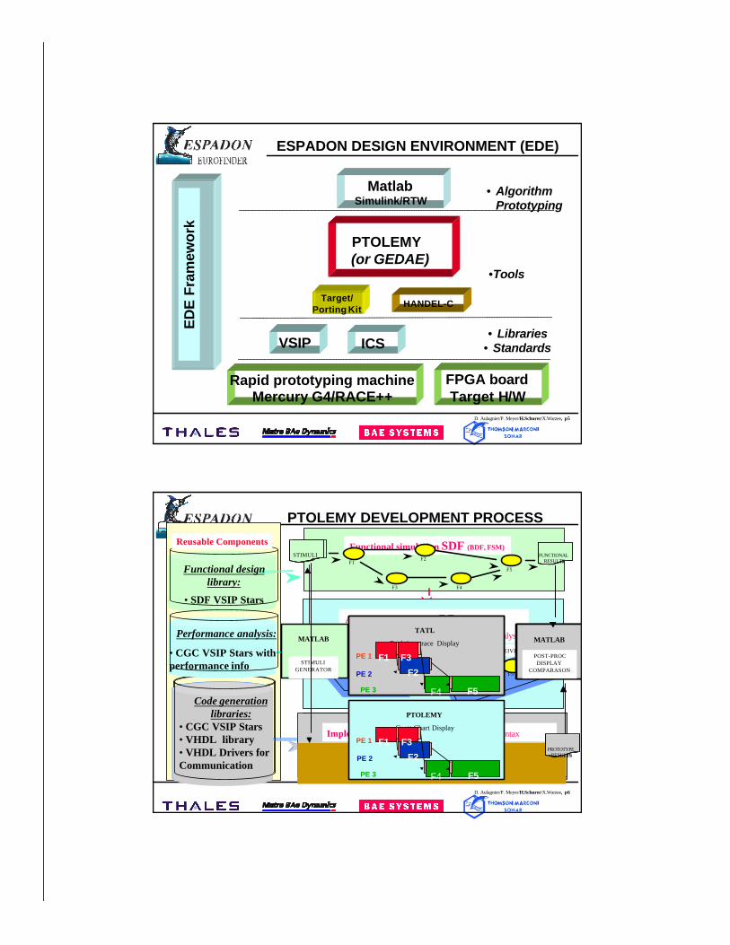
MatlabSimulink/RTW
ESPADON DESIGN ENVIRONMENT (EDE)
PTOLEMY (or GEDAE)
• AlgorithmPrototyping
Target/Porting Kit
VSIP ICS
Rapid prototyping machine Mercury G4/RACE++
• Libraries• Standards
•Tools
ED
E F
ram
ewor
k
HANDEL-C
FPGA boardTarget H/W
D. Aulagnier/P. Meyer/H.Schurer/X.Warzee, p6
Reusable Components Functional simulation SDF (BDF, FSM)
F1
F3
F2
F4
F5Functional designlibrary:
• SDF VSIP Stars
PTOLEMY DEVELOPMENT PROCESS
Implementation: CGCC code generation for Target
Run on the Target Target B
Code generationlibraries:
•CGC VSIP Stars•Target optimisedlibrary•Communicationlibrary
Target C
C code for the target--------------------------------------------------
Implementation: CGC with an “Handel-C” syntax
Code generationlibraries:
• CGC VSIP Stars• VHDL library• VHDL Drivers forCommunication
HANDEL-CC to VHDL/EDIF conversion
Architecture Design : CGTarget selection / Partitioning / Performance analysis
F1
F3
F2
F4
F5
PE1PE1PE2PE2
PE3PE3receive SendSEND/RECEIVE
Performance analysis:
• CGC VSIP Stars withperformance info
F2
FPGAFPGAreceive Send
STIMULI
STIMULIGENERATOR
MATLAB
POST-PROCDISPLAY
MATLAB
FUNCTIONALRESULTS
PTOLEMY
Gantt Chart Display
F4 F5
F2
F1 F3PE 1
PE 2
PE 3
PROTOTYPERESULTS
POST-PROCDISPLAY
COMPARASON
MATLAB
FUNCTIONALRESULTS
STIMULI
TATL
Real time trace Display
F4 F5
F2
F1 F3PE 1
PE 2
PE 3
PROTOTYPERESULTS
POST-PROCDISPLAY
COMPARASON
MATLAB
FUNCTIONALRESULTS
STIMULI
TATL
Real time trace Display
F4 F5
F2
F1 F3PE 1
PE 2
PE 3
D. Aulagnier/P. Meyer/H.Schurer/X.Warzee, p7
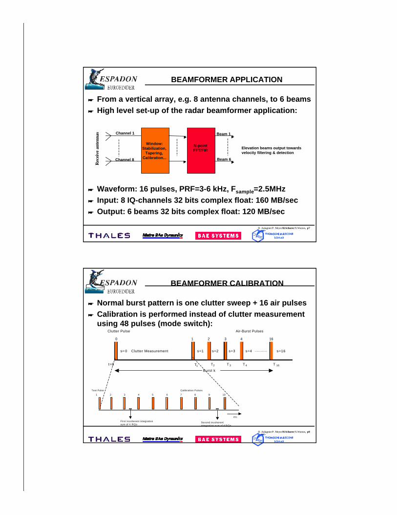
BEAMFORMER APPLICATION
* From a vertical array, e.g. 8 antenna channels, to 6 beams* High level set-up of the radar beamformer application:
* Waveform: 16 pulses, PRF=3-6 kHz, Fsample=2.5MHz* Input: 8 IQ-channels 32 bits complex float: 160 MB/sec* Output: 6 beams 32 bits complex float: 120 MB/sec
Window:Stabilization,
Tapering,Calibration...
Channel 1
Channel 8 Beam 6
Beam 1
N-pointFFT/FIR Elevation beams output towards
velocity filtering & detection
Rec
eive
ant
enna
s
D. Aulagnier/P. Meyer/H.Schurer/X.Warzee, p8
BEAMFORMER CALIBRATION
* Normal burst pattern is one clutter sweep + 16 air pulses* Calibration is performed instead of clutter measurement
using 48 pulses (mode switch):
Burst k
Clutter Measurement s=1
Air-Burst PulsesClutter Pulse
...........
T 3t=0
1 2 3 4 16
s=3s=2 s=16s=4
T 4T2 T 16
0
s= 0
T1
Calibration PulsesTest Pulse
1 2 3 4 5 6 7 8 9 10
First incoherent integrationsum of 4 RQs
Second incoherentintegration sum of 4 RQs
etc.

D. Aulagnier/P. Meyer/H.Schurer/X.Warzee, p9
BEAMFORMER DESIGN
BEAMFORMER MONITOR & CONTROL
SIGNALWEIGHTING
(CMPLX MUL)
BEAMFORMING
(FFT)
Inputinterface
tothe Filesystem
Outputinterface
tothe Filesystem
NOISEMEASUREMENT
CALCULATEWEIGHTING
FUNCTION
INCOHERENTINTEGRATION
CALCULATEPHASE
DIFFERENCE
COHERENTINTEGRATION
CALCULATEGAIN
DIFFERENCE
BEAM CALCULATION
CALIBRATION
I/Q VIDEO
level_stab_shift, CVE_phase, RF, receiver_STC
wei
ghtin
g_c
ontr
ol
BF_control BF_status
BEAMFORMER FUNCTIONAL DIAGRAM
D. Aulagnier/P. Meyer/H.Schurer/X.Warzee, p10
ESPADON PTOLEMY
* Within Ptolemy we only use:– SDF (or BDF) Domain for functional simulation– CGC Domain for Code Generation (and implementation)
* What we have developed for the benchmark is:– An extension of the Library of stars (both in SDF/BDF and CGC
available, total: 70)• Radar Library (5 components)• VSIP Core Light Library (partially, 11 components)• Support Library (e.g. components for parallel operation, 19 components)
– Target for the MERCURY Machine (G2 and G4 processor)• VSIP vectors are allocated in one buffer (per processor)• Synchronized Inter-Processor Communication for Complex Vector (The
Burst Message is always sent along with the data)
D. Aulagnier/P. Meyer/H.Schurer/X.Warzee, p11
PTOLEMY LIBRARY
* Use of VSIPL standard library– Pass pointers of VSIPL views between stars instead of data (‘int’-type)
* Develop multi- and complex-interleave star needed forcorner-turn process (in HOF domain)
* Extent CGC-BDF to handle multiprocessor architecture* Important requirements to developed elements:
– Keep library platform independent, dependency is only in the target– Make control flow explicit in the data-flow graphs
* Stars with vector output are provided with 2 extraparameters:– MAX_BUF_LENGTH: Maximum length of a vector– OUT_BUF_OPT: Number of output buffers used for each vector
D. Aulagnier/P. Meyer/H.Schurer/X.Warzee, p12
PTOLEMY LIBRARY FEATURES
* Support in-place operation (if possible)* Support rate change i.e. the output buffer is automatically
duplicated as many times as needed* Colours of the stars highlight the different kind of stars
used in the design:– Standard Ptolemy stars (WHITE) that use only std C library,– VSIPL stars (GREEN) that use the std C library and the VSIPL Core
Light library,– Application specific stars (RED) that also use MERCURY library
(ICS) and/or are specific to the ESPADON radar benchmark.
D. Aulagnier/P. Meyer/H.Schurer/X.Warzee, p13
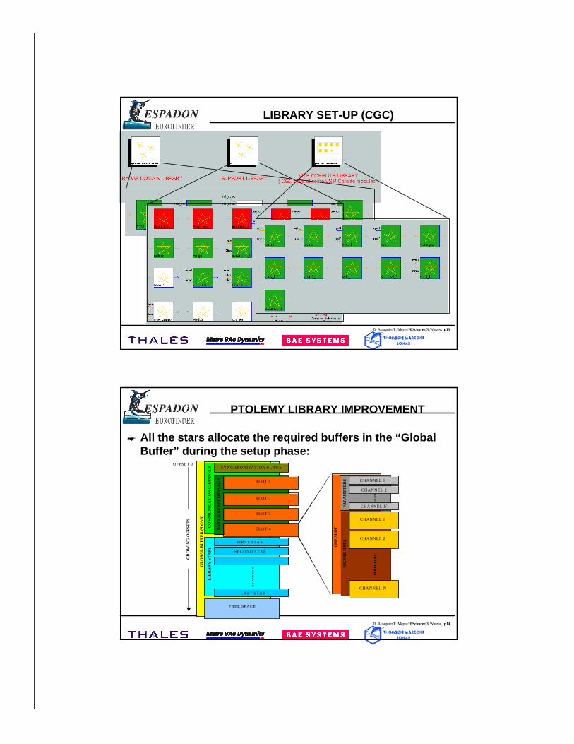
LIBRARY SET-UP (CGC)
D. Aulagnier/P. Meyer/H.Schurer/X.Warzee, p14
PTOLEMY LIBRARY IMPROVEMENT
* All the stars allocate the required buffers in the “GlobalBuffer” during the setup phase:
GL
OB
AL
BU
FF
ER
(SM
AB
)
CO
MM
UN
ICA
TIO
N C
HA
NN
EL
SL
IBR
AR
Y S
TA
RS
FREE SPACE
FIRST STAR
SECOND STAR
LAST STAR
DA
TA
& B
UR
ST M
ESS
AG
E
SYNCHRONISATION FLAGS
SLOT 1
SLOT 2
SLOT 4
SLOT 3CHANNEL 1
CHANNEL 2
CHANNEL N
CHANNEL 1
CHANNEL 2
CHANNEL N
ON
E S
LO
T
SIG
NA
L D
AT
APA
RA
ME
TE
RS
GR
OW
ING
OF
FSE
TS
OFFSET 0
D. Aulagnier/P. Meyer/H.Schurer/X.Warzee, p15
PTOLEMY MERCURY TARGET (1)
* Features– Generate a C-file for each processor, compile, load and run the
application on the machine– Use MERCURY ICS Library and VSIPL (exclusively)
⇒ Make it portable to any MERCURY machine– Arrange synchronisation and data transfer between PPCs– Data transfer uses DMA ⇒ efficient
• Synchronisation protocol uses simple flags• Support Variable Vector Length: each communication buffer is duplicated
N times (user defined) and the effective transfer length is set in real time• Memory is allocated for the maximum vector length (user defined)• Support both complex storage types (interleaved & split)• Support complex float vectors (only)
D. Aulagnier/P. Meyer/H.Schurer/X.Warzee, p16
PTOLEMY MERCURY TARGET (2)
* Features (continued)– Implement TATL Trace Tool from MERCURY– Overview of the main parameters (to be set by the user):
• Number of processors• CE id for each processor• Size of the Shared Memory Buffer (SMB) for each processor (only one
SMB is created in each processor)• Size of the “heap” is set for all processors• Communication buffer length (only one parameter for all the
communication channels)• ON/OFF switches for debug messages and TATL (trace for all stars
possible)• Give any ‘runmc’ command line option
D. Aulagnier/P. Meyer/H.Schurer/X.Warzee, p17
PTOLEMY MERCURY TARGET (3)
* Interface with VSIPL issues– If the input vector is already allocated inside the SMB and the stride of
the vector view is equal to one, then the copy is not needed.⇒ efficient transfer is possible (using In-Place operation)
(Vector view with a stride > 1 are not supported. A 2D DMA is required).– But according to VSIPL policy, any VSIPL function is allowed to move
the data to the more appropriate place (e.g. to internal memory for aDSP). Therefore the copy is always needed if we use the ‘VSIPL data’space.
– This problem is solved if we use only ‘User data’ space. In doing thiswe do not follow the defined VSIPL standard, however!
⇒ VSIPL does not fit well on a multi-processor machine like theMERCURY machine (interface VSIPL - ICS not efficient).
D. Aulagnier/P. Meyer/H.Schurer/X.Warzee, p18
ESPADON PTOLEMY ISSUES (1)
* Future work to solve known problems:– The same buffer size is applied to all communication channels
⇒ Memory allocation overhead– The Burst Message structure is hard-coded
⇒ Application dependent stars are used in the design– The BDF stars are available only for galaxies with single input & single
output, and multi-rate is not supported⇒ Strong design constraint
– The BDF stars can only be used inside a processor⇒ Design constraint
– The CGC library elements are not calibrated in terms of execution time⇒ Automatic mapping may fail
D. Aulagnier/P. Meyer/H.Schurer/X.Warzee, p19
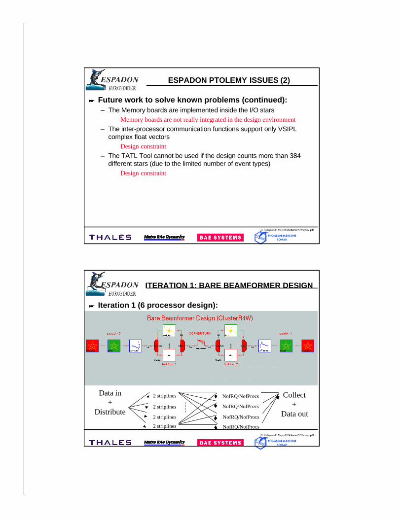
ESPADON PTOLEMY ISSUES (2)
* Future work to solve known problems (continued):– The Memory boards are implemented inside the I/O stars
⇒ Memory boards are not really integrated in the design environment– The inter-processor communication functions support only VSIPL
complex float vectors⇒ Design constraint
– The TATL Tool cannot be used if the design counts more than 384different stars (due to the limited number of event types)
⇒ Design constraint
D. Aulagnier/P. Meyer/H.Schurer/X.Warzee, p20
ITERATION 1: BARE BEAMFORMER DESIGN
* Iteration 1 (6 processor design):
Data in+
Distribute
2 striplines
2 striplines
2 striplines
2 striplines
NofRQ/NofProcs
NofRQ/NofProcs
NofRQ/NofProcs
NofRQ/NofProcs
Collect+
Data out
D. Aulagnier/P. Meyer/H.Schurer/X.Warzee, p21
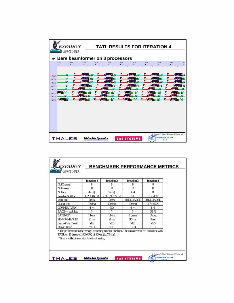
TATL RESULTS FOR ITERATION 4
* Bare beamformer on 8 processors
D. Aulagnier/P. Meyer/H.Schurer/X.Warzee, p22
Iteration 1 Iteration 2 Iteration 3 Iteration 4NofChannel 8 8 8 8NofSweep 17 17 17 17NofProc 4 (+2) 5 (+2) 4+4 8Possible NofProc 1, 2, 4, 8 (+2) 2, 3, 5, 9, 17 (+2) >1 1, 2, 4, 8Input data DMA DMA PRE-LOADED PRE-LOADEDOutput data (DMA) (DMA) (DMA) - (Pb MCS)CORNER-TURN 4->4 NO 4->4 8->8RACE++ peak load ? ? ? 53 %LATENCY 1 burst 1 burst 2 bursts 1 burstPERFORMANCE* 25 ms 21 ms 9.5 ms 9 msSupport Var. Burst L. YES YES YES YESDesign Time# 72 H 16 H 12 H 16 H* The performance is the average processing time for one burst. The measurement has been done withTATL on 10 bursts of 19000 RQ of 400 ns (i.e. 7.6 ms).# Time is without extensive functional testing.
BENCHMARK PERFORMANCE METRICS
D. Aulagnier/P. Meyer/H.Schurer/X.Warzee, p23
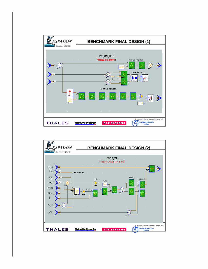
BENCHMARK FINAL DESIGN (1)
D. Aulagnier/P. Meyer/H.Schurer/X.Warzee, p24
BENCHMARK FINAL DESIGN (2)
D. Aulagnier/P. Meyer/H.Schurer/X.Warzee, p25
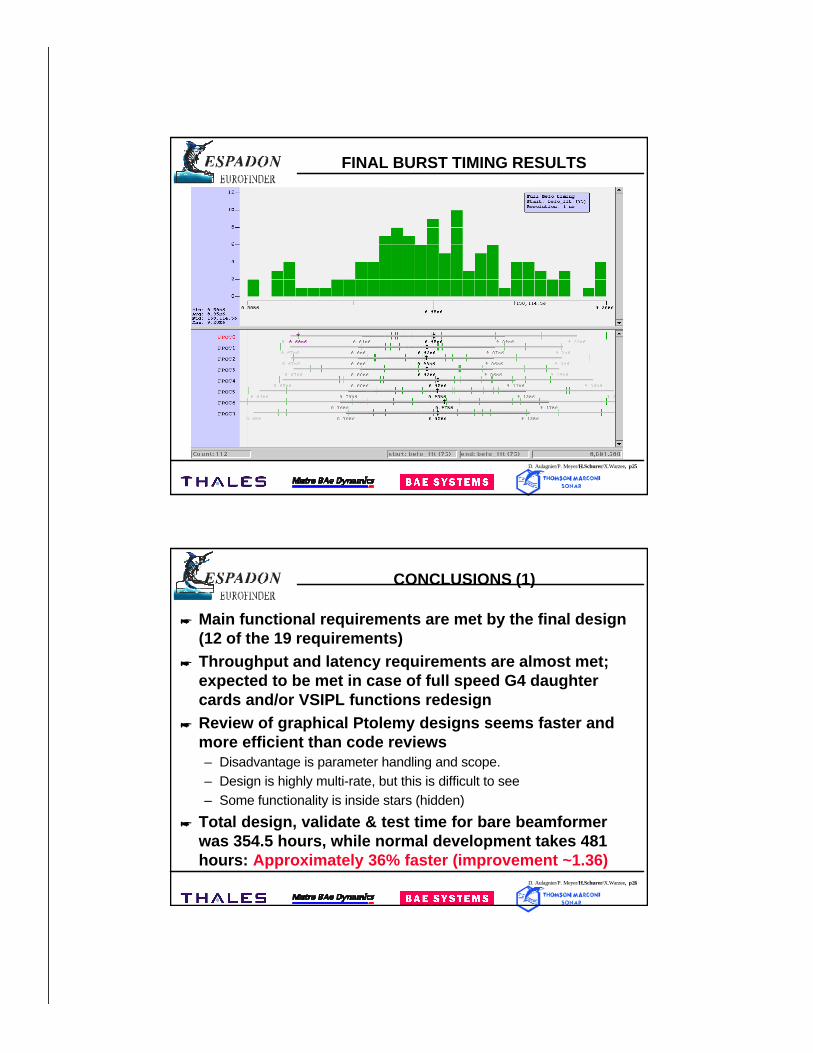
FINAL BURST TIMING RESULTS
D. Aulagnier/P. Meyer/H.Schurer/X.Warzee, p26
CONCLUSIONS (1)
* Main functional requirements are met by the final design(12 of the 19 requirements)
* Throughput and latency requirements are almost met;expected to be met in case of full speed G4 daughtercards and/or VSIPL functions redesign
* Review of graphical Ptolemy designs seems faster andmore efficient than code reviews– Disadvantage is parameter handling and scope.– Design is highly multi-rate, but this is difficult to see– Some functionality is inside stars (hidden)
* Total design, validate & test time for bare beamformerwas 354.5 hours, while normal development takes 481hours: Approximately 36% faster (improvement ~1.36)

D. Aulagnier/P. Meyer/H.Schurer/X.Warzee, p27
CONCLUSIONS (2)
* Development time from functional/architectural design toimplementation is very short: matter of days
* For which purpose can we use it?– Mainly for rapid prototyping of new algorithms– Rapid prototyping of demonstrators– Open source approach enables us to adapt the tool to our needs
* Many improvements are needed before it can be used fora complete application/project