rapportens titel - diva portal
TRANSCRIPT

Implementation of Lead-Free Soldering in Highly Reliable Applications
Ove Berglund
Master Thesis Department of Management and Engineering
LIU-IEI-TEK-A--07/0083--SE


Implementation of Lead-Free Soldering in Highly Reliable Applications
Ove Berglund
Master Thesis Department of Management and Engineering
LIU-IEI-TEK-A--07/0083--SE


Abstract
The directive of the European parliament and of the council on the Restrictionof the use of certain Hazardous Substances (RoHS) in Electrical and ElectronicEquipment (EEE) took e�ect in the European Union on July 1, 2006. Japan,California, China and Korea are all closed markets for exporters of componentscontaining lead from July 1, 2007. Taiwan and Australia are working withsimilar directives. The RoHS directive is the reason why this thesis about theimplementation of lead-free soldering in highly reliable applications is necessary.
The European Lead Free soldering NETwork (ELFNET) status survey from2005 shows that the majority of the companies are well informed, but 20% arestill not active in lead-free soldering. The Swedish industry is for the most partprepared and 95% of the components are lead-free. The transition to lead-freesoldering will have a major a�ect on logistics and administration, because theRoHS directive is 90% about administration and logistics problems. Only 10%is technical problems.
The higher melting point in lead-free soldering a�ects every stage of the lead-freemanufacturing, from assembly to testing and repair.
The major concern for highly reliable applications are that there are not enoughdata to understand to what grade lead-free solders will perform di�erently fromlead based solders. Five di�erent types of reliability testing were studied inthis thesis; vibration, mechanical shock, thermal shock, thermal cycling andcombined environments. Whiskers, voids, brittle fractures and mixed assemblyproblems were also studied. Individual tests alone should not be used to makede�nite decisions on lead-free soldering reliability. The lower reliability for lead-free solders in some tests does not necessarily mean that lead-free solders notcan be used in highly reliable applications like defence electronics.
The most important conclusions from this thesis are:
• Update or change the logistic system and mark/label according to avail-able standards.
• Secure a good board layout.
• Secure a good process control.
• Alternative surface board should be used. Tin-silver-copper (SAC) is themost reliable solder and Electroless Nickel/Immersion Gold (ENIG) is themost reliable surface �nish.
• Remember that the higher temperature a�ects every stage of the manu-facturing.
• No increased problems with whiskers or risk of high voiding levels.
• Mixed assembly is a risk. Compatibility and contamination risks must betaken seriously.
• Which environment will the applications be in? If it is not a highly vibrat-ing and thermal cycling environment, lead-free soldering should be safe touse.
i

ii

Sammanfattning
Europaparlamentets och rådets direktiv om begränsning av användningen avvissa farliga ämnen i elektriska och elektroniska produkter började gälla i Eu-ropeiska unionen 1 juli, 2006. Japan, Kalifornien, Kina och Korea är alla stängdamarknader för exportörer av komponenter som innehåller bly från och med 1 juli,2007. Taiwan och Australien arbetar med liknande direktiv. RoHS-direktivetär anledningen till varför detta examensarbete om implementeringen av blyfrilödning i högtillförlitliga applikationer är nödvändigt.
En undersökning från 2005 av ELFNET visar att majoriteten av företagen ärväl informerade, men 20% är fortfarande i aktiva med blyfri lödning. Densvenska industrin är till största delen väl förberedd och 95% av komponenternaär blyfria. Övergången till blyfri lödning kommer att ha stor e�ekt på logistikoch administration, därför att 90% är administrations- och logistikproblem iRoHS-direktivet. Bara 10% är tekniska problem.
Den högre smälttemperaturen i blyfri lödning påverkar varje steg av den blyfriatillverkningen, från montering till testning och reparation.
Den stora oron för högtillförlitliga applikationer är att det inte �nns tillräckligtmed data för att förstå i vilken grad som blyfria lod kommer att bete sig annor-lunda jämfört med blybaserade lod. Fem olika typer av tillförlitlighetstester harundersökts i detta examensarbete; vibration, mekanisk chock, termisk chock,termisk cykling och kombinerade tester. Whiskers, voids, sprödbrott och blan-dad montering studerades också. Individuella tester ska inte användas för attta några de�nitiva beslut om blyfri lödnings tillförlitlighet. Den lägre tillför-litligheten för blyfria lod i en del tester behöver nödvändigtvis inte betydaatt blyfria lod inte kan användas i högtillförlitliga applikationer som försvars-elektronik.
De viktigaste slutsatserna från detta examensarbete är:
• Uppdatera eller byt logistiskt system och märk enligt tillgängliga stan-darder.
• Säkerställ en bra kretskortsdesign.
• Säkerställ en bra processkontroll.
• Alternativa mönsterkort bör användas. SAC är det tillförlitligaste lodetoch ENIG är den tillförlitligaste ytbehandlingen.
• Kom ihåg att den ökade temperaturen påverkar varje steg i tillverkningen.
• Inga ökade problem med whiskers eller stort antal voids.
• Blandmontage är riskfyllt. Kompatibilitet och risker med kontamineringmåste tas på allvar.
• Vilken miljö kommer applikationen att be�nna sig i? Är det inte en starktvibrerande eller temperaturcyklisk miljö bör blyfri lödning vara säkert attanvända.
iii

iv

Acknowledgements
This thesis was carried out at the Department of Management and Engineering,Linköping Institute of Technology and at Saab Systems, Naval Systems DivisionSweden. The work was carried out between September 2006 and March 2007 atSaab Systems main o�ce at Järfälla, near Stockholm. The thesis is a compulsorypart of the education to receive a degree in Master of Science in ElectronicsDesign from Linköping Institute of Technology. The examiner at LinköpingInstitute of Technology was Mattias Lindahl. The supervisor at Saab Systemswas Christer Melander.
I would like to thank my supervisor Christer Melander and Saab personnel atSaab Systems who have been very helpful during this thesis. Christer helped megetting in contact with relevant people and collecting information. I was giventhe opportunity to participate in meetings and a seminar arrange by KIMABand IVF.
I would like to thank my examiner Mattias Lindahl who supported me with hisanalysing and questioning attitude. He also helped me with questions regardingthe Asian market.
I would like to thank Per-Erik Tegehall, Lars-Gunnar Klang, Conny Svensson,Jan-Eric Spjuth, Magnus Porsmark, Thomas Cadring and Peter Back.
I would also like to thank Håkan Hådeby, Anders Ekelöf, Benny Gustafson,Ove Isaksson, Kent Stenberg and Axel Tchimanga at Ericsson in Kista, nearStockholm. I would like to thank ABB and their connections with ENICS, whichgave me the opportunity to meat Peter Back at ENICS in Malmö. Finally Iwould like to thank everyone who supported and helped me during my thesis.I am grateful to Saab Systems for giving me this opportunity.
Stockholm, March 2007
Ove Berglund
v

vi

Nomenclature & De�nitions
AOI Automatic Optical Inspection
BGA Ball Grid Array. The pins are replaced by balls of solder stuck tothe bottom of the package
Bodycote In house analyse company to Saab. Supplier of specialist testingand thermal processing services. A vital provider of heat treat-ments, hot isostatic pressing, metallurgical coatings and testingservices to industry.
CET Combined Environment Tests
CSP Chip Scale Package is a type of integrated circuit chip carrier thathas no pins or wires but uses contact pads instead.
Delta T Delta T is the di�erence between the highest and lowest temper-ature observed across the board.
DoD U.S. Department of Defense
EEE Electrical and Electronic Equipment
ELFNET European Lead Free soldering NETwork. ELFNET is a Europeanresearch network of the national organisations, technical expertsand industry bodies in micro-electronics. ELFNET provides aplatform to coordinate, integrate and optimise research, enablingelectronics producers in the EU to meet an EU directive to intro-duce lead-free soldering by 1 July 2006.
ENICS Subcontractor (not to Saab Systems)
ENIG Electroless Nickel/Immersion Gold
EoL End of Life
EPA Environmental Protection Agency
EPHC Environment Protection and Heritage Council
FR4 Flame Resistant 4. Designation for a �berglass and epoxy sub-strate material. A type of material used for making a printedcircuit board.
GPL Green Purchasing Law
HARL Home Appliances Recycling Law
HASL Hot Air Solder Leveling
I-Ag Immersion silver
I-Sn Immersion tin
ILS Intergrated Logistic Support
vii

iNEMI The International Electronics Manufacturing Initiative (iNEMI) isan industry-led consortium whose mission is to assure leadershipof the global electronics manufacturing supply chain.
IPC IPC is the formal name of a United States-based trade associ-ation dedicated to furthering the competitive excellence and �-nancial success of its members worldwide, who are participantsin the electronic interconnect industry. In pursuit of these objec-tives, IPC will devote resources to management improvement andtechnology enhancement programs, the creation of relevant stan-dards, protection of the environment, and pertinent governmentrelations.
IVF Industrial Research and Development Corporation is the Swedishengineering industry's research institute.
JCAA/JG Joint Council on Aging Aircraft/Joint Group. A DoD sponsoredconsortium was founded in May of 2001 to evaluate lead-free sol-ders and �nishes and to determine whether they are suitable foruse in high reliability electronics. This consortium is jointly man-aged by the JCAA and the Joint Group on Pollution Prevention(JG-PP). The consortium's project is called the JCAA/JG-PPLead-Free Solder Project and it has members from all branches ofthe Armed Services, NASA, Boeing, Rockwell-Collins, Raytheon,BAE Systems, ACI, Lockheed Martin, Texas Instruments, NCMS,JPL, Sandia National Labs and Marshall Space Flight Centeramong others.
JEDEC The JEDEC Solid State Technology Association (Once known asthe Joint Electron Device Engineering Council). Is the semicon-ductor engineering standardization body of the Electronic Indus-tries Alliance (EIA), a trade association that represents all areasof the electronics industry.
JEITA Japan Electronics and Information Technology Industries Associ-ation. Their objective is to promote the healthy manufacturing,international trade and consumption of electronics products andcomponents in order to contribute to the overall development ofthe electronics and information technology (IT) industries, andthereby further Japan's economic development and cultural pros-perity.
LEAB Leab Group is a contract manufacturer
Legotronic PCB subcontractor to Saab Systems
Lindebergh PCB subcontractor to Saab Systems
LPEUR Law for the Promotion of E�ective Utilisation of Resources
NASA National Aeronautics and Space Administration
viii

NOTE NOTE is a contract supplier of �exible electronics production andcustomised logistics.
NPL National Physical Laboratory. NPL is the United Kingdom's na-tional standards laboratory, an internationally respected and inde-pendent centre of excellence in research, development and knowl-edge transfer in measurement and materials science.
NSD Naval Systems Division
MII Ministry of Information Industry
OSP Organic Solderability Preservative
PBB Polybrominated Biphenyls
PBDE Polybrominated Diphenyl Ethers
PBGA Plastic Ball Grid Array
PCB Printed Circuit Board
PWB Printed Wiring Board
QFP Quad Flat Pack. High lead count package. Fine-pitch devices,lead pitch is often 0.66 mm down to 0.3 mm.
RoHS Restriction of the use of certain Hazardous Substances.
SAC SnAgCu. Tin-Silver-Copper
SAC305 The �rst two numbers are the percentage of silver (3.0%) and thelast number the percentage of copper (0.5%).
SACB SnAgCuBi. Tin-Silver-Copper-Bismuth
SAEEC South African Electrotechnical Export Council
SMT Surface Mount Technology
SMTA Surface Mount Technology Association. Established in 1984, is anon-pro�t international association of companies and individualsinvolved in all aspects of the electronics industry. The Associa-tion is dedicated to the advancement of the electronics industrythrough member education and interaction.
SnAg Tin-Silver
SnBi Tin-Bismuth
SnCu Tin-Copper
SnCuNi Tin-Copper-Nickel
SnPb Tin-Lead
SnPbAg Tin-Lead-Silver
SnZn Tin-Zinc
ix

TAC Technical Adaptation Committee
TAL Time Above Liquid
Td Decomposition temperature
Tg Glass-transition temperature
TTG Technical Transfer Group. A working group in Saab which areworking with issues regarding the RoHS directive.
VOC Volatile Organic Compound
WEEE Waste Electrical and Electronic Equipment
x

Contents
1 Introduction 11.1 Company description . . . . . . . . . . . . . . . . . . . . . . . . . 11.2 Background . . . . . . . . . . . . . . . . . . . . . . . . . . . . . . 11.3 Purpose . . . . . . . . . . . . . . . . . . . . . . . . . . . . . . . . 21.4 Research questions . . . . . . . . . . . . . . . . . . . . . . . . . . 21.5 Delimitations . . . . . . . . . . . . . . . . . . . . . . . . . . . . . 2
2 Method 52.1 Research methodology . . . . . . . . . . . . . . . . . . . . . . . . 5
2.1.1 Qualitative - Quantitative research . . . . . . . . . . . . . 62.2 Interview methodology . . . . . . . . . . . . . . . . . . . . . . . . 62.3 Theoretical studies . . . . . . . . . . . . . . . . . . . . . . . . . . 72.4 Data sources . . . . . . . . . . . . . . . . . . . . . . . . . . . . . 7
2.4.1 Saab . . . . . . . . . . . . . . . . . . . . . . . . . . . . . . 72.4.2 External sources . . . . . . . . . . . . . . . . . . . . . . . 7
2.5 Structure of the thesis . . . . . . . . . . . . . . . . . . . . . . . . 8
3 International legislations 113.1 EU, RoHS directive . . . . . . . . . . . . . . . . . . . . . . . . . . 12
3.1.1 Exceptions . . . . . . . . . . . . . . . . . . . . . . . . . . 133.2 USA . . . . . . . . . . . . . . . . . . . . . . . . . . . . . . . . . . 133.3 Japan . . . . . . . . . . . . . . . . . . . . . . . . . . . . . . . . . 133.4 China . . . . . . . . . . . . . . . . . . . . . . . . . . . . . . . . . 143.5 Australia . . . . . . . . . . . . . . . . . . . . . . . . . . . . . . . 143.6 South Africa . . . . . . . . . . . . . . . . . . . . . . . . . . . . . 15
4 Current status on lead-free soldering 174.1 Current status at Saab . . . . . . . . . . . . . . . . . . . . . . . . 18
5 Logistics 215.1 Storage . . . . . . . . . . . . . . . . . . . . . . . . . . . . . . . . 215.2 Marking . . . . . . . . . . . . . . . . . . . . . . . . . . . . . . . . 21
5.2.1 IPC1066/IPC-JEDEC STD NR 97 . . . . . . . . . . . . . 22
6 Lead-free issues and alternatives 256.1 Education . . . . . . . . . . . . . . . . . . . . . . . . . . . . . . . 256.2 Temperature . . . . . . . . . . . . . . . . . . . . . . . . . . . . . 26
6.2.1 Nitrogen . . . . . . . . . . . . . . . . . . . . . . . . . . . . 28
xi

6.3 Soldering process . . . . . . . . . . . . . . . . . . . . . . . . . . . 286.4 Solder . . . . . . . . . . . . . . . . . . . . . . . . . . . . . . . . . 29
6.4.1 Tin-silver-copper . . . . . . . . . . . . . . . . . . . . . . . 296.4.2 Tin-silver-copper-bismuth/Tin-silver-bismuth . . . . . . . 306.4.3 Tin-zinc . . . . . . . . . . . . . . . . . . . . . . . . . . . . 306.4.4 Tin-copper . . . . . . . . . . . . . . . . . . . . . . . . . . 306.4.5 Tin-silver . . . . . . . . . . . . . . . . . . . . . . . . . . . 30
6.5 Components . . . . . . . . . . . . . . . . . . . . . . . . . . . . . . 316.5.1 Supply . . . . . . . . . . . . . . . . . . . . . . . . . . . . . 31
6.6 Printed surface boards . . . . . . . . . . . . . . . . . . . . . . . . 316.7 Flux . . . . . . . . . . . . . . . . . . . . . . . . . . . . . . . . . . 326.8 Surface �nishes . . . . . . . . . . . . . . . . . . . . . . . . . . . . 32
6.8.1 Electroless Nickel/Immersion Gold . . . . . . . . . . . . . 326.8.2 Immersion silver . . . . . . . . . . . . . . . . . . . . . . . 336.8.3 Hot Air Solder Levelling . . . . . . . . . . . . . . . . . . . 346.8.4 Organic Solderability Preservative . . . . . . . . . . . . . 346.8.5 Immersion tin . . . . . . . . . . . . . . . . . . . . . . . . . 34
6.9 Inspection . . . . . . . . . . . . . . . . . . . . . . . . . . . . . . . 356.10 Rework and repair . . . . . . . . . . . . . . . . . . . . . . . . . . 35
7 Reliability of lead-free soldering 377.1 Reliability testing . . . . . . . . . . . . . . . . . . . . . . . . . . . 38
7.1.1 Vibration . . . . . . . . . . . . . . . . . . . . . . . . . . . 387.1.2 Mechanical shock . . . . . . . . . . . . . . . . . . . . . . . 387.1.3 Thermal shock . . . . . . . . . . . . . . . . . . . . . . . . 387.1.4 Thermal cycling . . . . . . . . . . . . . . . . . . . . . . . 397.1.5 Combined environments . . . . . . . . . . . . . . . . . . . 417.1.6 Salt fog . . . . . . . . . . . . . . . . . . . . . . . . . . . . 437.1.7 Humidity . . . . . . . . . . . . . . . . . . . . . . . . . . . 437.1.8 Test summary . . . . . . . . . . . . . . . . . . . . . . . . 43
7.2 Whiskers . . . . . . . . . . . . . . . . . . . . . . . . . . . . . . . 447.3 Voids . . . . . . . . . . . . . . . . . . . . . . . . . . . . . . . . . . 457.4 Brittle fractures . . . . . . . . . . . . . . . . . . . . . . . . . . . . 467.5 Mixed assembly . . . . . . . . . . . . . . . . . . . . . . . . . . . . 47
7.5.1 Metallurgical imbalance . . . . . . . . . . . . . . . . . . . 497.5.2 Contamination . . . . . . . . . . . . . . . . . . . . . . . . 497.5.3 Compatibility . . . . . . . . . . . . . . . . . . . . . . . . . 49
8 Discussion 518.1 What legislations are there . . . . . . . . . . . . . . . . . . . . . 518.2 Status on lead-free soldering . . . . . . . . . . . . . . . . . . . . . 518.3 Impact on logistics and administration . . . . . . . . . . . . . . . 528.4 A�ect on the solder process . . . . . . . . . . . . . . . . . . . . . 528.5 A�ects of the increased solder temperature . . . . . . . . . . . . 578.6 Is it safe to use lead-free soldering for highly reliable applications? 578.7 Criticism of chosen methodology . . . . . . . . . . . . . . . . . . 59
8.7.1 Sources of error . . . . . . . . . . . . . . . . . . . . . . . . 608.7.2 Validity . . . . . . . . . . . . . . . . . . . . . . . . . . . . 618.7.3 Reliability . . . . . . . . . . . . . . . . . . . . . . . . . . . 61
xii

9 Conclusions 639.1 General . . . . . . . . . . . . . . . . . . . . . . . . . . . . . . . . 639.2 Saab Systems . . . . . . . . . . . . . . . . . . . . . . . . . . . . . 649.3 Future work . . . . . . . . . . . . . . . . . . . . . . . . . . . . . . 65
A Glossary 73
B RoHS directive 2002/95/EC 75
xiii

xiv

List of Figures
5.1 Humidity labels [48] . . . . . . . . . . . . . . . . . . . . . . . . . 225.2 Lead-free labels [46, 47] . . . . . . . . . . . . . . . . . . . . . . . 23
6.1 Temperature pro�les [31] . . . . . . . . . . . . . . . . . . . . . . . 266.2 Storage e�ect [20] . . . . . . . . . . . . . . . . . . . . . . . . . . . 34
7.1 Cross-over point [33] . . . . . . . . . . . . . . . . . . . . . . . . . 407.2 Failure after thermal cycling [63] . . . . . . . . . . . . . . . . . . 417.3 Failure regions [21] . . . . . . . . . . . . . . . . . . . . . . . . . . 427.4 Image of whiskers [25] . . . . . . . . . . . . . . . . . . . . . . . . 447.5 Optical and electron microscope images of voids [64] . . . . . . . 467.6 Image of a crack in a solder joint [30] . . . . . . . . . . . . . . . . 477.7 Combination of material [63] . . . . . . . . . . . . . . . . . . . . 48
xv

xvi
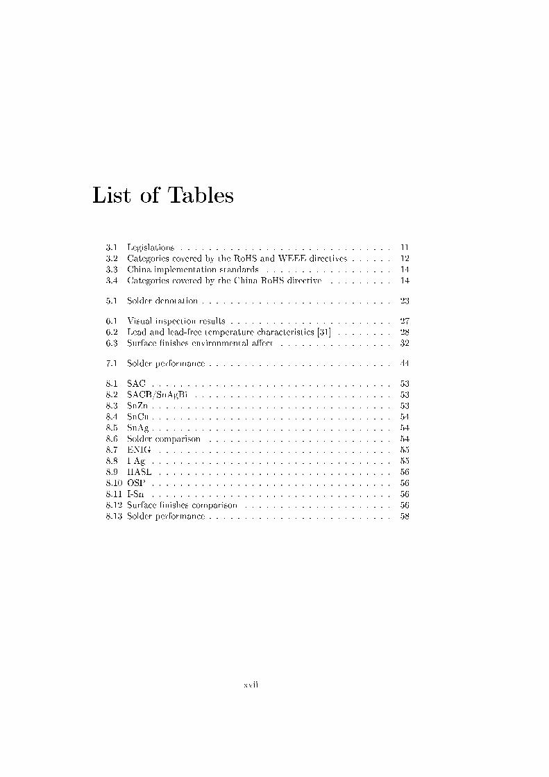
List of Tables
3.1 Legislations . . . . . . . . . . . . . . . . . . . . . . . . . . . . . . 113.2 Categories covered by the RoHS and WEEE directives . . . . . . 123.3 China implementation standards . . . . . . . . . . . . . . . . . . 143.4 Categories covered by the China RoHS directive . . . . . . . . . 14
5.1 Solder denotation . . . . . . . . . . . . . . . . . . . . . . . . . . . 23
6.1 Visual inspection results . . . . . . . . . . . . . . . . . . . . . . . 276.2 Lead and lead-free temperature characteristics [31] . . . . . . . . 286.3 Surface �nishes environmental a�ect . . . . . . . . . . . . . . . . 32
7.1 Solder performance . . . . . . . . . . . . . . . . . . . . . . . . . . 44
8.1 SAC . . . . . . . . . . . . . . . . . . . . . . . . . . . . . . . . . . 538.2 SACB/SnAgBi . . . . . . . . . . . . . . . . . . . . . . . . . . . . 538.3 SnZn . . . . . . . . . . . . . . . . . . . . . . . . . . . . . . . . . . 538.4 SnCu . . . . . . . . . . . . . . . . . . . . . . . . . . . . . . . . . . 548.5 SnAg . . . . . . . . . . . . . . . . . . . . . . . . . . . . . . . . . . 548.6 Solder comparison . . . . . . . . . . . . . . . . . . . . . . . . . . 548.7 ENIG . . . . . . . . . . . . . . . . . . . . . . . . . . . . . . . . . 558.8 I-Ag . . . . . . . . . . . . . . . . . . . . . . . . . . . . . . . . . . 558.9 HASL . . . . . . . . . . . . . . . . . . . . . . . . . . . . . . . . . 568.10 OSP . . . . . . . . . . . . . . . . . . . . . . . . . . . . . . . . . . 568.11 I-Sn . . . . . . . . . . . . . . . . . . . . . . . . . . . . . . . . . . 568.12 Surface �nishes comparison . . . . . . . . . . . . . . . . . . . . . 568.13 Solder performance . . . . . . . . . . . . . . . . . . . . . . . . . . 58
xvii

xviii

Chapter 1
Introduction
1.1 Company description
Saab Systems, Naval Systems Division (NSD) encompasses naval related busi-ness activities in Sweden and Australia. Naval Systems Division Sweden shallin cooperation with Saab Systems other divisions and sta� units sell, develop,and deliver naval Combat Management Systems. Reliable through-life supportof deliveries is an essential part of Naval Systems Division customer image. Thecustomers are shipyards and governmental organizations in Sweden and inter-nationally.
1.2 Background
The background to this thesis is the RoHS directive which took a�ect in July1, 2006. The purpose of the directive is to approximate the laws of the EUmember states on RoHS in EEE. RoHS should also contribute to the protectionof human health and the environment.
There are six restricted substances in the RoHS directive and lead is one ofthem. No new EEE released after July 1, 2006 are allowed to contain therestricted substances. There are two categories and several exceptions in theEU directives. Military applications (like Saab Systems) are excepted from theRoHS directive. Exceptions will be carried out only on technical criteria. Theexceptions are valid for a maximum period of four years and then subject to areview. The exceptions are granted for speci�c applications and not to wholeproducts.
However, Saab Systems is a�ected in several ways, through customer demandsand component manufacturers. Because of the indirect consequences for SaabSystems and the uncertainty regarding how long the exceptions are valid, a studyabout the implementation of lead-free soldering in highly reliable applicationswere needed.
1

Introduction
1.3 Purpose
The purpose of this thesis is to investigate the consequences of the transition tolead-free soldering in highly reliable applications. This shall be made by litera-ture studies, interviews, meetings with Saab and their subcontractors and othercompanies. The purpose is also to present available solutions to the problemswith lead-free soldering.
1.4 Research questions
A number of questions were arisen before and during the thesis process. Thesewere the questions that Saab Systems in Järfälla were interested in making aninvestigation on:
1. What legislations are thereLead-free soldering has to be used because of the RoHS directive. Thisquestion had to be answered to understand the RoHS directive and thelegislations in other relevant coutries.
2. Status on lead-free solderingThis question had to be answered to know how far the transition to lead-freesoldering has come.
3. Impact on logistics and administrationThis question had to be answered to understand the RoHS directive impacton logistics and administration.
4. A�ect on the solder processThis question had to be answered to understand the impact on the wholesolder process.
5. A�ects of the increased solder temperatureThis question had to be answered to understand the problems with theelevated temperature in lead-free soldering.
6. Is it safe to use lead-free soldering for highly reliable applications?Probably one of the most important question within lead-free solderingtoday.
1.5 Delimitations
This thesis work is limited to 20 working weeks and some delimitation need tobe carried out to reach the objective within the timeframe. Therefore it was notpossible to investigate the consequences of the transition to lead-free solderingfor every relevant department in Naval Systems Division Sweden. Consequencesfor the development, logistics and production departments were analyzed.
No investigation has been made for the purchase, test and delivery, after salesand ILS (Intergrated Logistic Support) departments. Areas that are mentioned
2

1.5 Delimitations
in this thesis, but need more attention are rework and repair, compatibility and�ux.
There are six restricted substances in the RoHS directive; lead, cadmium,mercury, hexavalent chromium, polybrominated biphenyls and polybrominateddiphenyl ethers. Lead is the only substance investigated in this thesis.
3

Introduction
4

Chapter 2
Method
This chapter describes the choice of methodology. Some theory about researchmethodology and interview methodology is presented. Criticism about the cho-sen method is discussed in chapter eight, Discussion. The following books havebeen used to write this chapter [54, 55, 56, 57].
A research methodology was used to understand the issues with implementinglead-free soldering. A qualitative study had to be used because not enough workhas been done to make a quantitative study. Interviews and literature studieswas a natural way to investigate the lead-free phenomenon. Therefore people inthe ELFNET and the Industrial Research and Development Corporation (IVF)were contacted. To understand other companies problems and status on lead-free soldering interviews with subcontractors and other companies were made.
Documents from laboratories and research institutes were used to make theliterature study. Relevant articles, journals and other written sources were alsoused. The National Physical Laboratory (NPL) in the United Kingdom, SurfaceMount Technology Association (SMTA), Joint Council on Aging Aircraft/JointGroup (JCAA/JG) and the ELFNET were found to be reliable sources and hadsome interesting documents. New information was collected to the end of thethesis.
2.1 Research methodology
This thesis is the result of a case study at Saab Systems main o�ce in Järfälla,near Stockholm about the implementation of lead-free soldering in highly reli-able applications. A case study can be made in several approaches, Patel andDavidsson describes the research process in sex stages. [57]
5

Method
1. Collect knowledge
2. Specify the problem
3. Decide
- research group
- research planning
- technique to collect information
4. Carrying through
5. Process/Analyse
6. Account/Report
It would be best to follow the stages step by step, but that is not possible in re-ality. The literature study, data collection and analyse were made parallel. Thewriting of this thesis has been made continuously as new information arrived.The sources to this thesis are interviews, internal documents and other writtensources.
2.1.1 Qualitative - Quantitative research
Quantitative case studies testing a theory and qualitative case studies createa theory. Qualitative data consists of detailed descriptions of situations, oc-currences, people, interaction and observed behaviours. The information canconsist of quotations, protocols, letters, and case records.
A qualitative study is presented with words, however qualitative data is pre-sented with numbers. Quantitative information can tell us how many, howmuch and what the distribution looks like. Qualitative case studies are basedon qualitative information which is collected from interviews, observations anddocuments. Quantitative information from e.g. survey studies can be used tosupport the results from the qualitative data. This thesis is made with theassumption of a qualitative method, because the purpose is to understand themeaning of a certain phenomenon.
2.2 Interview methodology
The interviews were semi structured, which means that they were formal andcontrolled by a number of questions or problems which will be explored. Theresults are a combination of open and �rm answers. This kind of interviewsmakes it possible to adapt to the situation as it develops.
In some cases the interviews have been unstructured because insu�cient infor-mation has been available for relevant questions. This was the case especiallyin the beginning of the study. The unstructured interview is supposed to giveenough information to ask related questions later in the case study.
6
2.3 Theoretical studies
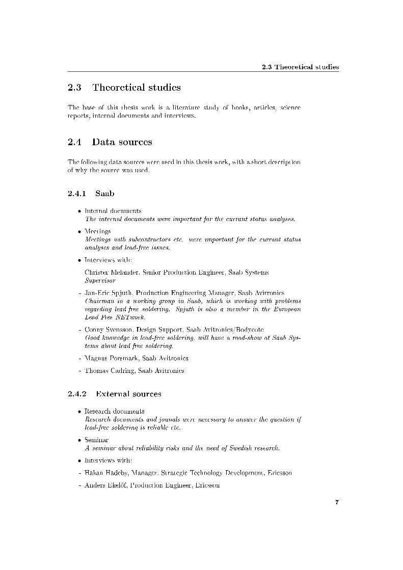
2.3 Theoretical studies
The base of this thesis work is a literature study of books, articles, sciencereports, internal documents and interviews.
2.4 Data sources
The following data sources were used in this thesis work, with a short descriptionof why the source was used.
2.4.1 Saab
• Internal documentsThe internal documents were important for the currant status analyses.
• MeetingsMeetings with subcontractors etc. were important for the currant statusanalyses and lead-free issues.
• Interviews with:
- Christer Melander, Senior Production Engineer, Saab SystemsSupervisor
- Jan-Eric Spjuth, Production Engineering Manager, Saab AvitronicsChairman in a working group in Saab, which is working with problemsregarding lead-free soldering. Spjuth is also a member in the EuropeanLead Free NETwork.
- Conny Svensson, Design Support, Saab Avitronics/BodycoteGood knowedge in lead-free soldering, will have a road-show at Saab Sys-tems about lead-free soldering.
- Magnus Porsmark, Saab Avitronics
- Thomas Cadring, Saab Avitronics
2.4.2 External sources
• Research documentsResearch documents and jounals were necessary to answer the question iflead-free soldering is reliable etc.
• SeminarA seminar about reliability risks and the need of Swedish research.
• Interviews with:
- Håkan Hådeby, Manager, Strategic Technology Development, Ericsson
- Anders Ekelöf, Production Engineer, Ericsson
7

Method
- Benny Gustafson, Specialist-SMA Process, Engineering PBA Technology,Ericsson
- Ove Isaksson, Production Engineer, Ericsson
- Kent Stenberg, Senior Production Engineer, Ericsson
- Axel Tchimanga, PBA Technology, EricssonEricsson is also producing highly reliable applications, therefore they couldprovide much useful information. Their information was useful for an-swering research questions number 2-6.
- Peter Back, Director Manufacturing Engineering, EnicsBack has worked with lead-free issues for a long time and could thereforeprovide much useful information. He had information regarding researchquestions number 2-6.
- Per-Erik Tegehall, Ph.D. IVFIVF is the Swedish national network in the European Lead Free NET-work. Tegehall was interviewed because he had information about lead-freereliability, research question number six.
- Lars-Gunnar Klang, Cross Technology SolutionsKlang has a long experience in lead-free soldering issues. He had infor-mation about lead-free reliability, research question number six.
2.5 Structure of the thesis
The thesis is divided into nine chapters and two appendixes.
Chapter 1: Introduction to the thesis.
Chapter 2: Describes the methodology in the thesis.
Chapter 3: Describes the international legislations on hazardous substancesin the EU, USA, Japan, China, Australia and South Africa. The Euro-pean countries were the �rst to restrict the use of hazardous substances.The RoHS directive is described in the beginning of this chapter. Thelegislations in the other regions are also described.
Chapter 4: Presents the current status on lead-free soldering with focus onEurope and Saab.
Chapter 5: Describes issues regarding storage and marking.
Chapter 6: Describes issues with lead-free soldering such as education, inspec-tion, temperature, rework and repair. Lead-free alternatives regardingsolder, surface �nishes, etc. are presented.
Chapter 7: Presents the results of some reliability testing. Problems withwhiskers, voids, mixed assembly, etc. are also presented.
Chapter 8: The questions of interest are discussed and some criticism of thechosen methodology.
8

2.5 Structure of the thesis
Chapter 9: Compiles the general conclusions.
Appendix A: Glossary
Appendix B: RoHS directive 2002/95/EC
9

Method
10

Chapter 3
International legislations
This chapter describes the EU, RoHS directive and the legislations in the USA,Japan, China, Australia and South Africa.
The EU, Japan, California (the USA has no domestic regulation) and Chinaare closed markets for exporters from the dates as set out. South Africa has nopending directive. Table 3.1 shows the di�erence between four regions. [60]
EU July 1, 2006Japan July 1, 2006California Jan 1, 2007China Mar 1, 2007Korea July 1, 2007Taiwan PendingAustralia Pending
EU China Japan CaliforniaRestrictedMaterials
6 materials Same as EU Same asEU, butinfo. only
4 havy met-als
Scope 10 cate-gories
Long list(incl. cap-ital equip-ment)
7 home app.& computerproducts
Video dis-play device
Exemption De�ned No petition Not apllica-ble
Same as EU
MarkingReq.
None Yes Yes None
PackagingMaterials
No impact Non-toxic /recyclable
None None
Tetsing/Certi�ca-tion
No prerequi-site
China Com-pulsory Cer-ti�cation
No prerequi-site
No prerequi-site
Table 3.1: Legislations
11

International legislations
3.1 EU, RoHS directive
The directive 2002/95/EC of the European parliament and of the council onthe Restriction of the use of certain Hazardous Substances in electrical and elec-tronic equipment took e�ect in the European Union on July 1, 2006. [41] Thepurpose of the directive is to approximate the laws of the EU member stateson restriction of the use of hazardous substances in Electrical and ElectronicEquipment. RoHS should also contribute to the protection of human healthand the environmentally sound recovery and disposal of WEEE (Waste Electri-cal and Electronic Equipment). [42] The RoHS directive is complementary tothe WEEE directive. They were created for the same reasons, but with di�erentpurposes. There are six restricted substances in the RoHS directive; lead, cad-mium, mercury, hexavalent chromium, PBB (Polybrominated Biphenyls) andPBDE (Polybrominated Diphenyl Ethers). The directive increases the possibil-ity to make an economic pro�tability of recycling of WEEE and decrease thenegative health impact on workers in recycling plants. The regulations con-cerning the producer responsibility of the use of certain hazardous substancesin EEE covers eight of ten categories in the WEEE directive. See table 3.2 forthe categories covered by the RoHS and WEEE directives. [41] RoHS coversall products in the WEEE directive except two categories; medical equipment(category eight) and monitoring and control equipment (category nine). Themaximum concentration level, by weight in homogenous materials is 0.1% forall the substances except cadmium, which has a maximum of 0.01%. [24]
Homogenous material is a concept in the RoHS directive which is a material thatcan not be mechanically disjointed into other materials. Homogenous means "ofuniform composition throughout". Mechanical disjointed means that materialscan be separated by mechanical actions such as unscrewing, cutting, crushing,grinding and abrasive processes. [24]
1. Large household appliances2. Small household appliances3. IT and telecommunications equipment4. Consumer equipment5. Lighting equipment6. Electrical and electronic tools (with the exception of large-scale sta-tionary industrial tools)7. Toys, leisure and sports equipment10. Automatic dispensers
Table 3.2: Categories covered by the RoHS and WEEE directives
Another concept in the RoHS directive is "put on the market", which is theinitial action of making a product available for the �rst time on the communitymarket. This happens when the product is transferred from the producer ora distributor or �nal consumer or user on the community market. Even if theproduct model was on the market before July 1, 2006, it has to be converted toRoHS if it is transferred on the community market after July 1, 2006. [24, 26,42]
12
3.2 USA
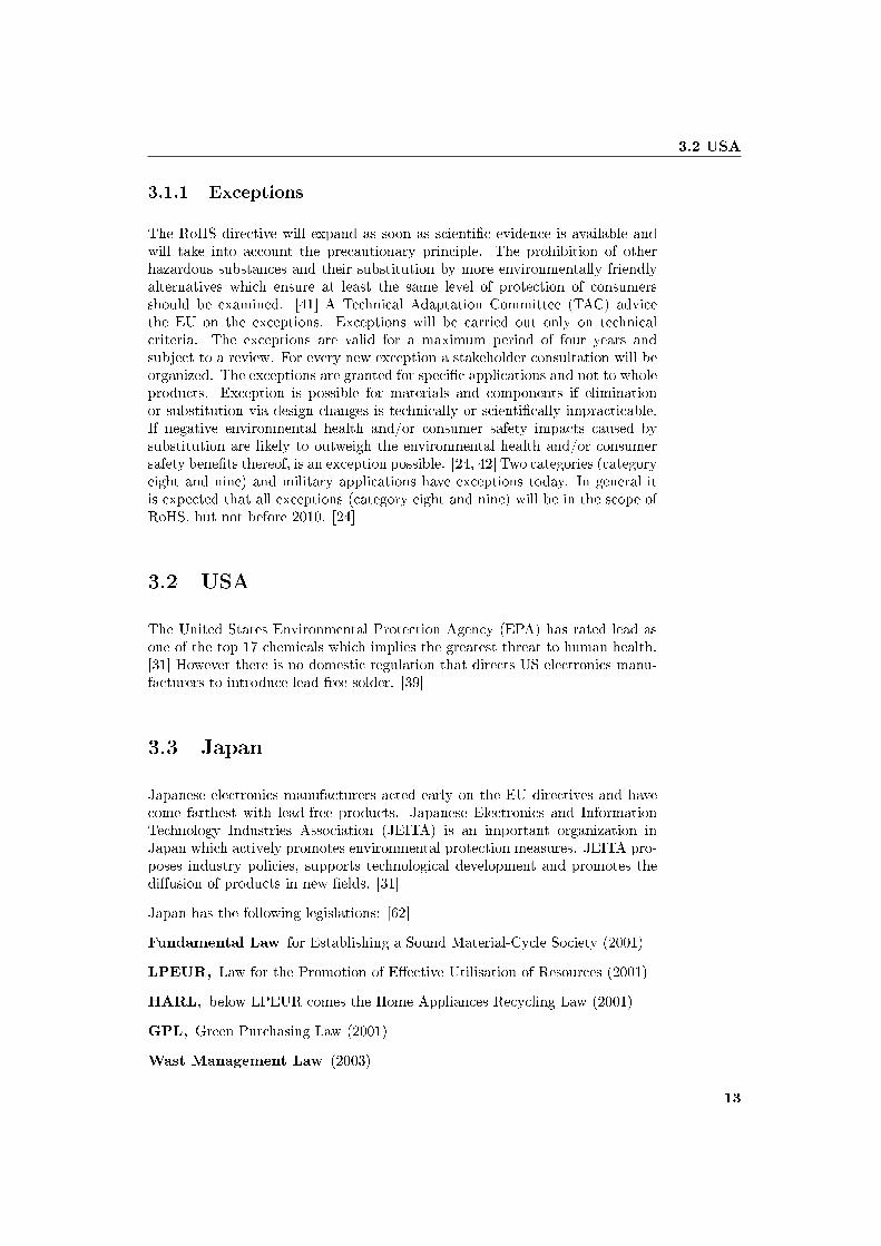
3.1.1 Exceptions
The RoHS directive will expand as soon as scienti�c evidence is available andwill take into account the precautionary principle. The prohibition of otherhazardous substances and their substitution by more environmentally friendlyalternatives which ensure at least the same level of protection of consumersshould be examined. [41] A Technical Adaptation Committee (TAC) advicethe EU on the exceptions. Exceptions will be carried out only on technicalcriteria. The exceptions are valid for a maximum period of four years andsubject to a review. For every new exception a stakeholder consultation will beorganized. The exceptions are granted for speci�c applications and not to wholeproducts. Exception is possible for materials and components if eliminationor substitution via design changes is technically or scienti�cally impracticable.If negative environmental health and/or consumer safety impacts caused bysubstitution are likely to outweigh the environmental health and/or consumersafety bene�ts thereof, is an exception possible. [24, 42] Two categories (categoryeight and nine) and military applications have exceptions today. In general itis expected that all exceptions (category eight and nine) will be in the scope ofRoHS, but not before 2010. [24]
3.2 USA
The United States Environmental Protection Agency (EPA) has rated lead asone of the top 17 chemicals which implies the greatest threat to human health.[31] However there is no domestic regulation that directs US electronics manu-facturers to introduce lead-free solder. [39]
3.3 Japan
Japanese electronics manufacturers acted early on the EU directives and havecome farthest with lead-free products. Japanese Electronics and InformationTechnology Industries Association (JEITA) is an important organization inJapan which actively promotes environmental protection measures. JEITA pro-poses industry policies, supports technological development and promotes thedi�usion of products in new �elds. [31]
Japan has the following legislations: [62]
Fundamental Law for Establishing a Sound Material-Cycle Society (2001)
LPEUR, Law for the Promotion of E�ective Utilisation of Resources (2001)
HARL, below LPEUR comes the Home Appliances Recycling Law (2001)
GPL, Green Purchasing Law (2001)
Wast Management Law (2003)
13

International legislations
Japanese RoHS (2006). The Japanese RoHS is a marking rather than re-striction law. Many Japanese companies put in place voluntary RoHSagreements in the late 90s.
3.4 China
A RoHS like law has been introduced by the Ministry of Information Industry(MII), "Management Methods for Pollution Prevention and Control in the Pro-duction of Electronic Information Products". [31] China RoHS will take e�ect inMarch 1, 2007 and control the same six substances as EU. China has publishedthree implementation standards to support China RoHS. See table 3.3 and 3.4for the three standards and the categories in the China RoHS. [43, 52]
1. The Limitation of Hazardous Substances in Electronic Products2. Testing Methods for Hazardous Substances in Electronic InformationProducts3. Marking for control of pollution caused by electronic informationproducts
Table 3.3: China implementation standards
1. Radar2. Telecom3. Broadcast and TV4. IT equipment5. Household Electronic Appliance6. Electronic Measuring Instrument7. Electronic Industry Production and Manufactring Equipment8. Electronic Component and device (including battery)9. Medical equipment10. Electric special material
Table 3.4: Categories covered by the China RoHS directive
3.5 Australia
The RoHS directive has not a�ected Australia so much, however it has implica-tions for local manufacturers. Australia's Environment Protection and HeritageCouncil (EPHC) are exploring the possibility of introducing RoHS measures.EPHC consists of state, territory and federal environment ministers. Issues as-sociated with implementing a RoHS-like scheme in Australia was discussed in
14

3.6 South Africa
October 2006 on the behalf of the EPHC. A preliminary economic and envi-ronmental assessment of the implications to implement RoHS in Australia is inprogress. [58, 59] Australia is one of Saab Systems "domestic markets" [1].
3.6 South Africa
South Africa runs the risk of being left behind, according to Eileen LeopoldCEO of South African Electrotechnical Export Council (SAEEC). Many SouthAfrican companies are unaware of the full implications of the directive and arenot taking the necessary steps to deal with them. Some initiatives have howeverbeen taken at company level and by industry associations. The SAEEC willset up a workshop to look at the implications across a�ected industry sectors.Industry needs to lobby for appropriate legislations locally and work with theexport councils to develop support programs, according to Leopold. [60, 61]South Africa is one of Saab Systems "domestic markets" [1].
15

International legislations
16

Chapter 4
Current status on lead-freesoldering
ELFNET published a lead-free soldering implementation status survey in 2006.The results of that survey were that the majority of the companies felt wellinformed. 60% of the companies are producing lead-free products, but about20% are still not active in lead-free soldering. Main problems are temperatureissues and component supply. SAC (tin-silver-copper) is clearly favoured forall types of soldering, SAC305 (3.0% silver and 0.5% copper) is the dominatingSAC solder. Alternatives to SAC solders are considered. [24] SnCu is the secondfavourite for wave and manual soldering. Solder ball and �nish materials werevaried widely. More than 80% reported that they changed technical equipmentdue to lead-free introduction, 72% are making large or moderate changes. Abig majority change or will change their assembly/component design. 60% ofthe companies would prefer a "RoHS compliant" label, only 20% opting for"Lead-Free". However less than 30% felt that labelling is necessary at all, lessthan 20% were already labelling products. About half do not intend to label atcomponent level. 60% were aware of industry standard labelling systems suchas IPC1066/JESD 97, but less than 10% were using them in practice. Aroundhalf of the respondents had been requested to supply RoHS compliant products.A majority have changed logistic system due to lead-free introduction. [23]
The industry in Sweden is for the most part prepared, 95% of the componentsare lead-free. Awareness is generally high, but some are still in a wait andsee mode. RoHS and lead-free education is an issue according to the Swedishnational network IVF. Logistics concerns are the major challenge in all Europeancountries. Availability of RoHS compliant components is one important issue,another problem is that fake lead-free components are sold in some countries.The main topic for further research is reliability aspects of lead-free solders. Inmany European countries it is expected that small assembly companies will beout of business after July 1, 2006. They can not a�ord the investments and costassociated with the transition to lead-free soldering. [24]
Japanese electronics manufacturers have worked with lead-free production fora long time and have a big lead e.g. to European countries. More than 90%
17

Current status on lead-free soldering
of the domestic electronics in Japan was expected to be lead-free by the endof 2003. [31] 73% of the Japanese companies prefer to use SAC in lead-freesoldering. [63] Japanese manufacturers should have noticed reliability problemswith lead-free soldering, because they have used it for several years now. Insome tests in China at the end of November 2006 lead-free solder joints showedvery little di�erence to lead joints. Good wetting properties but a little moregreyish solder joints were the results.
Siemens, Ericsson and Nokia were leading the development towards lead-free sol-dering around year 2000, according to Peter Back at ENICS. However it ceasedbetween the years 2002-2004. [43] Ericsson had to slow down the changing pro-cess because of the lack of lead-free components and the high cost of lead-freecomponents. When the supply increased a few years later they continued thetransition process. Some of Ericssons applications manufactured in Kista areexcepted from the RoHS directive, but some of them are produced lead-freeanyway. They do that to simplify the logistics and because of the last time buyof lead components. Ericsson has a mixed production today, but up to 90%of the components are lead-free. [16] When HP, Motorola, Microsoft and Dellstarted their work at year 2004, the pressure at the component manufacturersincreased again. During the end of year 2005 it came a new solder paste everythird week. ENICS have produced lead-free products the recent six months,they believe they have an advantage to many others because they made thetransition to lead-free soldering slowly. If the process is well controlled ENICSrecommend using lead-free soldering. It may be a little trial and error in thebeginning. The lead-free process have changed and improved a lot the last twoyears.
Peter Back at ENICS has a feeling that the reliability has decreased for consumerelectronics the recent years, which could be a possible concern for lead-freesoldering. However consumer products are not high reliability applications. Heis also concerned that most tests are not made during full capacity in the factory.The test conditions are not the same as in mass production. [43]
4.1 Current status at Saab
A working group called TTG-RoHS (Technical Transfer Group) has been startedin Saab. They are working with issues regarding the RoHS directive. Problemsregarding lead-free soldering are their main task. [12] Saab Systems is a companywith very special products in very small batches. The most of Saab Systemsapplications are excepted from the EU directives. All business units are usingelectronic equipment in their products so every department in Saab Systemswill be a�ected. Some of Saab Systems customers are demanding lead-freeapplications. It is Saab Systems opinion that it is important to discuss thetechnical consequences with using lead-free soldering, because of the uncertaintyin reliability. Saabs working team visited "Elektronikproduktionsmässan" inÄlvsjö and everyone agreed that the RoHS directive will cause a lot of work andproblems. One positive e�ect of the directive is that the communication betweenmanufacturers and designers increases according to Saab. Manufacturers believethat the problems will be solved, but investments are necessary. [5, 6, 7, 9]
18
4.1 Current status at Saab
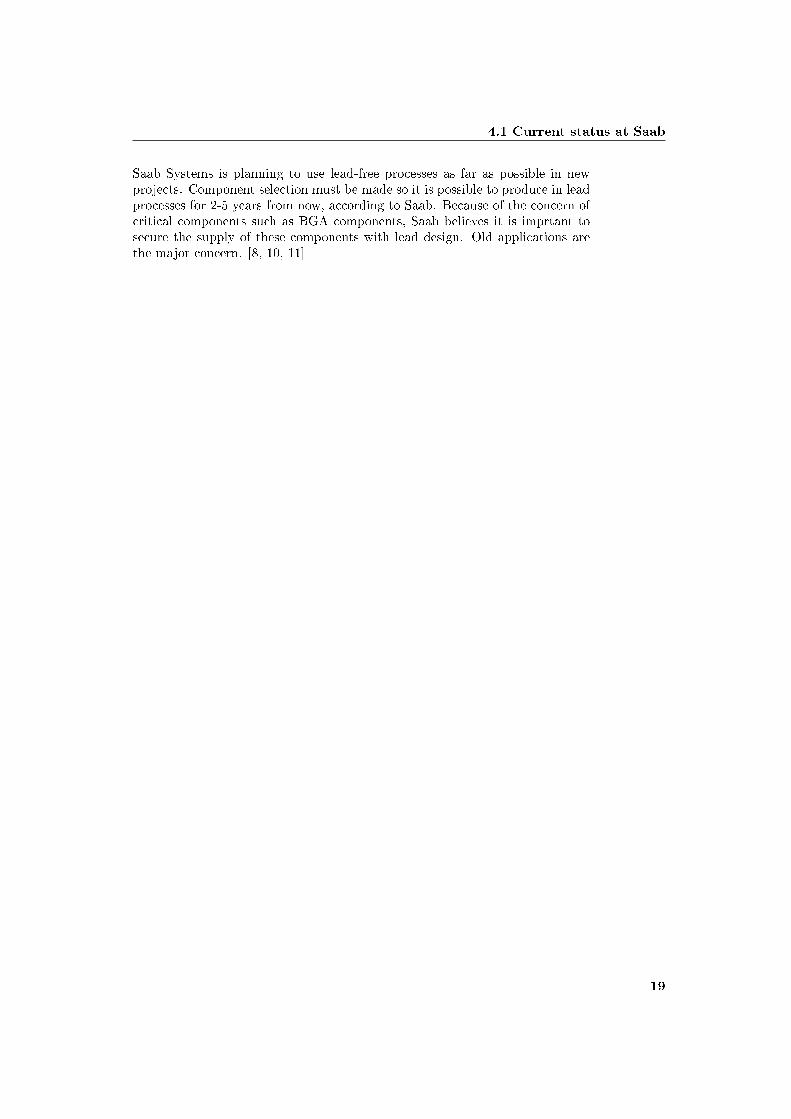
Saab Systems is planning to use lead-free processes as far as possible in newprojects. Component selection must be made so it is possible to produce in leadprocesses for 2-5 years from now, according to Saab. Because of the concern ofcritical components such as BGA components, Saab believes it is imprtant tosecure the supply of these components with lead design. Old applications arethe major concern. [8, 10, 11]
19

Current status on lead-free soldering
20

Chapter 5
Logistics
The RoHS directive is 90% about administration and logistics problems and10% about technical problems. [25]
5.1 Storage
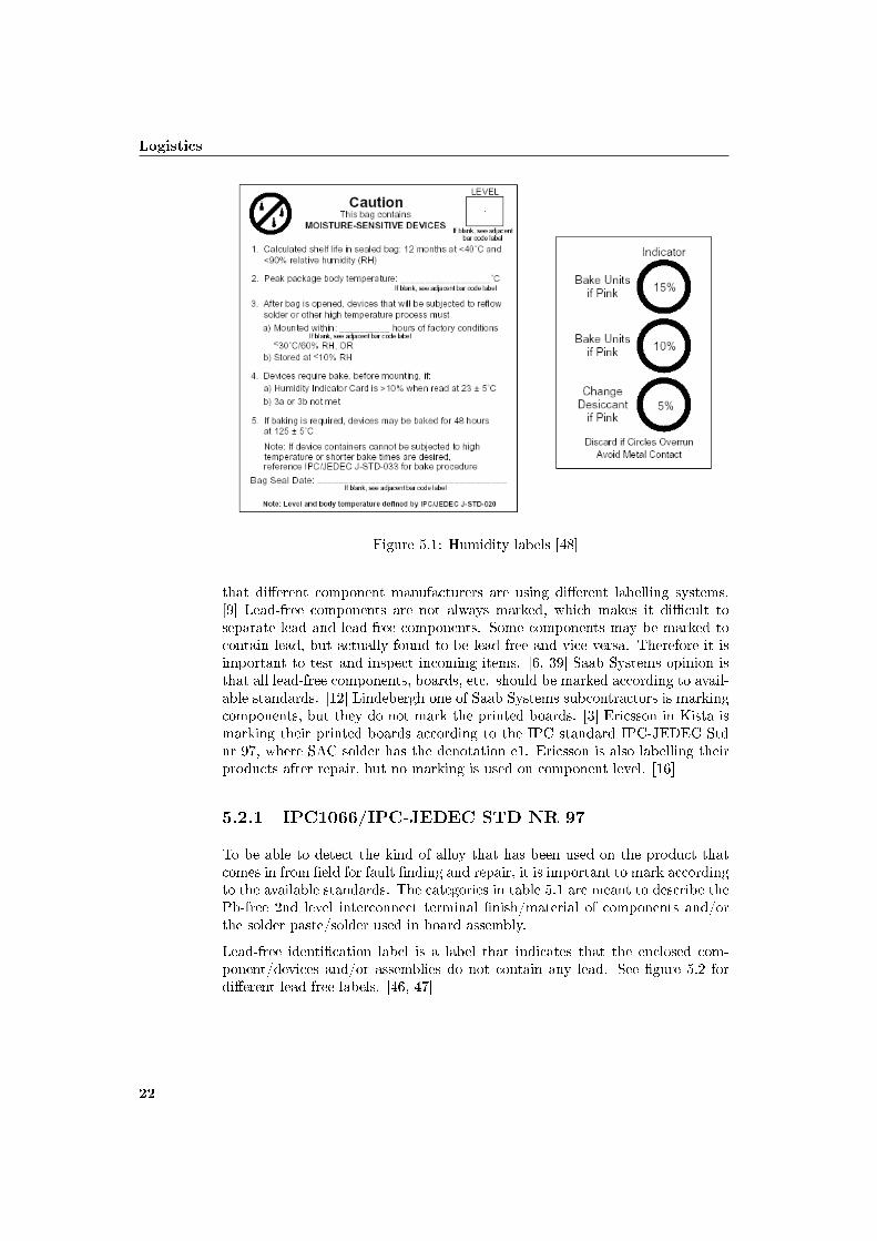
The higher solder temperature in a lead-free process makes it even more impor-tant to secure that the components have low moisture content. Moisture cancause delamination and pop corning. The risk of cracks also increase, thereforeit is crucial to follow the storage recommendations. There are no new recom-mendations, but it is even more important than before to follow the existingrecommendations (IPC-JEDEC J-STD 033A). It could be necessary to havecontrolled storage environments. Storage in a nitrogen environment could be analternative for lead-free components, which is recommended by some componentand board manufacturers. [4, 5, 6] Lead-free components and boards are consid-ered to have a shorter shelf life. Routine checks are needed so the componentsare used before the performance, etc. decreases. Today, help systems to preventthis problem exist. It is some kind of indicator that shows the time left beforethe components needs to be assembled. The recommendation for storage time,etc. from the suppliers should therefore be followed. [1, 10, 13] See �gure 5.1for humidity labels.
Saab Avitronics in Kista has a relative humidity of 15-20% in their storagefacility. The storage limit should be one year for lead-free components, but theyhave a storage time of up to �ve years. [15] It is necessary for Saab Systems todo an inventory check and separate lead and lead-free components, accordingto Saab Systems. [8, 10]
5.2 Marking
It is important to mark components and boards, this according to Conny Svens-son at Bodycote, a company making analyses for Saab. [13] One concern is
21
Logistics
Figure 5.1: Humidity labels [48]
that di�erent component manufacturers are using di�erent labelling systems.[9] Lead-free components are not always marked, which makes it di�cult toseparate lead and lead-free components. Some components may be marked tocontain lead, but actually found to be lead-free and vice versa. Therefore it isimportant to test and inspect incoming items. [6, 39] Saab Systems opinion isthat all lead-free components, boards, etc. should be marked according to avail-able standards. [12] Lindebergh one of Saab Systems subcontractors is markingcomponents, but they do not mark the printed boards. [3] Ericsson in Kista ismarking their printed boards according to the IPC standard IPC-JEDEC Stdnr 97, where SAC solder has the denotation e1. Ericsson is also labelling theirproducts after repair, but no marking is used on component level. [16]
5.2.1 IPC1066/IPC-JEDEC STD NR 97
To be able to detect the kind of alloy that has been used on the product thatcomes in from �eld for fault �nding and repair, it is important to mark accordingto the available standards. The categories in table 5.1 are meant to describe thePb-free 2nd level interconnect terminal �nish/material of components and/orthe solder paste/solder used in board assembly.
Lead-free identi�cation label is a label that indicates that the enclosed com-ponent/devices and/or assemblies do not contain any lead. See �gure 5.2 fordi�erent lead-free labels. [46, 47]
22

5.2 Marking
e1 - SnAgCu (SAC)e2 - Other Sn alloys (e.g. SnCu, SnAg, SnAgCuX, etc.) (no Bi or Zn)e3 - Sne4 - Precious metals (e.g. Ag, Au, NiPd, NiPdAu) (no Sn)e5 - SnZn, ZnX (no Bi)e6 - Contains Bie7 - Low temperature solder (< 150◦C) containing In but no Bi
Table 5.1: Solder denotation
Figure 5.2: Lead-free labels [46, 47]
23

Logistics
24

Chapter 6
Lead-free issues andalternatives
The personnel will need special training because of the transition to lead-freesoldering and the inspection methods will have to be revised and updated. [27]When the transition to a lead-free process is made, it is important to modify theproduct to be material and process compatible. It is crucial to �nd alternativesolutions and components, when direct replacements are not available. [50] Aproduct previously manufactured as non RoHS compliant, converted to RoHScompliant is changed in form, �t or function. Therefore ENICS requires thatthe part number is changed, either in version, revision or part number. [51]
6.1 Education
The personnel need to be trained so they know why they have to do thingsdi�erently and the consequences of not changing. A lot of training and se-cure routines are needed. [1, 13] A common training and a special training forassemble and repair personnel are necessary. [8, 10] The employees at SaabSystems subcontractor Lindebergh will be trained to understand the di�erencewith lead-free soldering. Everyone at Ericsson in Kista has participated in a30 minutes lead-free course. Repair personnel had a special external training.Ericsson wants everyone to know the meaning of the RoHS directive and thatit is not only lead that is banned in the RoHS directive. [16] Saab on the otherhand is considering introducing a solder certi�cate for those who are solderingRoHS applications. A green area could also be introduced in the production, toprevent mixing lead and lead-free soldering. [1, 2] Ericsson is marking lead-freeequipment and benches, but they have not separated lead and lead-free pro-duction. However in the repair area lead and lead-free work is separated. [16]Lindebergs do not have a green area, they only mark their lead-free equipment.[3]
25
Lead-free issues and alternatives
6.2 Temperature
Elevated temperatures may cause damage to circuit, components, insulations,plastic parts and delamination of circuit boards. [39] The higher melting pointa�ects every stage of the lead-free manufacturing, from assembly to the testingprocesses. [31]
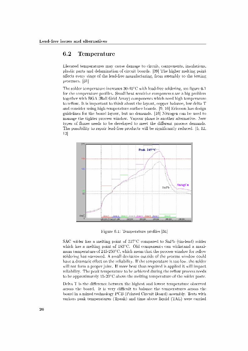
The solder temperature increases 30-40◦C with lead-free soldering, see �gure 6.1for the temperature pro�les. Small heat sensitive components are a big problemtogether with BGA (Ball Grid Array) components which need high temperatureto re�ow. It is important to think about the layout, copper balance, low delta Tand consider using high temperature surface boards. [9, 10] Ericsson has designguidelines for the board layout, but no demands. [16] Nitrogen can be used tomanage the tighter process window. Vapour phase is another alternative. Newtypes of �uxes needs to be developed to meet the di�erent process demands.The possibility to repair lead-free products will be signi�cantly reduced. [5, 12,13]
Figure 6.1: Temperature pro�les [31]
SAC solder has a melting point of 217◦C compared to SnPb (tin-lead) solderwhich has a melting point of 183◦C. Old components can withstand a maxi-mum temperature of 245-250◦C, which mean that the process window for re�owsoldering has narrowed. A small deviation outside of the process window couldhave a dramatic e�ect on the reliability. If the temperature is too low, the solderwill not form a proper joint. If more heat than required is applied it will impactreliability. The peak temperature to be achieved during the re�ow process needsto be approximately 15-20◦C above the melting temperature of the solder paste.
Delta T is the di�erence between the highest and lowest temperature observedacross the board. It is very di�cult to balance the temperatures across theboard in a mixed technology PCB (Printed Circuit Board) assembly. Tests withvarious peak temperatures (Tpeak) and time above liquid (TAL) were carried
26

6.2 Temperature
out with QFP (Quad Flat Pack) and BGA components. The BGA componentsin this test had lead-free solder bumps, the other components had pure tin �nishon the leads. In some combinations, the solder paste did not even melt. Evenif time above liquid increased, lower peak temperature produced incompletere�ow. Higher peak temperatures and increased time above liquids producedvery dull solder joints. Higher temperatures (240◦C) and lower time aboveliquids (25 sec.) produced shiny joints. See table 6.1 for the results of the visualinspection of the joints at di�erent TAL and Tpeak.
Run Set Tpeak Set TAL Visual inspection of joints1 225 25 Incomplete re�ow2 225 50 Incomplete re�ow3 225 95 Incomplete re�ow4 225 125 Incomplete re�ow5 240 25 Shiny joints6 240 50 Less shiny joints7 240 95 Dull joints8 240 125 Dull joints9 255 25 Shiny joints10 255 50 Less shiny joints11 255 95 Dull joints12 255 125 Dull joints
Control 246 64 Less shiny joints
Table 6.1: Visual inspection results
This phenomenon could be attributed to the �ux and the transformation itundergoes due to the higher temperature. Passive components of all sizes showedgood solder joints. Solder wicking was observed during visual inspection of thesolder joint for some combinations. If too much wicking occurs, there will not beenough solder left in the pad to form a good solder joint. It could also damagethe component. The peak temperature has a major role in the amount of solderwicking. When time above liquids and peak temperature are speci�ed outsidethe solder paste manufacturer speci�cations, it in�uences the strength of thesolder joint. A lead-free process is less forgiving, pro�ling revealed higher deltaT across the PCB. However, no physical damage was noticed to the passiveor active components by moving the peak temperature and time above liquidsoutside the process window. The e�ect of deviation from the process windowon the fatigue life of the solder joints should be investigated. [19]
The peak temperature during re�ow has to reach at least 240◦C, compared to220◦C for SnPb solder. The process window in re�ow decreases from 30-40◦Cfor SnPb to 20-25◦C for SAC solder. Total wetting on the PCB could be atrisk. Tighter process window is a result of the need to minimize the uppertemperature to avoid damage on sensitive components. The recommendation isto extend the time above liquid instead. The higher process temperature meansthat IR ovens will probably not be able to manufacture good quality solderjoints on complex PCBs. IR ovens have larger temperature di�erence betweendi�erent components on the board. It is strongly recommended when solderingwith SAC solder to build the temperature pro�le in the oven according to the
27
Lead-free issues and alternatives
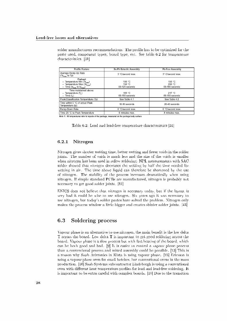
solder manufacturers recommendations. The pro�le has to be optimized for thepaste used, component types, board type, etc. See table 6.2 for temperaturecharacteristics. [31]
Table 6.2: Lead and lead-free temperature characteristics [31]
6.2.1 Nitrogen
Nitrogen gives shorter wetting time, better wetting and fewer voids in the solderjoints. The number of voids is much less and the size of the voids is smallerwhen nitrogen has been used in re�ow soldering. NPL measurements with SACsolder showed that nitrogen decreases the wetting by half the time needed forwetting in air. The time above liquid can therefore be shortened by the useof nitrogen. The stability of the process increases dramatically when usingnitrogen. If simple standard PCBs are manufactured, nitrogen is probably notnecessary to get good solder joints. [31]
ENICS does not believe that nitrogen is necessary today, but if the layout isvery bad it could be wise to use nitrogen. Six years ago it was necessary touse nitrogen, but today's solder pastes have solved the problem. Nitrogen onlymakes the process window a little bigger and creates shinier solder joints. [43]
6.3 Soldering process
Vapour phase is an alternative to use nitrogen, the main bene�t is the low deltaT across the board. Low delta T is important to get good soldering across theboard. Vapour phase is a slow process but with fast heating of the board, whichcan be both good and bad. [9] It is easier to control a vapour phase processthan a conventional process and mixed assembly could be possible. [13] This isa reason why Saab Avitronics in Kista is using vapour phase. [15] Ericsson isusing a vapour phase oven for small batches, but conventional ovens in the massproduction. [16] Saab Systems subcontractor Lindebergh is using a conventionaloven with di�erent heat temperature pro�les for lead and lead-free soldering. Itis important to be extra careful with complex boards. [10] Due to the transition
28

6.4 Solder
to lead-free soldering Ericsson replaced old equipment that could not reach themaximum temperature of 235◦C in ten seconds. [16]
The recommendations are to use a solder bath temperature between 250-260◦C,with 250◦C as an absolute minimum. A Norwegian lead-free project showsacceptable or good results at 250, 255 and 260◦C for SnCu and SAC alloys. [31]
6.4 Solder
The industry has studied a wide range of alloys to replace the SnPb alloy dur-ing the last decade. The selection of a new alloy is based on a number ofconsiderations; toxicity, melting temperature, surface tension, wetting ability,mechanical properties, electrochemical properties, cost, etc. The candidates forwave soldering are SAC, SnAg (tin-silver) and SnCu (tin-copper). CurrentlySAC alloy for re�ow and SAC or Sn0,7Cu for wave soldering are the favourites.The general belief is that SAC alloys with a silver content of 3.0-4.0% are allacceptable compositions. Studies by IPC, solder suppliers and electronic man-ufacturing companies show that there is no signi�cant di�erence in the processperformance and thermo mechanical reliability for these alloy compositions. [27,31] Ericsson follows these recommendations and allows SAC alloys in these in-tervals. The SAC alloy is used for the entire board, they allow SAC, SnAg,SnCu and SnCuNi (tin-copper-nickel) in wave soldering and selective soldering.[16]
SAC alloys outperform the SnCu alloy in terms of wetting ability and reliability.SnCu has a much lower cost than SAC and that makes it an attractive alterna-tive alloy for wave soldering. Most manufacturers prefer to use the same alloyfor the entire board. Some volume production use SAC for re�ow soldering andSnCu for wave soldering on the same board. In those cases, methods for inspec-tion and rework must be compatible with both alloys. SAC and SnCu are thelead-free solder alloy choice for the most of the worldwide electronic industry.[27] Manufacturers in Asia are using SAC for high reliability applications andsome other alloys for consumer goods. [13]
6.4.1 Tin-silver-copper
There are two recommendations, one by iNEMI (International Electronics Man-ufacturing Initiative) SAC396 (for re�ow) and one by JEITA SAC305 (for re�ow,wave solder and hand solder). Japanese electronics companies will start to useSAC305 and is therefore more interesting. [63] NEMI has proposed and testedSAC396 for re�ow soldering and SnCu for wave soldering. [22] SAC is the mostpopular replacement to SnPb solder. SAC tested solder alloys with Ag between3-4% and Cu between 0.5-1.5% are recommended. The concerns with this alloyfamily are higher processing temperatures, leaching of silver from the solder intoland�lls and metals cost 2.5 times that of SnPb eutectic. [31]
Assembly of 160 PCBs at IVF printed with SAC solder paste did not show anysigni�cant di�erence compared to assembling on SnPb paste. One hour betweenprinting and mounting gave no visible decrease in assembly quality. Lead-free
29
Lead-free issues and alternatives
solders have higher surface tension than SnPb solder, however the solderabilityis not as good for SAC and the time above liquid has to be longer to give a goodre�ow. Components self centre almost as well in SAC solder according to testsperformed by NPL. [31]
Tests made by NOTE shows good thermal cycling and mechanical stress withSAC305. It is less sensitive for lead contamination than the other alternativesand is recommended by several manufacturers. Asian manufacturers are in-creasing their use of SAC305. The melting point is 30◦C above SnPb solder,the wetting ability is not as good as for SnPb. [13] NOTE recommend a SACsolder process. [29] Toshiba and Hitachi are using SAC396. [22] Mitsubishi isusing some kind of SAC solder. [53] Lindebergh is also using SAC (SAC387).[3]
6.4.2 Tin-silver-copper-bismuth/Tin-silver-bismuth
The advantages of SACB (tin-silver-copper-bismuth) compared to SAC are alower melting point and better wetting ability. The disadvantages are that toomuch bismuth decreases the mechanical properties and problems with lift-o�in printed hole assembly. It is also very sensitive to lead contamination. [29]The SnAgBi (tin-silver-bismuth) alloy is a candidate for SMT (Surface MountTechnology) applications. One big concern with bismuth are �llet lifting thatoccurs in SnPb through hole applications, toxicity and low melting phase. Otherconcerns are lack of compatibility with lead bearing �nishes, leaching of silverinto land�lls, metals cost 2.5 times that of SnPb eutectic. [31]
6.4.3 Tin-zinc
SnZn (tin-zinc) has a lower melting temperature (200◦C), a thin melting areaand lower metals cost. The concerns are oxidation of zinc, long term corrosionof the �nished soldering joint, which requires special �ux and wetting that isnot as good as with SAC. It is used for the toy industry. [29, 31]
6.4.4 Tin-copper
The SnCu alloy is a low cost alternative for wave soldering, it is compatible withmost lead bearing �nishes. Process considerations must be taken because of thehigh melting temperature (227◦C). The mechanical properties are not as goodas for SnPb. Metals cost 1.5 times that of SnPb eutectic. [29, 31] It is used byMatsushita. [22] SnCu is recommended by iNEMI as wave solder and also byJEITA (their second choice for wave solder).
6.4.5 Tin-silver
The SnAg alloy has a little higher melting temperature (221◦C) than SAC andsimilar cost to SAC. SnAg has been used for years in special applications. [31]SnAg is recommended by JEITA as re�ow solder (their second choice). [63]
30
6.5 Components
6.5 Components
The peak temperature required for components for lead-free soldering is 260◦C.The actual component body temperature may be di�erent from the tempera-ture measured on the board, because of component thermal characteristics andlocations on the board. The IPC/JEDEC standard J-STD-020-C speci�es thata lead-free component shall be capable of being reworked at 260◦C within eighthours of removal from dry storage or bake. Soldering temperatures and tol-erances are captured in the standard. [27] Ericsson make demands on theircomponent suppliers that they should follow the IPC/JEDEC standard J-STD-020-C, to secure that the components can withstand the higher temperature.[16]
6.5.1 Supply
Saab believes that the supply of lead components will stop. They are concernedthat big electronic manufacturers will make end of life (EoL) purchases, whichwill make it hard to get lead components. Most component manufacturers meanthat the supply of lead-free components will not be a problem, but the supplyof old components will be a problem. [5, 6] It is important to secure the supplyon critical components such as BGA. [10, 11]
6.6 Printed surface boards
The higher process temperature has to be considered before the printed boardselection. Common sti� boards as FR4 (Flame Resistant 4) will not be moreseriously a�ected in wave soldering compared to SnPb, because of the shortexposure time to the molten solder on the wave side. For re�ow soldering thereis an increased risk of bending the board which can cause fall o� of componentsin the second re�ow cycle in double sided mounting. [31] The surface boardsonly manage 4-5 re�ow cycles in lead-free soldering, after the �rst repair threeor four of the available cycles are used. [43] Alternative board selection mustbe considered if several re�ow soldering processes are applied. One solution isto use a support in the middle of the board, but this requires component freeareas where the support contacts the board. Higher Tg laminates is anotheralternative. [31]
According to Saabs working team, common FR4 is not appropriate in lead-freesoldering, because of the high temperature. [6] For complex multilayer boards,common FR4 will probably not be a good alternative. For each re�ow processthe board is a�ected negatively. An alternative to common FR4 is HTg FR4which has a 190◦C Tg compared to 130◦C for common FR4. 370HR is an HTgboard type which should manage six re�ow soldering processes. [9] Ericsson isstill using common FR4 boards. They made demands on their suppliers that theprinted boards should withstand six re�ow cycles. Their suppliers could onlyguarantee four re�ow cycles. Ericsson is therefore investigating if they need tostart using high temperature printed boards. They believe it is important to
31
Lead-free issues and alternatives
make demands on the suppliers regarding which temperature and how manyre�ow cycles the board should withstand. [16]
6.7 Flux
Attempts to mix no-clean �ux (developed for SnPb) with lead-free solder alloysgave catastrophic results. The higher temperature for lead-free solders requiresgreater stability of the �ux at higher temperatures. Water-soluble �uxes forlead-free solder paste and wave soldering applications will also be needed. [27]To improve the wetting properties, development of the �ux chemistry is a keyissue. [31]
6.8 Surface �nishes
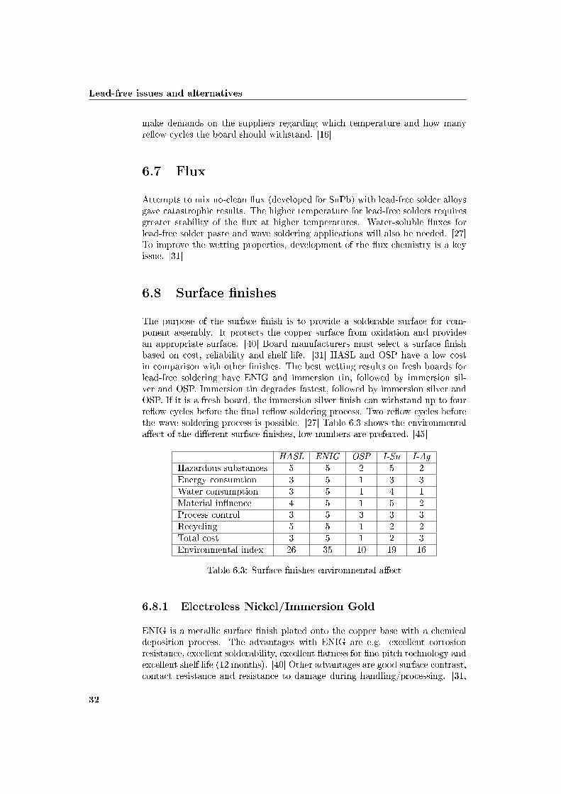
The purpose of the surface �nish is to provide a solderable surface for com-ponent assembly. It protects the copper surface from oxidation and providesan appropriate surface. [40] Board manufacturers must select a surface �nishbased on cost, reliability and shelf life. [31] HASL and OSP have a low costin comparison with other �nishes. The best wetting results on fresh boards forlead-free soldering have ENIG and immersion tin, followed by immersion sil-ver and OSP. Immersion tin degrades fastest, followed by immersion silver andOSP. If it is a fresh board, the immersion silver �nish can withstand up to fourre�ow cycles before the �nal re�ow soldering process. Two re�ow cycles beforethe wave soldering process is possible. [27] Table 6.3 shows the environmentala�ect of the di�erent surface �nishes, low numbers are preferred. [45]
HASL ENIG OSP I-Sn I-AgHazardous substances 5 5 2 5 2Energy consumtion 3 5 1 3 3Water consumption 3 5 1 4 1Material in�uence 4 5 1 5 2Process control 3 5 3 3 3Recycling 5 5 1 2 2Total cost 3 5 1 2 3Environmental index 26 35 10 19 16
Table 6.3: Surface �nishes environmental a�ect
6.8.1 Electroless Nickel/Immersion Gold
ENIG is a metallic surface �nish plated onto the copper base with a chemicaldeposition process. The advantages with ENIG are e.g. excellent corrosionresistance, excellent solderability, excellent �atness for �ne-pitch technology andexcellent shelf life (12 months). [40] Other advantages are good surface contrast,contact resistance and resistance to damage during handling/processing. [31,
32

6.8 Surface �nishes
40] The disadvantages are a more narrow process window, black pads, highcost process (1.5-2 times higher than HASL) and fatigue failures on large BGApackages. [28, 40]
ENIG provides good solderability and contact interfaces for most applications.It provides a more reliable surface �nish, but is in general more brittle thanjoints between tin and copper. After storage and heat exposure ENIG �nishesstill have excellent wetting. Tight plating process control is necessary to avoid"black pad" failures. Black pad is due to oxidation of the nickel layer duringthe immersion gold process. It can lead to catastrophic failures due to theseparation of the solder from the pad. [27] ENIG is the predominant surface�nish in Japan and the EU. [28]
6.8.2 Immersion silver
I-Ag is a co-deposit of silver and organics. The advantages are excellent sol-derability, excellent for �ne pitch and BGAs technologies, very good alternativeto HASL and similar cost. It also has a good shelf life (6-12 months). [28, 40]Immersion silver is a less costly alternative, but the solderability and contactpad performance are not as good as ENIG. It is after all an adequate surface�nish for most applications. However handling and storage needs to be carefullycontrolled. [27]
A test made by Sandia National Laboratories investigated the e�ects of storageenvironments on the solderability of immersion silver board �nishes. SAC396was used with solder temperatures of 245 and 260◦C. Contact angle less than50◦ have predicted the successful use of lead-free solders on printed wiring as-semblies. The contact angles values were generally lower and the wetting ratesgenerally faster at the higher solder temperature. There was a signi�cant dropin wetting rate after 6 and 9 months. Figure 6.2 shows the storage e�ect onI-Ag board �nishes. A process temperature of 245◦C is preferred in case ofre�ow soldering. The SAC solder would maintain a su�cient solderability overthat temperature for a shelf life of 12 months. If the �nish were stored for120 months acceptable solderability was predicted. Poor solderability could beexpected between 12 and 120 months. It is therefore preferred to avoid agingtimes beyond 12 months. SnPb solder would maintain su�cient solderabilityon immersion silver for aging periods of up to 24 months.
Steam aging did not have a signi�cant e�ect on the wetting rate fore a soldertemperature of 260◦C. It did a�ect the wetting rate of SAC solder tested at245◦C after aging of 16 months. The wetting rate rebounded after 24 months.The contact angle and wetting rate showed that the solderability of the im-mersion silver was insensitive to steam aging. Only one exception, a signi�cantdecrease of wetting rate was found after 16 months. When the solder tempera-ture was increased to 260◦C the contact angle increased to 17◦. The conclusionwas that steam aging is not appropriate for predicting the solderability storagelife of immersion silver for either SnPb or SAC solders. [20]
33

Lead-free issues and alternatives
Figure 6.2: Storage e�ect [20]
6.8.3 Hot Air Solder Levelling
HASL is a molten solder immersion and hot air levelling of surfaces and holesto provide a "tinned" coating on exposed copper surfaces. The advantages areexcellent solderability, one of the less expensive surface �nishes and good shelflife. [40] The thickness and solderability of HASL is di�cult to control. [27]HASL has a minimal use in Japan. [28] HASL is ENICS �rst choice, but someclients demand ENIG. [43]
6.8.4 Organic Solderability Preservative
OSP is water based organic compound that protects the copper during soldering.The advantages are that gold does not need to be protected and it is reworkable.[40] OSPs are cheaper than SnPb and contain no lead. It is easily processableand smoother than HASL. [31] The major disadvantage is that it is di�cult orimpossible to inspect the �nal product. [40] Other concerns are short storage life,high soldering temperature, solderability and �ux chemistry. The solderabilityis more easily degraded by multiple re�ows. OSP has been used for manyyears and provides a �at pad surface. OSP is commonly used, a high volumealternative because of the low cost. [27, 28, 31] OSP with lead-free soldering isnot a good alternative according to ENICS. [43]
6.8.5 Immersion tin
I-Sn is a co-deposit of tin and organics. One advantage is that it is reworkable.[40] I-Sn is commonly used in the EU. It has good solderability with SAC alloys.Good shelf life (6-12 months). However pure tin electroplating represents a riskin high reliability applications. [1, 28]
34
6.9 Inspection
6.9 Inspection
SAC solder joint has a more greyish and matte appearance when compared toa SnPb solder joint. SAC solder does not spread as well on the pad as SnPbsolder, which may result in a changed standard footprint on PWBs. The mattesurface makes it harder for the human eye as well as for a robot to detect non-conformity in a solder joint. Instructions for operations have to be revised andAOI (Automatic Optical Inspection) robots have to be reprogrammed. [13, 27]
6.10 Rework and repair
A great concern is rework and repair due to the higher temperatures needed tocreate a good solder joint. Rework has for lead-free solders been found moredi�cult, due to di�erence in wetting ability. There are higher demands onrepair robots and hand soldering stations for lead-free soldering. It is importantto create a temperature pro�le that is similar to the one used in the re�ow oven.Caution is required to make sure that components do not exceed their maximumtemperature. X-ray inspection should be performed on each reworked BGA-225.It is easy to lift pads during hand soldering, because of the high temperaturerequired (371◦C). Skilled personnel have reported that hand soldering withlead-free solders need more time than ordinary SnPb. Successful methods havebeen developed for many types of components. Rework and repair of area arraypackages is a great concern. It is helpful to use a rework system with split visionand temperature pro�ling. [27, 31, 32]
Ericsson is recommending using controlled hot air, where a programmed temper-ature pro�le decides the soldering temperature. Non controlled hot air, wherethe distance between the solder point and the hand held nozzle is decided bythe operator, should only be used if surrounding components are protected fromheat. There are cases when it is better to scrap the board instead of trying torepair it. [16, 38]
35

Lead-free issues and alternatives
36
Chapter 7
Reliability of lead-freesoldering
One great concern with lead-free soldering is that no long term reliability testsor experiences from lead-free soldering is available. [6] An investigation of thereliability and function of COTS (Commercial O� The Shelf) product shouldtherefore be carried out, according to Saab. This uncertainty is the reason whythe defence industry has an exception according to Saab. [10, 11] However,Conny Svensson at Bodycote believes that the reliability of lead-free productsis good enough even for Saab Systems high reliability demands. He believes itis more important to look at quality aspects than to only focus on the reliabilityissues. [12, 13, 25]
LEAB has been given the information in their cooperation with IVF that lead-free solder joints are harder but more brittle. If the solder joint is exposed tothermal cycling or vibration, the joint becomes "weaker". [15] Jan-Eric Spjuthproduction engineering manager at Saab Avitronics, believes that lead-free ap-plications can have a problem with fast temperature changes. [4]
A great concern is that the reliability of most lead-free solders has not beenestablished for high reliability applications. High reliability users have littlecontrol over the direction of the overall industry. Only 1% of the total electronicsmarket is aerospace applications. Military and aerospace users are in a positionwhere they need data to help them understand to what grade lead-free solderswill perform di�erently from SnPb solders.
Three types of lead-free solders were used in tests by JCAA/JG, SAC396, SACB(Sn3.4Ag1.0Cu3.3Bi) and SnCu (Sn0,7Cu). Eutectic SnPb was used as referencefor all testing. The SAC alloy was used for re�ow, wave and hand soldering.SACB was used for re�ow and hand soldering, SnCu was used for wave andhand soldering. The recommended �ux of each solder manufacturer was used.A rosin-based (ROL1 and RMA) �ux vehicle was used for lead-free re�ow. Forlead-free wave soldering a volatile organic compound (VOC, a no clean �ux)was used. The component types used were e.g. BGA, TQFP (Thin Quad FlatPack) and CSP (Chip Scale Package). Six component surface �nishes were used;
37

Reliability of lead-free soldering
SnPb, SAC, SACB, NiPdAu (nickel-palladium-gold), SnCu and Sn. [32]
The high tin lead-free solders with silver, copper, tin and bismuth shows similarreliability to SnPb solders. During high temperature and strain ranges, SnPbsolders tend to have a higher fatigue life than the lead-free solders. During lowtemperature and strain ranges, lead-free solders have up to double the fatiguelevel of the SnPb alloys. [31]
7.1 Reliability testing
Considerable work around the world is currently being undertaken to generatereliability data on lead-free soldering systems. SnPb based alloys have 60 yearsof reliability experience. The following tests were made by JCAA/JG, NPL andSMTA.
7.1.1 Vibration
The test results from JCAA/JG suggest that for some component types, lead-free solders are as reliable as SnPb solder. With some component types thelead-free solders failed before the SnPb solder. However this does not meanthat lead-free solders can not be used in high performance electronics. It meansthat models for calculating the actual �eld lifetime of lead-free solder jointsneeds to be developed and validated by using actual vibration test data. Thesemodels can be used to verify that lead-free solders will survive for the requiredlifetime in the �eld.
Tests with BGA-225 showed that the combination SnPb solder with SnPb ballsalways outperform lead-free solder with SAC balls. The combination SnPbsolder with SnPb balls outperformed the combinations of lead-free solder withSnPb balls and SnPb solder with SAC balls. For reworked components SnPbgenerally outperformed lead-free solders. Contamination of lead-free solderswith lead gave mixed results. [32]
7.1.2 Mechanical shock
The SnPb and SAC soldered assemblies did not have any failures in mechanicalshock tests. Failure analysis concluded that SnPb and lead-free solder jointssurvived high stress levels. The failures occurred were not related to the sol-der joints. The solder joints survived the functional test for �ight equipment,functional test for ground equipment and crash hazard test for ground equip-ment test levels. The failures at higher test levels were attributed to connectorfailures or failures at the board traces. [32]
7.1.3 Thermal shock
The thermal shock test exposed the components to 1000 cycles of -55 to +125◦C.Most of the components did not fail this test. Generally, mixing SnPb and lead-
38
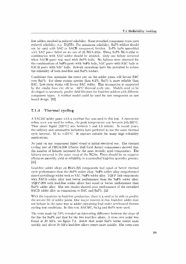
7.1 Reliability testing
free solders resulted in reduced reliability. Some reworked component types gavereduced reliability, e.g. TQFPs. For maximum reliability, SnPb solders shouldnot be used with SAC or SACB component �nishes. SnPb balls assembledwith SAC paste failed on six out of 25 BGA-225s. Using SnPb BGA-225s incombination with SAC solder should be avoided. Only one failure occurredwhen SACB paste was used with SnPb balls. No failures were observed forthe combinations of SnPb paste with SnPb balls, SAC paste with SAC balls orSACB paste with SAC balls. Rework operations have the potential to reducethe reliability of both lead-free and SnPb solders.
Conditions that minimize the stress put on the solder joints will favour SACover SnPb. For shear strains greater than 6.2%, SnPb is more reliable thanSAC. Less shear strain will favour SAC solder. This assumption is supportedby the results from the -20 to +80◦C thermal cycle test. Models need to bedeveloped to accurately predict �eld lifetimes for lead-free solders with di�erentcomponent types. A veri�ed model could be used for any component on anyboard design. [32]
7.1.4 Thermal cycling
A SAC387 solder paste with a no-clean �ux was used in this test. A convectionre�ow oven was used for re�ow, the peak temperature was between 245-260◦C.Time above liquid (220◦C) was between 1 and 1.5 minute. In recent years,the military and automotive industries have preferred to use the same thermalcycle interval, -55 to +125◦C. It appears suitable for many high reliabilityapplications.
No joint on any component failed visual or initial electrical test. The thermalcycling test of PBGA-256 (Plastic Ball Grid Array) components showed thatthe number of failures increased for the most severely aged components. Thefailures occurred in the outer rings of the BGAs. There should be no negativee�ects on assembly yield or reliability in a controlled lead-free assembly process.[35]
Lead-free solder alloys on BGA-225 components had equal or better thermalcycle performance than the SnPb solder alloy. SnPb solder alloy outperformedmixed metallurgy solder such as SAC/SnPb solder alloy. TQFP-144 componentswith SACB solder alloy had better performance than the SnPb solder alloy.TQFP-208 with lead-free solder alloys had equal or better performance thanSnPb solder alloy. The test results showed poor performance of the reworkedSACB solder alloy in comparison to SAC and SnPb. [32]
With the transition to lead-free production, there is a need to be able to predictthe service life of solder joints. One major concern is that lead-free solder doesnot behave in the same way as solder containing lead under accelerated thermocycling test conditions. In this test, SAC387, SnAg and SnPb were used.
The tests made by NPL revealed an interesting di�erence between the slope ofthe line for SnPb and that for the two lead-free alloys. A cross-over point wasfound at 20 MPa, see �gure 7.1. Below that point SnPb solder creeps morequickly and above 20 MPa lead-free alloys creeps more quickly. The creep rate
39

Reliability of lead-free soldering
increase faster at higher temperatures for SnPb, because of the lower meltingpoint. Creep measurements taken at 50 and 80◦C showed faster creep ratesfor SnPb with stress levels between 15 and 25 MPa. The creep measurementsfrom NPL �t well with data observed at other laboratories. The calculations ofacceleration factors and the temperature test pro�les needs to be modi�ed tomatch �eld conditions. [33]
Figure 7.1: Cross-over point [33]
The assembly industry often estimates the long-term reliability by assessing thelife-time of the solder joints. The solder joint is known to be the weakest linkin the assembly. This study focused on some problems highlighted by the UKindustry. The alloys studied were SAC and SnAg, they were compared with theSnPbAg alloy. Two surface �nishes, ENIG and immersion silver were used, withthe substrate material FR4. Re�ow was investigated, with one and two passesor one re�ow and one wave process. PBGA and QFP components were some ofthe components used in the test. Thermal cycling between -55 to +125◦C wasused. The ramp rate of 10◦C per minute is a moderate ramp, slower than athermal shock test, which has a ramp rate of 30◦C per minute. Shear testing isa destructive method for evaluating the degree of crack spreading and damageto the solder joint after thermal cycling. It is assumed that a crack in the solderjoint will limit the strength of the joint.
A comparison between the data for joints soldered with SnAg and SAC showedthat SnAg gave poor performance for R1206 resistors and PBGA on ENIG�nished boards. Di�erent heat-treatments have little e�ect on the reliability forBGA component joints with ENIG boards and SnAg alloy. The reliability ofBGA joints using SAC were better than those using SnPbAg alloy. SAC solderjoints also outperformed joints made using SnAg.
For lower values of strain joints, SAC is preferred and SnPbAg alloy is betterfor the higher strain ranges. There is a cross-over in reliability performancebetween joints made with lead-free and SnPb alloys. The tests indicate that
40

7.1 Reliability testing
the PCB �nish has no e�ect on the shear strength values. Failures of the platedthrough hole were unexpected and there could be a possible concern with vias.Failures began after 500 thermal cycles.
The tests by NPL also revealed a 50% reduction in shear force when a crackhas grown signi�cantly. The shear strength changes most during the �rst 500to 1000 cycles, when the �rst 50% of the crack develops. [34] Figure 7.2 showsa failure mode after thermal cycling.
Figure 7.2: Failure after thermal cycling [63]
7.1.5 Combined environments
This test investigated if quartz crystal products can sustain higher re�ow tem-peratures and a variety of harsh operating environments. Product failures areoften caused by the following environmental stresses, mechanical shock, vibra-tion, thermal shock, humidity, temperature cycling and corrosion. Productsintroduced into the �eld are characterized by three stages; early life, useful lifeand wear out (See �gure 7.3). The purpose of environmental life tests is to sortout the early life failures and provide a feedback mechanism.
The stabilization bake test was used to determine the e�ect on device storageat elevated temperature. The components were placed into an environmentalchamber in 24 hours of dwell time at 150◦C. No failures were found in elec-trical tests. Temperature cycling is used to determine the resistance of a partto extreme high and low temperatures. The components were exposed to 200cycles of -65 to +125◦C for 100 consecutive hours. Each extreme temperaturewas held for �fteen minutes, time between extreme temperatures was less than�ve minutes. No failures were found in electrical tests. The samples were alsoinspected under a microscope, no evidence of physical damage or degradationwas found. Thermal shock tests are also used to determine the resistance of apart to extreme high and low temperatures. The product could experience this
41

Reliability of lead-free soldering
Figure 7.3: Failure regions [21]
when transferred to and from heated shelters in artic areas. The same extremetemperatures as in the temperature cycling test were used. The componentswere exposed to a two hours and 45 minutes pro�le running at �ve 15 min-utes cycles, with a transfer time of less than 60 seconds between temperatureextremes. No failures were found in electrical tests.
The random vibration test was used to determine the ability of the device towithstand the dynamic stress caused by random vibration. Upper and lowerfrequency limits were 20-2000 Hz to simulate the vibration experienced in var-ious �eld environments. No failures were found in electrical tests. The sweepsine vibration test is used to determine the e�ect of high frequency vibration oncomponent parts in the frequency range of 10-2000 Hz. No failures were foundin electrical tests.
Constant accelerating tests are used to determine the e�ects on the types ofstructural and mechanical weaknesses not necessarily detected in vibration tests.The test progressed up to the maximum capability of the centrifuge, a totalacceleration of 8000 g's for �ve minutes was achieved with no failures. Veri�ca-tions testing showed no failures either. Shear test results showed shear strengthnumbers high enough to sustain numerous environmental stresses. It is withhigh probability that the selected product group is capable of meeting RoHSrequirements and sustaining a wide variety of harsh operating environments.[21]
The tests made by JCAA/JG showed that the solder alloy had a major e�ect onsolder joint reliability. SAC soldered components were less reliable than SnPbsoldered components. Components with SACB solder were more reliable thanthe SnPb soldered components, with the exception of SnPb BGA-225 compo-nents. Reworked components failed more often, the exception was the reworkedBGA-225 components. The hot air rework station could have exposed the BGAcomponents to hotter temperatures than they experienced during the re�ow sol-
42

7.1 Reliability testing
der process. The higher temperatures could have provided better solder melting.Contamination of SnPb in SAC soldered BGA-225 appears to degrade the reli-ability. [32]
7.1.6 Salt fog
SAC, SACB and SnCu solder joints reliability are the same as for SnPb solderjoints. [32]
7.1.7 Humidity
SAC, SACB and SnCu solder joints reliability are the same as for SnPb solderjoints. [32]
7.1.8 Test summary
Results from individual tests alone should not be used to make de�nite de-cisions on lead-free reliability. The component type has the biggest e�ect onsolder joint reliability performance for thermal cycling and combined environ-ment. Component location on the board has a signi�cant e�ect on solder jointreliability performance in a vibration environment. When mixed solders wereused for BGA-225 components, early failures occurred in thermal shock. Lead-free solders have the same reliability as SnPb solders for some component typesand environments. Unfortunately for some other component types and envi-ronments, the lead-free solders failed before the SnPb solder. SAC solderedcomponents were at least as reliable as the SnPb solder for thermal cyclingbetween -20 to +80◦C. During thermal cycling between -55 to +125◦C, vibra-tion and combined environment tests showed that SAC solders were often lessreliable.
Lead-free solder joints shown lower reliability in some tests. However that doesnot necessarily mean that lead-free solder alloys can not be used in aerospaceand defence electronics. Models for calculating the actual �eld lifetime must bedeveloped and validated using actual test data. More testing must be done todetermine the e�ect of higher re�ow temperatures on printed wiring boards andfunctional integrated circuits. Lead contamination must be better understoodif the SACB solder is to be used. If lead contamination is not controllable, thatmay rule out the use of SACB solders on some or all aerospace and defenceelectronics. See table 7.1 for test results. CET is an abbreviation for CombinedEnvironment Tests. All comparisons are based on �rst failure numbers. Datawithin 5% of the baseline is denoted with a 0. Single symbols, - or +, denotedata that is 5% to 20% above or below the baseline. Double symbols, - - or ++,denote data that is more than 20% above or below the baseline. [32]
43
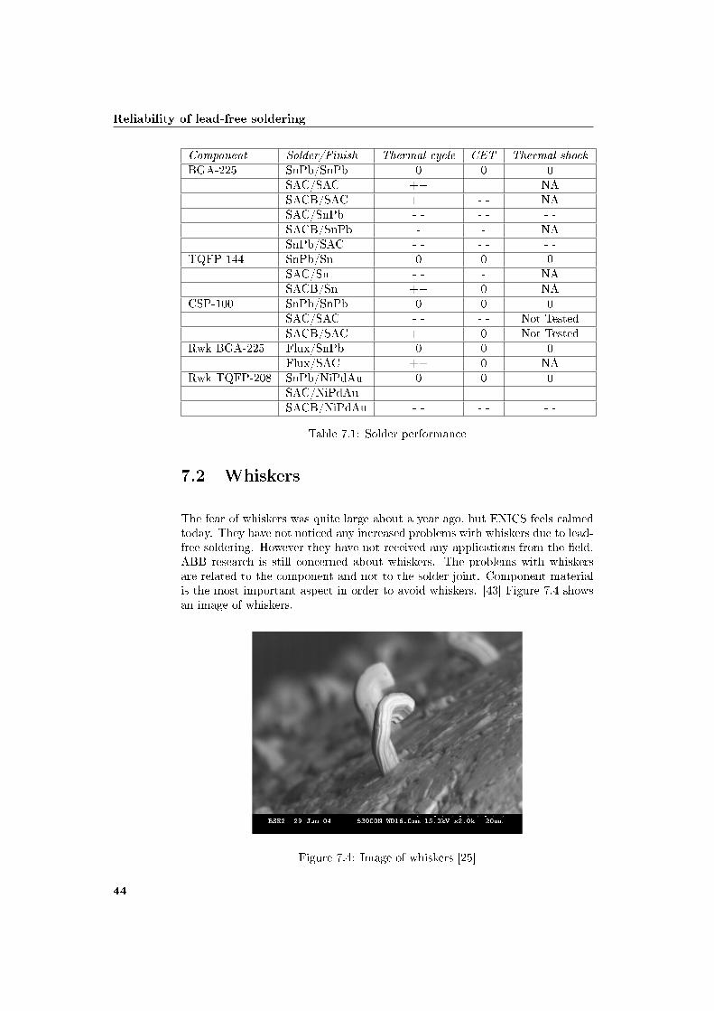
Reliability of lead-free soldering
Component Solder/Finish Thermal cycle CET Thermal shockBGA-225 SnPb/SnPb 0 0 0
SAC/SAC ++ - - NASACB/SAC ++ - - NASAC/SnPb - - - - - -SACB/SnPb - - NASnPb/SAC - - - - - -
TQFP-144 SnPb/Sn 0 0 0SAC/Sn - - - NASACB/Sn ++ 0 NA
CSP-100 SnPb/SnPb 0 0 0SAC/SAC - - - - Not TestedSACB/SAC ++ 0 Not Tested
Rwk BGA-225 Flux/SnPb 0 0 0Flux/SAC ++ 0 NA
Rwk TQFP-208 SnPb/NiPdAu 0 0 0SAC/NiPdAu - - - - - -SACB/NiPdAu - - - - - -
Table 7.1: Solder performance
7.2 Whiskers
The fear of whiskers was quite large about a year ago, but ENICS feels calmedtoday. They have not noticed any increased problems with whiskers due to lead-free soldering. However they have not received any applications from the �eld.ABB research is still concerned about whiskers. The problems with whiskersare related to the component and not to the solder joint. Component materialis the most important aspect in order to avoid whiskers. [43] Figure 7.4 showsan image of whiskers.
Figure 7.4: Image of whiskers [25]
44

7.3 Voids
In the past, pure tin was used to solder electronic components. It was commonlyused because it is corrosion resistant. It was discovered that the use of pure tinin electronic components could create tin whiskers. Tin whiskers are singlecrystals which emerge from tin-�nished surfaces. Whiskers could be a seriousreliability risk, causing electrical shorting in tightly spaced electronic circuitry.Lead has been used for a long time, which resulted in many incident free yearsaccording to a report from the Department of the Air Force in the USA. NASA'spolicy states, "Pure tin plating is prohibited as a �nal �nish on EEE partsand associated hardware", because of the reliability risks with whiskers. TheDepartment of Defence and NASA believe that the use and the risk of tin�nish on electronic components will increase. This is because the commercialindustry will eliminate lead from electronics. Defence and aerospace industryshows increasing usage of commercial components. The reduction in circuitgeometry and power means that even small whiskers may cause catastrophicfailures. [39]
In the beginning it was Saabs opinion that tin whiskers could grow faster withlead-free soldering. Higher levels of tin were believed to cause problems, buttests showed no problems. Most likely the problem is not bigger now thanbefore. According to the board manufacturers the problem with tin whiskers isexaggerated. [5, 6] Ericsson reported no increased problems with whiskers dueto the transition to lead-free soldering. It is impossible to accelerate whiskers,which makes it hard to know if it is a bigger problem. Risks can be decreased byusing matte tin and surface �nishes. Some are using bismuth, but Ericsson doesnot use it because other problems occur. [16] None of the whiskers observed byJCAA/JG violated the minimum electrical spacing dimensions. [32]
7.3 Voids
Increased voiding levels associated with the higher temperatures have been re-ported. The general belief in the industry is that the change to lead-free solder-ing will increase voiding levels with a reduction in solder joint reliability. Muchinformation indicates a connection between voiding, soldering and reliability ofthe joints assembled with SnPb solders. The possibility of a similar connec-tion for joints produced with lead-free solders has been investigated. Figure 7.5shows optical and microscope images of voids in lead-free balls after re�ow.
A 6-layer FR4 multilayer of thickness 1.6 mm was used and the surface �nishwas ENIG. The component type was PBGA-256 with SAC balls. Three di�erentre�ow pro�les with seven solder pastes were used. Six of the pastes were ano-clean �ux, the seventh was a water soluble paste. Pastes A and B wereprocessed on PCBs, which had been aged by passing them through a lead-freere�ow pro�le two or four times before the assembly process. After the assemblyprocess, voiding levels were measured using an X-ray system. For the BGAs, anAOI was utilized, which calculates the total area of voids in each PBGA solderjoint. The thermal pro�le used was -55 to +125◦C.
The e�ect on reliability of smaller voids is complicated and depends on wherethe voids are located within the joint. Voids have been shown to have a direct
45

Reliability of lead-free soldering
Figure 7.5: Optical and electron microscope images of voids [64]
e�ect on reliability. One report showed no reduction in reliability of PBGA withup to 24% voiding by area, and an improvement in reliability with voiding levelsup to 16%. The improvement in reliability with limited voids could be a resultof some or all of these following three suggestions. Voids may be acting as crack"catcher". The structure becomes more �exible. Voids increase the height ofthe solder joints, which reduce the stress.
All failures occurred close to the edge of the die in the component. The voidinglevels were all well below the 25% maximum voiding level speci�ed by the IPCstandard A610. Aging the PCB before the assembly process had little e�ect onthe voiding levels. Surface mount assembly with lead-free solder processed undera wide range of conditions has not produced high levels of voiding. Average valueof voiding were 2-4%, individual values reached 13%. The IPC 7095 guidelinesfor class 3 BGAs call for a maximum voiding level of 9%. The results suggestthat if the IPC maximum voiding levels are followed, there will be no negativee�ect from voiding on the reliability of lead-free solder joints. This robustnessof the lead-free technology will be welcomed by manufacturers and end users.They could feel reassured that high voiding levels with lead-free solder pasteswill not take place. [36]
7.4 Brittle fractures
Brittle fracturing in solder joints is a rare cause of failure. Some investigationsindicate that lead-free soldering will increase the risk of brittle fractures. Rea-sons are a higher elastic modulus and thicker and more complex intermetalliclayers may form when lead-free solders are used. Brittle fractures are caused bybending of assemblies, which can occur during assembly, testing and shipping.Mechanical shock, e.g. dropping the product to the ground, fast temperaturechanges and vibration are other causes of fractures. Dropping a product to theground is likely the most common cause of brittle fractures. Large BGA compo-nents are more inclined to brittle fractures. They are most vulnerable directlyafter soldering. BGA components need to be handled carefully during soldering,testing and shipping in order to avoid bending. The fractures take place in the
46

7.5 Mixed assembly
layer of intermetallic compound (IMC), but it is necessary for achieving a reli-able solder joint. The IMC layer is formed at the solder/metal interface duringsoldering and it is usually hard and brittle. Solder joints with SAC solders toboth OSP and ENIG pads are much more brittle than those with SnPb solders.Figure 7.6 shows a corner solder joint to a PBGA after soldering. The crack hasmost likely been caused during the cooling phase in the soldering process or bybending of the board after soldering. [30]
Figure 7.6: Image of a crack in a solder joint [30]
7.5 Mixed assembly
Mixed assembly is one of the major problems with lead-free soldering, accordingto Lars-Gunnar Klang. Figure 7.3 shows some combination of materials andtheir failure energy. The solder alloy KOKI is SnAgCuNiIn. [63]
SMT has no problems with lead contamination, however mixed assembly is notpossible in wave soldering because of the lead contamination. [1] Mixed assemblyis generally hard, especially with BGA components. [13] Lead-free componentscan generally be assembled in a lead process, BGA and CSP components maynot be assembled in a mixed process. Lead components can generally not beassembled in a lead-free process, because of lead contamination and the highsoldering temperature. [5, 6]
BGA components are not backward or forward compatible according to Erics-son. Ericsson received lead-free BGA components without asking for it in oneproject. They had to use a "reballing" process, to change the solder balls tolead. A repair process was used after a while instead of the reballing process.There is a risk in mixing lead and lead-free solders, BGA components with leadsolder balls can cause voids in a lead process. Ericsson does not recommendmixed assembly, but it is not a requirement. Di�erent SAC alloys can be mixedaccording to Ericsson. [16]
47

Reliability of lead-free soldering
Figure 7.7: Combination of material [63]
48
7.5 Mixed assembly
7.5.1 Metallurgical imbalance
How serious could the metallurgical imbalance be? A practical example, SAC396system for both the BGA solder balls and the solder paste is used. Assume thePWB (Printed Wiring Board) plating is tin matte, leaving a �nal metallurgyessentially the same as the original solder ball and solder ball percentages ofSn3.86Ag0.6Cu. The same technician now replace the BGA, this time the tech-nician uses 96.5Sn3.5Ag, a common lead-free solder paste. The new metallur-gical imbalance will be Sn3.85Ag0.53Cu, a radical metallurgical change. Thisdemonstrates how easy it is to create an unintentional metallurgical imbalancecondition, which can a�ect long term reliability in the �eld. [22]
7.5.2 Contamination
This study determined if either lead contamination of SAC soldered joints orlead-free surface �nish contamination SnPb solder joints, presents any issueswith solder joint reliability. Tin plated QFP components soldered with SACpaste revealed some reliability issues. None of the other combinations showedany failures. The other combinations were components with SnPb solder andlead contaminated solder or SnPb components with either SnPb or SAC solder.BGA components also showed failures during the 2000 thermal cycles. Thefailures were close to the edge of the silicon die.
SAC solder in BGA joints provides better fatigue resistance than SnPb solder.Small levels of lead contamination can be tolerated. There are no indicationsthat lead contamination of well formed joints has any e�ect on low cycle fatigueresistance. [37]
7.5.3 Compatibility
Compatibility concerns can arise if lead-free components have to be attachedwith SnPb solders. One study investigated various combinations of lead �nishes,solder types and pad �nishes, in order to understand the e�ect of aging on thesolder joint pull strength for a 0.5 mm QFP. Joints formed by attaching lead-free �nishes with a SnPb solder were studied. The board pad �nish was ENIG,I-Ag and I-Sn, component lead �nishes Sn, SnCu or SnBi. The pull strengthsfor mixed solder and pure SnPb solder assemblies decrease with aging. For purelead-free joints the e�ect of aging is negligible after 350 hours. Until 350 hoursof aging, SnPb assembly has higher pull strength than pure lead-free. Lead-freeassembly has higher pull strength than mixed assembly. ENIG pad �nish in apure lead-free assembly shows higher pull strength than in mixed assembly. [17]
Forward compatibility refers to current components with SnPb balls and lead-free solder. Backward compatibility refers to lead-free components with SnPbsolder. Area array packages, e.g. CSP and BGA with SAC balls are not con-sidered to be backward compatible with SnPb solder.
Under conditions of 0-100◦C, area array assemblies using SnPb balls with SACsolder appear less reliable than SnPb assembly. Backward compatibility tests
49

Reliability of lead-free soldering
with area array assemblies shows the same level of reliability, when the peakre�ow temperature is above 225◦C. But with SnPb pro�les with a peak tem-perature of 205-225◦C, quality and reliability concerns arise. [27]
50
Chapter 8
Discussion
This chapter discusses the six research questions and then follows some criticismof the chosen methodology.
8.1 What legislations are there
The EU, Japan, California and China are closed markets for exporters of compo-nents contining lead. Korea will be closed later this year. Taiwan and Australiaare working with their directives. South Africa has just started its process andneeds to speed up their work.
The RoHS directive is the cause of lead-free soldering and a debate about theenvironmental e�ect of the directive can be read on the internet and di�erentforums. The debate is easily spread into the company. However it is not mean-ingful to discuss, the directive is here and now the companies will have to learnto live with it. Wait and see is not a very good solution, the directive is alreadyin action. Everyone needs to speed up their work so the transition to lead-freesoldering goes without any major complications. The exception in the directivewill probably be withdrawn and when that happens it is crucial to be ready.
8.2 Status on lead-free soldering
The ELFNET status survey shows that the majority of the companies are wellinformed, but 20% are still not active in lead-free soldering. The Swedish indus-try is for the most part prepared and 95% of the components are lead-free. TheTTG-RoHS group at Saab is working with issues regarding the RoHS directive.The main problems are temperature issues and logistics, according to the statussurvey. It is clear that changing technical equipment is necessary. The lack oflabelling according to available standards shows the need of further information.Why lead-free products needs to be marked must be clear. The status surveyalso shows that SAC solder is favoured for all types of soldering.
51
Discussion
Japanese electronics manufacturers have worked with lead-free production fora long time, more than 90% of the domestic electronics in Japan was expectedto be lead-free by the end of year 2003. Therefore they should have noticed ifthere were any serious reliability problems with lead-free soldering. However ifthey are not producing any lead-free high reliability applications, there couldstill be problems for the military industry.
8.3 Impact on logistics and administration
The transition to lead-free soldering will have a major a�ect on logistics andadministration, because the RoHS directive is 90% about administration andlogistics problems. Lead and lead-free components must be separated, newpart numbers for lead-free components, etc. Only 10% is technical problems.Therefore it is important for Saab Systems to control if a new logistic system isnecessary when lead-free soldering is introduced. It will probably be necessaryto change the logistic system, the status survey made by ELFNET support thisconclusion.
Moisture can cause delamination and pop corning, therefore it is very importantto have proper storage environments. Controlled storage environment couldbe necessary for Saab Systems and their subcontractors. Routine checks andindicators are necessary to avoid that too old components are assembled. It isimportant to do an inventory check and maybe have separate inventories forlead and lead-free components.
Humidity labels and lead-free labels are important to avoid mixing lead and lead-free components and to secure that the components can be assembled withoutcomplications. It is also very important to inspect incoming items because ofthe risk of false marking. The labels are also needed for fault �nding and re-pair, otherwise it is di�cult to know the terminal �nish/material of componentsand/or the solder/paste used in the board assembly.
8.4 A�ect on the solder process
Several alternatives to the SnPb solder have been studied by the industry. Theselection must be based on a number of considerations; toxicity, melting tem-perature, surface tension, wetting ability, mechanical properties, cost, etc.
Advantages and disadvantages for each solder that were investigated are listedbelow to get a good overview. The investigated solders in this thesis are SAC,SACB/SnAgBi, SnZn, SnCu and SnAg.
52

8.4 A�ect on the solder process
Table 8.1 shows the advantages, disadvantages and users of SAC. It is recom-mended by JEITA for re�ow, wave solder and hand solder.
Advantages Disadvantages UsersHigher surface tensionthan SnPb
Higher processing temper-ature
Toshiba
Less sensitive to lead con-tamination than other al-ternatives
Leaching of silver Hitachi
Outperforms SnCu interms of wetting abilityand reliability
Metals cost 2.5 timeshigher than SnPb
Mitsubishi
Wetting ability is not asgood as for SnPb
Lindebergh
Table 8.1: SAC
Table 8.2 shows the advantages, disadvantages and users of SACB/SnAgBi.
Advantages Disadvantages UsersLower melting point thanSAC
Too much bismuth coulddecrease the mechanicalproperties
Better wetting abilitythan SAC
Problems with lift-o�
Sensitive to lead contami-nationToxicityMetals cost 2.5 timeshigher than SnPb
Table 8.2: SACB/SnAgBi
Table 8.3 shows the advantages, disadvantages and users of SnZn.
Advantages Disadvantages UsersLow melting point Oxidation of zinc Used by the toy industryLower metals cost Long term corrosion
Wetting is not as good aswith SAC
Table 8.3: SnZn
53

Discussion
Table 8.4 shows the advantages, disadvantages and users of SnCu. It is recom-mended by iNEMI and JEITA as wave solder.
Advantages Disadvantages UsersLow cost alternative forwave soldering
High melting temperature Matsushita
Mechanical properties arenot as good as for SnPb
Table 8.4: SnCu
Table 8.5 shows the advantages, disadvantages and users of SnAg. It is recom-mended by JEITA as re�ow solder
Advantages Disadvantages UsersSlightly higher meltingpoint than SAC
Used for years in specialapplications
Similar cost to SAC
Table 8.5: SnAg
Table 8.6: Solder comparison
When looking at the advantages and disadvantages for these solder alloys, SACsolder seems to be the obvious choice for highly reliable applications like SaabSystems. At this moment SAC is the lead-free alternative with increasing usage.The recommended SAC alloys are between 3-4% silver and 0.5-1.5% copper.
Table 8.6 shows a comparison between �ve solder alloys. Green (+) colour rep-resents a good value, yellow (0) represents a medium value and red (-) representsa bad value (white is unknown). The table shows a comparison made betweenthe di�erent solders and the limits between green, yellow and red are arbitrary.It is made with the information in this thesis. However it gives a good picture ofthe relative performance of the di�erent solders. The low cost alternative solderSnCu is clearly not as good as the other in terms of temperature and wetting.SnCu which is used in toy manufacturing has wetting problems. SAC shouldbe preferred over SACB/SnAgBi if there is a risk for contamination. SACBshould probably be ruled out as solder for all aerospace and defence electronicsbecause of the risks for lead contamination. If the cost is not a problem, SACshould be used. If excellent wetting is not that important SnZn should be used.Saab Systems should use SAC, this theory is supported by the fact that SAC isfavoured in many countries around the world (Chapter 4 and 6.4).
54
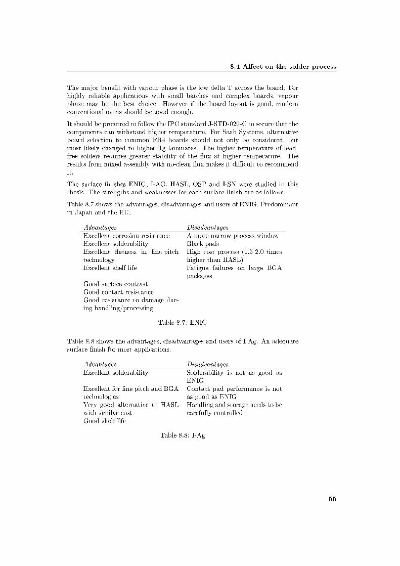
8.4 A�ect on the solder process
The major bene�t with vapour phase is the low delta T across the board. Forhighly reliable applications with small batches and complex boards, vapourphase may be the best choice. However if the board layout is good, modernconventional ovens should be good enough.
It should be preferred to follow the IPC standard J-STD-020-C to secure that thecomponents can withstand higher temperature. For Saab Systems, alternativeboard selection to common FR4 boards should not only be considered, butmost likely changed to higher Tg laminates. The higher temperature of lead-free solders requires greater stability of the �ux at higher temperature. Theresults from mixed assembly with no-clean �ux makes it di�cult to recommendit.
The surface �nishes ENIG, I-AG, HASL, OSP and I-SN were studied in thisthesis. The strengths and weaknesses for each surface �nish are as follows.
Table 8.7 shows the advantages, disadvantages and users of ENIG. Predominantin Japan and the EU.
Advantages DisadvantagesExcellent corrosion resistance A more narrow process windowExcellent solderability Black padsExcellent �atness in �ne-pitchtechnology
High cost process (1.5-2.0 timeshigher than HASL)
Excellent shelf life Fatigue failures on large BGApackages
Good surface contrastGood contact resistanceGood resistance to damage dur-ing handling/processing
Table 8.7: ENIG
Table 8.8 shows the advantages, disadvantages and users of I-Ag. An adequatesurface �nish for most applications.
Advantages DisadvantagesExcellent solderability Solderability is not as good as
ENIGExcellent for �ne pitch and BGAtechnologies
Contact pad performance is notas good as ENIG
Very good alternative to HASLwith similar cost
Handling and storage needs to becarefully controlled
Good shelf life
Table 8.8: I-Ag
55
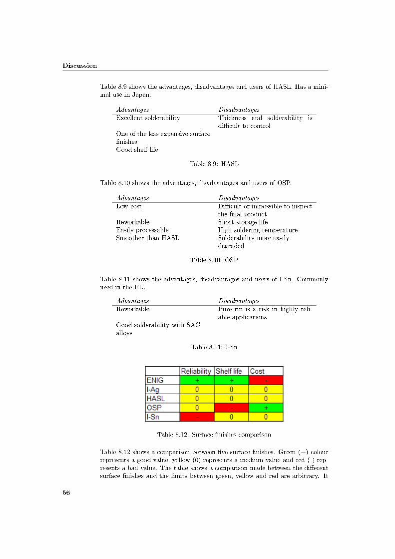
Discussion
Table 8.9 shows the advantages, disadvantages and users of HASL. Has a mini-mal use in Japan.
Advantages DisadvantagesExcellent solderability Thickness and solderability is
di�cult to controlOne of the less expensive surface�nishesGood shelf life
Table 8.9: HASL
Table 8.10 shows the advantages, disadvantages and users of OSP.
Advantages DisadvantagesLow cost Di�cult or impossible to inspect
the �nal productReworkable Short storage lifeEasily processable High soldering temperatureSmoother than HASL Solderability more easily
degraded
Table 8.10: OSP
Table 8.11 shows the advantages, disadvantages and users of I-Sn. Commonlyused in the EU.
Advantages DisadvantagesReworkable Pure tin is a risk in highly reli-
able applicationsGood solderability with SACalloys
Table 8.11: I-Sn
Table 8.12: Surface �nishes comparison
Table 8.12 shows a comparison between �ve surface �nishes. Green (+) colourrepresents a good value, yellow (0) represents a medium value and red (-) rep-resents a bad value. The table shows a comparison made between the di�erentsurface �nishes and the limits between green, yellow and red are arbitrary. It
56

8.5 A�ects of the increased solder temperature
is made with the information in this thesis. However it gives a good picture ofthe relative performance of the di�erent surface �nishes.
Table 8.12 shows that ENIG has the best reliability and shelf life performance,but the highest cost. I-Ag and HASL have similar cost and performance. I-Agis an adequate surface �nish for most applications. OSP could be an alternativeif the short shelf life is not a problem. It is a low cost alternative which shouldbe a good choice for less reliable applications. I-Sn is a risk in highly reliableapplications because of the pure tin. ENIG and I-Sn have the best wettingresults. The recommendation for Saab Systems has to be ENIG. It is not aclean or an environmental friendly process but it has the best performance.
8.5 A�ects of the increased solder temperature
The higher melting point a�ects every stage of the lead-free PCB manufac-turing, assembly and testing process. Elevated temperature causes damage tocircuits and components. Saab Systems personnel will need special trainingbecause of the transition to lead-free soldering. Inspection methods will haveto be revised and updated because lead-free solder joints have a more greyishand matte appearance. Instructions have to be revised and robots have to bereprogrammed.
Another great concern is the problems with rework and repair. Rework is moredi�cult due to the di�erence in wetting ability. Therefore the demands arehigher on repair robots and hand soldering stations for lead-free soldering.
8.6 Is it safe to use lead-free soldering for highly
reliable applications?
The major concern for highly reliable applications are that there are not enoughdata to understand to what grade lead-free solders will perform di�erently fromSnPb solders. Indications that the test conditions are not the same as duringfull capacity in the factory are also concerning. It is important to rememberthat individual tests alone should not be used to make de�nite decisions onlead-free reliability.
It was not possible to do any tests at Saab Systems. Five di�erent types ofreliability testing were studied in this thesis.
Vibration: The tests showed that SnPb outperformed lead-free solders.
Mechanical shock: Neither SnPb or SAC soldered assemblies had any failuresin mechanical shock tests.
Thermal shock: Mixed assembly gave reduced reliability. Conditions thatminimize the stress put on the solder joint will favour SAC over SnPb,however SnPb is favoured for higher shear strains.
57

Discussion
Thermal cycling: Lead-free solders showed equal or better thermal cycle per-formance than SnPb solders.
Combined environments: Quartz crystal products showed no electrical fail-ures. Tests made by JCAA/JG showed that SAC soldered componentswere less reliable than SnPb soldered components.
Component type and component location are two important factors for thesolder joint reliability. Table 8.13 shows that BGA components soldered withSAC have problems in the combined environment tests. However the lowerreliability for lead-free solders in some tests does not necessarily mean thatlead-free solders can not be used in highly reliable applications, like defenceelectronics. Models for calculating the actual �eld life time must be developedand validated using actual test data. More testing must be done to determinethe e�ect of higher re�ow temperatures.
Component Solder/Finish Thermal cycle CETBGA-225 SnPb/SnPb 0 0
SAC/SAC ++ - -SACB/SAC ++ - -SAC/SnPb - - - -SACB/SnPb - -SnPb/SAC - - - -
TQFP-144 SnPb/Sn 0 0SAC/Sn - - -SACB/Sn ++ 0
CSP-100 SnPb/SnPb 0 0SAC/SAC - - - -SACB/SAC ++ 0
Rwk BGA-225 Flux/SnPb 0 0Flux/SAC ++ 0
Rwk TQFP-208 SnPb/NiPdAu 0 0SAC/NiPdAu - - - -SACB/NiPdAu - - - -
Table 8.13: Solder performance
The whisker problems are related to the component and not to the solder joint.Component material is the most important aspect to avoid whiskers. No in-creased problems with whiskers due to lead-free soldering have been noticed.
Increased voiding levels associated with the higher temperatures have been re-ported. The general belief in the industry is that the change to lead-free sol-dering will increase voiding levels with a reduction in solder joint reliability.However investigations shows that the industry could feel reassured that highvoiding levels with lead-free solder pastes will not take place.
Brittle fracturing in solder joints is a rare cause of failure. Some investigationsindicate that lead-free soldering will increase the risk of brittle fractures.
Mixed assembly is generally hard, especially with BGA components. It is notpossible in wave soldering because of the lead contamination. However mixed
58

8.7 Criticism of chosen methodology
assembly is possible with SMT, because it has no problems with lead contami-nation. Small levels of lead contamination can be tolerated.
Compatibility concerns can arise if lead-free components have to be attachedwith SnPb solders. This is a very important area and Saab Systems has to knowif components, surface boards, solders, �ux and surface �nishes are compatibleto get the best performance. Reliability can otherwise be at risk. It is shownin chapter 7.5 (�gure 7.3) that the combination of ENIG and SAC could be abad mixture and therefore I-Ag and SAC could be a good alternative for highlyreliable applications.
Japan has used lead-free soldering for quite a long time now and they should havenoticed if there were any critical problems with lead-free soldering. However it isnot known if they only are using lead-free soldering in less reliable applications.There are no indications that lead-free soldering not should be safe to use inless reliable applications. This thesis investigates if it is safe to use lead-freesoldering in highly reliable applications. That question is not as easy and it isdi�cult to say, yes it will work without any problems or, no it is not possible touse lead-free soldering in highly reliable applications. Almost every journal, testreport and other sources is establishing that more research is needed. The majorfocus has been on the solder joint so far, but other areas also need attention.The most important thing should be to use more actual �eld data and to besure that the test conditions are exactly the same as during full capacity in thefactories.
It is important to know which environment the application will be in. If it is nota highly vibrating and thermal cycling environment, lead-free soldering shouldbe safe to use. If a lead-free soldering process is used, the process should be wellcontrolled. SAC solder, ENIG surface �nish, high Tg laminates and availablestandards should be followed to minimize the risk of failures. Compatibilityconcerns must also be taken seriously.
8.7 Criticism of chosen methodology
This chapter starts with a description of how the work was carried out duringthis thesis.
The �rst natural step was to make a current status analysis on lead-free solder-ing. The internal network, company reports and interviews with Saab personnelwere used to make this analysis. This helped getting a picture of Saab Systemsconcerns about lead-free soldering and what areas that needed to be investi-gated. After that it was interesting to know the lead-free soldering status in theEuropean Union. This was done by searching information on ELFNET and byinterviews with ELFNET representatives at Saab and IVF. This was followedup by contacts with some large enterprises in Sweden. Ericsson and ABB werecontacted, however ABB could not provide much information. This resulted ina meeting with several employees at Ericsson in Kista. ABB referred to ENICS,a subcontractor in Malmö and a meeting in Malmö was arranged.
Next step was to divide the problem areas into small groups, logistic problems,
59
Discussion
lead-free alternatives and reliability issues.
Storage and marking were the logistic problems focused on in chapter �ve.Chapter six starts with training, because it is important that the personnel knowwhy they have to change their working methods. Not changing the workingmethods can have a negative e�ect according to the sources. Interviews andliterature were used to investigate the logistic problems.
Temperature issues are also described in chapter six and the whole lead-freeprocess is described from solder process to rework and repair.
One major concern is the reliability of lead-free applications, which chapterseven is about. Chapter seven starts with some reliability tests and continueswith some problems which can a�ect the reliability. Some of the sources wereNPL, SMTA and JCAA/JG reports.
Criticism
More interviews and visiting more companies instead of searching for researchmaterial could have been done. The results would probably been the sameanyway. However a mix between interviews and research material seemed to bethe best approach. The focus in this thesis could have been di�erent, howeverthis focus is relevant to Saab Systems. The areas that are not covered or fullystudied by this thesis need to be further investigated. These areas are alsorelevant and important to Saab Systems and they are futher discussed in chapternine.
8.7.1 Sources of error
Lead-free soldering is a subject which is well debated and the economic conse-quences are considerable. Therefore it is important to re�ect on who has writtenthe report and which institute or company is behind the material. Many peoplehave their own agenda and they are not objective in their judgements. Howeverit is very di�cult to analyse the objectivity of the di�erent sources.
Data can be di�erent depending on interpretations by the investigator in aqualitative study. This case study has used data from interviews and thereforethe possible sources of errors are discussed here. Sources of errors in an intervieware the respondent, instruments and the interviewer.
Respondent
The answer to a question is dependent on when it is asked and therefore di�er-ent answers could be given to the same question at di�erent occasions. This isbecause of several factors at the respondent, which is a cause of error. Factorslike uncertainty, tiredness and stress can cause this, but respondent error canalso occur because the respondent is intentionally answering the question incor-rectly. To avoid errors, the respondents were given the questions in advance.The time for the meetings was chosen by the respondent to avoid stress.
60
8.7 Criticism of chosen methodology
Instrument
The formulation of the question is the most common cause of instrument error.If they are vaguely formulated, tender or leading in any way, it could giveincorrect answers. To minimize instrument error, the questions have been readby an outsider.
Interviewer
The respondent is a�ected by the interviewers personal details like clothing,body language, age and sex. If the interviewer has a positive attitude to therespondent, there is a risk that the answers are interpreted positive. This in-strument error is di�cult to avoid. The answers could have been di�erent ifthey were asked by a collaborator instead of a student.
8.7.2 Validity
Whether the investigated phenomenon is, what is supposed to be investigated,is referred to as the validity of the report. The validity of an instrument can beguaranteed in two ways, according to Patel and Davidson (1991). The �rst is tosecure the validity of the content and second through simultaneous validity. Tosecure the validity of the content, an outsider should examine the instrument,because own mistakes are di�cult to discover. Simultaneous validity is securedby testing the measurement on a group which looks like the test group and thencompare the results.
This thesis validity has increased when an outsider has examined the interviewquestions, so that the interviewer mistakes were minimized. The outsider has agood knowledge in the area which increased the validity further.
8.7.3 Reliability
The reliability shows the reliability of the measurements. This means how wellthe instrument can resist random in�uence in an interview. The method has alow reliability if the result varies with di�erent occasions. The reliability is highif it is the same or almost the same.
Many questions have been the same at several respondents to secure the relia-bility of the interviews.
61

Discussion
62
Chapter 9
Conclusions
9.1 General
The majority of the European companies are well informed about the transitionto lead-free soldering. Japanese companies have worked with lead-free solderingfor a long time and they should have noticed if there were any critical problemswith lead-free soldering.
The RoHS directive is about 90% administration and logistic problems, there-fore it is important to control if a new logistic system is necessary. It will benecessary to update or change the logistic system, the status survey made byELFNET support this conclusion. Proper storage environments and routinesare needed to avoid that too old components are assembled. Lead-free labelsand humidity labels are necessary to secure that the components are assembledwithout complications and makes fault �nding and repair easier.
For highly reliable applications SAC should be used, this theory is supportedby the fact that SAC is favoured in many countries around the world. Therecommended SAC alloys are between 3-4% silver and 0.5-1.5% copper. If theboard layout is good, modern conventional ovens should be good enough. Al-ternative board selection to common FR4 boards should be used. The highertemperature for lead-free solders requires greater stability of the �ux at highertemperature. The surface �nish ENIG should be used, because it has the bestreliability and shelf life performance, but the highest cost.
The higher melting point a�ects every stage of the lead-free PCB manufacturing,assembly and testing process. Rework and repair is an area of great concern.
The major concern for highly reliable applications are that there are not enoughdata to understand to what grade lead-free solders will perform di�erently fromSnPb solders. Individual tests alone should not be used to make de�nite deci-sions on lead-free soldering reliability. The lower reliability for lead-free soldersin some tests does not necessarily mean that lead-free solders not can be usedin highly reliable applications, like defence electronics.
No increased problems with whiskers due to lead-free soldering have been no-
63

Conclusions
ticed. High voiding levels should not occur either with lead-free solder pastes.Some investigations indicate that lead-free soldering will increase the risk ofbrittle fractures. Mixed assembly is di�cult, because of lead contamination andrisks of voids etc. Compatibility concerns must be taken seriously. The combi-nation of ENIG and SAC could be a bad mixture and therefore I-Ag and SACcould be a good alternative for highly reliable applications.
Almost every journal, test report and other sources is establishing that moreresearch is needed. It is important to know in which environment the applicationwill be in. Lead-free soldering is safe to use in less reliable applications and ifit is not a highly vibrating and thermal cycling environment.
9.2 Saab Systems
This chapter compiles the most important conclusions and recommendations forSaab Systems.
• Update or change the logistic system.
• Marking should be used according to available standards.
• Start using humidity labels.
• SAC is the most reliable solder.
• Secure a good board layout.
• Secure a good process control.
• Alternative board selection to common FR4 should be used.
• ENIG is the most reliable surface �nish.
• Remember that the higher temperature a�ects every stage of the manu-facturing.
• No increased problems with whiskers.
• No increased risk of high voiding levels.
• Indications that lead-free soldering increase the risk of brittle fractures.
• Mixed assembly is a risk. Compatibility and contamination risks must betaken seriously.
• Which environment will the applications be in.
• If it is not a highly vibrating and thermal cycling environment, lead-freesoldering should be safe to use.
• More research is needed.
64

9.3 Future work
9.3 Future work
Further work needs to be carried out in several areas. One of the most importantareas for Saab Systems should be rework and repair. Applications with anexpected length of life of up 30-40 years will have to be repaired a few times.There are indications that it could be di�cult to repair lead-free applications.
Compatibility issues are another important area to make further investigationsin. It is dangerous to pick the best component, the best solder, etc. withoutknowing if they are compatible. Mixed assembly is risky according to many andtherefore it is important to know what you are doing.
Flux was mentioned in this thesis, but more research is needed. Developmentof the �ux chemistry is a key issue to improve the wetting properties.
The surface �nish Sn100C is not mentioned in this thesis and an investigationis therefore needed.
There are six restricted substances in the RoHS directive and therefore it isimportant to investigate the consequences and the available alternatives to thesesubstances.
Lead-free soldering is a relatively new phenomenon and research resources onthe best alternatives make it a fast changing area. A solder, �ux or a surface�nish that were the best yesterday could be replaced by a better one the nextday. Reliability studies are always ongoing. Therefore it is important to becontinuously updated.
65

Conclusions
66
Bibliography
Saab
[1] C. Melander, Saab Systems
[2] Meeting at Saab Systems, R. Kinnestrand Avitronics, N-E. Swartz, T.Ljungvall, 2006-09-26
[3] Meeting at Lindeberghs, C. Melander, C. Lövgren, K. Arvidsson, 2006-09-27
[4] Telephone interview with J-E. Spjuth Production Engineering ManagerSaab Avitronics Jönköping, 2006-09-29
[5] J-E. Spjuth, Arbetsgruppen för införande av blyfri lödning, Company re-stricted document, 2005
[6] J-E. Spjuth, Arbetsgruppen för införande av blyfri lödning, Company re-stricted document, 2005
[7] K. Algotsson, Company restricted document, 2005
[8] R. Kinnestrand, J-E. Spjuth, RoHS-direktivet "Blyfri-problematiken",Company restricted document, 2005
[9] B. Alpteg, Kort rapport från blyfritt 2006, Company restricted document,2006
[10] C. Melander, Analys av RoHS direktivets konsekvenser, Company restricteddocument, 2006
[11] C. Melander, Förslag på handlingsplan beroende på RoHS direktivets kon-sekvenser för Saab Systems, Company restricted document, 2006
[12] H-E. Backman, Anteckningar från möte ang RoHS-direktivet den 15/8-06,Company restricted document, 2006
[13] Meeting at Saab Systems with C. Svensson, Bodycote, 2006-10-05
[14] Meeting at Saab Avitronics in Kista, T. Cadring, M. Porsmark, 2006-10-10
67

BIBLIOGRAPHY
External sources
[15] Interview by mail with E. Hillergren, LEAB, 2006-10-02
[16] Meeting at Ericsson in Kista, H. Hådeby, A. Ekelöf, K. Stenberg, A. Tchi-manga, B. Gustafson, O. Isaksson, 2006-10-17
[17] A. Choubey, D. Menschow, S. Ganesan, M. Pecht, E�ect of Aging on PullStreght of SnPb, SnAgCu, and Mixed Solder Joints in Peripheral SurfaceMount Components, CALCE Electronic Products & Systems Center, Uni-versity of Maryland, Collage Park MD, 2006
[18] J. Zhao, D. Mackessy, J. Jackson, A Study of the Failure Mechanisms inLead-Free and Eutectic Tin-Lead Solder Bumps for Flip Chip Assembly,Analog Devices Incorporated, Norwood MA USA, 2006
[19] M. Sampathkumar, S. Rajesnayagham, R. Shaikh, M. Ramkumar, S. An-son, E�ect of Deviating from the Re�ow Process Window for Lead-FreeAssembly, Center for Electronics Manufacturing and Assembly, RochesterInstitute of Technology, Rochester NY USA, 2005
[20] E. Lopez, P. Vianco, R. Buttry, S. Lucero, J. Rejent, E�ects of StorageEnvironments on the Solderability of Immersion Silver Board Finishes withPb-Based and Pb-Free Solders, Sandia National Laboratories, AlbuquerqueNM USA, 2005
[21] T. Treichel, A Reliability Examination of Lead-Free Quartz Crystal Prod-ucts Using Surface Mount Technology Engineered for Harsh Environments,Precision Devices Inc, Middleton Wisconsin, 2005
[22] F. Liotine, Lead-free soldering for smt components: A review of processingand reliability issues, SMT Engineering Co, Weirsdale FL USA, 2004
[23] ELFNET Lead-Free Soldering Status Survey 2005,http://www.europeanleadfree.net/POOLED/DOCUMENTS/a180067/D5%201%20ELFNET%20lead-free%20soldering%20status%20survey%202005.pdf, Last visit 2006-10-30
[24] ELFNET Progress of RoHS in Europe 2006,http://www.europeanleadfree.net/SITE/UPLOAD/Document/Meetings/Gothenburg/Progress_of_ROHS_in_Europe_060906.pdf, Last visit2006-10-30
[25] C. Svensson, Blyfri lödning, Bodycote Materials Testing, 2005
[26] C. Svensson, Miljöanpassa elektronik EU-direktiven RoHS & WEEE, Body-cote Materials Testing, 2005
[27] D. Shangguan, Lead-Free Solder Interconnect Reliability, ASM Interna-tional, USA, 2006
[28] Removal of Hazardous Substances in Electronics: Processes and Techniquesfor SME´s, GreenRoSE, 2006
68

BIBLIOGRAPHY
[29] A. Söderberg, Gå till blyfritt-Problemfritt!?, NOTE,http://iww.saabtech.se/Ftg/Ftg-Gem/Miljö/Dokument/Presentation_NOTE_Blyfritt_Ver2_1.pdf, Last visit 2006-11-15
[30] P. Tegehall, Review of the Impact of Intermetallic Layers on the Brittle-ness of Tin-Lead and Lead-Free Solder Joints, IVF Industrial Research andDevelopment Corporation, Mölndal, 2005
[31] NoNE Lead-Free Soldering Guideline, SINTEF Report, 2004
[32] Joint Test Report Executive Summary, Joint Council on Aging Air-craft/Joint Group on Pollution Prevention Lead-Free Solder Project, 2006
[33] M. Dusek, C. Hunt, The Measurement of Creep Rates and Stress Relax-ation for Micro Sized Lead-free Solder Joints, National Physical Labora-tory, HMSO and Queen´s Printer of Scotland, Hampton Road, Teddington,Middlesex, 2005
[34] M. Wickham, M. Dusek, C. Hunt, E�ect of PCB Finish Processing and Mi-crostructure on Lead-free Solder Joint Reliability, National Physical Labo-ratory, HMSO and Queen´s Printer of Scotland, Hampton Road, Tedding-ton, Middlesex, 2005
[35] M. Wickham, L. Zou, M. Dusek, C. Hunt, Measuring the Impact of Compo-nent Solderability on Lead-free Solder Joint Reliability, National PhysicalLaboratory, HMSO and Queen´s Printer of Scotland, Hampton Road, Ted-dington, Middlesex, 2005
[36] M. Wickham, M. Dusek, L. Zou, C. Hunt, E�ect of Voiding on Lead-FreeReliability, National Physical Laboratory, HMSO and Queen´s Printer ofScotland, Hampton Road, Teddington, Middlesex, 2005
[37] M. Wickham, L. Zou, M. Dusek, C. Hunt, Measuring the Reliability ofElectronics Assemblies During the Transition Period to Lead-Free Solder-ing, National Physical Laboratory, HMSO and Queen´s Printer of Scotland,Hampton Road, Teddington, Middlesex, 2005
[38] A. Ekelöf, Rework & Repair,Master and Industrialization Center, Ericsson,2006
[39] D. Cassette, Airworthiness Advisory Lead-Free Solder, Department of theAir Force, Headquarters Aeronautical Systems Center, Wright-PattersonAir Force Base Ohio, 2005
[40] L. Beauvillier, H. Galyon, M. Stevenson, D. Hithcock,PWB Surface Finishes, Merix, 2005, http://www.smta.org/�les/oregon_chapter_presentation0305-1.pdf, Last visited 2006-11-29
[41] Directive 2002/95/EC of the European Parliament and of the Council of 27January 2003 on the Restriction of the use of Certain Hazardous Substancesin Electrical and Electronic Equipment, 2003, http://europa.eu.int/eur-lex/pri/en/oj/dat/2003/l_037/l_03720030213en00190023.pdf, Last visit:2006-12-04
69
BIBLIOGRAPHY
[42] Frequently Asked Questions on Directive 2002/95/EC on the Re-striction of the Use of certain Hazardous Substances in Electricaland Electronic Equipment(RoHS) and Directive 2002/96/EC on WasteElectrical and Electronic Equipment (WEEE), European Commission,2006, http://europa.eu.int/comm/environment/waste/pdf/faq_weee.pdf,Last visit 2006-12-04
[43] Meeting at ENICS in Malmö, P. Back, 2006-12-05
[44] I. Stobbe, B liong, O. Deubzer, RoHS Marking Marking of Componentsand PWBs Why-What-How, Eindhoven, 2005
[45] L. Blomberg, Är svensk kretskortsindustri ut och cyklar, 2006,http://www.evertiq.se/newsx/read_news.aspx?newsid=10771&cat=32,Last visit 2006-12-14
[46] IPC-1066 Marking, Symbols and Labels for Identi�cation of Lead-Free andother Reportable Materials in Lead-Free Assemblies, Components and De-vices, IPC, 2005
[47] JESD97 Marking, Symbols and Labels for Identi�cation of Lead (Pb) FreeAssemblies, Components and Devices, JEDEC Solid State Technology As-sociation, 2500 Wilson Boulevard Arlington, 2004
[48] IPC/JEDEC J-STD-033A Handling, Packing, Shipping and Use of Mois-ture/Re�ow Sensitive Surface Mount Devices, Electronic Industries Al-liance/JEDEC (Joint Electron Device Engineering Council), 2500 WilsonBoulevard Arlington, 2002
[49] IPC/JEDEC J-STD-020C Moisture/Re�ow Sensitivity Classi�cation forNonhermetic Solid State Surface Mount Devices, JEDEC Solid State Tech-nology Association, 2500 Wilson Boulevard Arlington, 2004
[50] ENICS 3 Steps RoHS Conversion Process, ENICS, 2006
[51] ENICS RoHS Conversion Product Change and Partnumber Management,ENICS, 2006
[52] China RoHS Introduction, HUAWEI Technologies Co
[53] Interview by mail with K. Fujisakli, Mitsubishi Electric Corporation, 2006-11-25
[54] A. Lantz, Intervjumetodik, Studentlitteratur, Lund, 1993
[55] S.Kvale, Den kvalitativa forskningsintervjun, Studentlitteratur, Lund, 1997
[56] S. Merriam, Fallstudien som forskningsmetod, Studentlitteratur, Lund,1994
[57] R.Patel, B. Davidsson, Forskningsmetodikens grunder, Studentlitteratur,Lund, 2003
[58] E. Latham, RoHS in Australia, 2006,http://www.electroline.com.au/elc/feature_article/item_112006b.asp,Last visit 2007-01-31
70

BIBLIOGRAPHY
[59] RoSH in Australia to Date,http://www.ausrohs.org/content/ausrohs/more.php, Last visit 2007-01-31
[60] E. Leopold, Adoption of RoHS Directives Globally - HowReady is South Africa?, Electronics Technical, 2006,http://www.eepublishers.co.za/images/upload/Adoption%20of%20RoHS%20directives%20globally%20-%20how%20read%20is%20South%20Africa.pdf, Last visit 2007-02-01
[61] E. Leopold, Ready or Not - Here Comes RoHS!, EE Publisher,http://www.eepublisher.co.za/view.php?sid=4232, Last visit 2007-02-01
[62] M. Charter, T. Clark, Issues and Capacity-Building Needs of the AsianElectronics Sector, The Centre for Sustainable Design, University Collagefor the Creative Arts, Farnhem Surrey UK, 2006
[63] Seminar at the Royal Institute of Technology (Kungliga TekniskaHögskolan), Nya tillförlitlighetsrisker vid blyfri lödning och behovet avsvensk forskning, 2007-02-08
[64] http://www.muanalysis.com/technical/Lead_free_analysis.html, Lastvisit 2007-02-10
71

BIBLIOGRAPHY
72

Appendix A
Glossary
A IAdequate Tillräcklig, lämplig Insulation IsoleringArbitrary Godtycklig
B JBismuth Vismut Joint Fog
C LCadmium Kadmium Lead BlyCompatibility Kompatibilitet Leaching UrlakningContamination KontamineringCopper Koppar
D MDelamination Delaminering Mercury KvicksilverDeviation AvvikelseDomestic Inrikes
E NEncompass Omfatta Nitrogen KväveException Undantag
F OFlux Fluss Outperform Bättre än
G PGuideline Riktlinje Precautionary Försiktighets-
H QHexavalent chromium Sexvärt krom Qualitative Kvalitativ
Quantitative Kvantitativ

R WRe�ow Omsmältning Wetting Vätning
S XSolder Lod X-ray Röntgen-Solderability Lödbarhet
T YTin Tenn Yield UtdelningThermal Värme-
U ZUncertainty Osäkerhet Zinc Zink
VValidity ValiditetVapour ÅngaVoid Tomrum
Appendix B
RoHS directive 2002/95/EC
The RoHS directive, 2002/95/EC can be read on next page.


DIRECTIVE 2002/95/EC OF THE EUROPEAN PARLIAMENT AND OF THE COUNCILof 27 January 2003
on the restriction of the use of certain hazardous substances in electrical and electronic equipment
THE EUROPEAN PARLIAMENT AND THE COUNCIL OF THEEUROPEAN UNION,
Having regard to the Treaty establishing the European Commu-nity, and in particular Article 95 thereof,
Having regard to the proposal from the Commission (1),
Having regard to the opinion of the Economic and SocialCommittee (2),
Having regard to the opinion of the Committee of Regions (3),
Acting in accordance with the procedure laid down in Article251 of the Treaty in the light of the joint text approved by theConciliation Committee on 8 November 2002 (4),
Whereas:
(1) The disparities between the laws or administrativemeasures adopted by the Member States as regards therestriction of the use of hazardous substances in elec-trical and electronic equipment could create barriers totrade and distort competition in the Community andmay thereby have a direct impact on the establishmentand functioning of the internal market. It thereforeappears necessary to approximate the laws of theMember States in this field and to contribute to theprotection of human health and the environmentallysound recovery and disposal of waste electrical and elec-tronic equipment.
(2) The European Council at its meeting in Nice on 7, 8 and9 December 2000 endorsed the Council Resolution of 4December 2000 on the precautionary principle.
(3) The Commission Communication of 30 July 1996 onthe review of the Community strategy for waste manage-ment stresses the need to reduce the content of hazar-dous substances in waste and points out the potentialbenefits of Community-wide rules limiting the presenceof such substances in products and in productionprocesses.
(4) The Council Resolution of 25 January 1988 on aCommunity action programme to combat environmentalpollution by cadmium (5) invites the Commission topursue without delay the development of specificmeasures for such a programme. Human health also has
to be protected and an overall strategy that in particularrestricts the use of cadmium and stimulates research intosubstitutes should therefore be implemented. The Reso-lution stresses that the use of cadmium should be limitedto cases where suitable and safer alternatives do notexist.
(5) The available evidence indicates that measures on thecollection, treatment, recycling and disposal of wasteelectrical and electronic equipment (WEEE) as set out inDirective 2002/96/EC of 27 January 2003 of theEuropean Parliament and of the Council on waste elec-trical and electronic equipment (6) are necessary toreduce the waste management problems linked to theheavy metals concerned and the flame retardantsconcerned. In spite of those measures, however, signifi-cant parts of WEEE will continue to be found in thecurrent disposal routes. Even if WEEE were collectedseparately and submitted to recycling processes, itscontent of mercury, cadmium, lead, chromium VI, PBBand PBDE would be likely to pose risks to health or theenvironment.
(6) Taking into account technical and economic feasibility,the most effective way of ensuring the significant reduc-tion of risks to health and the environment relating tothose substances which can achieve the chosen level ofprotection in the Community is the substitution of thosesubstances in electrical and electronic equipment by safeor safer materials. Restricting the use of these hazardoussubstances is likely to enhance the possibilities andeconomic profitability of recycling of WEEE anddecrease the negative health impact on workers in recy-cling plants.
(7) The substances covered by this Directive are scientificallywell researched and evaluated and have been subject todifferent measures both at Community and at nationallevel.
(8) The measures provided for in this Directive take intoaccount existing international guidelines and recommen-dations and are based on an assessment of availablescientific and technical information. The measures arenecessary to achieve the chosen level of protection of
13.2.2003 L 37/19Official Journal of the European UnionEN
(1) OJ C 365 E, 19.12.2000, p. 195 and OJ C 240 E, 28.8.2001, p.303.
(2) OJ C 116, 20.4.2001, p. 38.(3) OJ C 148, 18.5.2001, p. 1.(4) Opinion of the European Parliament of 15 May 2001 (OJ C 34 E,
7.2.2002, p. 109), Council Common Position of 4 December 2001(OJ C 90 E, 16.4.2002, p. 12) and Decision of the European Parlia-ment of 10 April 2002 (not yet published in the Official Journal).Decision of the European Parliament of 18 December 2002 andDecision of the Council of 16 December 2002.
(5) OJ C 30, 4.2.1988, p. 1. (6) See page 24 of this Official Journal.

human and animal health and the environment, havingregard to the risks which the absence of measures wouldbe likely to create in the Community. The measuresshould be kept under review and, if necessary, adjustedto take account of available technical and scientific infor-mation.
(9) This Directive should apply without prejudice toCommunity legislation on safety and health require-ments and specific Community waste management legis-lation, in particular Council Directive 91/157/EEC of 18March 1991 on batteries and accumulators containingcertain dangerous substances (1).
(10) The technical development of electrical and electronicequipment without heavy metals, PBDE and PBB shouldbe taken into account. As soon as scientific evidence isavailable and taking into account the precautionary prin-ciple, the prohibition of other hazardous substances andtheir substitution by more environmentally friendly alter-natives which ensure at least the same level of protectionof consumers should be examined.
(11) Exemptions from the substitution requirement should bepermitted if substitution is not possible from the scien-tific and technical point of view or if the negative envir-onmental or health impacts caused by substitution arelikely to outweigh the human and environmental bene-fits of the substitution. Substitution of the hazardoussubstances in electrical and electronic equipment shouldalso be carried out in a way so as to be compatible withthe health and safety of users of electrical and electronicequipment (EEE).
(12) As product reuse, refurbishment and extension of life-time are beneficial, spare parts need to be available.
(13) The adaptation to scientific and technical progress of theexemptions from the requirements concerning phasingout and prohibition of hazardous substances should beeffected by the Commission under a committee proce-dure.
(14) The measures necessary for the implementation of thisDirective should be adopted in accordance with CouncilDecision 1999/468/EC of 28 June 1999 laying downthe procedures for the exercise of implementing powersconferred on the Commission (2),
HAVE ADOPTED THIS DIRECTIVE:
Article 1
Objectives
The purpose of this Directive is to approximate the laws of theMember States on the restrictions of the use of hazardoussubstances in electrical and electronic equipment and to contri-
bute to the protection of human health and the environmen-tally sound recovery and disposal of waste electrical and elec-tronic equipment.
Article 2
Scope
1. Without prejudice to Article 6, this Directive shall applyto electrical and electronic equipment falling under the cate-gories 1, 2, 3, 4, 5, 6, 7 and 10 set out in Annex IA to Direc-tive No 2002/96/EC (WEEE) and to electric light bulbs, andluminaires in households.
2. This Directive shall apply without prejudice to Commu-nity legislation on safety and health requirements and specificCommunity waste management legislation.
3. This Directive does not apply to spare parts for the repair,or to the reuse, of electrical and electronic equipment put onthe market before 1 July 2006.
Article 3
Definitions
For the purposes of this Directive, the following definitionsshall apply:
(a) ‘electrical and electronic equipment’ or ‘EEE’ means equip-ment which is dependent on electric currents or electro-magnetic fields in order to work properly and equipmentfor the generation, transfer and measurement of suchcurrents and fields falling under the categories set out inAnnex IA to Directive 2002/96/EC (WEEE) and designedfor use with a voltage rating not exceeding 1 000 volts foralternating current and 1 500 volts for direct current;
(b) ‘producer’ means any person who, irrespective of the sellingtechnique used, including by means of distance communi-cation according to Directive 97/7/EC of the EuropeanParliament and of the Council of 20 May 1997 on theprotection of consumers in respect of distance contracts (3):
(i) manufactures and sells electrical and electronic equip-ment under his own brand;
(ii) resells under his own brand equipment produced byother suppliers, a reseller not being regarded as the‘producer’ if the brand of the producer appears on theequipment, as provided for in subpoint (i); or
(iii) imports or exports electrical and electronic equipmenton a professional basis into a Member State.
Whoever exclusively provides financing under or pursuant toany finance agreement shall not be deemed a ‘producer’ unlesshe also acts as a producer within the meaning of subpoints (i)to (iii).
13.2.2003L 37/20 Official Journal of the European UnionEN
(1) OJ L 78, 26.3.1991, p. 38. Directive as amended by CommissionDirective 98/101/EC (OJ L 1, 5.1.1999, p. 1).
(2) OJ L 184, 17.7.1999, p. 23.(3) OJ L 144, 4.6.1997, p. 19. Directive as amended by Directive
2002/65/EC (L 271, 9.10.2002, p. 16).

Article 4
Prevention
1. Member States shall ensure that, from 1 July 2006, newelectrical and electronic equipment put on the market does notcontain lead, mercury, cadmium, hexavalent chromium, poly-brominated biphenyls (PBB) or polybrominated diphenyl ethers(PBDE). National measures restricting or prohibiting the use ofthese substances in electrical and electronic equipment whichwere adopted in line with Community legislation before theadoption of this Directive may be maintained until 1 July2006.
2. Paragraph 1 shall not apply to the applications listed inthe Annex.
3. On the basis of a proposal from the Commission, theEuropean Parliament and the Council shall decide, as soon asscientific evidence is available, and in accordance with the prin-ciples on chemicals policy as laid down in the Sixth Commu-nity Environment Action Programme, on the prohibition ofother hazardous substances and the substitution thereof bymore environment-friendly alternatives which ensure at leastthe same level of protection for consumers.
Article 5
Adaptation to scientific and technical progress
1. Any amendments which are necessary in order to adaptthe Annex to scientific and technical progress for the followingpurposes shall be adopted in accordance with the procedurereferred to in Article 7(2):
(a) establishing, as necessary, maximum concentration valuesup to which the presence of the substances referred to inArticle 4(1) in specific materials and components of elec-trical and electronic equipment shall be tolerated;
(b) exempting materials and components of electrical and elec-tronic equipment from Article 4(1) if their elimination orsubstitution via design changes or materials and compo-nents which do not require any of the materials orsubstances referred to therein is technically or scientificallyimpracticable, or where the negative environmental, healthand/or consumer safety impacts caused by substitution arelikely to outweigh the environmental, health and/orconsumer safety benefits thereof;
(c) carrying out a review of each exemption in the Annex atleast every four years or four years after an item is added tothe list with the aim of considering deletion of materialsand components of electrical and electronic equipmentfrom the Annex if their elimination or substitution viadesign changes or materials and components which do notrequire any of the materials or substances referred to in
Article 4(1) is technically or scientifically possible, providedthat the negative environmental, health and/or consumersafety impacts caused by substitution do not outweigh thepossible environmental, health and/or consumer safetybenefits thereof.
2. Before the Annex is amended pursuant to paragraph 1,the Commission shall inter alia consult producers of electricaland electronic equipment, recyclers, treatment operators, envir-onmental organisations and employee and consumer associa-tions. Comments shall be forwarded to the Committee referredto in Article 7(1). The Commission shall provide an account ofthe information it receives.
Article 6
Review
Before 13 February 2005, the Commission shall review themeasures provided for in this Directive to take into account, asnecessary, new scientific evidence.
In particular the Commission shall, by that date, present propo-sals for including in the scope of this Directive equipmentwhich falls under categories 8 and 9 set out in Annex IA toDirective 2002/96/EC (WEEE).
The Commission shall also study the need to adapt the list ofsubstances of Article 4(1), on the basis of scientific facts andtaking the precautionary principle into account, and presentproposals to the European Parliament and Council for suchadaptations, if appropriate.
Particular attention shall be paid during the review to theimpact on the environment and on human health of otherhazardous substances and materials used in electrical and elec-tronic equipment. The Commission shall examine the feasibilityof replacing such substances and materials and shall presentproposals to the European Parliament and to the Council inorder to extend the scope of Article 4, as appropriate.
Article 7
Committee
1. The Commission shall be assisted by the Committee setup by Article 18 of Council Directive 75/442/EEC (1).
2. Where reference is made to this paragraph, Articles 5 and7 of Decision 1999/468/EC shall apply, having regard toArticle 8 thereof.
The period provided for in Article 5(6) of Decision 1999/468/EC shall be set at three months.
3. The Committee shall adopt its rules of procedure.
13.2.2003 L 37/21Official Journal of the European UnionEN
(1) OJ L 194, 25.7.1975, p. 39.

Article 8
Penalties
Member States shall determine penalties applicable to breachesof the national provisions adopted pursuant to this Directive.The penalties thus provided for shall be effective, proportionateand dissuasive.
Article 9
Transposition
1. Member States shall bring into force the laws, regulationsand administrative provisions necessary to comply with thisDirective before 13 August 2004. They shall immediatelyinform the Commission thereof.
When Member States adopt those measures, they shall containa reference to this Directive or be accompanied by such a refer-ence on the occasion of their official publication. The methodsof making such a reference shall be laid down by the MemberStates.
2. Member States shall communicate to the Commission thetext of all laws, regulations and administrative provisionsadopted in the field covered by this Directive.
Article 10
Entry into force
This Directive shall enter into force on the day of its publica-tion in the Official Journal of the European Union.
Article 11
Addressees
This Directive is addressed to the Member States.
Done at Brussels, 27 January 2003.
For the European Parliament
The PresidentP. COX
For the Council
The PresidentG. DRYS
13.2.2003L 37/22 Official Journal of the European UnionEN
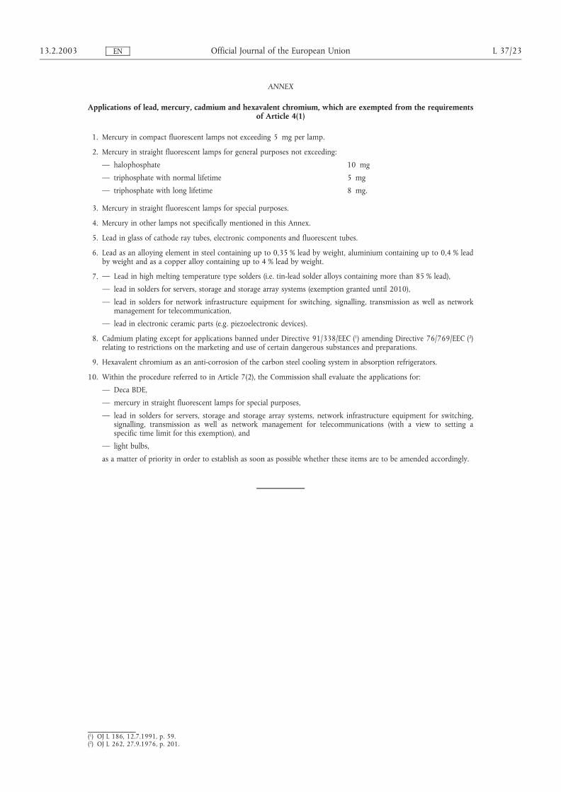
ANNEX
Applications of lead, mercury, cadmium and hexavalent chromium, which are exempted from the requirementsof Article 4(1)
1. Mercury in compact fluorescent lamps not exceeding 5 mg per lamp.
2. Mercury in straight fluorescent lamps for general purposes not exceeding:
— halophosphate 10 mg
— triphosphate with normal lifetime 5 mg
— triphosphate with long lifetime 8 mg.
3. Mercury in straight fluorescent lamps for special purposes.
4. Mercury in other lamps not specifically mentioned in this Annex.
5. Lead in glass of cathode ray tubes, electronic components and fluorescent tubes.
6. Lead as an alloying element in steel containing up to 0,35 % lead by weight, aluminium containing up to 0,4 % leadby weight and as a copper alloy containing up to 4 % lead by weight.
7. — Lead in high melting temperature type solders (i.e. tin-lead solder alloys containing more than 85 % lead),
— lead in solders for servers, storage and storage array systems (exemption granted until 2010),
— lead in solders for network infrastructure equipment for switching, signalling, transmission as well as networkmanagement for telecommunication,
— lead in electronic ceramic parts (e.g. piezoelectronic devices).
8. Cadmium plating except for applications banned under Directive 91/338/EEC (1) amending Directive 76/769/EEC (2)relating to restrictions on the marketing and use of certain dangerous substances and preparations.
9. Hexavalent chromium as an anti-corrosion of the carbon steel cooling system in absorption refrigerators.
10. Within the procedure referred to in Article 7(2), the Commission shall evaluate the applications for:
— Deca BDE,
— mercury in straight fluorescent lamps for special purposes,
— lead in solders for servers, storage and storage array systems, network infrastructure equipment for switching,signalling, transmission as well as network management for telecommunications (with a view to setting aspecific time limit for this exemption), and
— light bulbs,
as a matter of priority in order to establish as soon as possible whether these items are to be amended accordingly.
13.2.2003 L 37/23Official Journal of the European UnionEN
(1) OJ L 186, 12.7.1991, p. 59.(2) OJ L 262, 27.9.1976, p. 201.


Department and Division Department of Management and Engineering
Defence date 2007-03-02 Publishing date (Electronic version)
URL, Electronic version
Title Implementation of Lead-Free Soldering in Highly Reliable Applications
Language X English
Other (specify below)
Report category Licentiate thesis X Degree thesis Thesis C-level Thesis D-level
Other (specify below)
ISBN: ISRN: LIU-IEI-TEK-A--07/0083--SE
Title of series Series number/ISSN
Author Ove Berglund
Abstract The directive of the European parliament and of the council on the Restriction of the use of certain Hazardous Substances (RoHS) in Electrical and Electronic Equipment (EEE) took effect in the European Union on July 1, 2006. The RoHS directive is the reason why this thesis about the implementation of lead-free soldering in highly reliable applications is necessary. The European Lead Free soldering NETwork (ELFNET) status survey from 2005 shows that the majority of the companies are well informed. The transition to lead-free soldering will have a major affect on logistics and administration. The major concern for highly reliable applications are that there are not enough data to understand to what grade lead-free solders will perform differently from lead based solders. Five different types of reliability testing were studied in this thesis; vibration, mechanical shock, thermal shock, thermal cycling and combined environments. Whiskers, voids, brittle fractures and mixed assembly problems were also studied. Individual tests alone should not be used to make definite decisions on lead-free soldering reliability.
Keywords RoHS, Lead-free, Reliability, Solder, Whiskers, Voids, Saab Systems