rasg-pa re prevention seminar · rasg-pa runway excursion prevention seminar ... atsb transport...
TRANSCRIPT

October 09, 2014
RASGRASG--PA Runway Excursion Prevention PA Runway Excursion Prevention SeminarSeminarProper Use of Deceleration DevicesProper Use of Deceleration Devices

This information is the property of Embraer and cannot be used or reproduced without written consent.This information is the property of Embraer and cannot be used or reproduced without written consent.
Brakes & Spoilers
Thrust Reversers
Anti-Skid System & Hydroplaning
Landing Performance Analysis
Statistical Data for Landings
Agenda ItemsAgenda Items
Maximum Performance Landing

This information is the property of Embraer and cannot be used or reproduced without written consent.
Statistical Data for Landings

This information is the property of Embraer and cannot be used or reproduced without written consent.
Source: ATSB Transport Safety Report on Runway Excursion
Excursions During Landing
Analysis on 120 runway excursion fatal accidents during landing from 1998 to 2007

This information is the property of Embraer and cannot be used or reproduced without written consent.
Source: ATSB Transport Safety Report on Runway Excursion
Systems-related Factors (13%)

This information is the property of Embraer and cannot be used or reproduced without written consent.
Source: ATSB Transport Safety Report on Runway Excursion
Crew Technique / Decision-related Factors (37%)

This information is the property of Embraer and cannot be used or reproduced without written consent.
Approach Landing
Contributing Factors (21 events)
Crosswind; 10%
Long Flare; 86%
Contamined Runway; 29%
Unstabilized Approach; 57%
Insufficient Braking; 48%
Others; 19%
Vref Excedance; 71%
Wet Runway; 52%
Embraer Jets Overall Statistics

This information is the property of Embraer and cannot be used or reproduced without written consent.
0
1
2
3
4
5
6
7
Number of combining Contributing Factors per event
Contributing Factors per event (21 events)
Frequency 0 1 5 6 7 2
1 2 3 4 5 6
Embraer Jets Overall Statistics
This information is the property of Embraer and cannot be used or reproduced without written consent.
Brakes & Spoilers
This information is the property of Embraer and cannot be used or reproduced without written consent.
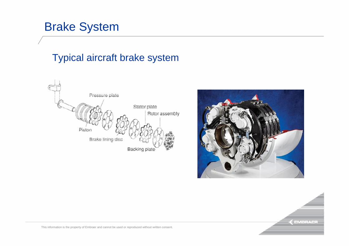
Typical aircraft brake system
Brake System

This information is the property of Embraer and cannot be used or reproduced without written consent.
Background:
Carbon and Steel brakes have different characteristics, so pilots must know the
differences in operation for betters results.
Brakes

This information is the property of Embraer and cannot be used or reproduced without written consent.
Brake wear vs. Number of brake applications
carbon
high
wear
low
wear
few many
steel
high
wear
low
wear
carbon
steel
Brake wear vs. Temperature
cold hot
Carbon Brakes are Different From Steel Brakes

This information is the property of Embraer and cannot be used or reproduced without written consent.
• It is important that you brake for safety
• SOP on brakes usage: • “Apply the brakes with no delay after the main landing gear wheels have
touched down. • Move directly to a single firm and steady brake application and hold pedal
pressure until decelerated to taxi speed.”
• 3 seconds trying to find the centerline can cost you 150 meters (500 feet) of runway distance
REMEMBER:Brake for Safety!
!
Braking Technique

This information is the property of Embraer and cannot be used or reproduced without written consent.
• Aims a deceleration target:• LO: - 4 ft/s2 (– 0.12 g)
• MED: - 8 ft/s2 (– 0.25 g)
• HI: -13 ft/s2 (– 0.40 g)
• System will apply brakes as required to reach target deceleration level
• Deceleration is affected by three factors:• Aerodynamic drag
• Wheel brakes• Reverse thrust
Autobrake Application

This information is the property of Embraer and cannot be used or reproduced without written consent.
time
De
cele
rati
on
De
cele
rati
on
time
Total Deceleration
Brakes Deceleration
Reversers Deceleration
Autobrake Target
Runway Friction able to reach
Autobrake Target
Runway Friction unable to reach
Autobrake Target
Autobrake Application

This information is the property of Embraer and cannot be used or reproduced without written consent.
• Keep in mind:• Autobrake targets DECELERATION RATE, not brake pressure
• Landing Actuation Logic:
• Wheel speed is greater than 60 knots,• WOW reports Ground for 2 seconds ,
• Thrust Lever in Idle
• Note that these 2 seconds are already considered on performance data!
Autobrake Application

This information is the property of Embraer and cannot be used or reproduced without written consent.
Keep in mind:Autobrake to Manual Braking transition behavior
• Autobrake disengages when pedal displacement is greater than 20%• This can command a pressure lower than the one the system was
working at
REMEMBER:Brake for Safety!
!
Autobrake Application
This information is the property of Embraer and cannot be used or reproduced without written consent.
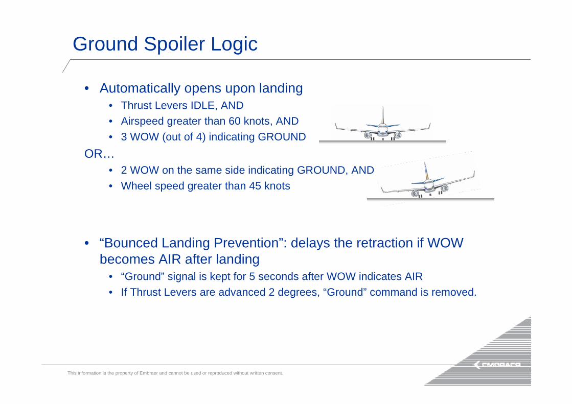
• Automatically opens upon landing• Thrust Levers IDLE, AND• Airspeed greater than 60 knots, AND
• 3 WOW (out of 4) indicating GROUND
OR…• 2 WOW on the same side indicating GROUND, AND
• Wheel speed greater than 45 knots
• “Bounced Landing Prevention”: delays the retraction if WOW becomes AIR after landing
• “Ground” signal is kept for 5 seconds after WOW indicates AIR
• If Thrust Levers are advanced 2 degrees, “Ground” command is removed.
Ground Spoiler Logic

This information is the property of Embraer and cannot be used or reproduced without written consent.
Thrust Reversers

This information is the property of Embraer and cannot be used or reproduced without written consent.
• Thrust Reversers, Ground Spoilers and Wheel Brakes stop the aircraft
• Typical distribution profile:
Airspeed (knots)
Sto
pp
ing
Fo
rce
80 60
Aerod. Drag
Thrust Rev.
Wheel Brake
Braking Devices & Stopping Forces
This information is the property of Embraer and cannot be used or reproduced without written consent.
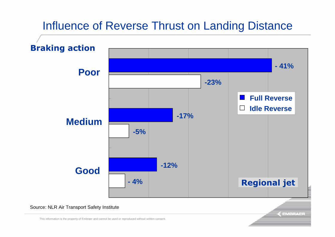
Good
Medium
Poor
Full ReverseIdle Reverse
Braking action
Regional jet - 4%
-5%
-23%
-12%
-17%
- 41%
Source: NLR Air Transport Safety Institute
Influence of Reverse Thrust on Landing Distance

This information is the property of Embraer and cannot be used or reproduced without written consent.
• Promptly use Thrust Reverser, while engine is still at flight idle
• When operating in wet / contaminated runway, apply maximum reverse thrust
• Avoid early Thrust Reverser stowage: only reduce thrust levers to minimum reverse thrust at 60 knots
Thrust Reverser Application

This information is the property of Embraer and cannot be used or reproduced without written consent.
time
Thrust
time
T/R Position
Engine Thrust
Flight Idle vs. Ground Idle engine spin up time
Thrust
Delayed Thrust Reverser Application
Stowed
Deployed
Stowed
Stowed
Deployed
Stowed
Flight Idle
Max Rev Thrust
Ground Idle
Ground Idle
Max Rev Thrust
Ground Idle
t
t+

This information is the property of Embraer and cannot be used or reproduced without written consent.
Thrust Reverser & Crosswind Landings on Slippery Runways

This information is the property of Embraer and cannot be used or reproduced without written consent.
Anti-Skid System& Hydroplaning

This information is the property of Embraer and cannot be used or reproduced without written consent.
System Review:• Anti-skid protection
• On an individual wheel basis, anti-skid will detect a non-spinning wheel and release brake pressure to avoid locking
• Anti-skid operates only above 10 kts wheel speed
• Locked Wheel Crossover Protection• Compares each Inboard/Outboard wheel
pair• If the wheel speed of one wheel of the pair
is 1/3 of the other, system commands zero pressure to the locked one
Anti-Skid System

This information is the property of Embraer and cannot be used or reproduced without written consent.
Anti-Skid System

This information is the property of Embraer and cannot be used or reproduced without written consent.
• Anti-skid systems are designed to achieve optimum braking action
• Several complex comparison of speeds (wheels speed, aircraft speed), hundreds of times per second
• Alleviates brake force application
• Deactivated by the parkingbrake actuation (“emergency”brakes)
Anti-Skid System

This information is the property of Embraer and cannot be used or reproduced without written consent.
• Will not avoid or get the tire out of a hydroplaning condition
• Helps braking in viscous hydroplaning, where there is some wheel speed
• Reducing brake pedal application will not help, let the system work!
Anti-Skid and Hydroplaning

This information is the property of Embraer and cannot be used or reproduced without written consent.
• Hydroplaning is a phenomenon in which a film of standing liquid contaminant causes a tire to lose its contact with the surface, preventing the aircraft from responding to control inputs such as steering and braking.
• Also known as aquaplaning.
• Sometimes people associateit with tire marks after theevent…
Hydroplaning

This information is the property of Embraer and cannot be used or reproduced without written consent.
• The build up of fluid pressure beneath a tire depends on:• Thickness of water film
• Aircraft speed
• Tire pressure/threat quality/footprint• Runway micro and macro texture
• Runway construction
• Three types:
Hydroplaning
Source: FAA Safety at https://www.faasafety.gov
This information is the property of Embraer and cannot be used or reproduced without written consent.
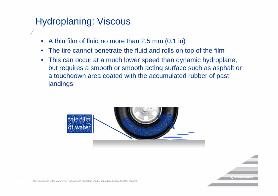
• A thin film of fluid no more than 2.5 mm (0.1 in) • The tire cannot penetrate the fluid and rolls on top of the film• This can occur at a much lower speed than dynamic hydroplane,
but requires a smooth or smooth acting surface such as asphalt or a touchdown area coated with the accumulated rubber of past landings
thin film
of water
Hydroplaning: Viscous

This information is the property of Embraer and cannot be used or reproduced without written consent.
• High-speed phenomenon when there is a film of water on the runway that is at least 2.5 mm (0.1 in) deep
• This results in the formation of a wedge of water beneath the tire
FAA animation at https://www.faasafety.gov/gslac/ALC/course_content.aspx?cID=34&sID=171&preview=true
Hydroplaning: Dynamic
This information is the property of Embraer and cannot be used or reproduced without written consent.
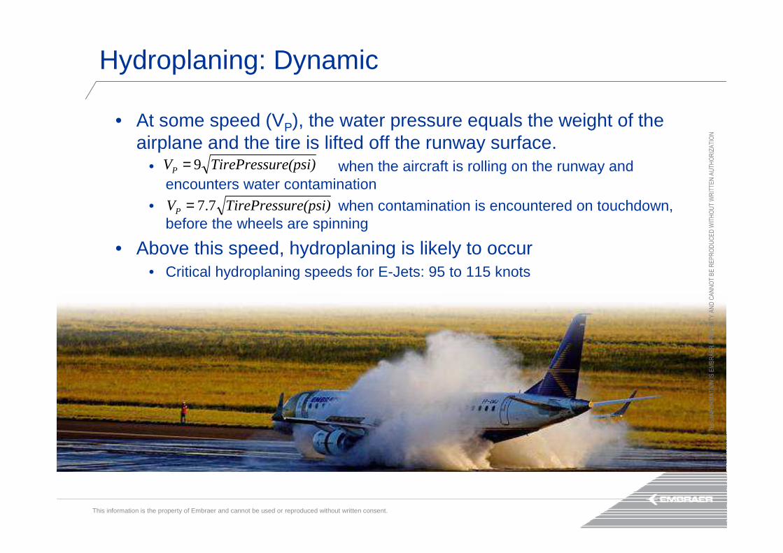
• At some speed (VP), the water pressure equals the weight of the airplane and the tire is lifted off the runway surface.
• when the aircraft is rolling on the runway and encounters water contamination
• when contamination is encountered on touchdown, before the wheels are spinning
• Above this speed, hydroplaning is likely to occur• Critical hydroplaning speeds for E-Jets: 95 to 115 knots
re(psi)TirePressuVP 9=
re(psi)TirePressuVP 7.7=
TH
IS IN
FO
RM
AT
ION
IS E
MB
RA
ER
PR
OP
ER
TY
AN
D C
AN
NO
T B
E R
EP
RO
DU
CE
D W
ITH
OU
T W
RIT
TE
N A
UT
HO
RIZ
AT
ION
Hydroplaning: Dynamic

This information is the property of Embraer and cannot be used or reproduced without written consent.
• Results of a prolonged locked-wheel skid• The tire skidding generates heat that causes the rubber to revert to its original
uncured state
• Reverted rubber acts as a seal between the tire and the runway, and delays water exit from the tire footprint area
• The water heats and is converted to steam which supports the tire off the runway
• Eventually the airplane slows enough to where the tires make contact with the runway surface and the airplane begins to skid
water vapor
TH
IS IN
FO
RM
AT
ION
IS E
MB
RA
ER
PR
OP
ER
TY
AN
D C
AN
NO
T B
E R
EP
RO
DU
CE
D W
ITH
OU
T W
RIT
TE
N A
UT
HO
RIZ
AT
ION
Hydroplaning: Reverted Rubber (Steam or Vapor)

This information is the property of Embraer and cannot be used or reproduced without written consent.
Evidences of Steam Hydroplaning on Tires
Reverted rubber on tires

This information is the property of Embraer and cannot be used or reproduced without written consent.
Evidences of Steam Hydroplaning on the Runway
White marks on runway

This information is the property of Embraer and cannot be used or reproduced without written consent.
• Remember: Thrust Reverser and Ground Spoiler stopping forces are independent of runway condition
• Conduct a positive landing to ensure initial wheel spin-up and initiate firm ground contact upon touchdown
• Consider landing with FLAPS FULL:• Slower approach speed,
• Higher aerodynamic drag
Hydroplaning: How to Deal With?

This information is the property of Embraer and cannot be used or reproduced without written consent.
• Performance numbers are good and necessary, but INFORMATION is to be considered
• How is your pilot fed with information about the destination?• METARs? PIREPs?
In-Flight Landing Distance Assessment

This information is the property of Embraer and cannot be used or reproduced without written consent.
Landing Performance Analysis

This information is the property of Embraer and cannot be used or reproduced without written consent.
Operational requirements: define minimum margins to apply over the certified landing
performance of the airplane
• Dry runway Required Landing Distance (RLD): The airplane shall be able to stop
within 60% of the landing distance available (FAR 121.195(b) and EU-OPS 1.515)
• Wet runway RLD: An additional 15% over the dry RLD shall be required (FAR 121.195(d)
and EU-OPS 1.520)
Margin (40% of RLD)
Dry runway RLD
Threshold
50 ft
Touchdown Full stop
Unfactored landing distance (60% of RLD)
+15%
Wet runway RLD (115% of dry)
The Safety Margins Provided by Requirements

This information is the property of Embraer and cannot be used or reproduced without written consent.
• Baseline performance:
• Model: EMBRAER 190
• Landing configuration: Flaps 5 (Dry/Wet), Flaps FULL (Contaminated)
• Weight: 44,000 kg (97,003 lb)
• Sea level
• No wind
• Threshold crossing at VREF
• Maximum manual braking, applied immediately after main landing gears touch down
• Remarks:
1. Contaminated runway calculation: AMJ 25X1591 (for Slush, depth = 10 mm)
2. Wet runway calculation: it was assumed that µWET is 50% of µDRY. (Obs: this is not a tested value, but an assumption for didactic purposes only)
3. Reverse thrust credit considered for contaminated runways
Case Study

This information is the property of Embraer and cannot be used or reproduced without written consent.
• Runway Condition: Dry
• ULD: 840 m
• Deviation from procedures: 10 kt overspeed at threshold
Margin: 560 m
Threshold
Unfactored landing distance: 840 m
Actual
TouchdownActual
Stop
Margin: 470 mActual landing distance: 930 m
Expected path
Actual path
Expected
Touchdown
Expected
Stop
50 ft
Landing distance margin is reduced by 90 m (16%)
Case Study: VREF Overspeed

This information is the property of Embraer and cannot be used or reproduced without written consent.
Vref + 10 kt
Vref
Vref + 10 kt
Vref
Vref + 10 kt
Vref
Vref + 10 kt
Vref
0 200 400 600 800 1000 1200 1400 1600 1800 2000
Description: Threshold crossing with excess of speed
• Standard speed at threshold: VREF
• Considered speed at threshold: VREF+10 ktWhenever possible, cross
threshold at the standard
speed
Excess of speed reduces
landing distance margins
!
Distance (m)
Flaps 5
Flaps FULL
Dry
Wet
CompactedSnow
Slush
Case Study: VREF Overspeed
This information is the property of Embraer and cannot be used or reproduced without written consent.
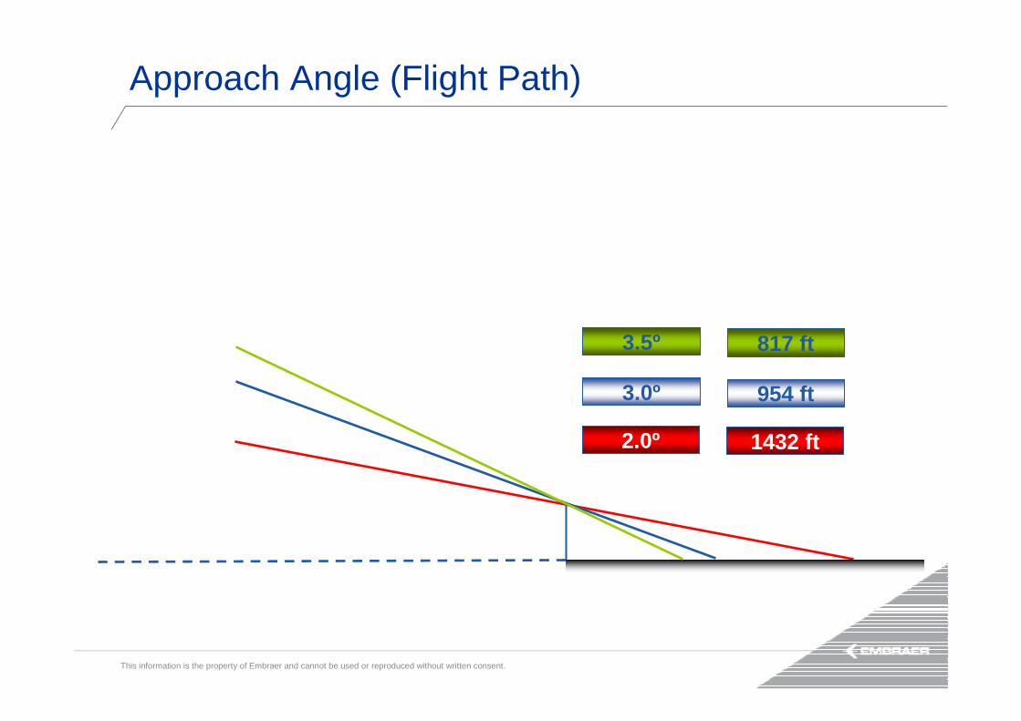
3.0º 954 ft
3.5º 817 ft
2.0º 1432 ft
Approach Angle (Flight Path)

This information is the property of Embraer and cannot be used or reproduced without written consent.
70 ft 1336 ft
90 ft 1717 ft
50 ft 954 ft
High Threshold Crossing

This information is the property of Embraer and cannot be used or reproduced without written consent.
• Runway Condition: Dry
• ULD: 840 m
• Deviation from procedures: 70 ft height at threshold
Margin: 560 m
Threshold
Unfactored landing distance: 840 m
50 ft
Expected
Touchdown
Expected
Stop20 ft
Actual
Touchdown
Actual
Stop
Margin: 450 mActual landing distance: 950 m
Expected path
Actual path
Landing distance margin is reduced by 110 m (20%)
Case Study: High Threshold Crossing

This information is the property of Embraer and cannot be used or reproduced without written consent.
Description: Threshold crossing higher than 50 ft
• Standard height at threshold: 50 ft
• Considered height at threshold: 70 ftWhenever possible, cross
threshold at 50 ft
!
Distance (m)
Dry
Wet
CompactedSnow
Slush70 ft
50 ft
70 ft
50 ft
70 ft
50 ft
70 ft
50 ft
0 200 400 600 800 1000 1200 1400 1600 1800 2000
Case Study: High Threshold Crossing
This information is the property of Embraer and cannot be used or reproduced without written consent.
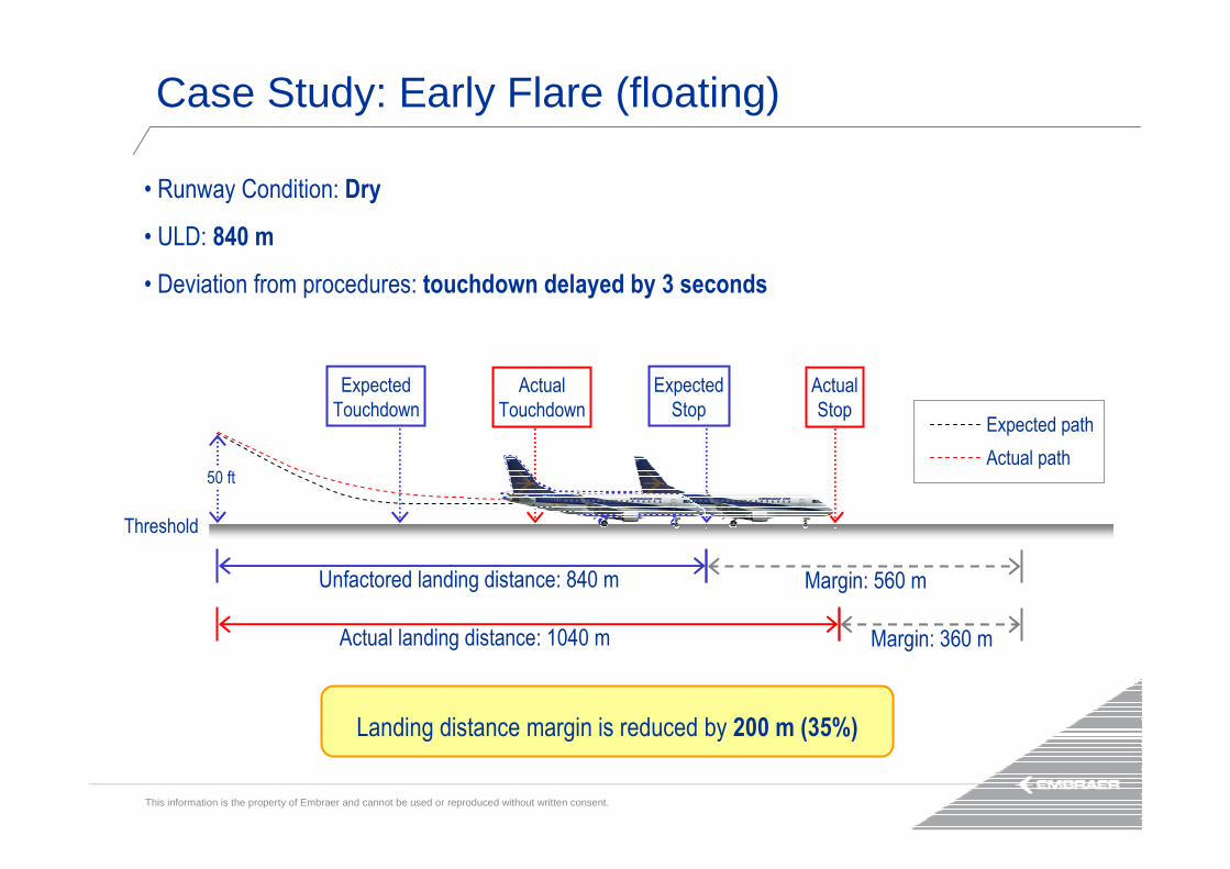
• Runway Condition: Dry
• ULD: 840 m
• Deviation from procedures: touchdown delayed by 3 seconds
Margin: 560 m
Threshold
Unfactored landing distance: 840 m
50 ft
Expected
Touchdown
Expected
Stop
Actual
Touchdown
Actual
Stop
Margin: 360 mActual landing distance: 1040 m
Expected path
Actual path
Landing distance margin is reduced by 200 m (35%)
Case Study: Early Flare (floating)

This information is the property of Embraer and cannot be used or reproduced without written consent.
Early flare
Normal flare
Early flare
Normal flare
Early flare
Normal flare
Early flare
Normal flare
0 200 400 600 800 1000 1200 1400 1600 1800 2000
• Description: Early flare resulting in extended air distance
• Standard procedure: no flare delay
• Considered procedure: early flare, delaying touchdown by 3 seconds
Avoid floating above the
runway, conduct a firm
landing
!
Distance (m)
Dry
Wet
CompactedSnow
Slush
Case Study: Early Flare (floating)

This information is the property of Embraer and cannot be used or reproduced without written consent.
Unstabilized
Stabilized
Unstabilized
Stabilized
Unstabilized
Stabilized
Unstabilized
Stabilized
0 200 400 600 800 1000 1200 1400 1600 1800 2000
Description: Simulated unstabilized approach. Procedure deviations consideredsimultaneously :
• Threshold crossing with V REF + 10 kt at 70 ft height
• Touchdown delayed for 3 seconds
The combined effects are
worse than those of the
isolated factors
In wet and contaminated
runways, operational
margins are exceeded!
!
Distance (m)
Dry
Wet
CompactedSnow
Slush
Case Study: Unstabilized Approach

This information is the property of Embraer and cannot be used or reproduced without written consent.
Actual
Touch downActual
Stop
• Runway Condition: Dry
• ULD: 840 m
• Deviation from procedures: partial brakes application
Margin: 560 m
Threshold
Unfactored landing distance: 840 m
50 ft
Exp. / Actual
Touchdown
Expected
Stop
Margin 170 mActual landing distance: 1230 m
Expected path
Actual path
Landing distance margin is reduced by 390 m (70%)
Case Study: Partial Brakes Application

This information is the property of Embraer and cannot be used or reproduced without written consent.
Partial braking
Maximum Braking
Partial braking
Maximum Braking
Partial braking
Maximum Braking
Partial braking
Maximum Braking
0 200 400 600 800 1000 1200 1400 1600 1800 2000
Description: Dispatch calculation always considers that maximum brakes will be applied
• Certified braking procedure: Maximum braking capacity applied
• Considered procedure: Partial brakes application
APPLY FULL BRAKES!
Low braking has significant
impact on margins
Maximum braking grants
maximum possible efficiency,
let the anti-skid work!
!
Distance (m)
Dry
Wet
CompactedSnow
Slush
Case Study: Partial Brakes Application

This information is the property of Embraer and cannot be used or reproduced without written consent.
LO
MED
HI
Max Braking
LO
MED
HI
Max Braking
LO
MED
HI
Max Braking
LO
MED
HI
Max Braking
0 250 500 750 1000 1250 1500 1750 2000
Description: Autobrake use not adequate. The dispatch was calculated considering manual brake application. Landing is performed with autobrake on
• Autobrake status considered for dispatch: Maximum manual braking
• Autobrake selected during approach: HI, MED or LO
Distance (m)
Dry
Wet
CompactedSnow
Slush
For landing, autobrake will
always give lower performance
compared to manual braking.
Autobrake HI is not full braking
and the transition is longer
than in manual
Improper use can result in
highly negative margins!
!
Case Study: Improper Autobrakes Application

This information is the property of Embraer and cannot be used or reproduced without written consent.
TR not applied
TR applied
TR not applied
TR applied
TR not applied
TR applied
0 500 1000 1500 2000 2500 3000
Description: Dispatch is calculated considering that Thrust Reverser (TR) will be applied . Landing is performed without it
• Reverse thrust considered for dispatch: All reversers applied
• Reverse thrust applied at landing: reversers not deployed
If reverse thrust was
considered for dispatch
(contaminated runways
only), apply reversers as
soon as possible
Improper use can result in
no margins when operating
in very slippery runways!
!
Distance (m)
CompactedSnow
Slush
Ice
Case Study: Improper Reverse Thrust Use
This information is the property of Embraer and cannot be used or reproduced without written consent.
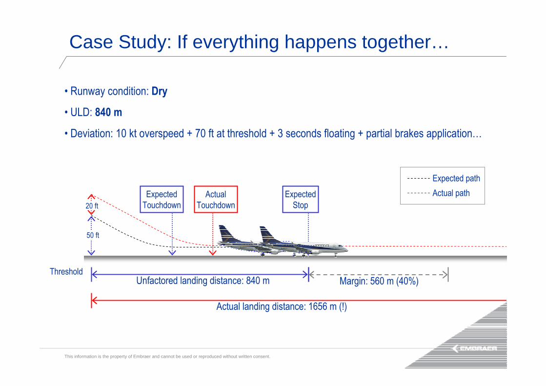
• Runway condition: Dry
• ULD: 840 m
• Deviation: 10 kt overspeed + 70 ft at threshold + 3 seconds floating + partial brakes application…
Margin: 560 m (40%)Threshold
Unfactored landing distance: 840 m
50 ft
Expected
Touchdown
Expected
Stop20 ft
Actual
Touchdown
Actual landing distance: 1656 m (!)
Expected path
Actual path
Case Study: If everything happens together…
This information is the property of Embraer and cannot be used or reproduced without written consent.
Maximum Performance Landing
This information is the property of Embraer and cannot be used or reproduced without written consent.
Maximum Performance LandingA set of techniques that leads to stopping the airplane with the least landing run. The following recommendations apply:
• Review the approach procedures and speeds earlier: keep your situation awareness over the stabilized approach and stabilized landing is mandatory for a well-planned and executed approach.
• Use Full Flaps.
• Cross the Threshold at Screen Height of 50 ft and VREF.
• Avoid extended flare.
• Conduct a positive landing.
• Apply maximum Thrust Reverser.
• Immediately after the main landing gear wheels have touched down apply firm and steady maximum manual brakes and hold pedal pressure until the airplane decelerates to a safe taxi speed within the runway.
• Lower nose wheel immediately to the runway. It will decrease lift and increase main landing gear loading.

This information is the property of Embraer and cannot be used or reproduced without written consent.
Conclusions

This information is the property of Embraer and cannot be used or reproduced without written consent.
• Maintain situation awareness after touch down
• Use Thrust Reversers promptly on touch down and until stop is assured
• Autobrake targets deceleration rate, not brake pressure
• Anti-skid functionality is overridden after application of Emergency Brakes
• Dry runways: braking time and intensity play a major role
• Contaminated runways: braking is less effective. Use of reverse thrust must be performed accordingly
• Use Maximum Performance Landing whenever necessary
• Brake for safety!
To grant a safe landing:– Follow the standard procedures . Leave margins for the unknown!
Conclusions

This information is the property of Embraer and cannot be used or reproduced without written consent.
QUESTIONS

This information is the property of Embraer and cannot be used or reproduced without written consent.
Gracias!