ray tracing
TRANSCRIPT


February 5, 2015 2
When creating any sort of computer graphics, you must have a list of objects that you want your software
to render. These objects are part of a scene or world (Fig. 2), so when we talk about ``looking at the
world,'' we're not posing a philosophical challenge, but just referring to the ray tracer drawing the objects
from a given viewpoint. In graphics, this viewpoint is called the eye or camera. Following this camera
analogy, just like a camera needs film onto which the scene is projected and recorded, in graphics we
have a view window on which we draw the scene. The difference is that while in cameras the film is
placed behind the aperture or focal point, in graphics the view window is in front of the focal point. So the
color of each point on real film is caused by a light ray (actually, a group of rays) that passes through the
aperture and hits the film, while in computer graphics each pixel of the final image is caused by a
simulated light ray that hits the view window on its path towards the eye. The results, however, are the
same.
Some Terminology

February 5, 2015 3
Rendering is a process that takes as its input a set of objects and produces as
its output an array of pixels.
One way or another, rendering involves considering how each object contributes
to each pixel; it can be organized in two general ways.
1. Object-order rendering, each object is considered in turn, and for each
object all the pixels that it influences are found and updated.
2. Image order rendering, each pixel is considered in turn, and for each pixel all
the objects that influence it are found and the pixel value is computed.
Introduction

February 5, 2015 4
Ray tracing is an image-order algorithm for making renderings of 3D
scenes, and we’ll consider it’s first, because it’s possible to get a ray tracer
working without developing any of the mathematical machinery that’s used
for object-order rendering.
… Introduction

February 5, 2015 5
Ray tracing is one of the numerous techniques that exist to render
images with computers. The idea behind ray tracing is that physically
correct images are composed by light and that light will usually come
from a light source and bounce around as light rays (following a broken
line path) in a scene before hitting our eyes or a camera.
What is ray tracing ?
Ray tracing is a method to produce realistic images; it determines
visible surfaces in an image at the pixel level

February 5, 2015 6
Ray Tracing - Applications
o Visual effects in movies and commercials
• Major software packages have built-in ray tracers:
e. g. Maya, 3ds Max (Autodesk), Houdini (Side Effects Software)
o Visualization of architectural design
• Consideration of realistic indoor and outdoor illumination
o Automotive design
o Flight and car simulators
o Computer games

February 5, 2015 7
• Light interaction among surfaces: the lights issued by the light sources, reflect
and refract when they reach the surface of the objects.
• Fundamentals of ray tracing
• Direct lights: lights issued by the light sources.
• Indirect lights: lights reflected and refracted by surfaces.
• Direct reflection and direct refraction: the reflection and refraction of the
direct lights.
• Indirect reflection and indirect refraction: the reflection and refraction of the
indirect lights.

February 5, 2015 8
A ray tracer works by computing one pixel at a time, and for each pixel the basic
task is to find the object that is seen at that pixel’s position in the image. Each
pixel “looks” in a different direction, and any object that is seen by a pixel must
intersect the viewing ray, a line that emanates from the viewpoint in the direction
that pixel is looking.
A basic ray tracer therefore has three parts:
1. ray generation, which computes the origin and direction of each pixel’s
viewing ray based on the camera geometry;
2. ray intersection, which finds the closest object intersecting the viewing ray;
3. shading, which computes the pixel color based on the results of ray
intersection.
Ray Tracer

February 5, 2015 9
The structure of the basic ray tracing program is:
for each pixel do
compute viewing ray
find first object hit by ray and its surface normal n
set pixel color to value computed from hit point, light, and n
Ray Tracer

February 5, 2015 10
• Basic algorithm traces the mirror reflection and refraction of light rays..
• The light sources issue lights. The lights hit the surfaces and are reflected
or refracted. The propagation directions of lights are changed. Lights
continue the propagation along the new directions, until they hit new objects.
• A small portion of the lights issued by the light sources will enter the eyes.
• In reality, the propagation direction of lights are opposite to the direction of
ray tracing.
Ray tracing Algorithm


February 5, 2015 17
Light sources send off photons in all directions
Model these as particles that bounce off objects in the scene
Each photon has a wavelength and energy (color and intensity)
When photons bounce, some energy is absorbed, some reflected, some
transmitted
If we can model photon bounces we can generate images Technique: follow
each photon from the light source until:
• All of its energy is absorbed (after too many bounces).
• It departs the known universe (not just the part of the world that is within the
viewing volume!).
• It strikes the image and its contribution is added to appropriate pixel.
Light is Bouncing Photons

February 5, 2015 18
• light is modeled as geometric rays
travels in straight lines (e. g., diffraction / bending is not considered)
travels at infinite speed (ray tracing computes steady state of light)
is emitted by light sources
is absorbed or scattered / reflected at surfaces
• radiance
characterizes strength and direction of radiation / light
is measured by sensors
is computed in computer-generated images
is preserved along lines in space
does not change with distance
Ray Tracing - Motivation

February 5, 2015 19
Ray Tracing vs. Rasterization
rasterization
• given a set of viewing rays and a primitive, efficiently compute the
subset of rays hitting the primitive
• loop over all primitives
• no explicit representation of rays
ray tracing
• given a viewing ray and a set of primitives, efficiently compute the
subset of primitives hit by the ray
• loop over all viewing rays
• explicit representation of rays

February 5, 2015 20
• A ray is issued from the view point V through a pixel (x, y).
• The ray hits the first object along its propagation.
• The reflection and refraction take place at the intersection point.
• Continue to trace the reflected ray and refracted ray.
Ray Tracer

February 5, 2015 21
Rays are the paths of these photons
This method of rendering by following photon paths is called ray tracing
Forward ray tracing follows the photon in direction that light travels (from the
source).
BIG problem with this approach:
Only a tiny fraction of rays reach the image.
Many, many rays are required to get a value
for each pixel.
Ideal Scenario:
We'd like to magically know which rays
will eventually contribute to the image,
and trace only those.
Forward Ray Tracing


February 5, 2015 25
The solution is to start from the image and trace backwards—backward
ray tracing
Start from the image and follow the ray until the ray finds (or fails to find) a
light source
Backward Ray Tracing


February 5, 2015 27
Basic idea:
Each pixel gets light from just one direction—the line through the image point and
focal point
Any photon contributing to that pixel’s color has to come from this direction
So head in that direction and see what is sending light
If we hit a light source—done
If we find nothing—done
If we hit a surface—see where that surface is lit from
At the end we’ve done forward ray tracing, but ONLY for the rays that contribute to
the image
Backward Ray Tracing

February 5, 2015 28
Recursive Ray Tracing
Four ray types:
Eye rays: originate at the eye
Shadow rays: from surface point toward light source
Reflection rays: from surface point in mirror direction
Transmission rays: from surface point in refracted direction

February 5, 2015 29
Ray Tracing – Basic Idea
A ray is a geometric entity with an origin and a direction
A ray of light is traced in a backwards direction. That is, we start from the eye
and trace the ray through a pixel in the image plane into the scene and
determine what it hits.
Classic ray tracing shoots virtual view rays into the scene from the camera
and traces their paths as they bounce around

February 5, 2015 30
Ray Tracing Algorithm
for each pixel
{
determine viewing direction
intersect ray with scene
compute illumination
store result in pixel
}

February 5, 2015 31
The basic algorithm is
compute u, v, w basis vectors
for each pixel do
shoot ray from eye point through pixel (x, y) into scene
intersect with all surfaces, find first one the ray hits shade that point to
compute pixel (x, y)’s color
Ray Tracing


February 5, 2015 33
The basic tools of ray generation are the viewpoint (or view direction, for
parallel views) and the image plane. There are many ways to work out the
details of camera geometry; in this section we explain one based on
orthonormal bases that supports normal and oblique parallel and orthographic
views.
In order to generate rays, we first need a mathematical representation for a
ray.
A ray is really just an origin point and a propagation direction; a 3D parametric
line is ideal for this. The 3D parametric line from the eye e to a point s on the
image plane as in figure, is given by
p(t) = e + t(s − e).

February 5, 2015 34
This should be interpreted as, “we advance from e along the vector (s − e) a
fractional distance t to find the point p.” So given t, we can determine a
point p.
The point e is the ray’s origin, and s − e is the ray’s direction..
Note that p(0) = e, and p(1) = s, and more generally, if 0 < t1 < t2, then
p(t1) is closer to the eye than p(t2). Also, if t < 0, then p(t) is “behind” the
eye.
These facts will be useful when we search for the closest object hit by the ray
that is not behind the eye.


February 5, 2015 36
Shadow Rays
l the same for both points because this is a directional
light (infinitely far away)
p+tl dose not hit any objects
q+tl dose hit an object and is shadowed

February 5, 2015 37
We start by ‘shooting’ rays from the camera out into the scene, We can render
the pixels in any order we choose (even in random order!), but we will keep it
simple and go from top to bottom, and left to right
We loop over all of the pixels and generate an initial primary ray (also called a
camera ray or eye ray), The ray origin is simply the camera’s position in world
space.
Camera Rays

February 5, 2015 38
Since v and w have to be perpendicular, the up vector and v are not generally
the same. But setting the up vector to point straight upward in the scene will
orient the camera in the way we would think of as “upright.”

February 5, 2015 39 [email protected]
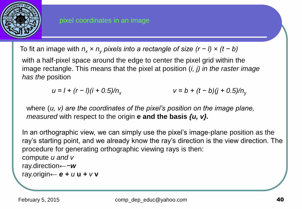
February 5, 2015 40
with a half-pixel space around the edge to center the pixel grid within the
image rectangle. This means that the pixel at position (i, j) in the raster image
has the position
u = l + (r − l)(i + 0.5)/nx v = b + (t − b)(j + 0.5)/ny
pixel coordinates in an image
To fit an image with nx × ny pixels into a rectangle of size (r − l) × (t − b)
where (u, v) are the coordinates of the pixel’s position on the image plane,
measured with respect to the origin e and the basis {u, v}.
In an orthographic view, we can simply use the pixel’s image-plane position as the
ray’s starting point, and we already know the ray’s direction is the view direction. The
procedure for generating orthographic viewing rays is then:
compute u and v
ray.direction←−w
ray.origin← e + u u + v v

February 5, 2015 41
Ray Tracing was developed as one approach to modeling the properties
of global illumination.
• The basic idea is as follows:
For each pixel:
– Cast a ray from the eye of the camera through the pixel, and find
the first surface hit by the ray.
– Determine the surface radiance at the surface intersection with a
combination of local and global models.
– To estimate the global component, cast rays from the surface point
to possible incident directions to determine how much light comes from
each direction. This leads to a recursive form for tracing paths of light
backwards from the surface to the light sources.

February 5, 2015 42
• Tracing rays of light through a scene to compute the radiance that is
perceived by a sensor
• Tracing a path from a camera through a pixel position of a virtual image
plane to compute the color of an object that is visible along the path

February 5, 2015 43
Sometimes the ray misses all of the objects Sometimes the ray will hit an object

February 5, 2015 44
If the ray hits an object, we want to know if that point on the object is in a
shadow. So, when the ray hits an object, a secondary ray, called a "shadow"
ray, is shot towards the light sources.

February 5, 2015 45
If this shadow ray hits another object before it hits a light source, then the first
intersection point is in the shadow of the second object. For a simple illumination
model this means that we only apply the ambient term for that light source.

February 5, 2015 46
Also, when a ray hits an object, a reflected
ray is generated which is tested against all of
the objects in the scene
If the reflected ray hits an object then a local
illumination model is applied at the point of
intersection and the result is carried back to the
first intersection point.
Reflected Ray

February 5, 2015 47
If the intersected object is transparent,
then a transmitted ray is generated and
tested against all the objects in the scene.
Transmitted Ray
As with the reflected ray, if the transmitted
ray hits an object then a local illumination
model is applied at the point of intersection
and the result is carried back to the first
intersection point.

February 5, 2015 48
The reflected rays can generate other reflected rays that can generate other
reflected rays, etc. The next sequence of three images shows a simple scene with
no reflection, a single reflection, and then a double reflection.
Scene with no reflection rays Scene with one layer of reflection Scene with two layers of reflection

February 5, 2015 49
1- Fire a single ray from each pixel position into the scene along the projection
path.
•Determine which surfaces the ray intersects and order these by distance from
the pixel.
3- The nearest surface to the pixel is the visible surface for that pixel.
4- For transparent surfaces send a ray through the surface in the refraction
direction.
5- Repeat the process for these secondary rays.
We terminate a ray-tracing path when any one of the following conditions
is satisfied:
–The ray intersects no surfaces.
–The ray intersects a light source that is not a reflecting surface.
–A maximum allowable number of reflections have taken place.
Ray tracing proceeds as follows:

February 5, 2015 50
The initial camera ray is then tested for intersection with the 3D scene, which
contains a bunch of triangles and/or other primitives, If the ray doesn’t hit
anything, then we can color the pixel to some specified ‘background’ color,
Otherwise, we want to know the first thing that the ray hits (it is possible
that the ray will hit several surfaces, but we only care about the closest one to
the camera)
For the intersection, we need to know the position, normal, color, texture
coordinate, material, and any other relevant information we can get about
that exact location
If we hit somewhere in the center of a triangle, for example, then this
information would get computed by interpolating the vertex data

February 5, 2015 51
• For each ray we need to test which objects are intersecting the ray:
– If the object has an intersection with the ray we calculate the distance
between viewpoint and intersection
– If the ray has more than one intersection, the smallest distance identifies
the visible surface.
• Primary rays are rays from the view point to the nearest intersection point
Ray tracing: Primary rays

February 5, 2015 52
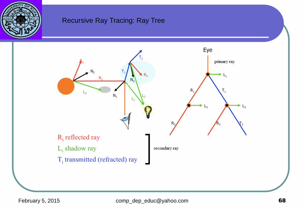
• Secondary rays are rays originating at the intersection points
• Secondary rays are caused by
– rays reflected off the intersection point in the direction of reflection
– rays transmitted through transparent materials in the direction of refraction
– shadow rays
Ray tracing: Secondary rays
The primary rays are the initial rays shot from the camera. Any reflected
rays (and others, like refracted rays, etc.), are called secondary rays.

February 5, 2015 53
A- Lighting
Once we have the key intersection information (position, normal, color,
texture coordinates, etc.) we can apply any lighting model we want, This
can include procedural shades, lighting computations, texture lookups,
texture combining, bump mapping, The result of the lighting equation is a
color, which is used to color the pixel
Types of secondary rays

February 5, 2015 54
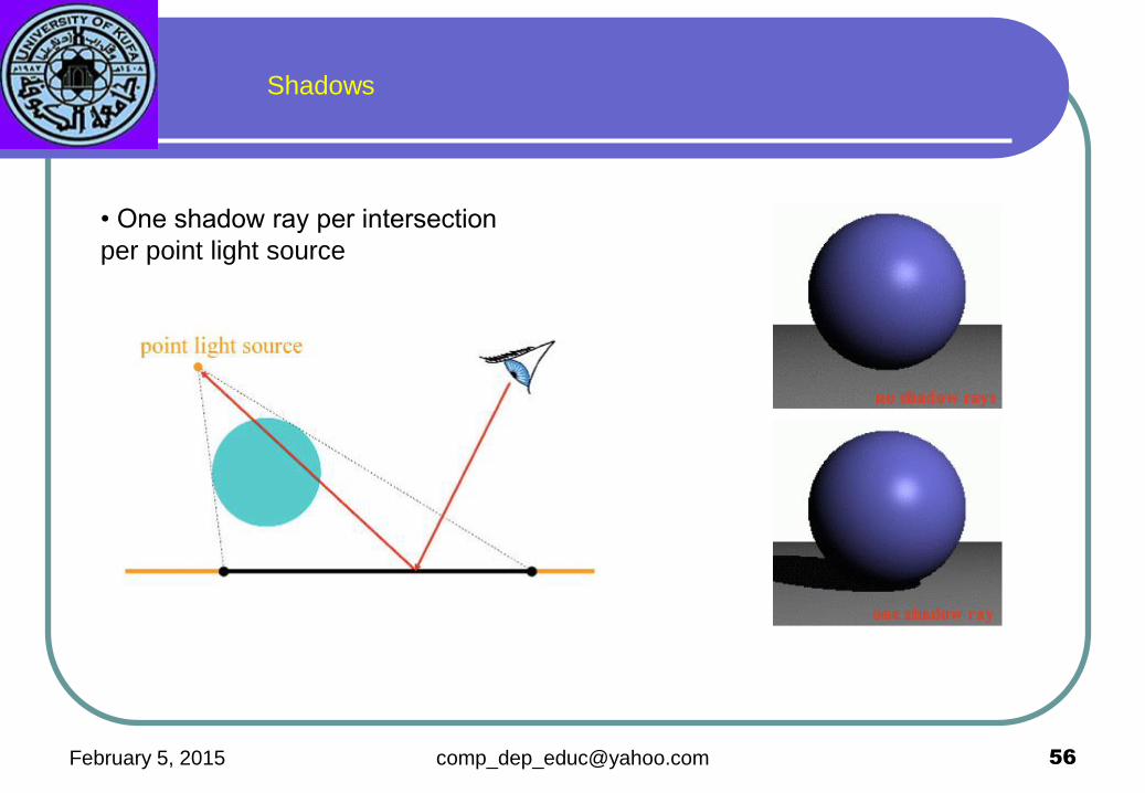
B- Shadow Rays
Shadows are an important lighting effect that can easily be computed with ray
tracing, If we wish to compute the illumination with shadows for a point, we
shoot an additional ray from the point to every light source
A light is only allowed to contribute to the final color if the ray doesn’t hit
anything in between the point and the light source, Shadow rays behave
slightly differently from primary (and secondary) rays
Normal rays (primary & secondary) need to know the first surface hit and then
compute the color reflected off of the surface, Shadow rays, however, simply
need to know if something is hit or not
Types of secondary rays

February 5, 2015 55
How do we add shadows?
L = ka + s(kd (n⋅ l) + ks(v⋅ r)q )Is + kreflectedLreflected + krefractedLrefracted
February 5, 2015 56
• One shadow ray per intersection
per point light source
Shadows

February 5, 2015 57
• Multiple shadow rays to sample
area light source
Soft shadows

February 5, 2015 58
C- Reflection Rays
Another powerful feature often associated with ray tracing is accurate
reflections, If we wanted to render a surface as a perfect mirror, instead of
computing the lighting through the normal equation, we just create a new
reflection ray and trace it into the scene.
Types of secondary rays

February 5, 2015 59
If the reflection ray hits a normal material, we just compute the illumination and
use that for the final color.
If the reflection ray hits another mirror, we just recursively generate a new
reflection ray and trace that.
In this way, we can render complex mirrored surfaces that include reflections,
reflections of reflections, reflections of reflections of reflections…,To prevent the
system from getting caught in an infinite loop, it is common to put an upper limit
on the ‘depth’ of the recursion. 10 or lower works for most scenes, except
possibly for ones with lots of mirrored surfaces
Reflection

February 5, 2015 60
Surfaces in the real world don’t act as perfect mirrors, Real mirrors will absorb a
small amount of light and only reflect maybe 95%-98% of the light
Some reflecting surfaces are tinted and will reflect different wavelengths with
different strengths, This can be handled by multiplying the reflected color by the
mirror color at each bounce, We can also simulate partially reflective materials
like polished plastic, which have a diffuse component as well as a shiny specular
component
For a material like this, we would apply the normal lighting equation, including
shooting shadow rays, to compute the diffuse component, then add a
contribution from a reflection ray to get the final color (the diffuse and specular
components should be weighted so as not to violate conservation of energy…)
Reflection

February 5, 2015 61
D-Transmission Rays
Ray tracing can also be used to accurately render the light bending in
transparent surfaces due to refraction, this is called transmission instead
of refraction.
Types of secondary rays

February 5, 2015 62
When a ray hits a transparent surface (like glass, or water…), we generate a new
refracted ray and trace that, in a similar way as we did for reflection
We will assume that the transmitted ray will obey Snell’s law
(n1 sinθ1 = n2 sinθ2), where n1 and n2 are the index of refraction for the two
materials, Computing Transmission (Refraction) Direction
Transmission Rays

February 5, 2015 63
When light traveling in a material with a high index of refraction hits a material
with a low index of refraction at a steep angle, we get a total internal reflection,
When this happens, no refraction ray is generated, This effect can be visible when
one is scuba diving and looks up at the water surface. One can only see rays
refracting to the outside world in a circular area on the water surface above.
Total Internal Reflection
A consequence of Snell’s law is a phenomenon known as total internal reflection.
If the ratio of refractive indices n2/n1 is less than unity, there will be some ‘critical’
angle of incidence above which the angle of refraction is always greater than 90
degrees.

February 5, 2015 64
Note that there is no critical angle when n2 > n1 since sinθ cannot be greater than 1.
This means, for example, that total internal reflection can occur when light travelling
through water or glass strikes air, but not the other way around.
Mathematically, we can find the critical angle θc by setting θ2 equal to 90 degrees in
Snell’s law and rearranging. When θ2=90°, sinθ2 = 1, and we have
θc = sin-1(n2/n1)

February 5, 2015 65
When light hits a transparent surface, we will actually generate two new rays
and trace both of them into the scene and combine the results, The results of an
individual traced ray is a color, This color is used as the pixel color for primary
rays, but for secondary rays, the color is combined somehow into the final
pixel color
In a refraction situation, for example, we spawn off two new rays and combine
them according to the Fresnel equations, The Fresnel equations describe how
the transmitted (refracted ) ray will dominate when the incoming ray is normal to
the surface, but the reflection will dominate when the incoming ray is edge-on
Spawning Multiple Rays

February 5, 2015 66
Fresnel Equations
describe the behavior of light when moving between media of differing refractive indices.
a wave travelling from a low to high
refractive index medium
When light moves from a medium of a given refractive index n1 into a second medium with
refractive index n2, both reflection and refraction of the light may occur. The Fresnel equations
describe what fraction of the light is reflected and what fraction is refracted (i.e., transmitted).

February 5, 2015 67
The classic ray tracing algorithm includes features like shadows, reflection,
refraction, and custom materials,
A single primary ray may end up spawning many secondary and shadow
rays, depending on the number of lights and the arrangement and type of
materials ,These rays can be thought of as forming a tree like structure
Recursive Ray Tracing

February 5, 2015 69
Tracing a single ray requires determining if that ray intersects any one of
potentially millions of primitives, This is the basic problem of ray intersection.
Many algorithms exist to make this not only feasible, but remarkably efficient
Tracing one ray is a complex problem and requires serious work to make it run
at an acceptable speed, of course, the big problem is the fact that one needs to
trace lots of rays to generate a high quality image.
Ray Intersections
The general idea behind ray-object intersections is to put the mathematical
equation for the ray into the equation for the object and determine if there is a real
solution. If there is a real solution then there is an intersection (hit) and we must
return the closest point of intersection and the normal (N) at the intersection point.

February 5, 2015 70
1-Ray-Scene Intersection
One of the key components of a ray tracer is the system that determines what
surface the ray hits, A typical 3D scene may have well over 1,000,000 primitives.
As usual, triangles tend to be the primitive of choice, but one advantage of a ray
tracer is that one can intersect rays with more complex surfaces such as
spheres, displacement mapped surfaces, fractals, and more .
Ray Intersection
If Rd is normalized, then t equals the distance of the ray from origin in World Coordinates,
else it is just a multiple of Rd, so we want to normalize Rd. Note that many of the
intersection computations require the solution of the quadratic equation.
We define a ray as:
R0 = [x0, y0, z0] - origin of ray
Rd = [xd, yd, zd] - direction of ray then define a set of
points on the ray: R(t) = R0 + Rd * t with t > 0.0

February 5, 2015 71
2-Ray-Object Intersection
We will say that our scene is made up of several individual ‘objects’, For our
purposes, we will allow the concept of an object to include primitives such as
triangles and spheres, or even collections of primitives or other objects
In order to be render-able, an object must provide some sort of ray intersection
routine. The idea is that we can derive specific objects, like triangles, spheres,
etc., and then write custom ray intersection routines for them , The ray
intersect routine takes a ray as input, and returns true if the object is hit
and false if it is missed, If the object is hit, the intersection data is filled in
Ray Intersection

February 5, 2015 72
3-Ray-Sphere Intersection
Let’s see how to test if a ray intersects a sphere, The ray has an origin at
point p and a unit length direction u, and the sphere has a center c and a
radius r
The ray itself is the set of points p+α u, where α ≥ 0
We start by finding the point q which is the point on the ray-line closest to the
center of the sphere. The line qc must be perpendicular to vector u, in other
words, (q-c)·u=0, or (p+αu-c)·u=0, We can solve the value of α that satisfies
that relationship: α=-(p-c)·u, so q=p-((p-c)·u)u
Ray Intersection

February 5, 2015 73
Ray Intersection
To solve algebraically, substitute the ray equation into sphere equation and solve for t.
For ray:
x = X0 + Xd * t
y = Y0 + Yd * t
z = Z0 + Zd * t
putting X, Y, Z into the sphere equation for x, y, z
(X0 + Xd * t - xc)2 + (Y0 + Yd * t - yc)
2 + (Z0 + Zd * t - zc)2 = R2
or A*t2 + B*t + C = 0
with: A = Xd2 + Yd
2 + Zd2
B = 2 * (Xd * (X0 - Xc) + Yd * (Y0 - Yc) + Zd * (Z0 - Zc))
C = (X0 - Xc)2 + (Y0 - Yc)
2 + (Z0 – Zc)2 – R2

February 5, 2015 74
4-Ray-Plane Intersection
A plane is defined by a normal vector n and a distance d, which is the distance
of the plane to the origin, We test our ray with the plane by finding the point
q which is where the ray line intersects the plane
For q to lie on the plane it must satisfy d=q·n=p·n+αu·n
We solve for α: α=(d-p·n)/(u·n), However, we must first check that the
denominator is not 0, which would indicate that the ray is parallel to the plane
If α≥0 then the ray intersects the plane, otherwise, the plane lies behind the ray,
in the wrong direction
Ray Intersection

February 5, 2015 75
5-Ray-Triangle Intersection
To intersect a ray with a triangle, we must first check if the ray intersects the
plane of the triangle, If we are treating our triangle as one-sided, then we can
also verify that the origin of the ray is on the outside of the triangle
Once we know that the ray hits the plane at point q, we must verify that q
lies inside the 3 edges of the triangle.
Ray Intersection

February 5, 2015 76
Complex scenes can contain millions of primitives, and ray tracers need to
trace millions of rays. This means zillions of potential ray-object intersections.
If every ray simply looped through every object and tested if it intersected, we
would spend forever just doing loops, not even counting all of the time doing
the intersection testing.
Therefore, it is absolutely essential to employ some sort of acceleration
structure to speed up the ray intersection testing, An acceleration structure is
some sort of data structure that groups objects together into some
arrangement that enables the ray intersection to be sped up by limiting which
objects are tested.
There are a variety of different acceleration structures in use, but most of the
successful ones tend to be based on some variation of hierarchical
subdivision of the space around the group of objects.
Acceleration Structures

February 5, 2015 77 [email protected]
1-Bounding Volume Hierarchies
The basic concept of a bounding volume hierarchy is a complex object in a
hierarchy of simpler ones, For example, if one were using spheres as their
bounding volume, we could enclose the entire scene in one big sphere, Within
that sphere are several other spheres, each containing more spheres, until we
finally get to the bottom level where spheres contain actual geometry like
triangles
To test a ray against the scene, we traverse the hierarchy from the top level,
When a sphere is hit, we test the spheres it contains, and ultimately the
triangles/primitives within
In general, a bounding volume hierarchy can reduce the ray intersection time
from O(n) to O(log n), where n is the number of primitives in the scene
The sphere hierarchy makes for a good example of the concept, but in practice,
sphere hierarchies are not often used for ray tracing
Acceleration Structures

February 5, 2015 [email protected] 78
One reason is that it is not clear how to automatically group an arbitrary set
of triangles into some number of spheres, so various heuristic options exist.
Also, as the spheres are likely to overlap a lot, they end up triggering a lot of
redundant intersection tests.
Acceleration Structures

February 5, 2015 79
2-Octrees
The octree starts by placing a cube around the entire scene, If the cube contains
more than some specified number of primitives (say, 10), then it is split equally into
8 cubes, which are then recursively tested and possibly re-split
The octree is a more regular structure than the sphere tree and provides a clear
rule for subdivision and no overlap between cells, This makes it a better choice
usually, but still not ideal
Acceleration Structures

February 5, 2015 80
3-KD Trees
The KD tree starts by placing a box (not necessarily a cube) around the
entire scene. If the box contains too many primitives, it is split, as with the
octree. However, the KD tree only splits the box into two boxes, that
need not be equal
Acceleration Structures

February 5, 2015 81
4- BSP Trees
The BSP tree (binary space partitioning) is much like the KD tree in that it
continually splits space into two (not necessarily equal) halves, Unlike the
KD tree which is limited to xyz axis splitting, the BSP tree allows the splitting
plane to be placed anywhere in the volume and aligned in any direction, This
makes it a much more difficult problem to choose the location of the splitting
plane, and so many heuristics exist
In practice, BSP trees tend to perform well for ray tracing, much like KD trees.
Acceleration Structures

February 5, 2015 82
5- Uniform Grids
One can also subdivide space into a uniform grid, instead of hierarchically,
This is fast for certain situations, but gets too expensive in terms of
memory for large complex scenes, It also tends to loose its performance
advantages in situations where primitives have a large variance in size and
location (which is common) , As a result, they are not really a practical
general purpose acceleration structure for ray tracing
Acceleration Structures

February 5, 2015 83
6- Hierarchical Grids
One can also make a hierarchical grid
Start with a uniform grid, but subdivide any cell that contains too many
primitives into a smaller grid, An octree is an example of a hierarchical grid
limited to 2x2x2 subdivision, A more general hierarchical grid could support
subdivision into any number of cells.
Hierarchical grids tend to perform very well in ray tracing, especially for highly
detailed geometry of relatively uniform size (such as the triangles in a
tessellated surface)
Acceleration Structures

February 5, 2015 84
In 1984, an important modification to the basic ray tracing algorithm was
proposed, known as distributed ray tracing, The concept basically involved
shooting several distributed rays to achieve what had previously been done with a
single ray.
The goal is not to simply make the rendering slower, but to achieve a variety of
‘soft’ lighting effects such as antialiasing, camera focus, soft-edge shadows, blurry
reflections, color separation, motion blur, and more.
As the term ‘distributed’ tends to refer to parallel processing in modern days, the
distributed ray tracing technique is now called distribution ray tracing, and the
term ‘distributed’ is reserved for parallel ray tracing, which is also an important
subject
Distribution Ray Tracing

February 5, 2015 85
One nice visual effect we can achieve with distribution ray tracing is soft shadows,
Instead of treating a light source as a point and shooting a single ray to test for
shadows, we can treat the light source as a sphere and shoot several rays to test
for partial blocking of the light source.
If 15% of the shadow rays are blocked, then we get 85% of the incident light from
the light source
Soft Shadows

February 5, 2015 86
The soft shadow technique enables us to define lights in a much more complex
way than we have previously
We can now use any geometry to define a light, including triangles, patches,
spheres,
etc. To determine the incident light, we shoot several rays towards the light
source, distributed across the surface and weighted according to the surface
area of the sample and the direction of the average normal
Larger light sources create softer, diffuse shadows, while smaller light sources
cause sharp, harsh shadows
Larger light sources also require more rays to adequately sample the shadows,
making area lights a lot more expensive than point lights. Inadequate sampling
of the light source can cause noise patterns to appear in the penumbra region,
known as shadow Aliasing
Area Lights

February 5, 2015 87
We can render blurry or glossy reflections by creating several reflection rays
instead of just one, The rays can be distributed around the ideal reflection
direction.
Blurry surfaces will causes a wider distribution (and require more rays), while
more polished surfaces will have a narrow distribution
The same concept can apply to refraction in order to achieve rendering of
unpolished glass
Blurry Reflections

February 5, 2015 88
The blurring caused by a camera lens being out of focus is due to the lens’
limited depth of field
In computer graphics, the term ‘depth of field’ usually refers to the general
process of rendering images that include a camera blurring effect
A lens will typically be set to focus on objects at some distance away, known as
the focal distance, Objects closer or farther than the focal distance will be blurry,
and the blurriness increases with the distance to the focal plane
Depth of field can be rendered with distribution ray tracing by distributing the
primary rays shot from the camera
Rays area distributed across a virtual aperture, which represents the (usually
circular) opening of the lens, The larger the aperture, the more pronounced the
blurring effect will be. A pinhole camera has an aperture size of 0, and therefore,
will not have any blurring due to depth of field
Depth of Field


February 5, 2015 90
Ray casting finds the visible surfaces of objects
Ray tracing determines what each visible surface looks like
This extra curiosity is quite heavy on your processor
But it allows you to create effects that are very difficult or even impossible to do using other methods.
Reflection
Transparency
Shadows
Ray casting

February 5, 2015 91
Ray Tracer
Color intensity. A ray R intersects a surface at point p, there are 3 parts of
lights at p contributing to R
1. The local light intensity caused by the light sources at p directly.
2. The intensity of the reflection ray Is Ks, Is is obtained by recursively
tracing the reflection ray.
3. The intensity of the refraction ray It Kt, It is obtained by recursively
tracing the refraction ray.


February 5, 2015 93 [email protected]