rb9002 mira technical instructions
TRANSCRIPT
1
RB9002 10/2018

2
Contents list
1. SAFETY ADVICES……………………………………………………………………………………. 4 2. IMORTANT NOTES…………………………………………………………………………………… Erreur ! Signet non défini. 3. PREPARATION OF THE SITE………………………………………………………………………. 5 Unpack the machine………………………………………………………………………………… 5 Install the machine and preparation of the site……………………………………………………5
4. HYDRAULIC CONNECTION…………………………………………………………………………. 5 5. ELECTRIC CONNECTION…………………………………………………………………………… 6 Power connections………………………………………………………………………………….. 6 Wiring diagrams………………………………………………………………………………………6
6. STARTING-UP…………………………………………………………………………………………. 7 Filling the boilers…………………………………………………………………………………….. 7 Steam boiler………………………………………………………………………………………. 7 Internal boilers…………………………………………………………………………………….. 7
Heating……………………………………………………………………………………………….. 7 7. CHECKS AND ADJUSTMENTS…………………………………………………………………….. 8 Temperature adjustment by means of the electric pressure controller……………………….. 8 Pressure-release valve adjustment……………………………………………………………….. 8 Pump-pressure adjustment………………………………………………………………………… 9 Coffee grinding adjustment………………………………………………………………………….9
8. PROGRAMING OF THE DIFFERENT COFFEE QUANTITIES IN THE CUP………………….. 10 2 Cups electronic box (d2 type)…………………………………………………………………...11 Use of the doses to be programmed………………………………………………………….. 11 Configuration parameters………………………………………………………………………. 11 Modification of the configuration parameters………………………………………………… 11
3 Cups electronic box (d3 type)…………………………………………………………………...12 Use of the doses to be programmed………………………………………………………….. 12 Configuration parameters………………………………………………………………………. 12 Modification of the configuration parameters………………………………………………… 12
9. HOT WATER-STEAM BOX, STEAMAIR OPTION………………………………………………. 13 Hot water – steam box…………………………………………………………………………….. 13 Use……………………………………………………………………………………………….. 13 Programming…………………………………………………………………………………….. 13
SteamAir option……………………………………………………………………………………..13 Components………………………………………………………………………………………14 Use……………………………………………………………………………………………….. 14 Programming…………………………………………………………………………………….. 15
3
10. CLEANING AND MAINTENANCE…………………………………………………………………. 16 After each use……………………………………………………………………………………… 16 Steam outlet tube:………………………………………………………………………………. 16
Daily…………………………………………………………………………………………………. 16 Before service or after several hours of inactivity:…………………………………………… 16 After service:…………………………………………………………………………………….. 16
Weekly………………………………………………………………………………………………. 17 Cleaning with detergent tablet (automatic cycle)…………………………………………….. 17 Filter holder………………………………………………………………………………………. 18 Overflow tray:……………………………………………………………………………………. 18 Body:……………………………………………………………………………………………… 18
Water Softener……………………………………………………………………………………... 19 Water Softener Regeneration: how?................................................................................. Erreur ! Signet non défini. Water Softener Regeneration: when?.............................................................................. Erreur ! Signet non défini.
11. CONNECTION TO A COMPUTER SYSTEM…………………………………………………… 20 Generalities ………………………………………………………………………………………….20 Machine preparation……………………………………………………………………………… 20
12. DISPLAYED FAILURES……………………………………………………………………………. 22 Problems in connection with the electronic boxes’ control button……………………………. 23 Fuse problems…………………………………………………………………………………….. 23 Dosage problems………………………………………………………………………………….. 24 105-second safety system of the coffee unit………………………………………………… 24 Metering safety system………………………………………………………………………… 25 Dosing device safety system………………………………………………………………….. 26
13. OTHER FAILURES………………………………………………………………………………….. 27 Hydraulic problems of the coffee unit……………………………………………………………. 27 Doses lighter than initially set…………………………………………………………………. 27 Dripping outside infusion periods……………………………………………………………… 27 An insufficient infusion pressure………………………………………………………………. 28 A wrong decompression process……………………………………………………………… 28
Problems in connections with the level regulation……………………………………………… 29 The steam boiler is flooded…………………………………………………………………….. 29 The boiler is empty……………………………………………………………………………… 29
Insufficient or no heating process…………………………………………………………………30 Impossible programing……………………………………………………………………………. 30
14. WIRING DIAGRAMS………………………………………………………………………………… 31 15. TECHNICAL CHARACTERISTICS………………………………………………………………… 37

4
1. SAFETY ADVICES This device is intended to be used only for its specific use. The manufacturer disclaims any liability for damage caused by abnormal use or abuse. Children 8 years of age or older and persons with reduced physical, mental or sensory abilities, or lack of experience and skill may use this device, if supervised by a qualified person, or they have received the instructions for use and security necessary to understand the risks involved. Supervise children to make sure they do not play with the appliance and they can’t make the cleaning & maintenance of the machine. Do not leave the packaging elements within reach of children. These elements are potentially a source of danger. The installation must be done by a qualified technician and following local and national regulations. He is the only one to be authorized to access the internal parts of the device for maintenance and repair. Use only the technical and spare parts manuals for proper functioning of the machine, and avoid compromising safety. Access to the service area is limited to persons with the necessary knowledge of safety and hygiene as well as practical experience of the device. Leave enough free space around the machine to facilitate its use and to preform any maintenance operations. The device must not be: - exposed to the elements of the external environment or placed in damp places, - exposed to a water jet or splashing. - installed in areas where the jets or high-pressure cleaners are used. The device must be: - placed on a stable, level and horizontal surface - used at an ambient temperature of 5°C to 35°C (41°F - 95°F), (if it is stored at an ambient temperature below 5°C (41°F) the water circuit (boiler-piping) must be drained.) - if the device freezes, wait 24 hours at a minimum temperature of 10°C (50°F) before restarting the device. Before connecting the power and water supplies, check that the electrical and water network are in accordance with the technical information plate of the device. The power supply must be provided with the following safety features: power switch which completely isolates the machine from the mains (gap between contacts of at least 3 mm), efficient earthing and an effective circuit breaker for protection against earthing leaks; section of the conductors appropriate for a power capacity. Before connecting or disconnecting the power cable, switch the main switch onto position 0. If the power supply cable is damaged, it must be replaced by the manufacturer, by its after-sales service technician or similarly qualified persons, to avoid any danger. For electrical safety, make sure that the device is properly earthed. The manufacturer disclaims any liability for damage caused by improper earthing. The device must be connected to a water network with a pressure of 1 to 8 bar (0.1 to 0.8 MPa) and a tap readily accessible must be fitted in front of the water supply tube. The device is to be installed with adequate backflow protection to comply with applicable federal state and local codes. In case of emergency (fire, surge, abnormal noise, etc. the first thing to do is to cut off the current and close the water tap. Be careful not to obstruct the air inlets of the machine with towels or other objects. Beware of hot surfaces such as cup heaters, the unit heads and the hot water and steam outputs. Never install containers filled with liquid on the top of the machine. Beware of jets of hot water or steam.
The machine should be descaled only by a qualified technician.
5
2. PREPARATION OF THE SITE
The machine is delivered in a cardboard box screwed onto a wooden pallet.
Unpack the machine - Cut the tightening strap with shears. - Open the cardboard box and take the accessories’ container out. - Undo the screws by slightly inclining the cardboard box. - Take the machine out of the cardboard box and put it on wooden blocks. - Remove screws and washers used for transport.
Install the machine and preparation of the site - Put the machine in its final place and level it up with the help of rubber washers, as necessary. - The machine must be placed on a horizontal surface. - There must be a free space of 5 cm behind the machine and the ventilation holes on the top of
the machine must not be obstructed. - A socket with a ground system and a water-supply pipe corresponding to the characteristics of
the machine are sufficient for connecting. - Set up cup racks after making adjustments. - The machine is not to be operated without its legs.
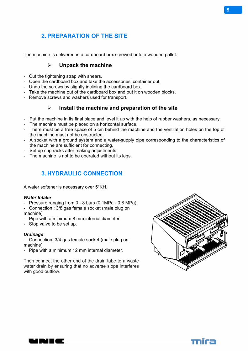
3. HYDRAULIC CONNECTION A water softener is necessary over 5°KH. Water Intake - Pressure ranging from 0 - 8 bars (0.1MPa - 0.8 MPa). - Connection : 3/8 gas female socket (male plug on machine) - Pipe with a minimum 8 mm internal diameter - Stop valve to be set up. Drainage - Connection: 3/4 gas female socket (male plug on machine) - Pipe with a minimum 12 mm internal diameter. Then connect the other end of the drain tube to a waste water drain by ensuring that no adverse slope interferes with good outflow.

6
4. ELECTRIC CONNECTION
- None of the switches must be in ON position. - Make sure that the voltage, frequency and power values marked on the descriptive plate of the
machine are in conformity with the electric network mains.
Power connections
Set the machine switch to Position . The machine is delivered with a cable consisting of 5 numbered wires (including the earth wire). Make sure that the machine connection matches the available voltage network (see wiring diagrams hereunder). Bring the necessary modifications into the supply cable and the plug located near the electrically-driven pressurestat.
Wiring diagrams
N1 L1 L2 L3
N0 1 2 3
MAINCOMMUTATOR
BORNIERTERMINAL PLUG
PRESSOSTATPRESSURESTAT
RESISTANCEHEATING ELEMENT
1 42
63
5
4 5 6 THERMOSTAT SECURITE RESISTANCEHEATING ELEMENT SAFETY THERMOSTAT
1 5 6
1 2 3
P1 P2 P3
CABLECORD
N 2 34
ALIMENTATION BOITIERSELECTRONIQUES ETTRANSFORMATEUR NEONFEEDING ELECTRONICBOXES AND NEONTRANSFORMER
BORNIERTERMINAL PLUG
PRESSOSTATPRESSURESTAT
THERMOSTAT SECURITE RESISTANCEHEATING ELEMENT SAFETY THERMOSTAT
CABLECORD
MAINCOMMUTATOR
BORNIERTERMINAL PLUG
PRESSOSTATPRESSURESTAT
THERMOSTAT SECURITE RESISTANCEHEATING ELEMENT SAFETY THERMOSTAT
CABLECORD
N Ph Ph1 Ph2 Ph3N Ph1 Ph2 Ph3
380 / 400 / 415V TRI + N + 200 / 230 / 240 V MONO + 200 / 230 / 240V TRI +
4 5 6
N L1 PE L3 L2
N 1 2 3
1 42
63
5
4 5 61 2 3
P1 P2 P34 5 6
N 1 2 3
N1 L1 L2 L3
N0 1 2 3
1 42
63
5
4 5 61 2 3
P1 P2 P34 5 6
N 1 2 3
N 1 2 3N 1 2 3
N1 L1 L2 L3
N0 1 2 3
MAINCOMMUTATOR
N 1 2 3
156 4
23
N L1 PE L3 L2
12
56
34N
N L1 PE L3 L2
RESISTANCEHEATING ELEMENT
ALIMENTATION BOITIERSELECTRONIQUES ETTRANSFORMATEUR NEONFEEDING ELECTRONICBOXES AND NEONTRANSFORMER
RESISTANCEHEATING ELEMENT
ALIMENTATION BOITIERSELECTRONIQUES ETTRANSFORMATEUR NEONFEEDING ELECTRONICBOXES AND NEONTRANSFORMER
N = NEUTRE / NEUTRAL 1 = PHASE MARRON / BROWN 2 = PHASE NOIR / BLACK 3 = PHASE GRIS / GREY A : Electronic box B : Switch
IN ALL CASES, THE GREEN/YELLOW WIRE MUST BE EARTHED

7
5. STARTING-UP
Filling the boilers
Turn on the shutoff valve. Plug in the machine. Set the charge switch to Position 1. (Do not set the charge switch to Position 2 until the boiler has been filled).
ON/OFF SWITCH
Steam boiler
- As soon as the machine is turned on, the filling takes place automatically. A safety is programmed, if the filling does not occur before 3 minutes. In this special case, the electrovalve and the pump are cut off. The light blinks. - Check the hydraulic connection of the machine. - Switch off and switch on the machine by setting the charge switch to Position 0 then to position 1. - The filling starts again and lasts 3 minutes.
Internal boilers
- With the filter holder in place, press the continuous/stop key of each unit. As soon as the water flows correctly from the spout (with no air), press the same key again to stop the water.
Heating
When the boilers have been filled, set the charge switch to Position 2. When the operating temperature of the machine is reached, the pressure-gauge must indicate a pressure of 0.9 and 1 bar (0.09MPa et 0.1MPa) (red scale). It is better to keep the machine switched on permanently and the filter-holders inserted in machine even when you are not making coffees.

8
6. CHECKS AND ADJUSTMENTS
To get to the various adjustments, the cup rack, the rear panel or the sides must be removed. Proceed as follows:
CUP RACK: Remove the grids, then undo the 4 upper screws. And remove the cups rack. REAR PANEL(S): Undo the 2 upper screws located inside the machine at its back (under the cup rack); then make the panel(s) glide vertically outwards. SIDES: On each side, undo 1 screw under the front panel; pull the side to the back.
Temperature adjustment by means of the electric pressure controller
The pressure controller (pressurestat) is located at the back. Dismantle the cup rack; remove the cover of the pressure controller to get to its adjustment screw. -TIGHTEN to LOWER the temperature -LOOSEN to RAISE the temperature The pressure-gauge (red scale) must indicate a pressure of between 0.9 and 1 bar which corresponds to a temperature of 120°C (248°F).
Pressure-release valve adjustment MIRA Model The HP valve is located on the right side of the machine: it is necessary to dismantle the sides and the rear panel. The valve is set above the pump; its adjusted pressure must just be greater than the water network pressure. Recommended value: 7 to 8 bar (0.7 to 0.8 MPa) (green scale of the pressure gauge). - If the valve opens ABOVE 8 bar (0.8 MPa): LOOSEN - If the valve opens BELOW 7 bar (0.7MPa): TIGHTEN Use a pin-wrench; after the adjustment, do not forget to block the counter nut.
9
TWIN, TRI and QUATTRO MIRA Models The HP valve is located in the lower part at the left rear of the machine: it is necessary to dismantle the left side. The valve must open at about 13 bar (1.3MPa) (green scale of the pressure gauge). - If the valve opens ABOVE 13 bar (1.3MPa) LOOSEN - If the valve opens BELOW 13 bar (1.3MPa) TIGHTEN Use a pin-wrench; after the adjustment, do not forget to block the counter nut.
Pump-pressure adjustment
In infusion, the pressure must be between 9 and 10 bar (pressure gauge - green scale).
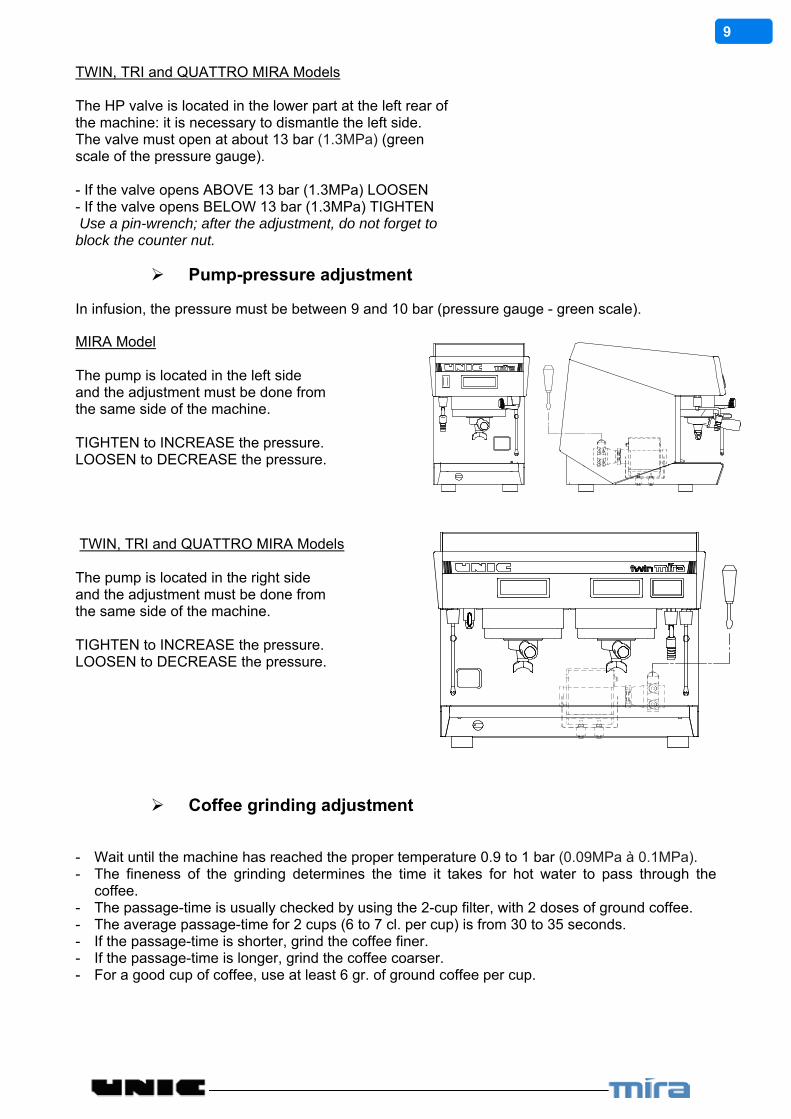
MIRA Model The pump is located in the left side and the adjustment must be done from the same side of the machine. TIGHTEN to INCREASE the pressure. LOOSEN to DECREASE the pressure.
TWIN, TRI and QUATTRO MIRA Models The pump is located in the right side and the adjustment must be done from the same side of the machine. TIGHTEN to INCREASE the pressure. LOOSEN to DECREASE the pressure.
Coffee grinding adjustment
- Wait until the machine has reached the proper temperature 0.9 to 1 bar (0.09MPa à 0.1MPa). - The fineness of the grinding determines the time it takes for hot water to pass through the
coffee. - The passage-time is usually checked by using the 2-cup filter, with 2 doses of ground coffee. - The average passage-time for 2 cups (6 to 7 cl. per cup) is from 30 to 35 seconds. - If the passage-time is shorter, grind the coffee finer. - If the passage-time is longer, grind the coffee coarser. - For a good cup of coffee, use at least 6 gr. of ground coffee per cup.
10
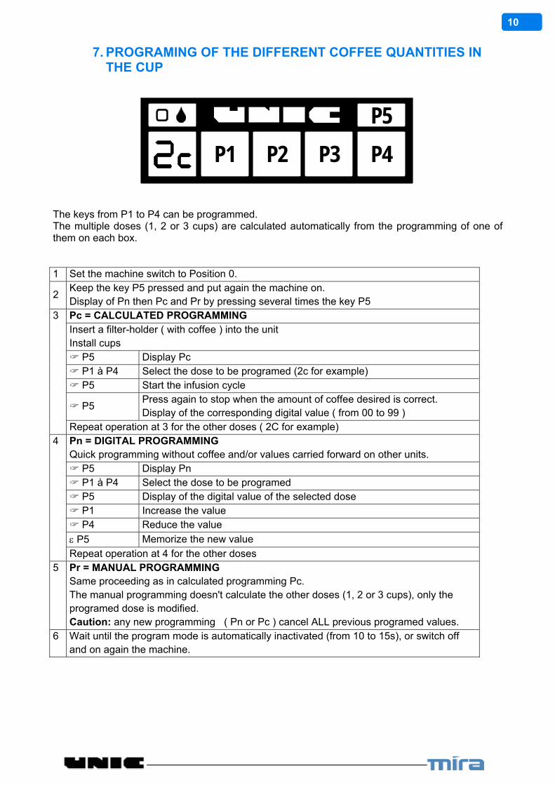
7. PROGRAMING OF THE DIFFERENT COFFEE QUANTITIES IN THE CUP
P1 P2 P3 P4
P5
The keys from P1 to P4 can be programmed. The multiple doses (1, 2 or 3 cups) are calculated automatically from the programming of one of them on each box. 1 Set the machine switch to Position 0.
2 Keep the key P5 pressed and put again the machine on. Display of Pn then Pc and Pr by pressing several times the key P5
3 Pc = CALCULATED PROGRAMMING Insert a filter-holder ( with coffee ) into the unit Install cups P5 Display Pc P1 à P4 Select the dose to be programed (2c for example) P5 Start the infusion cycle
P5 Press again to stop when the amount of coffee desired is correct. Display of the corresponding digital value ( from 00 to 99 )
Repeat operation at 3 for the other doses ( 2C for example) 4 Pn = DIGITAL PROGRAMMING
Quick programming without coffee and/or values carried forward on other units. P5 Display Pn P1 à P4 Select the dose to be programed P5 Display of the digital value of the selected dose P1 Increase the value P4 Reduce the value
P5 Memorize the new value
Repeat operation at 4 for the other doses 5 Pr = MANUAL PROGRAMMING
Same proceeding as in calculated programming Pc. The manual programming doesn't calculate the other doses (1, 2 or 3 cups), only the programed dose is modified. Caution: any new programming ( Pn or Pc ) cancel ALL previous programed values.
6 Wait until the program mode is automatically inactivated (from 10 to 15s), or switch off and on again the machine.
11
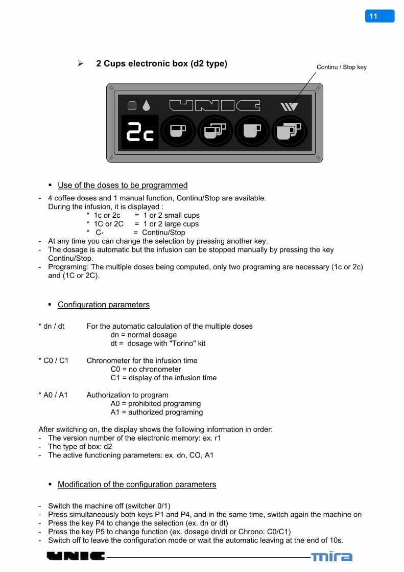
2 Cups electronic box (d2 type)
Use of the doses to be programmed
- 4 coffee doses and 1 manual function, Continu/Stop are available. During the infusion, it is displayed : * 1c or 2c = 1 or 2 small cups * 1C or 2C = 1 or 2 large cups * C- = Continu/Stop
- At any time you can change the selection by pressing another key. - The dosage is automatic but the infusion can be stopped manually by pressing the key
Continu/Stop. - Programing: The multiple doses being computed, only two programing are necessary (1c or 2c)
and (1C or 2C).
Configuration parameters
* dn / dt For the automatic calculation of the multiple doses dn = normal dosage dt = dosage with "Torino" kit * C0 / C1 Chronometer for the infusion time C0 = no chronometer C1 = display of the infusion time * A0 / A1 Authorization to program A0 = prohibited programing A1 = authorized programing After switching on, the display shows the following information in order: - The version number of the electronic memory: ex. r1 - The type of box: d2 - The active functioning parameters: ex. dn, CO, A1
Modification of the configuration parameters
- Switch the machine off (switcher 0/1) - Press simultaneously both keys P1 and P4, and in the same time, switch again the machine on - Press the key P4 to change the selection (ex. dn or dt) - Press the key P5 to change function (ex. dosage dn/dt or Chrono: C0/C1) - Switch off to leave the configuration mode or wait the automatic leaving at the end of 10s.
Continu / Stop key

12
3 Cups electronic box (d3 type)
Use of the doses to be programmed
- 6 coffee doses and 1 manual function, Continu/Stop are available. During the infusion, it is displayed : * 1c, 2c ou 3c = 1, 2 or 3 small cups * 1C, 2C or 3C = 1, 2 or 3 large cups * C- = Continu/Stop - At any time you can change the selection by pressing another key. - The dosage is automatic but the infusion can be stopped manually by pressing the key
Continu/Stop. - To switch from a small dose to a large one (or reverse): press the same key (ex 3C 3c) - Programing: The multiple doses being computed, only two programings are necessary (1c, 2c
or 3c) and (1C, 2C or 3C). If it is necessary, the "Continu" dose can also be programed.
Configuration parameters
* dn / dt For the automatic calculation of the multiple doses dn = normal dosage dt = dosage with "Torino" kit * C0 / C1 Chronometer for the infusion time C0 = no chronometer C1 = display of the infusion time * A0 / A1 Authorization to program A0 = prohibited programing A1 = authorized programing * cc/cC/CC Start of infusion in small or large cup cc = always starts in small cups CC = always starts in large cups cC = keep the last selection: c or C After switching on, the display shows the following information in order: - The version number of the electronic memory: ex. r1 - The type of box: d3 - The active functioning parameters: ex. dn, CO, A1, CC
Modification of the configuration parameters
- Switch the machine off (switcher 0/1) - Press simultaneously both keys P1 and P4, and in the same time, switch again the machine on - Press the key P4 to change the selection (ex. dn or dt) - Press the key P5 to change function (ex. dosage dn/dt or Chrono: C0/C1) - Switch off to leave the configuration mode or wait the automatic leaving at the end of 10s.
Continu / Stop key

13
8. HOT WATER-STEAM BOX, STEAMAIR OPTION
Hot water – steam box
1: led 2: programming key 3: hot water small dose 4: hot water large dose 5: steam dose
Use
� An impulse on the keys 3 to 5 makes the corresponding dose flow: Hot water keys 3 and 4 – Steam key 5. The led lights in green during an hot water dose delivery, in red for a steam dose.
� You can stop before the end of the dose by pushing again the same key. Note: a safety cuts the flow after 105 seconds.
Programming
The programming mode allows the delivery time adjusting for steam and hot water � Keep the key PRO (2) pressed on until the led lights in orange. � Place a container under the appropriate outlet and press the key (3 to 5) to set. � When the level in the container is convenient press again on the same key. � Press on PRO (2) to confirm the new adjustment and come out of the programming mode. Note: the programming mode is automatically switched off after 20 seconds without any action.
SteamAir option The SteamAir option allows, particularly when making cappuccino, to foam the milk very easily and automatically: the supply of air mixed with steam brings milk to a programmed temperature (60° to 70°) and foams it. The stop is done automatically when the temperature is reached which saves milk from boiling. By this way the milk qualities are preserved. Once the air/steam adjustment is defined, the operation is as follows: - Insert the SteamAir outlet into the milk container - Push on the SteamAir key Wait for it to stop automatically. The SteamAir box also controls a timed steam and hot water outlet.
1: led 2: programming key 3: hot water dose 4: steam dose 5: SteamAir

14
Air/steam adjust
SteamAir
Outlet
Components
Outlet cleaning: - Brake down the device and clean it once per day minimum. - After each use, rinse the outlet using the Steam.
Use
Steam and hot water keys: - An impulse on the key activates the corresponding flow delivery. The led lights in green for an hot water dose and in red for a steam dose. - To stop before the end of the delivery, press again the same key Note: a safety stops the flow after 105 seconds for the water and after 180 seconds for the steam. SteamAir key: - Automatic mode: (To reach the programmed T°) One impulse on the key makes the SteamAir flow until the liquid reaches the preset temperature (see § programming) You can stop it manually by pushing again on the key. - Manual mode: (Over the programmed T°) If after the stop in automatic mode (temperature reached) you wish to continue the heating, you have to press again the key. Then you go into manual mode and the outlet is again activated. To stop you will have to push again on the same key. If you don’t do it, it will be stopped automatically by one of the two safeties: after 180 seconds or when the liquid temperature reaches 96° Note: when a safety is switched on, the led blinks.
o oo ooo
Steam only
Level 1 Very fine foam
level 2 Fine foam
level 3 Medium foam
15
Programming
The programming mode allows adjusting the steam and hot water time together with the SteamAir level temperature adjustment. Hot water / steam delay time adjustment: To adjust the hot water and steam delay time you have to: - Switch off the machine by cutting the main switch. - Keep the programming key (2) pressed on, when switching on until orange blink of the led which confirms that you have entered the programming mode. - Place a container under the appropriate outlet and press on the key to set (3 or 4). - When the level in the container is convenient press again on the key. - Press on the programming key (2) to confirm the new adjustment and come out of the programming mode (the led blinks twice in orange). SteamAir temperature adjustment: To adjust the SteamAir temperature, you need (with power on) to: - Maintain the key pressed on until orange blink of the led which confirms that you have entered the programming mode. - Press the SteamAir key paying attention to the number of blinks and colour of the led which shows the temperature adjustment registered: the led lights in orange, it means that the adjustment is as in factory 62°C. A blink corresponds to a difference of 2°C compared to the factory value; with green colour it is below, in red it is above. Examples: 2 green blinks means that the temperature is set to 58°C (62° - 2x 2°) 3 red blinks means that the temperature is set to 68°C (62° + 3x 2°) To modify the adjustment: - Each impulse on hot water key (3) reduces the temperature of 2°, on the steam key (4) increases of 2°. - Press on the SteamAir key to check the adjustment: check the number of blinks looking the colour of the led. - Press on the programming key (2) to confirm the new adjustment and come out of the programming mode (the led blinks twice in orange) Note: The temperature adjustment can be done in a range of 50°C to 90°C (122°F 194°F). The default is 62°C (143.6°F).
16
9. CLEANING AND MAINTENANCE REMEMBER TO CHECK THE WATER TREATMENT SYSTEM PERIODICALLY. DO NOT USE ABRASIVE CLEANERS SCOURING PADS. DO NOT USE CLEANERS CONTAINING BLEACH. THE DESCALING OF THE MACHINE MUST BE DONE BY A QUALIFIED TECHNICIAN. WARNING: The air must circulate freely around
After each use
Steam outlet tube:
After each use, clean the steam tube with a wet rag and push steam push-button for a short moment to eliminate the small amount of liquid that could left inside the tube. (Remove the rod end from steam outlet for easier cleaning).
Daily
Before service or after several hours of inactivity:
Dispense to the drain: - Through each coffee head and water nozzle 0.5 liter of water. - Through each steam nozzle some steam for 1 minute. "BEFORE PREPARING ANY BEVERAGE"
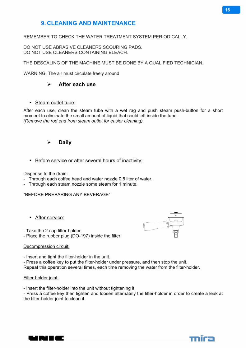
After service:
- Take the 2-cup filter-holder. - Place the rubber plug (DO-197) inside the filter Decompression circuit: - Insert and tight the filter-holder in the unit. - Press a coffee key to put the filter-holder under pressure, and then stop the unit. Repeat this operation several times, each time removing the water from the filter-holder. Filter-holder joint: - Insert the filter-holder into the unit without tightening it. - Press a coffee key then tighten and loosen alternately the filter-holder in order to create a leak at the filter-holder joint to clean it.

17
Filter holder: Take the 2 cups filter holder. Place the rubber plug (DO-197) inside the filter. Put a detergent pellet above the rubber plug then insert and tighten the filter-holder in the unit. - Keep pressed the key then press the
2 large cups * display shows nP - Press again to start the automatic cycle (2s On / 8s Off – x 10 sequences)
*(If the box is set in chronometer mode: Press twice , the second time holding it, then press ). - When the display shows rP: take off the filter-holder from the unit and wait the end of the rinsing cycle (3x 30 seconds) - At the stop of the automatic cycle: put back the filter holder without the plug and without coffee then start a 2 large cups cycle to rinse it.
DHA Option: Use 1 pair of cleaning-rinsing capsules. Inside each introduce 1 Detergent tablet. Close the rotary cover. Engage the 2 capsules inside the holder. Close the DHA.
-Keep pressed the key then press the
2 large cups * display shows nP - Press again to start the automatic cycle (2s On / 8s Off – x 10 cleaning sequences follows by 3x 30 seconds of rinsing)
*(If the box is set in chronometer mode: Press twice , the second time holding it, then press ). At the stop of rinsing cycle, remove the capsules (be careful of the hot water inside)
Weekly
Cleaning with detergent tablet (automatic cycle)
18
Filter holder
Wash the filter-holders and the filters (removing the filter) in soapy water.
Overflow tray:
Remove the overflow tray to empty it and rinse it under the tap.
Body:
Clean the body of the machine using a soft cloth and alcohol for the stainless-steel parts and a non-abrasive detergent for the painted parts.

19
Water Softener Two water softener suppliers are available at UNIC SA. BRITA ® BESTMAX ™ Test the water hardness of the network and refer to the technical documentation of the water softener used for optimum adjustment. Note: A softener must be changed every 1 year, even if it does not reach the end of its filtering capacity.
20
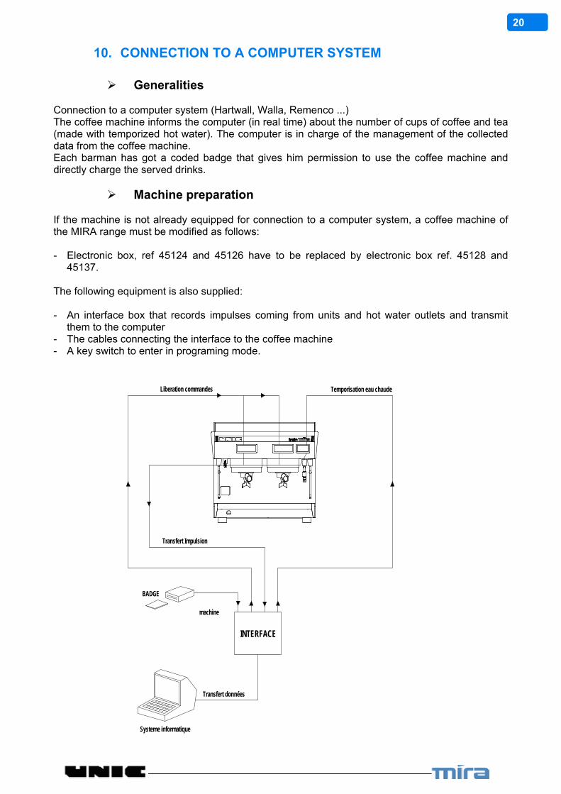
10. CONNECTION TO A COMPUTER SYSTEM Generalities
Connection to a computer system (Hartwall, Walla, Remenco ...) The coffee machine informs the computer (in real time) about the number of cups of coffee and tea (made with temporized hot water). The computer is in charge of the management of the collected data from the coffee machine. Each barman has got a coded badge that gives him permission to use the coffee machine and directly charge the served drinks.
Machine preparation
If the machine is not already equipped for connection to a computer system, a coffee machine of the MIRA range must be modified as follows: - Electronic box, ref 45124 and 45126 have to be replaced by electronic box ref. 45128 and
45137. The following equipment is also supplied: - An interface box that records impulses coming from units and hot water outlets and transmit
them to the computer - The cables connecting the interface to the coffee machine - A key switch to enter in programing mode.
INTERFACE
BADGE
Liberation commandes
Transfert Impulsion
Temporisation eau chaude
Systeme informatique
Transfert données
machine

21
TROUBLE SHOOTING
VERY IMPORTANT! BEFORE TAKING ANY ACTION MAKE SURE THAT ALL THE ADJUSTMENTS ARE CORRECT. - TEMPERATURE 120°C STEAM PRESSURE 0,9 to 1 bar (14 PSI) - INFUSION PRESSURE 9 to 10 bar (140 PSI) High pressure valve opening: over 13 bar (188 PSI) - WATER SUPPLY PRESSURE 0 bar to 6 bar (0 PSI to 90 PSI) If the machine "sucks" water directly from an external reservoir, check the water level in the
reservoir and the non-return valve and filter fixed at the end of the inlet pipe. - PRECAUTIONS TO BE TAKEN
A. Switch off the machine before any action on the electric circuits.
B. Cool the machine and make the pressures down before any action on the hydraulic circuit.

22
11. DISPLAYED FAILURES
Push button 1
Push button 2 Push button 3 Push button 4 Push button 5
See on § Problems in connection with the electronic boxes’ control button (page 24)
Fuse
See on § Fuse problems (page 24)
Time
See on § Dosage problems (page 25) > 105 sec
Metering + Time
Dosage Metering
See on § Metering safety system (page 26) > 105 sec
See on § Metering safety system (page 26)
Short circuit Metering
Opened Metering
See on § Dosing device safety system (page 27)
23
Problems in connection with the electronic boxes’ control button
If it is displayed P1, P2 ... or P5, this means that the corresponding key is in short-circuit and can't be used any more.
Remedy: - Check that the front is not deformed - Change the electronic box
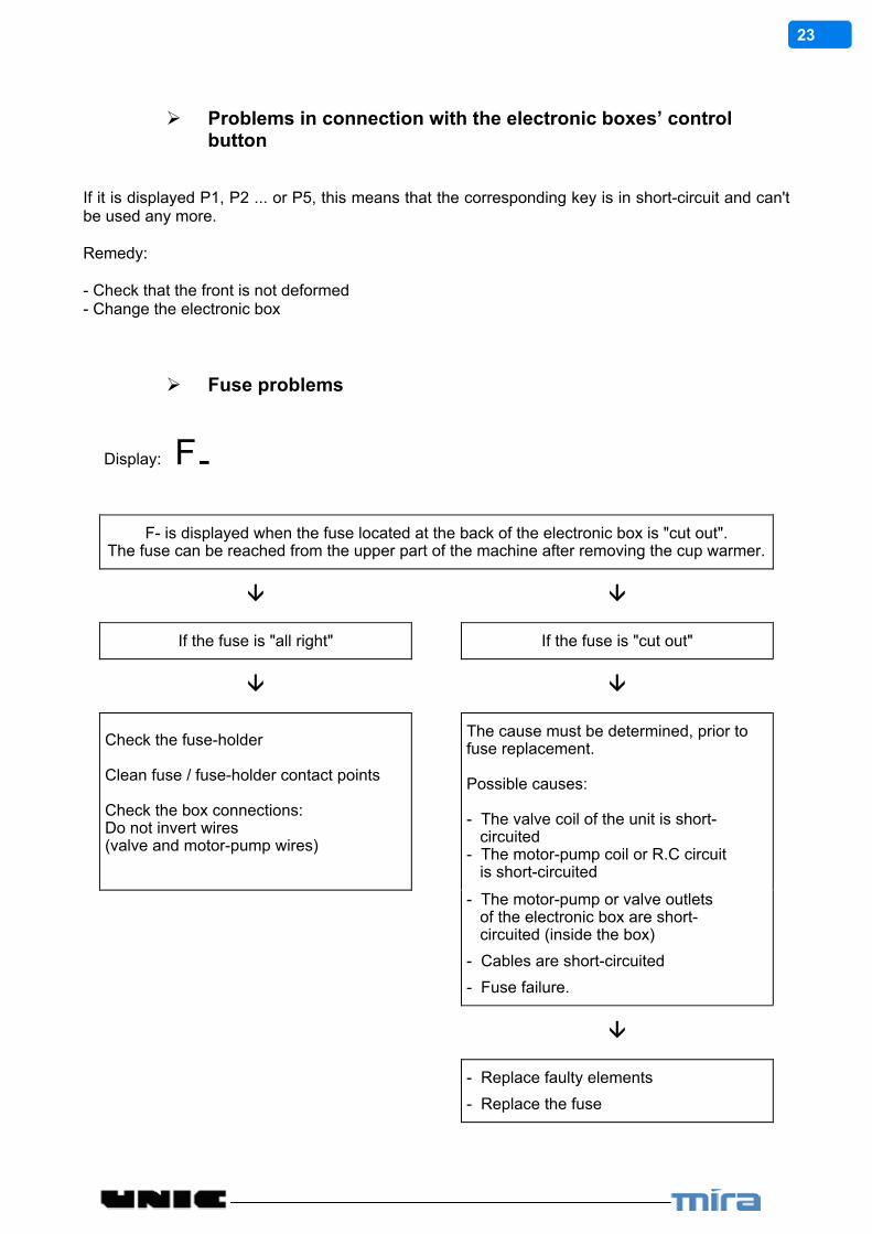
Fuse problems
Display: F-
F- is displayed when the fuse located at the back of the electronic box is "cut out". The fuse can be reached from the upper part of the machine after removing the cup warmer.
If the fuse is "all right" If the fuse is "cut out"
Check the fuse-holder Clean fuse / fuse-holder contact points Check the box connections: Do not invert wires (valve and motor-pump wires)
The cause must be determined, prior to fuse replacement. Possible causes: - The valve coil of the unit is short- circuited - The motor-pump coil or R.C circuit is short-circuited
- The motor-pump or valve outlets of the electronic box are short- circuited (inside the box)
- Cables are short-circuited
- Fuse failure.
- Replace faulty elements
- Replace the fuse
24
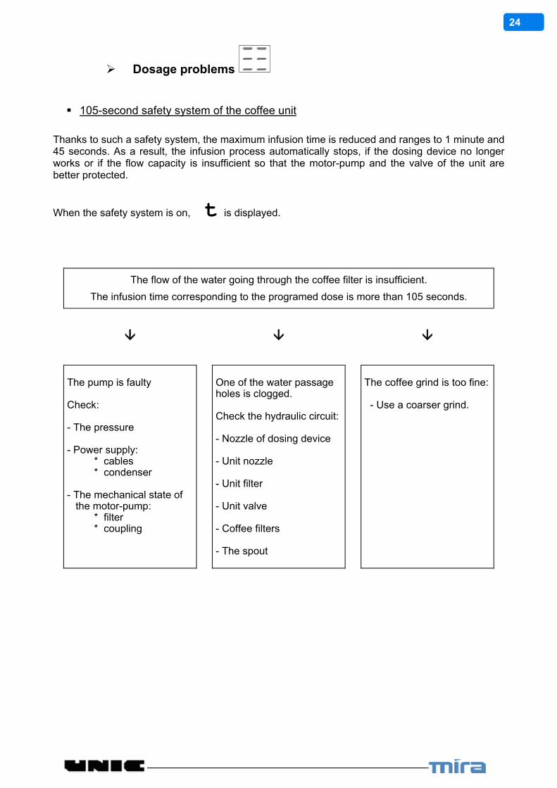
Dosage problems
105-second safety system of the coffee unit
Thanks to such a safety system, the maximum infusion time is reduced and ranges to 1 minute and 45 seconds. As a result, the infusion process automatically stops, if the dosing device no longer works or if the flow capacity is insufficient so that the motor-pump and the valve of the unit are better protected.
When the safety system is on, t is displayed.
The flow of the water going through the coffee filter is insufficient.
The infusion time corresponding to the programed dose is more than 105 seconds.
The pump is faulty Check: - The pressure - Power supply: * cables * condenser - The mechanical state of the motor-pump: * filter * coupling
One of the water passage holes is clogged. Check the hydraulic circuit: - Nozzle of dosing device - Unit nozzle - Unit filter - Unit valve - Coffee filters - The spout
The coffee grind is too fine: - Use a coarser grind.
25
Metering safety system
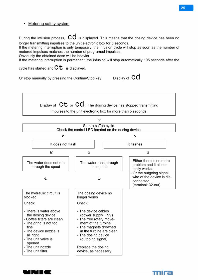
During the infusion process, cd is displayed. This means that the dosing device has been no
longer transmitting impulses to the unit electronic box for 5 seconds. If the metering interruption is only temporary, the infusion cycle will stop as soon as the number of metered impulses matches the number of programed impulses. Obviously the obtained dose will be heavier. If the metering interruption is permanent, the infusion will stop automatically 105 seconds after the
cycle has started and ct is displayed.
Or stop manually by pressing the Continu/Stop key. Display of cd
Display of ct or cd . The dosing device has stopped transmitting
impulses to the unit electronic box for more than 5 seconds.
Start a coffee cycle.Check the control LED located on the dosing device.
It does not flash It flashes
The water does not run through the spout
The water runs through the spout
- Either there is no more problem and it all nor- mally works.
- Or the outgoing signal
wire of the device is dis- connected. (terminal: 32-out)
The hydraulic circuit is blocked
The dosing device no longer works
Check: - There is water above the dosing device - Coffee filters are clean - The grind is not too fine - The device nozzle is all right - The unit valve is opened - The unit nozzle - The unit filter.
Check: - The device cables (power supply + 9V) - The free rotary move- ment of the turbine - The magnets drowned in the turbine are clean - The dosing device (outgoing signal) Replace the dosing device, as necessary.
26
Dosing device safety system
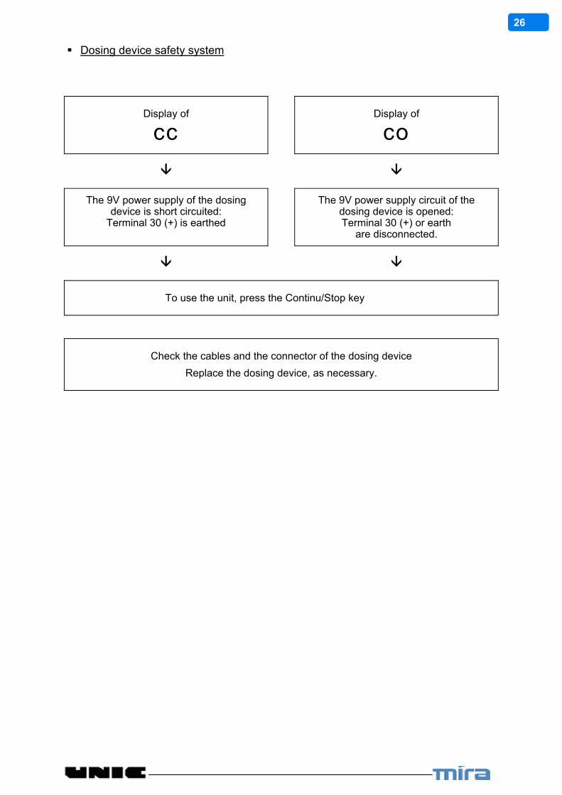
Display of
cc
Display of
co
The 9V power supply of the dosing device is short circuited:
Terminal 30 (+) is earthed
The 9V power supply circuit of the dosing device is opened: Terminal 30 (+) or earth
are disconnected.
To use the unit, press the Continu/Stop key
Check the cables and the connector of the dosing device
Replace the dosing device, as necessary.
27
12. OTHER FAILURES
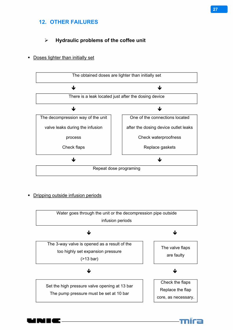
Hydraulic problems of the coffee unit
Doses lighter than initially set
The obtained doses are lighter than initially set
There is a leak located just after the dosing device
The decompression way of the unit
valve leaks during the infusion
process
Check flaps
One of the connections located
after the dosing device outlet leaks
Check waterproofness
Replace gaskets
Repeat dose programing
Dripping outside infusion periods
Water goes through the unit or the decompression pipe outside
infusion periods
The 3-way valve is opened as a result of the
too highly set expansion pressure
(>13 bar)
The valve flaps
are faulty
Set the high pressure valve opening at 13 bar
The pump pressure must be set at 10 bar
Check the flaps
Replace the flap
core, as necessary.

28
An insufficient infusion pressure
The infusion pressure is lower than 10 bar
Set the pump as indicated on ( § 5.3 )
Setting operations are unsuccessful
The pump is faulty The motor-pump is The motor-pump is no
- dirty filter mechanically blocked longer power-supplied
- coil condenser - damaged pallets (the thermal safety sys- - broken coupling tem and the circuit- - faulty by-pass breaker protecting the motor coil) Check the cable
- Disassemble and restore the pump to its initial condition - Reset pressure
A wrong decompression process
When the infusion process is over, you remove the filter-holder and you notice the grounds pancake is wet.
Check: - The temperature is too low - Steam pressure - The infusion time is too short - Grind (A too coarse grind - a too - Ground coffee dose light dose - a too low pressure) - Pump pressure - The decompression circuit is blocked - Spray - Filter - Solenoid valve

29
Problems in connections with the level regulation
The steam boiler is flooded
The steam boiler is flooded
Problem generated by the Problem generated by the filling valve water level probe
* The filling valve flap is no
longer in place and generates leaks: fur or any other obstacle...
The probe is covered with an insulating agent (scale) or the
probe wire is cut out
* The filling valve relay got stuck Clean probes and check
cables
* Replace gaskets and clean the
filling valve surface
* Replace the electric valve or the
leval box, as necessary.
The boiler is empty
RISK TO RUIN THE HEATING ELEMENT
The probe is directly earthed
The filling valve is not ON or its coil is burnt out
Check: - the probe wire - the valve cable - the electronic box functioning - the valve Replace as necessary
Check the state of the heating element
30
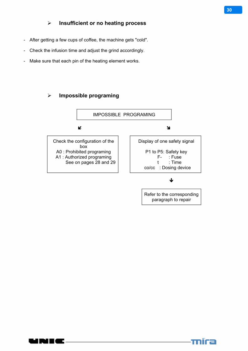
Insufficient or no heating process
- After getting a few cups of coffee, the machine gets "cold". - Check the infusion time and adjust the grind accordingly. - Make sure that each pin of the heating element works.
Impossible programing
IMPOSSIBLE PROGRAMING
Check the configuration of the box
A0 : Prohibited programing A1 : Authorized programing
See on pages 28 and 29
Display of one safety signal
P1 to P5 : Safety key F- : Fuse t : Time
co/cc : Dosing device
Refer to the corresponding paragraph to repair
31
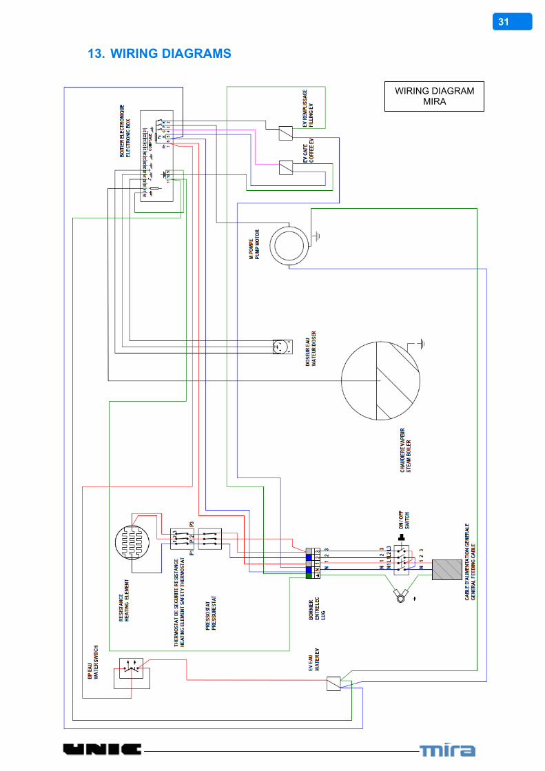
13. WIRING DIAGRAMS
WIRING DIAGRAM MIRA

32
WIRING DIAGRAM TWIN MIRA

33
WIRING DIAGRAM TWIN MIRA
380-400-415 V Tri 50/60HZ+N+TERRE
34
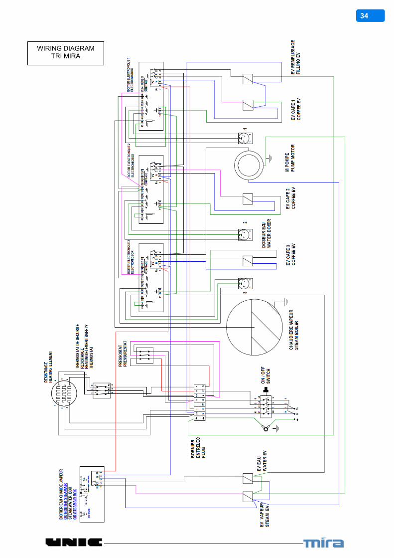
WIRING DIAGRAM TRI MIRA

35
WIRING DIAGRAM TRI MIRA
380-400-415 V Tri 50/60HZ+N+TERRE
36
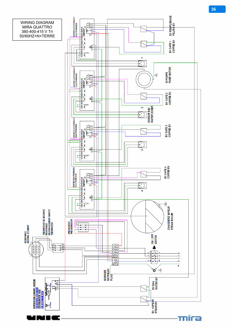
WIRING DIAGRAM MIRA QUATTRO 380-400-415 V Tri
50/60HZ+N+TERRE
37
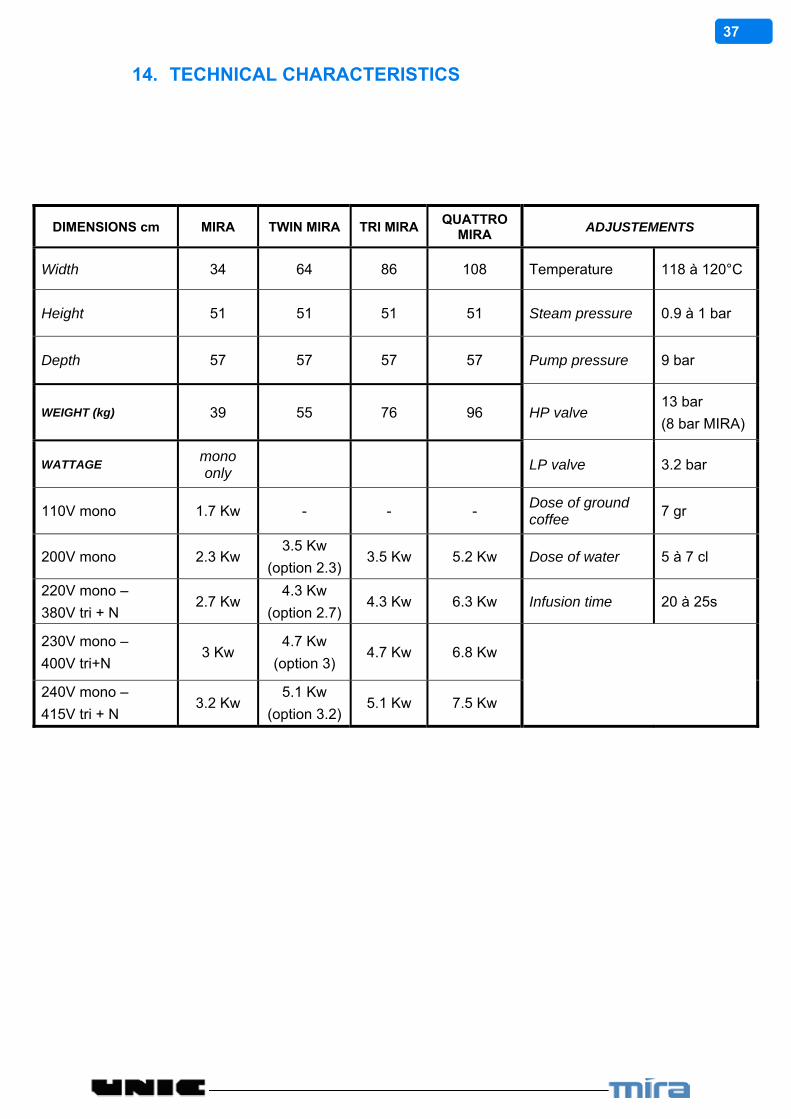
14. TECHNICAL CHARACTERISTICS
DIMENSIONS cm MIRA TWIN MIRA TRI MIRA QUATTRO
MIRA ADJUSTEMENTS
Width 34 64 86 108 Temperature 118 à 120°C
Height 51 51 51 51 Steam pressure 0.9 à 1 bar
Depth 57 57 57 57 Pump pressure 9 bar
WEIGHT (kg) 39 55 76 96 HP valve 13 bar
(8 bar MIRA)
WATTAGE mono only
LP valve 3.2 bar
110V mono 1.7 Kw - - - Dose of ground coffee
7 gr
200V mono 2.3 Kw 3.5 Kw
(option 2.3) 3.5 Kw 5.2 Kw Dose of water 5 à 7 cl
220V mono –
380V tri + N 2.7 Kw
4.3 Kw
(option 2.7) 4.3 Kw 6.3 Kw Infusion time 20 à 25s
230V mono –
400V tri+N 3 Kw
4.7 Kw
(option 3) 4.7 Kw 6.8 Kw
240V mono –
415V tri + N 3.2 Kw
5.1 Kw
(option 3.2) 5.1 Kw 7.5 Kw