rbs 6501 installing
DESCRIPTION
RBS 6501 InstallingTRANSCRIPT
Installing RBSRBS 6501
INSTALLATION INSTRUCTIONS
31/1531-LZA 701 6001 Uen D

Contents
Contents
1 Introduction 1
2 Prerequisite 2
2.1 Documentation 2
2.2 Equipment 2
2.3 Conditions 4
2.4 Resting the RBS 5
3 Unpacking and Checking Materials 6
4 Preparing for Installation 7
4.1 Scanning Barcode 7
4.2 Installing the Cover Plate (Optional) 7
4.3 Attaching the Front Solar Shield 8
4.4 Installing Mounting Bolts 8
4.5 Mounting the TX-Monitor (Optional) 8
4.6 Mounting the Semi-integrated Omni Antennas (Optional) 9
5 Installing Mounting Brackets 10
5.1 Direct Mounting 10
5.2 Using mUnit Base Mount (Optional) 11
6 Mounting the RBS 13
7 Connecting the Cables 15
7.1 Opening the Tamper-proof Cover 15
7.2 Connecting the Non-RF Cables 16
7.3 Connecting the RF Cables 18
8 Powering Up the RBS 20
9 Commissioning the RBS 21
9.1 Performing Auto-Integration without a Laptop 21
9.2 Connecting to the Client 21
10 Verifying RBS Installation on Site 23
11 Performing Concluding Routines 24
31/1531-LZA 701 6001 Uen D | 2014-03-10

Installing RBS
12 Appendix A: Optional Actions 26
12.1 Installing the Semi-integrated Omni Antennas 26
12.2 Connecting RF Cables with a TX-Monitor 28
12.3 Installing the Cover Plate 30
13 Appendix B: Working at Height 32
Reference List 33
31/1531-LZA 701 6001 Uen D | 2014-03-10

Introduction
1 Introduction
This document describes how to install the RBS 6501 on site and how toconnect it to external interfaces.
Figure 1 shows the work process.
Ge3583A
Mounting the RBS
Verifying RBS Installation on Site
Unpacking and Checking the Materials
Preparing for Installation
Direct Mounting on a Pole or a Wall
Connecting Cables
Powering up
Performing Concluding Routines
mUnit Base Mounton a Pole or a Wall (Optional)
Commissioning the RBS
Mounting the TX-Monitor (Optional)
Installing the Semi-Integrated Omni Antennas (Optional)
Figure 1 RBS Installation Flow
131/1531-LZA 701 6001 Uen D | 2014-03-10
Installing RBS
2 Prerequisite
This section contains information about the documentation, tools, equipment,and conditions required for the installation procedure.
2.1 Documentation
Ensure that the following documents are read and understood:
• Person Health and Safety Information
• System Safety Information
• Transportation and Storage
• Integrating RBSs On-Site Using ENIS
See Reference List for required documents.
2.2 Equipment
The required and optional equipment for the installation of the RBS are listed inTable 1.
2 31/1531-LZA 701 6001 Uen D | 2014-03-10
Prerequisite
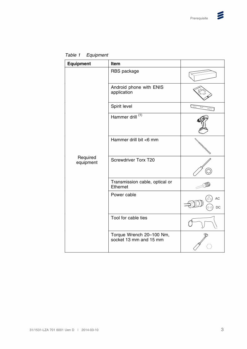
Table 1 Equipment
Equipment Item
RBS package
Android phone with ENISapplication
Spirit level
Hammer drill (1)
Hammer drill bit <6 mm
Screwdriver Torx T20
Transmission cable, optical orEthernet
Power cableAC
DC
Tool for cable ties
Requiredequipment
Torque Wrench 20–100 Nm,socket 13 mm and 15 mm
331/1531-LZA 701 6001 Uen D | 2014-03-10
Installing RBS
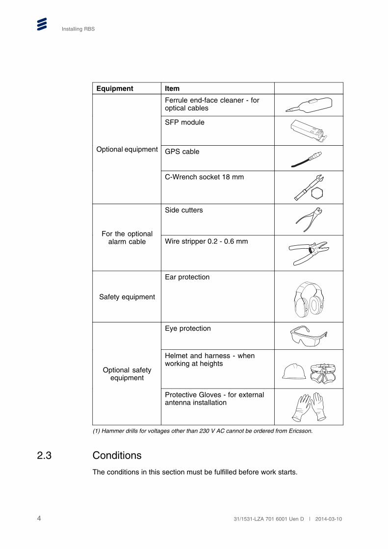
Equipment Item
Ferrule end-face cleaner - foroptical cables
SFP module
GPS cableOptional equipment
C-Wrench socket 18 mm
Side cutters
For the optionalalarm cable Wire stripper 0.2 - 0.6 mm
Safety equipment
Ear protection
Eye protection
Helmet and harness - whenworking at heights
Optional safetyequipment
Protective Gloves - for externalantenna installation
(1) Hammer drills for voltages other than 230 V AC cannot be ordered from Ericsson.
2.3 Conditions
The conditions in this section must be fulfilled before work starts.
4 31/1531-LZA 701 6001 Uen D | 2014-03-10

Prerequisite
2.3.1 Before Going to the Site
Before going to site, make sure the site access permission has been received.
2.3.2 Before Starting the Installation
Before starting the installation, ensure the following:
• The site is prepared in accordance with the Site Installation Documentation.
• Ordered hardware is available.
• The site power supply (-48 V DC or 100–250 V AC) for the RBS is installedand tested at the RBS site.
• Site earthing is installed and tested.
• Site materials are installed and checked as specified in the relevant sitematerial installation instructions.
• For protection of the RBS, one of the following alternatives must beinstalled and tested:
� A main switch and an external fuse
� A circuit breaker
• If an external antenna is used, the antenna system is installed and tested.
2.4 Resting the RBS
Always rest the RBS on a flat surface to protect the connectors, as shownin Figure 2.
Ge2152B
Figure 2 Resting the RBS
531/1531-LZA 701 6001 Uen D | 2014-03-10
Installing RBS
3 Unpacking and Checking Materials
To unpack and check the materials:
1. Check that the items delivered correspond to the packing list.
2. Examine the RBS for damage. For more information, refer to HandlingFaulty Equipment.
6 31/1531-LZA 701 6001 Uen D | 2014-03-10

Preparing for Installation
4 Preparing for Installation
This section provides information for preparations before installing the RBS.
4.1 Scanning Barcode
Scan the barcode on the RBS using the ENIS Android application with a smartphone. For more information, refer to Integrating RBSs On-Site Using ENIS.
Ge3811A
Figure 3 Scan Barcode
4.2 Installing the Cover Plate (Optional)
If an external RF antenna is needed but the RBS with internal antenna isordered, remove the internal antenna and install the cover plate to prevent thewater intrusion, for more information, see Section 12.3 on page 30.
731/1531-LZA 701 6001 Uen D | 2014-03-10

Installing RBS
4.3 Attaching the Front Solar Shield
Ge3443A
2
1
55-70 mm
1
Figure 4 Attach the Front Solar Shield
To attach the front solar shield:
1. Place the front solar shield on the RBS.
2. Slide down the front solar shield until it snaps into the closed position.
4.4 Installing Mounting Bolts
Insert the four M8 screws in the RBS and fasten them by hand, leaving 8 mm ofthe bolt pointing out from the RBS.
Ge2270C
Figure 5 Install Mounting Bolts
4.5 Mounting the TX-Monitor (Optional)
The TX-monitor needs to be mounted on the RBS mounting plate beforeinstalling the RBS.
For instructions on how to mount the TX-monitor, refer to Quick Guide (TXMonitor Package, mRBS).
8 31/1531-LZA 701 6001 Uen D | 2014-03-10
Preparing for Installation
4.6 Mounting the Semi-integrated Omni Antennas(Optional)
The semi-integrated omni antennas need to be mounted on the RBS mountingplate before installing the RBS.
Follow the instructions described in Section 12.1.1 on page 26.
931/1531-LZA 701 6001 Uen D | 2014-03-10
Installing RBS
5 Installing Mounting Brackets
This section describes how to mount the brackets for installing the RBS.
Note: The procedure of mounting the RBS on a ceiling, roof, or floor is thesame as the wall mounting procedure.
5.1 Direct Mounting
This section describes how to directly mount the RBS to a pole or a wall byusing the RBS mounting plate.
5.1.1 Pole Mounting with Hose Clamps
Ge4361A
1 2
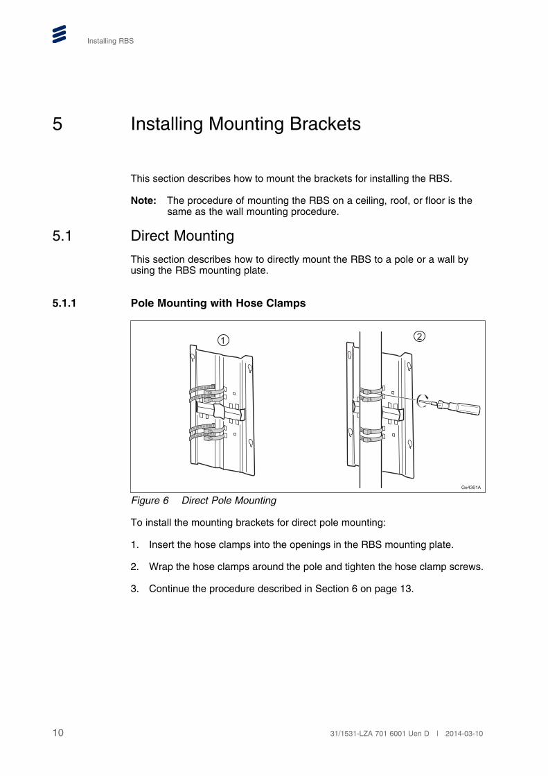
Figure 6 Direct Pole Mounting
To install the mounting brackets for direct pole mounting:
1. Insert the hose clamps into the openings in the RBS mounting plate.
2. Wrap the hose clamps around the pole and tighten the hose clamp screws.
3. Continue the procedure described in Section 6 on page 13.
10 31/1531-LZA 701 6001 Uen D | 2014-03-10

Installing Mounting Brackets
5.1.2 Wall Mounting
Ge4359A
1 2
Figure 7 Direct Wall Mounting
To install the mounting plate directly on a wall:
1. Drill four holes in the wall. The dimensions of the two directions are:
• Short side: 180 mm
• Long side: 385 mm
2. Mount the RBS mounting plate with suitable fasteners.
Note: Wall fasteners, such as screws or anchors, are not included in thedelivery package.
3. Continue the procedure described in Section 6 on page 13.
5.2 Using mUnit Base Mount (Optional)
This section describes how to install the RBS by using the mUnit base mount.
1131/1531-LZA 701 6001 Uen D | 2014-03-10

Installing RBS
5.2.1 Preparation
Ge3571A
15 mm
44 Nm
1 2
Figure 8 Using mUnit Base Mount
To install the mUnit base mount to the RBS mounting plate:
1. Insert the four screws to the mounting plate and then tighten the nuts byhand, leaving 8 mm of the bolt pointing out from the plate.
2. Hook the base mount onto the mounting plate and tighten the four nuts.
5.2.2 Mounting Brackets on a Pole or Wall
For more information, refer to one of the following documents:
• Pole mounting: mUnit Pole Clamp
• Wall mounting: mUnit Base Mount
12 31/1531-LZA 701 6001 Uen D | 2014-03-10

Mounting the RBS
6 Mounting the RBS
Warning!
Risk for falling objects, work at height in progress. Falling objects can causeserious injury or even be fatal. Always wear a helmet and avoid standing inthe danger area.
To mount the RBS:
1. If needed, hoist the RBS up to its position on the pole or wall while guidingthe RBS using the lower rope.
Ge2733B
2. Hook the RBS onto the mounting plate and tighten the four screws.
1331/1531-LZA 701 6001 Uen D | 2014-03-10

Installing RBS
Ge3603A
13 mm
18 Nm
Pole Intallation Wall Intallation
14 31/1531-LZA 701 6001 Uen D | 2014-03-10

Connecting the Cables
7 Connecting the Cables
This section describes how to connect the cables for the RBS.
7.1 Opening the Tamper-proof Cover
This section describes how to handle the solar shield and tamper-proof coverfor installation.
1. To open the front solar shield:
a Press the bottom center of the front solar shield by using both hands.
b Push the front solar shield upwards, until it snaps into the position.
GE3587B
2
a b
2. Loosen the two captive screws, but do not completely remove them.
GE3445A
Torx T20
3. Open the tamper-proof cover, and snap it into the open position.
1531/1531-LZA 701 6001 Uen D | 2014-03-10

Installing RBS
GE3576A
7.2 Connecting the Non-RF Cables
Ge3431A
GPS ANT GPS -48V D TN B TN A LMT EC/
2 AC
DC
- 48V
Figure 9 Connection Interfaces
Note: For information on the field-made cables and the cable pin connections,refer to RBS Description.
To connect the Non-RF cables:
1. Connect the earthing cable to the earthing bolt.
16 31/1531-LZA 701 6001 Uen D | 2014-03-10

Connecting the Cables
GE3429A
24 Nm
Socket 13 mm
nut
toothed lock washer
flat washer
2. Remove the protective caps from the ports to be connected, and keep themin an appropriate place for future use.
3. (Optional) Connect the QMA connector of the GPS RF cable to the portmarked GPS ANT, and push it by hand.
4. (Optional) Connect the GPS cable to the port marked GPS.
5. (Optional) Connect the DC out power cable to the port marked -48 V.
6. (Optional) Connect the optical cables to the port marked D port byperforming the following procedure:
Note: Instructions for installation of the optical cables can be found inInstalling Optical Cables for Main-Remote Solutions.
GE3439A
a
b
a Insert the SFP module into the optical cable.
b Insert the SFP module into the SFP cage in the port and thensnap the cable connector to the lock position.
7. Use one of the following two connection options:
• TNB – Connect the Ethernet optical cable for optical transmission. Seethe procedure described in Step 6.
• TNA – Connect the RJ-45 cable for electrical transmission.
1731/1531-LZA 701 6001 Uen D | 2014-03-10
Installing RBS
8. (Optional) Connect the external alarm cable to the port marked EC/ .
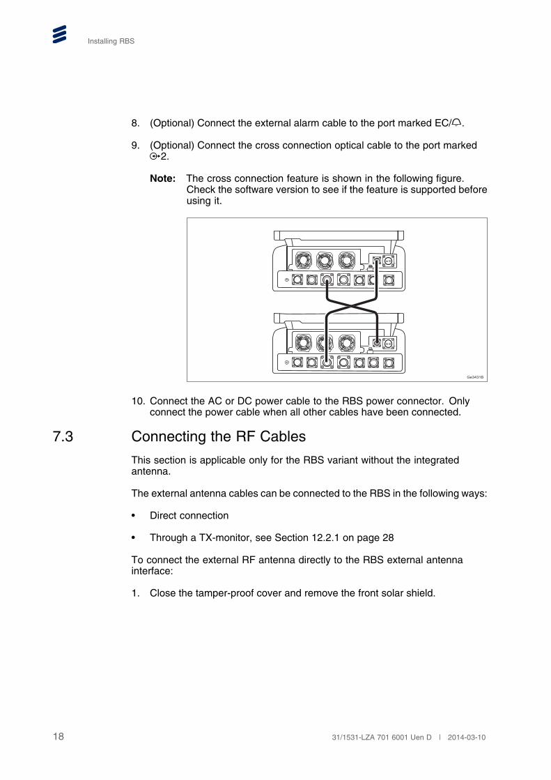
9. (Optional) Connect the cross connection optical cable to the port marked2.
Note: The cross connection feature is shown in the following figure.Check the software version to see if the feature is supported beforeusing it.
Ge3431B
10. Connect the AC or DC power cable to the RBS power connector. Onlyconnect the power cable when all other cables have been connected.
7.3 Connecting the RF Cables
This section is applicable only for the RBS variant without the integratedantenna.
The external antenna cables can be connected to the RBS in the following ways:
• Direct connection
• Through a TX-monitor, see Section 12.2.1 on page 28
To connect the external RF antenna directly to the RBS external antennainterface:
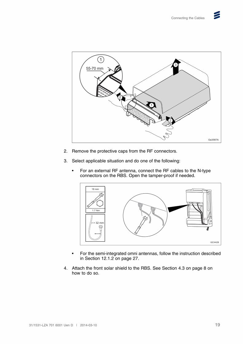
1. Close the tamper-proof cover and remove the front solar shield.
18 31/1531-LZA 701 6001 Uen D | 2014-03-10
Connecting the Cables
Ge3587A
2
3
2
2
1
55-70 mm
1
2. Remove the protective caps from the RF connectors.
3. Select applicable situation and do one of the following:
• For an external RF antenna, connect the RF cables to the N-typeconnectors on the RBS. Open the tamper-proof if needed.
GE3442B
18 mm
1.7 Nm
r > 32 mm
• For the semi-integrated omni antennas, follow the instruction describedin Section 12.1.2 on page 27.
4. Attach the front solar shield to the RBS. See Section 4.3 on page 8 onhow to do so.
1931/1531-LZA 701 6001 Uen D | 2014-03-10
Installing RBS
8 Powering Up the RBS
The RBS must be powered up within 48 hours after installation, even if theRBS is not put into service. The reason is to protect the internal units fromlocal climate conditions.
Do!
Products not connected to the ground risk being damaged by overvoltageor overcurrent. Always connect products to the ground as specified in theinstructions.
To power up the RBS:
1. Ensure that the polarities are correct in the power connector.
2. Switch on the site power.
20 31/1531-LZA 701 6001 Uen D | 2014-03-10
Commissioning the RBS
9 Commissioning the RBS
This section describes how to set up the RBS by using a smart phone ora laptop.
9.1 Performing Auto-Integration without a Laptop
The RBS commission can be performed by using the ENIS Android applicationwith a smart phone, refer to Integrating RBSs On-Site Using ENIS.
9.2 Connecting to the Client
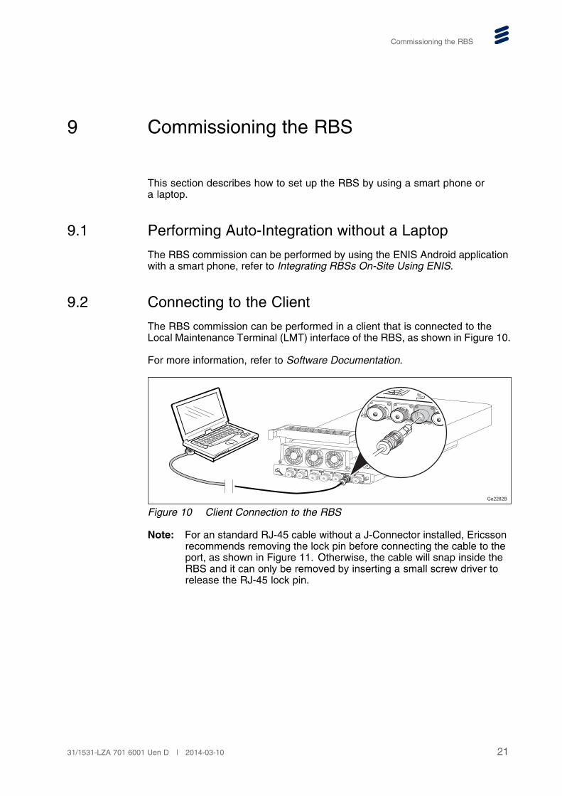
The RBS commission can be performed in a client that is connected to theLocal Maintenance Terminal (LMT) interface of the RBS, as shown in Figure 10.
For more information, refer to Software Documentation.
Ge2282B
Figure 10 Client Connection to the RBS
Note: For an standard RJ-45 cable without a J-Connector installed, Ericssonrecommends removing the lock pin before connecting the cable to theport, as shown in Figure 11. Otherwise, the cable will snap inside theRBS and it can only be removed by inserting a small screw driver torelease the RJ-45 lock pin.
2131/1531-LZA 701 6001 Uen D | 2014-03-10

Installing RBS
P013452B
Figure 11 Standard RJ-45 Cable without a J-Connector
After performing the initial commission, remove the cable from the LMTinterface and refit the protective cap.
22 31/1531-LZA 701 6001 Uen D | 2014-03-10
Verifying RBS Installation on Site
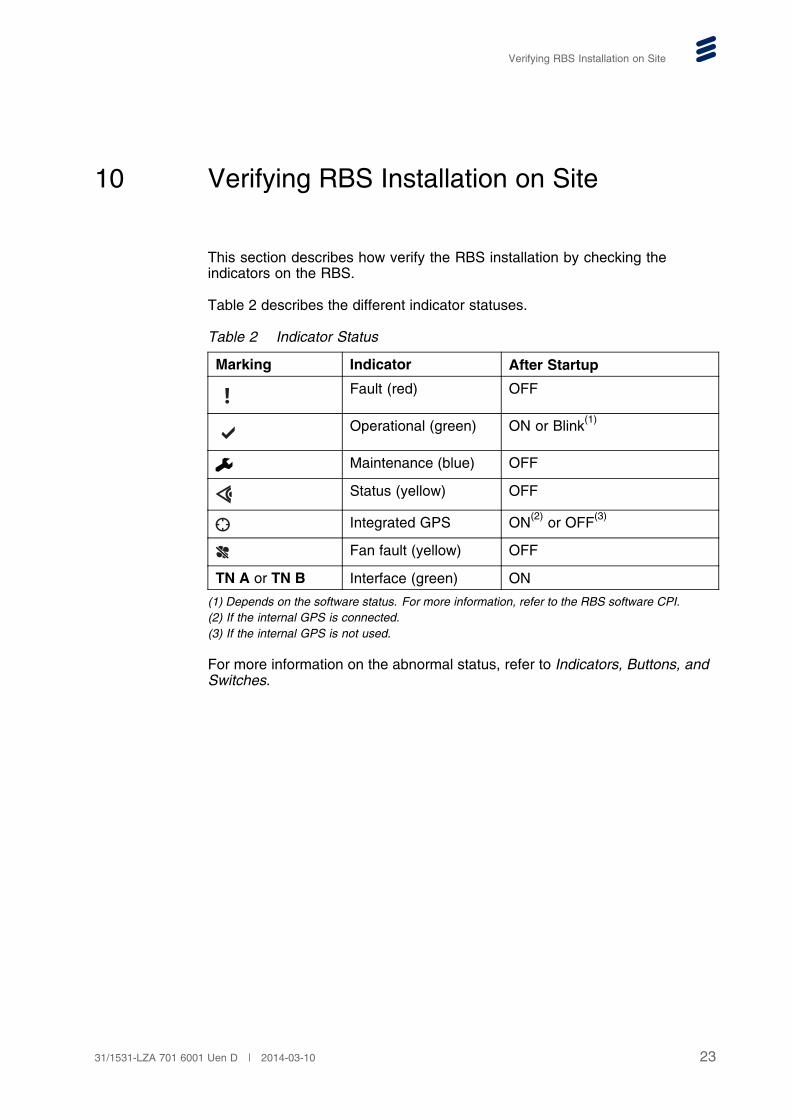
10 Verifying RBS Installation on Site
This section describes how verify the RBS installation by checking theindicators on the RBS.
Table 2 describes the different indicator statuses.
Table 2 Indicator Status
Marking Indicator After Startup
Fault (red) OFF
Operational (green) ON or Blink(1)
Maintenance (blue) OFF
Status (yellow) OFF
Integrated GPS ON(2) or OFF(3)
Fan fault (yellow) OFF
TN A or TN B Interface (green) ON
(1) Depends on the software status. For more information, refer to the RBS software CPI.(2) If the internal GPS is connected.(3) If the internal GPS is not used.
For more information on the abnormal status, refer to Indicators, Buttons, andSwitches.
2331/1531-LZA 701 6001 Uen D | 2014-03-10

Installing RBS
11 Performing Concluding Routines
Before leaving the site:
1. It is recommended to use a self-amalgamating (self-fusing) tape to securethe power cable.
Ge1105C
30 m
m
50 m
m
a b
a Start applying the tape approximately 50 mm below the lower edge ofeach connector. Overlap each turn by 50%. Proceed all the way up tothe edge of the connector.
Note: Vary the stretching of the tape and avoid spaces.
b Apply two, half-overlapped, slightly-stretched layers of insulatingtape. For each layer, start 30 mm below the lower end of theself-amalgamating (self-fusing) tape and proceed all the way up tothe edge of the connector.
2. Strap the cables to the pole, mast or wall.
3. Close the tamper-proof cover and tighten the two captive screws. Thenclose the front solar shield.
24 31/1531-LZA 701 6001 Uen D | 2014-03-10

Performing Concluding Routines
GE3446A
Torx T20
1.7 Nm
4. Lock the RBS using a padlock, if applicable.
Ge3604A
5. Dispose of waste according to local regulations.
2531/1531-LZA 701 6001 Uen D | 2014-03-10

Installing RBS
12 Appendix A: Optional Actions
The actions in this section are optional and may be performed if necessary.
12.1 Installing the Semi-integrated Omni Antennas
The semi-integrated omni antennas can be mounted on an RBS in a vertical ora horizontal position, as shown in Figure 12.
Ge4138
Low band or high band High band
Figure 12 Install the Semi-integrated Omni Antennas
12.1.1 Mounting Antenna Brackets
To mount the antenna brackets:
1. Assemble the semi-integrated omni antenna. Refer to mUNIT OmniSupport.
2. Attach the semi-integrated omni support to the RBS mounting plate.
26 31/1531-LZA 701 6001 Uen D | 2014-03-10

Appendix A: Optional Actions
Ge2302C
15 mm
33 Nm
3. Install the RBS mounting plate with the antenna attached to a pole or awall. See Section 5 on page 10 on how to do so.
Ge3573B
4. Continue the procedure described in Section 6 on page 13.
12.1.2 Connecting Antenna Cables
The semi-integrated omni antenna cables can be connected to the RBS inthe following ways:
• Direct connection, as shown in Figure 13
• Through a TX-monitor, see Section 12.2.2 on page 29
2731/1531-LZA 701 6001 Uen D | 2014-03-10

Installing RBS
GE3447B
1.7 Nm
18 mm
Antenna 1
Antenna 2
TX/RX B
TX/RX A
r > 32 mm
Antenna 1 Antenna 2
TX/RX B
TX/RX A
Figure 13 Direct Connection
To directly connect the semi-integrated omni antennas:
1. Connect the antenna cables to the semi-integrated omni antennas.
2. Bend and route the cables around the RBS to fit the antenna connections.
3. Connect the antenna cables to the RBS external antenna ports.
4. Ensure that the tamper-proof cover can be opened properly and the frontsolar shield can be closed smoothly.
12.2 Connecting RF Cables with a TX-Monitor
A TX-monitor can be installed with the following antenna alternatives:
• Integrated panel antenna, refer to Quick Guide (TX Monitor Package,mRBS)
• External antenna, see Section 12.2.1 on page 28
• Semi-integrated omni antennas, see Section 12.2.2 on page 29
12.2.1 Connecting External Antenna with a TX-Monitor
To connect the external antenna cables with a TX-monitor:
1. Ensure that the TX-monitor is mounted correctly as described in QuickGuide (TX Monitor Package, mRBS).
2. If applicable, close the tamper-proof cover.
3. Connect the antenna cables to the antenna connectors on the TX-monitor.
28 31/1531-LZA 701 6001 Uen D | 2014-03-10

Appendix A: Optional Actions
Ge3732A
18 mm
1.7 Nm
r > 32 mmANT A
ANT B
ERICSSON
ANT A ANT B
TX/RX BTX/RX A
4. Ensure that the tamper-proof cover can be opened properly and the frontsolar shield can be closed smoothly.
12.2.2 Connecting Semi-integrated Omni Antennas with a TX-Monitor
The semi-integrated omni antennas cables can be connected to the RBSthrough a TX-monitor, as shown in Figure 14.
Ge3747A
1.7 Nm
18 mm
r > 32 mm
Antenna A Antenna B
ANT A
ANT B
Antenna A
Antenna B
TX/RX A
TX/RX B
Figure 14 Connection Through a TX-Monitor
To mount the external semi-integrated omni antennas:
1. Ensure that the TX-monitor is mounted correctly as described in scenarioB, Quick Guide (TX Monitor Package, mRBS).
2. Connect the antenna cables to the semi-integrated omni antennas.
3. Bend and route the cables round the RBS to fit antenna connections.
4. Connect the antenna cables to TX-monitor antenna ports.
5. Ensure that the tamper-proof cover can be opened properly and the frontsolar shield can be closed smoothly.
2931/1531-LZA 701 6001 Uen D | 2014-03-10

Installing RBS
12.3 Installing the Cover Plate
If an external antenna needs to be installed on the RBS with internal antennaordered, remove the internal antenna and install the cover plate.
1. Remove the four screws on the internal antenna.
Note: Do not discard the four screws. The four screws are used for thecover plate installation.
GE3580C
Torx T20
2. Disconnect the internal antenna cables.
GE3580B
1.7 Nm
18 mm
3. Attach the cover plate to the RBS by reusing the four screws on the internalantenna, ensure that the cover plate is installed as the figure shows.
30 31/1531-LZA 701 6001 Uen D | 2014-03-10

Appendix A: Optional Actions
GE3442C
Torx T20
2.7 Nm
3131/1531-LZA 701 6001 Uen D | 2014-03-10
Installing RBS
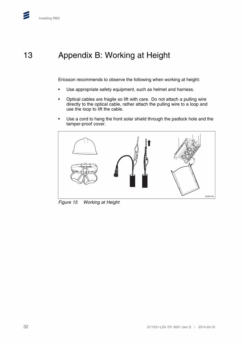
13 Appendix B: Working at Height
Ericsson recommends to observe the following when working at height:
• Use appropriate safety equipment, such as helmet and harness.
• Optical cables are fragile so lift with care. Do not attach a pulling wiredirectly to the optical cable, rather attach the pulling wire to a loop anduse the loop to lift the cable.
• Use a cord to hang the front solar shield through the padlock hole and thetamper-proof cover.
Ge2614A
Figure 15 Working at Height
32 31/1531-LZA 701 6001 Uen D | 2014-03-10
Reference List
Reference List
Safety
[1] Personal Health and Safety Information, 124 46-2885
[2] System Safety Information, 124 46-2886
[3] Transportation and Storage, 114/1551-LZA 701 6001
Site
[4] Installing Optical Cables for Main-Remote Solutions, 15/1531-LZA 7010003
[5] Site Installation Documentation
[6] Installing mUnit Base Mount, 221 06-SXK 107 2861/1
[7] Installing mUnit Pole Clamp, 221 06-SXK 107 2862/1
[8] Installing mUnit Omni Support, 221 06-SXK 107 2863/1
[9] Quick Guide (TX-Monitor for mRBS), 006 92-EN/LZT 751 0148
Generic
[10] RBS Description, RBS 6501, 141/1551-LZA 701 6001
[11] Indicators, Buttons, and Switches, 19/1551-LZA 701 6001
[12] Integrating RBSs On-Site Using ENIS
3331/1531-LZA 701 6001 Uen D | 2014-03-10