rc2 ch01 bigbuck safetyd5 - raw thrills
TRANSCRIPT
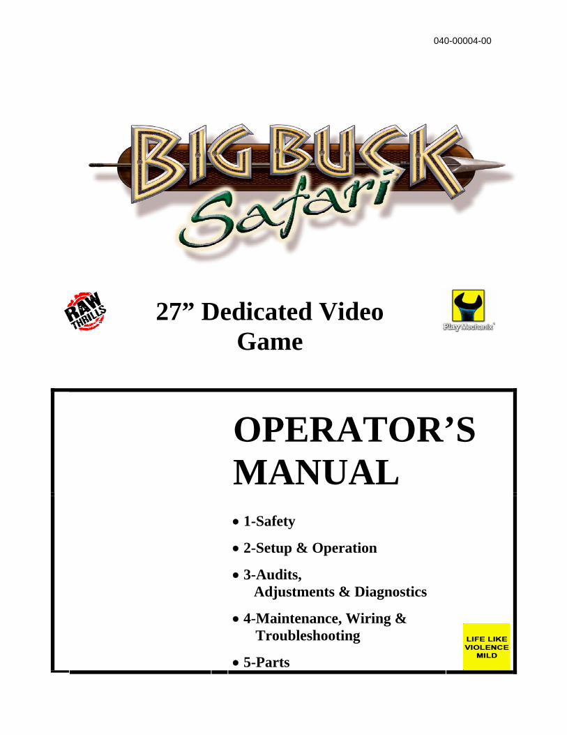
27” Dedicated Video Game
OPERATOR’S MANUAL
• 1-Safety
• 2-Setup & Operation
• 3-Audits, Adjustments & Diagnostics
• 4-Maintenance, Wiring & Troubleshooting
• 5-Parts
040-00004-00

Chapter 1. Setup 1-2
Table of Contents • Chapter 1. Safety ........................................1-5
Warnings, Cautions & Notices .............1-5
• Chapter 2. Setup & Operation ...................2-1 Product Specifications .........................2-1 Inspection & Installation .......................2-1 Gun Calibration Menu ..........................2-3
• Chapter 3. Adjustments, Audits & Diagnostics.........................................3-1 Diagnostic Menu System .....................3-1 Menu Navigation ..................................3-1 Main Menu ...........................................3-2 Menu System Map ...............................3-3 Operator Adjustments Menu................3-4 Game Adjustments Menu ....................3-5 Coin Settings Menu..............................3-6 Player Cost Menu ................................3-7 Volume Menu.......................................3-8 General Audits Menu ...........................3-9 Game Audits Menu ............................3-10 System Audits Menu ..........................3-11 Game Purchase Audits Menu............3-12 Adventure Purchase Audits Menu .....3-13 Bonus Only Audits Menu ...................3-14 Coin Audits Menu...............................3-15 High Scores Menu .............................3-16 Whitetail Adventure Scoreboard ........3-17 Other Scoreboards.............................3-17 Gun Calibration Menu ........................3-18 Reset Menu........................................3-19 System Tests Menu ...........................3-20 Versions Menu ...................................3-21
(Chapter 3. Adjustments, Audits & Diagnostics, continued)
Switch Test Menu ....................... 3-22 Monitor Test Menu...................... 3-23 Color Adjustment Menu .............. 3-24 Screen Adjustment Menu ........... 3-25 Color Screens ............................. 3-25 Sound Tests Menu...................... 3-26 File Test Menu ............................ 3-27 Coin Meter Test .......................... 3-27 DIP Switch Settings Menu .......... 3-27 Start Button Lamps Menu........... 3-27 Watchdog Tests Menu................ 3-27 Adjustments, Audits & Diagnostics Notes .......................................... 3-28
• Chapter 4. Maintenance, Wiring &
Troubleshooting........................... 4-1 Hard Drive Recovery...................... 4-1 BIOS Power Management Setting . 4-2 Monitor Adjustments ...................... 4-3 Cabinet Wiring................................ 4-4 JAMMA I/O Board Connector......... 4-5 Shotgun I/O Board Connector........ 4-5 Troubleshooting Guide................... 4-6 Maintenance, Wiring & Troubleshooting Notes ................... 4-8
• Chapter 5. Parts..................................... 5-1
Shotgun Parts................................ 5-1 Cabinet Parts................................. 5-4

Chapter 1. Setup 1-3
For parts or service, contact your local distributor, or: Betson Enterprises
303 Paterson Plank Road Carlstadt, New Jersey 07072-2307
Main Phone: (201) 438-1300 Toll Free Phone: (800) 524-2343
Part Phone: (800) 828-2048

Chapter 1. Setup 1-4
Safety Notes
Chapter 1. Setup 1-5
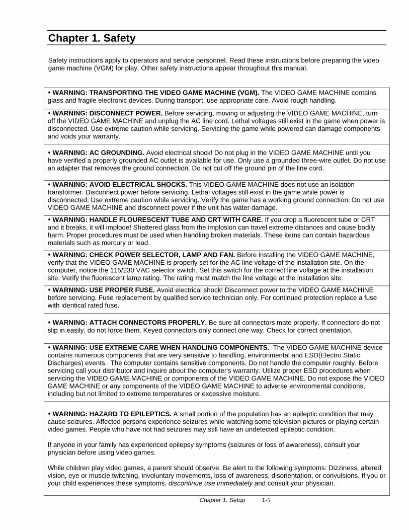
Chapter 1. Safety Safety instructions apply to operators and service personnel. Read these instructions before preparing the video game machine (VGM) for play. Other safety instructions appear throughout this manual.
WARNING: TRANSPORTING THE VIDEO GAME MACHINE (VGM). The VIDEO GAME MACHINE contains glass and fragile electronic devices. During transport, use appropriate care. Avoid rough handling.
WARNING: DISCONNECT POWER. Before servicing, moving or adjusting the VIDEO GAME MACHINE, turn off the VIDEO GAME MACHINE and unplug the AC line cord. Lethal voltages still exist in the game when power is disconnected. Use extreme caution while servicing. Servicing the game while powered can damage components and voids your warranty.
WARNING: AC GROUNDING. Avoid electrical shock! Do not plug in the VIDEO GAME MACHINE until you have verified a properly grounded AC outlet is available for use. Only use a grounded three-wire outlet. Do not use an adapter that removes the ground connection. Do not cut off the ground pin of the line cord.
WARNING: AVOID ELECTRICAL SHOCKS. This VIDEO GAME MACHINE does not use an isolation transformer. Disconnect power before servicing. Lethal voltages still exist in the game while power is disconnected. Use extreme caution while servicing. Verify the game has a working ground connection. Do not use VIDEO GAME MACHINE and disconnect power if the unit has water damage.
WARNING: HANDLE FLOURESCENT TUBE AND CRT WITH CARE. If you drop a fluorescent tube or CRT and it breaks, it will implode! Shattered glass from the implosion can travel extreme distances and cause bodily harm. Proper procedures must be used when handling broken materials. These items can contain hazardous materials such as mercury or lead.
WARNING: CHECK POWER SELECTOR, LAMP AND FAN. Before installing the VIDEO GAME MACHINE, verify that the VIDEO GAME MACHINE is properly set for the AC line voltage of the installation site. On the computer, notice the 115/230 VAC selector switch. Set this switch for the correct line voltage at the installation site. Verify the fluorescent lamp rating. The rating must match the line voltage at the installation site.
WARNING: USE PROPER FUSE. Avoid electrical shock! Disconnect power to the VIDEO GAME MACHINE before servicing. Fuse replacement by qualified service technician only. For continued protection replace a fuse with identical rated fuse.
WARNING: ATTACH CONNECTORS PROPERLY. Be sure all connectors mate properly. If connectors do not slip in easily, do not force them. Keyed connectors only connect one way. Check for correct orientation.
WARNING: USE EXTREME CARE WHEN HANDLING COMPONENTS. The VIDEO GAME MACHINE device contains numerous components that are very sensitive to handling, environmental and ESD(Electro Static Discharges) events. The computer contains sensitive components. Do not handle the computer roughly. Before servicing call your distributor and inquire about the computer's warranty. Utilize proper ESD procedures when servicing the VIDEO GAME MACHINE or components of the VIDEO GAME MACHINE. Do not expose the VIDEO GAME MACHINE or any components of the VIDEO GAME MACHINE to adverse environmental conditions, including but not limited to extreme temperatures or excessive moisture.
WARNING: HAZARD TO EPILEPTICS. A small portion of the population has an epileptic condition that may cause seizures. Affected persons experience seizures while watching some television pictures or playing certain video games. People who have not had seizures may still have an undetected epileptic condition. If anyone in your family has experienced epilepsy symptoms (seizures or loss of awareness), consult your physician before using video games. While children play video games, a parent should observe. Be alert to the following symptoms: Dizziness, altered vision, eye or muscle twitching, involuntary movements, loss of awareness, disorientation, or convulsions. If you or your child experiences these symptoms, discontinue use immediately and consult your physician.
Chapter 1. Setup 1-6
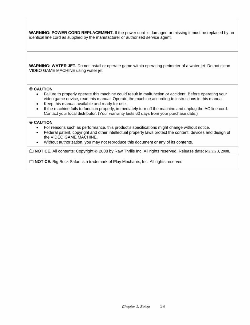
WARNING: POWER CORD REPLACEMENT. If the power cord is damaged or missing it must be replaced by an identical line cord as supplied by the manufacturer or authorized service agent.
WARNING: WATER JET. Do not install or operate game within operating perimeter of a water jet. Do not clean VIDEO GAME MACHINE using water jet.
CAUTION • Failure to properly operate this machine could result in malfunction or accident. Before operating your
video game device, read this manual. Operate the machine according to instructions in this manual. • Keep this manual available and ready for use. • If the machine fails to function properly, immediately turn off the machine and unplug the AC line cord.
Contact your local distributor. (Your warranty lasts 60 days from your purchase date.)
CAUTION • For reasons such as performance, this product’s specifications might change without notice. • Federal patent, copyright and other intellectual property laws protect the content, devices and design of
the VIDEO GAME MACHINE. • Without authorization, you may not reproduce this document or any of its contents.
NOTICE. All contents: Copyright © 2008 by Raw Thrills Inc. All rights reserved. Release date: March 3, 2008.
NOTICE. Big Buck Safari is a trademark of Play Mechanix, Inc. All rights reserved.
Chapter 2. Setup & Operation 2-1
Chapter 2. Setup & Operation
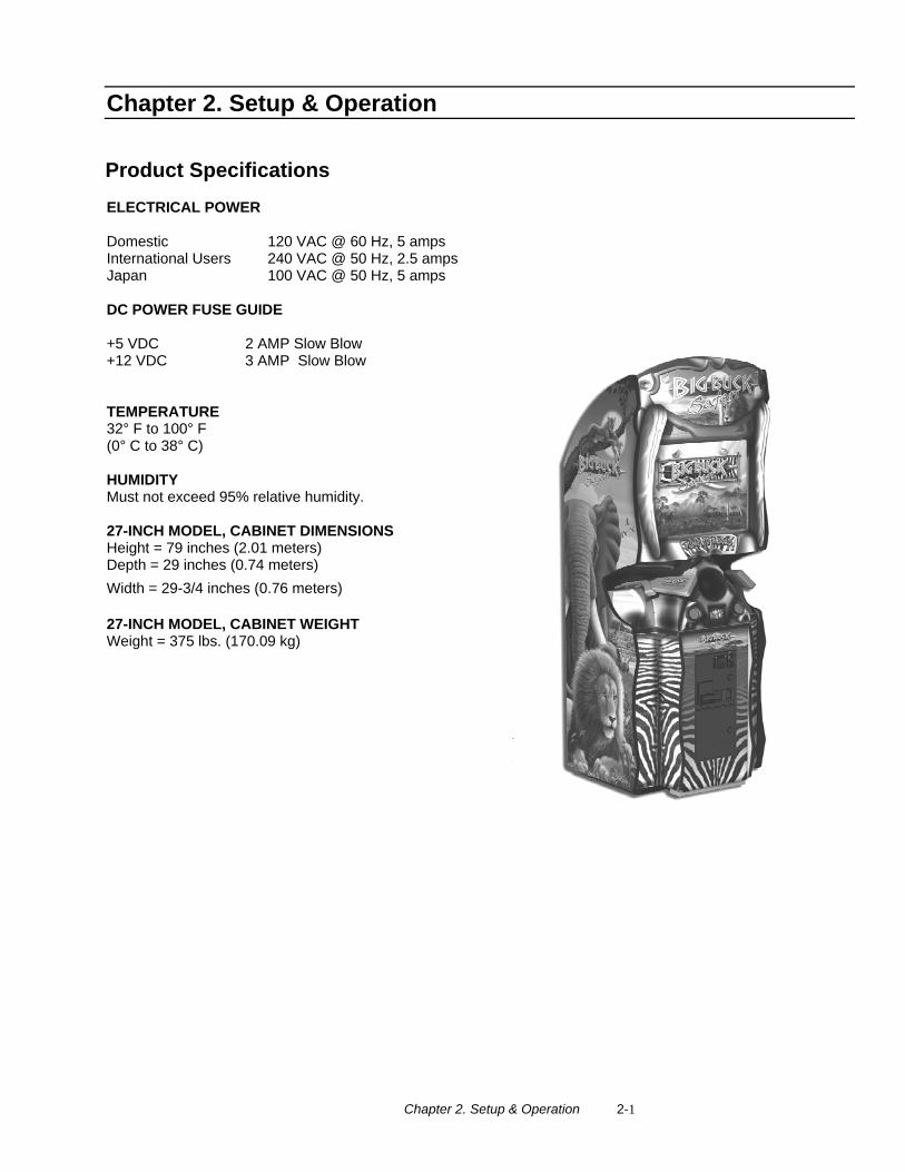
Product Specifications ELECTRICAL POWER Domestic International Users Japan
120 VAC @ 60 Hz, 5 amps 240 VAC @ 50 Hz, 2.5 amps 100 VAC @ 50 Hz, 5 amps
DC POWER FUSE GUIDE +5 VDC 2 AMP Slow Blow +12 VDC 3 AMP Slow Blow TEMPERATURE 32° F to 100° F (0° C to 38° C) HUMIDITY Must not exceed 95% relative humidity. 27-INCH MODEL, CABINET DIMENSIONS Height = 79 inches (2.01 meters) Depth = 29 inches (0.74 meters) Width = 29-3/4 inches (0.76 meters) 27-INCH MODEL, CABINET WEIGHT Weight = 375 lbs. (170.09 kg)
Chapter 2. Setup & Operation 2-2
Inspection & Installation WARNING. Use extreme care when moving or servicing the game cabinet. Moving or servicing the game by
qualified service technicians only. Read this manual before you connect power to the VIDEO GAME MACHINE.
[ ] 1. Make sure the shipping crate is on a flat stable surface.
[ ] 2. Using an appropriate tool, cut the banding straps.
[ ] 3. Remove the cardboard lid from the top of the shipping crate.
[ ] 4. Lift off the large cardboard container that surrounds the VIDEO GAME MACHINE. Do not use a sharp tool to cut the cardboard container the VIDEO GAME MACHINE is enclosed.
[ ] 5. Remove shipping cleats.
[ ] 6. Remove VIDEO GAME MACHINE from the shipping pallet. Seek help as required by your situation.
[ ] 7. Remove packing material from the guns.
[ ] 8. Place the VIDEO GAME MACHINE in a suitable play or service area. [ ] 9. For safety reasons, make sure the game cabinet is level and stable. Adjust the leg levelers as necessary.
Leveling the cabinet is a job for two or more people. Seek help as required by your situation.
[ ] 10. Check the AC line cord for visible signs of damage. Pay particular attention to the plug and line cord insulation.
[ ] 11. Check for shipping damage to the following:
• Gun assembly: Left and right guns, gun holders, and cable
• Cabinet glass: Marquee and monitor
• Cabinet back door
• Cabinet coin door
• Cabinet and gun decals
[ ] 12. Remove the coin door key from the coin return chute.
[ ] 13. Open the top coin door. Locate the key for the back door and the cash box.
[ ] 14. Open the cash box and remove the plastic tub. Remove the items inside the tub. The items enclosed will include this service manual, AC line cord, bag of tools and a warranty card.
[ ] 15. Verify that a proper working AC outlet is available for use. Verify the AC outlet voltage. Verify the AC outlet ground connection is present and working.
[ ] 16. Verify the VIDEO GAME MACHINE is setup for the correct AC voltage. This involves opening the VIDEO GAME MACHINE back door. Use extreme caution when inside the game. Utilize appropriate ESD and safety procedures. Verify that the computer voltage selector switch is properly set to match the AC outlet voltage. Verify the fluorescent fixture in the marquee (top front of the VIDEO GAME MACHINE) is the correct voltage. Verify that the fan is the proper voltage rating. This will involve removing the marquee.
[ ] 17. Once the VIDEO GAME MACHINE voltage has been set/verified and the AC outlet ground and voltage has been verified, plug in the VIDEO GAME MACHINE line cord into the AC outlet.
[ ] 18. On the back of the game cabinet, locate the game AC power switch. The switch is on the bottom left side
(you facing the back side of the VIDEO GAME MACHINE). Turn on the VIDEO GAME MACHINE.
Chapter 2. Setup & Operation 2-3
[ ] 19. Verify that the cooling fan located on the bottom back of the VIDEO GAME MACHINE is working. If not,
turn off and disconnect the AC line cord from the VIDEO GAME MACHINE. Refer to the diagnostic section of this manual for help.
[ ] 20. Verify that the VIDEO GAME MACHINE or any component of the VIDEO GAME MACHINE is not excessively hot or is emitting any foul odors. If so, turn off and disconnect the AC line cord from the VIDEO GAME MACHINE immediately. Refer to the diagnostic section of this manual for help.
[ ] 21. While loading you should see information on the video display. If not, see the diagnostic section of this
manual.
[ ] 22. Once the VIDEO GAME MACHINE software is loaded, it may have the gun calibration screen posted. If not, enter the service menu by pressing the TEST button located on the bracket inside the top coin door.
[ ] 23. Select GUN CALIBRATION.
[ ] 24. Calibrate the guns. See procedure listed next. See the diagnostic section of this manual if errors occur.
[ ] 25. Enter the SWITCH TEST menu. Verify that all the VIDEO GAME MACHINE switches function.
[ ] 26. Enter the SCREEN TEST menu. Verify that the video is acceptable.
[ ] 27. Enter the SOUND TEST menu. Verify the audio works and is not distorted.
[ ] 28. Enter the COIN METER TEST menu. Verify the operation of the coin meter.
[ ] 29. Enter the START BUTTON LAMPS menu. Verify that the lamps of the buttons work correctly.
[ ] 30. Enter the WATCHDOG TEST menu. This test will cause the VIDEO GAME MACHINE to re-boot.
[ ] 31. Upon a successful re-boot of the VIDEO GAME MACHINE, you are ready to adjust your game for operation. Refer to Chapter 3 for this information.
Chapter 2. Setup & Operation 2-4
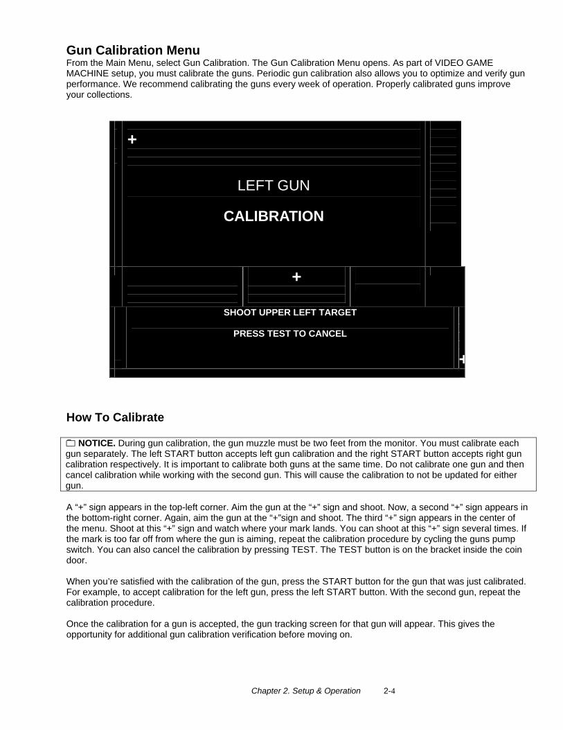
Gun Calibration Menu From the Main Menu, select Gun Calibration. The Gun Calibration Menu opens. As part of VIDEO GAME MACHINE setup, you must calibrate the guns. Periodic gun calibration also allows you to optimize and verify gun performance. We recommend calibrating the guns every week of operation. Properly calibrated guns improve your collections.
+
LEFT GUN
CALIBRATION
+
SHOOT UPPER LEFT TARGET
PRESS TEST TO CANCEL
+
How To Calibrate
NOTICE. During gun calibration, the gun muzzle must be two feet from the monitor. You must calibrate each gun separately. The left START button accepts left gun calibration and the right START button accepts right gun calibration respectively. It is important to calibrate both guns at the same time. Do not calibrate one gun and then cancel calibration while working with the second gun. This will cause the calibration to not be updated for either gun. A “+” sign appears in the top-left corner. Aim the gun at the “+” sign and shoot. Now, a second “+” sign appears in the bottom-right corner. Again, aim the gun at the “+”sign and shoot. The third “+” sign appears in the center of the menu. Shoot at this “+” sign and watch where your mark lands. You can shoot at this “+” sign several times. If the mark is too far off from where the gun is aiming, repeat the calibration procedure by cycling the guns pump switch. You can also cancel the calibration by pressing TEST. The TEST button is on the bracket inside the coin door. When you’re satisfied with the calibration of the gun, press the START button for the gun that was just calibrated. For example, to accept calibration for the left gun, press the left START button. With the second gun, repeat the calibration procedure. Once the calibration for a gun is accepted, the gun tracking screen for that gun will appear. This gives the opportunity for additional gun calibration verification before moving on.
Chapter 2. Setup & Operation 2-5
Setup Notes
Chapter 3. Adjustments, Audits & Diagnostics 3-1
Chapter 3. Adjustments, Audits & Diagnostics
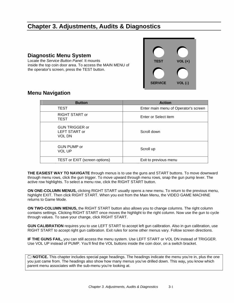
Diagnostic Menu System Locate the Service Button Panel. It mounts inside the top coin door area. To access the MAIN MENU of the operator's screen, press the TEST button.
SERVICE
TEST
VOL (-)
VOL (+)
Menu Navigation
Button Action TEST Enter main menu of Operator's screen
RIGHT START or TEST Enter or Select item
GUN TRIGGER or LEFT START or VOL DN
Scroll down
GUN PUMP or VOL UP Scroll up
TEST or EXIT (screen options) Exit to previous menu THE EASIEST WAY TO NAVIGATE through menus is to use the guns and START buttons. To move downward through menu rows, click the gun trigger. To move upward through menu rows, snap the gun pump lever. The active row highlights. To select a menu row, click the RIGHT START button. ON ONE-COLUMN MENUS, clicking RIGHT START usually opens a new menu. To return to the previous menu, highlight EXIT. Then click RIGHT START. When you exit from the Main Menu, the VIDEO GAME MACHINE returns to Game Mode. ON TWO-COLUMN MENUS, the RIGHT START button also allows you to change columns. The right column contains settings. Clicking RIGHT START once moves the highlight to the right column. Now use the gun to cycle through values. To save your change, click RIGHT START. GUN CALIBRATION requires you to use LEFT START to accept left gun calibration. Also in gun calibration, use RIGHT START to accept right gun calibration. Exit rules for some other menus vary. Follow screen directions. IF THE GUNS FAIL, you can still access the menu system. Use LEFT START or VOL DN instead of TRIGGER. Use VOL UP instead of PUMP. You’ll find the VOL buttons inside the coin door, on a switch bracket.
NOTICE. This chapter includes special page headings. The headings indicate the menu you’re in, plus the one you just came from. The headings also show how many menus you’ve drilled down. This way, you know which parent menu associates with the sub-menu you’re looking at.
Chapter 3. Adjustments, Audits & Diagnostics 3-2
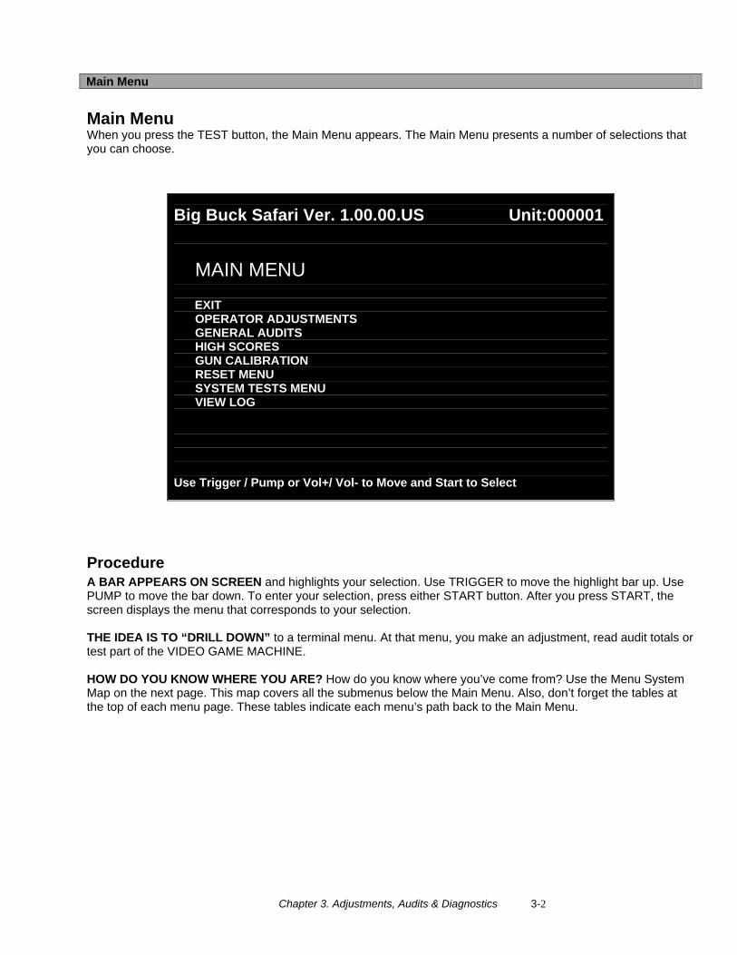
Main Menu Main Menu When you press the TEST button, the Main Menu appears. The Main Menu presents a number of selections that you can choose.
Big Buck Safari Ver. 1.00.00.US Unit:000001
MAIN MENU EXIT OPERATOR ADJUSTMENTS GENERAL AUDITS HIGH SCORES GUN CALIBRATION RESET MENU SYSTEM TESTS MENU VIEW LOG
Use Trigger / Pump or Vol+/ Vol- to Move and Start to Select
Procedure A BAR APPEARS ON SCREEN and highlights your selection. Use TRIGGER to move the highlight bar up. Use PUMP to move the bar down. To enter your selection, press either START button. After you press START, the screen displays the menu that corresponds to your selection. THE IDEA IS TO “DRILL DOWN” to a terminal menu. At that menu, you make an adjustment, read audit totals or test part of the VIDEO GAME MACHINE. HOW DO YOU KNOW WHERE YOU ARE? How do you know where you’ve come from? Use the Menu System Map on the next page. This map covers all the submenus below the Main Menu. Also, don’t forget the tables at the top of each menu page. These tables indicate each menu’s path back to the Main Menu.
Chapter 3. Adjustments, Audits & Diagnostics 3-3
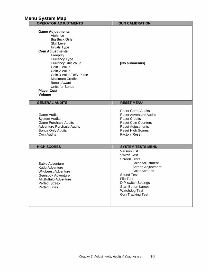
Menu System Map OPERATOR ADJUSTMENTS GUN CALIBRATION
Game Adjustments Violence Big Buck Girls Skill Level Initials Type Coin Adjustments Freeplay Currency Type Currency Unit Value Coin 1 Value Coin 2 Value Coin 3 Value/DBV Pulse Maximum Credits Bonus Award Units for Bonus Player Cost Volume
[No submenus]
GENERAL AUDITS RESET MENU
Game Audits System Audits Game Purchase Audits Adventure Purchase Audits Bonus Only Audits Coin Audits
Reset Game Audits Reset Adventure Audits Reset Credits Reset Coin Counters Reset Adjustments Reset High Scores Factory Reset
HIGH SCORES SYSTEM TESTS MENU
Sable Adventure Kudu Adventure Wildbeest Adventure Gemsbok Adventure Afr.Buffalo Adventure Perfect Streak Perfect Sites
Version List Switch Test Screen Tests Color Adjustment Screen Adjustment Color Screens Sound Test File Test DIP-switch Settings Start Button Lamps Watchdog Test Gun Tracking Test
Chapter 3. Adjustments, Audits & Diagnostics 3-4
Main Menu Operator Adjustments Menu
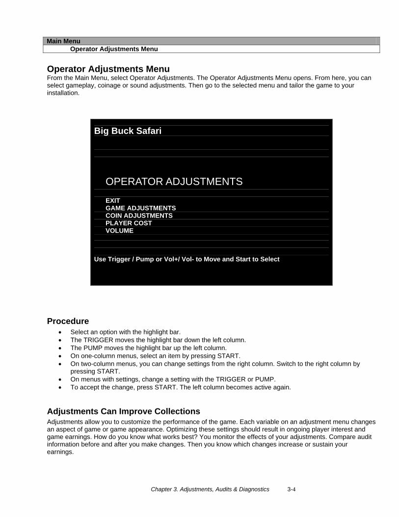
Operator Adjustments Menu From the Main Menu, select Operator Adjustments. The Operator Adjustments Menu opens. From here, you can select gameplay, coinage or sound adjustments. Then go to the selected menu and tailor the game to your installation.
Big Buck Safari
OPERATOR ADJUSTMENTS EXIT GAME ADJUSTMENTS COIN ADJUSTMENTS PLAYER COST VOLUME
Use Trigger / Pump or Vol+/ Vol- to Move and Start to Select
Procedure • Select an option with the highlight bar. • The TRIGGER moves the highlight bar down the left column. • The PUMP moves the highlight bar up the left column. • On one-column menus, select an item by pressing START. • On two-column menus, you can change settings from the right column. Switch to the right column by
pressing START. • On menus with settings, change a setting with the TRIGGER or PUMP. • To accept the change, press START. The left column becomes active again.
Adjustments Can Improve Collections Adjustments allow you to customize the performance of the game. Each variable on an adjustment menu changes an aspect of game or game appearance. Optimizing these settings should result in ongoing player interest and game earnings. How do you know what works best? You monitor the effects of your adjustments. Compare audit information before and after you make changes. Then you know which changes increase or sustain your earnings.
Chapter 3. Adjustments, Audits & Diagnostics 3-5
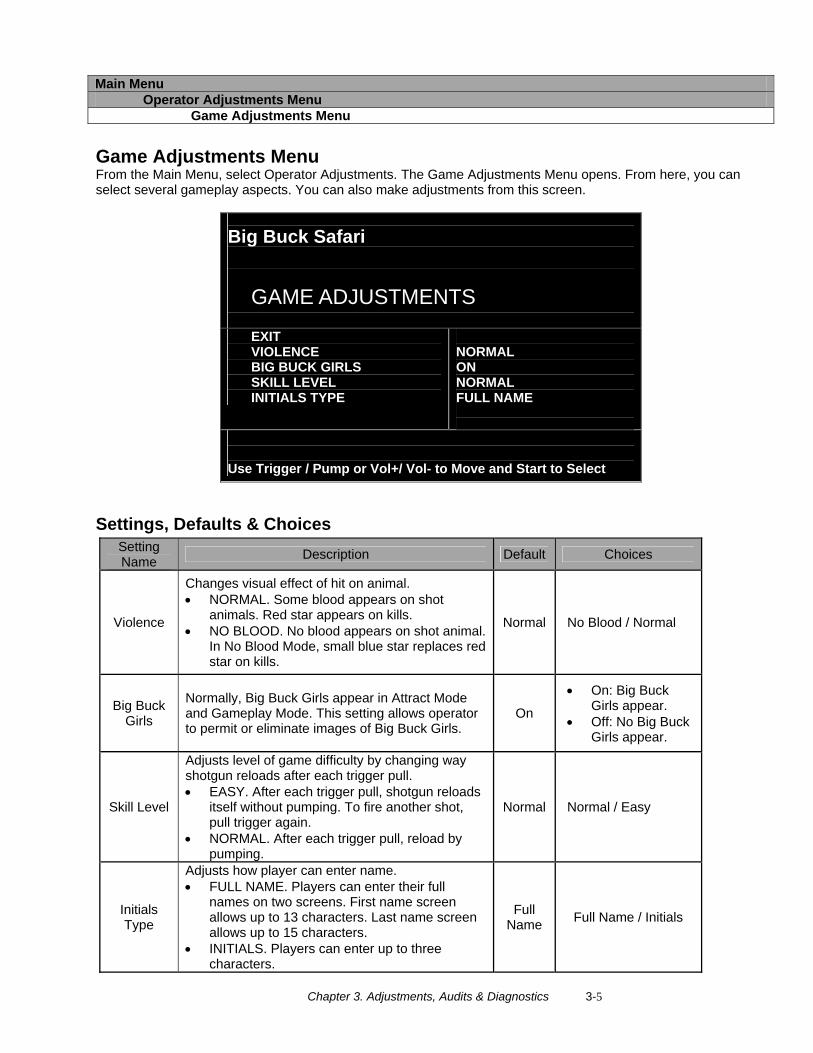
Main Menu Operator Adjustments Menu Game Adjustments Menu
Game Adjustments Menu From the Main Menu, select Operator Adjustments. The Game Adjustments Menu opens. From here, you can select several gameplay aspects. You can also make adjustments from this screen.
Big Buck Safari
GAME ADJUSTMENTS
EXIT VIOLENCE BIG BUCK GIRLS SKILL LEVEL INITIALS TYPE
NORMAL ON NORMAL FULL NAME
Use Trigger / Pump or Vol+/ Vol- to Move and Start to Select
RE
Settings, Defaults & Choices Setting Name Description Default Choices
Violence
Changes visual effect of hit on animal. • NORMAL. Some blood appears on shot
animals. Red star appears on kills. • NO BLOOD. No blood appears on shot animal.
In No Blood Mode, small blue star replaces red star on kills.
Normal No Blood / Normal
Big Buck Girls
Normally, Big Buck Girls appear in Attract Mode and Gameplay Mode. This setting allows operator to permit or eliminate images of Big Buck Girls.
On
• On: Big Buck Girls appear.
• Off: No Big Buck Girls appear.
Skill Level
Adjusts level of game difficulty by changing way shotgun reloads after each trigger pull. • EASY. After each trigger pull, shotgun reloads
itself without pumping. To fire another shot, pull trigger again.
• NORMAL. After each trigger pull, reload by pumping.
Normal Normal / Easy
Initials Type
Adjusts how player can enter name. • FULL NAME. Players can enter their full
names on two screens. First name screen allows up to 13 characters. Last name screen allows up to 15 characters.
• INITIALS. Players can enter up to three characters.
Full Name Full Name / Initials
Chapter 3. Adjustments, Audits & Diagnostics 3-6
Main Menu Operator Adjustments Menu Coin Settings Menu
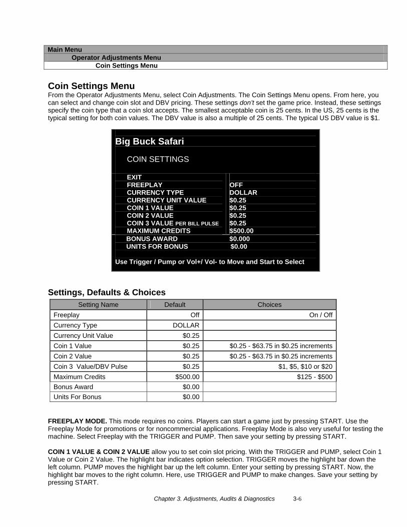
Coin Settings Menu From the Operator Adjustments Menu, select Coin Adjustments. The Coin Settings Menu opens. From here, you can select and change coin slot and DBV pricing. These settings don’t set the game price. Instead, these settings specify the coin type that a coin slot accepts. The smallest acceptable coin is 25 cents. In the US, 25 cents is the typical setting for both coin values. The DBV value is also a multiple of 25 cents. The typical US DBV value is $1.
Big Buck Safari
COIN SETTINGS
EXIT FREEPLAY CURRENCY TYPE CURRENCY UNIT VALUE COIN 1 VALUE COIN 2 VALUE COIN 3 VALUE PER BILL PULSE MAXIMUM CREDITS
OFF DOLLAR $0.25 $0.25 $0.25 $0.25 $500.00
BONUS AWARD $0.000 UNITS FOR BONUS $0.00 Use Trigger / Pump or Vol+/ Vol- to Move and Start to Select
Settings, Defaults & Choices Setting Name Default Choices
Freeplay Off On / OffCurrency Type DOLLARCurrency Unit Value $0.25Coin 1 Value $0.25 $0.25 - $63.75 in $0.25 incrementsCoin 2 Value $0.25 $0.25 - $63.75 in $0.25 incrementsCoin 3 Value/DBV Pulse $0.25 $1, $5, $10 or $20Maximum Credits $500.00 $125 - $500Bonus Award $0.00Units For Bonus $0.00
FREEPLAY MODE. This mode requires no coins. Players can start a game just by pressing START. Use the Freeplay Mode for promotions or for noncommercial applications. Freeplay Mode is also very useful for testing the machine. Select Freeplay with the TRIGGER and PUMP. Then save your setting by pressing START. COIN 1 VALUE & COIN 2 VALUE allow you to set coin slot pricing. With the TRIGGER and PUMP, select Coin 1 Value or Coin 2 Value. The highlight bar indicates option selection. TRIGGER moves the highlight bar down the left column. PUMP moves the highlight bar up the left column. Enter your setting by pressing START. Now, the highlight bar moves to the right column. Here, use TRIGGER and PUMP to make changes. Save your setting by pressing START.

Chapter 3. Adjustments, Audits & Diagnostics 3-7
VALUE PER BILL PULSE allows you to set DBV pricing. The bill validator (DBV) translates bills into electronic pulses. This setting determines one bill’s value in pulses. The number of pulses is always an integer. The smallest acceptable coin value equals one pulse. In a VIDEO GAME MACHINE with US coin mechanisms, one pulse is worth a quarter. Typically, the DBV value is $1.00, or equal to four coins. In that case, the DBV pulses the coin line four times. MAXIMUM CREDITS is the maximum number of unplayed credits that the VIDEO GAME MACHINE allows. BONUS AWARD is the minimum purchase amount needed to earn bonus monetary units. UNIT FOR BONUS AWARD is the monetary unit amount given when BONUS AWARD purchase amount is met.
Chapter 3. Adjustments, Audits & Diagnostics 3-8
Main Menu Operator Adjustments Menu Player Cost Menu
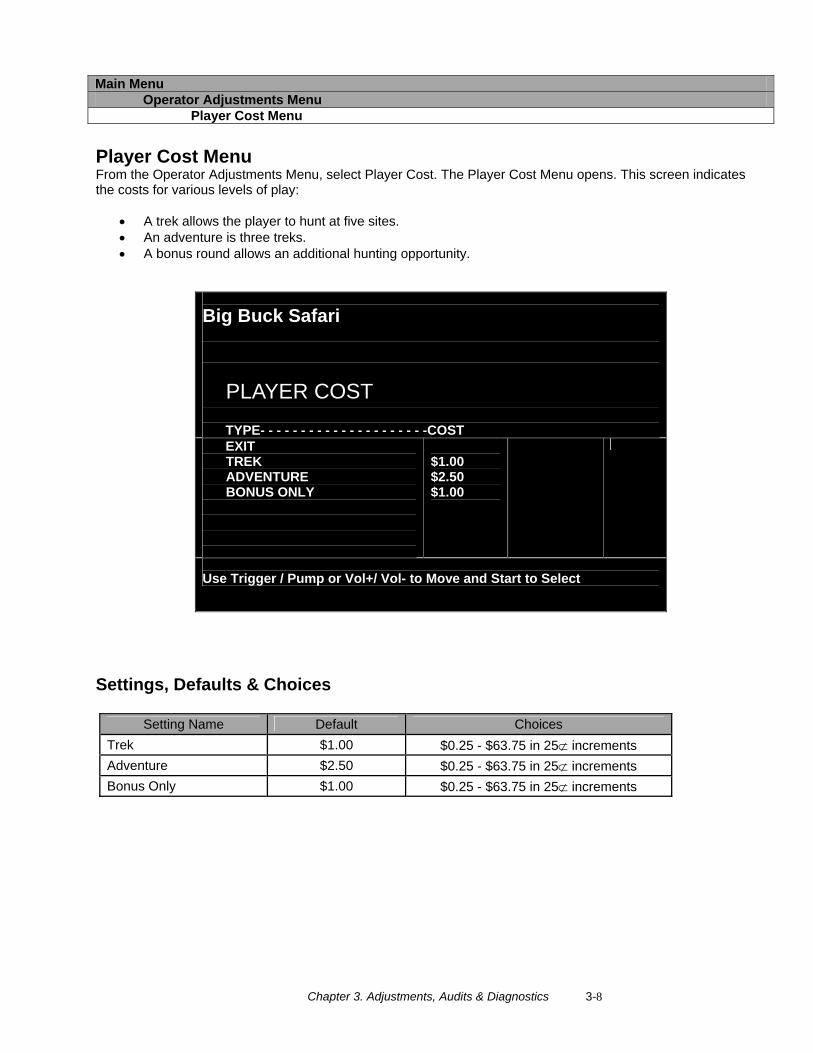
Player Cost Menu From the Operator Adjustments Menu, select Player Cost. The Player Cost Menu opens. This screen indicates the costs for various levels of play:
• A trek allows the player to hunt at five sites. • An adventure is three treks. • A bonus round allows an additional hunting opportunity.
Big Buck Safari
PLAYER COST
TYPE- - - - - - - - - - - - - - - - - - - - -COST EXIT TREK ADVENTURE BONUS ONLY
$1.00 $2.50 $1.00
Use Trigger / Pump or Vol+/ Vol- to Move and Start to Select
Settings, Defaults & Choices
Setting Name Default Choices Trek $1.00 $0.25 - $63.75 in 25⊄ increments Adventure $2.50 $0.25 - $63.75 in 25⊄ increments Bonus Only $1.00 $0.25 - $63.75 in 25⊄ increments
Chapter 3. Adjustments, Audits & Diagnostics 3-9
Main Menu Operator Adjustments Menu Volume Menu
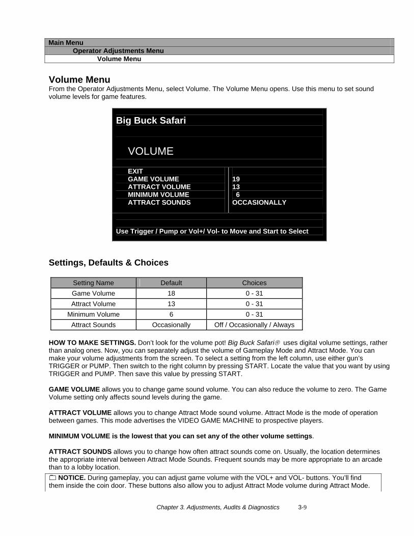
Volume Menu From the Operator Adjustments Menu, select Volume. The Volume Menu opens. Use this menu to set sound volume levels for game features.
Big Buck Safari
VOLUME
EXIT GAME VOLUME ATTRACT VOLUME MINIMUM VOLUME ATTRACT SOUNDS
19 13 6 OCCASIONALLY
Use Trigger / Pump or Vol+/ Vol- to Move and Start to Select
Settings, Defaults & Choices
Setting Name Default Choices Game Volume 18 0 - 31 Attract Volume 13 0 - 31
Minimum Volume 6 0 - 31 Attract Sounds Occasionally Off / Occasionally / Always
HOW TO MAKE SETTINGS. Don’t look for the volume pot! Big Buck Safari® uses digital volume settings, rather than analog ones. Now, you can separately adjust the volume of Gameplay Mode and Attract Mode. You can make your volume adjustments from the screen. To select a setting from the left column, use either gun’s TRIGGER or PUMP. Then switch to the right column by pressing START. Locate the value that you want by using TRIGGER and PUMP. Then save this value by pressing START. GAME VOLUME allows you to change game sound volume. You can also reduce the volume to zero. The Game Volume setting only affects sound levels during the game. ATTRACT VOLUME allows you to change Attract Mode sound volume. Attract Mode is the mode of operation between games. This mode advertises the VIDEO GAME MACHINE to prospective players. MINIMUM VOLUME is the lowest that you can set any of the other volume settings. ATTRACT SOUNDS allows you to change how often attract sounds come on. Usually, the location determines the appropriate interval between Attract Mode Sounds. Frequent sounds may be more appropriate to an arcade than to a lobby location.
NOTICE. During gameplay, you can adjust game volume with the VOL+ and VOL- buttons. You’ll find them inside the coin door. These buttons also allow you to adjust Attract Mode volume during Attract Mode.
Chapter 3. Adjustments, Audits & Diagnostics 3-10
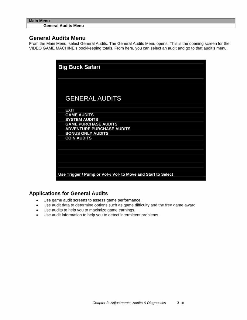
Main Menu General Audits Menu
General Audits Menu From the Main Menu, select General Audits. The General Audits Menu opens. This is the opening screen for the VIDEO GAME MACHINE’s bookkeeping totals. From here, you can select an audit and go to that audit’s menu.
Big Buck Safari
GENERAL AUDITS EXIT GAME AUDITS SYSTEM AUDITS GAME PURCHASE AUDITS ADVENTURE PURCHASE AUDITS BONUS ONLY AUDITS COIN AUDITS
Use Trigger / Pump or Vol+/ Vol- to Move and Start to Select
Applications for General Audits • Use game audit screens to assess game performance. • Use audit data to determine options such as game difficulty and the free game award. • Use audits to help you to maximize game earnings. • Use audit information to help you to detect intermittent problems.
Chapter 3. Adjustments, Audits & Diagnostics 3-11
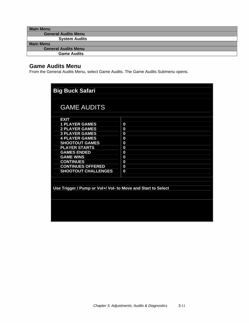
Main Menu General Audits Menu Game Audits
Game Audits Menu From the General Audits Menu, select Game Audits. The Game Audits Submenu opens.
Big Buck Safari
GAME AUDITS
EXIT 1 PLAYER GAMES 2 PLAYER GAMES 3 PLAYER GAMES 4 PLAYER GAMES SHOOTOUT GAMES PLAYER STARTS GAMES ENDED GAME WINS CONTINUES CONTINUES OFFERED SHOOTOUT CHALLENGES
0 0 0 0 0 0 0 0 0 0 0
Use Trigger / Pump or Vol+/ Vol- to Move and Start to Select
Main Menu General Audits Menu System Audits
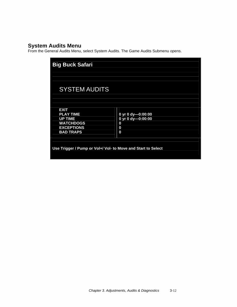
Chapter 3. Adjustments, Audits & Diagnostics 3-12
System Audits Menu From the General Audits Menu, select System Audits. The Game Audits Submenu opens.
Big Buck Safari
SYSTEM AUDITS
EXIT PLAY TIME UP TIME WATCHDOGS EXCEPTIONS BAD TRAPS
0 yr 0 dy—0:00:00 0 yr 0 dy—0:00:00 0 0 0
Use Trigger / Pump or Vol+/ Vol- to Move and Start to Select
Chapter 3. Adjustments, Audits & Diagnostics 3-13
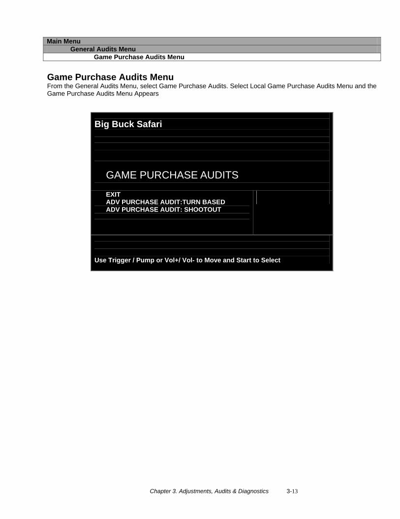
Main Menu General Audits Menu Game Purchase Audits Menu
Game Purchase Audits Menu From the General Audits Menu, select Game Purchase Audits. Select Local Game Purchase Audits Menu and the Game Purchase Audits Menu Appears
Big Buck Safari
GAME PURCHASE AUDITS
EXIT ADV PURCHASE AUDIT:TURN BASED ADV PURCHASE AUDIT: SHOOTOUT
Use Trigger / Pump or Vol+/ Vol- to Move and Start to Select
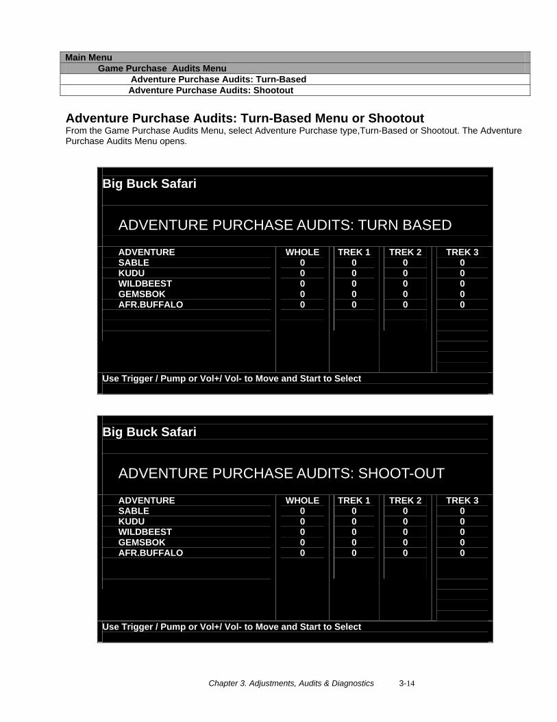
Chapter 3. Adjustments, Audits & Diagnostics 3-14
Main Menu Game Purchase Audits Menu Adventure Purchase Audits: Turn-Based Adventure Purchase Audits: Shootout
Adventure Purchase Audits: Turn-Based Menu or Shootout From the Game Purchase Audits Menu, select Adventure Purchase type,Turn-Based or Shootout. The Adventure Purchase Audits Menu opens.
Big Buck Safari
ADVENTURE PURCHASE AUDITS: TURN BASED
ADVENTURE SABLE KUDU WILDBEEST GEMSBOK AFR.BUFFALO
WHOLE 0 0 0 0 0
TREK 1 0 0 0 0 0
TREK 2 0 0 0 0 0
TREK 3 0 0 0 0 0
Use Trigger / Pump or Vol+/ Vol- to Move and Start to Select
Big Buck Safari
ADVENTURE PURCHASE AUDITS: SHOOT-OUT
ADVENTURE SABLE KUDU WILDBEEST GEMSBOK AFR.BUFFALO
WHOLE 0 0 0 0 0
TREK 1 0 0 0 0 0
TREK 2 0 0 0 0 0
TREK 3 0 0 0 0 0
Use Trigger / Pump or Vol+/ Vol- to Move and Start to Select
Chapter 3. Adjustments, Audits & Diagnostics 3-15
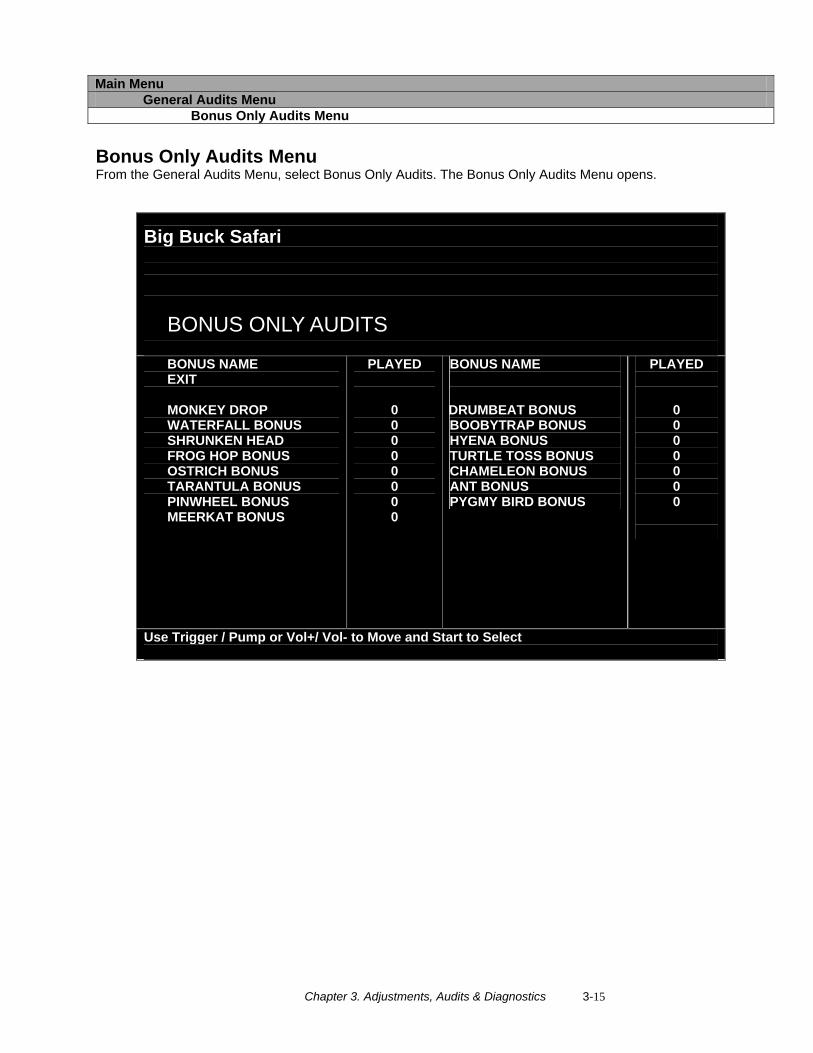
Main Menu General Audits Menu Bonus Only Audits Menu
Bonus Only Audits Menu From the General Audits Menu, select Bonus Only Audits. The Bonus Only Audits Menu opens.
Big Buck Safari
BONUS ONLY AUDITS
BONUS NAME EXIT MONKEY DROP WATERFALL BONUS SHRUNKEN HEAD FROG HOP BONUS OSTRICH BONUS TARANTULA BONUS PINWHEEL BONUS MEERKAT BONUS
PLAYED
0 0 0 0 0 0 0 0
BONUS NAME
DRUMBEAT BONUS BOOBYTRAP BONUS HYENA BONUS TURTLE TOSS BONUS CHAMELEON BONUS ANT BONUS PYGMY BIRD BONUS
PLAYED 0 0 0 0 0 0 0
Use Trigger / Pump or Vol+/ Vol- to Move and Start to Select
Chapter 3. Adjustments, Audits & Diagnostics 3-16
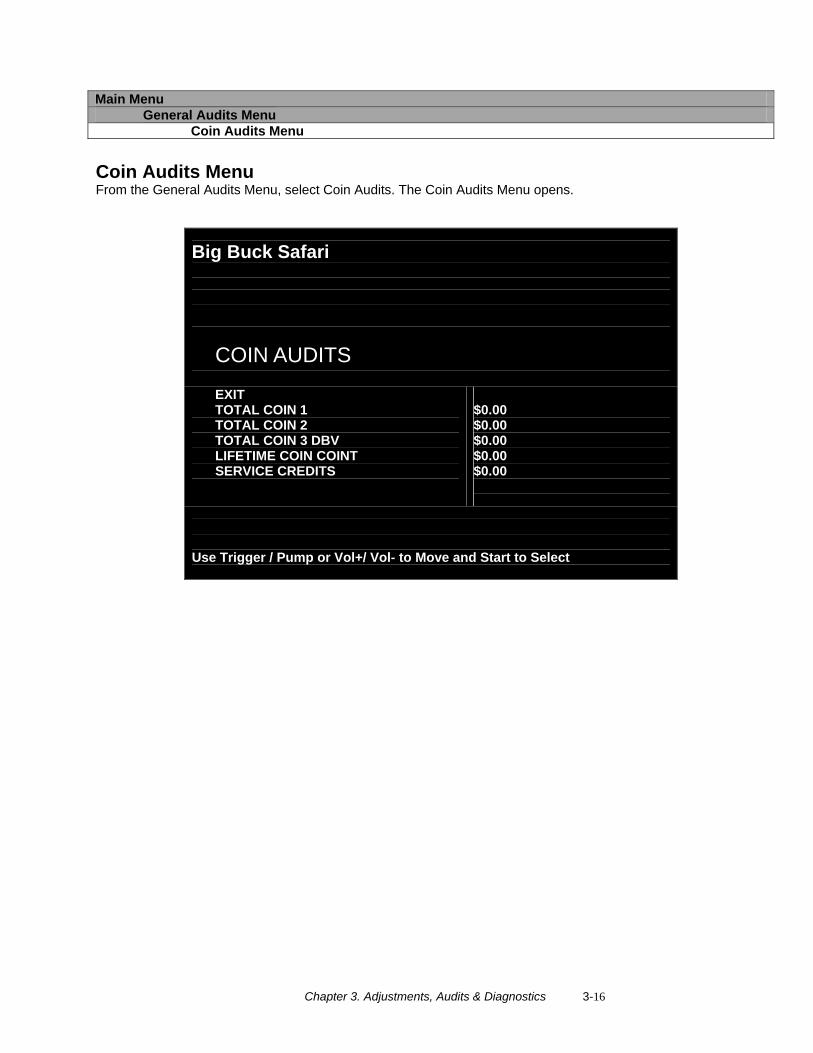
Main Menu General Audits Menu Coin Audits Menu
Coin Audits Menu From the General Audits Menu, select Coin Audits. The Coin Audits Menu opens.
Big Buck Safari
COIN AUDITS
EXIT TOTAL COIN 1 TOTAL COIN 2 TOTAL COIN 3 DBV LIFETIME COIN COINT SERVICE CREDITS
$0.00 $0.00 $0.00 $0.00 $0.00
Use Trigger / Pump or Vol+/ Vol- to Move and Start to Select
Chapter 3. Adjustments, Audits & Diagnostics 3-17
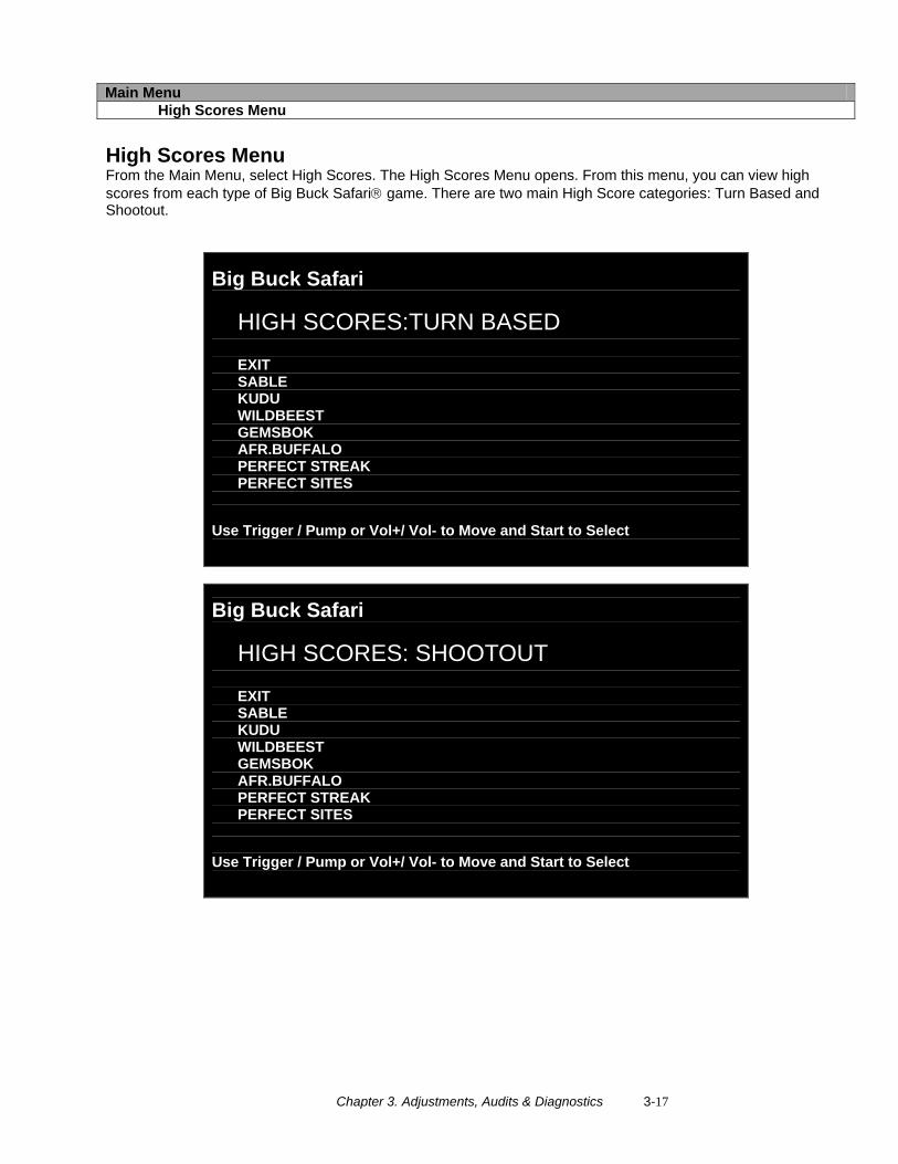
Main Menu High Scores Menu
High Scores Menu From the Main Menu, select High Scores. The High Scores Menu opens. From this menu, you can view high scores from each type of Big Buck Safari® game. There are two main High Score categories: Turn Based and Shootout.
Big Buck Safari
HIGH SCORES:TURN BASED EXIT SABLE KUDU WILDBEEST GEMSBOK AFR.BUFFALO PERFECT STREAK PERFECT SITES
Use Trigger / Pump or Vol+/ Vol- to Move and Start to Select
Big Buck Safari
HIGH SCORES: SHOOTOUT EXIT SABLE KUDU WILDBEEST GEMSBOK AFR.BUFFALO PERFECT STREAK PERFECT SITES
Use Trigger / Pump or Vol+/ Vol- to Move and Start to Select
Chapter 3. Adjustments, Audits & Diagnostics 3-18
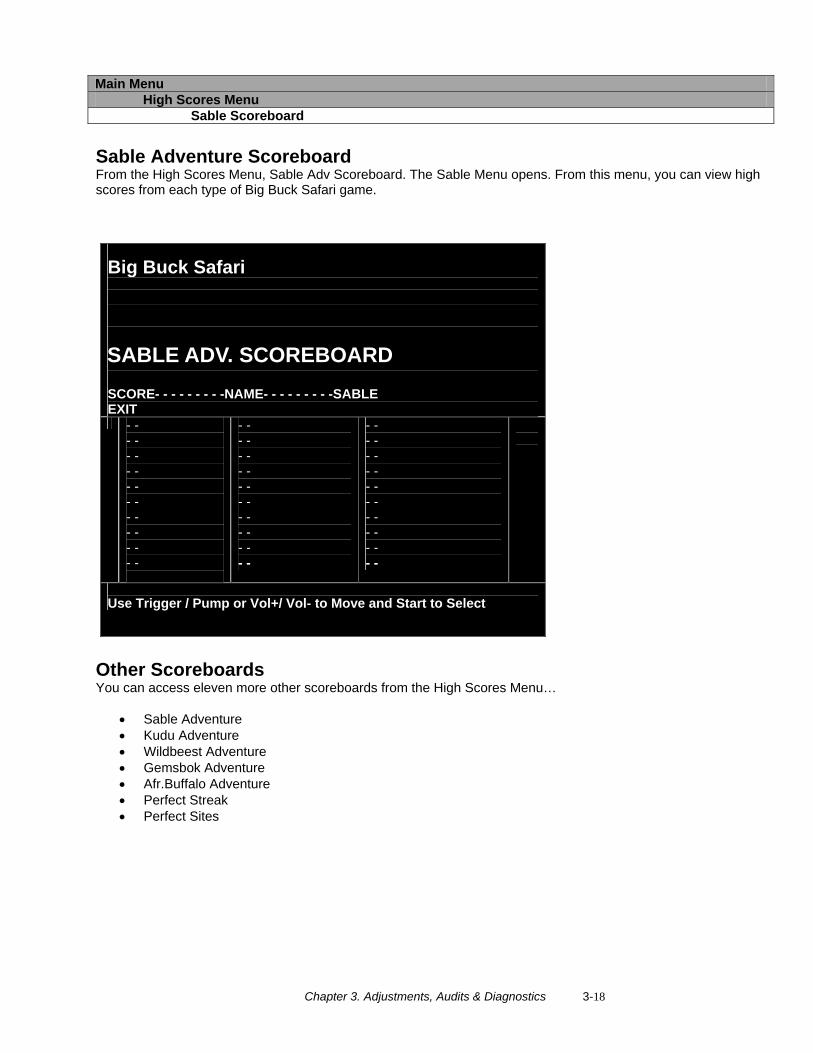
Main Menu High Scores Menu Sable Scoreboard
Sable Adventure Scoreboard From the High Scores Menu, Sable Adv Scoreboard. The Sable Menu opens. From this menu, you can view high scores from each type of Big Buck Safari game.
Big Buck Safari
SABLE ADV. SCOREBOARD SCORE- - - - - - - - -NAME- - - - - - - - -SABLE EXIT - -
- - - - - - - - - - - - - - - - - -
- - - - - - - - - - - - - - - - - - - -
- - - - - - - - - - - - - - - - - - - -
Use Trigger / Pump or Vol+/ Vol- to Move and Start to Select
Other Scoreboards You can access eleven more other scoreboards from the High Scores Menu…
• Sable Adventure • Kudu Adventure • Wildbeest Adventure • Gemsbok Adventure • Afr.Buffalo Adventure • Perfect Streak • Perfect Sites
Chapter 3. Adjustments, Audits & Diagnostics 3-19
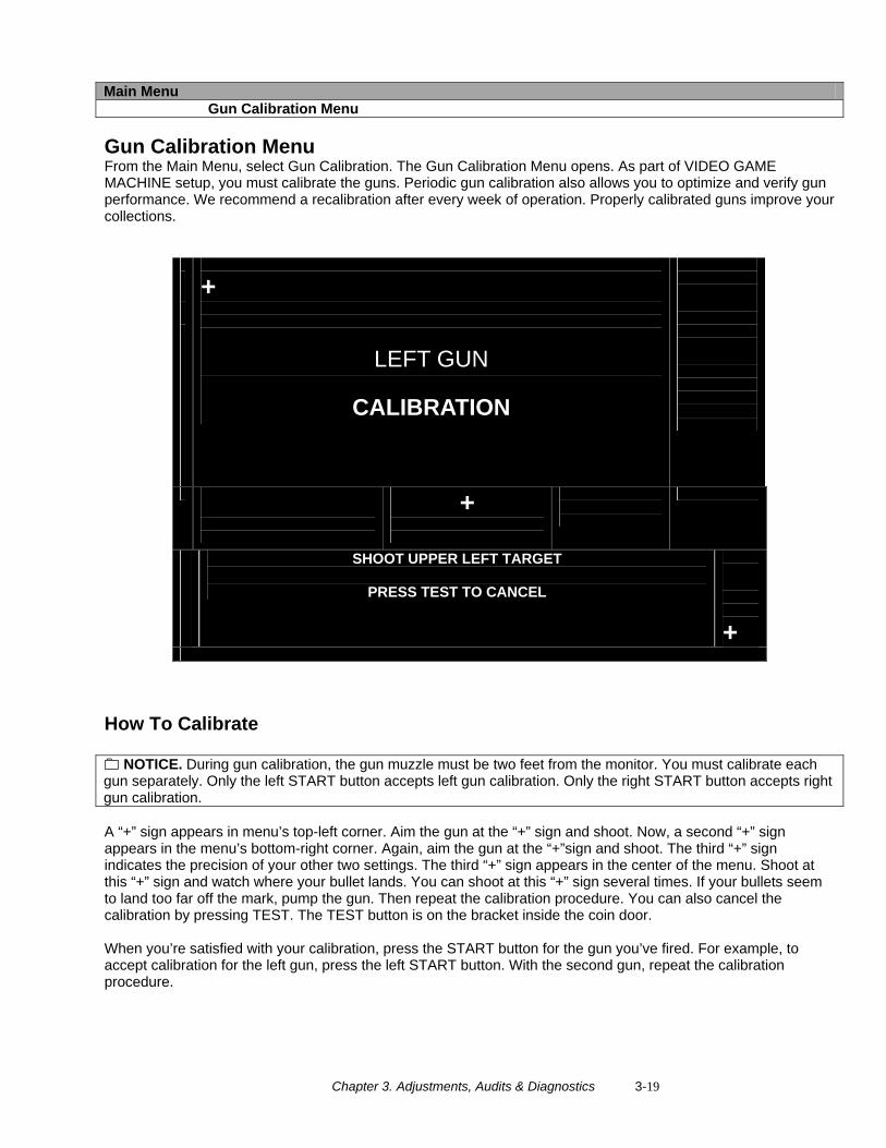
Main Menu Gun Calibration Menu Gun Calibration Menu From the Main Menu, select Gun Calibration. The Gun Calibration Menu opens. As part of VIDEO GAME MACHINE setup, you must calibrate the guns. Periodic gun calibration also allows you to optimize and verify gun performance. We recommend a recalibration after every week of operation. Properly calibrated guns improve your collections.
+
LEFT GUN
CALIBRATION
+
SHOOT UPPER LEFT TARGET
PRESS TEST TO CANCEL
+
How To Calibrate
NOTICE. During gun calibration, the gun muzzle must be two feet from the monitor. You must calibrate each gun separately. Only the left START button accepts left gun calibration. Only the right START button accepts right gun calibration. A “+” sign appears in menu’s top-left corner. Aim the gun at the “+” sign and shoot. Now, a second “+” sign appears in the menu’s bottom-right corner. Again, aim the gun at the “+”sign and shoot. The third “+” sign indicates the precision of your other two settings. The third “+” sign appears in the center of the menu. Shoot at this “+” sign and watch where your bullet lands. You can shoot at this “+” sign several times. If your bullets seem to land too far off the mark, pump the gun. Then repeat the calibration procedure. You can also cancel the calibration by pressing TEST. The TEST button is on the bracket inside the coin door. When you’re satisfied with your calibration, press the START button for the gun you’ve fired. For example, to accept calibration for the left gun, press the left START button. With the second gun, repeat the calibration procedure.
Chapter 3. Adjustments, Audits & Diagnostics 3-20
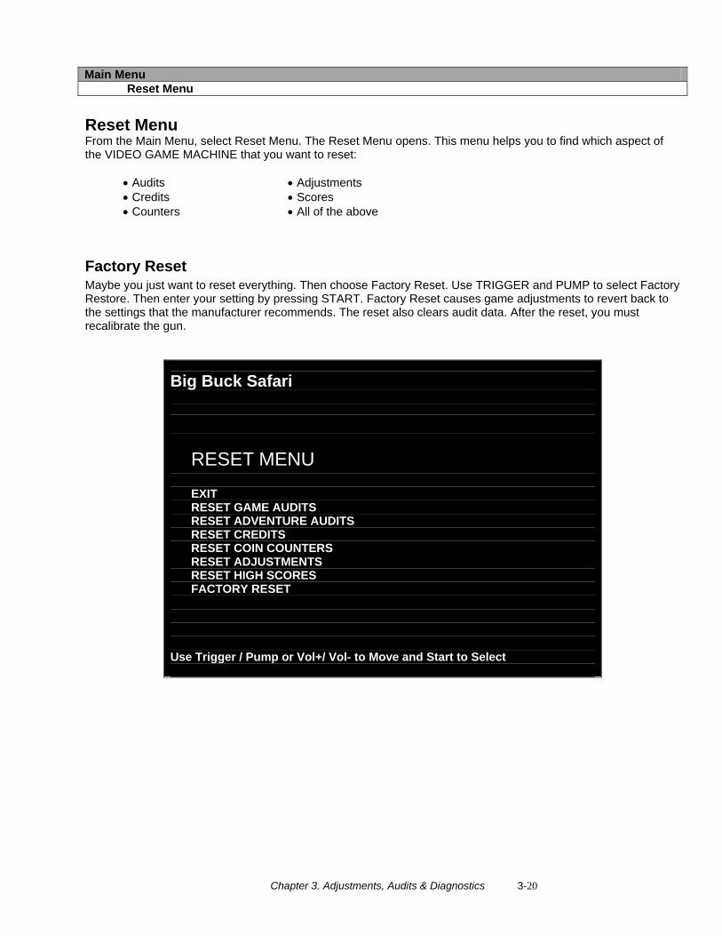
Main Menu Reset Menu
Reset Menu From the Main Menu, select Reset Menu. The Reset Menu opens. This menu helps you to find which aspect of the VIDEO GAME MACHINE that you want to reset: • Audits
• Credits • Counters
• Adjustments • Scores • All of the above
Factory Reset Maybe you just want to reset everything. Then choose Factory Reset. Use TRIGGER and PUMP to select Factory Restore. Then enter your setting by pressing START. Factory Reset causes game adjustments to revert back to the settings that the manufacturer recommends. The reset also clears audit data. After the reset, you must recalibrate the gun.
Big Buck Safari
RESET MENU EXIT RESET GAME AUDITS RESET ADVENTURE AUDITS RESET CREDITS RESET COIN COUNTERS RESET ADJUSTMENTS RESET HIGH SCORES FACTORY RESET
Use Trigger / Pump or Vol+/ Vol- to Move and Start to Select
Chapter 3. Adjustments, Audits & Diagnostics 3-21
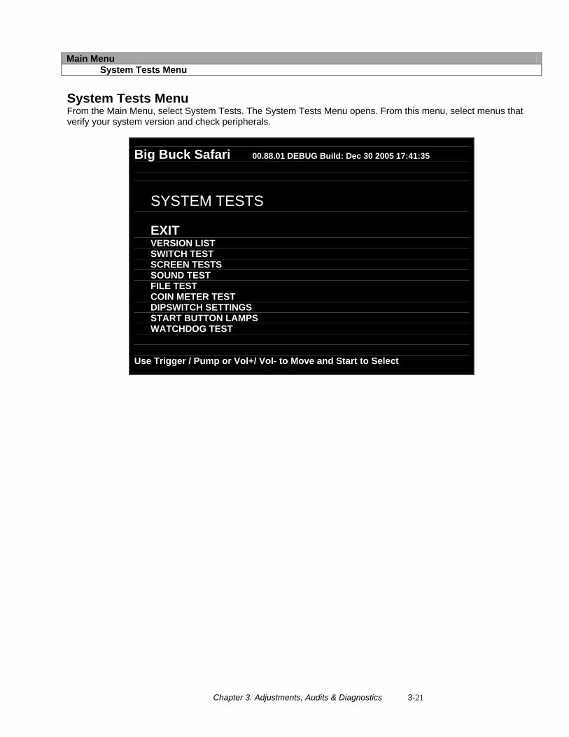
Main Menu System Tests Menu
System Tests Menu From the Main Menu, select System Tests. The System Tests Menu opens. From this menu, select menus that verify your system version and check peripherals.
Big Buck Safari 00.88.01 DEBUG Build: Dec 30 2005 17:41:35
SYSTEM TESTS EXIT VERSION LIST SWITCH TEST SCREEN TESTS SOUND TEST FILE TEST COIN METER TEST DIPSWITCH SETTINGS START BUTTON LAMPS WATCHDOG TEST
Use Trigger / Pump or Vol+/ Vol- to Move and Start to Select
Chapter 3. Adjustments, Audits & Diagnostics 3-22
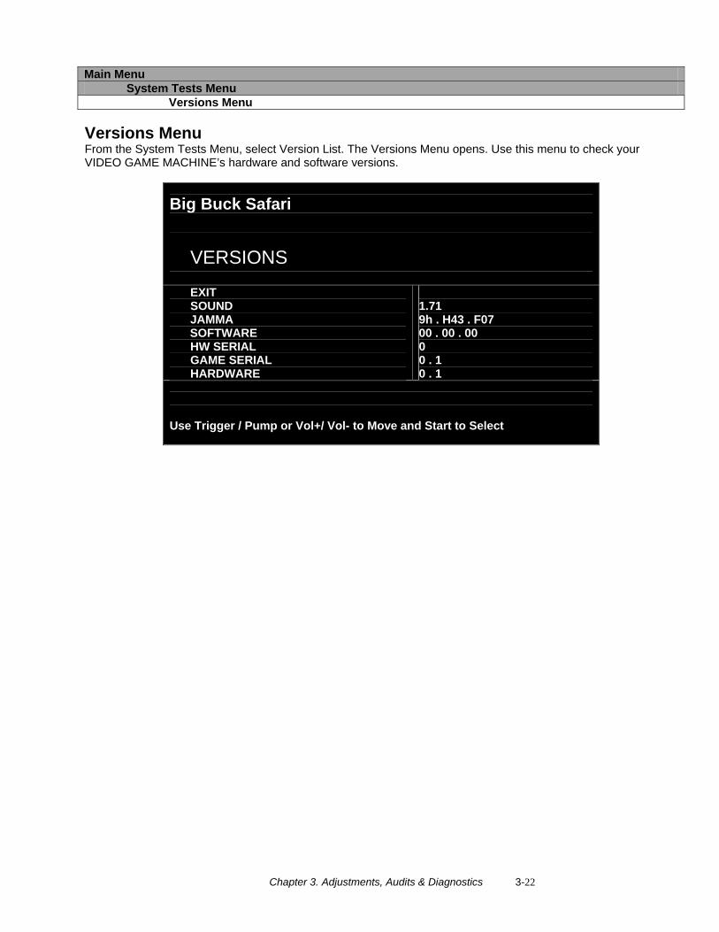
Main Menu System Tests Menu Versions Menu Versions Menu From the System Tests Menu, select Version List. The Versions Menu opens. Use this menu to check your VIDEO GAME MACHINE’s hardware and software versions.
Big Buck Safari
VERSIONS
EXIT SOUND JAMMA SOFTWARE HW SERIAL GAME SERIAL HARDWARE
1.71 9h . H43 . F07 00 . 00 . 00 0 0 . 1 0 . 1
Use Trigger / Pump or Vol+/ Vol- to Move and Start to Select
Chapter 3. Adjustments, Audits & Diagnostics 3-23
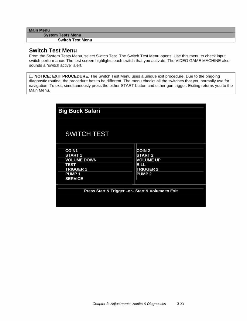
Main Menu System Tests Menu Switch Test Menu Switch Test Menu From the System Tests Menu, select Switch Test. The Switch Test Menu opens. Use this menu to check input switch performance. The test screen highlights each switch that you activate. The VIDEO GAME MACHINE also sounds a “switch active” alert.
NOTICE: EXIT PROCEDURE. The Switch Test Menu uses a unique exit procedure. Due to the ongoing diagnostic routine, the procedure has to be different. The menu checks all the switches that you normally use for navigation. To exit, simultaneously press the either START button and either gun trigger. Exiting returns you to the Main Menu.
Big Buck Safari
SWITCH TEST
COIN1 START 1 VOLUME DOWN TEST TRIGGER 1 PUMP 1 SERVICE
COIN 2 START 2 VOLUME UP BILL TRIGGER 2 PUMP 2
Press Start & Trigger –or– Start & Volume to Exit
Chapter 3. Adjustments, Audits & Diagnostics 3-24
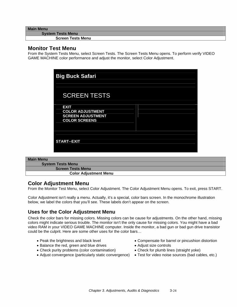
Main Menu System Tests Menu Screen Tests Menu Monitor Test Menu From the System Tests Menu, select Screen Tests. The Screen Tests Menu opens. To perform verify VIDEO GAME MACHINE color performance and adjust the monitor, select Color Adjustment.
Big Buck Safari
SCREEN TESTS
EXIT COLOR ADJUSTMENT SCREEN ADJUSTMENT COLOR SCREENS
START--EXIT
Main Menu System Tests Menu Screen Tests Menu Color Adjustment Menu Color Adjustment Menu From the Monitor Test Menu, select Color Adjustment. The Color Adjustment Menu opens. To exit, press START. Color Adjustment isn’t really a menu. Actually, it’s a special, color bars screen. In the monochrome illustration below, we label the colors that you’ll see. These labels don’t appear on the screen.
Uses for the Color Adjustment Menu Check the color bars for missing colors. Missing colors can be cause for adjustments. On the other hand, missing colors might indicate serious trouble. The monitor isn’t the only cause for missing colors. You might have a bad video RAM in your VIDEO GAME MACHINE computer. Inside the monitor, a bad gun or bad gun drive transistor could be the culprit. Here are some other uses for the color bars…
• Peak the brightness and black level • Balance the red, green and blue drives • Check purity problems (color contamination) • Adjust convergence (particularly static convergence)
• Compensate for barrel or pincushion distortion • Adjust size controls • Check for plumb lines (straight yoke) • Test for video noise sources (bad cables, etc.)

Chapter 3. Adjustments, Audits & Diagnostics 3-25
Gray
Yellow
Cyan
Green
Magenta
Red
Blue
PRESS START TO EXIT
Chapter 3. Adjustments, Audits & Diagnostics 3-26
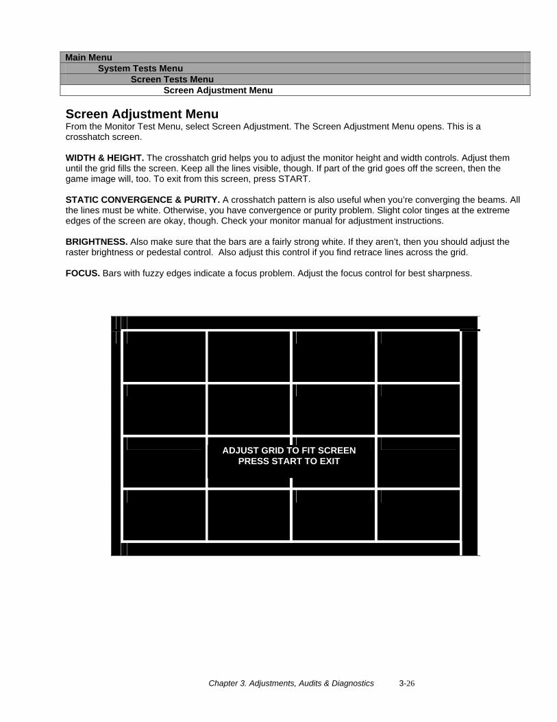
Main Menu System Tests Menu Screen Tests Menu Screen Adjustment Menu Screen Adjustment Menu From the Monitor Test Menu, select Screen Adjustment. The Screen Adjustment Menu opens. This is a crosshatch screen. WIDTH & HEIGHT. The crosshatch grid helps you to adjust the monitor height and width controls. Adjust them until the grid fills the screen. Keep all the lines visible, though. If part of the grid goes off the screen, then the game image will, too. To exit from this screen, press START. STATIC CONVERGENCE & PURITY. A crosshatch pattern is also useful when you’re converging the beams. All the lines must be white. Otherwise, you have convergence or purity problem. Slight color tinges at the extreme edges of the screen are okay, though. Check your monitor manual for adjustment instructions. BRIGHTNESS. Also make sure that the bars are a fairly strong white. If they aren’t, then you should adjust the raster brightness or pedestal control. Also adjust this control if you find retrace lines across the grid. FOCUS. Bars with fuzzy edges indicate a focus problem. Adjust the focus control for best sharpness.
ADJUST GRID TO FIT SCREEN PRESS START TO EXIT
Chapter 3. Adjustments, Audits & Diagnostics 3-27
Main Menu System Tests Menu Screen Tests Menu Color Screens Color Screens From the Monitor Test Menu, select Color Screens. Color screens are solid, one-color images. You can cycle through screens with the START button. Pressing start once more cause you to exit. You’ll find five screens…
• Black • Green • White • Blue • Red
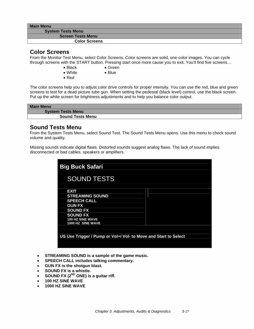
The color screens help you to adjust color drive controls for proper intensity. You can use the red, blue and green screens to test for a dead picture tube gun. When setting the pedestal (black level) control, use the black screen. Put up the white screen for brightness adjustments and to help you balance color output. Main Menu System Tests Menu Sound Tests Menu Sound Tests Menu From the System Tests Menu, select Sound Test. The Sound Tests Menu opens. Use this menu to check sound volume and quality. Missing sounds indicate digital flaws. Distorted sounds suggest analog flaws. The lack of sound implies disconnected or bad cables, speakers or amplifiers.
Big Buck Safari
SOUND TESTS
EXIT STREAMING SOUND SPEECH CALL GUN FX SOUND FX SOUND FX 100 HZ SINE WAVE 1000 HZ SINE WAVE
US Use Trigger / Pump or Vol+/ Vol- to Move and Start to Select
• STREAMING SOUND is a sample of the game music. • SPEECH CALL includes talking commentary. • GUN FX is the shotgun blast. • SOUND FX is a whistle. • SOUND FX (2ND ONE) is a guitar riff. • 100 HZ SINE WAVE • 1000 HZ SINE WAVE
Chapter 3. Adjustments, Audits & Diagnostics 3-28
Main Menu System Tests Menu File Test Menu File Test Menu From the System Tests Menu, select File Test. The File Test Menu opens. This menu runs a checksum test of system memory. Afterward, an onscreen message informs you of file status. If the memory is good, you can proceed with the next test. Otherwise, proceed to Chapter 4, Maintenance, Wiring & Troubleshooting. Run a hard drive recovery.
CAUTION If your VIDEO GAME MACHINE fails the file test, don’t proceed with system tests. Corrupt files as indicated by the message “ Errors Detected in Files...” affect gameplay and the results of the other tests. If file errors result from failing power circuits, continued operation might cause further damage. Main Menu System Tests Menu Coin Meter Test Coin Meter Test From the System Tests Menu, select Coin Meter Test. No menu opens. For this test, the System Tests Menu is the bottom-level menu. Watch your VIDEO GAME MACHINE’s mechanical coin meter. You’ll find this meter on the switch bracket behind the coin door. When you select Coin Meter Test, the meter should increment by one count. If it does, then the meter is okay. If the meter doesn’t click, then it probably isn’t receiving a pulse from the VIDEO GAME MACHINE. Troubleshoot the problem. If the meter clicks, but doesn’t increment, replace the meter. Main Menu System Tests Menu DIP Switch Settings Menu DIP Switch Settings Menu From the System Tests Menu, select DIP Switch Settings. The DIP Switch Settings Menu opens. Use this menu to check settings of the I/O Board DIP switches. For normal operation, all eight switches must be off. Main Menu System Tests Menu Start Button Lamps Menu Start Button Lamps Menu From the System Tests Menu, select Start Button Lamps. The Start Button Lamps Menu opens. Use this menu to check for burned out START button LEDs. The test blinks the LEDs. Replace failed parts. Main Menu System Tests Menu Watchdog Test Menu Watchdog Tests Menu From the System Tests Menu, select Watchdog Test. The Watchdog Test Menu opens. Use this menu to test the Watchdog circuit. This circuit protects the VIDEO GAME MACHINE against screen freezes (loops). After a countdown, the Watchdog Test resets the VIDEO GAME MACHINE. To exit before the reset, use PUMP, TRIGGER, START or either VOLUME button. If the test succeeds, the game resets normally. If the test fails, the reset process loops or ends abnormally. If you encounter a failure mode, troubleshoot the VIDEO GAME MACHINE or call for service.
Chapter 3. Adjustments, Audits & Diagnostics 3-29
Adjustments, Audits & Diagnostics Notes
March 3, 2008
Chapter 4. Maintenance, Wiring & Troubleshooting 4-1
Chapter 4. Maintenance, Wiring & Troubleshooting
Hard Drive Recovery
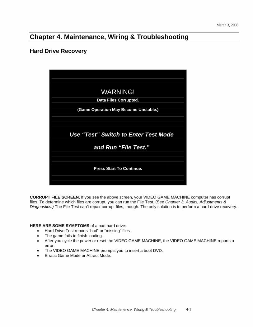
WARNING! Data Files Corrupted.
(Game Operation May Become Unstable.)
Use “Test” Switch to Enter Test Mode
and Run “File Test.”
Press Start To Continue.
CORRUPT FILE SCREEN. If you see the above screen, your VIDEO GAME MACHINE computer has corrupt files. To determine which files are corrupt, you can run the File Test. (See Chapter 3, Audits, Adjustments & Diagnostics.) The File Test can’t repair corrupt files, though. The only solution is to perform a hard-drive recovery. HERE ARE SOME SYMPTOMS of a bad hard drive:
• Hard Drive Test reports “bad” or “missing” files. • The game fails to finish loading. • After you cycle the power or reset the VIDEO GAME MACHINE, the VIDEO GAME MACHINE reports a
error. • The VIDEO GAME MACHINE prompts you to insert a boot DVD. • Erratic Game Mode or Attract Mode.
March 3, 2008
Chapter 4. Maintenance, Wiring & Troubleshooting 4-2
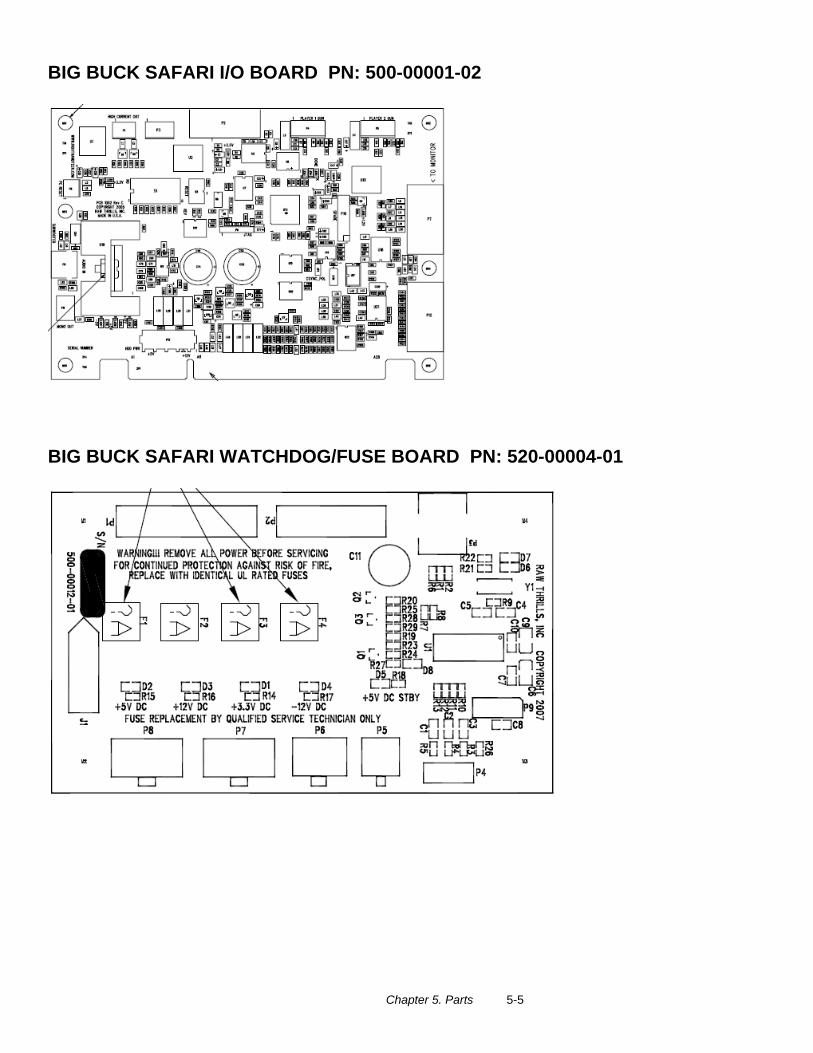
From the back of the VIDEO GAME MACHINE, check the I/O board. The I/O board must have powered and be connected to the computer. A serial cable connects the computer and the I/O board.
1. Verify that the I/O Board has power. 2. 3. To access the computer, open the coin door. 4. Open the DVD tray by pressing the button on the DVD drive. 5. Insert the recovery disk into the tray. 6. Close the DVD tray by pressing the button on the DVD drive. 7. Turn-off the VIDEO GAME MACHINE via the main AC switch.. 8. Turn-on the VIDEO GAME MACHINE via the main AC switch. The disk recovery process begins
automatically. Recovery may take 30 to 40 minutes. 9. Look for a message at the bottom of the screen. When the recovery is over, the message prompts you to
remove your disk. Open the DVD tray by pressing the DVD drive button. Remove the recovery disk. Store it safely.
10. 11. Turn-off the VIDEO GAME MACHINE via the main AC switch. 12. Turn-on the VIDEO GAME MACHINE via the main AC switch.
CAUTION. During the following process, don’t interrupt power or reset the game!
13. The VIDEO GAME MACHINE will do a first-boot initialization procedure. This will take a few minutes. The
VIDEO GAME MACHINE will require that the optical guns be calibrated. The VIDEO GAME MACHINE will automatically enter the gun calibration mode.
BIOS Settings / Power Management
NOTICE. Big Buck Safari® ships with the correct BIOS settings. Making BIOS changes will adversely affect the VIDEO GAME MACHINE.
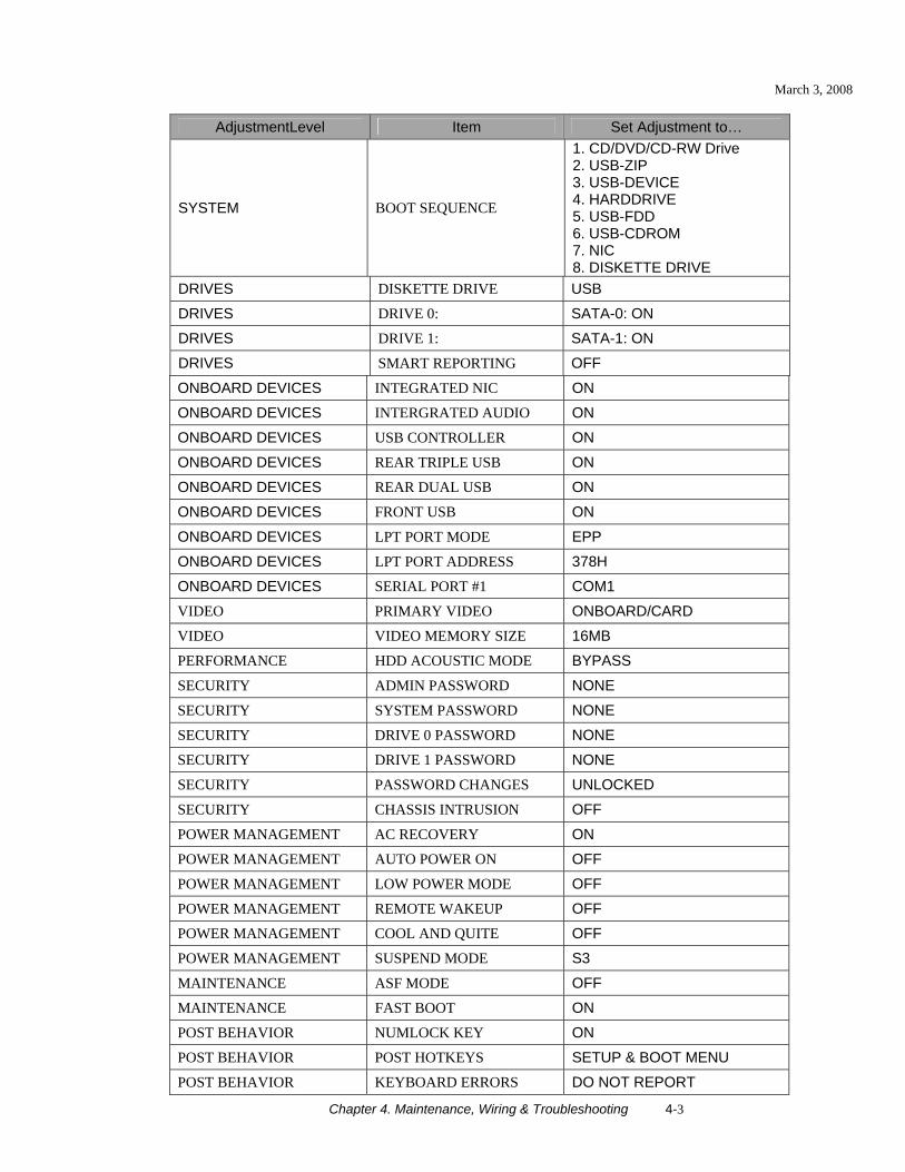
The BIOS settings along with the functionality of the FUSE/WD board (p/n 500-00012-01) allows the main VIDEO GAME MACHINE to power correctly. The BIOS settings need to match the settings listed below. Otherwise the VIDEO GAME MACHINE will not properly recover from being turned-off, power failure, or brownout. It is also noteworthy that the FUSE/WD board makes the functionality of the power switch on the computer not function as one would expect. Never use the power switch on the computer. Proper power control for the VIDEO GAME MACHINE is performed by using the main AC power switch located on the lower backside of the VIDEO GAME MACHINE. BIOS Procedure
1. Turn the game off. 2. Connect a USB keyboard to the computer.
3. While holding the [F2] key, turn on the main power switch of the VIDEO GAME MACHINE. The BIOS
menu screen will appear. For a Dell Computer, verify the settings listed in the following table on the next page.
4. To save and exit, follow the instructions on the BIOS screen. The computer will reset and load the game.
NOTICE. Big Buck Safari® ships with a recovery DVD. Hard drives occasionally fail. If your disk fails, restore hard drive data by following this procedure. Avoid rough handling of the computer or DVD. Check the Troubleshooting Guide in this document.
March 3, 2008
Chapter 4. Maintenance, Wiring & Troubleshooting 4-3
AdjustmentLevel Item Set Adjustment to…
SYSTEM BOOT SEQUENCE
1. CD/DVD/CD-RW Drive 2. USB-ZIP 3. USB-DEVICE 4. HARDDRIVE 5. USB-FDD 6. USB-CDROM 7. NIC 8. DISKETTE DRIVE
DRIVES DISKETTE DRIVE USB
DRIVES DRIVE 0: SATA-0: ON
DRIVES DRIVE 1: SATA-1: ON
DRIVES SMART REPORTING OFF
ONBOARD DEVICES INTEGRATED NIC ON
ONBOARD DEVICES INTERGRATED AUDIO ON
ONBOARD DEVICES USB CONTROLLER ON
ONBOARD DEVICES REAR TRIPLE USB ON
ONBOARD DEVICES REAR DUAL USB ON
ONBOARD DEVICES FRONT USB ON
ONBOARD DEVICES LPT PORT MODE EPP
ONBOARD DEVICES LPT PORT ADDRESS 378H
ONBOARD DEVICES SERIAL PORT #1 COM1
VIDEO PRIMARY VIDEO ONBOARD/CARD
VIDEO VIDEO MEMORY SIZE 16MB
PERFORMANCE HDD ACOUSTIC MODE BYPASS
SECURITY ADMIN PASSWORD NONE
SECURITY SYSTEM PASSWORD NONE
SECURITY DRIVE 0 PASSWORD NONE
SECURITY DRIVE 1 PASSWORD NONE
SECURITY PASSWORD CHANGES UNLOCKED
SECURITY CHASSIS INTRUSION OFF
POWER MANAGEMENT AC RECOVERY ON
POWER MANAGEMENT AUTO POWER ON OFF
POWER MANAGEMENT LOW POWER MODE OFF
POWER MANAGEMENT REMOTE WAKEUP OFF
POWER MANAGEMENT COOL AND QUITE OFF
POWER MANAGEMENT SUSPEND MODE S3
MAINTENANCE ASF MODE OFF
MAINTENANCE FAST BOOT ON
POST BEHAVIOR NUMLOCK KEY ON
POST BEHAVIOR POST HOTKEYS SETUP & BOOT MENU
POST BEHAVIOR KEYBOARD ERRORS DO NOT REPORT
March 3, 2008
Chapter 4. Maintenance, Wiring & Troubleshooting 4-4
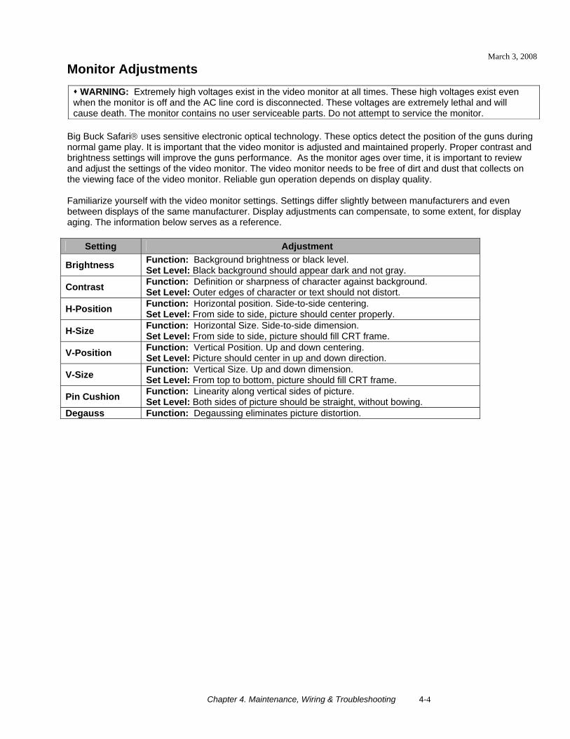
Monitor Adjustments
Big Buck Safari® uses sensitive electronic optical technology. These optics detect the position of the guns during normal game play. It is important that the video monitor is adjusted and maintained properly. Proper contrast and brightness settings will improve the guns performance. As the monitor ages over time, it is important to review and adjust the settings of the video monitor. The video monitor needs to be free of dirt and dust that collects on the viewing face of the video monitor. Reliable gun operation depends on display quality. Familiarize yourself with the video monitor settings. Settings differ slightly between manufacturers and even between displays of the same manufacturer. Display adjustments can compensate, to some extent, for display aging. The information below serves as a reference.
Setting Adjustment
Brightness Function: Background brightness or black level. Set Level: Black background should appear dark and not gray.
Contrast Function: Definition or sharpness of character against background. Set Level: Outer edges of character or text should not distort.
H-Position Function: Horizontal position. Side-to-side centering. Set Level: From side to side, picture should center properly.
H-Size Function: Horizontal Size. Side-to-side dimension. Set Level: From side to side, picture should fill CRT frame.
V-Position Function: Vertical Position. Up and down centering. Set Level: Picture should center in up and down direction.
V-Size Function: Vertical Size. Up and down dimension. Set Level: From top to bottom, picture should fill CRT frame.
Pin Cushion Function: Linearity along vertical sides of picture. Set Level: Both sides of picture should be straight, without bowing.
Degauss Function: Degaussing eliminates picture distortion.
WARNING: Extremely high voltages exist in the video monitor at all times. These high voltages exist even when the monitor is off and the AC line cord is disconnected. These voltages are extremely lethal and will cause death. The monitor contains no user serviceable parts. Do not attempt to service the monitor.
March 3, 2008
Chapter 4. Maintenance, Wiring & Troubleshooting 4-5
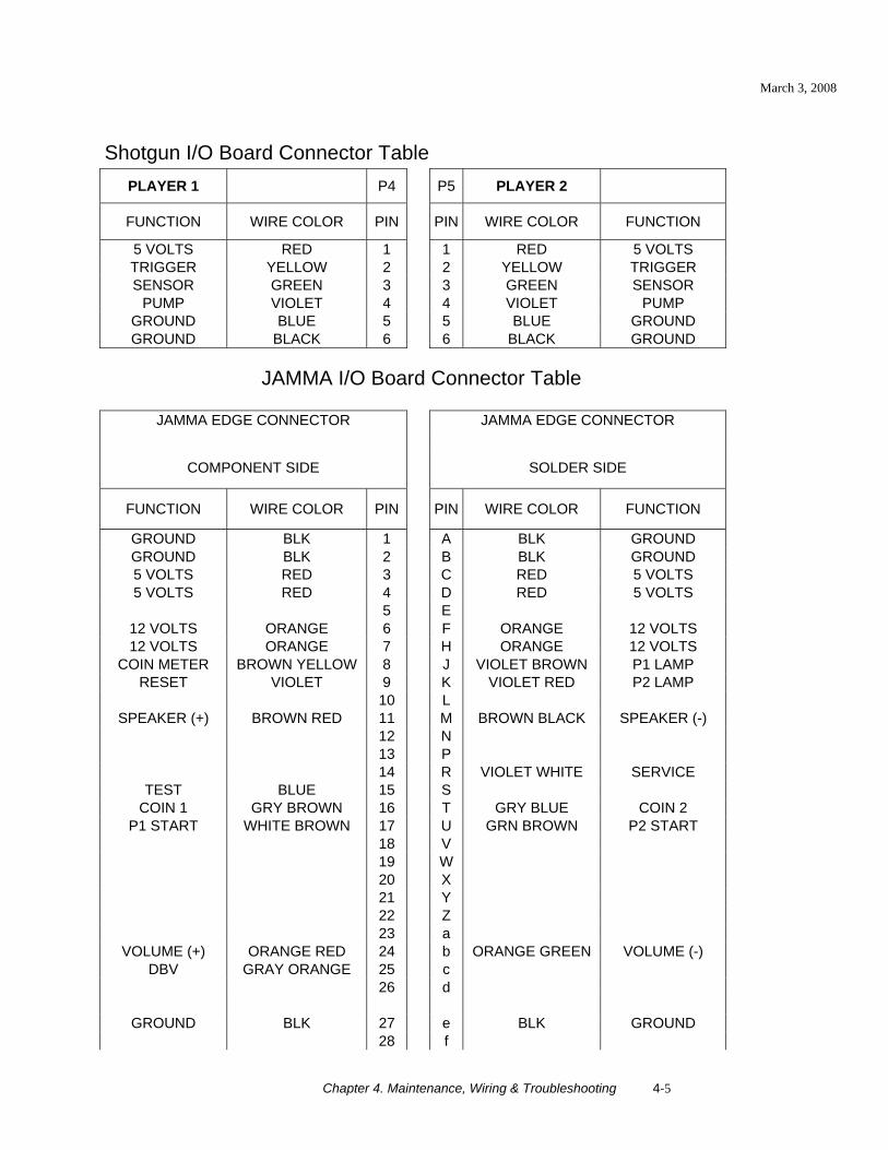
Shotgun I/O Board Connector Table
PLAYER 1 P4 P5 PLAYER 2
FUNCTION WIRE COLOR PIN PIN WIRE COLOR FUNCTION
5 VOLTS RED 1 1 RED 5 VOLTS TRIGGER YELLOW 2 2 YELLOW TRIGGER SENSOR GREEN 3 3 GREEN SENSOR
PUMP VIOLET 4 4 VIOLET PUMP GROUND BLUE 5 5 BLUE GROUND GROUND BLACK 6 6 BLACK GROUND
JAMMA I/O Board Connector Table
JAMMA EDGE CONNECTOR JAMMA EDGE CONNECTOR
COMPONENT SIDE SOLDER SIDE
FUNCTION WIRE COLOR PIN PIN WIRE COLOR FUNCTION
GROUND BLK 1 A BLK GROUND GROUND BLK 2 B BLK GROUND 5 VOLTS RED 3 C RED 5 VOLTS 5 VOLTS RED 4 D RED 5 VOLTS
5 E 12 VOLTS ORANGE 6 F ORANGE 12 VOLTS 12 VOLTS ORANGE 7 H ORANGE 12 VOLTS
COIN METER BROWN YELLOW 8 J VIOLET BROWN P1 LAMP RESET VIOLET 9 K VIOLET RED P2 LAMP
10 L SPEAKER (+) BROWN RED 11 M BROWN BLACK SPEAKER (-)
12 N 13 P 14 R VIOLET WHITE SERVICE
TEST BLUE 15 S COIN 1 GRY BROWN 16 T GRY BLUE COIN 2
P1 START WHITE BROWN 17 U GRN BROWN P2 START 18 V 19 W 20 X 21 Y 22 Z 23 a
VOLUME (+) ORANGE RED 24 b ORANGE GREEN VOLUME (-) DBV GRAY ORANGE 25 c
26 d
GROUND BLK 27 e BLK GROUND 28 f
March 3, 2008
Chapter 4. Maintenance, Wiring & Troubleshooting 4-6
Troubleshooting Guide
VIDEO GAME MACHINE Fails To Power-up The VIDEO GAME MACHINE will be in this failure mode when either the main AC power has failed, been disconnected, or the computer has failed to turn-on. The computer provides +5VDC and +12VDC for the VIDEO GAME MACHINE. Turning on the computer is controlled by the FUSE/WD board, p/n 500-00012-01.
1. Verify the VIDEO GAME MACHINE power switch is on. 2. Verify the AC line cord is plugged into a functional AC outlet. 3. Verify the AC outlet is the correct voltage for the VIDEO GAME MACHINE. 4. Verify the VIDEO GAME MACHINE is set to the correct voltage. There is a voltage switch on the
computer that needs to be set correctly. If this switch is set incorrectly and the VIDEO GAME MACHINE has been powered, damage to the computer may have occurred.
5. Verify the main AC power fuse for the VIDEO GAME MACHINE. This can be found on the lower back side of the VIDEO GAME MACHINE by the main power switch. If a fused failed, examine the VIDEO GAME MACHINE for a fault condition and repair the condition before replacing the fuse. For Continued protection, replace the fuse with identical UL rated fuse.
6. Verify the fuses on the FUSE / WD board, p/n 500-00012-01. These fuses protect the +5VDC and +12VDC power rails of the VIDEO GAME MACHINE. If a fused failed, examine the VIDEO GAME MACHINE for a fault condition and repair the condition before replacing the fuse. For Continued protection, replace the fuse with identical UL rated fuse.
7. Verify cable connectors inside the VIDEO GAME MACHINE. Look for cable connectors that are loose or not connected.
8. Contact Betson or your local distributor for additional service. You may have a failed computer or FUSE/WD board.
VIDEO GAME MACHINE Displays “NO VIDEO” Message On The Video Monitor The VIDEO GAME MACHINE will display this message when the video display is powered but the video monitor has no valid video signal.
1. Verify the VIDEO GAME MACHINE is set to the correct voltage. There is a voltage switch on the computer that needs to be set correctly. If this switch is set incorrectly and the VIDEO GAME MACHINE has been powered, damage to the computer may have occurred.
2. Verify cable connections inside the VIDEO GAME MACHINE, including the video and power cables of the computer, I/O board, FUSE/WD board and monitor.
3. Verify the fuses on the FUSE / WD board, p/n 500-00012-01. These fuses protect the +5v and +12v power rails of the VIDEO GAME MACHINE. If a fused failed, examine the VIDEO GAME MACHINE for a fault condition and repair the condition before replacing the fuse. Replace fuse with identical UL rated fuse.
4. Verify the I/O board has power. 5. Verify the FUSE/WD board has power. The +5VDCSTBY LED indicator should be on. 6. Verify the FUSE/WD board is running. There is a green LED indicator that should be blinking. 7. Contact Betson or your local distributor for additional service ce. You may have a failed computer,
FUSE/WD board or I/O board.
WARNING. Remove all power and disconnect AC line cord to VIDEO GAME MACHINE before servicing! Service performed by qualified service technician only. With power on do not connect or disconnect cables or connectorsVIDEO GAME MACHINE, damage to the VIDEO GAME
March 3, 2008
Chapter 4. Maintenance, Wiring & Troubleshooting 4-7
VIDEO GAME MACHINE Displays No Video On The Video Monitor The VIDEO GAME MACHINE will exhibit this failure when either the VIDEO GAME MACHINE is not powered, the monitor is not powered, the monitor is not correctly adjusted or the video monitor has failed.
1. Verify the VIDEO GAME MACHINE has powered-up. If not see 'VIDEO GAME MACHINE Fails To Power-up' in this troubleshooting section for more details.
2. Verify the cable connectors inside the VIDEO GAME MACHINE, paying close attention to the power and video signal cables of the video monitor.
3. Verify the video monitor has AC power. 4. Verify the contrast and brightness settings of the monitor. Make sure they are not set too low. 5. Contact Betson or your local distributor for additional service. You may have a failed monitor.
VIDEO GAME MACHINE Has No Sound If the game is running and there is no sound.
1. Verify that the audio levels are set to acceptable levels. This can done through the Diagnostic Menu System.
2. Verify the cable connections inside the VIDEO GAME MACHINE. Ensure that the audio cable from the computer is connected to the I/O board.
3. Verify the speaker cable is connected. 4. Verify the fuses on the FUSE / WD board, p/n 500-00012-01. These fuses protect the +5v and +12v
power rails of the VIDEO GAME MACHINE. If a fused failed, examine the VIDEO GAME MACHINE for a fault condition and repair the condition before replacing the fuse. Replace fuse with identical UL rated fuse.
5. Verify the I/O board has power. 6. Contact Betson or your local distributor for additional service. You may have a failed audio system.
VIDEO GAME MACHINE Monitor Displays 'CONNECT I/O' If the computer is unable to communicate with the I/O board, the 'Connect I/O' message will be displayed in the video display.
1. Verify that the I/O board has power. Check the fuses on the FUSE / WD board, p/n 500-00012-01. 2. Verify the cable connections inside the VIDEO GAME MACHINE. Verify the serial cable that connects the
I/O board to the computer is securely attached. 3. Power-cycle the VIDEO GAME MACHINE. 4. Contact Betson or your local distributor for additional service. You may have a failed I/O board.
VIDEO GAME MACHINE Monitor Displays 'INSERT DONGLE' This message indicates that the computer is unable to communicate with the security dongle that is located on the back of the computer.
1. Verify that the security dongle is attached to a USB port of the computer. 2. Contact Betson or your local distributor for additional service e. You may have a failed security dongle or
a USB port on the computer.
March 3, 2008
Chapter 4. Maintenance, Wiring & Troubleshooting 4-8
VIDEO GAME MACHINE Game Play is Slow, Freezes, or Resets. Numerous items can cause game play to exhibit freezing or slow play. Typical failure modes include excessive heat, corrupt drive, or failing hardware.
1. Verify that the security dongle is attached to a USB port of the computer. 2. Verify cable connections inside the VIDEO GAME MACHINE. Verify the serial cable that connects the I/O
board to the computer is securely attached. 3. Verify that the VIDEO GAME MACHINE is not running excessively hot. Verify that the cooling fan at the
top of the VIDEO GAME MACHINE is running and not obstructed. The back of the VIDEO GAME MACHINE must be at least one foot away from a wall in order to allow the vents on the VIDEO GAME MACHINE to breathe.
4. Verify that the computer is not running excessively hot. Verify that the computers cooling fans are running.
5. Verify the drive. This can be done via the Operators Menu. The drive can be re-imaged, by inserting the CD that was included with the VIDEO GAME MACHINE. See 'Drive Recovery Procedure' for instructions.
6. Verify that the games +5VDC +12VDC power rails are within +/- 5% tolerance. 7. Incorrect lamps in the coin door can cause the VIDEO GAME MACHINE to reset. Verify that the bulbs are
12 volt DC rated. 8. Contact Betson or your local distributor for additional service.
VIDEO GAME MACHINE Guns Do Not Work ProperlyAs part of VIDEO GAME MACHINE setup, you must calibrate the guns. Periodic gun calibration also allows you to optimize and verify gun performance. We recommend calibrating the guns every week of operation. Properly calibrated guns improve your collections.
1. Calibrate the guns and verify calibration. Verify that the guns switch's work in addition to the optics. Calibration is done via the Diagnostic Menu System.
2. Adjust the brightness and contrast of the monitor. A dark video image will cause the guns to malfunction. 3. Clean the video monitor of dirt and fingerprints. Examine the optic lens at the end of the gun. Dirt and
fingerprints on the guns optic lens will cause poor performance. 4. Verify cable connections in the VIDEO GAME MACHINE. Verify that the guns are properly connected to
the I/O board. Verify that the left gun is attached to the Left Gun connector and the right gun to the Right Gun connector.
5. Verify that the gun cable harness has not been damaged at the gun mount. 6. Contact Betson or your local distributor for additional service.
March 3, 2008
Chapter 4. Maintenance, Wiring & Troubleshooting 4-9
Maintenance, Wiring & Troubleshooting Notes
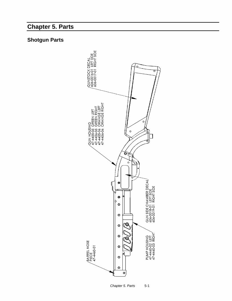
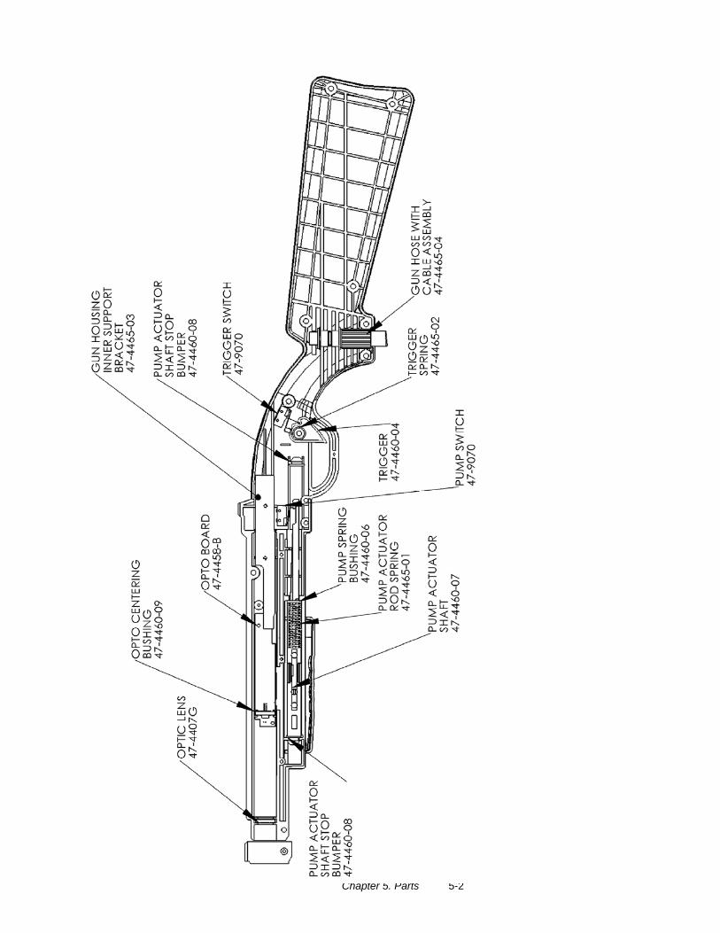
Chapter 5. Parts 5-1
Chapter 5. Parts
Shotgun Parts
Chapter 5. Parts 5-2
Chapter 5. Parts 5-3
Parts Notes
Chapter 5. Parts 5-4
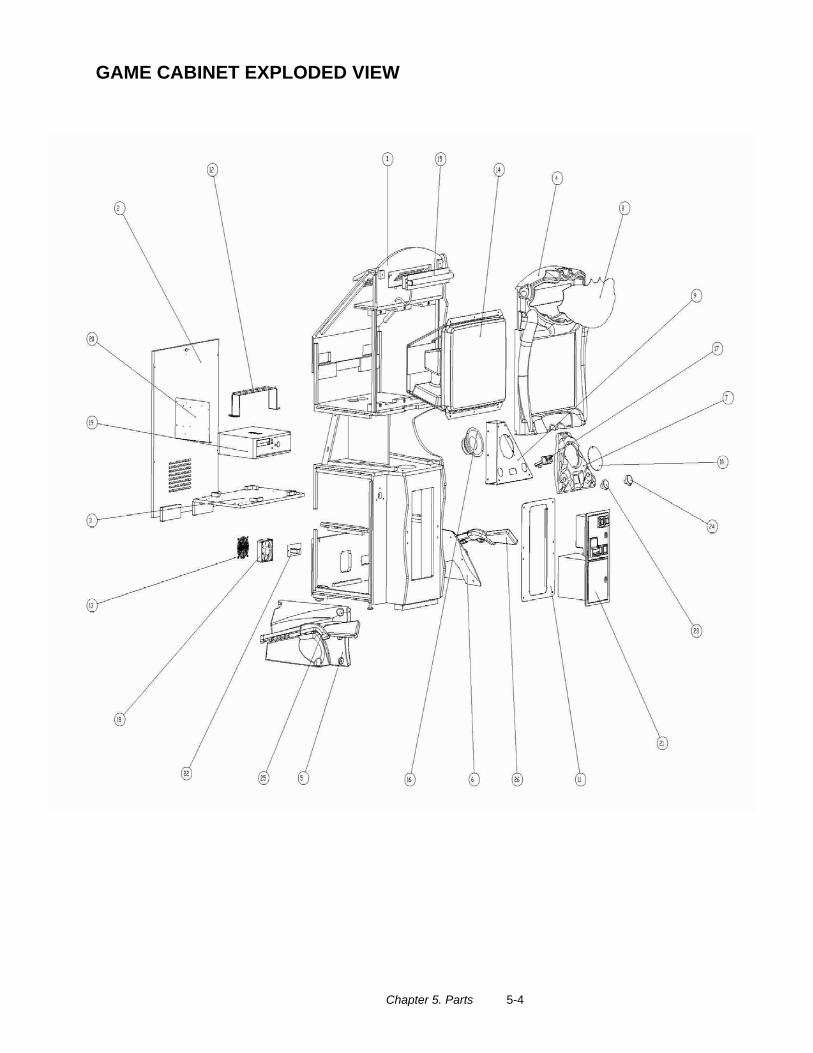
GAME CABINET EXPLODED VIEW
Chapter 5. Parts 5-5
BIG BUCK SAFARI I/O BOARD PN: 500-00001-02
BIG BUCK SAFARI WATCHDOG/FUSE BOARD PN: 520-00004-01
Chapter 5. Parts 5-6
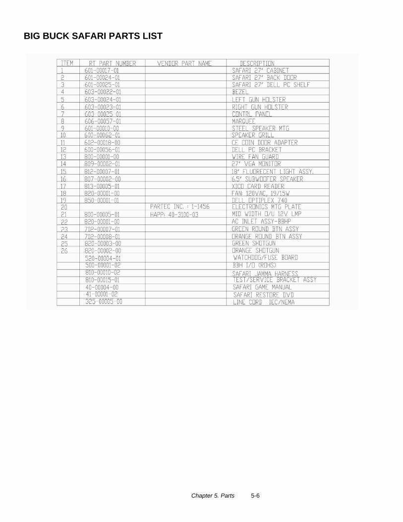
BIG BUCK SAFARI PARTS LIST

Copyright © 2008 by Raw Thrills, Inc. All rights reserved.