rc8325-adt wireless day/night hd camera · chapter 1 introduction ... oc835-adt outdoor day/night...
TRANSCRIPT
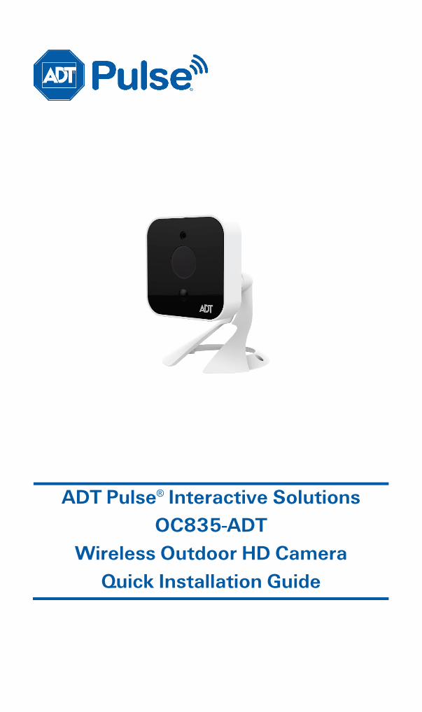
ADT Pulse® Interactive Solutions OC835-ADT
Wireless Outdoor HD Camera Quick Installation Guide
Table of Contents CHAPTER 1 INTRODUCTION ............................................................................ 3
Overview ............................................................................................................... 3 Physical Details ................................................................................................... 5 Package Contents ............................................................................................... 8
CHAPTER 2 BASIC SETUP ................................................................................. 9 Installation ............................................................................................................ 9
CHAPTER 3 ADT PULSE ENROLLMENT ....................................................... 11 Using a Wired Connection to Enroll the Camera ....................................... 11 Using a Wireless Connection Enroll the Camera ....................................... 15
CHAPTER 4 WALL MOUNTING ...................................................................... 19
APPENDIX A SPECIFICATIONS ...................................................................... 23 OC835-ADT Outdoor Day/Night HD Camera ............................................ 23 Regulatory Approvals ...................................................................................... 24
Property of ADT, LLC. Information accurate as of published date and is provided “as is” without warranty of any kind.
©2015 ADT LLC dba ADT Security Services. All rights reserved. ADT, the ADT logo, 800 ADT.ASAP and the product/service names listed in this document are marks and/or registered marks. Unauthorized use is strictly prohibited.
OC835-ADT-QIG-01 (09/15)
2 OC835-ADT Outdoor HD Camera Installation Guide
Chapter 1 Introduction This section provides information about the OC835-ADT Outdoor Day/Night HD Camera's features, components and capabilities.
Overview
The OC835-ADT is a true outdoor day/night wireless camera with HD resolution, 802.11n Wi-Fi connectivity and Wi-Fi Protected Setup (WPS) support. This camera is intended for use with ADT Pulse®.
Features
• Standalone Design. The camera is a standalone system with built-in CPU and video encoder. It requires only a power source and a connection to the ADT Pulse Gateway or ADT Total Security (TS) Base panel.
• Dual Video Support. The OC835-ADT supports H.264 and MJEPG video compression.
• Day/Night Switch: With the day/night switching feature, you can view and record images even at night.
• IR LED Support. The infrared LED can provide illumination for up to 6 meters, providing superior video quality under low-light conditions such as on cloudy days, or in the early morning or evening.
• PIR (Passive Infrared Sensor) Support. The embedded PIR Sensor senses infrared light radiating from human bodies in its field of view.
• Built-in Heater. The built-in heater ensures that the camera will continue to operate even in extremely cold outdoor climates. The heater turns on when the temperature falls below 42°F (6°C).
1
OC835-ADT Outdoor HD Camera Installation Guide 3

Chapter 1 Introduction
Wireless Features
• Supports 802.11n Wireless Standard. The 802.11n standard provides backward compatibility with the 802.11b and g standards.
• Supports WPS. Wi-Fi Protected Setup (WPS) can simplify the process of connecting the Wireless HD Camera to the wireless network by using the push button configuration.
• Wired and Wireless Network. The OC835-ADT can be connected to the Pulse network wirelessly. It can also be hardwired to the network.
4 OC835-ADT Outdoor HD Camera Installation Guide

Chapter 1 Introduction
Physical Details
Front
Figure 1: Front Panel
Light Sensor This is a hardware sensor to detect lux.
Lens The lens cannot be adjusted. Please ensure that the lens cover remains clean.
PIR Sensor This is a Passive Infrared sensor to detect motion.
Light Sensor
Lens
PIR Sensor
OC835-ADT Outdoor Day/Night HD Camera Installation Guide 5
Chapter 1 Introduction
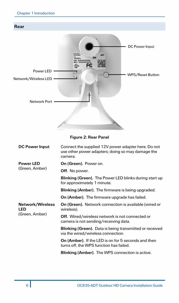
Rear
Figure 2: Rear Panel
DC Power Input Connect the supplied 12V power adapter here. Do not use other power adapters; doing so may damage the camera.
Power LED (Green, Amber)
On (Green). Power on.
Off. No power.
Blinking (Green). The Power LED blinks during start up for approximately 1 minute.
Blinking (Amber). The firmware is being upgraded.
On (Amber). The firmware upgrade has failed.
Network/Wireless LED (Green, Amber)
On (Green). Network connection is available (wired or wireless).
Off. Wired/wireless network is not connected or camera is not sending/receiving data.
Blinking (Green). Data is being transmitted or received via the wired/wireless connection.
On (Amber). If the LED is on for 5 seconds and then turns off, the WPS function has failed.
Blinking (Amber). The WPS connection is active.
Network Port
WPS/Reset Button
DC Power Input
Power LED
Network/Wireless LED
6 OC835-ADT Outdoor HD Camera Installation Guide

Chapter 1 Introduction
WPS/Reset Button This button serves two functions on the camera.
• WPS Pin Code Mode. When pressed and held for 5 seconds during the Pulse enrollment process, the camera creates an encryption-secured wireless connection.
• Reset. When pressed and held over 15 seconds, the camera reboots and the settings are restored to default values.
Network Port Use a Micro USB to RJ-45 Adapter Cable (not included) and a standard Ethernet cable (not included) to connect the camera to the Pulse Gateway or TS Base panel.
Note:
• Plugging in the Micro USB to RJ-45 Adapter Cable will disable the wireless interface. Only one interface can be active at any time.
• The Micro USB to RJ-45 Adapter Cable should only be connected or disconnected when the camera is powered OFF. Attaching or detaching the Micro USB to RJ-45 Adapter Cable while the camera is powered on does NOT switch the interface between wired and wireless.
OC835-ADT Outdoor Day/Night HD Camera Installation Guide 7

Chapter 1 Introduction
Package Contents
The following items are included in the package.
Figure 3: What’s in the Box
8 OC835-ADT Outdoor HD Camera Installation Guide

Chapter 2 Basic Setup This section provides information on how to assemble and configure the OC835-ADT Outdoor HD Camera.
Installation
1. Assemble the Camera
Attach the Camera Stand to the camera.
2. Make the Connection
Using a Wired Connection
If you are using a wired connection to the OC835-ADT, connect a Micro USB to RJ-45 Adapter Cable (not included) to the USB port of the camera. Then use a standard Ethernet cable (not included) to connect to the Pulse Gateway or Total Security (TS) Base panel.
Figure 4: Wired Network Connection
Using a Wireless Connection
The wireless (WPS) connection between the camera and the Pulse Gateway or Total Security (TS) Base panel is performed during the Pulse enrollment. This process is detailed starting on page 15.
Note: The Wireless and LAN interfaces cannot be used simultaneously. Making a wired LAN connection disables the wireless interface.
2
OC835-ADT Outdoor HD Camera Installation Guide 9

Chapter 2 Basic Setup
3. Power Up
Connect the supplied 12V power adapter to the camera and power up. Use only the power adapter provided. Using a different one may cause hardware damage.
CAUTION: Use only the power adapter provided. Using a different one can result in hardware damage.
The Power LED turns on briefly, and then starts blinking. (The Power LED will continue to blink during startup, which takes about one minute. After startup is completed, the Power LED should remain ON.)
4. Check the LEDs
• Power LED. At power up, the Power LED turns on briefly, and then starts blinking, which takes about one minute. After startup has completed, the Power LED remains on.
• Network/WPS LED. At power up, the Network/WPS LED is off. (The Network/WPS LED will flash amber when the camera attempts to connect wirelessly to the Pulse Gateway / TS Base. The Network/WPS LED will turn solid green when the wireless connection is successful.)
5. Enroll the Camera in ADT Pulse
This process is described in the next chapter, ADT Pulse Enrollment.
6. Mount the Camera
Place the camera in a location near a power source. For mounting on a wall using the mounting plate, see Chapter 4 Wall Mounting on page 19.
10 OC835-ADT Outdoor HD Camera Installation Guide

Chapter 3 ADT Pulse Enrollment This section provides examples of two different methods for enrolling the OC835-ADT Outdoor HD Camera into the ADT Pulse network. (1) The first method uses a wired connection to enroll the HD Camera to a Pulse Gateway or TS Base panel via the Pulse Portal or TS Installer App. (2) The second method uses WPS to wirelessly enroll the HD Camera to a Gateway or TS Base panel via the ADT Pulse Portal or TS Installer App. The WPS method is described beginning on page 15.
Using a Wired Connection to Enroll the Camera
1. Set up the camera, as described in the previous chapter.
2. Launch an Internet browser and log in to the Pulse portal or TS installer app.
3. Enter the Manage Devices screen using one of these methods:
• For the Pulse portal, select the System tab and click Manage Devices. • For the TS installer app, click the Pulse Devices link. The Manage Devices screen displays.
4. In the Manage Devices screen, click Cameras.
5. Click the Add button at the bottom of the screen.
3
OC835-ADT Outdoor HD Camera Installation Guide 11

Chapter 3 ADT Pulse Enrollment
6. Locate the camera’s MAC ID on the label on the rear of the camera.
7. On the Add Camera screen, enter the camera’s MAC ID. Do not click Continue at this time.
8. Ensure that the camera is connected to the device port of the Gateway using the Micro USB to RJ-45 Adapter Cable / Ethernet cable and connected to the supplied 12VDC power adapter.
9. After the Power and Network LEDs turn on solid green, click Continue.
12 OC835-ADT Outdoor HD Camera Installation Guide

Chapter 3 ADT Pulse Enrollment
10. Wait for the camera to add. It could take a few minutes, especially if an upgrade is required.
11. Assign the camera a unique name (usually based on the location of the camera) in the Name field, and then click the Save button at the upper right of the screen.
OC835-ADT Outdoor Day/Night HD Camera Installation Guide 13

Chapter 3 ADT Pulse Enrollment
12. The Cameras screen appears, now displaying the added camera.
13. At the top left of the screen, click Go Back.
14. You are returned to the Manage Devices screen. The total number of installed cameras has increased by one. Click Close.
15. Click Close again to confirm.
16. Disconnect the camera from the Gateway and remove from power.
17. Install the camera in its final location. For Wall Mounting, refer to Chapter 4.
14 OC835-ADT Outdoor HD Camera Installation Guide

Chapter 3 ADT Pulse Enrollment
Using a Wireless Connection Enroll the Camera
1. Set up the camera, as described in the previous chapter.
2. Launch an Internet browser and log in to the Pulse portal or TS installer app.
3. Enter the Manage Devices screen using one of these methods:
• For the Pulse portal, select the System tab and click Manage Devices. • For the TS installer app, click the Pulse Devices link.
The Manage Devices screen displays.
4. In the Manage Devices screen, click Cameras.
5. Click the Add Using WPS button, located at the bottom of the screen.
6. Locate the camera’s PIN number on the label on the rear of the camera.
OC835-ADT Outdoor Day/Night HD Camera Installation Guide 15

Chapter 3 ADT Pulse Enrollment
7. Enter the PIN number in the WPS PIN field.
8. Ensure that the camera is powered on, and then click the Continue button to initiate the WPS process.
The following screen appears.
9. Press and hold the WPS/RESET button on the camera for 5 seconds to establish a wireless connection.
The Network/WPS LED flashes amber as the TS Base attempts to connect to the camera. The wireless connection is successful when the Network/WPS LED turns solid green.
Note: You must complete the WPS connection within 2 minutes or else the process will time out. The time remaining is displayed in the upper left portion of the screen.
16 OC835-ADT Outdoor HD Camera Installation Guide

Chapter 3 ADT Pulse Enrollment 10. When the Camera Details screen appears, showing that the camera has been
enrolled, assign the OC835-ADT a unique name (usually based on the location of the camera) in the Name field, and then click Save.
The Pulse enrollment is complete. The newly-added device appears in the Cameras list.
11. At the top left of the screen, click Go Back.
12. Disconnect the camera from power.
13. Install the camera in its final location.
For Wall Mounting, refer to Chapter 4.
OC835-ADT Outdoor Day/Night HD Camera Installation Guide 17
Chapter 3 ADT Pulse Enrollment
If the Camera Continually Goes Offline
If after enrolling it the camera, it continually goes offline (Power LED blinks continually), the camera will automatically attempt to recover the wireless connection. If the camera cannot recover on its own, take the following measures to re-establish the Wi-Fi connection.
1. Power cycle the camera.
2. If the previous measure fails, move the Pulse Gateway closer to the camera, if possible.
3. If the previous measure fails, press the camera’s reset button for 15 seconds, and then re-enroll the camera into Pulse.
4. If the previous measure fails, install a Wi-Fi Range Extender model WN3000RPH-2ADPAS.
18 OC835-ADT Outdoor HD Camera Installation Guide

Chapter 4 Wall Mounting This section provides details for final mounting of the OC835-ADT Outdoor Day/Night HD Camera.
Note: Ensure that the camera is configured and enrolled in ADT Pulse before permanently mounting it.
1. Locate an unused, non-switchable, indoor outlet to plug the AC/DC Power
Adapter to plug into. This outlet should be located as close as possible to the location where the camera will be permanently mounted.
CAUTION: Do not plug in the power adapter until all the connections are completed and the camera is fully mounted.
2. Run the supplied power cable from the power outlet to the outdoor location
where the camera will be mounted.
3. At the location where the camera will be mounted, unscrew the camera stand and remove it from the camera.
4. Hold the stand at the location where you would like to mount the camera and mark the location of the two mounting holes.
5. Drill two holes on the mounting surface at the marked locations.
6. If using the anchors, insert them into the mounting holes.
7. Align the two mounting holes on the camera stand with the two holes and mount the stand to the surface using the two supplied screws.
Figure 5: Installing the Camera Stand
4
OC835-ADT Outdoor HD Camera Installation Guide 19

Chapter 4 Wall Mounting
8. Screw/attach the camera onto the camera stand.
Figure 6: Attaching the Camera
9. Connect the power cable into the back of the camera, and then insert the grommet between the camera and the power input cover, as shown in the following figures.
Figure 7: Connecting the Power Cable
CAUTION: Ensure that the grommet is positioned properly to prevent water from entering the camera.
10. Rotate the power input cover clockwise to tighten it, providing a watertight seal for the power cable.
Figure 8: Securing the Power Cable
20 OC835-ADT Outdoor HD Camera Installation Guide
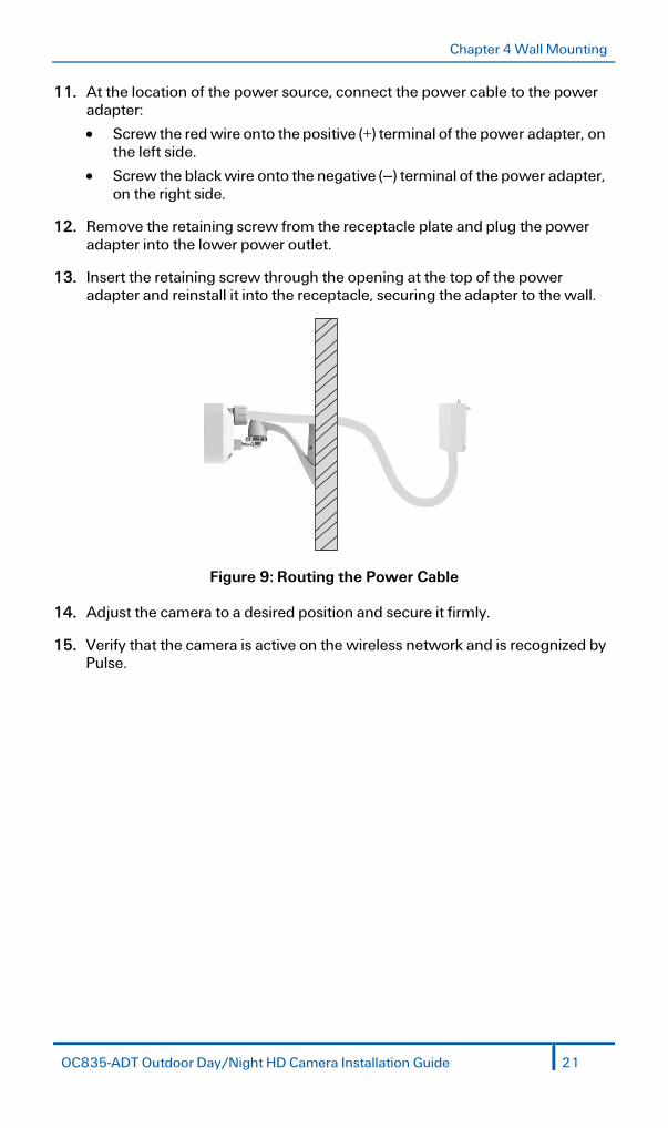
Chapter 4 Wall Mounting 11. At the location of the power source, connect the power cable to the power
adapter:
• Screw the red wire onto the positive (+) terminal of the power adapter, on the left side.
• Screw the black wire onto the negative (–) terminal of the power adapter, on the right side.
12. Remove the retaining screw from the receptacle plate and plug the power adapter into the lower power outlet.
13. Insert the retaining screw through the opening at the top of the power adapter and reinstall it into the receptacle, securing the adapter to the wall.
Figure 9: Routing the Power Cable
14. Adjust the camera to a desired position and secure it firmly.
15. Verify that the camera is active on the wireless network and is recognized by Pulse.
OC835-ADT Outdoor Day/Night HD Camera Installation Guide 21

Chapter 4 Wall Mounting
Mounting Suggestion: To get the best video quality for targets at night, make sure that the camera’s field of view does not include a large foreground object, such as tabletop or side wall. If installing on a tabletop, place the camera as close to the edge as possible. If installing on a wall, angle the camera so that a minimal portion of the wall is visible.
22 OC835-ADT Outdoor HD Camera Installation Guide

Appendix A
Specifications
OC835-ADT Outdoor Day/Night HD Camera
Dimensions W x H x D 2.99” x 2.99” x 1.91” (76mm x 76mm x 48.6mm)
Video Compression H.264 and MJPEG
Image Resolution 16:9 720p (1280x720), 640x360 4:3 XGA (1024x720), VGA (640x480), QVGA (320x240) Mixed Mode (720p, VGA, QVGA)
Operating Temperature
–40°F to 122°F (–40°C to 50°C) Heater operation: 42°F to 32°F (6°C to 0°C)
Storage Temperature –40°F to 158°F (-40°C to 70°C)
Network Protocols TCP/IP, HTTP, HTTPS, DHCP, UPnP, NTP, RTCP, DNS
Network Interface 1 RJ-45 LAN connection for Ethernet through Micro USB to RJ-45 Adapter Cable
Wireless Interface IEEE 802.11n/802.11b/802.11g compatible, WEP 64/128 bit, WPA/WPA2 personal security support
Button 1, WPS/Network
LEDs 2, Power and Network/WPS
IR LEDs 2
Power Adapter 12VDC/1.5A, 100 to 240VAC
A
OC835-ADT Outdoor HD Camera Installation Guide 23

Appendix
Regulatory Approvals
FCC Statement
This equipment generates, uses and can radiate radio frequency energy and, if not installed and used in accordance with the instructions, may cause harmful interference to radio communications. However, there is no guarantee that interference will not occur in a particular installation. If this equipment does cause harmful interference to radio or television reception, which can be determined by turning the equipment off and on, the user is encouraged to try to correct the interference by one of the following measures:
• Reorient or relocate the receiving antenna.
• Increase the separation between the equipment and receiver.
• Connect the equipment into an outlet on a circuit different from that to which the receiver is connected.
• Consult the dealer or an experienced radio/TV technician for help.
To assure continued compliance, any changes or modifications not expressly approved by the party responsible for compliance could void the user's authority to operate this equipment. (Example - use only shielded interface cables when connecting to computer or peripheral devices).
FCC Radiation Exposure Statement
This equipment complies with FCC RF radiation exposure limits set forth for an uncontrolled environment. This equipment should be installed and operated with a minimum distance of 20 centimeters between the radiator and your body.
This device complies with Part 15 of the FCC Rules. Operation is subject to the following two conditions:
(1) This device may not cause harmful interference, and
(2) This device must accept any interference received, including interference that may cause undesired operation.
This transmitter must not be co-located or operating in conjunction with any other antenna or transmitter.
24 OC835-ADT Outdoor HD Camera Installation Guide