rca consolette - americanradiohistory.com · locating and connecting equipment 7 to talk back to...
TRANSCRIPT
RCA Consolette
Type 76-B2(MI -11613-B)
Type 76-B4(MI -11613-C)
Power Supply(MI -11301-B)
RADIO CORPORATIOn OF AIflERICARCA VICTOR Division CAMDErl, fl. J.
1B-24454
BROADCAST EQUIPMENT
INSTRUCTIONS
RCA Consolette
Type 76-B2(MI -11613-B)
Type 76-B4(MI -11613-C)
Power Supply(MI -11301-B)
RADIO CORPOR ATIOrl OF A MERICF1RCA VICTOR Division CAMDE11, 11. J.
PRINTF'D IN U. S. A.
4136

Table of ContentsPage Page
Part I Installation Override Switch 16Emergency Program Channel 16
Technical Data iii Emergency "B" Supply 17
Description 1
Relay Operation 17Speaker Relay Interlock 17
Associated Equipment 2 Light Relay Interlock 17Microphones 2 Speaker Relay Interlock (Two or Three StudioMicrophone Stands 2 Operation) 19
Transcription Turntables 2 Light Relay Interlock (Two or Three StudioRecorders 2 Operation) 19
Recording Amplifiers 2 Speaker Relay Interlock (Single Studio Operation) 20Loudspeakers 2 Light Relay Interlock (Single Studio Operation). 20
Signal Lights and Relays 4 Suggested Operating Procedure 20Power Supply 4 To Place a Program on the Air 20Conduit Terminating Box 4 To Audition Studio B while Studio A is on the Air.. 216 db Pad for Telephone Lines 4
To Cue Studio B from Studio A and then placeBR -84 Rack or MI -11500 Wall Box 4 Studio B on the Air 21Radiotrons 4 To Cue Studio B from a Cue Line and then placeWall and Floor Outlets 4 Studio B on the Air 21
Locating and Connecting Equipment 7 To Talk Back to Studio A or Studio B 21
Connections to 76-B2 and 76-B4 Consolettes 7 Announcing 21
Audio Input Connections 8 Emergency Use of Monitor Amplifier 21
Audio Output Connections 8 Network Monitoring 21
Connecting Associated Equipment 9
Addition of Signal Lights 9 Part III-MI-11301-B Power SupplyStudio "On Air" and "On Audition" Signal Lights 9
Control Room On Air Relay 10 Technical Data 25Announce Booth Speaker and Signal Light Relays 10
Console Signal Lights 10 Description 25
Instantaneous Recorder 10 Installation 26Mounting 26
Conduit List for Types 76-B2 and 76-B4 Connections 26Consolettes 11 Loudspeaker Field Supply 26
Emergency Switch 26
Part II-Operation Hum Adjustment 27
General 15
Program Channel 15 Part IV MaintenanceAudition Channel 16
a. Monitoring 16 Inspection and Checking 31
b. Auditioning 16 Care of Pushbutton Switches 32
c. Cueing 16 Care of Key Switches 32
d. Talk -Back 16 Voltage Measurements 32
Remote Line Cue and Phone 16Replacement Parts 33
a. Cue 16
b. Phone 16 List of Parts 33
ii
List of IllustrationsPage
Figure 1-Type 76-62 Consolette with Door Open 1
Figure 2-Type 76-62 Consolette with Chassis Raised 3
Figure 3-6 db Pad for Telephone Lines 4
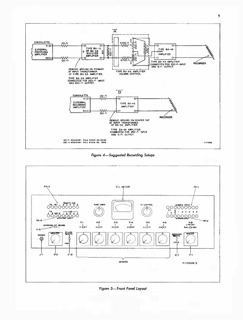
Figure 4-Suggested Recording Setups 5
Figure 5-Front Panel Layout .5
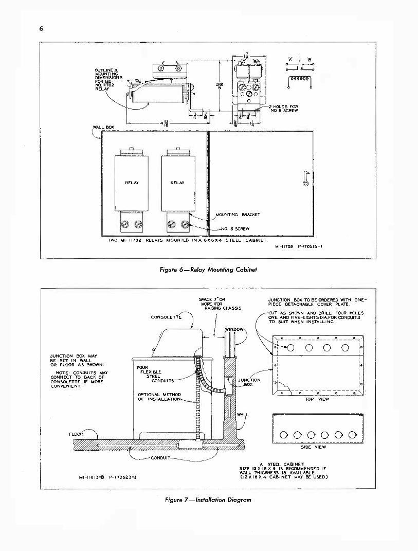
Figure 6-Relay Mounting Cabinet 6
Figure 7-Installation Diagram 6
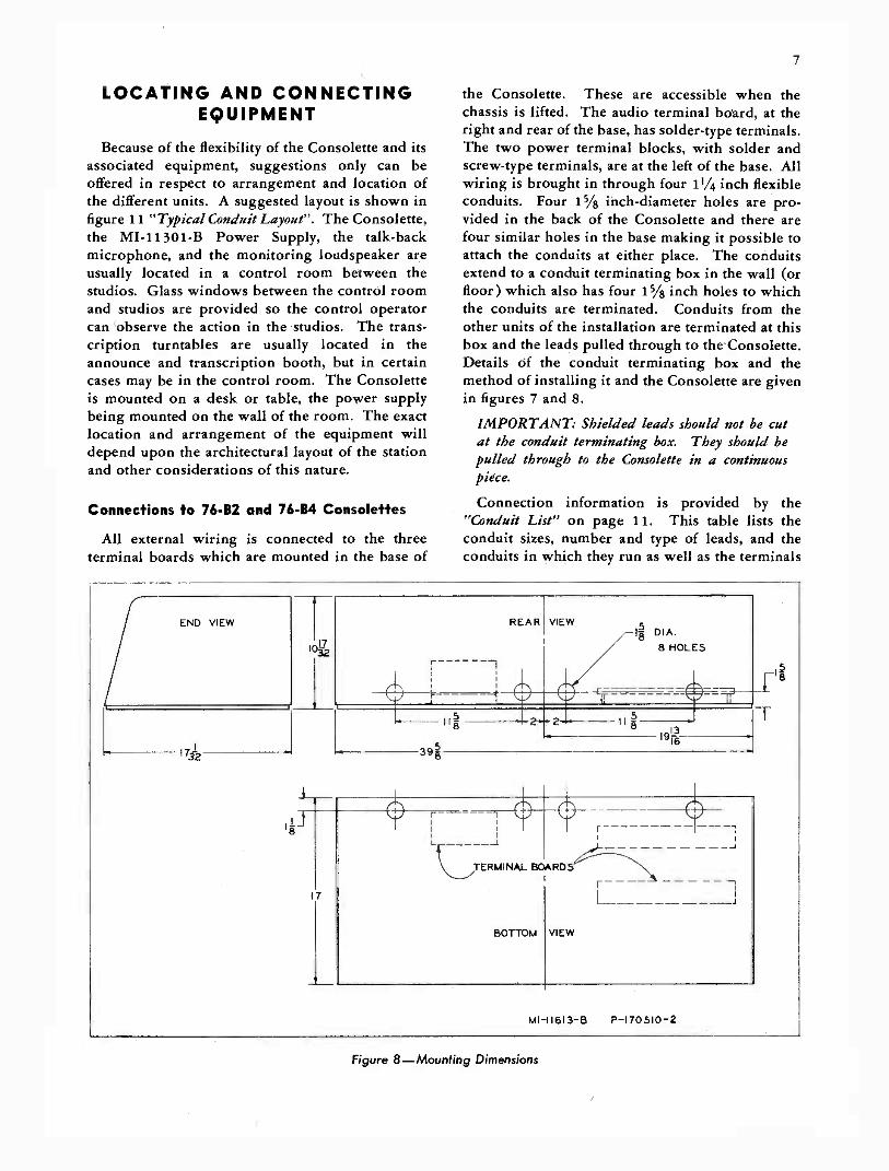
Figure 8-Mounting Dimensions 7
Figure 9-Schematic of VU Meter and Pad 8
Figure 10-Loudspeaker Connections 9
Figure 11-Typical Conduit Layout 13
Figure 12-Simplified Block Diagram of Types 76-62 and 76-64 Consolettes 14
Figure 13-Announce Booth Relay Connections 17
Figure 14-Simplified Schematic of Control Circuits 18
Figure 15-Simplified Block Diagram of Types 76-62 and 76-64 Consolettes 22
Figure 16-Schematic Diagram (W-131973) 23
Figure 17-MI-11301-B Power Supply 25
Figure 18-Mounting Dimensions (MI -11301-B Power Supply) 26
Figure 19-Interior View of Power Supply 27
Figure 20- Wiring Diagram (MI-1 1301-BPower Supply) 28
Figure 21-Schematic Diagram (MI-1 1301-BPower Supply) 29
Figure 22-Rear View of Power Supply Chassis 30
Figure 23-Relay Mounting Plate Wiring 33
Figure 24-Line Transformer Wiring 34
Figure 25-Preamplifier Mounting Plate Wiring 35
Figure 26-Program Amplifier Mounting Plate Wiring 36
Figure 27-Monitor Amplifier Mounting Plate Wiring 37
Figure 28-Front Panel Wiring (W-131969) 39
Figure 29-Overall Wiring Diagram (W-131681) 41

iii
TECHNICAL DATA
Power Required
One MI -11301-B Power Supply or a -c, d -c supplyas follows:
a. D -C Plate Supply
Term. Volts Milliamperes
Radiotrons*11 RCA -1620 or 11 RCA-6J7t2 RCA -1621 or 2 RCA-6F6t2 RCA -1622 or 2 RCA-6L6t
tMay be used when maximum uniformity ofcharacteristics, and minimum of microphonics,
116 375 62.0 hum, and distortion are not required.115114
210278
1.25.1
Inputs
104 285 42.0 a. Six 30- or 250 -ohm microphone inputs
105 220 4.6 (balanced )
Reg. 245 16.0 b. Six line inputs, 150, 300, and 600 ohms106 (balanced)
Emerg. 200 13.0 c. Two 250 -ohm transcription inputs (unbalanced )
b. A -C Filament Supply
Term. Volts Milliamperes
d. One 250 -ohm talk -back microphone input(balanced )
112 and 113 6.2 2.7 e. Five 20,000 -ohm monitor cue lines (balanced )109 and 110 6.2 1.6 Outputs107 and 108 6.2 0.3 a. One 500- to 600 -ohm line101 and 102
c. D -C Relay Supply
6.2 2.4b. Three 15 -ohm monitor linesc. One high -impedance headphone output (2,000
Term. Volts Milliamperes to 5,000 ohms)117 and 118 60 100
Line Output Noise Level
Gain
a. Microphone Input to Line Output: 112+2 dbb. Transcription Input to Line Output: 81 +1 1/2 db
c. Line Input to Line Output: 54+1 1/2 db
d. Microphone Input to Monitor Output:110+2 db
e. Line Input to Monitor Output: 54+2 db
f. Transcription Input to Monitor Output:80+2 db
g. Cue Input to Monitor Output: 34+2 db
h. Talk -back Input to Monitor Output: 95 +2 dbi. Line Output to Monitor Output: 33 ±2 db
j. Microphone Input to Emergency Line Output:91+2 db
k. Remote Line through Override: 27 +21/2 db
1. External Record: 90+2 db
m. Remote Talk -back: 77+2 db
Line Output Level
Normal: +18 dbm** with 0.5% rms harmonicdistortion from 50 to 7,500 cycles
Maximum: +26 dbm** with 1% rms harmonicdistortion from 50 to 7,500 cycles
Microphone Input at -50 dbm, to Line Outputat 18 dbm** output (68 db system gain): -68 dbMicrophone Input to Monitor Output at 4 watts(+36 dbm**) output (86 db system gain ): -68 db
Distortiona. Microphone Input to Line Output: 0.5% rms
harmonic distortion from 50 to 7,500 cycles,with normal output of +18 dbm**
b. Microphone Input to Monitor Output: 11/2%rms harmonic distortion from 50 to 7,500cycles at 4 watts output
Frequency Responsea. Microphone Input to Line Output: +2.0 db
from 30 to 15,000 cyclesb. Microphone Input to Monitor Output: +2 db
from 30 to 15,000 cycles (audition channel)
Monitor Power Outputa. 4.0 watts ( +36 dbm**) with 11/2% rms
harmonic distortion from 50 to 7,500 cyclesb. 8.0 watts ( +39 dbm**) with 3% rms harmonic
distortion from 50 to 7,500 cycles
Physical SpecificationsWidth 39 inches
*TRADEMARK RADIOTRON- REG. U. 5. PAT. OFF. BY RADIO CORPORATION OF AMERICA
**dbm = decibel level referred to one milliwatt sine wave power.
DepthHeightWeight
17 inches10 1/2 inches
135 pounds

1
TYPES 76-B2 AND 76-B4 RCA CONSOLETTES
PART I
Installation
DESCRIPTION
The Type 76-B2 (MI -11613-B ) and Type 76-B4(MI -11613-C) Consolettes have been designed foruse in Broadcast Audio installations to provide acomplete and flexible control system in one con-veniently arranged unit. All the controls necessaryfor switching and mixing the audio outputs ofmicrophones, transcription turntables and remote
lines, as well as for auditioning and monitoring,are contained in a single cabinet. The Consolettemay be used as a complete control system for asmall station, or to control a single studio in largerinstallations.
The Consolette consists of a metal cabinet con-taining four pre -amplifiers, a program amplifier, aneight -watt monitoring amplifier, two line trans-formers and three loudspeaker relays. A VU meter
P -2211-I
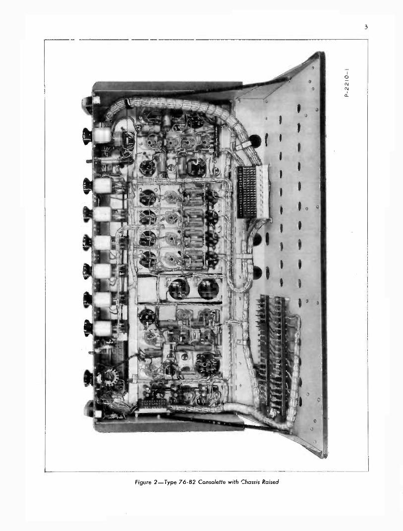
Figure 1-Type 76-82 Consolette with Door OpenIB-24454

2
attenuator controls, switches, and other controlsare mounted on a slanting front panel. An arrange-ment of switches makes it possible to use the VUmeter to check the condition of the tubes in theprogram channel.
The 76-B2 and 76-B4 Consolettes are similar inperformance and operation and the instructions forinstallation and operation apply to both typesunless otherwise specified.
The top of the Consolette may be opened toinspect and service the Radiotrons and relays orthe entire upper section, which is hinged at theback, may be lifted to expose the terminal boardsand the bottoms of the mounting plates. As may beseen in figure 2, three terminal boards are providedfor external connections. These are mounted onthe bottom section of the chassis and are accessiblewhen the upper section is lifted. The terminalboards are arranged so that the low-level audioterminals are separated from the high-level audioterminals and the power leads.
Five rubber -cushioned mounting plates are lo-cated on the hinged upper chassis as follows(left to right):
a. Relay Mounting Plate, on which are mountedthree relays and their associated equipment. Twoterminal boards, on which connections are made tochange over from two- (or three-) studio operationto single -studio operation are mounted underthis plate.
b. Monitor Amplifier Mounting Plate, onwhich are mounted the components of the monitoramplifier and the monitor amplifier booster stage.
c. Line Transformer Mounting Plate, on whichare mounted the two line transformers and asso-ciated resistors.
d. Preamplifier Mounting Plate, on which aremounted the four preamplifiers.
e. Program Amplifier Mounting Plate, onwhich are mounted the components of the programamplifier and the program amplifier booster stage.
ASSOCIATED EQUIPMENT
The additional apparatus required for operatingthis equipment will be determined partly by theparticular installation, depending on the number ofstudios and their arrangement. The installationdescribed in this book is designed to fulfill, ascompletely as possible, the average requirements ofthe type of broadcasting station for which theConsolette is designed. These instructions will also
serve as a guide to the customer whose installationis not exactly as described in these pages.
The associated equipment described below, orits equivalent, will be required for a completeinstallation.
Microphones
The Consolette is normally used with two micro-phones in each of two studios, a fifth microphone(for announcing) in the control room, and ifdesired, a sixth for an announce or transcriptionbooth. Terminals 9 and 10 and 47 and 48 may beconnected in parallel if the same microphone isused for control room announcing and talk -back.The RCA 44-BX, 74-B, MI -6203-B or 77-D ribbon-
type microphones are recommended for programpickup, the RCA Type 88-A Pressure Microphonefor control room announcing, and the RCA MI -6226 Aerodynamic Microphone and MI -6227Table Stand for the talk -back circuit.
Microphone Stands
The quality and type of stands required willdepend on the number and type of microphonesused. The most suitable program -type floor standfor use with all the above mentioned microphonesis the RCA Type 90-A. Lower priced stands suchas the KS-lA and MI -4068-D are also available.
The Type 91-A Announce Type Desk Stand(MI -4058-C) should be used with the 44-BXmicrophone only, and the 91-B Desk Stand (MI -4092 -C ) with the other microphones.
Transcription Turntables
The RCA 70-C2 Transcription Turntables arerecommended for the transcription booth or con-trol room installations. They may be used with theType 72-D or 72 -DX Recording Attachment.
Recorders
If the highest quality recording equipment isdesired, the 73-A or 73-B Deluxe Recorder isrecommended. Suggested recording setups andconnection information are shown in figure 4.
Recording AmplifiersThe Type BA -4B or 82-C1 Recording Amplifiers
are recommended for driving either the 70-C2Transcription Turntables, when used with therecording attachment, or the 73-A and 73-B re-corders. (See figure 4).
Loudspeakers
The RCA Type LC -1A loudspeakers should beused in the control room, lobby, studios, and
3
Figure 2-Type 76-82 Consolette with Chassis Raised

4
listening rooms where the greatest fidelity is re-quired. If high-fidelity reproduction is not requiredfor the studios and announce booth, other typesmay be used instead of the Type LC -1A in theselocations.
Signal Lights and RelaysThe MI -11706 series of studio signal lights are
recommended for use in the studios, announcebooth and control room. These lights are availablewith the inscriptions listed below and may beordered to suit the purpose for which the studioswill be used.
STUDIO WARNING LIGHTS
MI -Number Inscription
MI -11706.1MI -11706-2MI -11706-3MI -11706-4MI -11706-5
ON AIRREHEARSALAUDITIONSTAND BY
SILENCE
The relays and additional equipment required for installing this equipment are listed under Addition of SignalLights.
Figure 3-6 db Pad for Telephone Lines
Power Supply
The MI -11301-B Power Supply will furnish allthe voltages necessary to operate the 76-B2 or76-B4 Consolette and its associated relay controlsystem. The required voltages are listed underTechnical Data and instructions for installation andoperation of the power supply are given in part IIIof this book.
Conduit Terminating BoxA conduit terminating box of the type shown in
figure 7 is required to install the 76-B2 or 76-B4Consolette. In many cases this box is made by theelectrician or manufactured on special order. Insuch cases the mounting flanges may be turnedoutward instead of inside as shown in figure 7.
6DB Pad for Telephone Line
When used with some types of lines, a 600- to600 -ohm pad (MI -4171-29) should be connectedbetween the output terminals of the Consolette andthe telephone line jacks to permit the Consolette tooperate into a constant impedance at all times.
The resistors for a similar pad may be orderedas follows:
a. Resistor, 100 ohms RCA stock number34765 (4 required )
b. Resistor, 400 ohms RCA stock number30498 (2 required )
The resistors should be mounted in a rack or wallbox as described below and connected between the600 -ohm Line Out terminals of the Consolette andthe telephone line jacks as shown in figure 3.
BR -84 Rack or MI -11500 Wall Box
The 6 db telephone pad described above as wellas the line jacks and line equalizers may be mountedin an MI -11500 Wall Box or on a type BR -84 Rackif more space is required. The MI -11500 Wall Boxwill accommodate up to four MI -4645-A (Type33-A) or six MI -4646-A (Type 33-B) Jack Panelsand one MI -4162 (Type 56-E) Line Equalizer.
Radiotrons
The types and numbers of Radiotrons requiredare listed under Technical Data.
Wall and Floor Outlets
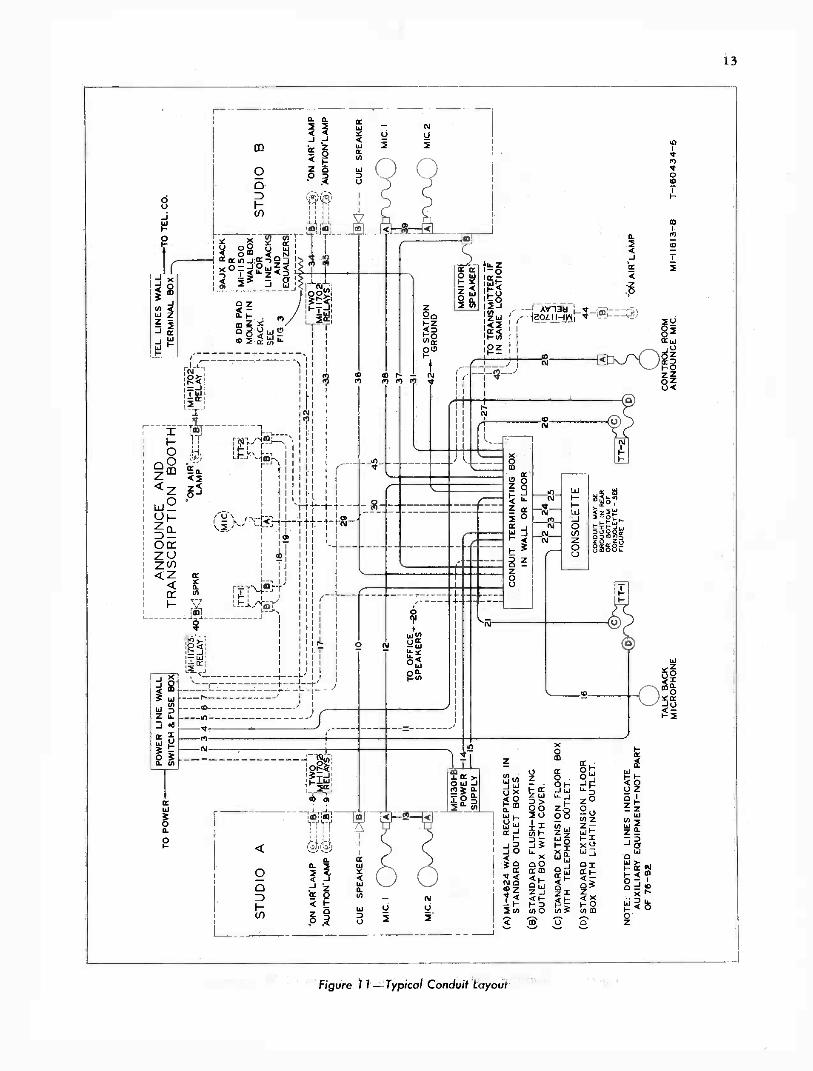
Wall and floor outlets for microphones, signallamps, loudspeakers, and turntables are shown inthe typical conduit layout in figure 11. Recom-mended outlets and boxes are listed in the drawing.
5
CONSOLETTE 120^
(41
EXTERNALRECORDINGAMPLIFIER
42
TYPE BA -IAz OR BA -2A 1;
- BOOSTER oAMPLIFIER
120"
REMOVE GROUND ON PRIMARYOF INPUT TRANSFORMEROF TYPE BA -2A AMPLIFIER.
TYPE BA -2A AMPLIFIERCONNECTED FOR 250" INPUTAND 600 ^ OUTPUT.
CONSOLETTE 120 -11-41 0--4AA/1--0 0
EXTERNALRECORDINGAMPLIFIER
"PC
L
1
TYPE BA -4A AMPLIFIERVOLUME CONTROL
"Bn
TYPE BA -4AAMPLIFIER
42 0--ANV--o 0120 "
REMOVE GROUND ON CENTER TAPOF INPUT TRANSFORMER
OF BA -4A AMPLIFIER.
TYPE BA -4A AMPLIFIERCONNECTED FOR 250 " INPUTAND 15" OUTPUT.
TYPE BA -4A-(30ND.
AMPLIFIER
TYPE BA -4A AMPLIF ERCONNECTED FOR 250." INPUTAND 15" OUTPUT.
RECORDER
RECORDER
120^ RESISTOR - RCA STOCK NO. 30199560 a RESISTOR - RCA STOCK NO. 5164 P -1743I3
Figure 4-Suggested Recording Setups
PN-3 V.U. METER PK-I
orbO "616-4,7, -6 6PK-4
OVERRIDMaRECCRO
N-9
noes
0MONITOR MOTE
PRO
TURK CHEOt VI. CONTROL
6770 067600TT ?
1 2 3 4 5 6i a
0 0 On9u9pu0 00T
*1 It2 Its3 K-4 K-5 Ki K-13 ----PK-2LINE OUT
A )33 AL33P Ar-CmP AcCMP A606 ASP ENG cCo REG
0 0 0 tEmraMASTER
J -I P-2 K -I0
MIXERS
K-7 P -I
P-170505-3
Figure 5-Front Panel Layout
6
OUTLINE S.MOUNTINGDIMENSIONSFOR MI-NO.1 I 702RELAY
01
"A; 'cc
172 HOLES FORNO. 6 SCREW
ALL BOX
TWO MI -11702 RELAYS MOUNTED IN A 6 X 6 X4 STEEL CABINET.MI -11702 P-170515-1
Figure 6-Relay Mounting Cabinet
CONSOLETTE
JUNCTION BOX MAYBE SET IN WALLOR FLOOR AS SHOWN.
NOTE: CONDUITS MAYCONNECT TO BACK OFCONSOLETTE IF MORECONVENIENT.
MI -11813-B P-170523-3
SPACE ORMORE FOR
RAISING CHASSIS
JUNCTION BOX TO BE ORDERED WITH ONE-PIECE DETACHABLE COVER PLATE.
CUT AS SHOWN AND DRILL FOUR HOLESONE AND FIVE-EIGHTS DIA.FOR CONDUITSTO SUIT WHEN INSTALLING.
TOP VIEW
0 0 0 0 0 0SIDE VIEW
A STEEL CABINETSIZE 12 X 18 X 6 IS RECOMMENDED IFWALL THICKNESS IS AVAILABLE.(12 X I 8 X4 CABINET MAY BE USED.)
Figure 7-Installation Diagram
7
LOCATING AND CONNECTINGEQUIPMENT
Because of the flexibility of the Consolette and itsassociated equipment, suggestions only can beoffered in respect to arrangement and location ofthe different units. A suggested layout is shown infigure 11 "Typical Conduit Layout". The Consolette,the MI -11301-B Power Supply, the talk -backmicrophone, and the monitoring loudspeaker areusually located in a control room between thestudios. Glass windows between the control roomand studios are provided so the control operatorcan observe the action in the studios. The trans-cription turntables are usually located in theannounce and transcription booth, but in certaincases may be in the control room. The Consoletteis mounted on a desk or table, the power supplybeing mounted on the wall of the room. The exactlocation and arrangement of the equipment willdepend upon the architectural layout of the stationand other considerations of this nature.
Connections to 76-B2 and 76-B4 Cansolettes
All external wiring is connected to the threeterminal boards which are mounted in the base of
the Consolette. These are accessible when thechassis is lifted. The audio terminal board, at theright and rear of the base, has solder -type terminals.The two power terminal blocks, with solder andscrew -type terminals, are at the left of the base. Allwiring is brought in through four 1)/4 inch flexibleconduits. Four 15/8 inch -diameter holes are pro-vided in the back of the Consolette and there arefour similar holes in the base making it possible toattach the conduits at either place. The conduitsextend to a conduit terminating box in the wall (orfloor) which also has four I% inch holes to whichthe conduits are terminated. Conduits from theother units of the installation are terminated at thisbox and the leads pulled through to the Consolette.Details of the conduit terminating box and themethod of installing it and the Consolette are givenin figures 7 and 8.
IMPORTANT: Shielded leads should not be cutat the conduit terminating box. They should bepulled through to the Consolette in a continuouspiece.
Connection information is provided by the"Conduit List" on page 11. This table lists theconduit sizes, number and type of leads, and theconduits in which they run as well as the terminals
END VIEW
10s2
f
r -,
REAR
a
VIEW
-Err
r'5 DIA.8 HOLES
f anyWar _- __
Iit,-
--i a
39x5
2 2 11
131916
M1-11613-13 P-170510-2
8
Figure 8-Mounting Dimensions

8
ZEROA DJ.
(2DB C8D8 C4DB 2DB S IDBIN
C
OFF 16 I
VU VVU
4VU
o REAR0 DECK
I
0 0 VOLUMEINDICATORCONTROL
(REAR VIEW)
-411--
OFFI
t
0 018 12 0VU VU 8o VU 0__
4VU
L
WIRES INDICATED BY DOTTEDLINES NOT TO BE CHANGED.
OFF
--I
VOLUMEINDICATOR
Z Z
MI -11613-B M-140853- I
Figure 9-Schematic of VU Meter and Pad
to which leads are connected. For example: conduitnumber 2 runs from the power line box to terminalsnumber 21 and 22 of the MI -11301-B PowerSupply. One pair of 600 -volt stranded, shielded,twisted leads is required. This conduit contains thea -c supply circuit and 1/2 inch conduit is used.
When attaching conduits, care should be taken toavoid damaging the shielded cables of the Con-solette. If necessary, the clamps may be loosenedand the shielded cables moved slightly when thefittings of the conduits are added. The clampsshould then be replaced.
When shipped from the factory the Consolette isconnected for two -studio operation. It may beconnected for single -studio operation by changingthe terminal board connections as shown infigure 10 and figure 14.
Audio Input Connections
The audio input terminals of the Consolette areconnected at the factory for microphone inputimpedances of 250 ohms. Should it be desired touse 30 -ohm microphones, the input connectionsmust be disconnected from the 250 -ohm primaryterminals of transformers T-1, T-2, T-3, and T-4
(terminals 1 and 6) and connected to the 30 -ohmprimary terminals (2 and 5).
As indicated in the "Schematic Diagram" figure15, terminals 1, 3, 5, and 7 of the input should beconnected to similar terminals of RCA microphonesfor proper phasing.
Line transformer T-9 and T-10 for Mixer No. 5and Mixer No. 6, respectively, are connected at thefactory for input impedances of 600 ohms. How-ever, the frequency response of many types ofremote lines can be improved (with or withoutequalizers) by operating them into 150 ohms.This can be done by connecting the line trans-formers (T-9 and T-10) for 150 ohms at theirprimaries as follows:
a. Remove the ground wire and the jumperbetween terminals 3-A and 1-B on both trans-formers.
b. Connect 3-A to 3-B and 1-A to 1-B on bothtransformers.
Audio Output Connections
The LINE OUT terminals of the Consolette aredesigned to operate into a 500- to 600 -ohm tele-phone line. When used with some types of tele-

9
(A) FOR SINGLE STUDIO OPERATION (2-1511 SPEAKERS) :*STRAP TERMINALS I& 2: * *CONNECT T-15 AS SHOWN:
(B) FOR
21
0304
TWO STUDIO OPERATION (3-1511 SPEAKERS):* STRAP TERMINALS 18.2,AND 33.4: * *CONNECT T-15 AS SHOWN:
91
62
4
(SEE NOTE NO 1)
(C) FOR THREE STUDIO OPERATION* STRAP TERMINALS 23.3:
01492
6304
(4-1511 SPEAKERS):* *CONNECT T-15 AS SHOWN:
* THESE TERMINALS ARELOCATED ON A SMALL 4 -TERMINAL BOARD ON THEBOTTOM OF THE RELAYMOUNTING PLATE.
**WHENMAKING OR CHANG-
ING CONNECTIONS 70 1-15,DO NOT DISTURB THE CON-NECTIONS TO TERM1NALSNQI, 3, 7, 84.12 T-15 (K -90104I)IS LOCATED ON THE MONITORAMPLIFIER MOUNTING PLATE.
MI -11613-B P -170519-L
Figure 10-Loudspeaker Connections
phone lines it is advantageous to insert a 6-db padbetween terminals 79 and 80 and the telephoneline. See the instructions for this under AssociatedEquipment.
Connecting Associated Equipment
A complete suggested layout of the Consoletteand associated equipment is illustrated in figure 11,Typical Conduit Layout. Arrangement of theconduits is shown in this figure and the leads whichrun in the conduits and the terminals to which theyare connected are shown in the Conduit List table.Note that all conduits are arranged so that a -cpower leads and audio leads are not run in thesame conduit and that low-level audio leads arenot run in the same conduit with high-level audio orloudspeaker field supply leads. Any variations onthe illustrated setup should be arranged to conformwith this practice.
Power for one, two, or three 100 -volt, 1,000 -ohm, 10 -watt loudspeaker fields may be obtainedfrom the MI -11301-B Power Supply. The instruc-tions given in this book under Power Supply shouldbe carefully followed. If speakers which have dif-ferent field voltage and power ratings are used aseparate field voltage power supply unit must beprovided.
ADDITION OF SIGNAL LIGHTSWhen installing signal lights in the two studios,
the relays may be connected directly to the terminalsprovided on the Consolette to obtain d -c energizingvoltage. Connections for Studio, Control Room,and Announce Booth light relays are describedbelow.
Studio "On Air" and "On Audition" Signal Lights
The following equipment is required to installsignal lamps in the two studios:
a. Four MI -11702 Relays and Capacitors.
b. Two mounting boxes (See figure 6 ).
c. Studio light equipment (See Signal Lightsand Relays under Associated Equipment).
The MI -11702 Relays are supplied with 0.5 mfcapacitors but these are not required for the studiolight relays since proper filtering for this circuit isprovided within the Consolette.
The relays should be mounted in metal boxes ofthe type specified in figure 6, which also showsmounting dimensions.
Mount the boxes near their respective studios andmake connections as follows:

10
CONNECTION TABLETerminal No. Relay Connection
124 Common terminal for studio "A""On Air" and "On Audition" relays
125 Studio "A" "On Air" relay123 Studio "A" "On Audition" relay127 Common terminal for studio "B"
"On Air" and "On Audition" relays126 Studio "B" "On Air" relay128 Studio "B" "On Audition" relay
Connect the a -c supply to the signal lights through theopen contacts of the MI -11702 Relays so that the lights willbe on when the relays are energized.
Control Room On Air Relay
If the control room "On Air" light is to be used,the following equipment will be required in addi-tion to that listed above:
a. One MI -11702 Relay and Capacitor.b. One mounting box (see figure 6).c. One resistor, 180 ohms, 20 watts; RCA
Stock number 17666.d. One "On Air" light. (See Signal Lights and
Relays under Associated Equipment).
The relay should be mounted in a metal box asspecified in figure 6 and installed near the controlroom. Conduits for the control room signal lightsare shown in figure 11. Relay energizing voltage issupplied by the voltage drop across the 180 -ohm,20 -watt resistor which is connected in series withthe high side of the relay supply circuit of theMI -11301-B Power Supply (see figure 14). Con-nections should be made as follows:
a. Connect the high side of the relay supplycircuit from the MI -11301-B Power Supply toterminal number 122 instead of 118 on theConsolette.
b. Connect terminal 118 to terminal 121.c. Connect the 180 -ohm, 20 -watt resistor and
0.5 mf capacitor across the control room "OnAir" relay.
d. Connect the control room "On Air" relayto terminals 121 and 122 on the Consolette.
e. Connect the a -c supply of the Control Room"On Air" light through the open terminals of theMI -11702 relay (marked "A" in fig. 6) so thatthe light will be on when the relay is on.
Announce Booth Speaker and Signal Light Relays
The Consolette has control terminals for theAnnounce Booth speaker and "On Air" Signal lightrelays but does not have terminals to supply d -c
energizing voltage for them. These relays may beinstalled and energizing power obtained as de-scribed below. The following equipment will berequired:
a. One MI -11702 Relay and Capacitor.b. One MI -11703 Relay and Capacitor.c. One Mounting Box (see figure 6).d. Two 180 -ohm, 20 -watt resistors.
(RCA stock No. 17666).e. Suitable light equipment.
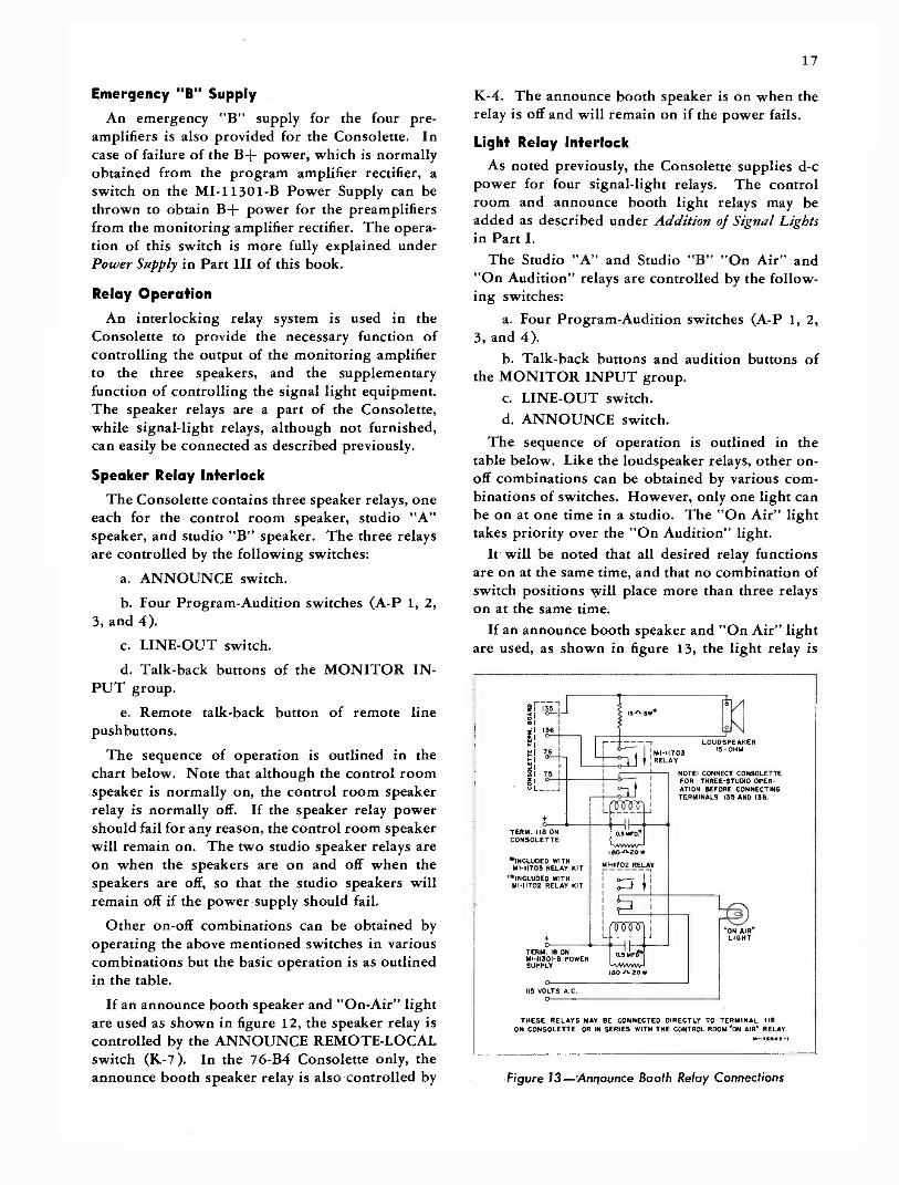
To obtain energizing voltage, the relays areconnected in series with the high side of the relaysupply circuit from the MI -11301-B Power Supply.The circuit may be connected as shown in figure 13if the Announce Booth relays only are to be used.If this circuit is used in conjunction with theControl Room light relay as shown in figure 14,connect terminal 76 to terminal 122 in addition tothe connections described under Control Room "OnAir" Relay and connect the Announce Booth relaysin series between terminal 18 of the MI -11301-BPower Supply and terminal 122 of the Consoletteas shown in figure 14.
The 0.5 mf capacitors and the 15 -ohm, 5 -wattresistors are included with the relay kits. Note that
connected for three -studiooperation before these relays are installed. Seefigure 13 for connections.
Console Signal Lights
Two plug buttons (one at either side of the meter )are inserted in the front panel of the Consolette andwiring is provided to permit the addition of twosignal lamp jacks. When these are used, signallights such as "Pre -Set" and "On Air" can beoperated from the master control room when theConsolette is used in large studio installations.
Terminals 67, 68, 69, and 70 may be used forexternal connections to the signal lamp jacks.
The following equipment is recommended:a. 2 lamp jacks, RCA stock no. 26562.b. 2 lamps, RCA stock no. 21332.c. 1 lamp cap, green, RCA stock no. 17931.d. 1 lamp cap, red, RCA stock no. 17930.
INSTANTANEOUS RECORDERThe RCA Type 72-C or 72-D Instantaneous Re-
corder, or the 73-B Deluxe Recorder may be usedwith the Type 76-B2 or 76-B4 Consolette forrecording auditions, broadcasts, or other material.Terminals 41 and 42, which must be bridged, are
11
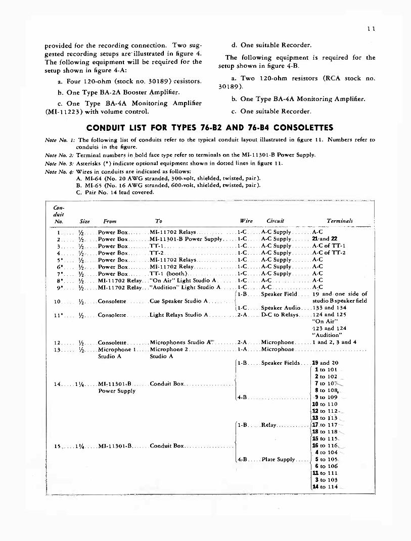
provided for the recording connection. Two sug-gested recording setups are- illustrated in figure 4.The following equipment will be required for thesetup shown in figure 4-A:
a. Four 120 -ohm (stock no. 30189) resistors.b. One Type BA -2A Booster Amplifier.
c. One Type BA -4A Monitoring Amplifier(MI -11223) with volume control. c. One suitable Recorder.
d. One suitable Recorder.
The following equipment issetup shown in figure 4-B.
a. Two 120 -ohm resistors30189).
required for the
(RCA stock no.
b. One Type BA -4A Monitoring Amplifier.
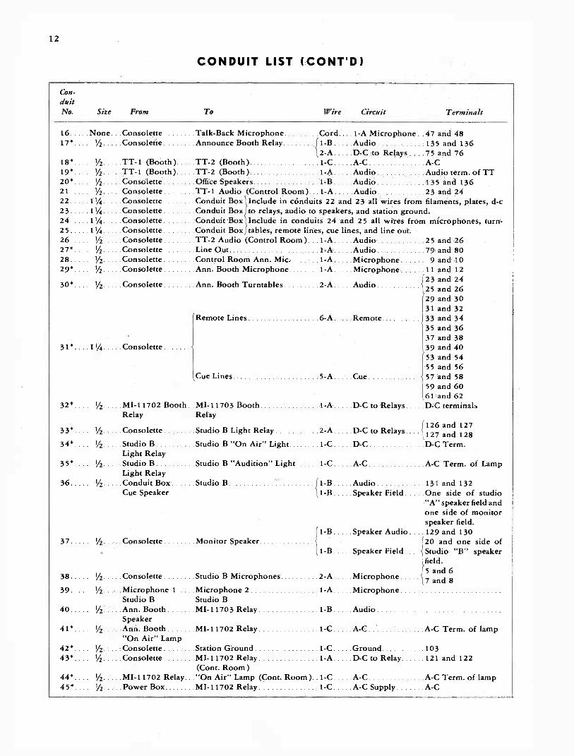
CONDUIT LIST FOR TYPES 76-B2 AND 76-B4 CONSOLETTESNote No. 1: The following list of conduits refer to the typical conduit layout illustrated in figure 11.
conduits in the figure.Note No. 2: Terminal numbers in bold face type refer to terminals on the MI -11301-B Power Supply.Note No. 3: Asterisks (*) indicate optional equipment shown in dotted lines in figure 11.Note No. 4: Wires in conduits are indicated as follows:
A. MI -64 (No. 20 AWG stranded, 300 -volt, shielded, twisted, pair).B. MI -65 (No. 16 AWG stranded, 600 -volt, shielded, twisted, pair).C. Pair No. 14 lead covered.
Numbers refer to
Con-duitNo. Size From To Wire Circuit Terminals
1 1/2 Power Box MI -11702 Relays 1-C A -C Supply A -C
2 1/2 Power Box MI -11301-B Power Supply 1-C A -C Supply 21 -and 22
3 1/2 Power Box TT -1 1-C A -C Supply A -C of TT -14 1/2 Power Box TT -2 1-C A -C Supply A -C of TT -2
5* 1/2 Power Box MI -11702 Relays 1-C A -C Supply A -C
6*. 1/2 Power Box MI -11702 Relay 1-C A -C Supply A -C
7* 1/2 Power Box TT -1 (booth ) 1-C A -C Supply A -C
8*.... 1/2 MI -11702 Relay "On Air" Light Studio A 1-C A -C A -C
9* 1/2 MI -11702 Relay "Audition" Light Studio A 1-C A -C A -C
1-B Speaker Field 19 and one side of10 1/2 Consolette Cue Speaker Studio A studio B speaker field
1-C Speaker Audio 133 and 13411* 1/2 Consolette Light Relays Studio A 2-A D -C to Relays 124 and 125
"On Air"123 and 124"Audition"
12 I/2 Consolette Microphones Studio A 2-A Microphone 1 and 2, 3 and 413 V2 Microphone I Microphone 2 I -A Microphone
Studio A Studio AI -B Speaker Fields. 19 and 20
1 to 1012 to 102
14 11/4 MI -11301-B Conduit Box 7 to 107Power Supply
4-B8 to 108,,9 to 109
10 to 11022 to 11213 to 113
1-B Relay 17 to 11718 to 11815 to 115
15 11/4 MI -11301-B Conduit Box 16 to 116.4 to 104
4-B Plate Supply 5 to 1056 to 106
11 to 1113 to 103
14 to 114
12
CONDUIT LIST (CONT'D)
Con-duitNo. Size From To Wire Circuit Terminals
16 None Consolette Talk -Back Microphone17*.... 1/2 Consolette Announce Booth Relay
18*.... 1/2 TT -1 (Booth)19* 1/2 TT -1 (Booth)20* 1/2 Consolette21 1/2
22 11/4
23 11/4
24 11/4
25 11/4
26 1/2
27* 1/2
28 1/2
29* 1/2
TT -2 (Booth )TT -2 (Booth)Office Speakers
Cord .. 1-A Microphone . 47 and 48{1-B Audio 135 and 1362-A D -C to Relays ....75 and 761-C A -C A -C1-A Audio Audio term. of TT1-B Audio 135 and 136
Consolette 'FT -1 Audio (Control Room ) 1-A Audio 23 and 24Consolette Conduit Box' Include in conduits 22 and 23 all wires from filaments, plates, d -cConsolette Conduit Box to relays, audio to speakers, and station ground.Consolette Conduit Box Include in conduits 24 and 25 all wires from microphones, turn-Consolette Conduit Box tables, remote lines, cue lines, and line out.Consolette n-2 Audio (Control Room ). 1-A AudioConsolette Line Out 1-A AudioConsolette Control Room Ann. Mic 1-A MicrophoneConsolette Ann. Booth Microphone 1-A Microphone
30* 1/2 Consolette Ann. Booth Turntables 2-A Audio
31*.
32*....
33*
34*
35*
36
37
38
39
40
41*
42*....43*
44*45*
11/4 Consolette
Remote Lines 6-A
Cue Lines 5-A
Remote
Cue
1/2 MI -11702 Booth M1-11703 Booth 1-A D -C to RelaysRelay Relay
i/2 Consolette Studio B Light Relay 2-A D -C to Relays.
I/2 Studio B Studio B "On Air" Light 1-C D -CLight Relay
IA Studio B Studio B "Audition" Light 1-C A -CLight Relay
1/2 Conduit Box Studio B AudioCue Speaker
{1-13
1-B Speaker Field
1-B Speaker Audio.
Consolette Monitor Speaker,1-B Speaker Field
1/2 Consolette Studio B Microphones 2-A Microphone
V2 Microphone 1 Microphone 2 1-A MicrophoneStudio B Studio B
1/2 Ann. Booth MI.11703 Relay 1-B AudioSpeaker
V2 Ann. Booth MI -11702 Relay 1-C A -C
"On Air" LampIA Consolette Station Ground 1-C Ground1/2 Consolette MI -11702 Relay 1-A D -C to Relay
(Cont. Room )1/2 MI.11702 Relay "On Air" Lamp (Cont. Room )..1.0 A -C1/2 Power Box MI -11702 Relay 1-C A -C Supply
25 and 2679 and 809 and 10
11 and 1223 and 2425 and 2629 and 3031 and 3233 and 3435 and 3637 and 38
(39 and 4053 and 5455 and 5657 and 5859 and 6061 and 62D -C terminals
{126 and 127127 and 128D -C Term.
A -C Term. of Lamp
131 and 132One side of studio"A" speaker field andone side of monitorspeaker field.129 and 13020 and one side ofStudio "B" speakerfield.5 and 67 and 8
A -C Term. of lamp
103121 and 122
A -C Term. of lampA -C
TO
PO
WE
R
ST
UD
IO A
PO
WE
R L
INE
WA
LLS
WIT
CH
8 F
US
E B
OX
i
12345¢7
1
`ON
AIR
LA
MP
it!,
-181
-13-
j TW
OM
H17
011
AU
D1T
ON
"LA
MP
-
CU
E S
PE
AK
ER
-
M1C
. 1
MIC
.2
AN
NO
UN
CE
AN
DT
RA
NS
CR
IPT
ION
BO
OT
HrM
IAIT
03!
II
IA
RE
LAy
r401
111!
...j
SP
KR
- I
II/
11 1
1
I1
19_i
-1
,
ri
`Th
!--
---1
7-
7-`,
16IC
)
ITT
-II
T:
,./It.
011-
'A
TE
L. L
INE
S W
ALL
TE
RM
INA
L B
OX
'ON
HM
I -11
702T
-LA
MP
--LA
MP
RE
LAY
YTS C
1BT
isT
J -32-
-
IN" M
1-11
301-
B-i
PO
WE
R14
-15
SU
PP
LY
(A)
MI -
4624
WA
LL R
EC
EP
TA
CLE
S IN
ST
AN
DA
RD
OU
TLE
T B
OX
ES
.
(B)
ST
AN
D A
RD
FLU
SH
-M
OU
NT
ING
OU
TLE
T B
OX
WIT
H C
OV
ER
.
(0 S
TA
ND
AR
D E
XT
EN
SIO
N F
LOO
R B
OX
WIT
H T
ELE
PH
ON
E O
UT
LET
.
(C)
ST
AN
DA
RD
EX
TE
NS
ION
FLO
OR
BO
X W
ITH
LIG
HT
ING
OU
TLE
T.
NO
TE
: DO
TT
ED
LIN
ES
IND
ICA
TE
AU
XIL
IAR
Y E
QU
IPM
EN
T -
NO
T P
AR
TO
F 7
6-13
8
11
10 12
r29
!
3045
TO
OF
FIC
E-2
.. 0-
,S
PE
AK
ER
S
Th
TO
TE
L. C
O.
9AJX
RA
CK
OR
DB
PA
DM
I -11
500
MO
UN
T IN
WA
LL B
OX
RA
CK
.F
OR
SE
ELI
NEJACKS
FIG
3A
ND
EQ
UA
LIZ
ER
S
ST
UD
IO B
4 T
WO
r34
at -
_:.:(
3;'O
N A
IR' L
AM
PM
H11
02-3
3R
ELA
YS
5---
Bi
-A
UD
ITIO
N"L
AM
P
36
--
21
38 3
TO
ST
AT
ION
42--
GR
OU
ND
CO
ND
UIT
TE
RM
INA
TIN
G B
OX
IN W
ALL
OR
FLO
OR
16
TA
LK B
AC
KM
ICR
OP
HO
NE
OT
T -
I
2122
4
CO
NS
OLE
TT
E
CO
ND
UIT
MA
Y B
EB
RO
UG
HT
IN R
EA
PO
R B
OT
TO
M O
FC
ON
SO
LET
TE
- S
EE
FIG
UR
E 7
TT
-2
-27
26 OO
431
1L
-4 -r 44 rk,
II kJ
'ON
AIR
- LA
MP
I
I 1
rTO
TR
AN
SM
ITT
ER
IFIN
SA
ME
LO
CA
TIO
N
MO
NIT
OR
SP
EA
KE
RB
CU
E S
PE
AK
ER
MIC
. I
MIC
2
CO
NT
RO
L R
OO
MA
NN
OU
NC
E M
IC.
M -
1161
3- I3
7-16
0434
-6

ON
AIR
NXXTIO
250
-It
MIX
ER
S
MIX
ER
5 I
KI
PG A 0
MIX
ER
2K
2
IM31
1
0 C
ML
ALL
ST
UD
IO L
IGH
TS
6 R
ELA
YS
AR
E E
XT
RA
AN
D O
PT
ION
AL.
RE
MO
TE
PR
E A
MP
3
O
AM
P. 4
MI
K3
I -O
.
ER
1(4
1-0-
rn'J
LAIT
OZ
RO
LP
GM
.R
MO
NIT
OR
VO
L. C
ON
TR
OL
01"e
--Im
coriO
R A
nsi
ME
TE
RP
LAT
E C
uRR
EN
TS
VU
CO
NT
RO
L
ro-
RL
I
1157
,
iftR
L
0- R
L 3
0 LI
NE
OU
T
0 M
ON
ITO
R O
UT
ALL
KE
Y S
WIT
CH
ES
8 R
ELA
YS
AR
EIN
TE
RLO
CK
ED
WH
ER
E R
EO
UIR
ED
FO
FT
ALK
BA
CK
CIR
CU
ITS
.
SE
E F
IG. 1
3F
OR
CO
NN
EC
TIO
NS
MIX
ER
5 0
- -0
-- -
0- -
0- -
0- -
0- -
0-LI
NE
INP
UT
TR
AN
SF
OR
ME
RS
PI(
I
MIX
ER
6P
-C
1-T
9
INP
UT
°-1
TT
2
MIX
ER
S
CU
E
°J1d
Tji
ritj 1
14-1
"F C
RE
MO
TE
LIN
ES
6
OV
ER
RID
E
K N6
Lb.
".".
-"43
O 9IS
O
PK
111,
_Jiti
rtei
tJy)
,JC
UE
LIN
ES
RE
MO
TE
(ET
ER
NA
LR
EC
O D
ING
AM
PLI
IER
AT
MO
NIT
OR
MR
15
TYPES 76-B2 AND 76-B4 RCA CONSOLETTES
PART II
Operation
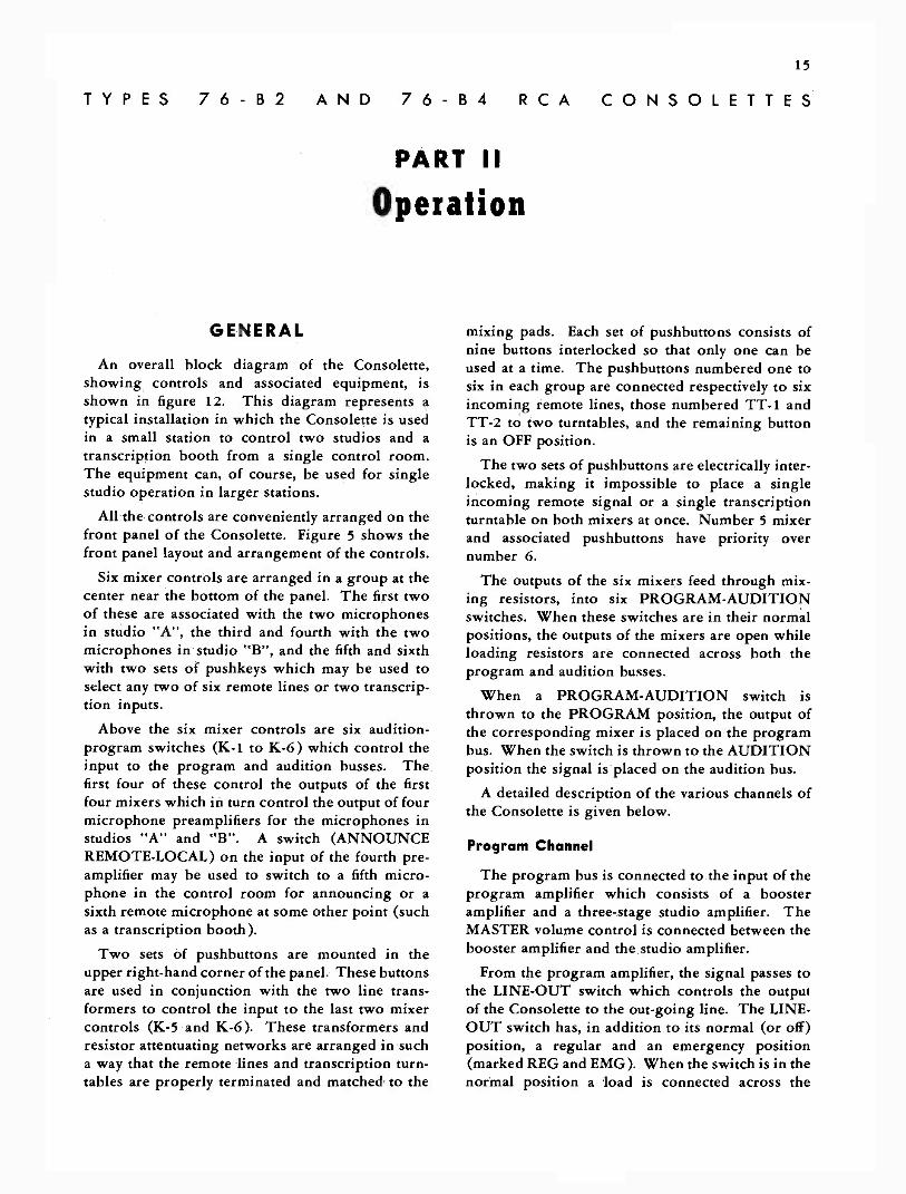
GENERAL
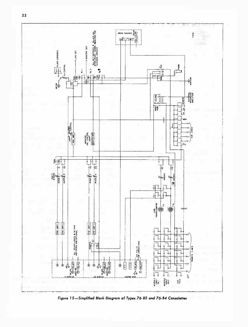
An overall block diagram of the Consolette,showing controls and associated equipment, isshown in figure 12. This diagram represents atypical installation in which the Consolette is usedin a small station to control two studios and atranscription booth from a single control room.The equipment can, of course, be used for singlestudio operation in larger stations.
All the controls are conveniently arranged on thefront panel of the Consolette. Figure 5 shows thefront panel layout and arrangement of the controls.
Six mixer controls are arranged in a group at thecenter near the bottom of the panel. The first twoof these are associated with the two microphonesin studio "A", the third and fourth with the twomicrophones in studio "B", and the fifth and sixthwith two sets of pushkeys which may be used toselect any two of six remote lines or two transcrip-tion inputs.
Above the six mixer controls are six audition -program switches (K-1 to K-6) which control theinput to the program and audition busses. Thefirst four of these control the outputs of the firstfour mixers which in turn control the output of fourmicrophone preamplifiers for the microphones instudios "A" and "B". A switch (ANNOUNCEREMOTE -LOCAL) on the input of the fourth pre-amplifier may be used to switch to a fifth micro-phone in the control room for announcing or asixth remote microphone at some other point (suchas a transcription booth).
Two sets of pushbuttons are mounted in theupper right-hand corner of the panel. These buttonsare used in conjunction with the two line trans-formers to control the input to the last two mixercontrols (K-5 and K-6). These transformers andresistor attentuating networks are arranged in sucha way that the remote lines and transcription turn-tables are properly terminated and matched to the
mixing pads. Each set of pushbuttons consists ofnine buttons interlocked so that only one can beused at a time. The pushbuttons numbered one tosix in each group are connected respectively to sixincoming remote lines, those numbered TT -1 andTT -2 to two turntables, and the remaining buttonis an OFF position.
The two sets of pushbuttons are electrically inter-locked, making it impossible to place a singleincoming remote signal or a single transcriptionturntable on both mixers at once. Number 5 mixerand associated pushbuttons have priority overnumber 6.
The outputs of the six mixers feed through mix-ing resistors, into six PROGRAM -AUDITIONswitches. When these switches are in their normalpositions, the outputs of the mixers are open whileloading resistors are connected across both theprogram and audition busses.
When a PROGRAM -AUDITION switch isthrown to the PROGRAM position, the output ofthe corresponding mixer is placed on the programbus. When the switch is thrown to the AUDITIONposition the signal is placed on the audition bus.
A detailed description of the various channels ofthe Consolette is given below.
Program Channel
The program bus is connected to the input of theprogram amplifier which consists of a boosteramplifier and a three -stage studio amplifier. TheMASTER volume control is connected between thebooster amplifier and the studio amplifier.
From the program amplifier, the signal passes tothe LINE-OUT switch which controls the outputof the Consolette to the out -going line. The LINE-OUT switch has, in addition to its normal (or off)position, a regular and an emergency position(marked REG and EMG). When the switch is in thenormal position a load is connected across the

16
program amplifier output. The volume indicator isconnected across this circuit.
When the LINE-OUT switch is in the REGULARposition, the output of the program amplifier is fedinto the outgoing line with the load removed andthe volume indicator still across the circuit. Thefunction of the LINE-OUT switch when in theEMERGENCY position is explained under Emer-gency Program Channel below.
When the PHONE -MONITOR switch is in thePROGRAM position, the program channel may bemonitored by means of the phone jack and head-phones.
Audition Channel
The audition channel of the Consolette is con-nected to one of a set of pushbuttons which deter-mine the input to the monitor amplifier. Thesebuttons, labeled MONITOR INPUT, are the lowerof the two sets of pushbuttons in the upper left-handcorner of the front panel. The MONITOR INPUTpushbuttons permit the following functions to beperformed.
a. Monitoring. One button (marked MON) con-nects the input of the monitor amplifier, throughproper bridging resistors,program amplifier. A program on the air may bemonitored in this manner.
b. Auditioning. One button (AUD), as men-tioned above, connects the output of the auditionbus into the monitoring amplifier, making it pos-sible to carry on an audition in one studio while theother studio is on the air.
c. Cueing. Five buttons, marked CUE andnumbered from 1 to 5, are provided to select anyone of five monitoring or cueing lines. These fivebuttons are mechanically interlocked with themonitor and audition buttons in such a way thatonly one can be on at a time. Any button, whenpressed, releases the button previously depressed.
d. Talk -back. Two buttons, marked TB andlettered A and B, are associated with the sevenbuttons mentioned above but not mechanicallyinterlocked with them. These buttons are used fortalk -back into studio A and studio B respectively.Either button, when pressed, connects the talk -back microphone to the input of the monitoramplifier and turns the proper studio speaker on.The speaker interlock is more fully explainedbelow. These buttons, although not mechanicallyinterlocked with the other seven MONITORINPUT buttons, are electrically interlocked so the
talk -back microphone is connected to the input ofthe monitor amplifier when either button is pressed.The connection previously made is restored whenthe button is released.
Remote Line Cue and Phone
The fourth set of interlocked pushbuttons (upperrow in the upper right-hand corner of the frontpanel) are used as follows:
a. Cue. The buttons marked CUE and num-bered 1 to 6 are connected to the six incomingremote lines. Pressing any of the buttons willconnect the output of the monitor amplifier into thecorresponding remote line provided the line is notalready in use.
b. Phone. The phone jack makes it possible tolisten to any of the remote lines by placing thePH. MON switch in the REMOTE position. It ispossible to talk to any of the remote lines by press-ing either of the two pushbuttons (marked TB)associated with the six remote cue buttons. Wheneither of these buttons is pressed, the talk -backmicrophone is connected to the input of the moni-toring amplifier and the output of the monitoringamplifier is connected into the remote lines. In thisway a conversation can be carried on with any ofthe six remote lines by putting the PH. MONswitch in the REMOTE position and holding downthe remote line talk -back buttons. The two buttonsare not mechanically interlocked with the sixremote line cue buttons. A ninth button is used foran off position.
Override Switch
When the switch marked OVERRIDE -OFF -RECORD is thrown to the OVERRIDE position, asignal on any of the six remote lines (not in use)will be heard in the monitor speaker.
Emergency Program Channel
If for some reason, the program amplifier of theConsolette should fail, the monitoring amplifiermay be used in the program channel.
When the LINE-OUT switch is thrown to theEMERGENCY position, the outgoing line is con-nected, through a bridging resistor, to the outputof the monitoring amplifier. Thus, by placing theprogram signal on the audition bus and pressingthe AUD button of the MONITOR INPUT themonitor amplifier will feed the outgoing line. TheVU meter will also be transferred to the output ofthe monitor amplifier so that the level can beproperly adjusted.
17
Emergency "B" Supply
An emergency "B" supply for the four pre-amplifiers is also provided for the Consolette. Incase of failure of the B+ power, which is normallyobtained from the program amplifier rectifier, aswitch on the MI -11301-B Power Supply can bethrown to obtain B+ power for the preamplifiersfrom the monitoring amplifier rectifier. The opera-tion of this switch is more fully explained underPower Supply in Part III of this book.
Relay Operation
An interlocking relay system is used in theConsolette to provide the necessary function ofcontrolling the output of the monitoring amplifierto the three speakers, and the supplementaryfunction of controlling the signal light equipment.The speaker relays are a part of the Consolette,while signal -light relays, although not furnished,can easily be connected as described previously.
Speaker Relay Interlock
The Consolette contains three speaker relays, oneeach for the control room speaker, studio "A"speaker, and studio "B" speaker. The three relaysare controlled by the following switches:
a. ANNOUNCE switch.b. Four Program -Audition switches (A -P 1, 2,
3, and 4).
c. LINE-OUT switch.
d. Talk -back buttons of the MONITOR IN-PUT group.
e. Remote talk -back button of remote linepushbuttons.
The sequence of operation is outlined in thechart below. Note that although the control roomspeaker is normally on, the control room speakerrelay is normally off. If the speaker relay powershould fail for any reason, the control room speakerwill remain on. The two studio speaker relays areon when the speakers are on and off when thespeakers are off, so that the studio speakers willremain off if the power supply should fail.
Other on -off combinations can be obtained byoperating the above mentioned switches in variouscombinations but the basic operation is as outlinedin the table.
If an announce booth speaker and "On -Air" lightare used as shown in figure 12, the speaker relay iscontrolled by the ANNOUNCE REMOTE -LOCALswitch (K-7). In the 76-B4 Consolette only, theannounce booth speaker relay is also controlled by
K-4. The announce booth speaker is on when therelay is off and will remain on if the power fails.
Light Relay InterlockAs noted previously, the Consolette supplies d -c
power for four signal -light relays. The controlroom and announce booth light relays may beadded as described under Addition of Signal Lightsin Part I.
The Studio "A" and Studio "B" "On Air" and"On Audition" relays are controlled by the follow-ing switches:
a. Four Program -Audition switches (A -P 1, 2,3, and 4).
b. Talk -back buttons and audition buttons ofthe MONITOR INPUT group.
c. LINE-OUT switch.d. ANNOUNCE switch.
The sequence of operation is outlined in thetable below. Like the loudspeaker relays, other on -off combinations can be obtained by various com-binations of switches. However, only one light canbe on at one time in a studio. The "On Air" lighttakes priority over the "On Audition" light.
It will be noted that all desired relay functionsare on at the same time, and that no combination ofswitch positions will place more than three relayson at the same time.
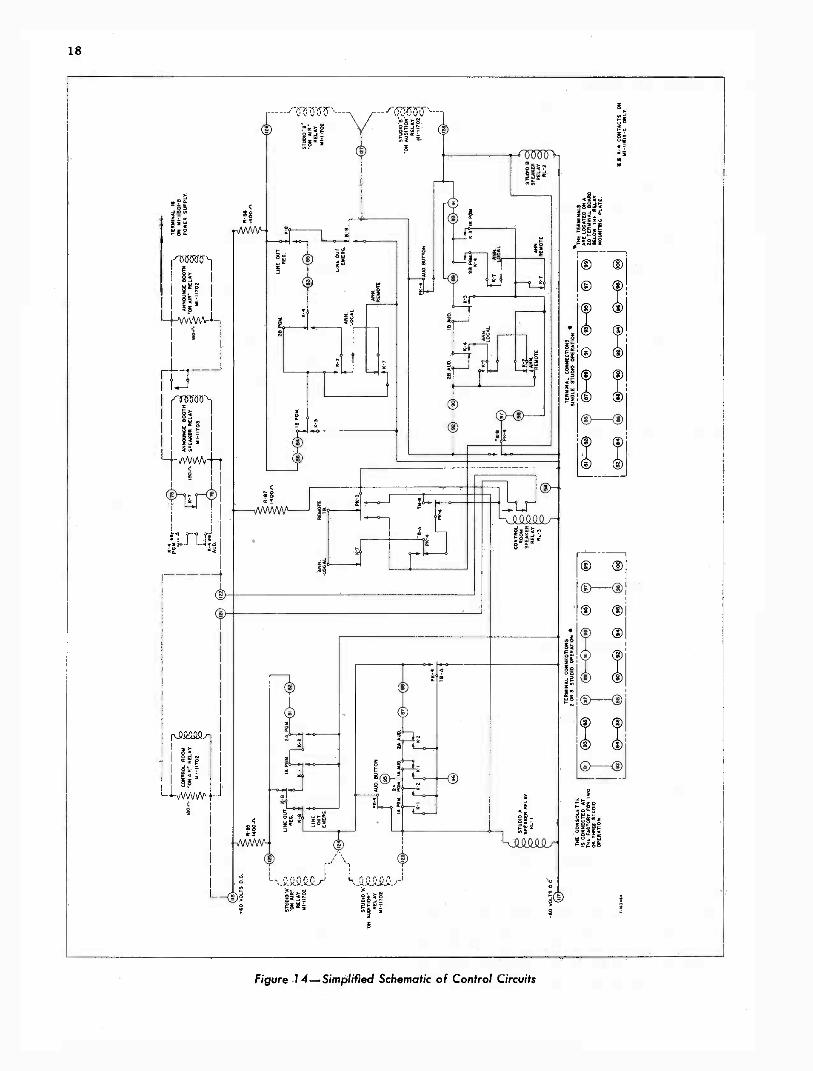
If an announce booth speaker and "On Air" lightare used, as shown in figure 13, the light relay is
136
76
75
TERM. 118 ONCONSOLETTE
*INCLUDED WITHMI -11703 RELAY KIT
t*INCLUDED WITHMI -11708 RELAY KIT
!MN 703RELAY
LOUOSPEA ER15 -OHM
NOTE' CONNECT CONSOLETTEFOR THREE -STUDIO OPER-ATION BEFORE CONNECTINGTERMINALS 135 AND 1313.
'ION AIR'.LIGHT
TERM. IS ONMI -11301-0 POWERSUPPLY
115 VOLTS A.C.
THESE RELAYS MAY BE CONNECTED DIRECTLY TO TERMINAL 118ON CONSOLETTE OR IN SERIES WITH THE CONTROL ROOM 'ON AIR" RELAY.
Figure 13-Announce Booth Relay Connections
18
10
io
0000%-'r
ire
0 0-0
00000r.511.
r' \I
Rt.c00000r
0
0
Figure 14-Simplified Schematic of Control Circuits
19
controlled by the speaker relay, the light being ononly when the speaker is off.
In the 76-B2 Consolette, the announcer boothspeaker relay is controlled by the ANNOUNCEswitch K-7. In the 76-B4 Consolette, the speakerrelay is controlled by both K-7 and K-4, the twoextra contacts on K-4 being used in conjunctionwith the announce booth relay control contacts inK-7. The additional contacts and connections are
shown in dotted lines in the Consolette SchematicDiagram, figure 16.
When a control room "On Air" light is used, asdescribed under Control Room On Air Light Relay,the light relay is operated by the control roomspeaker relay. The switches which control thisrelay are listed under Speaker Relay Interlock onpage 17. The control room "On Air" light is ononly when the control room speaker is off.
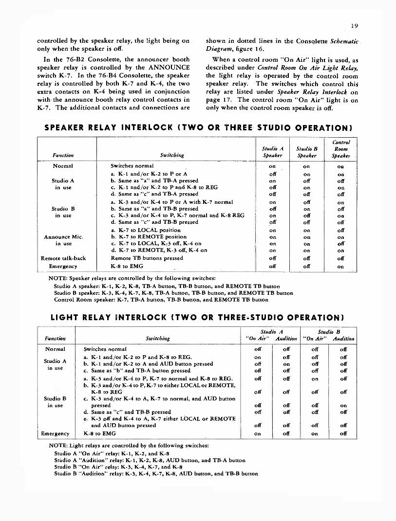
SPEAKER RELAY INTERLOCK (TWO OR THREE STUDIO OPERATION)
Function SwitchingStudio ASpeaker
Studio BSpeaker
ControlRoom
Speaker
Normal Switches normal on on ona. K-i and/or K-2 to P or A off on on
Studio A b. Same as "a" and TB -A pressed on off offin use c. K-1 and/or K-2 to P and K-8 to REG off on on
d. Same as "c" and TB -A pressed off off offa. K-3 and/or K-4 to P or A with K-7 normal on off on
Studio B b. Same as "a" and TB -B pressed off on offin use c. K-3 and /or K-4 to P, K-7 normal and K-8 REG on off on
d. Same as "c" and TB -B pressed off off offa. K-7 to LOCAL position on on off
Announce Mic. b. K-7 to REMOTE position on on onin use c. K-7 to LOCAL, K-3 off, K-4 on on on off
d. K-7 to REMOTE, K-3 off, K-4 on on on onRemote talk -back Remote TB buttons pressed off
Emergency K-8 to EMG off off on
NOTE: Speaker relays are controlled by the following switches:Studio A speaker: K-1, K-2, K-8, TB -A button, TB -B button, and REMOTE TB buttonStudio B speaker: K-3, K-4, K-7, K-8, TB -A button, TB -B button, and REMOTE TB buttonControl Room speaker: K-7, TB -A button, TB -B button, and REMOTE TB button
LIGHT RELAY INTERLOCK (TWO OR THREE -STUDIO OPERATION)
Function SwitchingStudio A
"On Air" AuditionStudio B
"On Air" Audition
Normal Switches normal off off off off
Studio Aa. K-1 and/or K-2 to P and K-8 to REG.b. K-1 and/or K-2 to A and AUD button pressed
onoff
offon
offoff
offoffin use c. Same as "b" and TB -A button pressed off off off off
Studio B
a. K-3 and/or K-4 to P, K-7 to normal and K-8 to REG.b. K-3 and/or K-4 to P, K-7 to either LOCAL or REMOTE,
K-8 to REGc. K-3 and/or K-4 to A, K-7 to normal, and AUD button
off
off
off
off
on
off
off
off
in use pressed off off off ond. Same as "c" and TB -B pressede. K-3 off and K-4 to A, K-7 either LOCAL or REMOTE
off off off off
and AUD button pressed off off off offEmergency K-8 to EMG on off on off
NOTE: Light relays are controlled by the following switches:Studio A "On Air" relay: K-1, K-2, and K-8Studio A "Audition" relay: K-1, K-2, K-8, AUD button, and TB -A buttonStudio B "On Air" relay: K-3, K-4, K-7, and K-8Studio B "Audition" relay: K-3, K-4, K-7, K-8, AUD button, and TB -B button
20
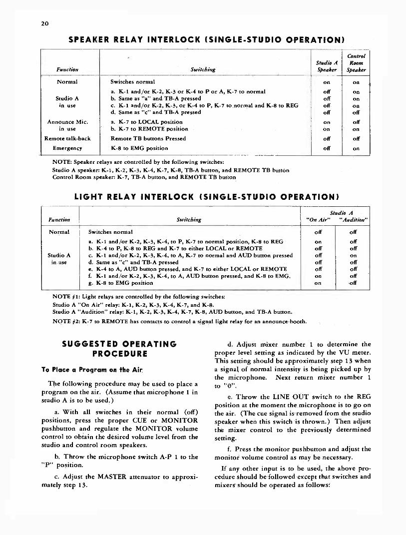
SPEAKER RELAY INTERLOCK (SINGLE -STUDIO OPERATION)
Function SwitchingStudio ASpeaker
ControlRoom
Speaker
Normal Switches normal on on
a. K-1 and/or K-2, K-3 or K-4 to P or A, K-7 to normal off onStudio A b. Same as "a" and TB -A pressed off onin use c. K-1 and/or K-2, K-3, or K-4 to P, K-7 to normal and K-8 to REG off on
d. Same as "c" and TB -A pressed off off
Announce Mic. a. K-7 to LOCAL position on offin use b. K-7 to REMOTE position on on
Remote talk -back Remote TB buttons Pressed off off
Emergency K-8 to EMG position off on
NOTE: Speaker relays are controlled by the following switches:Studio A speaker: K-1, K-2, K-3, K-4, K-7, K-8, TB -A button, and REMOTE TB buttonControl Room speaker: K-7, TB -A button, and REMOTE TB button
LIGHT RELAY INTERLOCK (SINGLE -STUDIO OPERATION)
Function SwitchingStudio A
"On Air" "Audition"
Normal Switches normal off off
a. K-1. and/or K-2, K-3, K-4, to P, K-7 to normal position, K-8 to REG on offb. K-4 to P, K-8 to REG and K-7 to either LOCAL or REMOTE off off
Studio A c. K- t and/or K-2, K-3, K-4, to A, K-7 to normal and AUD button pressed off onin use d. Same as "c" and TB -A pressed off off
e. K-4 to A, AUD button pressed, and K-7 to either LOCAL or REMOTE off offf. K-1 and /or K-2, K-3, K-4, to A, AUD button pressed, and K-8 to EMG. on offg. K-8 to EMG position on off
NOTE #1: Light relays are controlled by the following switches:Studio A "On Air" relay: K-1, K-2, K-3, K-4, K-7, and K-8.Studio A "Audition" relay: K-1, K-2, K-3, K-4, K-7, K-8, AUD button, and TB -A button.
NOTE #2: K-7 to REMOTE has contacts to control a signal light relay for an announce booth.
SUGGESTED OPERATINGPROCEDURE
To Place a Program on the Air
The following procedure may be used to place aprogram on the air. (Assume that microphone 1 instudio A is to be used.)
a. With all switches in their normal (off)positions, press the proper CUE or MONITORpushbutton and regulate the MONITOR volumecontrol to obtain the desired volume level from thestudio and control room speakers.
b. Throw the microphone switch A -P 1 to the"P" position.
c. Adjust the MASTER attenuator to approxi-mately step 13.
d. Adjust mixer number 1 to determine theproper level setting as indicated by the VU meter.This setting should be approximately step 13 whena signal of normal intensity is being picked up bythe microphone. Next return mixer number 1
to "0".e. Throw the LINE OUT switch to the REG
position at the moment the microphone is to go onthe air. (The cue signal is removed from the studiospeaker when this switch is thrown.) Then adjustthe mixer control to the previously determinedsetting.
f. Press the monitor pushbutton and adjust themonitor volume control as may be necessary.
If any other input is to be used, the above pro-cedure should be followed except that switches andmixers should be operated as follows:

21
SWITCH AND MIXER TABLE
Input Switch Mixer
Mic. 1, studio A Mic. A -P no. 1 to P 1
Mic. 2, studio A Mic. A -P no. 2 to P 2
Mic. 1, studio B Mic. A -P no. 3 to P 3
Mic. 2, studio B Mic. A -P no. 4 to P and 4
ANN sw. to norm.Remote lines Mic. A -P no. 5 or 6 to
P and, correspond-ing input P -K 1 orP -K 2 5 or 6
TranscriptionTurntable no. 1
A -P 5 or A -P 6 to P,
and TT -1 5 or 6
TranscriptionTurntable no. 2
A -P 5 or A -P 6 to P,
and TT -2 5 or 6
To Audition Studio B while Studio A is on the Air
To audition studio B while studio A is on the air,proceed as follows:
a. With the talk -back and monitor pushbuttonsin the normal (off) positions, press the AUD push-button and throw the microphone switch, A -Pnumber 3, to the A position.
b. Adjust mixer number 3 and the monitorvolume control to obtain a suitable output from thecontrol room loudspeaker.
To Cue Studio B from Studio A and then placeStudio B on the Air
Assuming that microphone number 1 in studio Ais in use and it is desired to place microphonenumber 1 in studio B on the air, it is necessary toperform only the following steps at the momentstudio B is to go on the air (since studio B loud-speaker is already receiving the signal fromstudio A ).
a. Close mixer number 1.
b. Throw microphone switch A -P number 3to the P position.
c. Adjust mixer number 3 to the proper level asindicated by the VU meter.
To Cue Studio B from a Cue Line and then placeStudio B on the Air
Assuming that microphone number 1 is in use instudio A and that studio A is on the air, proceedas follows:
a. Press the proper CUE line pushbutton andregulate the Monitor volume control to obtain thedesired volume from studio B speaker. The cueline may be monitored by the control room speaker.
b. At the moment studio B is to go on the
air, perform the following operations in quicksuccession:
(1) Close mixer number 1.(2) Throw microphone switch A -P number
3 to the P position. (Assuming microphonenumber 1 in studio B is to go on the air).
(3) Adjust mixer number 3 to the properlevel as indicated by the VU meter.
To Talk Back to Studio A or Studio BTo talk back to either studio A or studio B
proceed as follows:Press the talk -back pushbutton A or B according
to the studio desired, and talk into the talk -backmicrophone. This cannot be done when eitherstudio is on the air since the LINE OUT switchinterlocks electrically to prevent the studio speakerrelay from coming on.
Announcing
When using the 76-B2 Consolette, the announcebooth "On Air" lamp will light when K-7 is thrownto the REMOTE position. For this reason, whenthe announcement is to be made from the remotemicrophone, it is advisable to first throw K-4 to thePROG position and then operate the ANNOUNCEswitch at the instant the announce booth micro-phone is to go on the air.
Because of the additional contacts on K-4 in the76-B4 Consolette, the ANNOUNCE switch K-7may be thrown to REMOTE and then K-4 to PROGwhen ready for the announcement, since theannounce booth "On Air" lamp will remain offuntil K-4 is closed.
NOTE: When using microphone number 4 (see
fig. 12) in studio B, it is possible to throw theANNOUNCE switch (K-7) and allow studio B tohear the announcement and then be returned to the air.
Emergency Use of Monitor AmplifierIn case of failure of the program amplifier during
a broadcast, the monitor amplifier may be usedpending repair of the program amplifier in thefollowing manner: Assuming that microphonenumber 1 is on the air when the trouble occurs,quickly throw A -P switch number 1 to the Aposition, press the AUD pushbutton, and throw theLINE-OUT switch to the EMG position.
Network MonitoringWhen terminals 27 and 28 are connected to the
network, or other outside signal; the operator maylisten to the signal, by using the headphones, whenthe PHONE MONITOR switch is in the normal(middle) position.
ALL
ST
UD
IO L
IGH
TS
5 R
ELA
YS
AU
DIT
ION
AR
E E
XT
RA
AN
D O
PT
ION
AL.
LII
IN Pa
CN
IR
ITI
RE
MO
TE
250
.,M
IXE
RS
PG
MIX
ER
71N
I1-
2*
DGY
AM
P. 4
MIX
ER
j3IT
3
MIX
ER
K4
Lo.
4691
1441
T0E
AR
OL
AM
P
MO
NIT
OR
VO
L. C
ON
TR
OL
ME
TE
RC
VU
C
PLA
TE
CU
RR
EN
TS
0 LI
NE
OU
T
-r-
x[ T
T
ION
T T
2
1ST
RL
2
et-
INT
ER
LOC
KE
D W
HE
RE
RE
QU
IRE
D F
OR
ALL
KE
Y S
WIT
CH
ES
RE
LAY
S A
RE
TA
LK B
AC
K C
IRC
UIT
S.
0- R
C!
01
0-
MO
NIT
OR
OU
T
SE
E F
IG. 1
3F
OR
CO
NN
EC
TIO
NS
MIX
ER
5 0
-
r-0-
-per
--II-
0-
-0--
-0__
LIN
E
pJI
of%
Tr
1JT
RA
NS
FO
MA
ER
411T
9M
IXE
R 6
0 -
INP
UT
Dj
riP
K 2
CU
EP
K3
OF
F
RE
MO
TE
LIN
ES
T
TT
IT
T2
1-0-
-LE
II
AI
r,D
IER
5
aM
IL
r -o
--
K5 K6
La
IAFB
OV
ER
RID
EO
RE 00 K 9
0R
EP
G
PK
9
3 5
EX
TE
RN
AL
CU
E L
INE
SR
EC
OR
DIN
GA
MP
LIF
IER
-5/V
V,
vo
TO
R
LL..
a01-0/01.-0
T-4
1000000 560(1 2
-3
o clc> V
R-7
100.0000
901 0465)
G7.0,8128-0
4'C
C-50.5m
RCA1620 T-7
XT -21$7
0 C.O-11.
MIXER NO.214
PGMIf
IN OUT 28611
MIXER NO.3 '4_15
IN our 285n
7500
44.1D
K-3PGM
AUD ,
IOU
r
R-43
PROGRAM AMPLIFIER F !P-170232 RCA
1620 C -I1
0.250-
7MFD 3
C
3
8-
N
* 060 1 3W
112
1 0
5D
X 0 IRO
Y0 108Y 0 ior
z0Cr azz 0 191
104
ID
0
RCA1621
di
0
O
168
O 111
7YTR-95600 220011 \,,,j.0
4 7-6XT -211S7
MIXER NO.4
aC
5 001
IN OUT
C
R -I6
265/1
K-4PGM.
*25
R-26
I -
R -10w1.101
Foonoon 56011 22000
1
1
REMOTELINE TRARIS.PLATE
M-140282
THE FOLLOWING ARE BLANKTERMINALS13,14,177022 INCL. 4 3, 4 4,49 T052 INCL 63T086INCL.77676, 1.91V 120
-DENOTES PHASING
MI C - I
20
PRE -AMPLIFIERSP- 170234
7-901046
%
c 7 a
;0-0)
3 0
miC -2
40
50
67 66 89 70 71
I '1
'ME
LEFT RIGHTFRONT VIEW
LINE OUT72 73 74 72 60
°
OUTR-42 LINE
r dL
REG.
d_
K-8
ENG
OUT
ZERO40J
/MD
0-1
., VOLUMEREAR INDICATOR
o DECK , CONTROL
VOLUME * DOTTED CONTACTS AND CONNECTIONS 23INDICATOR TO K-4 ON MI -11613-C ONLY.
OiT 12
- 5k .g
DECK
I®=1.9111111E111-1MMIna= ICE1=ZEI[111E:-Wi.M.1=4±1NiMMEMPALLIgall
C
C-2
C-1(15 PD
0541-MED
RCA620
T-27470e C> (C>
CO 50DI
, a
MIXER ROA
IN
R 13
OUT 28519
K- I
11-bi 4 IL -
4Z -E750
AUU
a Ii
R -I R-2 R-3AAA/-'
ion000n 56011 2200T 2 `.2901046
..-..
e
T-3901946
MIC-3
60
C
ANNOUNCELOCAL
K-7SHIELD
M IC -4 - 11-.180
90 -LOCAL
10 0 -
REMO TE
120
15 0
TO PGM.AMP. BASE
060 05 4 o 3 . 02.640 .39 36 37 .36 35 34 33
REMOTE LINESLe 31 30 29
T-93. T-10436.0 FROMTERM IA TO 38 IL 44 0FROM TERM. 4470138
50.1 O 01
267.1.2 2524 TT -t
23
MIXER NO.5R-17
IN OUT 2650
J
MIXER 140.8
IN OUT
11-16
K-5PGM
4fC
72181
15°"A61;ZD
K-6PGM
.4411732*-4111-ni75011 Auc,
O 041 42
EXTERNALRECORDINGAMPLIFIER
MONITOR AMPLIFIERP-170237
- 1490 046 6
C-28
R-82
zTbnonRCA C-32 RCA
1620
5
IO,
ToP14/4/P,7-o 161
8461R-97
,P111 -01i MOD 4110.0go-opo
O
T-451:36,44 tuxFROM 7131161.2 TO74.53:5,0 FROMTERM 3 10 7
T- 5K-901041
MO- 0R
J
O. 0- -0 0- +0
LOWER otZ oc:CZ o ...(a: noPK-4 CUE i00r1 12
SECTION 090 0.70 -4--t11 InuPPE
SECTION 0 a 05 iw'4o.dd___-:-0:zi Ito - -0.1
O. .0 > -0 O. -0 0- -0 -0 ,e 0.1
a o 040 03
0 CO62 61 60 59 58 57 56 55
CUE LINES
1
o 0 o 0 0 0 o cf54 53 46 45 46 4 / 119 120 121 122
....- TALKBACKMIC
0 .0
oc".T-119
R-115aorL
M PD
RAILInr
1111
Na
R415
14002
O. .0
R 92 R-94100000 12011
TO RCM AMPBASE
1 .
R 117 C.39
I 2 3 4 L.
CLS43171_ frFD00 RI --3
r
00 "9Thton
0
0 IRS
O 114
0 1011
yyyyyy
125
PW
o HI
0 117
K-10 REePO- 4,
PHONE MON. SW.
o 0 0 0 o o29 130 1.31 132 133 04 135 136
MONIT B A AUK.SPKR.OR SIMR SPKR. SPKR
2 a
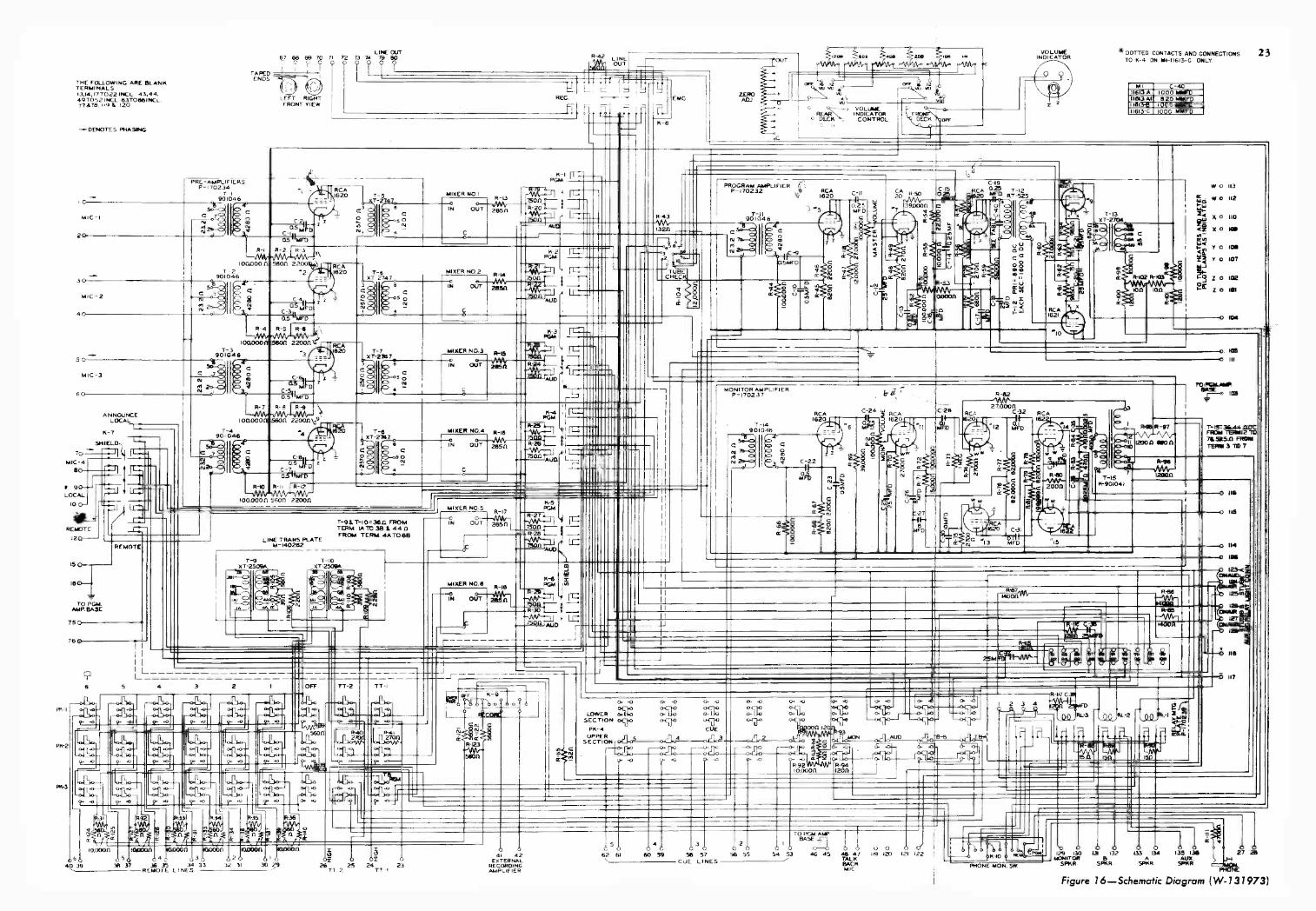
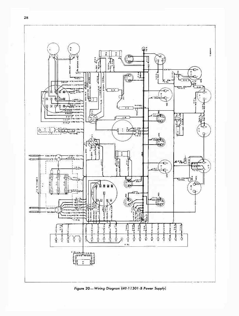
Figure 16 -Schematic Diagram (W-131973)
25
TYPES 76-B2 AND 76-B4 RCA CONSOLETTES
PART III
MI -11301-B Power Supply
TECHNICAL DATA
Power Required Power Supplied100 to 130 volts50 to 60 cycles225 watts
Fuses
a. D -C Plate Voltage (with respect to term. 17)Term.
No. Volts4 2855 220
Ma.42
4.6Transformer T-1: 2 amp. 6 REG 245 16Transformer T-2: 1 amp. 6 EMG 200 13Transformer T-3: I amp. 14 278 5.1
Tubes 15 210 1.216 375 62
1 RCA-5U4G Rectifier1 RCA -5Y3 GT/G Rectifier
Dimensions and WeightHeightWidthDepthDepthWeight
MountingWall or cabinet mounting
15 inches15 inches
8 inches15 Vs inches (opened )60 pounds
b. A -C Heater SupplyTerminals no. 1 and 2: 6.2 volts at 2.4 amp.Terminals no. 7 and 8: 6.2 volts at 0.3 amp.Terminals no. 9 and 10: 6.2 volts at i.6 amp.Terminals no. 12 and 13: 6.2 volts at 2.7 amp.
c. D -C Field SupplyTerminals no. 19 and 20: 100 ma to one, two, orthree, 100 -volt, 10 watt loudspeaker fields.
d. D -C Relay SupplyTerminals no. 17 and 18: 60 volts at 100 ma.
DESCRIPTION
The MI -11301-B Power Supply furnishes plate,heater and relay requirements for the RCA 76-Bseries of Consolettes. It also supplies loudspeakerfield power for a maximum of three 100 -volt, 10-
watt loudspeaker fields.
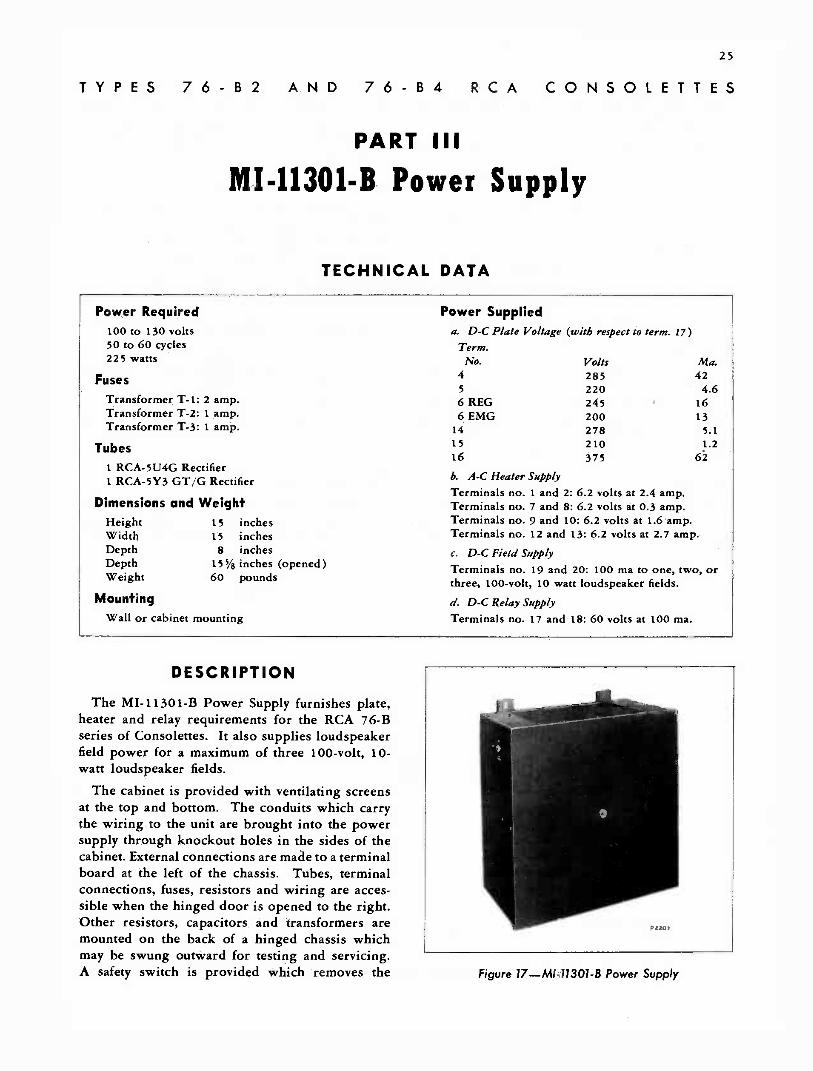
The cabinet is provided with ventilating screensat the top and bottom. The conduits which carrythe wiring to the unit are brought into the powersupply through knockout holes in the sides of thecabinet. External connections are made to a terminalboard at the left of the chassis. Tubes, terminalconnections, fuses, resistors and wiring are acces-sible when the hinged door is opened to the right.Other resistors, capacitors and transformers aremounted on the back of a hinged chassis whichmay be swung outward for testing and servicing.A safety switch is provided which removes the Figure 17-MI-113014 Power Supply
26
power from the circuit when the door is opened.A POWER ON -OFF toggle switch is mounted onthe side of the cabinet.
The power supply may be used to furnish powerfor any of the following equipment:
a. MI -11612 Consolette (Type 76-B).
b. MI -11613 Consolette (Type 76-B1).
c. MI -11613-A Consolette (Type 76-B2).
d. MI -11613-A1 Consolette (Type 76-B2).
e. MI -11613-B Consolette (Type 76-B2).
f. MI -11613-C Consolette (Type 76-B4).
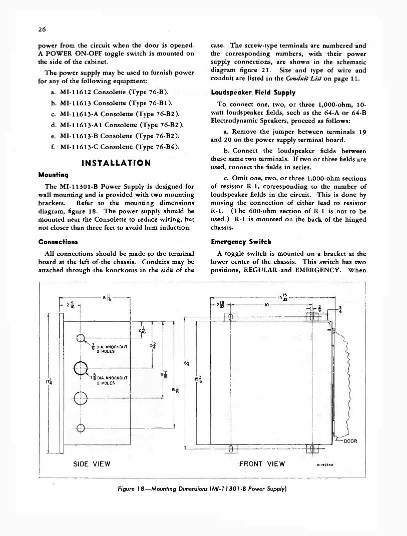
INSTALLATIONMounting
The MI -11301-B Power Supply is designed forwall mounting and is provided with two mountingbrackets. Refer to the mounting dimensionsdiagram, figure 18. The power supply should bemounted near the Consolette to reduce wiring, butnot closer than three feet to avoid hum induction.
Connections
All connections should be made to the terminalboard at the left of the chassis. Conduits may beattached through the knockouts in the side of the
case. The screw -type terminals are numbered andthe corresponding numbers, with their powersupply connections, are shown in the schematicdiagram figure 21. Size and type of wire andconduit are, listed in the Conduit List on page 11.
Loudspeaker Field Supply
To connect one, two, or three 1,000 -ohm, 10 -
watt loudspeaker fields, such as the 64-A or 64-BElectrodynamic Speakers, proceed as follows:
a. Remove the jumper between terminals 19and 20 on the power supply terminal board.
b. Connect the loudspeaker fields betweenthese same two terminals. If two or three fields areused, connect the fields in series.
c. Omit one, two, or three 1,000 -ohm sectionsof resistor R-1, corresponding to the number ofloudspeaker fields in the circuit. This is done bymoving the connection of either lead to resistorR-1. (The 600 -ohm section of R-1 is not to beused.) R-1 is mounted on the back of the hingedchassis.
Emergency Switch
A toggle switch is mounted on a bracket at thelower center of the chassis. This switch has twopositions, REGULAR and EMERGENCY. When
-2122
6*
I
SIDE VIEW
10
5-3215
1
FRONT VIEW M-140341
Figure 18-Mounting Dimensions (M1-11301-8 Power Supply)

27
the switch is thrown to the EMG position, themonitor amplifier power supply furnishes the powerfor the microphone preamplifiers and boosteramplifiers. The monitor amplifier is then used inplace of the program amplifier in the Consolette.
Hum Adjustment
If it becomes necessary to make a hum adjustmenton the Consolette, the following procedure isrecommended:
Load the microphone lines (nos. 1, 2, 3, and 4)with 250 -ohm resistors. Set the MASTER controland the mixer controls (1, 2, 3, and 4 attenuators )for 67 db or normal gain. Connect an amplifierhaving approximately 60 db gain to the LINE OUTterminals of the Consolette, then adjust the humpotentiometers P-1 and P-2 on the Power Supply,for minimum hum. (The LINE OUT switch mustbe set at the REG position and the associated mixerswitches on PROGRAM).
S-3 F- 1 F -2 T-1 C -13 R-7 C -7 T- 2 S -2
P-2
R-3
R-2
R-5
C-5
Figure 19-Interior View of Power Supply
RE
D/B
LKI
2
RE
D
RE
D,B
LY41
220
-HE
AS
3 4
-,
2 ID
AR
I B1_5
14 3
4.1,
.1
16
1 1T
IET
D C
HA
SS
IS
BR
OW
N
160R
BR
OW
NT
B/4
.4-B
RA
VO
LI,
BA
N13
1_
604
RE
DA
R-3
-2R
ED
BU
S.0
- R
ED
-T
B -
344,
r441
31_4
03.r
.2.
RE
D/E
ILN
BLU
ER
ED
/Ell
BLUE
$cp-
seow
if-
0,01
.4/1
,16i
a%,
EL
/OR
80-B
RO
W7N
-
111V
"''0
- E
R':
204.
RE
D -
S -
I-3
504
RV
:I-T
B-A
AA
404
RD
-L-
2-2
30A
BLA
C
204B
RIA
4BLI
'0.4
BIR
OW
NT
=i,
44,4
UR
N
4-...
.OR
N A
RE
D./
5-2-
2
SR
N /
BC
E
BLU
EB
RO
WN
2R
ED
3
RE
RE
D
TB
-3-
I52
RE
D
BR
ED
EIR
RIB
LA
L-4-
2R
ED
RE
D
B
T-1
1354
44

17 0 C tnI
3 a O co a 0 03 0 Z'
7-(9
0049
1-50
2) R
7-42
5-8
5R4-
GY
GR
EE
N
BLK
. RE
DT
R
.--R
ED
$BL BLK
GR
EE
N -
eRN
RE
D 8
,YE
L
BR
N,-
RE
D ii
YE
L.
TH
IS S
WIT
CH
OPE
RA
TE
D B
Y C
LO
SIN
G C
OV
ER
-3S
o0
N`o
R4
5001
1
V-1
C.Z
C -II
IOM
FD
IOM
F
6000
1000
0
1000
11
1000
11
R -
I
-L-
C.-
3IO
MF
D
R5
5 6
00 1
1
6800
11C
5
6
5600
.0.
IOM
FD
.
R2
1200
011
C4
10 M
FD
F 1
BLU
ER
ED
G.
YE
L.
2 A
MP
17-B
LuE
YE
LLO
W
900
75 5
-502
) X
7-2
5550
-D
125V
.411
5113
105V
. 2
F2.
!AM
P
.,4-q
3(9
0088
1-50
y X
T -
285
63
,4
0T
2C
>C
>
11, .
6
F 3
14A
4P
4D !GI
7
5Y3
GT
/G V-2
(27
1800
00
Iz I
L-2
L-3
111
111
$11
IR
T-4
42A
,X
T. 8
75.D
XT
-87
50(a
t 114
- 5
07)
(900
393-
501
C 9
1_ IS
IOC
625
MF
DC
7 10
MF
DC
8 IO
MF
D J
r T
25 M
FD
25 M
F 0
PI -
200
11
R 1
010
000/
1
P2-
200
ft
L-4
1111
R8
R5
0 22
-1
HIG
H A
.C.
1..0
21-I
0,20
1 S
PK
R F
LD.
0 17
-0 6 6
014
0 13
0 12
0 II
010
o 9
1-o
8
o-7
oiL
RE
G.
5-1
b 6
0 E
MG
.
o 5
XT
- 87
5 -
D47
001L
4700
(900
393-
501
)C
13 2
5 W
C,
C-T
MF
D
Cl2
8M
FD
0 4
o 3
M I
-113
01 -
BP
-174
552
O 0I
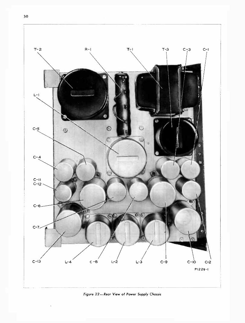
30
T-2 R-I T-I T-3 C-3 C-I
C-13 L-4 C -8
Figure 22-Rear View of Power Supply Chassis
P1229 -I
31
TYPES 76-B2 AND 76-B4 RCA CONSOLETTES
PART IV
Maintenance
TUBE CHECK READINGS
SelectorSwitchSetting Tube
MeterReading
SelectorSwitchSetting Tube
MeterReading
1 RCA -1620, preamplifier 6 RCA -1620, 1st stage ofnumber 1 70 ± 10 monitor amplifier 70 ± 10
2 RCA -1620, preamplifier 7 RCA -1620, 2nd stage ofnumber 2 70 ± 10 program amplifier 70 ±10
3 RCA -1620, preamplifier 8 RCA -1620, 3rd stage ofnumber 3 70 ± 10 program amplifier 70 ± 10
4 RCA -1620, preamplifier 9 RCA -1621, output stage ofnumber 4 70 ± 10 program amplifier 70 ± 10
5 RCA -1620, 1st stage of 10 RCA -1621, output stage ofprogram amplifier 70 ± 10 program amplifier 70 ± 10
INSPECTION AND CHECKINGParticular attention has been paid in the design
of the 76-B2 and 76-B4 Consolette to provide thebest facilities for reaching and servicing thecomponent parts. The lid of the Consolette ishinged so that the tubes are accessible for inspectingand servicing. It may be opened by turning thetwo spring catches through 90 degrees with a thincoin or small screwdriver. The upper section of thecabinet may also be raised to expose the terminalboards and other components.
For any piece of equipment that is subject tocontinuous use, as is most broadcast equipment, aregular routine of inspection should be set up andfollowed to avoid time off the air as a result of tubefailure, or noisy circuits caused by accumulation ofdirt on terminals and switches, corroded plugs, etc.It is advisable to carry one complete set of sparetubes in case of emergency.
The regular inspection should include checkingthe tubes. To check the tubes, first turn the VUCONTROL to the OFF position. The bias voltageof all tubes in the program channel may then bechecked by turning the TUBE CHECK switch to its
various positions and observing the VU meterreadings. The bias voltage provides an indicationof the flow of plate current, thereby giving anindication of the condition of the tubes. The normalmeter readings for the tubes are listed below.These readings were taken with an a -c line voltageof 115 volts, the power transformers of the MI -11301 -B Power Supply being connected for 115volt operation.
The tube socket and Radiotron cap contactsshould be cleaned with carbon tetrachloride orcrocus cloth every three months to insure noiselessoperation.
The mixer and MASTER control switch contactsshould be cleaned by applying Davenoil to thecontacts, rotating the knob, and, if any dark streaksappear, wiping off the contacts. Repeat this pro-cedure until absolutely clean, then lubricate with athin film of Davenoil. The Davenoil is included as apart of the equipment.
IMPORTANT: The Davenoil is provided forcleaning and lubricating the contacts of the mixersand volume controls and no other cleaning agent,such as carbon tetrachloride, should be used.

32
Care of Pushbutton Switches
Pushbutton switches of the 76-B2 (MI -11613-B)Consolette should be cleaned every four to sixmonths, or more often if dust and climatic condi-tions make it necessary. They should be cleaned asfollows, using the pushbutton cleaning kit suppliedwith the Consolette.
a. Turn off the power supply.
b. Open the panel and place a trouble lampbehind the switch that is to be cleaned first.
c. Pull the black pushbuttons from the switchesto be cleaned. The switch contacts will then be seenby looking into the plunger -rod hole with the aidof the trouble lamp.
d. Dip the brush into the special cleaninglubricant and drain off the excess.
e. Insert the brush into the plunger -rod holeand rub it over the contacts five or six times. Thenpush the plunger half way in to clear the contactsthat are normally covered by the contact springs andrepeat the process.
f. Push the plunger in and out several times towork the cleaning lubricant under the contactsprings.
g. Wipe the brush on a clean cloth and repeatd, e, and f.
h. Clean the remaining switches as directed ine, f, and g, and replace the pushbuttons.
Pushbutton switches of the 76-B4 Consolette(MI -11613-C) are of a different type than thoseused on the 76-B2. They should not require clean-ing under normal circumstances, but if noise isencountered as a result of dirty pushbutton con-tacts, they may be cleaned from the rear of thepanel as follows:
a. Remove the two screws at the extremes ofthe pushbuttons and pull the switch assembliesback from the panel without removing any of theconnecting wires.
b. Using a toothpick or similar object, apply adrop of Davenoil through each of the small eyeletholes directly over the switch contacts.
c. Work the plungers in and out and removethe excess oil from the switch assemblies.
d. Replace the switch assemblies.
Care of Key Switches on 76-B2 and 76-B4Canso!elites
As shipped from the factory, the various keyswitch contacts have been adjusted to give theproper sequence of circuit connections as they areoperated so that a microphone and speaker will notbe on at the same time in a studio and thus causeacoustic feedback. In case a replacement keyswitch is installed, or if feedback trouble is en-countered, the contacts should be adjusted using astandard key -switch or relay -contact bending tool.When adjusting the switches, the following desiredsequence of operation should be kept in mind: Therelay contacts must operate first and the audio circuitstransfer last. This is accomplished by relieving thetension of the center spring of the form D contactscontrolling the relays, and increasing the tensionof the center spring of the form D contacts carryingaudio. Care should be taken that the spring shapeis not altered, or the contact pressure reduced somuch as to cause poor contact or short circuits.To remove the key switch shield, it is only necessaryto remove the two screws in the contact "pile-ups"of the switches at the ends of the switches.
The loudspeaker cut off is accomplished withrelays and cannot be instantaneous. For quietoperation the key switches should be operatedsmoothly, not abruptly snapped into position.
Voltage Measurements
Tube voltages for the preamplifiers, programamplifier, and monitor amplifier are listed below.To obtain the values listed below, all except heatervoltages should be measured to ground using a d -cvoltmeter with a meter resistance of 5,000 ohmsper volt. Voltages listed are nominal and actualreadings should not vary more than about 5%from the given values.
NOTE: If the voltmeter used has a meter resistancegreater, or less than 5,000 ohms per volt, mostreadings taken will vary accordingly, the amount ofvariation depending upon the circuit in which themeter is used.
TUBE VOLTAGE TABLE
Preamplifier Voltages
Tube Element RCA -1620
Plate d -c 220Cathode d -c 8.3Heater d -c 6.2

33
TUBE VOLTAGE TABLE (CONT'D)Program Amplifier Voltages
Tube Element 1st RCA -1620 2nd RCA -1620 3rd RCA -1620 Each RCA -1621
Plate d -cScreen d -c
155 8070
85 270
Cathode d -c 6.0 1.9 2.2 23Heater a -c 6.2 6.2 6.2 6.2
Monitor Amplifier Voltages
Each RCA -1620Tube Element 1st RCA -1620 2nd RCA -1620 Phase Inverter Each RCA -1622
Plate d -c 155 115 140 340Screen d -c .... 220Cathode d -c 5.8 4.3 5.0 12Heater a -c 6.2 6.2 6.2 6.2
REPLACEMENT PARTS
The following list of parts is included to provideidentification when ordering replacement parts.Order from RCA Replacement Parts Department,Camden, New Jersey, giving the Stock Number andDescription of the parts wanted. Replacement partssupplied may be slightly different in form or sizefrom the original parts but will be completelyinterchangeable with them.
LIST OF PARTS
Symbol DescriptionStockNo,
MI -11301-B Power Supply
C-1, -2, -3, -4, Capacitor, 10 mf, 475 v 13224-5, -7, -8
C-6, -9, -10, -13 Capacitor, 25 mf, 475 v 13035C-11, -12 Capacitor, 8-8 mf, 450-450 v 17432F-1 Fuse, 2 amp. 3863F-2, -3 Fuse, 1 amp. 14133L-1 Reactor, RT-442-A 17568L-2, -3, -4 Reactor, XT -875-D 17569P-1, -2 Potentiometer, 200 ohms 18953R-1 Resistor, 600-1,000-1,000-
1,000 ohms 17167R-2, -3 Resistor, 12,000-6,800 ohms 51373R-4 Resistor, 500 ohms, 4.8 w 17451R-5, -6 Resistor, 5,600 ohms, 2 w 8087R-7 Resistor, 180,000 ohms, 2 w 19734R-8, -9 Resistor, 4,700 ohms, 2 w 17248R-10 Resistor, 10,000 ohms, 1 w 13097S-1 Switch, REG-EMG, toggle 7925
N
Z-0
°=c-)
CC
Figure 23-Relay Mounting Plate Wiring
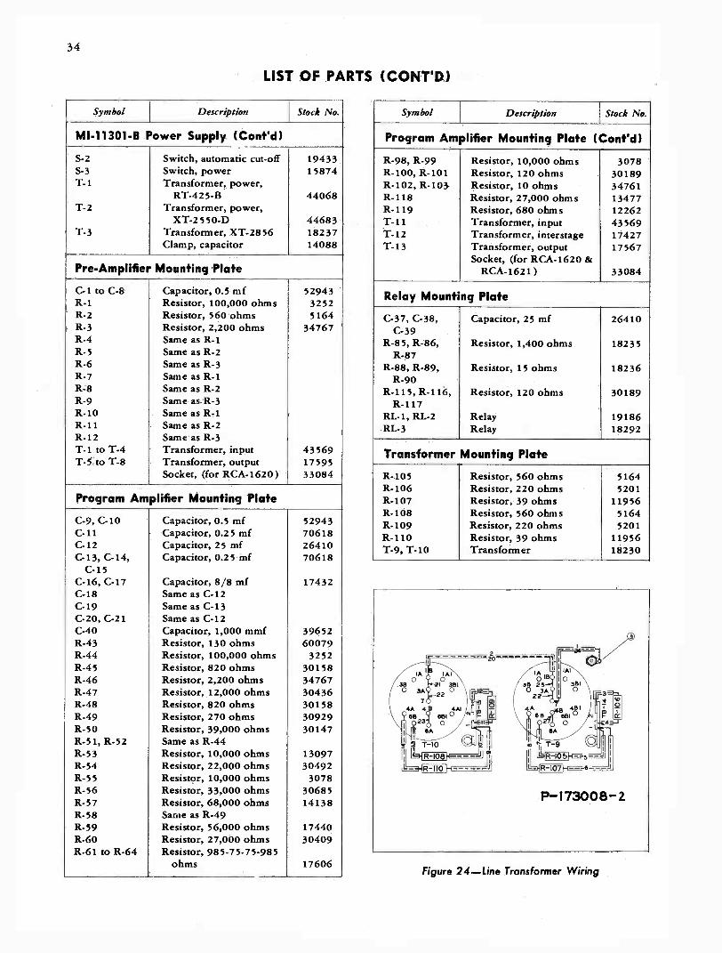
34
LIST OF PARTS (CONT'D)
Symbol Description Stock No.
MI -11301-B Power Supply (Cont'd)
S-2 Switch, automatic cut-off 19433S-3 Switch, power 15874T-1 Transformer, power,
RT-425-13 44068T-2 Transformer, power,
XT -2550-D 44683T-3 Transformer, XT -2856 18237
Clamp, capacitor 14088
Pre -Amplifier Mounting Plate
C-1 to C-8 Capacitor, 0.5 mf 52943R-1 Resistor, 100,000 ohms 3252R-2 Resistor, 560 ohms 5164R-3 Resistor, 2,200 ohms 34767R-4 Same as R-1R-5 Same as R-2R-6 Same as R-3R-7 Same as R-1R-8 Same as R-2R-9 Same as R-3R-10 Same as R-1R-11 Same as R-2R-12 Same as R-3T-1 to T-4 Transformer, input 43569T-5 to T-8 Transformer, output 17595
Socket, (for RCA -1620) 33084
Program Amplifier Mounting Plate
C-9, C-10 Capacitor, 0.5 mf 52943C-11 Capacitor, 0.25 mf 70618C-12 Capacitor, 25 mf 26410C-13, C-14, Capacitor, 0.25 mf 70618
C-15C-16, C-17 Capacitor, 8/8 mf 17432C-18 Same as C-12C-19 Same as C-13C-20, C-21 Same as C-12C-40 Capacitor, 1,000 mmf 39652R-43 Resistor, 130 ohms 60079R-44 Resistor, 100,000 ohms 3252R-45 Resistor, 820 ohms 30158R-46 Resistor, 2,200 ohms 34767R-47 Resistor, 12,000 ohms 30436R-48 Resistor, 820 ohms 30158R-49 Resistor, 270 ohms 30929R-50 Resistor, 39,000 ohms 30147R-51, R-52 Same as R-44R-53 Resistor, 10,000 ohms 13097R-54 Resistor, 22,000 ohms 30492R-55 Resistor, 10,000 ohms 3078R-56 Resistor, 33,000 ohms 30685R-57 Resistor, 68,000 ohms 14138R-58 Same as R-49R-59 Resistor, 56,000 ohms 17440R-60 Resistor, 27,000 ohms 30409R-61 to R-64 Resistor, 985-75-75-985
ohms 17606
Symbol Description Stock No.
Program Amplifier Mounting Plate (Cant's()
R-98, R-99 Resistor, 10,000 ohms 3078R-100, R-101 Resistor, 120 ohms 30189R-102, R-103 Resistor, 10 ohms 34761R-118 Resistor, 27,000 ohms 13477R-119 Resistor, 680 ohms 12262T-11 Transformer, input 43569T-12 Transformer, interstage 17427T -I3 Transformer, output 17567
Socket, (for RCA -1620 &RCA -1621) 33084
Relay Mount ng Plate
C-37, C-38, Capacitor, 25 mf 26410C-39
R-85, R-86, Resistor, 1,400 ohms 18235R-87
R-88, R-89, Resistor, 15 ohms 18236R-90
R-115, R-116, Resistor, 120 ohms 30189R-117
RL-1, RL-2 Relay 19186RL-3 Relay 18292
Transformer Mounting Plate
R-105 Resistor, 560 ohms 5164R-106 Resistor, 220 ohms 5201R-107 Resistor, 39 ohms 11956R-108 Resistor, 560 ohms 5164R-109 Resistor, 220 ohms 5201R-110 Resistor, 39 ohms 11956T-9, T-10 Transformer 18230
Figure 24-Line Transformer Wiring
3 0 Z.
BR
26 B
RN
i0 B
LK
21Y
EL
TB
22
XT
-28
75
0 O
D C T-5
0R
.-1
T-3
635,
2
XT
-287
5
()C
T-28
78
®C
* 0
* ®
T-6
T-
7
49 R
ED
RE
D
\30 B
RN
II B
LK
r22Y
EL
IBLK
®®
1-62
®
\N.X
2.-3
635
32 E
RN
ss 1
2 B
LK
23 Y
EL
2 B
LKos
6s T-3 -363
5
()--
(T-2
878
T-
B
47 R
ED
334
BR
N
c 13
BLK
124Y
EL
Z\
3 B
LK
03 4.1 T
$-19
t35 I T
B -
20
®®
T-
4
T-3
635
G-1
TB
24
4 E
LKN
OT
E -
TW
IST
TH
E F
OLL
OW
ING
PA
IRS
-2
8& 2
9, 3
0 &
3432
&33
& 3
4 8.
35.
T-
le 2
987
-G
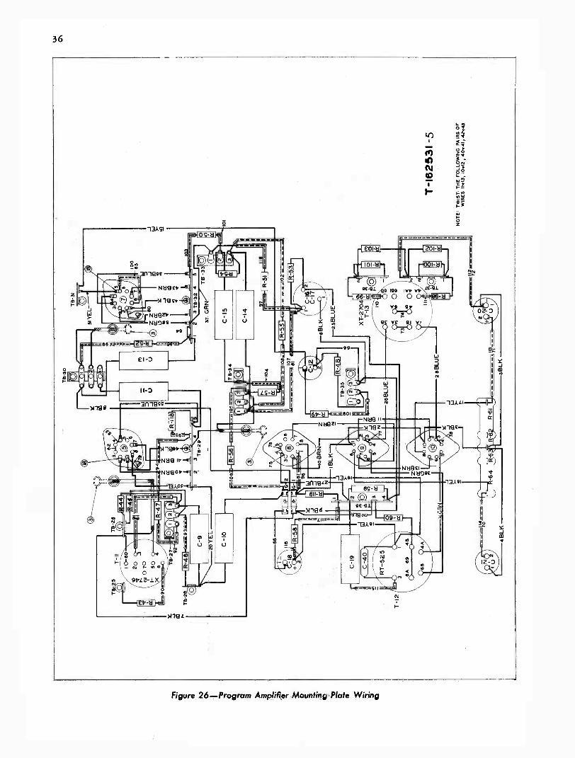
36
.go
13ASI
a
co
>A 19 L
O
N
-- N'164-11
marl
99
e
P.2
N139
12z
0
r
NoeciNO DOE
Figure 26-Program Amplifier Mounting Plate Wiring

CU
TB
-6
22YEL
-J >O N-
C-3
2
R-7
8
6 0-
.-35
BR
IN
R -
80
8-1
2
NI 3
U
cr,
TB
-7
OC t 3
C
C-
31
C
36 B
RN
'--37
BR
N
32
C -
28
BR
N
IJ _J 03 N TB
8
99
G -
I
24 Y
EL
100
C-2
3
C-2
292
C-2
4
Olt.
.6le
siY
EL
10
010
60
00
25
03 2
TB
-12
TB
-13
NO
TE A
LL H
EA
TE
R L
EA
DS
, PA
IRS
-55
8. 5
6,57
6.58
,361
37,3
3 83
4,30
131,
32
& 3
5 T
O B
E T
WIS
TE
D.
XT
-3
635
T-1
6299
0-6

38
LIST OF PARTS (CONT'D)
Symbol Description Stock No.
Monitor Amplifier Mounting Plate
C-22, C-23 Capacitor, 0.5 mf 52943C-24 Capacitor, 0.25 mf 70639C-25 Capacitor, 25 mf 26410C-26, C-27 Capacitor, 8/8 mf 17432C-28 Capacitor, 0.1 mf 70638C-30 Capacitor, 10 mf 13222C-31, C-32 Same as C-28C-34 Same as C-25C-35, C-36 Capacitor, 0.0025 mf 70644R-66 Resistor, 100,000 ohms 3252R-67 Resistor, 2,200 ohms 34767R-68 Resistor, 820 ohms 30158R-69 Resistor, 39,000 ohms 30434R-70 Resistor, 2,700 ohms 30730R-71 Resistor, 15,000 ohms 36714R-72 Resistor, 100,000 ohms 3252R-73 Resistor, 1 megohm 30652R-74, R-75 Resistor, 2,700 ohms 30730R-76, R-77 Resistor, 82,000 ohms 8064R-78 Resistor, 100,000 ohms 3252R-79 Resistor, 8,200 ohms 14250R-80 Resistor, 200 ohms 30287R-81 Resistor, 100,000 ohms 3252R-82 Resistor, 27,000 ohms 30409R-83, R-84 Resistor, 470 ohms 30681.R-95, R-96 Resistor, 1,200 ohms 30731R-97 Resistor, 680 ohms 12262T-14 Transformer, input 43569T-15 Transformer, output 43679
Socket, (for RCA -1620 &RCA -1622) 33084
Front Panel Assembly
J-1 Jack, phones 16999K-i to K-3 Switch key, A -P #1 to #3 18290K-4 Switch key, A -P #4
(MI -11613-B only) 18290K-4 Switch key, A -P #4
(MI -11613-C only) 53431K-5, K-6 Switch, key, A -P #5, #6 17910K-7 Switch, key, "Announce" 19432K-s Switch, key, "Line Out" 18291K-9, K-10 Switch lever, "Override -
Off -Record,""Phone -Mon" 19573
PK-1 Switch, pushbutton #1(9 Keys) 18317
PK-2 Switch, pushbutton #2(9 Keys) 18318
PK-3 Switch, pushbutton #3(9 Keys) 19572
PK-4 Switch, pushbutton #4(9 Keys) 18320
Symbol Description Stock No.
Front Panel Assembly (Coale!)
R-13 to R-18 Resistor, 270 ohms (atMixer 1-6 Resp.) 54264
R-19 to R-30 Resistor, 750 ohms (atSwitch K-i to K-6) 19785
R-31 to R-36 Resistor, 560 ohms (atSwitch K-8, K9; PK-1to PK-3) 5164
R-38, R-39 Same as R-31R-40, R-41 Resistor, 270 ohms
(at PK-2) 30929R-42 Same as R-31R-65 Resistor, 132 ohms
(at Switch K-6) 60079R-91, R-92 Resistor, 10,000 ohms,
1/2 W. 3078R-93, R-94 Resistor, 120 ohms,
1/2 W. 30189R-104 Resistor, 12,000 ohms
(at Tube Check) 30436R-111 Resistor, 4,700 ohms
(at Jack J-1) 30494R-113, R-114 Resistor, 10 ohms, 1/2 W. 34761R -I21, R-122 Resistor, 5,600 ohms
(at Switch K-9) 30734R-123 Same as R-31R-124, R-125 Resistor, 10,000 ohms
(at PK-3) 3078R-127, R-128, Same as R-124R-130, R-131,R-133, R-134,R-136, R-137,R-139, R-140
Attenuator, (#1 to #6) 17644Attenuator, master 17643Attenuator, monitor 17604Handle 54532Knob, for Attenuators
#1 to #8 17269Knob, for Tube Check or
VI Switches 17268Knob, for K-9 and K-10 54534Lubricant, for push
button switches 44275Meter, VU and Tube
Check 43186Oil, attenuator oil 20752Pad, multiple pad
(7100/3900 ohms) 19328Pad, zero adjusting
network (800 ohms) 19327Switch, tube -check 19571Switch, VI control 19570

1.
J -I 0
I4259
4 uE . 199 279
Z2. 299
319
92.6 339 r 410 [[42 499 050 579 958 859 1[66
928 389 036 439 944 519 952 599 960 679 968
930 379 93B 459 946 539 954 619 [162 699 970
932 399 040 479 940 559 [156 639 [164 719 972
Nil 16 924 31 932 399 940 479 948 559 956 630 964 719 972
13 I 21 379 938 459 946 539 054 619 962 61 70
0 279 8 359 036 439 944 519 952 599 [160 6711 968
2 99 910 179 91111.1 926 339 034 410 042 499 950 570 1158 659
AL/D. MON.
713-A
90 019 1911
920290 030
70 DB 170, 018 279 028 37
59 06 j841 2 259
30 04Il
019. 230
ID 02 II[ 912 21
2 3 4 5 6
20t- a0
oa a0
M1 -11613-C IS SAME AS MI -11613-13, EXCEPTFOR DOTTED CONNECTION ON K-4
TT- I TT -2 OFF
1
K-8
2 3 4 5 6
91430 1 712 ao 7Q 46 630Tl
H2 211 r o3.3 450 146 9311 164 610 162 .9p fro
912I 920 291 1129 036
1 944 911 062 I 066 6 066
39
ID119 I8 250 330 034 419 942 490 frio 570
flea t
I L -1-1W6914 129 IF; 2J36 379 jIF'N 11 "
4 3
tD4 1 OM LI20 920 2 958 r1 92 11 OM 1 1
026 3311 1134 1142
iki-J/-i-
7
67
990 It 098 -an
W-191869
a
Figure 28-Front Panel Wiring (W-131969)
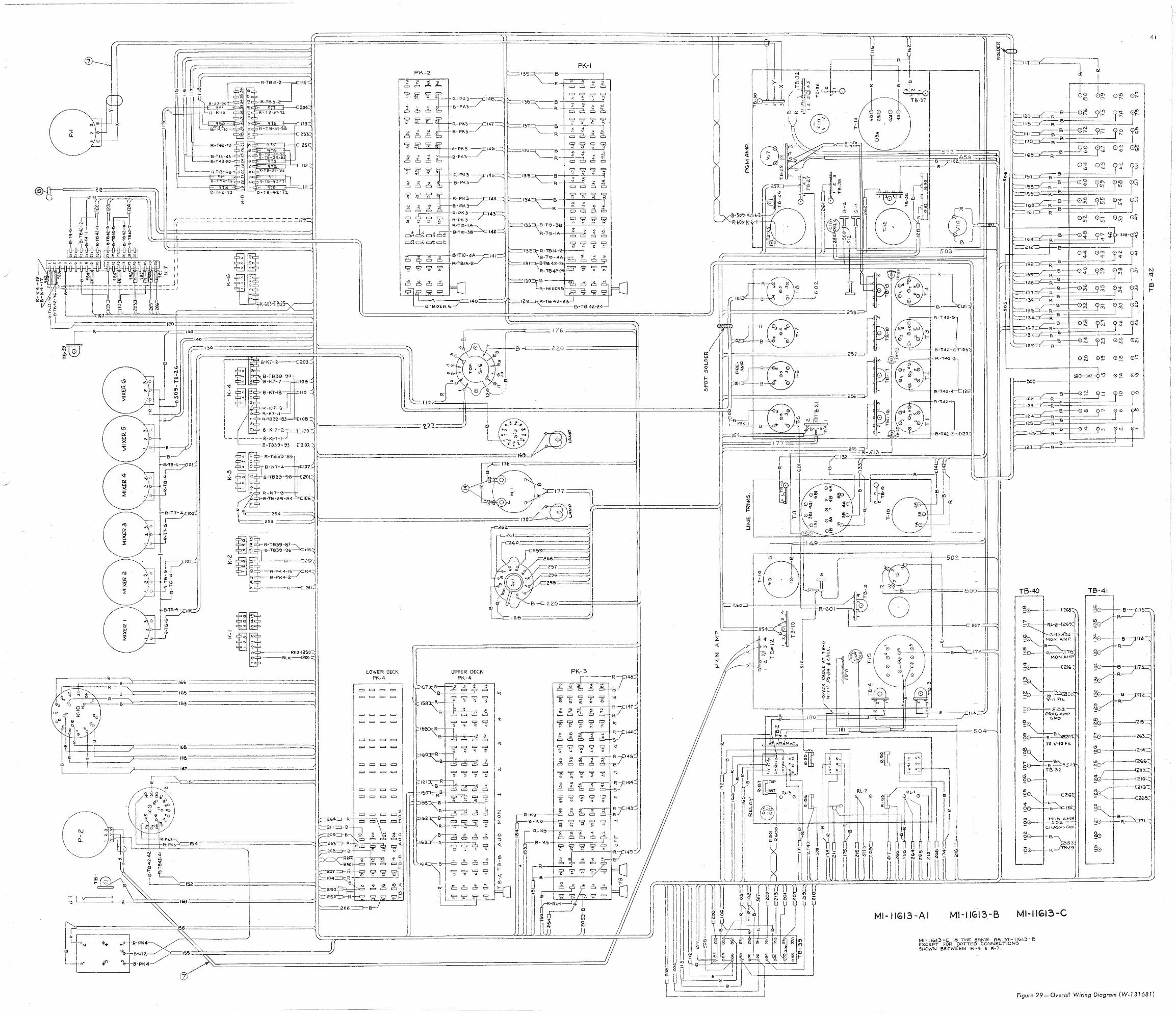
1
41
-
rf
0.,17--2123rr
rr.2
111-35 ; ei1 1 1 1 1III! RRP
-003-7E,25-)
120
lY
e -K7 -16-C20
B -T1339-913-167-7
6-10-113
10.335-23
10
PK-2
o
.5' .7T iF
Y A A - P"
Ia "a A
.R.P.K1,3144=2,
.11
=Doe tot =02
1=-105PK-I
a aT T
ea IA O
e. 2, 1 ;68.88W.=1, A
ado a--=rsam, 1. 7 7 7 7
A
7 q 7 7
.--132B.01014215.1.10.s 24B14,-. A
14 4 4- 4,
cl 'A A A A Aw
B TB 4224
B4642-260-7642-25
7.
119
176
220
O
tiB
' C
5-5045201-'03-I46 -I
A
TB -32
_852
B
503
255
0O ,40
5-K-2-2 Tr -CM:11-12-7-1-J
1-1239-93 C202.2
21-1239-139
6 B2-4 CP?.
20/
1340-39 B4
2535_
r X19-
**
237
21,039-117-,10,030 -06--,C.052
111-C202`
Dc1042
/2-225if.
-1120<25012,0.-120012
222
LOWER DECK90.4
1=1 0 0 01261 0 1=
0 1= 00 0 0 0P 0 0 00 0 0 0
UPPER DECKPR.4
169
201
250205
257
5i.2215-
220
lee
PK-3
02460113/1-
0
"
B 1216
R-44242
B6;
61612-4-"126,
6422-2--C1272
0-
o,
180
21-601- 0
501
250
O
rep L
III
MI -11613 -AI
504
a 8:,=115=' R
s-111-1/ R 15-C)F 96- 113
ol0'7 0:
:-.= 1512.=e -B a °2 9E; Trz
4. e'
1-=.049 OIL911's_Qlnr
10E1 07, op,
2,4715---01 90; *0-02.1V
Da 0,411
-152 B
:=159--8 4 9$-12412"'
B 0:4
-107 ?'_32
CM 912
4;4
1 r5,fg r
rfg r
C'71 92
02 02 02 et
- 500
e-er2
7=t04F78----°0
031 0;
620-007-00 2,1 00
12 T
m
15-40
MI -11613-B MI -11613-C
sNowN BETWEEN -4 f 7.
13-41
Figure 29 -Overall Wiring Diagram (W-131681)