rückenbreite bis 10 mm (1 blatt = 0,106 mm für xbs) · pdf filearticle no.: xxxxxx...
TRANSCRIPT

Moeller GmbHIndustrieautomationHein-Moeller-Straße 7–11D-53115 Bonn
E-Mail: [email protected]: www.moeller.net
© 2002 by Moeller GmbHSubject to alterationAWB2528-1427GB DMD/DMD 10/04Printed in the Federal Republic of Germany (11/02)Article No.: xxxxxx
Rü
ckentext
A AThink future. Switch to green. Think future. Switch to green.
Building Automation SystemsIndustrial Automation
User Manual
10/04 AWB2528-1427GB
EASY222-DNDeviceNet Slave Interface
A
Rückenbreite bis 10 mm (1 Blatt = 0,106 mm für XBS)

All brand and product names are trademarks or registered trademarks of the owner concerned.
1st published 2002, edition date 08/022nd edition 10/04See revision protocol in the “About this manual“ chapter
© Moeller GmbH, 53105 Bonn
Author: Ronny HappEditor: Thomas KrachtTranslator: David Long
All rights reserved, including those of the translation.
No part of this manual may be reproduced in any form (printed, photocopy, microfilm or any otherprocess) or processed, duplicated or distributed by means of electronic systems without written permission of Moeller GmbH, Bonn.
Subject to alteration without notice.
Rückenbreite festlegen! (1 Blatt = 0,106 mm)

Moe
llerG
mbH
Safe
ty in
stru
ctio
nsWarning!Dangerous electrical voltage!
I
Before commencing the installation
• Disconnect the power supply of the device.
• Ensure that devices cannot be accidentally restarted.
• Verify isolation from the supply.
• Earth and short circuit.
• Cover or enclose neighbouring units that are live.
• Follow the engineering instructions (AWA) of the device concerned.
• Only suitably qualified personnel in accordance with EN 50110-1/-2 (VDE 0105 Part 100) may work on this device/system.
• Before installation and before touching the device ensure that you are free of electrostatic charge.
• The functional earth (FE) must be connected to the protective earth (PE) or to the potential equalisation. The system installer is responsible for implementing this connection.
• Connecting cables and signal lines should be installed so that inductive or capacitive interference does not impair the automation functions.
• Install automation devices and related operating elements in such a way that they are well protected against unintentional operation.
• Suitable safety hardware and software measures should be implemented for the I/O interface so that a line or wire breakage on the signal side does not result in undefined states in the automation devices.
• Ensure a reliable electrical isolation of the low voltage for the 24 volt supply. Only use power supply units complying with IEC 60364-4-41 (VDE 0100 Part 410) or HD 384.4.41 S2.
• Deviations of the mains voltage from the rated value must not exceed the tolerance limits given in the specifications, otherwise this may cause malfunction and dangerous operation.
• Emergency stop devices complying with IEC/EN 60204-1 must be effective in all operating modes of the automation devices. Unlatching the emergency-stop devices must not cause restart.
• Devices that are designed for mounting in housings or control cabinets must only be operated and controlled after they have been installed with the housing closed. Desktop or portable units must only be operated and controlled in enclosed housings.

II
• Measures should be taken to ensure the proper restart of programs interrupted after a voltage dip or failure. This should not cause dangerous operating states even for a short time. If necessary, emergency-stop devices should be implemented.
• Wherever faults in the automation system may cause damage to persons or property, external measures must be implemented to ensure a safe operating state in the event of a fault or malfunction (for example, by means of separate limit switches, mechanical interlocks etc.).
10/04 AWB2528-1427GB
1
Contents
About this manual 7List of revisions 7Target group 7Further manuals for this device 7References 8Device name 8Abbreviations and symbols 10Writing conventions 10
1 The EASY222-DN 11System overview 12Structure of the unit 13EASY222-DN Communication profile 14Hardware and operating system requirements 15Use other than intended 16
2 Installation 17EASY222-DN connection to the basic unit 17Connecting the power supply 18Connecting DeviceNet 19– Pin assignment DeviceNet 19– Terminating resistors 20EMC compatible wiring 20Potential isolation 21Data transfer rates – automatic baud rate recognition 22– Maximum distances and bus cable lengths 22

Contents
2
10/04 AWB2528-1427GB
3 Operating the device 23Initial power on 23DeviceNet setting the slave address 24– Setting the address by means of EASY-SOFT 26– Setting the address via the master PLC 26LED status displays 27– Module status LED 27– Network status LED 28Cycle time of the "easy" basic unit 29EDS file 29
4 DeviceNet functions 31Object model 31– Identity Object 35– DeviceNet object 37– easy Object 38DeviceNet Communication profile 41– I/O Messages 41– Explicit Messages 42
5 Direct data exchange with easy/MFD (Polled I/O Connection) 47Input data:Mode, S1 – S8 49Output data:mode, R1 – R16 51

Contents10/04 AWB2528-1427GB
3
6 Control Commands for easy600 55Read and write date and time,summer and winter time 57Read image data 61– General notes on working with image data 61– Overview 61– Digital inputs, P buttons and operating buttons 62– Analog inputs: I7 – I8 65– Timing relays, counter relays, timer switch,
analog value comparator 66– Auxiliary relay (marker), digital outputs, text
display 69Read/write function blocks 72– Overview 72– Analog value comparator A1 – A8: write
actual values (function, comparison values) 73– Counter relays C1 – C8: read actual value 76– Counter relay C1 – C8: write reference value 78– Counter relay C1 – C8: read reference value 80– Timing relays T1 – T8: read actual value
(timing range, actual value, switching function) 82– Timing relays T1 – T8: write parameters
(timing range, reference value, switching function) 86
– Switching timer Ö1 – Ö4: read actual value (channel, ON time, OFF time) 90
– Switching timer Ö1 – Ö4: read setpoint value (channel, ON time, OFF time) 94

4
10/04 AWB2528-1427GB
7 Control commands for easy700 99Read/write date and time 101Read/write image data 105– Overview 105– Analog value comparators/threshold comparators:
A1 – A16 106– Counters: C1 – C16 107– Text function blocks: D1 – D16 108– Local inputs: I1 – I16 109– Local analog inputs: IA1 – IA4 110– Write marker: M1 – M16/N1 – N16 112– Read marker: M1 – M16/N1 – N16 114– Operating hours counters: O1 – O4 116– Local P buttons: P1 – P4 117– Local outputs: Q1 – Q8 119– Inputs/outputs of EASY-LINK:
R1 – R16/S1 – S8 120– Timers: T1 – T16 122– Year time switch: Y1 – Y8 123– Master reset: Z1 – Z3 124– 7-day time switch: ö1 – ö8 125Read/write function block data 126– General notes 126– Overview 126– Analog value comparator/threshold comparator:
A1 – A16 127– Counter relays: C1 – C16 130– Operating hours counters: O1 – O4 133– Timing relays: T1 – T16 135– Year time switch: Y1 – Y8 138– 7-day time switch: Ö1 – Ö8 141Analysis – error codes via EASY-LINK 144

Contents10/04 AWB2528-1427GB
5
8 easy800/MFD Control Commands 145Version history 147Read/write date and time 148– Winter/summer time, DST 149Read/write image data 154– Overview 154– Local analog inputs: IA1 – IA4 155– Local diagnostics: ID1 – ID16 157– Read local inputs: IW0 159– Inputs of the network station: IW1 – IW8 161– Marker: M.. 162– Local P buttons: P1 – P4 165– Local analog output: QA1 167– Local outputs: QW0/
outputs of the network station: QW1 – QW8 168– Inputs/outputs of EASY-LINK: RW/SW 170– Receive data network: RN1 – RN32/
Send data network: SN1 – SN32 172Read/write function block data 174– General notes 174– Overview 175– Analog value comparator: A01 – A32 176– Arithmetic function block: AR01 – AR32 178– Block Compare: BC01 – BC32 180– Block Transfer: BT01 – BT32 182– Boolean operation: BV01 – BV32 184– Counter: C01 – C32 186– Frequency counters: CF01 – CF04 188– High-speed counter: CH01 – CH04 190– Incremental encoder counters: CI01 – CI02 192– Comparator: CP01 – CP32 194– Text output function block: D01 – D32 196– Data block: DB01 – DB32 199– PID controller: DC01 – DC32 201– Signal smoothing filter: FT01 – FT32 204– Receipt of network data: GT01 – GT32 206– 7-day time switch: HW01 – HW32 208– Year time switch: HY01 – HY32 211– Value scaling: LS01 – LS32 214– Master reset: MR01 – MR32 216

Contents
6
10/04 AWB2528-1427GB
– Numerical converter: NC01 – NC32 218– Hours-run meters: OT01 – OT04 220– Sending of network data: PT01 – PT32 222– Pulse width modulation: PW01 – PW02 224– Synchronize clock function block: SC01 226– Set cycle time function block: ST01 227– Timing relays: T01 – T32 229– Value limitation: VC01 – VC32 232Analysis – error codes via EASY-LINK 234
9 What happens if...? 237
Annex 239Technical Data 239Dimensions 242EDS file 243
Glossary 247
Index 255

10/04 AWB2528-1427GB
7
About this manual
List of revisions The following amendments have been made since the last edition:
Target group This manual is targeted at automation technicians and engineers. Expert knowledge of the DeviceNet fieldbus and programming of a DeviceNet master PLC is assumed. Furthermore, you should be familiar with the handling of the easy control relay and the MFD HMI control.
Further manuals for this device
The following manuals apply:
• “easy412, easy600 control relays” (AWB2528-1304-GB)• “easy700 control relay” (AWB2528-1508GB)• “easy800 control relay” (AWB2528-1423GB)• “MFD-Titan HMI control” (AWB2528-1480GB).
All manuals are available on the Internet for download as PDF files. Enter the document number at http://www.moeller.net/support: as a search term in order to quickly locate the required manual.
Edition Page Subject New
10/04 General easy700/800/MFD j

About this manual
8
10/04 AWB2528-1427GB
References [1]DeviceNet Specification Volume IRelease 2.0, Errata 1 - 4April 1, 2001
[2]DeviceNet Specification Volume IIRelease 2.0, Errata 1 - 4April 1, 2001
Device name The following short names for equipment types are used in this manual, as far as the description applies to all of these types:
• easy412 for EASY412-..-... devices• easy500 for
– EASY512-AB...– EASY512-AC– EASY521-DA… – EASY512-DC
• easy600 for– EASY6..-AC-RC(X)– EASY6..-DC-.C(X)
• easy700 for– EASY719-AB…– EASY719-AC…– EASY719-DA…– EASY719-DC…– EASY721-DC…
• easy800 for– EASY819-...– EASY820-...– EASY821-...– EASY822-...

Device name10/04 AWB2528-1427GB
9
• MFD-CP8.. for– MFD-CP8-ME– MFD-CP8-NT
• easy-AB for– EASY512-AB...– EASY719-AB...
• easy-AC for– EASY412-AC-..– EASY512-AC-..– EASY6..-AC-RC(X),– EASY719AC– EASY8..-AC-...
• easy-DC for– EASY412-DC-..– EASY512-DC-..– EASY6..-DC-…– EASY719-DC-..– EASY8..-.DC-...
• easy-DA for– EASY412-DA...– EASY512-DA...
• EASY719-DA...

About this manual
10
10/04 AWB2528-1427GB
Abbreviations and symbols
Meaning of abbreviations and symbols used in this manual:
Writing conventions For greater clarity, the name of the current chapter is shown in the header of the left-hand page and the name of the current section in the header of the right-hand page. Pages at the start of a chapter and empty pages at the end of a chapter are exceptions.
X indicates actions to be taken.
BCD Binary Coded Decimal code
CAN Controller Area Network
DEC Decimal (number system based on 10s)
HEX Hexadecimal (Number system based on 16)
MAC ID Media Access Control Identifier
ODVA Open DeviceNet Vendor Association
PC Personal Computer
SELV Safety Extra Low Voltage“
UCMM Unconnected Message Manager
h Note!Warns of a hazardous situation that could result in damage to the product or components.
i Caution!Warns of the risk of major damage to assets and minor injury.
j WarningWarns of the possibility of a hazardous situation that could result in major damage and serious or fatal injury or even death.
h Draws your attention to interesting tips and supplementary information

1
10/04 AWB2528-1427GB
1
1 The EASY222-DN
The EASY222-DN communication module has been developed for automation tasks with the DeviceNet field bus. EASY222-DN acts as a “gateway” and can only be operated in conjunction with the expanded easy600, easy700, easy800 or MFD basic units. The system unit consists of the easy/MFD control device and the EASY222-DN DeviceNet gateway and operates exclusively as a slave station on the fieldbus system.
The EASY222-DN
12
10/04 AWB2528-1427GB
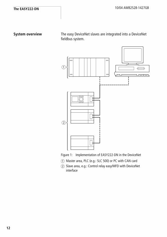
System overview The easy DeviceNet slaves are integrated into a DeviceNet fieldbus system.
Figure 1: Implementation of EASY222-DN in the DeviceNet
a Master area, PLC (e.g.: SLC 500) or PC with CAN cardb Slave area, e.g.: Control relay easy/MFD with DeviceNet
interface
a
b

Structure of the unit
3
10/04 AWB2528-1427GB
1
Structure of the unit
Figure 2: Structure of EASY222-DN
a EASY-LINK socketb 5-pin DeviceNet connection to ODVAc Power supply 24 V d Equipment rating platee Network Status LED NSf Module Status LED MS
MS
NS
a
b
d
ef
c

The EASY222-DN
14
10/04 AWB2528-1427GB
EASY222-DN Communication profile
• Predefined master/slave communication settings– The I/O polling connection is used for the transfer of
3 bytes of input data (R1 to R16) and 3 bytes of output data (S1 to S8) between the easy base unit with gateway interconnection and the DeviceNet PLC.
– The I/O Change of State/Cyclic connection (acknowledged, unacknowledged) is used to transfer 2 bytes of diagnostic data from the easy control relay to DeviceNet the PLC.
– The explicit connection set-up is used for read/write access to function relay parameters in the easy control relay. This type of connection set-up also supports the configuration, diagnostics and management services of the control relay.
• DeviceNet Communication adapter profile (device type 12), which has been expanded by easy requests
• Group 2 server• UCMM-capable device• Dynamic set-up of explicit and I/O connections are
possible • Device Heartbeat Message• Device Shutdown Message• Offline communication settings

Hardware and operating system requirements
5
10/04 AWB2528-1427GB
1
Hardware and operating system requirements
The EASY221-DN expansion unit operates together with the easy600, easy700, easy800 and MFD basic units from the following operating systems:
Basic unit EASY221-DN expansion unit
Device version OS version Device version = 01 Device version f 02
easy600
f 04 from 2.4 x x
easy700
f 01 from 1.01.xxx – x
easy800
f 04 from 1.10.xxx – x
MFD-CP8..
f 01 from 1.10.xxx – x
The device version of the respective basic or expansion unit is stated on the right-hand side of the enclosure. Example: EASY221-DN: 02-206xxxxxxx (02 = device version)The operating system version (OS) of the respective basic device can be read via the EASY-SOFT. On the easy700, easy800 and MFD-CP8.. devices it is possible to read out the information directly on the device. Refer to the respective manual for information.An overview of the modifications and innovations with the different device versions of the easy800 can be found on page 147.

The EASY222-DN
16
10/04 AWB2528-1427GB
Use other than intended "easy" may not be used to replace safety-relevant control circuits, e.g.:
• Furnace,• emergency-stop,• crane or• Two-hand safety controls.

7
10/04 AWB2528-1427GB
1
2 Installation
Applicable are the same guidelines as for easy/MFD basic units with expansion modules.
EASY222-DN connection to the basic unit
Figure 3: Mounting the EASY222-DN on the basic unit
+ Installation + Removal
1
3
4
2
1 2
3 4

Installation
18
10/04 AWB2528-1427GB
Figure 4: Connection between basic unit and EASY222-DN
Connecting the power supply
EASY222-DN operates with a 24 VDC supply voltage (a section “Power supply”, page 241).
Figure 5: Power supply of EASY222-DN
EASY-LINK
EASY619-...EASY621-...EASY7..EASY8..MFD-CP8..
EASY222-DN
j WarningAlways ensure safe electrical isolation between the extra low voltage (SELV) and the 24-V power supply.
+24 V
> 1 A
0 V
+24 V 0 V

Connecting DeviceNet
9
10/04 AWB2528-1427GB
1
Connecting DeviceNet A 5-pole DeviceNet plug connects the DeviceNet interface of thedevice to the DeviceNet fieldbus.
Please use a special DeviceNet plug and DeviceNet cable for this connection. Both are specified in the ODVA. The type of cable has an influence on the maximum available length of the bus line and thus on the data transfer rate.
Pin assignment DeviceNet
Figure 6: Pin assignment of the equipment socket
1 GND black2 CAN_L blue3 screen clear4 CAN_H white5 24 V red
All pins of the plug must be connected to ensure safe communication of the EASY222-DN on the fieldbus DeviceNet. This also applies to the 24-V bus voltage.
1
2
3
4
5
1
2
3
4
5
V–
CAN_L
Shield
CAN_H
V+ (24 V)
h The gateway therefore does not participate in communication on the bus if the bus voltage is not available. The Network status LED indicates OFF mode in this situation.

Installation
20
10/04 AWB2528-1427GB
Terminating resistors
The first and last node of a DeviceNet network must be terminated by means of a 120 O bus termination resistor. This device is interconnected between the CAN_H and CAN_L terminals.
Figure 7: Terminating resistors RT: CAN_H and CAN_L terminals
RT = 120 O
EMC compatible wiring Electromagnetic interference may lead to unwanted effects on the communications fieldbus. which can be significantly reduced by using the cable described above, a shielded RJ45 connector and by terminating the screen.
The two figures below show the correct termination of the shielding.
Figure 8: Shielding connection to the mounting rail
0 1 n . . .
RTRT
M4
ZB4-102-KS1
FM 4/TS 35(Weidmüller)
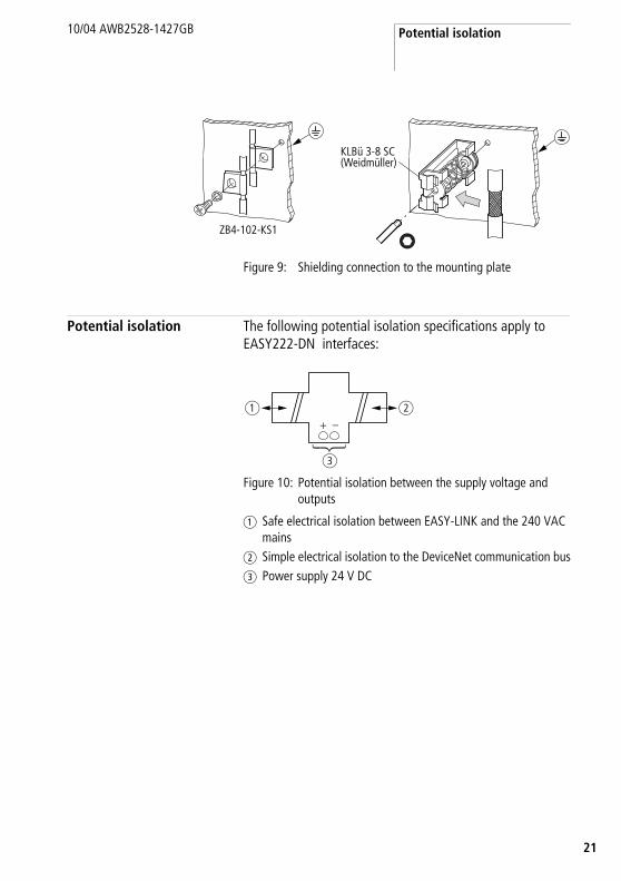
Potential isolation
1
10/04 AWB2528-1427GB
2
Figure 9: Shielding connection to the mounting plate
Potential isolation The following potential isolation specifications apply to EASY222-DN interfaces:
Figure 10: Potential isolation between the supply voltage and outputs
a Safe electrical isolation between EASY-LINK and the 240 VAC mains
b Simple electrical isolation to the DeviceNet communication busc Power supply 24 V DC
ZB4-102-KS1
KLBü 3-8 SC(Weidmüller)
a
c
b+ –
Installation
22
10/04 AWB2528-1427GB
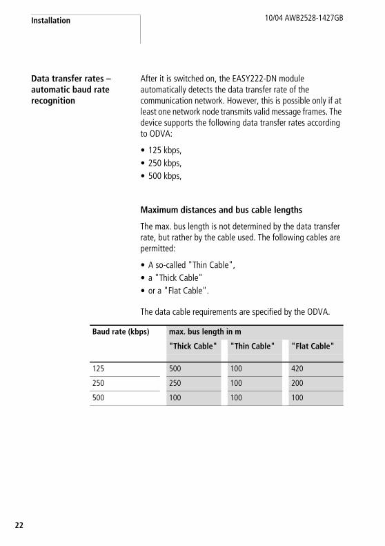
Data transfer rates – automatic baud rate recognition
After it is switched on, the EASY222-DN module automatically detects the data transfer rate of the communication network. However, this is possible only if at least one network node transmits valid message frames. The device supports the following data transfer rates according to ODVA:
• 125 kbps,• 250 kbps,• 500 kbps,
Maximum distances and bus cable lengths
The max. bus length is not determined by the data transfer rate, but rather by the cable used. The following cables are permitted:
• A so-called "Thin Cable",• a "Thick Cable"• or a "Flat Cable".
The data cable requirements are specified by the ODVA.
Baud rate (kbps) max. bus length in m
"Thick Cable" "Thin Cable" "Flat Cable"
125 500 100 420
250 250 100 200
500 100 100 100

3
10/04 AWB2528-1427GB
2
3 Operating the device
Initial power on X Before you switch on the device, verify that it is properly connected to the power supply, to the bus connectors and to the basic unit.
X Switch on the power supply for the basic unit and the EASY222-DN.
The LEDs of the EASY222-DN flicker. The device is in the mode for detection of the correct baud rate (a section “Data transfer rates – automatic baud rate recognition” on page 22). The GW information (intelligent station connected) is displayed on the basic unit.
As soon as the device in the network management is switched to the “Operational” status, the state of the GW changes to static even on the devices with a flashing GW, a section “Network status LED” on page 28).
If the EASY222-DN has factory settings (node ID = 127), you need to define the DeviceNet slave address.
Basic unit Device version GW display
easy600 04 static
easy700 From 01 flashing
easy800 04 static
From 05 flashing
MFD-CP8.. 01 static
From 02 flashing
Operating the device
24
10/04 AWB2528-1427GB
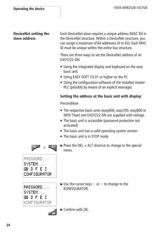
DeviceNet setting the slave address
Each DeviceNet slave requires a unique address (MAC ID) in the DeviceNet structure. Within a DeviceNet structure, you can assign a maximum of 64 addresses (0 to 63). Each MAC ID must be unique within the entire bus structure.
There are three ways to set the DeviceNet address of an EASY222-DN:
• Using the integrated display and keyboard on the easy basic unit
• Using EASY-SOFT V3.01 or higher on the PC• Using the configuration software of the installed master
PLC (possibly by means of an explicit message).
Setting the address at the basic unit with display:
Precondition
• The respective basic units (easy600, easy700, easy800 or MFD-Titan) and EASY222-DN are supplied with voltage.
• The basic unit is accessible (password protection not activated).
• The basic unit has a valid operating system version.• The basic unit is in STOP mode.
X Press the DEL + ALT shortcut to change to the special menu.
X Use the cursor keys Í or Ú to change to the KONFIGURATOR.
X Confirm with OK.
+
PASSWORD...SYSTEM...GB D F E ICONFIGURATOR
PASSWORD...SYSTEM...GB D F E IKONFIGURATOR

DeviceNet setting the slave address
5
10/04 AWB2528-1427GB
2
X Select the LINK.... menu with the easy800/MFD units
X Confirm with OK.
The DEVICENET menu appears.
X Set the address by means of the cursor keys:– Set the current numeric value via the Í or Ú keys.– You can change the current numeric value via ú or í.
X Accept the address with OK.
X Cancel address input with ESC.
NET...LINK...
DEVICENET
MAC ID 0026222-01.20- D
2 . . . 9 0 1 . . .o
0 0 0 1 P P 0 0 0 1
o1 0 9 . . . 2 . . .

Operating the device
26
10/04 AWB2528-1427GB
Information about the 4th display line:
Setting the address by means of EASY-SOFT
With EASY-SOFT, version 3.1‹Menu l Online l Configuration of expansion units›
With EASY-SOFT, from version 4.01‹Menu l Communication l Configuration l Expansion units l EASY222-DN›.
Setting the address via the master PLC
The configuration software supplied with your master PLC offers a further option of setting or modifying the MAC ID of the gateway. For more information, refer to the included PLC documentation.
xxx - xx . xx - xx
222-02.10- B
Hardware version, Index: b
Software version, OS version: 2.1
Device identity: EASY222-DN
h The menu is only available in the communication view; therefore please activate the “Communication” tab.
h The following applies for device version identity 01:
After you have modified the MAC ID via the basic unit, restart the EASY222-DN by switching power off and on. EASY222-DN devices with a version identity > 01 automatically accept the address.

LED status displays
7
10/04 AWB2528-1427GB
2
You can also use various other software packages to modify the MAC ID, e.g. by sending an explicit message. Do so by using the corresponding service of the DeviceNet object (section “DeviceNet object”, page 37).
LED status displays The expansion module EASY222-DN is equipped with two indicator LEDs for quick diagnostics. EASY222-DN monitors itself as well as the DeviceNet communication bus.
Module status LED
The dual-color LED (GREEN/RED) indicates the status of EASY222-DN. It monitors whether the device is fully functional and operates without fault.
OFF No power supply at the EASY222-DN.
GREEN EASY222-DN is in normal operational state.
GREEN flashing EASY222-DN is in standby mode. The configuration is faulty or incomplete, or a configuration does not exist.
RED flashing
An error has occurred. There is no need to replace the EASY222-DN.
RED A fatal error has occurred EASY222-DN. EASY222-DN must be replaced.
GREEN-RED flashing
EASY222-DN is performing a self-test.t
t
t
t
t
t

Operating the device
28
10/04 AWB2528-1427GB
Network status LED
The dual-color LED (GREEN/RED) indicates the status of the DeviceNet communication bus. This function monitors operability and correct operation of the EASY222-DN.
OFF EASY222-DN is offline. Either it is performing a DUP_MAC_ID test or power is missing at the device or bus.
GREEN flashing EASY222-DN is online. Communication has not yet been established.
GREEN EASY222-DN is online and the connection is active.
RED flashing Time-out of at least one I/O connection (time-out state).
RED A fatal network error has occurred. EASY222-DN has shut down communication.
GREEN-RED flashing
EASY222-DN has detected a network access error and is now in communication error state.
t
t
t
t
t
t

Cycle time of the "easy" basic unit
9
10/04 AWB2528-1427GB
2
Cycle time of the "easy" basic unit
Network traffic between the easy/MFD basic unit and the EASY222-DN via EASY-LINK extends the cycle scan time of the basic unit
In the worst case, this time can be extended by 25 ms.
Please take this factor into account when you calculate the response times of the basic unit.
EDS file You can implement EASY222-DN into the DeviceNet structure by means of a standardised EDS file (Electronic Data Sheet).
This EDS file primarily defines the polled I/O connection, the COS I/O connection and the cyclic I/O connection of the gateway. It does not contain data or parameters (easy object) for functions of the easy basic unit. These functions are accessed by means of explicit messages.
You can either order the current version of the EDS file directly at Moeller or download updates of this file from the Moeller homepage:
http://easy.moeller.net h Download h ...
Follow the “Link“ on this page.
A printed version of the EDS file can be found in the annex (a section “EDS file”, page 243).
h Note on the EDS file:
The Identity Object entry - Major Revision defines the current operating system state of the EASY222-DN communication module. As the device with a newer operating system version can deviate from the EDS description in this point, this entry must be modified accordingly, a section “Identity Object” on page 35.

30
10/04 AWB2528-1427GB

1
10/04 AWB2528-1427GB
3
4 DeviceNet functions
Object model EASY222-DN is based on the Communications Adapter Profile according to ODVA specifications (Release V2.0).
The DeviceNet object model can be used to describe all EASY222-DN functions. The object model reflects the principle of communication at the application layer. This manual deals in the following only with objects relevant for your application. Primary topic is the manufacturer-specific class easy object.
Figure 11: DeviceNet objects
Object
Polled I/OConnection
COS/Cyclic I/OConnection
Bit Strobed I/OConnection
Explicit MessageConnection
DynamicConnection
DeviceNetObject
Message RouterObject
Acknowledge HandlerObject
IdentityObject
easyObject
EASY-LINKProtocol Handler
AssemblyObject
Connection Object
DeviceNet

DeviceNet functions
32
10/04 AWB2528-1427GB
The DeviceNet objects in the illustration can be compiled again as “Management objects”, “Connection objects” and “Manufacturer-specific objects”. Their tasks will be briefly explained after the following.
Object address Service address
Function
Class ID [hex]
Instance ID[hex] [hex]
Attribute ID [hex]
a Management objects
Identity Object 01 01 a page 33
Message Router 02 01
b Connection objects
DeviceNet Object 03 01 a page 33
Connection Object 05 01 – 04, 04 – 0F
c Manufacturer-specific objects
easy Object 64 01 a page 38
Direct access: inputs/outputs, mode
Read 0E a chapter 5
Write 10
Extended access: time, image data, function blocks
32
easy600 a chapter 6
easy700 a chapter 7
easy800/MFD a chapter 8
Assembly Object 04 64 – 66

Object model
3
10/04 AWB2528-1427GB
3
a Management objectsThese define DeviceNet-specific data and functions and must be supported by all DeviceNet devices:
• Identity Object The Identity Object (Class ID 01hex) contains all data for unique identification of a network node, e.g. the Vendor ID, Device Type and Product Code. It also comprises the actual status of a device, the serial number and the product name.
Detailed information a page 35.
• Message Router ObjectThe Message Router Object (Class ID 02hex) provides access to all classes and instances in the device by means of explicit messages.
b Connection objectsDefine messages exchanged via DeviceNet:
• DeviceNet ObjectAll devices must support the DeviceNet object (Class ID: 03hex). It defines the physical interconnection of a device to the DeviceNet network, meaning it also contains the device address (MAC ID) and the currently set transmission speed, for example.
Detailed information a page 37.
• Connection ObjectThe Connection Object (Class ID: 05hex) is supported by all DeviceNet devices in at least one instance. It defines the access to data via I/O messages or explicit messages, the path and length of producer/consumer data, the CAN connection identifier, the watchdog and the error response.

DeviceNet functions
34
10/04 AWB2528-1427GB
c Manufacturer-specific objectsDefine device-specific data and functions (Application Objects, Parameter Object, Assembly Object).
• Application Objects – easy ObjectApplication objects (Class ID: 64hex) describe simple applications for automation engineering. They are either predefined in the DeviceNet object library or by the user.
Detailed information a page 38.
• Assembly ObjectsThe Assembly Object (Class ID: 04hex) provides the user with mapping options, i.e. attribute data of different instances in different classes can be grouped together to form a single attribute of an instance in an assembly object.

Object model
5
10/04 AWB2528-1427GB
3
Identity Object
Table 1: Attribute IDs of the Identity Object instance
Object address Function Access
Class ID Instance ID Attribute ID Service code
01hex 01hex a table 1 a table 2
Attribute ID
Access Name Description Size[byte]
1 Read Vendor ID The ODVA specifies the Vendor ID. For Moeller GmbH, this is 248dec.
2
2 Read Device type The EASY222-DN belongs to the communication adapters category. Its value is 12dec.
2
3 Read Product code The product code is defined by Moeller: 650dec. It describes the model number.
2
4 Read Device version
Two bytes are returned when reading the device version.
Hardware version,
The low byte defines the hardware version, the high byte the operating system version.
1
Operating system version
1
5 Read Status This attribute describes the global status of the device.
2
6 Read Serial number
The serial number of the device can be read with this attribute.
4
7 Read Product name
The product name EASY222-DN is stored as hex value in ASCII format.
12
9 Read Configuration consistency value
This attribute returns a counter value that monitors the number of modifications in non-volatile memory (E2PROM).
2
10 Read/Write
HeartbeatInterval
Defines an interval between heartbeat messages in [s].
2

DeviceNet functions
36
10/04 AWB2528-1427GB
Service codeThe Identity Object Instance and also the following instances support the services listed in the table below.
Table 2: Service code
Service codevalue
Service name Description
05hex Reset Calls the reset function of the communication module EASY222-DN.
0Ehex Get_Attribute_Single This service can be used to fetch the value of a selected attribute from the communication module.
10hex Set_Attribute_Single This service can be used to set a selected attribute in the device.

Object model
7
10/04 AWB2528-1427GB
3
DeviceNet object
The DeviceNet object instance is used to configure the communication module EASY222-DN and to define the physical environment. The Service Codes used for the Identity Object also apply in this case.
Table 3: Attribute IDs of the DeviceNet Object instance
Object address Function Access
Class ID Instance ID Attribute ID Service code
03hex 01hex a table 3 a table 2
Attribute ID
Access Name Description Size [byte]
1 Read/Write MAC ID The MAC ID represents the network address of a network node. It can be read and set for EASY222-DN via the fieldbus by means of this attribute. Range of values: 0 to 63dec. (a section “DeviceNet setting the slave address”, page 24)
1
2 Read/Write Baud rate This attribute can be used to read/set the data transfer rate for communication functions. Range of values: 0 to 2, 125 to 500 kbps (a section “Data transfer rates – automatic baud rate recognition”, page 22).
1
3 Read/Write BOI (Bus-Off interrupt)
This attribute can be used to define the reaction to a Bus-Off event (CAN-specific).
1
4 Read/Write Bus-Off counter
This values shows how often a Bus-Off event has occurred. Range of values: 0 to 255.
1

DeviceNet functions
38
10/04 AWB2528-1427GB
easy Object
The easy object can be used to access easy/MFD functions via the DeviceNet communication bus . The table below shows the attributes supported by this object. The two bytes of attributes 1 and 2 provide the diagnostic data of the device. You can use attribute 3 to access the outputs (S1 to S8) and attribute 4 to access the inputs (R1 of R16) of the basic unit.
By using a DeviceNet configuration software (e.g. RS Networx), you can map these data directly to the corresponding memory areas of a PLC.
Table 4: Attribute IDs of the Easy Object instance
Object address Function Access
Class ID Instance ID Attribute ID Service code
64hex 01hex a table 4 a table 5
Attribute ID
Access Name Description Size[byte]
1 Read easy Status This attribute can be used to read the status of easy (RUN or STOP).a table 6
1
2 Read CouplingModule Status
This attribute can be used to read the status of EASY-LINK.a table 6
1
3 Read Inputs – Send Data
easy transfers the input data to the DeviceNet bus. The easy outputs S1 to S8 must be used for this function. The structure of these 3 bytes is described in detail under page 49, section “Input data: Mode, S1 – S8”, .
3

Object model
9
10/04 AWB2528-1427GB
3
Service codeThe easy object instance supports the following services.
Table 5: Service code
4 Read/Write
Outputs – Receive Data
The DeviceNet bus transfers the data to easy. The easy inputs R1 to R16 must be used for this function. The structure of these 3 bytes is described in detail under page 51, section “Output data: mode, R1 – R16”, .
3
5 Read/Write
Predefined Outputs
This attribute can be used to preset the output data ("R" data) at the EASY222-DNduring start-up. The structure of these 3 bytes is described in detail under section “Output data: mode, R1 – R16”, page 51.
3
Attribute ID
Access Name Description Size[byte]
Service code value
Service name Description
0Ehex Get_Attribute_Single This service can be used to fetch the value of a selected attribute from the communication module.
10hex Set_Attribute_Single This service can be used to set a selected attribute in the device.
32hex Extended access1) This service can be used to address the supplementary parameters1) of the control relay:
1) Additional parameters are “Time”, “Image data” and “Function block”. Addressing of the parameters is easy specific and is described in chapters 5 – 7 in detail.Extended access is implemented via explicit message transfer. This transfer protocol allows the exchange of control data. Further information about the transfer protocol can be found in section “DeviceNet Communication profile” on page 41.

DeviceNet functions
40
10/04 AWB2528-1427GB
Change of State I/O connection
Table 6: Diagnostics data: 2 Byte
Byte Meaning Value Meaning
0 easy status (attribute ID 1)
00hex Static value.
1 Coupling module status (attribute ID 2)
00hex The basic unit is connected to the EASY222-DN gateway via EASY-LINK.
04hex The basic unit is either switched off or disconnected from the EASY222-DN gateway via EASY-LINK.
h When communication between the basic unit easy/MFD and the expansion unit EASY222-DN goes down, a corresponding error code will be generated in the third data byte. Furthermore, the Rx/Tx data of the gateway will be transferred with the value 00hex.

DeviceNet Communication profile
1
10/04 AWB2528-1427GB
4
DeviceNet Communication profile
DeviceNet is based on a connection-oriented communications model, i.e. data are exchanged only via the specific connections assigned to the units.
DeviceNet stations communicate either by means of I/O messages or explicit messages.
I/O Messages
I/O messages are used for exchanging high-priority process and application data across the network. Communication between DeviceNet nodes is based on the client/server model, i.e. a "producer" application transfers data to one or several "consumer" applications. It is quite possible in this case that several application objects are addressed in the same unit.
Prerequisite for communication between the units via I/O messages is the implementation of an I/O Messaging Connection Object. You can activate this function in two ways:
• Either by means of a static and in the unit already existing "l/O connection object" or via the “Predefined Master/Slave Connection Set“, or
• via a dynamically configured "l/O connection object", which you can configure using an Explicit Messaging Connection Object that already exist in the unit.

DeviceNet functions
42
10/04 AWB2528-1427GB
Explicit Messages
Explicit messages are used for exchanging low-priority configuration data, general management data or diagnostics data between two specific units across the PtP connection in a client/server system, in which the server always has to acknowledge client requests.
Same as for I/O messaging, the prerequisite for explicit messaging between the is the implementation of a “Connection Object“, namely the Explicit Messaging Connection Object“. This can be achieved either by activating an existing static connection object in the unit, or via the Predefined Master/Slave Connection Set“, or dynamically across the so-called UCMM port (Unconnected Message Manager Port) of a device.
All data of the function relay (easy basic unit) are processed by means of explicit messages. The master PLC can thus read/write access the parameters of the following functions.
• Time• Image data• Function blocks (counters, timers, analog value
comparators,...).

DeviceNet Communication profile
3
10/04 AWB2528-1427GB
4
General method of operationThe general method of operation with the EASY222-DN should be presented in the following. The acyclic data transfer is realised with the aid of explicit messages. The function blocks of the easy basic unit can be addressed via the service code = 32hex. The assigned attribute ID is here used to distinguish between different parameters and functions.
Digression:DeviceNet based on the standard CAN protocol and therefore uses an 11 bit message identifier. As a result 211 = 2048 messages (000hex - 7FFhex) are distinguishable. Six bits are sufficient for identification of a device as a DeviceNet network is limited to a maximum of 64 stations. These are referred to as the MAC-ID (device or node address).
Four message groups of differing sizes are available to suit the utilization model.
h The DeviceNet connection of the easy control relay to an SLC 500 requires specific control and handshake routines in the PLC program for the execution of the control commands (Explicit Messages).
The application note AN2700K17G supports the control commands of EASY222-DN. It provides subroutines in the program for controlling the required “Explicit Messages”, i.e. programming will be replaced by the call and theparameter assignment of the subroutine. Parameters are assigned by means of an integer file.
The self-extracting application note AN2700K17G.exe is available for download on the Moeller server at ftp://ftp.moeller.net/AUTOMATION/APPLICATION_Notes/an27k17d.exe.
Service code
Object address
Class ID Instance ID
32hex 64hex 01hex

DeviceNet functions
44
10/04 AWB2528-1427GB
In DeviceNet language terms the CAN identifier is referred to as the Connection ID. This is comprised of the identifier for the message group (Message ID) and the MAC ID of the device:
• The source and target addresses are possible as the MAC ID; the definition is dependant on the message group and message ID.
• The significance of the message is defined in the system with the message ID.
Four message groups are available in the DeviceNet world. The EASY222-DN uses message group 2. This group uses 512 CAN identifiers (400hex - 5FFhex). Most of the message IDs defined for this group are optional and defined for use of the “Predefined Master/Slave Connection Sets”. A message ID is used for network management. The priority is primarily determined by the device address and then by the message ID. If the bit position is examined in detail, you will find that a CAN controller with an 8 bit mask is capable of filtering out its group 2 messages.

DeviceNet Communication profile
5
10/04 AWB2528-1427GB
4
The data transfer on the DeviceNet communication bus is indicated in the following table. The data flow indicates the telegram for reading the date and time in the easy700 (a section “Read/write date and time” on page 101).
The EASY222-DN communication module has MAC ID = 3. It must be noted with the data stream that access is implemented in fragmented form. More information can be found in the ODVA specification.
Connection ID = CAN identifier Meaning
10 9 8 7 6 5 4 3 2 1 0
1 0 MAC ID Message ID Message group 2
1 0 Source MAC ID 0 0 0 Master’s I/O Bit–Strobe Command Message
1 0 Source MAC ID 0 0 1 Reserved for Master’s Use – Use is TBD
1 0 Destination MAC ID 0 1 0 Master’s Change of State or Cyclic Acknowledge Message
1 0 Source MAC ID 0 1 1 Slave’s Explicit/ Unconnected Response Messages
1 0 Destination MAC ID 1 0 0 Master’s Explicit Request Messages
1 0 Destination MAC ID 1 0 1 Master’s I/O Poll Command/Change of State/Cyclic Message
1 0 Destination MAC ID 1 1 0 Group 2 Only Unconnected Explicit Request Messages
1 0 Destination MAC ID 1 1 1 Duplicate MAC ID Check Messages
Source: ODVA- DeviceNet Specification Release 2.0, Chapter 7-2

DeviceNet functions
46
10/04 AWB2528-1427GB
Description ID(hex)
Length DeviceNet – Byte (hex)
0 1 2 3 4 5 6 7
Master sends a request (hex) with: 41C 8 80 00 32 64 01 93 05 00
Byte 2 - service code = 32Byte 3 - CLASS ID = 64 Byte 4 - Instance ID = 01
DeviceNet specific
Byte 5 - Attribute ID = 93Byte 6 - Len = 05Byte 7 - Index = 0
EASYLINK specific
Confirmation of the slave (Fragmentation protocol)
41B 3 80 C0 00
Master sends remaining EASYLINK byte 41C 6 80 01 00 00 00 00
Byte 2 - Data 1 = 00Byte 3 - Data 2 = 00Byte 4 - Data 3 = 00Byte 5 - Data 4 = 00
Acknowledgement of the slave(Fragmentation protocol)
41B 3 80 C1 00
Slave sends a response to the request 41B 8 80 00 B2 C2 05 00 05 09
Byte 3 – response = C2 (read successful)Byte 4 – Len = 05Byte 5 – Index = 00Byte 6 – Data 1 = 05
Acknowledgement from master (Fragmentation Protocol)
41C 3 80 C0 00
Slave sends remaining EASY-LINK data: 41B 5 80 81 0D 05 04
Data 2 = 0DData 3 = 05Data 4 = 04
Acknowledgement from master (Fragmentation protocol)
41C 3 80 C1 00

7
10/04 AWB2528-1427GB
4
5 Direct data exchange with easy/MFD (Polled I/O Connection)
The DeviceNet master can exchange the following data with the easy/MFD via the direct cyclic data exchange:
• Write operation– Setting or /resetting of the easy/MFD inputs– Determination of the RUN/STOP mode.
• Read operation– Scanning the output states of the easy/MFD– Scanning the mode of the easy/MFD.
In order to transfer data between the slave EASY222-DN and a DeviceNet master control, you must map the respective cyclic data to the respective slave configuration.
h The interconnection to the DeviceNet controls from Allen Bradley is implemented using an assignment table in the RS-NetWorx software tool.

Direct data exchange with easy/MFD (Polled I/O Connection)
48
10/04 AWB2528-1427GB
Figure 12: Input and output data relative to the DeviceNet master
h The terms “input data” and “output data” are used relative to the point of view of the DeviceNet master.
Inputs R1 – R16
Outputs S1 – S8
easy/MFD
DeviceNet master
Write:Output data
Read:Input data
Outputs Inputs

Input data: Mode, S1 – S8
9
10/04 AWB2528-1427GB
4
Input data:Mode, S1 – S8
Attribute ID: 3The cyclic data transfer between DeviceNet master and the EASY222-DN slave is provided by the input data byte 0, 1 and 2.
Table 7: Byte 0 to 2: input data, mode
The master reads the following data from bytes 0, 1 and 2:
Table 8: Byte 0: Operating mode
0 = status "0“ 1 = status "1"
Example:Value 21hex = 00100001bin:"easy" is in RUN mode and operates with input delay
Byte Meaning Value
0 Operating mode scan a table 8
1 Scan status of the easy outputs S1 to S8
a table 9
2 Not used 00hex
easy identification Bit
7 6 5 4 3 2 1 0STOP/RUN
without input delay 0 0 0 1 0 0 0 0/1
with input delay 0 0 1 0 0 0 0 0/1

Direct data exchange with easy/MFD (Polled I/O Connection)
50
10/04 AWB2528-1427GB
Table 9: Byte 1: Status of the easy/MFD outputs S1 to S8
0 = status "0“ 1 = status "1"
Example:Value 19hex = 00011001bin:S5, S4 and S1 are active
Byte 2: not used
easy/MFD Bit
7 6 5 4 3 2 1 0
S1 0/1
S2 0/1
S3 0/1
S4 0/1
S5 0/1
S6 0/1
S7 0/1
S8 0/1
h If control commands and I/O data are used at the same time:
• The inputs will retain their previous state until this control command has been executed.
• The input bytes will be updated again after the data exchange control command has been terminated.
If the status value of the coupling module is invalid (= 04hex), then byte 1 (data byte) is transferred with the value 00hex to the communication bus.

Output data: mode, R1 – R16
1
10/04 AWB2528-1427GB
5
Output data:mode, R1 – R16
Attribute ID: 4The cyclic data transfer between DeviceNet master and the EASY222-DN slave is provided by the output data byte 0, 1 and 2.
Table 10: Byte 0 to 2: output data, mode
The master writes the following data to the bytes 0, 1 and 2:
Table 11: Byte 0: Operating mode
0 = status "0“ 1 = status "1"
Explanation:
Value 14hex = 00010100bin:Byte 0 must always contain this value if data are to be written to the easy/MFD basic unit via the EASY222-DN gateway.
Value 34hex = 00110100bin:This value sets the easy status from STOP to RUN. It is only interpreted as command and therefore does not permit an additional transfer of data. The index value 14hex must be used in this situation.
Byte Meaning Value
0 Determine mode a table 11
1 Setting/resetting of the easy/MFD inputs R9 to R16
a table 12
2 Setting/resetting of the easy/MFD inputs R1 to R8
a table 13
easy operating mode Bit
7 6 5 4 3 2 1 0
Index for setting the basic unit to safety state
0 0 0 0 0 0 0 0
Index for transferring valid data 0 0 0 1 0 1 0 0
RUN command 0 0 1 1 0 1 0 0
STOP command 0 1 0 0 0 1 0 0

Direct data exchange with easy/MFD (Polled I/O Connection)
52
10/04 AWB2528-1427GB
Value 44hex = 01000100bin:This value sets the "easy" status from RUN to STOP. It is also used only as command and is therefore based on the same operating principle as the RUN command.
Value 00hex = 00000000bin:If this value is written to the control byte, the gateway overwrites the R data with zero. This function is of interest only if a master is to be set to STOP mode and as resultant measure transfers zero values to all I/O in order to ensure safety state.
h Even if the I/O of a control relay can be assigned directly to a specific memory area of the master PLC, it is nonetheless important to conform with the correct data structure format (e.g.: input data byte 0 = 14hex).

Output data: mode, R1 – R16
3
10/04 AWB2528-1427GB
5
Table 12: Byte 1: Setting/resetting of the easy/MFD inputs R9 to R16
0 = status "0“ 1 = status "1"
Example:Value 19hex = 00011001bin:Enable R13, R12 and R9.
easy/MFD Bit
7 6 5 4 3 2 1 0
R9 0/1
R10 0/1
R11 0/1
R12 0/1
R13 0/1
R14 0/1
R15 0/1
R16 0/1

Direct data exchange with easy/MFD (Polled I/O Connection)
54
10/04 AWB2528-1427GB
Table 13: Byte 2: Setting/resetting of the easy/MFD inputs R1 to R8
0 = status "0“ 1 = status "1"
Example:Value 2Bhex = 0010 1011bin:Enables R6, R4, R2 and R1.
easy/MFD input Bit
7 6 5 4 3 2 1 0
R1 0/1
R2 0/1
R3 0/1
R4 0/1
R5 0/1
R6 0/1
R7 0/1
R8 0/1
h If control commands and I/O data are used at the same time:
• The inputs will retain their previous state until this control command has been executed.
• The input bytes will be updated after the data exchange control command has been executed.
5
04/04 AWB2528-1479GB
5
6 Control Commands for easy600
Control commands can be used to initiate data exchange for special services:
• „Read and write date and time, summer and winter time“ (page 57)
• „Read image data“ (page 61)• „Read/write function blocks“ (page 72).
The master PLC in this case falls back upon the message transfer protocol of the explicit messages. All parameters are addressed via the Service Code 32hex. The assigned attribute ID is here used to distinguish between different parameters.
A data exchange procedure is required in order to ensure the safe exchange of data via DeviceNet from master to slave and vice versa.
Service code Object address
Class ID Instance ID
32hex 64hex 01hex
h Note!The I/O data retain their previously defined state while a control command is being executed. The I/O data will not be updated until data exchange for the control command has been terminated.
i Caution!You may use only the values specified for the instruction code.Verify data to be transferred in order to avoid unnecessary errors.

Control Commands for easy600
56
04/04 AWB2528-1479GB
The master transmits a control command to initiate data exchange between the communication partners. The slave always returns an answer to this request, which indicates whether data has been exchanged or not. An error code will be returned if data exchange has failed. This code is precisely defined in the ODVA specifications.a section “References”, page 8
h The operating mode of the basic unit must correspond with the status indicated at the LEDs when the various parameters are being set.

Read and write date and time, summer and winter time
7
04/04 AWB2528-1479GB
5
Read and write date and time,summer and winter time Telegram structure
Byte Meaning Value (hex), sent by Bit
m s Master Slave 7 6 5 4 3 2 1 0
Attribute ID
Read 5D – 0 1 0 1 1 1 0 1
Write A 2 – 0 0 1 0 1 0 1 0
0 Answer
Read successful – C2 1 1 0 0 0 0 1 0
Write successful – C1 1 1 0 0 0 0 0 1
Command rejected
– C0 1 1 0 0 0 0 0 0
0 1 Weekday
Read operation 00 a table 14
Write operation a table 14 00
1 2 Hour
Read operation 00 a table 15
Write operation a table 15 00
2 3 Minute
Read operation 00 a table 16
Write operation a table 16 00
3 4 Summer/winter time
Read operation 00 a table 17
Write operation a table 17 00
m = master
s = slave
Control Commands for easy600
58
04/04 AWB2528-1479GB
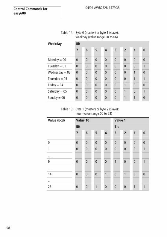
Table 14: Byte 0 (master) or byte 1 (slave): weekday (value range 00 to 06)
Table 15: Byte 1 (master) or byte 2 (slave): hour (value range 00 to 23)
Weekday Bit
7 6 5 4 3 2 1 0
Monday = 00 0 0 0 0 0 0 0 0
Tuesday = 01 0 0 0 0 0 0 0 1
Wednesday = 02 0 0 0 0 0 0 1 0
Thursday = 03 0 0 0 0 0 0 1 1
Friday = 04 0 0 0 0 0 1 0 0
Saturday = 05 0 0 0 0 0 1 0 1
Sunday = 06 0 0 0 0 0 1 1 0
Value (bcd) Value 10 Value 1
Bit Bit
7 6 5 4 3 2 1 0
0 0 0 0 0 0 0 0 0
1 0 0 0 0 0 0 0 1
....
9 0 0 0 0 1 0 0 1
....
14 0 0 0 1 0 1 0 0
...
23 0 0 1 0 0 0 1 1
Read and write date and time, summer and winter time
9
04/04 AWB2528-1479GB
5
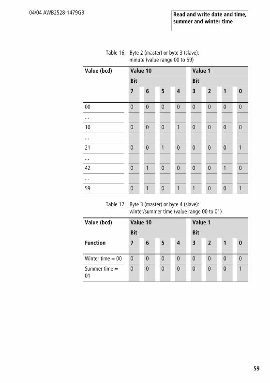
Table 16: Byte 2 (master) or byte 3 (slave): minute (value range 00 to 59)
Table 17: Byte 3 (master) or byte 4 (slave): winter/summer time (value range 00 to 01)
Value (bcd) Value 10 Value 1
Bit Bit
7 6 5 4 3 2 1 0
00 0 0 0 0 0 0 0 0
...
10 0 0 0 1 0 0 0 0
...
21 0 0 1 0 0 0 0 1
...
42 0 1 0 0 0 0 1 0
...
59 0 1 0 1 1 0 0 1
Value (bcd) Value 10 Value 1
Bit Bit
Function 7 6 5 4 3 2 1 0
Winter time = 00 0 0 0 0 0 0 0 0
Summer time = 01
0 0 0 0 0 0 0 1
Control Commands for easy600
60
04/04 AWB2528-1479GB
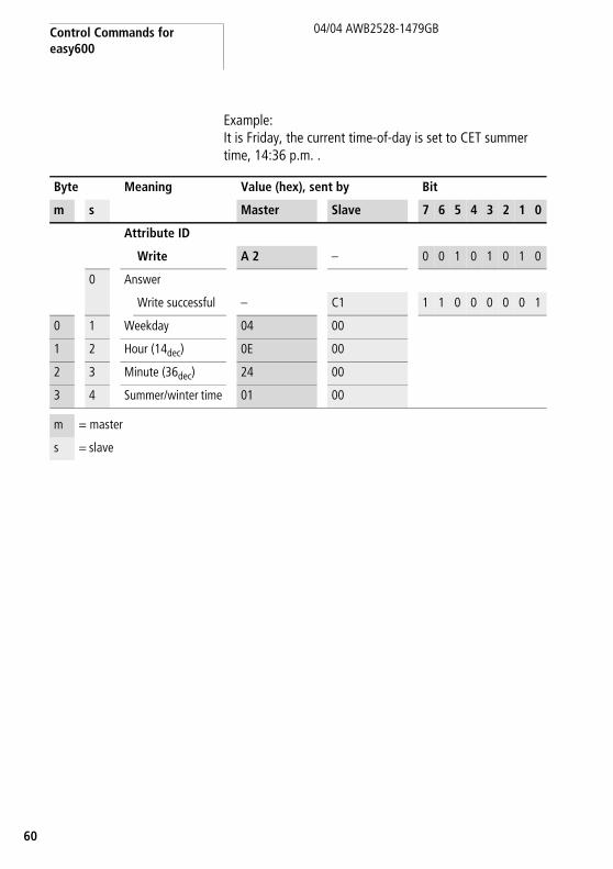
Example:It is Friday, the current time-of-day is set to CET summer time, 14:36 p.m. .
Byte Meaning Value (hex), sent by Bit
m s Master Slave 7 6 5 4 3 2 1 0
Attribute ID
Write A 2 – 0 0 1 0 1 0 1 0
0 Answer
Write successful – C1 1 1 0 0 0 0 0 1
0 1 Weekday 04 00
1 2 Hour (14dec) 0E 00
2 3 Minute (36dec) 24 00
3 4 Summer/winter time 01 00
m = master
s = slave

Read image data
1
04/04 AWB2528-1479GB
6
Read image data General notes on working with image data
When writing to image data, it must be remembered that an image (e.g. inputs, outputs,... ) used in the easy/MFD program is also written cyclically by the actual program. The only image data that is unchanged is the data that is not used in the program and is therefore not overwritten in the program cycle. This operating principle also means that an image written via EASYLINK, such as output data is only then output at the physical outputs of the easy/MFD when the control relay is in Run mode.
Overview
Read
input
s
Image datawritten
Writeoutputs
easy/MFDProgram cycle
(0 ... 20 ms)
System time
easyLinkInterrupt function
(every 12 or 25 ms)
Image datawritten
Operands Meaning Read/write Attribute ID
Page
I1 – I16, P1 – P4, ESC/OK/DEL/ALT
„Digital inputs, P buttons and operating buttons“
5C 62
I7 – I8 „Analog inputs: I7 – I8“ 5B 65
T1 – T8, C1 – C8, Ö1 – Ö4, A1 – A8,
„Timing relays, counter relays, timer switch, analog value comparator“
5E 66
M1 – M16, Q1 – Q8, D1 – D8
„Auxiliary relay (marker), digital outputs, text display“
5F 69

Control Commands for easy600
62
04/04 AWB2528-1479GB
Digital inputs, P buttons and operating buttons
Using the following command the logical states of the digital button inputs P1 to P4 as well as the logical states of the digital inputs I1 to I16 can be read.
The status of the P buttons is only displayed if
• a P button is used in the circuit diagram and• the pushbuttons are activated on the device.
Telegram structure
Byte Meaning Value (hex), sent by Bit
m s Master Slave 7 6 5 4 3 2 1 0
Attribute ID
Read 5C – 0 1 0 1 1 1 0 0
0 Answer
Read successful – C2 1 1 0 0 0 0 1 0
Command rejected
– C0 1 1 0 0 0 0 0 0
0 1 Status of inputs I1 to I8
00 a table 18
1 2 State of the inputs I9 to I16
00 a table 19
2 3 State of the buttons 00 a table 20
m = master
s = slave

Read image data
3
04/04 AWB2528-1479GB
6
Table 18: Byte 1: Status of inputs I1 to I8
Table 19: Byte 2: status inputs I9 to I16
Value Bit
7 6 5 4 3 2 1 0
I1 0/1
I2 0/1
I3 0/1
I4 0/1
I5 0/1
I6 0/1
I7 0/1
I8 0/1
Value 0 = switched off, Value 1 = switched on
Value Bit
7 6 5 4 3 2 1 0
I9 0/1
I10 0/1
I11 0/1
I12 0/1
I13 0/1
I14 0/1
I15 0/1
I16 0/1
Value 0 = switched off, Value 1 = switched on
Control Commands for easy600
64
04/04 AWB2528-1479GB
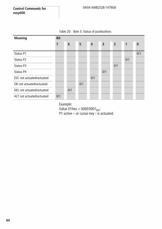
Table 20: Byte 3: Status of pushbuttons
Example:Value 01hex = 00000001bin:P1 active – or cursor key í is actuated.
Meaning Bit
7 6 5 4 3 2 1 0
Status P1 0/1
Status P2 0/1
Status P3 0/1
Status P4 0/1
ESC not actuated/actuated 0/1
OK not actuated/actuated 0/1
DEL not actuated/actuated 0/1
ALT not actuated/actuated 0/1

Read image data
5
04/04 AWB2528-1479GB
6
Analog inputs: I7 – I8
The values of both analog inputs I7, I8 (only EASY...-DC-..) are read with the following command.
Analog inputs I7 and I8 (byte 1 and byte 2)These two bytes contain the process variable of the analog inputs I7 and I8. Their value lies between 00 and 99, which is equivalent to a voltage level of 0 to 9.9 V at the inputs. The corresponding values are returned in hexadecimal format.
Example:
Byte Meaning Value (hex), sent by Bit
m s Master Slave 7 6 5 4 3 2 1 0
Attribute ID
Read 5B – 0 1 0 1 1 0 1 1
0 Answer
Read successful – C2 1 1 0 0 0 0 1 0
Command rejected
– C0 1 1 0 0 0 0 0 0
0 1 Analog value of I7 00 See below
1 2 Analog value of I8 00
m = master
s = slave
Byte Value
Description
0 42hex The read request has been executed. Data follow.
1 20hex Voltage level at input I7 = 3.2 V.
2 31hex Voltage level at input I8 = 4.9 V.

Control Commands for easy600
66
04/04 AWB2528-1479GB
Timing relays, counter relays, timer switch, analog value comparator
The following command reads the logic state of all timing relays, counters, time switches and analog value comparators.
Telegram structure
Byte Meaning Value (hex), sent by Bit
m s Master Slave 7 6 5 4 3 2 1 0
Attribute ID
Read 5E – 0 1 0 1 1 1 1 0
0 Answer
Read successful – C2 1 1 0 0 0 0 1 0
Command rejected
– C0 1 1 0 0 0 0 0 0
0 1 Status of timing relay
00 a table 21
1 2 Counter relay status 00 a table 22
2 3 Time switch status 00 a table 23
3 4 Analog value comparator status
00 a table 24
m = master
s = slave

Read image data
7
04/04 AWB2528-1479GB
6
Table 21: Byte 1: Status of timing relays
Example:Value 2Bhex = 00101011bin:T6, T4, T2 and T1 are active.
Table 22: Byte 2: Status of the counter relays
Example:Value 19hex = 00011001bin:C5, C4 and C1 are active
Bit
7 6 5 4 3 2 1 0
T1 0/1
T2 0/1
T3 0/1
T4 0/1
T5 0/1
T6 0/1
T7 0/1
T8 0/1
Bit
7 6 5 4 3 2 1 0
C1 0/1
C2 0/1
C3 0/1
C4 0/1
C5 0/1
C6 0/1
C7 0/1
C8 0/1

Control Commands for easy600
68
04/04 AWB2528-1479GB
Table 23: Byte 3: Status of time switches
Example:Value 08hex = 00001000bin:W3 is active.
Table 24: Byte 4: Status of analog value comparators
Example:Value 84hex = 10001000bin:A3 and A8 are active.
Bit
7 6 5 4 3 2 1 0
Ö1 0/1
Ö2 0/1
Ö3 0/1
Ö4 0/1
0
0
0
0
Bit
7 6 5 4 3 2 1 0
A1 0/1
A2 0/1
A3 0/1
A4 0/1
A5 0/1
A6 0/1
A7 0/1
A8 0/1
Read image data
9
04/04 AWB2528-1479GB
6
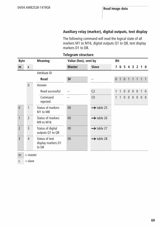
Auxiliary relay (marker), digital outputs, text display
The following command will read the logical state of all markers M1 to M16, digital outputs Q1 to Q8, text display markers D1 to D8.
Telegram structure
Byte Meaning Value (hex), sent by Bit
m s Master Slave 7 6 5 4 3 2 1 0
Attribute ID
Read 5F – 0 1 0 1 1 1 1 1
0 Answer
Read successful – C2 1 1 0 0 0 0 1 0
Command rejected
– C0 1 1 0 0 0 0 0 0
0 1 Status of markers M1 to M8
00 a table 25
1 2 Status of markers M9 to M16
00 a table 26
2 3 Status of digital outputs Q1 to Q8
00 a table 27
3 4 Status of text display markers D1 to D8
00 a table 28
m = master
s = slave

Control Commands for easy600
70
04/04 AWB2528-1479GB
Table 25: Byte 1: Status of the marker relays 1 to 8
Example:Value 2Bhex = 00101011bin:M6, M4, M2 and M1 are active.
Table 26: Byte 2: Status of the marker relays 9 to 16
Example:Value 19hex = 00011001bin:M13, M12 and M9 are active
Bit
7 6 5 4 3 2 1 0
M1 0/1
M2 0/1
M3 0/1
M4 0/1
M5 0/1
M6 0/1
M7 0/1
M8 0/1
Bit
7 6 5 4 3 2 1 0
M9 0/1
M10 0/1
M11 0/1
M12 0/1
M13 0/1
M14 0/1
M15 0/1
M16 0/1

Read image data
1
04/04 AWB2528-1479GB
7
Table 27: Byte 3: Status of digital outputs Q1 to Q8
Example:Value A8hex = 10101000bin:Q8, Q6 and Q4 are active.
Table 28: Byte 4: Status of text display markers D1 to D8
Example:Value 84hex = 10000100bin:D3 and D8 are active.
Bit
7 6 5 4 3 2 1 0
Q1 0/1
Q2 0/1
Q3 0/1
Q4 0/1
Q5 0/1
Q6 0/1
Q7 0/1
Q8 0/1
Bit
7 6 5 4 3 2 1 0
D1 0/1
D2 0/1
D3 0/1
D4 0/1
D5 0/1
D6 0/1
D7 0/1
D8 0/1

Control Commands for easy600
72
04/04 AWB2528-1479GB
Read/write function blocks
Overview
The first data byte of the string to be written to Instruction represents an instruction to easy600 and defines the significance of the remaining six data bytes. The table below lists the instruction set.
Operands Meaning Instruction Page
A1 – A8 „Analog value comparator A1 – A8: write actual values (function, comparison values)“
22hex – 29hex 73
C1 – C8 „Counter relays C1 – C8: read actual value“ 3Bhex – 42hex 76
„Counter relay C1 – C8: write reference value“ 09hex – 10hex 78
„Counter relay C1 – C8: read reference value“ 43hex – 4Ahex 80
T1 – T8 „Timing relays T1 – T8: read actual value (timing range, actual value, switching function)“
2Bhex – 32hex 82
„Timing relays T1 – T8: write parameters (timing range, reference value, switching function)“
01hex – 08hex 86
Ö1 – Ö4 “Switching timer Ö1 – Ö4: read actual value (channel, ON time, OFF time)”
4Bhex – 5Ahex 90
“Switching timer Ö1 – Ö4: read setpoint value (channel, ON time, OFF time)”
12hex – 21hex 94
Read/write function blocks
3
04/04 AWB2528-1479GB
7
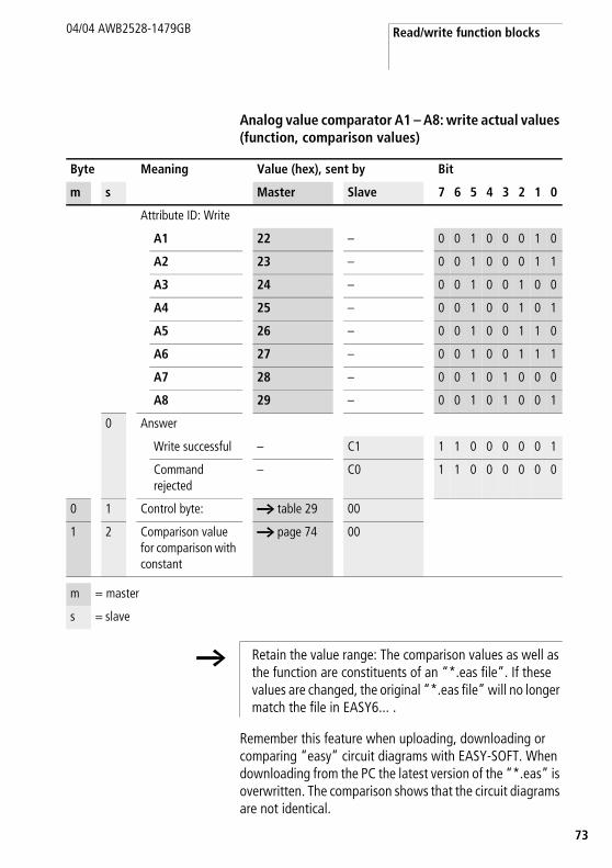
Analog value comparator A1 – A8: write actual values (function, comparison values)
Remember this feature when uploading, downloading or comparing “easy” circuit diagrams with EASY-SOFT. When downloading from the PC the latest version of the “*.eas” is overwritten. The comparison shows that the circuit diagrams are not identical.
Byte Meaning Value (hex), sent by Bit
m s Master Slave 7 6 5 4 3 2 1 0
Attribute ID: Write
A1 22 – 0 0 1 0 0 0 1 0
A2 23 – 0 0 1 0 0 0 1 1
A3 24 – 0 0 1 0 0 1 0 0
A4 25 – 0 0 1 0 0 1 0 1
A5 26 – 0 0 1 0 0 1 1 0
A6 27 – 0 0 1 0 0 1 1 1
A7 28 – 0 0 1 0 1 0 0 0
A8 29 – 0 0 1 0 1 0 0 1
0 Answer
Write successful – C1 1 1 0 0 0 0 0 1
Command rejected
– C0 1 1 0 0 0 0 0 0
0 1 Control byte: a table 29 00
1 2 Comparison value for comparison with constant
a page 74 00
m = master
s = slave
h Retain the value range: The comparison values as well as the function are constituents of an “*.eas file”. If these values are changed, the original “*.eas file” will no longer match the file in EASY6... .

Control Commands for easy600
74
04/04 AWB2528-1479GB
Table 29: Byte 0: control byte
Example:82hex = 10000010bin means that the selected analogue value comparator will be enabled in the circuit diagram of the basic unit as soon as the analogue value input I7 f the defined constant (a byte 1).
Comparison value (Byte1)This byte contains the reference value constant. Its value lies between 0 and 99 and is equivalent to a reference voltage of 0.0 to 9.9 V. This value you must also specify in hexadecimal format.
Example:The reference value = 20hex is equivalent to an analog voltage of 3.2 V.
Meaning Bit
7 6 5 4 3 2 1 0
Compare: “f” 0
Compare: “F” 1
I7 to I8 0 0
I7 with constant 0 1
I8 with constant 1 0
Fixed 0 0 0
Does not appear in the parameter menu
1
Appears in the parameter menu
0
Execution 1

Read/write function blocks
5
04/04 AWB2528-1479GB
7
ExampleThe analog value comparator A8 has the following settings:
• Compare I7 < 4.7 V
The master initiates the command to reduce the comparison value to 4.2 V.
0
The slave responds with the following telegram:
Byte Meaning Value (hex) Bit
7 6 5 4 3 2 1 0
Attribute ID: A8 29 0 0 1 0 1 0 0 1
0 Control byte: l 1 0 0 0 0 0 1 1
1 Comparison value for comparison with constant
A 2 0 0 1 0 1 0 1 0
Byte Meaning Value (hex) Bit
7 6 5 4 3 2 1 0
0 Response: Write successful
C1 1 1 0 0 0 0 0 1
1 Comparators 00
2 Comparison value for comparison with constant
00
Control Commands for easy600
76
04/04 AWB2528-1479GB
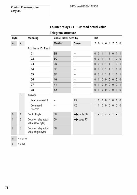
Counter relays C1 – C8: read actual value
Telegram structure
Byte Meaning Value (hex), sent by Bit
m s Master Slave 7 6 5 4 3 2 1 0
Attribute ID: Read
C1 3B – 0 0 1 1 1 0 1 1
C2 3C – 0 0 1 1 1 1 0 0
C3 3D – 0 0 1 1 1 1 0 1
C4 3E – 0 0 1 1 1 1 1 0
C5 3F – 0 0 1 1 1 1 1 1
C6 40 – 0 1 0 0 0 0 0 0
C7 41 – 0 1 0 0 0 0 0 1
C8 42 – 0 1 0 0 0 0 1 0
0 Answer
Read successful – C2 1 1 0 0 0 0 1 0
Command rejected
– C0 1 1 0 0 0 0 0 0
0 1 Control byte: 00 a table 30 x x x x x x x x
1 2 Counter relay actual value (low byte)
00 a page 77
2 3 Counter relay actual value (high byte)
00
m = master
s = slave

Read/write function blocks
7
04/04 AWB2528-1479GB
7
Table 30: Byte 1: control byte
Example:Value 80hex = 10000000bin:The actual value of the counter relay is set and appears in the parameter menu.
Process variable (byte 2 and byte 3)These two bytes define the process variable of the counter relay. The value of the process variable can lie within the range 0 to 9999dec. In order to determine the corresponding process variable, you need to convert the 16-bit hexadecimal low and high values into the decimal format.
Example:High value:10hexLow value: DEhex10DEhex = 4318dec
Meaning Bit
7 6 5 4 3 2 1 0
Not used 0 0 0 0 0 0
Does not appear in the parameter menu 1
Appears in the parameter menu 0
Execution(will be processed in the circuit diagram)
1

Control Commands for easy600
78
04/04 AWB2528-1479GB
Counter relay C1 – C8: write reference value
Telegram structure
Value range of the counter values: 0000 to 9999
This value is a constituent of an EASY-SOFT file (*.eas). If these values are changed, the original “*.eas file” will no longer match the file in EASY6... .
Byte Meaning Value (hex), sent by Bit
m s Master Slave 7 6 5 4 3 2 1 0
Attribute ID: Write
C1 09 – 1 0 0 0 1 0 0 1
C2 0A – 1 0 0 0 1 0 1 0
C3 0B – 1 0 0 0 1 0 1 1
C4 0C – 1 0 0 0 1 1 0 0
C5 0D – 1 0 0 0 1 1 0 1
C6 0E – 1 0 0 0 1 1 1 0
C7 0F – 1 0 0 0 1 1 1 1
C8 10 – 1 0 0 1 0 0 0 0
0 Answer
Write successful – C1 1 1 0 0 0 0 0 1
Command rejected
– C0 1 1 0 0 0 0 0 0
0 1 Control byte: a table 31 00
1 2 Setpoint value (low byte)
a page 79 00
2 3 Setpoint value (high byte)
00
m = master
s = slave
h Keep within the value range.

Read/write function blocks
9
04/04 AWB2528-1479GB
7
Remember this feature when uploading, downloading or comparing “easy” circuit diagrams with EASY-SOFT.
When downloading from the PC the latest version of the “*.eas” is overwritten.
The comparison shows that the circuit diagrams are not identical.
Table 31: Byte 0: control byte
Example:Value 80hex = 1000000bin:The reference value will be written to the selected timing relay and appears in the parameter menu.
Setting the reference value(byte 1 and byte 2)These two bytes determine the reference value of the counter relay. The reference value can be set within the range from 0 to 9999dec. To do so, you must convert the required decimal into the equivalent hexadecimal value and then split it up into the low-byte and high-byte.
Example:Reference value = 4318dec = 10DEhex:Low-value: DEhexHigh-value: 10hex
Meaning Bit
7 6 5 4 3 2 1 0
Not used 0 0 0 0 0 0
Does not appear in the parameter menu
1
Appears in the parameter menu 0
Execution 1
Control Commands for easy600
80
04/04 AWB2528-1479GB
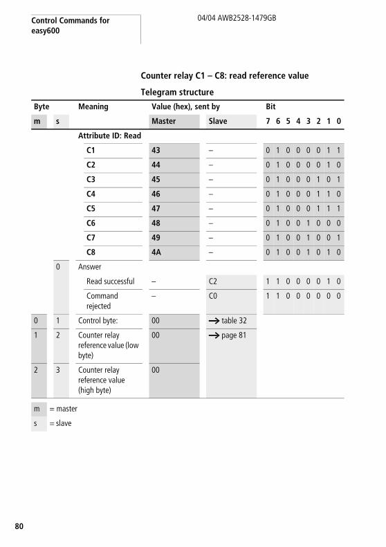
Counter relay C1 – C8: read reference value
Telegram structure
Byte Meaning Value (hex), sent by Bit
m s Master Slave 7 6 5 4 3 2 1 0
Attribute ID: Read
C1 43 – 0 1 0 0 0 0 1 1
C2 44 – 0 1 0 0 0 0 1 0
C3 45 – 0 1 0 0 0 1 0 1
C4 46 – 0 1 0 0 0 1 1 0
C5 47 – 0 1 0 0 0 1 1 1
C6 48 – 0 1 0 0 1 0 0 0
C7 49 – 0 1 0 0 1 0 0 1
C8 4A – 0 1 0 0 1 0 1 0
0 Answer
Read successful – C2 1 1 0 0 0 0 1 0
Command rejected
– C0 1 1 0 0 0 0 0 0
0 1 Control byte: 00 a table 32
1 2 Counter relay reference value (low byte)
00 a page 81
2 3 Counter relay reference value (high byte)
00
m = master
s = slave

Read/write function blocks
1
04/04 AWB2528-1479GB
8
Table 32: Byte 1: control byte
Example:Value 80hex = 10000000bin:The process value of the counter relay is set and appears in the parameter menu.
Reference value (byte 2 and byte 3)These two bytes determine the reference value of the counter relay. The reference value can lie within the value range 0 to 9999dec. In order to determine the corresponding reference value, you need to convert the 16-bit hexadecimal low and high value into the decimal format.
Example:High value: 10hexLow value: DEhex10DEhex = 4318dec
Meaning Bit
7 6 5 4 3 2 1 0
Not used 0 0 0 0 0 0
Does not appear in the parameter menu 1
Appears in the parameter menu 0
Execution (is being processed in the circuit diagram)
1

Control Commands for easy600
82
04/04 AWB2528-1479GB
Timing relays T1 – T8: read actual value (timing range, actual value, switching function)
Telegram structure
Byte Meaning Value (hex), sent by Bit
m s Master Slave 7 6 5 4 3 2 1 0
Attribute ID: Read
T1 2B – 0 0 1 0 1 0 1 1
T2 2C – 0 0 1 0 1 1 0 0
T3 2D – 0 0 1 0 1 1 0 1
T4 2E – 0 0 1 0 1 1 1 0
T5 2F – 0 0 1 0 1 1 1 1
T6 30 – 0 0 1 1 0 0 0 0
T7 31 – 0 0 1 1 0 0 0 1
T8 32 – 0 0 1 1 0 0 1 0
0 Answer
Read successful – C2 1 1 0 0 0 0 1 0
Command rejected
– C0 1 1 0 0 0 0 0 0
0 1 Control byte: 00 a table 33
1 2 Time actual value (low byte)
00 a page 84
2 3 Time actual value (high byte)
00
3 4 Random value 00 a page 84
4 – 5 5 – 6 00 00
m = master
s = slave

Read/write function blocks
3
04/04 AWB2528-1479GB
8
Table 33: Byte 1: control byte
Meaning Bit
7 6 5 4 3 2 1 0
On-delayed, 0 0 0
off-delayed. 0 0 1
On-delayed with random switching, 0 1 0
Off-delayed with random switching, 0 1 1
Pulse shaping 1 0 0
Flashing 1 0 1
Time base “s” 0 0
Time base “M:S” 0 1
Time base “H:M” 1 0
Not used 0
Appears in the parameter menu 0
Does not appear in the parameter menu 1
Timing relay not processed by operating system
0
Timing relay processed by operating system
1
Control Commands for easy600
84
04/04 AWB2528-1479GB
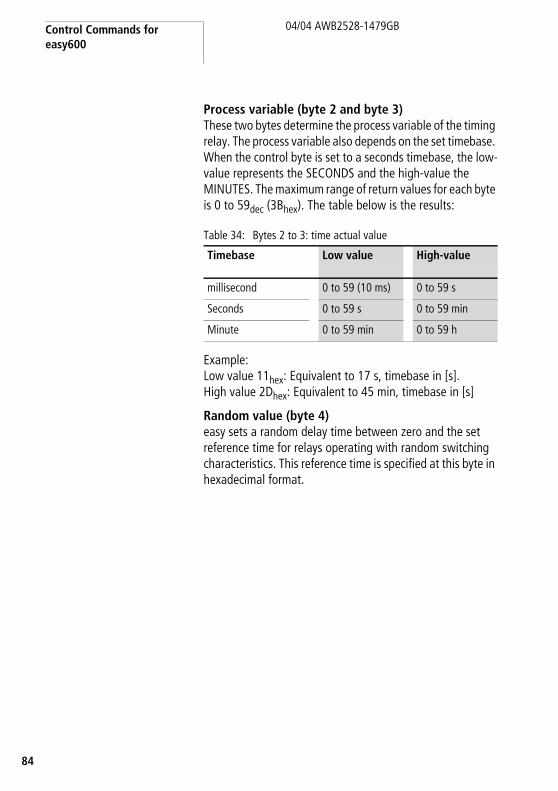
Process variable (byte 2 and byte 3)These two bytes determine the process variable of the timing relay. The process variable also depends on the set timebase. When the control byte is set to a seconds timebase, the low-value represents the SECONDS and the high-value the MINUTES. The maximum range of return values for each byte is 0 to 59dec (3Bhex). The table below is the results:
Table 34: Bytes 2 to 3: time actual value
Example:Low value 11hex: Equivalent to 17 s, timebase in [s].High value 2Dhex: Equivalent to 45 min, timebase in [s]
Random value (byte 4)easy sets a random delay time between zero and the set reference time for relays operating with random switching characteristics. This reference time is specified at this byte in hexadecimal format.
Timebase Low value High-value
millisecond 0 to 59 (10 ms) 0 to 59 s
Seconds 0 to 59 s 0 to 59 min
Minute 0 to 59 min 0 to 59 h

Read/write function blocks
5
04/04 AWB2528-1479GB
8
ExampleThe master initiates the command for reading timing relay T1:
The slave responds with the following values:
Value Set time = 0E10hex = 36003600 s = 60:00 M:S
Byte Meaning Value (hex)
Bit
7 6 5 4 3 2 1 0
0 Attribute ID: T1 2B 0 0 1 0 1 0 1 1
1 – 3 00
Byte Meaning Value (hex)
Bit
7 6 5 4 3 2 1 0
0 Response: Read successful
C2 1 1 0 0 0 0 1 0
1 Trigger coil activated, M:S time base, on-delayed, Parameter display +
l 1 0 0 0 1 0 0 0
2 Time actual value (low byte)
10 0 0 0 1 0 0 0 0
3 Time actual value (high byte)
0E 0 0 0 0 1 1 1 0

Control Commands for easy600
86
04/04 AWB2528-1479GB
Timing relays T1 – T8: write parameters(timing range, reference value, switching function)
Byte Meaning Value (hex), sent by Bit
m s Master Slave 7 6 5 4 3 2 1 0
Attribute ID: Write
T1 01 – 0 0 0 0 0 0 0 1
T2 02 – 0 0 0 0 0 0 1 0
T3 03 – 0 0 0 0 0 0 1 1
T4 04 – 0 0 0 0 0 1 0 0
T5 05 – 0 0 0 0 0 1 0 1
T6 06 – 0 0 0 0 0 1 1 0
T7 07 – 0 0 0 0 0 1 1 1
T8 08 – 0 0 0 0 1 0 0 0
0 Answer
Write successful – C1 1 1 0 0 0 0 0 1
Command rejected
– C0 1 1 0 0 0 0 0 0
0 1 Control byte: a table 35 Invalid
1 2 Low reference value
a page 89 00
2 3 High reference value
3 – 5 4 – 6 00 00
m = master
s = slave

Read/write function blocks
7
04/04 AWB2528-1479GB
8
The value range of the times and the timing relay setpoint are part of an “*.eas file”. If these values are changed, the original “*.eas file” will no longer match the file in EASY6... EASY6... .
Remember this characteristic when uploading, downloading or comparing “easy” circuit diagrams with EASY-SOFT.
When downloading from the PC the latest version of the “*.eas” is overwritten.
The comparison shows that the circuit diagrams are not identical.
Value range of the time values• “S” 00.00 to 99.99• "M:S” 00:00 to 99:59 (M = 00 to 99, S = 00 to 59)• “H:M” 00:00 to 99:59 (H = 00 to 99, M = 00 to 59)
h Time values over 60s are converted to minutes.Time values over 60 min. are converted to hours.Time values over 24 h are converted to days.
h Only the bytes reserved for the required time base should be used.

Control Commands for easy600
88
04/04 AWB2528-1479GB
Table 35: Byte 0: control byte
Example:Value 89hex = 10001001binTiming relay operates with off-delay, timebase in [s].
Meaning Bit
7 6 5 4 3 2 1 0
On-delayed, 0 0 0
off-delayed. 0 0 1
On-delayed with random switching, 0 1 0
Off-delayed with random switching, 0 1 1
Pulse shaping 1 0 0
Flashing 1 0 1
Time base “s” 0 0
Time base “M:S” 0 1
Time base “H:M” 1 0
Not used 0
Does not appear in the parameter menu 1
Appears in the parameter menu 0
Execution 1

Read/write function blocks
9
04/04 AWB2528-1479GB
8
Timing relay, setting the reference value (byte 1 and byte 2)Bytes 1 and 2 determine the reference value for the timing relay. The reference value is based on the selected timebase. When the control byte is set to seconds, the low value is based on seconds and the high value on the next higher timebase (minute). The value range for each byte in this case is 0 to 59dec (3Bhex). The table below is the results:
Example:Low value 11hex: Equivalent to 17 s, timebase in [s]high value 2Dhex: Equivalent to 45 min, timebase in [s]
Timebase Low value High-value
milliseconds 0 to 59 (10 ms) 0 to 59 s
Seconds 0 to 59 s 0 to 59 min
Minute 0 to 59 min 0 to 59 h

Control Commands for easy600
90
04/04 AWB2528-1479GB
Switching timer Ö1 – Ö4: read actual value (channel, ON time, OFF time)
Telegram structureByte Meaning Value (hex), sent by Bit
m s Master Slave 7 6 5 4 3 2 1 0
Attribute ID: Read
Ö1 channel A 4B – 0 1 0 0 1 0 1 1
Ö1 channel B 4C – 0 1 0 0 1 1 0 0
Ö1 channel C 4D – 0 1 0 0 1 1 0 1
Ö1 channel D 4E – 0 1 0 0 1 1 1 0
Ö2 channel A 4F – 0 1 0 0 1 1 1 1
Ö2 channel B 50 – 0 1 0 1 0 0 0 0
Ö2 channel C 51 – 0 1 0 1 0 0 0 1
Ö2 channel D 52 – 0 1 0 1 0 0 1 0
Ö3 channel A 53 – 0 1 0 1 0 0 1 1
Ö3 channel B 54 – 0 1 0 1 0 1 0 0
Ö3 channel C 55 – 0 1 0 1 0 1 0 1
Ö3 channel D 56 – 0 1 0 1 0 1 1 0
Ö4 channel A 57 – 0 1 0 1 0 1 1 1
Ö4 channel B 58 – 0 1 0 1 1 0 0 0
Ö4 channel C 59 – 0 1 0 1 1 0 0 1
Ö4 channel D 5A – 0 1 0 1 1 0 1 0
0 Answer
Read successful – C2 1 1 0 0 0 0 1 0
Command rejected – C0 1 1 0 0 0 0 0 0
0 1 Control byte switching timer 00 a table 36
1 2 Control byte channel 00 a table 37
2 3 Minute (switch point ON) 00 a page 93
3 4 Hour (switch point ON) 00
4 5 Minute (switch point OFF) 00
5 6 Hour (switch point OFF) 00
m = master
s = slave

Read/write function blocks
1
04/04 AWB2528-1479GB
9
Table 36: Byte 1: “switching timer” control byte
Example:Value 80hex = 10000000bin:The addressed switching timer is used in the circuit diagram.
Control byte channel(Weekday: starting/ending, parameter menu display)Each channel of a weekly switching timer is assigned a control byte that defines the start/stop conditions. The table below shows the precise structure of this control byte.
Table 37: Byte 2: “channel” control byte
Meaning Bit
7 6 5 4 3 2 1 0
Not being processed 0 0 0 0 0 0 0 0
Execution (is being processed in the circuit diagram)
1 0 0 0 0 0 0 0
Meaning Bit
7 6 5 4 3 2 1 0
Day ON
No day set 0 0 0
Monday 0 0 1
Tuesday 0 1 0
Wednesday 0 1 1
Thursday 1 0 0
Friday 1 0 1
Saturday 1 1 0
Sunday 1 1 1

Control Commands for easy600
92
04/04 AWB2528-1479GB
Example:Value 31hex = 00110001bin:The previously selected channel X of weekly timer Y is active Monday through Saturday.
Day OFF
No day set 0 0 0
Monday 0 0 1
Tuesday 0 1 0
Wednesday 0 1 1
Thursday 1 0 0
Friday 1 0 1
Saturday 1 1 0
Sunday 1 1 1
Appears in the parameter menu
No 1 0
Yes 0 0
Meaning Bit
7 6 5 4 3 2 1 0

Read/write function blocks
3
04/04 AWB2528-1479GB
9
Switching times (byte 3 to byte 6)The table below shows which bytes precisely determine the ON and OFF times of a channel. The resolution is in seconds.
Example:
ON time OFF time
Byte 3: Byte 4: Byte 5: Byte 6:
MinuteON
HourON
MinuteOFF
HourOFF
00 to 3Bhex (00 to 59dec)
00 to 17hex (00 to 23dec)
00 to 3Bhex (00 to 59dec)
00 to 17hex (00 to 23dec)
h "easy" returns hexadecimal values. You may have to convert the corresponding values into decimal format.
Byte Value Description
0 42hex The read request has been executed. Data follow.
1 80hex The addressed switching timer is used in the circuit diagram.
2 31hex(see above)
Day: Monday through SaturdayThe channel appears in the parameter menu
3 00hex ON 19:00
4 13hex
5 1Ehex OFF: 06:30
6 06hex

Control Commands for easy600
94
04/04 AWB2528-1479GB
Switching timer Ö1 – Ö4: read setpoint value (channel, ON time, OFF time)
Telegram structureByte Meaning Value (hex), sent by Bit
m s Master Slave 7 6 5 4 3 2 1 0
Instruction
Ö1 channel A 12 – 0 0 0 1 0 0 1 0
Ö1 channel B 13 – 0 0 0 1 0 0 1 1
Ö1 channel C 14 – 0 0 0 1 0 1 0 0
Ö1 channel D 15 – 0 0 0 1 0 1 0 1
Ö2 channel A 16 – 0 0 0 1 0 1 1 0
Ö2 channel B 17 – 0 0 0 1 0 1 1 1
Ö2 channel C 18 – 0 0 0 1 1 0 0 0
Ö2 channel D 19 – 0 0 0 1 1 0 0 1
Ö3 channel A 1A – 0 0 0 1 1 0 1 0
Ö3 channel B 1B – 0 0 0 1 1 0 1 1
Ö3 channel C 1C – 0 0 0 1 1 1 0 0
Ö3 channel D 1D – 0 0 0 1 1 1 0 1
Ö4 channel A 1E – 0 0 0 1 1 1 1 0
Ö4 channel B 1F – 0 0 0 1 1 1 1 1
Ö4 channel C 20 – 0 0 1 0 0 0 0 0
Ö4 channel D 21 – 0 0 1 0 0 0 0 1
0 Answer
Write successful – C1 1 1 0 0 0 0 0 1
Command rejected – C0 1 1 0 0 0 0 0 0
0 1 Control byte (day begin/end)
a page 95 00
1 2 Minute (switch point ON) a page 97 00
2 3 Hour (switch point ON) 00
3 4 Minute (switch point OFF) 00
4 5 Hour (switch point OFF) 00
5 6 Not used
m = master
s = slave

Read/write function blocks
5
04/04 AWB2528-1479GB
9
Remember this feature when uploading, downloading or comparing “easy” circuit diagrams with EASY-SOFT. When downloading from the PC the latest version of the “*.eas” is overwritten. The comparison shows that the circuit diagrams are not identical.
Control byte (Weekday: starting/ending, parameter menu display)Each channel of a weekly timer is assigned a control byte that defines the start/stop conditions. The table below shows the precise structure of this control byte.
Table 38: Byte 0: control byte
h Keep within the value range: The values for minute and hour of the respective switching points are components of an EASY-SOFT file (*.eas). If these values are changed, the original “*.eas file” will no longer match the file in EASY6... .
Meaning Bit
7 6 5 4 3 2 1 0
Day ON
No day set 0 0 0
Monday 0 0 1
Tuesday 0 1 0
Wednesday 0 1 1
Thursday 1 0 0
Friday 1 0 1
Saturday 1 1 0
Sunday 1 1 1

Control Commands for easy600
96
04/04 AWB2528-1479GB
Example:Value 31hex = 00110001bin:The previously selected channel X of weekly timer Y is active Monday through Saturday.
Day OFF
No day set 0 0 0
Monday 0 0 1
Tuesday 0 1 0
Wednesday 0 1 1
Thursday 1 0 0
Friday 1 0 1
Saturday 1 1 0
Sunday 1 1 1
Appears in the parameter menu
No 1 0
Yes 0 0
Meaning Bit
7 6 5 4 3 2 1 0
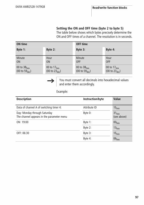
Read/write function blocks
7
04/04 AWB2528-1479GB
9
Setting the ON and OFF time (byte 2 to byte 5)The table below shows which bytes precisely determine the ON and OFF times of a channel. The resolution is in seconds.
Example:
ON time OFF time
Byte 1: Byte 2: Byte 3: Byte 4:
MinuteON
HourON
MinuteOFF
HourOFF
00 to 3Bhex (00 to 59dec)
00 to 17hex (00 to 23dec)
00 to 3Bhex (00 to 59dec)
00 to 17hex (00 to 23dec)
h You must convert all decimals into hexadecimal values and enter them accordingly.
Description Instruction/byte Value
Data of channel A of switching timer 4: Attribute ID 1Ehex
Day: Monday through SaturdayThe channel appears in the parameter menu
Byte 0: 31hex(see above)
ON 19:00 Byte 1: 00hex
Byte 2: 13hex
OFF: 06:30 Byte 3: 1Ehex
Byte 4: 06hex
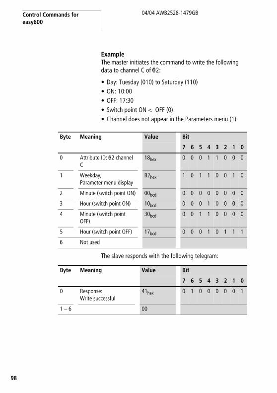
Control Commands for easy600
98
04/04 AWB2528-1479GB
ExampleThe master initiates the command to write the following data to channel C of Ö2:
• Day: Tuesday (010) to Saturday (110)• ON: 10:00• OFF: 17:30• Switch point ON < OFF (0)• Channel does not appear in the Parameters menu (1)
The slave responds with the following telegram:
Byte Meaning Value Bit
7 6 5 4 3 2 1 0
0 Attribute ID: Ö2 channel C
18hex 0 0 0 1 1 0 0 0
1 Weekday,Parameter menu display
B2hex 1 0 1 1 0 0 1 0
2 Minute (switch point ON) 00bcd 0 0 0 0 0 0 0 0
3 Hour (switch point ON) 10bcd 0 0 0 1 0 0 0 0
4 Minute (switch point OFF)
30bcd 0 0 1 1 0 0 0 0
5 Hour (switch point OFF) 17bcd 0 0 0 1 0 1 1 1
6 Not used
Byte Meaning Value Bit
7 6 5 4 3 2 1 0
0 Response:
Write successful41hex 0 1 0 0 0 0 0 1
1 – 6 00

9
10/04 AWB2528-1427GB
9
7 Control commands for easy700
Control commands can be used to initiate data exchange for special services:
• „Read/write date and time“ (page 101)• „Read/write image data“ (page 105)• „Read/write function block data“ (page 126).
The master PLC in this case falls back upon the message transfer protocol of the explicit messages. All parameters are addressed via the Service Code 32hex. The assigned attribute ID is here used to distinguish between different parameters.
A data exchange procedure is required in order to ensure the safe exchange of data via DeviceNet from master to slave and vice versa.
Service code Object address
Class ID Instance ID
32hex 64hex 01hex
h Note!The I/O data retain their previously defined state while a control command is being executed. The I/O data will not be updated until data exchange for the control command has been terminated.
i Caution!You may use only the values specified for the instruction code.Verify data to be transferred in order to avoid unnecessary errors.
h The operating mode of the basic unit must correspond with the status indicated at the LEDs when the various parameters are being set.

Control commands for easy700
100
10/04 AWB2528-1427GB
The master transmits a control command to initiate data exchange between the communication partners. The slave always returns an answer to this request, which indicates whether data has been exchanged or not. An error code will be returned if data exchange has failed. This code is precisely defined in the ODVA specifications a section “References”, page 8.

Read/write date and time
01
10/04 AWB2528-1427GB
1
Read/write date and time
Telegram structure
h Please also note the relevant description of the real-time clock provided in the easy700 manual (AWB2528-1508GB).
Byte Meaning Value (hex), sent by
m s Master Slave
Attribute ID
Read 93 –
Write B3 –
0 Answer
Read successful – C2
Write successful – C1
Command rejected – C0
0 1 Len 05 05
1 2 Index 0 – 21 0 – 21
2 – 6 3 – 7 Data 1 – 5 depending on index, a table 39
depending on index,a table 39
1) 0 = Time/date, a table 391 = Summer time, a table 402 = Winter time, a table 41
m = Master
s = slave

Control commands for easy700
102
10/04 AWB2528-1427GB
Table 39: Index 0 – date and time of real-time clock
Table 40: Index 1 – Summer time
Byte Content Operand Value (hex)
Master Slave
2 3 Data 1 Hour 0 to 23 0x00 to 0x17h
3 4 Data 2 Minute 0 to 59 0x00 to 0x3Bh
4 5 Data 3 Day Day (1 to 28; 29, 30, 31; depending on month and year)
0x01 to 0x1Fh
5 6 Data 4 Month 1 to 12 0x01 to 0x0Ch
6 7 Data 5 Year 0 to 99 (corresponds to 2000-2099)
0x00 to 0x63h
Byte Content Value (hex)
Master Slave
2 3 Data 1 Area
None 00
Rule 01
Automatic EU 02
Automatic GB 03
Automatic US 04
for “Area” = “Rule”:
3 4 Data 2 Summer time switching rule
a table 42
4 5 Data 3
5 6 Data 4
6 7 Data 5

Read/write date and time
03
10/04 AWB2528-1427GB
1
Table 41: Index 2 – Winter time (only valid if Area = “Rule” selected)
Switching rule bit array
Byte Content Value (hex)
Master Slave
2 3 Data 1 Area = Rule 01
3 – 6 4 – 7 Data 2 – 5 Winter time switching rule
a table 42
h Please also read the detailed description in the easy700 manual (AWB2528-1508GB).
The following table shows the composition of the corresponding data bytes.
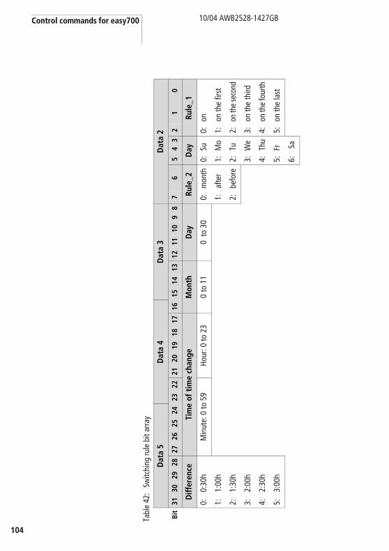
Control commands for easy700
104
10/04 AWB2528-1427GB
Tabl
e 42
:Sw
itchi
ng ru
le b
it ar
ray
Dat
a 5
Dat
a 4
Dat
a 3
Dat
a 2
Bit
3130
2928
2726
2524
2322
2120
1918
1716
1514
1312
1110
98
76
54
32
10
Diff
eren
ceTi
me
of t
ime
chan
geM
onth
Day
Rule
_2D
ayRu
le_1
0:0:
30h
Min
ute:
0 to
59
Hour
: 0 to
23
0 to
11
0 to
30
0:m
onth
0:Su
0:on
1:1:
00h
1:af
ter
1:M
o1:
on th
e fir
st
2:1:
30h
2:be
fore
2:Tu
2:on
the
seco
nd
3:2:
00h
3:W
e3:
on th
e th
ird
4:2:
30h
4:Th
u4:
on th
e fo
urth
5:3:
00h
5:Fr
5:on
the
last
6:Sa

Read/write image data
05
10/04 AWB2528-1427GB
1
Read/write image data
Overview
h Please also observe the relevant description of possible image data provided in the easy700 manual (AWB2528-1508GB) or in the EASY-SOFT Help. The information provided in section “General notes on working with image data” on page 61 also applies to easy700.
Operands Meaning Read/Write Type (hex)
Page
A1 – A16 „Analog value comparators/threshold comparators: A1 – A16“
read 8B 106
C1 – C16 „Counters: C1 – C16“ read EE 107
D1 – D16 „Text function blocks: D1 – D16“ read 94 108
I1 – I16 „Local inputs: I1 – I16“ read 84 109
IA1 – IA4 „Local analog inputs: IA1 – IA4“ read 8C 110
M1 – M16, N1 – N16
„Write marker: M1 – M16/N1 – N16“ write 86/87 112
M1 – M16, N1 – N16
„Read marker: M1 – M16/N1 – N16“ read 86/87 114
O1 – O4 „Operating hours counters: O1 – O4“ read EF 116
P1 – P4 „Local P buttons: P1 – P4“ read 8A 117
Q1 – Q8 „Local outputs: Q1 – Q8“ read 85 119
R1 – R16/S1 – S8
„Inputs/outputs of EASY-LINK: R1 –R16/S1 – S8“
read 88/89 120
T1 – T16 „Timers: T1 – T16“ read ED 122
Y1 – Y4 „Year time switch: Y1 – Y8“ read 91 123
Z1 – Z3 „Master reset: Z1 – Z3“ read 93 124
H1 – H4 7-day time switch: Ö1 – Ö8 read 90 125

Control commands for easy700
106
10/04 AWB2528-1427GB
Analog value comparators/threshold comparators: A1 – A16
The following commands are used to read the logic state of the individual analog value comparators A1 to A16.
Telegram structure
Table 43: Byte 3 to 4 (master) or Byte 4 to 5 (slave): Data 1 to 2
Byte Meaning Value (hex), sent by
Master Slave Master Slave
Attribute ID: Read 88 –
0 Response:
Read successful – C2
Command rejected
– C01
0 1 Len 01 01
1 2 Type 8B 8B
2 3 Index 00 00
3 4 Data 1 (Low Byte) 00 a table 43
4 5 Data 2 (Low Byte) 00 a table 43
5 – 6 6 – 7 Data 3 – 4 00 00
1) Possible causes a page 144
Data 1 Bit 7 6 5 4 3 2 1 0
A1 0/1
A2 0/1
... ...
A8 0/1
Data 2 Bit 7 6 5 4 3 2 1 0
A9 0/1
A10 0/1
... ...
A16 0/1
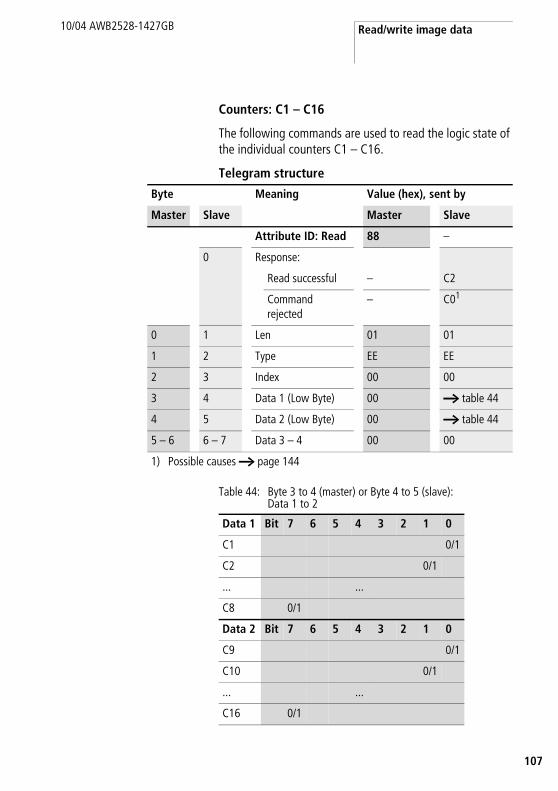
Read/write image data
07
10/04 AWB2528-1427GB
1
Counters: C1 – C16
The following commands are used to read the logic state of the individual counters C1 – C16.
Telegram structure
Table 44: Byte 3 to 4 (master) or Byte 4 to 5 (slave): Data 1 to 2
Byte Meaning Value (hex), sent by
Master Slave Master Slave
Attribute ID: Read 88 –
0 Response:
Read successful – C2
Command rejected
– C01
0 1 Len 01 01
1 2 Type EE EE
2 3 Index 00 00
3 4 Data 1 (Low Byte) 00 a table 44
4 5 Data 2 (Low Byte) 00 a table 44
5 – 6 6 – 7 Data 3 – 4 00 00
1) Possible causes a page 144
Data 1 Bit 7 6 5 4 3 2 1 0
C1 0/1
C2 0/1
... ...
C8 0/1
Data 2 Bit 7 6 5 4 3 2 1 0
C9 0/1
C10 0/1
... ...
C16 0/1
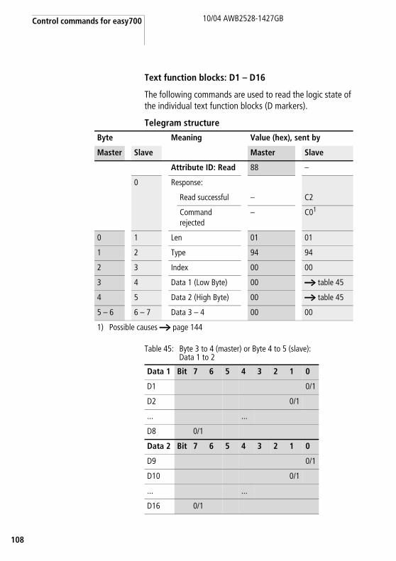
Control commands for easy700
108
10/04 AWB2528-1427GB
Text function blocks: D1 – D16
The following commands are used to read the logic state of the individual text function blocks (D markers).
Telegram structure
Table 45: Byte 3 to 4 (master) or Byte 4 to 5 (slave): Data 1 to 2
Byte Meaning Value (hex), sent by
Master Slave Master Slave
Attribute ID: Read 88 –
0 Response:
Read successful – C2
Command rejected
– C01
0 1 Len 01 01
1 2 Type 94 94
2 3 Index 00 00
3 4 Data 1 (Low Byte) 00 a table 45
4 5 Data 2 (High Byte) 00 a table 45
5 – 6 6 – 7 Data 3 – 4 00 00
1) Possible causes a page 144
Data 1 Bit 7 6 5 4 3 2 1 0
D1 0/1
D2 0/1
... ...
D8 0/1
Data 2 Bit 7 6 5 4 3 2 1 0
D9 0/1
D10 0/1
... ...
D16 0/1

Read/write image data
09
10/04 AWB2528-1427GB
1
Local inputs: I1 – I16
This command string enables you to read the local inputs of the easy700 basic unit. The relevant input word is stored in Intel format.
Telegram structure
Table 46: Byte 3 to 4 (master) or Byte 4 to 5 (slave): Data 1 to 2
Byte Meaning Value (hex), sent by
Master Slave Master Slave
Attribute ID: Read 88 –
0 Response:
Read successful – C2
Command rejected
– C01)
0 1 Len 02 02
1 2 Type 84 84
2 3 Index 00 00
3 4 Data 1 (Low Byte) 00 a table 46
4 5 Data 2 (High Byte) 00 a table 46
5 – 6 6 – 7 Data 3 – 4 00 00
1) Possible causes a page 144
Data 1 Bit 7 6 5 4 3 2 1 0
I1 0/1
I2 0/1
.. ..
I8 0/1
Data 2 Bit 7 6 5 4 3 2 1 0
I9 0/1
I10 0/1
.. ..
I16 0/1

Control commands for easy700
110
10/04 AWB2528-1427GB
Local analog inputs: IA1 – IA4
The analog inputs on the easy700 basic unit (I7, I8, I11, I12) can be read directly via DeviceNet. The 16-bit value is transferred in Intel format (Low Byte first).
Telegram structure
Byte Meaning Value (hex), sent by
Master Slave Master Slave
Attribute ID: Read 88 –
0 Response:
Read successful – C2
Command rejected
– C01
0 1 Len 02 02
1 2 Type 8C 8C
2 3 Index 00 – 032 00 – 032
3 4 Data 1 (Low Byte) 00 a table 47
4 5 Data 2 (High Byte) 00 a table 47
5 – 6 6 – 7 Data 3 – 4 00 00
1) Possible causes a page 1442) 00 = Analog input I7
01 = Analog input I802 = Analog input I1103 = Analog input I12

Read/write image data
11
10/04 AWB2528-1427GB
1
Example:A voltage signal is present at analog input 1. The required telegrams for reading the analog value are as follows:
Table 47: Example telegram for reading the value at the analog input
Byte 4 – Data 1 (Low Byte): 4BhexByte 5 – Data 2 (High Byte): 03hexl corresponding 16-bit value: 034Bhex = 843
The value 843 corresponds to the 10 bit value of the analog converter. The following conversion is required for the actual analog value:
Byte Meaning Value (hex), sent by
Master Slave Master Slave
Attribute ID: Read 88 –
0 Response: read successful – C2
0 1 Len 02 02
1 2 Type 8C 8C
2 3 Index 021 021
3 4 Data 1 00 4B
4 5 Data 2 00 03
5 6 Data 3 00 00
6 7 Data 4 00 00
1) 02 = Analog input I11
10 Vx 10 bit =>
10 Vx 843 = 8.24 V
1023 1023

Control commands for easy700
112
10/04 AWB2528-1427GB
Write marker: M1 – M16/N1 – N16
Telegram structure
Byte Meaning Value (hex), sent by
Master Slave Master Slave
Attribute ID: Write 8C –
0 Response:
Write successful – C1
Command rejected – C01
0 1 Len 01 01
1 2 Type2
With M marker 86 86
With N marker 87 87
2 3 Index2 00 – 0F 00 – 0F
3 4 Data 1 (Low Byte)3 00/01 00/01
4 – 6 5 – 7 Data 2 – 4 00 00
1) Possible causes a page 1442) There are 16 M markers and 16 N markers. The markers are addressed by Type
and Index:Use Type to select the M or N marker. Use Index to select the marker number.
3) The marker is set if a value is written to the data byte that does not equal zero. The marker is reset accordingly if the value 0 is written to data byte Data 1.

Read/write image data
13
10/04 AWB2528-1427GB
1
Example:Marker M13 is set.
Byte Meaning Value (hex), sent by
Master Slave Master Slave
Attribute ID: Write 8C –
0 Response:
Write successful – C1
Command rejected – C01
0 1 Len 01 01
1 2 Type
M marker 86 86
2 3 Index 0C 0C
3 4 Data 1 01 00
4 – 6 5 – 7 Data 2 – 4 00 00
1) Possible causes a page 144

Control commands for easy700
114
10/04 AWB2528-1427GB
Read marker: M1 – M16/N1 – N16
Unlike the write operation, the marker read operation reads the entire marker area of a particular marker type (M or N) is read.
Telegram structure
Byte Meaning Value (hex), sent by
Master Slave Master Slave
Attribute ID: Read 88 –
0 Response:
Read successful – C2
Command rejected
– C01
0 1 Len 01 01
1 2 Type
M marker 86 86
N marker 87 87
2 3 Index2 00 00
3 4 Data 1 (Low Byte) 00 a table 48
4 5 Data 2 (Low Byte) 00 a table 48
5 – 6 6 – 7 Data 3 – 4 00 00
1) Possible causes a page 1442) There are 16 M markers and 16 N markers. The markers are addressed by
Type and Index:Use Type to select the M or N marker. Use Index to select the marker number.

Read/write image data
15
10/04 AWB2528-1427GB
1
Table 48: Byte 3 to 4 (master) or Byte 4 to 5 (slave): Data 1 to 2
Example: The N markers are read:
The markers N3, N11 and N16 are set.
Data 1 Bit 7 6 5 4 3 2 1 0
m N
M1 N1 0/1
M2 N2 0/1
... ... ...
M8 N8 0/1
Data 2 Bit 7 6 5 4 3 2 1 0
M9 N9 0/1
M10 N10 0/1
... – ...
M16 N16 0/1
Byte Meaning Value (hex), sent by
Master Slave Master Slave
Attribute ID: Read 88 –
0 Response:
Read successful
– C2
Command rejected
– C01
0 1 Len 01 01
1 2 Type
N marker 87 87
2 3 Index 00 00
3 4 Data 1 (Low Byte) 00 04
4 5 Data 2 (Low Byte) 00 84
5 – 6 6 – 7 Data 3 – 4 00 00
1) Possible causes a page 144

Control commands for easy700
116
10/04 AWB2528-1427GB
Operating hours counters: O1 – O4
The following commands are used to read the logic state of the operating hours counters O1 – O4.
Telegram structure
Table 49: Byte 3 (master) or byte 4 (slave): Data 1
Byte Meaning Value (hex), sent by
Master Slave Master Slave
Attribute ID: Read 88 –
0 Response:
Read successful – C2
Command rejected
– C01
0 1 Len 01 01
1 2 Type EF EF
2 3 Index 00 00
3 4 Data 1 (Low Byte) 00 a table 49
4 – 6 5 – 7 Data 2 – 4 00 00
1) Possible causes a page 144
Data 1 Bit 7 6 5 4 3 2 1 0
O1 0/1
O2 0/1
O3 0/1
O4 0/1
... ... ... ... ...
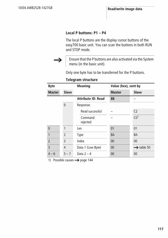
Read/write image data
17
10/04 AWB2528-1427GB
1
Local P buttons: P1 – P4
The local P buttons are the display cursor buttons of the easy700 basic unit. You can scan the buttons in both RUN and STOP mode.
Only one byte has to be transferred for the P buttons.
Telegram structure
h Ensure that the P buttons are also activated via the System menu (in the basic unit).
Byte Meaning Value (hex), sent by
Master Slave Master Slave
Attribute ID: Read 88 –
0 Response:
Read successful – C2
Command rejected
– C01
0 1 Len 01 01
1 2 Type 8A 8A
2 3 Index 00 00
3 4 Data 1 (Low Byte) 00 a table 50
4 – 6 5 – 7 Data 2 – 4 00 00
1) Possible causes a page 144
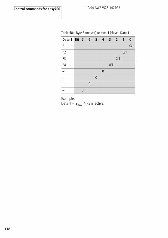
Control commands for easy700
118
10/04 AWB2528-1427GB
Table 50: Byte 3 (master) or byte 4 (slave): Data 1
Example:Data 1 = 2hex l P3 is active.
Data 1 Bit 7 6 5 4 3 2 1 0
P1 0/1
P2 0/1
P3 0/1
P4 0/1
– 0
– 0
– 0
– 0

Read/write image data
19
10/04 AWB2528-1427GB
1
Local outputs: Q1 – Q8
The local outputs can be read directly via the DeviceNet fieldbus.
Telegram structure
Table 51: Byte 4: Data 1
Example:Data 1 = 52hex l Q2, Q5 and Q7 are active.
Byte Meaning Value (hex), sent by
Master Slave Master Slave
Attribute ID: Read 88 –
0 Response:
Read successful – C2
Command rejected
– C01)
0 1 Len 01 01
1 2 Type 85 85
2 3 Index 00 00
3 4 Data 1 (Low Byte) 00 a table 51
4 – 6 5 – 7 Data 2 – 4 00 00
1) Possible causes a page 144
Data 1 Bit 7 6 5 4 3 2 1 0
Q1 0/1
Q2 0/1
.. ..
Q8 0/1

Control commands for easy700
120
10/04 AWB2528-1427GB
Inputs/outputs of EASY-LINK: R1 – R16/S1 – S8
This service allows you to read the local R and S data and the data of the NET stations (1 – 8) transferred via EASYLINK, again from the relevant easy700 image.
Telegram structure
Byte Meaning Value (hex), sent by
Master Slave Master Slave
Attribute ID: Read 88 –
0 Response:
Read successful – C2
Command rejected
– C01)
0 1 Len 01 01
1 2 Type
for R data 88 88
for S data 89 89
2 3 Index 00 00
3 4 Data 1 (Low Byte) 00 a table 52
4 5 Data 2 (Low Byte) 00 a table 52
5 – 6 6 – 7 Data 3 – 4 00 00
1) Possible causes a page 144

Read/write image data
21
10/04 AWB2528-1427GB
1
Table 52: Byte 3 to 4 (master) or Byte 4 to 5 (slave): Data 1 to 2
Data 1 Bit 7 6 5 4 3 2 1 0
RW SW
R1 S1 0/1
R2 S2 0/1
... ... ...
R8 S8 0/1
Data 2 Bit 7 6 5 4 3 2 1 0
R9 – 0/1
R10 – 0/1
... – ...
R16 – 0/1

Control commands for easy700
122
10/04 AWB2528-1427GB
Timers: T1 – T16
The following commands are used to read the logic state of the individual timers T1 - T16.
Telegram structure
Table 53: Byte 3 to 4 (master) or Byte 4 to 5 (slave): Data 1 to 2
Byte Meaning Value (hex), sent by
Master Slave Master Slave
Attribute ID: Read 88 –
0 Response:
Read successful – C2
Command rejected
– C01
0 1 Len 01 01
1 2 Type ED ED
2 3 Index 00 00
3 4 Data 1 (Low Byte) 00 a table 53
4 5 Data 2 (Low Byte) 00 a table 53
5 – 6 6 – 7 Data 3 – 4 00 00
1) Possible causes a page 144
Data 1 Bit 7 6 5 4 3 2 1 0
T1 0/1
T2 0/1
... ...
T8 0/1
Data 2 Bit 7 6 5 4 3 2 1 0
T9 0/1
T10 0/1
... ...
T16 0/1
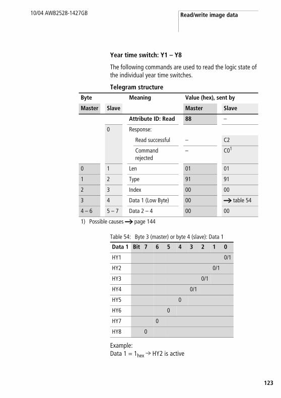
Read/write image data
23
10/04 AWB2528-1427GB
1
Year time switch: Y1 – Y8
The following commands are used to read the logic state of the individual year time switches.
Telegram structure
Table 54: Byte 3 (master) or byte 4 (slave): Data 1
Example:Data 1 = 1hex l HY2 is active
Byte Meaning Value (hex), sent by
Master Slave Master Slave
Attribute ID: Read 88 –
0 Response:
Read successful – C2
Command rejected
– C01
0 1 Len 01 01
1 2 Type 91 91
2 3 Index 00 00
3 4 Data 1 (Low Byte) 00 a table 54
4 – 6 5 – 7 Data 2 – 4 00 00
1) Possible causes a page 144
Data 1 Bit 7 6 5 4 3 2 1 0
HY1 0/1
HY2 0/1
HY3 0/1
HY4 0/1
HY5 0
HY6 0
HY7 0
HY8 0

Control commands for easy700
124
10/04 AWB2528-1427GB
Master reset: Z1 – Z3
Telegram structure
Table 55: Byte 3 (master) or byte 4 (slave): Data 1
Byte Meaning Value (hex), sent by
Master Slave Master Slave
Attribute ID: Read 88 –
0 Response:
Read successful – C2
Command rejected – C01
0 1 Len 01 01
1 2 Type 93 93
2 3 Index 00 00
3 4 Data 1 (Low Byte) 00 a table 55
4 – 6 5 – 7 Data 2 – 4 00 00
1) Possible causes a page 144
Data 1 Bit 7 6 5 4 3 2 1 0
Z1 for Q outputs 0/1
Z2 for M markers 0/1
Z3 for outputs and markers
0/1
... 0 0 0 0 0

Read/write image data
25
10/04 AWB2528-1427GB
1
7-day time switch: ö1 – ö8
The following commands are used to read the logic state of the individual 7-day time switches.
Telegram structure
Table 56: Byte 3 (master) or byte 4 (slave): Data 1
Example:Data 1 = 2hex l ö3 is active.
Byte Meaning Value (hex), sent by
Master Slave Master Slave
Attribute ID: Read 88 –
0 Response:
Read successful – C2
Command rejected
– C01
0 1 Len 01 01
1 2 Type 90 90
2 3 Index 00 00
3 4 Data 1 (Low Byte) 00 a table 56
4 – 6 5 – 7 Data 2 – 4 00 00
1) Possible causes a page 144
Data 1 Bit 7 6 5 4 3 2 1 0
HW1 0/1
HW2 0/1
HW3 0/1
HW4 0/1
HW5 0
HW6 0
HW7 0
HW8 0

Control commands for easy700
126
10/04 AWB2528-1427GB
Read/write function block data
General notes
Always note the following when working with function blocks:
• The relevant data is transferred in Intel format. In other words, the first byte is the low byte (Byte 5) and the last byte (byte 8) the high byte.
• The maximum data length is 4 bytes. All values must be transferred in hexadecimal format.
Overview
h Please also observe the relevant description of the function blocks provided in the easy700 manual (AWB2528-1508GB) or in the EASY-SOFT Help.
Operands Meaning Read/Write Type(hex)
Page
A1 – A16 „Analog value comparator/threshold comparator: A1 – A16“
Read/Write 8D 127
C1 – C16 „Counter relays: C1 – C16“ Read/Write 8F 130
O1 – O4 „Operating hours counters: O1 – O4“ Read/Write 92 133
T1 – T16 „Timing relays: T1 – T16“ Read/Write 8E 135
Y1 – Y8 „Year time switch: Y1 – Y8“ Read/Write A2 138
Ö1 – Ö8 7-day time switch: Ö1 – Ö8 Read/Write A1 141

Read/write function block data
27
10/04 AWB2528-1427GB
1
Analog value comparator/threshold comparator: A1 – A16
Telegram structure
Byte Meaning Value (hex), sent by
Master Slave Master Slave
Attribute ID
Read 89 –
Write 8D –
0 Response:
Read successful – C2
Write successful – C1
Command rejected
– C01
0 1 Type 8D 8D
1 2 Instance2 00 – 0F 00 – 0F
2 3 Index a table 57 a table 57
3 – 6 4 – 7 Data 1 – 4 depending on index,a table 58
depending on index,a table 58
1) Possible causes a page 1442) easy provides 16 analog comparators A1 to A16 for use as required. These can be
addressed using the instance (0 – F).
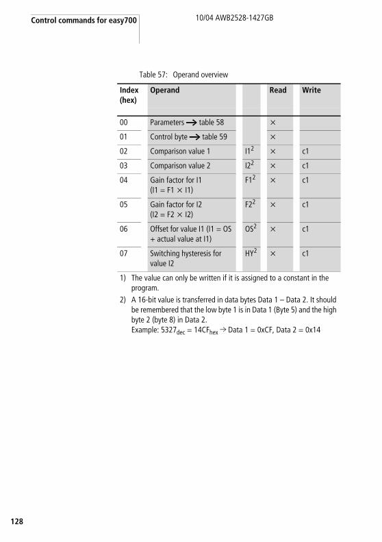
Control commands for easy700
128
10/04 AWB2528-1427GB
Table 57: Operand overview
Index (hex)
Operand Read Write
00 Parameters a table 58 x
01 Control byte a table 59 x
02 Comparison value 1 I12 x c1
03 Comparison value 2 I22 x c1
04 Gain factor for I1(I1 = F1 x I1)
F12 x c1
05 Gain factor for I2 (I2 = F2 x I2)
F22 x c1
06 Offset for value I1 (I1 = OS + actual value at I1)
OS2 x c1
07 Switching hysteresis for value I2
HY2 x c1
1) The value can only be written if it is assigned to a constant in the program.
2) A 16-bit value is transferred in data bytes Data 1 – Data 2. It should be remembered that the low byte 1 is in Data 1 (Byte 5) and the high byte 2 (byte 8) in Data 2.Example: 5327dec = 14CFhex l Data 1 = 0xCF, Data 2 = 0x14
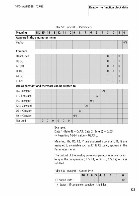
Read/write function block data
29
10/04 AWB2528-1427GB
1
Table 58: Index 00 – Parameters
Example: Data 1 (Byte 4) = 0xA3, Data 2 (Byte 5) = 0x03 l Resulting 16-bit value = 03A3hex
Meaning: HY, OS, F2, F1 are assigned a constant; I1, I2 are assigned to a variable such as I7, I8 C2...etc., appears in the Parameter menu;
The output of the analog value comparator is active for as long as the comparison (I1 x F1) + OS = (I2 x F2) + HY is fulfilled.
Table 59: Index 01 – Control byte
Meaning Bit 15 14 13 12 11 10 9 8 7 6 5 4 3 2 1 0
Appears in the parameter menu
Yes/no 0/1
Compare
FB not used 0 0 0
EQ (=) 0 0 1
GE (f) 0 1 0
LE (F) 0 1 1
GT (>) 1 0 0
LT (<) 1 0 1
Use as constant and therefore can be written to
I1= Constant 0/1
F1= Constant 0/1
I2= Constant 0/1
F2 = Constant 0/1
OS = Constant 0/1
HY = Constant 0/1
Not used 0 0 0 0 0 0
Bit 7 6 5 4 3 2 1 0
FB output Data 3 – – – – – – – Q11
1) Status 1 if comparison condition is fulfilled.
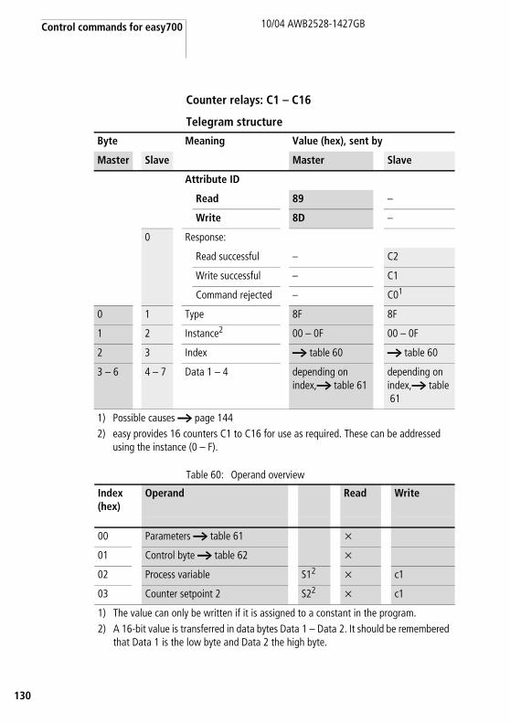
Control commands for easy700
130
10/04 AWB2528-1427GB
Counter relays: C1 – C16
Telegram structure
Table 60: Operand overview
Byte Meaning Value (hex), sent by
Master Slave Master Slave
Attribute ID
Read 89 –
Write 8D –
0 Response:
Read successful – C2
Write successful – C1
Command rejected – C01
0 1 Type 8F 8F
1 2 Instance2 00 – 0F 00 – 0F
2 3 Index a table 60 a table 60
3 – 6 4 – 7 Data 1 – 4 depending on index,a table 61
depending on index,a table61
1) Possible causes a page 1442) easy provides 16 counters C1 to C16 for use as required. These can be addressed
using the instance (0 – F).
Index (hex)
Operand Read Write
00 Parameters a table 61 x
01 Control byte a table 62 x
02 Process variable S12 x c1
03 Counter setpoint 2 S22 x c1
1) The value can only be written if it is assigned to a constant in the program.2) A 16-bit value is transferred in data bytes Data 1 – Data 2. It should be remembered
that Data 1 is the low byte and Data 2 the high byte.

Read/write function block data
31
10/04 AWB2528-1427GB
1
Table 61: Index 00 – Parameters
Example:Data 1 (Byte 4) = 0x07
Meaning:The values appear in the Parameter menu. The counter is used in the mode of the frequency meter. The counter setpoint 1 is not assigned to a constant and cannot therefore be written to.
Table 62: Index 01 – Control byte
Meaning Bit 7 6 5 4 3 2 1 0
Appears in the parameter menu
Yes/no 0/1
Counter mode
FB not used 0 0
Up/down counter (N) 0 1
High-speed up/down counter (H) 1 0
Frequency counter (F) 1 1
Use as constant and therefore can be written to
Counter setpoint S1 0/1
Unused bits – – – –
Data 1 Bit 7 6 5 4 3 2 1 0
FB output – – – – C4 RE3 D2 Q11
1) Switch contact 2) Count direction: 0 = up counting,
1 = down counting3) Reset, the timing relay is reset (reset coil)4) Count coil, counts on every rising edge

Control commands for easy700
132
10/04 AWB2528-1427GB
Example:the actual value of C3 is to be read:
Explanation:
Data 1 = 12Data 2 = 03l resulting 16-bit value = 0312hex = 786dec
Counter status = 786
Byte Meaning Value (hex), sent by
Master Slave Master Slave
Command: Read 89 –
0 Response: read successful
– C2
0 1 Type 8F 8F
1 2 Instance 02 02
2 3 Index 02 02
3 4 Data1 00 12
4 5 Data 2 00 03
5 6 Data 3 00 00
6 7 Data 4 00 00

Read/write function block data
33
10/04 AWB2528-1427GB
1
Operating hours counters: O1 – O4
Telegram structure
Table 63: Operand overview
Byte Meaning Value (hex), sent by
Master Slave Master Slave
Attribute ID
Read 89 –
Write 8D –
0 Response:
Read successful – C2
Write successful – C1
Command rejected – C01
0 1 Type 92 92
1 2 Instance2 00 – 03 00 – 03
2 3 Index a table 63 a table 63
3 – 6 4 – 7 Data 1 – 4 depending on index,a table 64
depending on index,a table 64
1) Possible causes a page 1442) easy provides 4 operating hours counters O1 to O4. These can be addressed using the
instance (0 – 3).
Index (hex)
Operand Read Write
00 Parameters a table 64 x
01 Control byte a table 65 x
02 Process variable S12 x c1
03 Counter setpoint 2 S22 x c1
1) The value can only be written if it is assigned to a constant in the program.
2) A 32-bit value is transferred in data bytes Data 1 – Data 4. It should be remembered that the Data 1 is the low byte and Data 4 the high byte.

Control commands for easy700
134
10/04 AWB2528-1427GB
Table 64: Index 00 – Parameters
Example:Data 1 (Byte 4) = 0x01
Meaning:The values appear in the Parameter menu.
Table 65: Index 01 – Control byte
Example:Index 02/03
Transferred values: Data 1 0x21Data 2 0x23 Data 3 0x40 Data 4 0x00
Resulting value: 00402321hex = 4203297dec
Meaning Bit 7 6 5 4 3 2 1 0
Appears in the parameter menu
Yes/no 0/1
Use in the program
Setpoint S1 0/1
Unused bits – – – – – –
Data 1 Bit 7 6 5 4 3 2 1 0
FB output – – – – – RE3 EN2 Q11
1) Switch contact 2) Enable, the timing relay is started (trigger coil)3) Reset, the timing relay is reset (reset coil)

Read/write function block data
35
10/04 AWB2528-1427GB
1
Timing relays: T1 – T16
Telegram structure
Table 66: Operand overview
Byte Meaning Value (hex), sent by
Master Slave Master Slave
Attribute ID
Read 89 –
Write 8D –
0 Response:
Read successful – C2
Write successful – C1
Command rejected – C01
0 1 Type 8E 8E
1 2 Instance2 00 – 0F 00 – 0F
2 3 Index a table 66 a table 66
3 – 6 4 – 7 Data 1 – 4 depending on index,a table 67
depending on index,a table 67
1) Possible causes a page 1442) easy provides 16 timing relays T1 to T16 for use as required. These can be addressed using the
instance (0 – F).
Index (hex)
Operand Read Write
00 Parameters a table 67 x
01 Control byte a table 68 x
02 Actual value 1 T x c1
03 Time setpoint 1 S12 x c1
04 Time setpoint 2 S22 x c1
1) The value can only be written if it is assigned to a constant in the program.
2) A 16-bit value is transferred in data bytes Data 1 – Data 2. It should be remembered that Data 1 is the low byte and Data 2 the high byte.

Control commands for easy700
136
10/04 AWB2528-1427GB
Table 67: Index 00 – Parameters
Example:Data 1 (Byte 4) = 0xAC
Meaning:The values appear in the Parameter menu. The time is used in the impulse transmitter mode with the Second time base. The time setpoint S1 is assigned a constant and the time setpoint S2 is assigned a variable such as I7, I8 C2...etc.
Meaning Bit 7 6 5 4 3 2 1 0
Appears in the parameter menu
Yes/no 0/1
Timer mode
On-delayed, 0 0 0
off-delayed. 0 0 1
On-delayed with random setpoint 0 1 0
Off-delayed with random setpoint 0 1 1
On and off delayed (two time setpoints)
1 0 0
On and off delayed each with random setpoint (two time setpoints)
1 0 1
Impulse transmitter 1 1 0
Flashing relay (two time setpoints) 1 1 1
Timebase
FB not used 0 0
Millisecond: S 0 1
Second: M:S 1 0
Minute: H:M 1 1
Use as constant and therefore can be written to
Time setpoint S1 0/1
Time setpoint S2 0/1

Read/write function block data
37
10/04 AWB2528-1427GB
1
Table 68: Index 01 – Control byte
Example:The time setpoint 1 is to be read:
Explanation:
Data 1 = 4CData 2 = 06l resulting 16-bit value = 064Chex = 1612dec
Meaning depending on set time base:
Bit 7 6 5 4 3 2 1 0
FB input/output Data 3 – – – – ST4 RE3 EN2 Q11
1) Switch contact 2) Enable, the timing relay is started (trigger coil)3) Reset, the timing relay is reset (reset coil)4) Stop, the timing relay is stopped (Stop coil)
Byte Meaning Value (hex), sent by
Master Slave
0 Command: Read 89 –
Response: read successful – C2
1 Type 8E 8E
2 Instance 00 00
3 Index 03 03
4 Data1 00 4C
5 Data 2 00 06
6 Data 3 00 00
7 Data 4 00 00
millisecond s 16120 ms 16.120 s
Seconds M:S 1620 s 26:52 Minutes
Minute H:M 1612 min 67:04 Hours
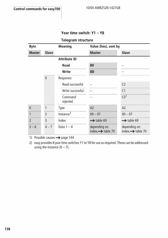
Control commands for easy700
138
10/04 AWB2528-1427GB
Year time switch: Y1 – Y8
Telegram structure
Byte Meaning Value (hex), sent by
Master Slave Master Slave
Attribute ID
Read 89 –
Write 8D –
0 Response:
Read successful – C2
Write successful – C1
Command rejected
– C01
0 1 Type A2 A2
1 2 Instance2 00 – 07 00 – 07
2 3 Index a table 69 a table 69
3 – 6 4 – 7 Data 1 – 4 depending on index,a table 70
depending on index,a table 70
1) Possible causes a page 1442) easy provides 8 year time switches Y1 to Y8 for use as required. These can be addressed
using the instance (0 – 7).
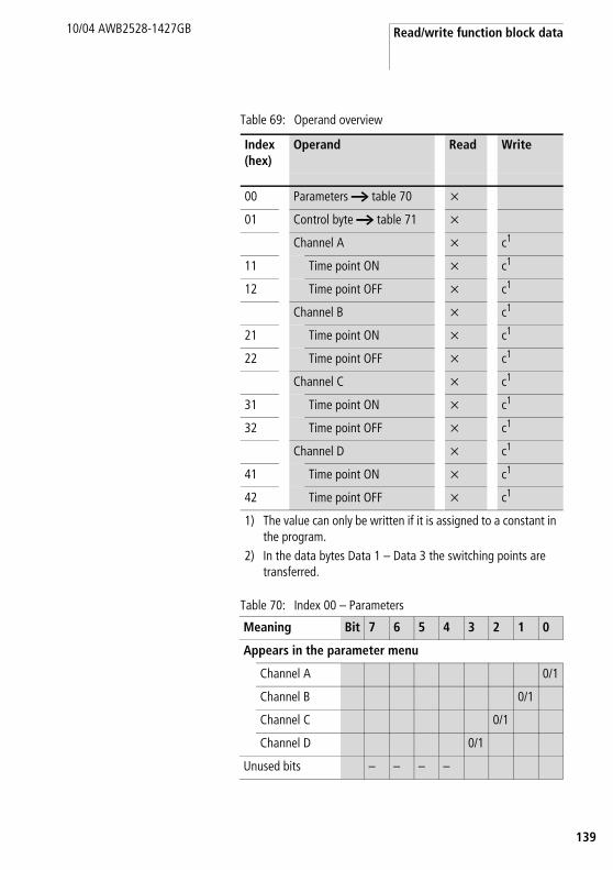
Read/write function block data
39
10/04 AWB2528-1427GB
1
Table 69: Operand overview
Table 70: Index 00 – Parameters
Index (hex)
Operand Read Write
00 Parameters a table 70 x
01 Control byte a table 71 x
Channel A x c1
11 Time point ON x c1
12 Time point OFF x c1
Channel B x c1
21 Time point ON x c1
22 Time point OFF x c1
Channel C x c1
31 Time point ON x c1
32 Time point OFF x c1
Channel D x c1
41 Time point ON x c1
42 Time point OFF x c1
1) The value can only be written if it is assigned to a constant in the program.
2) In the data bytes Data 1 – Data 3 the switching points are transferred.
Meaning Bit 7 6 5 4 3 2 1 0
Appears in the parameter menu
Channel A 0/1
Channel B 0/1
Channel C 0/1
Channel D 0/1
Unused bits – – – –

Control commands for easy700
140
10/04 AWB2528-1427GB
Example: Data 1 (Byte 4) = 0x03 l The values for the year time switch of channels A and B appear in the parameter menu.
Table 71: Index 01 – Control byte
Channel A, index 11/12Index 0x11 channel A timepoint of switch onIndex 0x12 channel A timepoint of switch off
Data 1 (Byte 4) – dayData 2 (Byte 5) – monthData 3 (Byte 6) – year
Example:The year time switch channel A should be switched on at the 21.04.2004.
Index = 0x11Data 1 = 0x15Data 2 = 0x04Data 3 = 0x04
The year time switch channel B should be switched off on the 05.11.2012.
Index = 0x22Data 1 = 0x05Data 2 = 0x0BData 3 = 0x0C
Data 1 Bit 7 6 5 4 3 2 1 0
FB output – – – – – – – Q11
1) Status 1 if count condition is fulfilled.
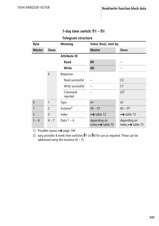
Read/write function block data
41
10/04 AWB2528-1427GB
1
7-day time switch: Ö1 – Ö8
Telegram structure
Byte Meaning Value (hex), sent by
Master Slave Master Slave
Attribute ID
Read 89 –
Write 8D –
0 Response:
Read successful – C2
Write successful – C1
Command rejected
– C01
0 1 Type A1 A1
1 2 Instance2 00 – 07 00 – 07
2 3 Index a table 72 a table 72
3 – 6 4 – 7 Data 1 – 4 depending on index,a table 73
depending on index,a table 73
1) Possible causes a page 1442) easy provides 8 week time switches Ö1 to Ö8 for use as required. These can be
addressed using the instance (0 – 7).

Control commands for easy700
142
10/04 AWB2528-1427GB
Table 72: Operand overview
Index (hex)
Operand Read Write
00 Parameters a table 73 x
01 Control byte a table 74 x
11 Channel A
Day on/off x c1
12 Time on x c1
13 Time off x c1
21 Channel B
Day on/off x c1
22 Time on x c1
23 Time off x c1
31 Channel C
Day on/off x c1
32 Time on x c1
33 Time off x c1
41 Channel D
Day on/off x c1
42 Time on x c1
43 Time off x c1
1) The value can only be written if it is assigned to a constant in the program.
2) A 16-bit value is transferred in data bytes Data 1 – Data 4. It should be remembered that Data 1 is the low byte and Data 2 the high byte.

Read/write function block data
43
10/04 AWB2528-1427GB
1
Table 73: Index 00 – Parameters
Example:Data 1 (Byte 4) = 0x03
Meaning:The values of the 7-day timer switch WH.. of channel A and B appear in the parameter menu.
Table 74: Index 01 – Control byte
Channel A, index 11/12/13Index 0x11 channel A day on/off Data 1 (Byte 4) – day onData 2 (Byte 5) – day off0x01 = Sunday ... 0x07 = Saturday
If the channel is not used the 16 bit value is equal to 0x00.
Index 0x12 – time on (2 bytes)Index 0x13 – time off (2 bytes)Data 1 (Byte 4) – hourData 2 (Byte 5) – minute
Example: time on at 13:43 Data 1 = 0x0DData 2 = 0x2B
Meaning Bit 7 6 5 4 3 2 1 0
Appears in the parameter menu
Channel A 0/1
Channel B 0/1
Channel C 0/1
Channel D 0/1
Unused bits – – – –
Data 1 Bit 7 6 5 4 3 2 1 0
FB output – – – – – – – Q11
1) Status 1 if count condition is fulfilled.

144
10/04 AWB2528-1427GB
Analysis – error codes via EASY-LINK
The easy700 basic unit will return a defined error code in the event of an incorrectly selected operating mode or an invalid telegram. The error code transferred has the following structure:
Telegram structure
Table 75: Error codes
Byte Meaning Slave transmits (value hex)
0 Answer
Command rejected C0
1 Type 00
2 Instance 00
3 Index 00
4 Error code a table 75
Error code
Description
0x01 An unknown telegram has been sent.
0x02 An unknown object has been sent.
0x03 An unknown command has been sent.
0x04 An invalid instance has been sent.
0x05 An invalid parameter set has been used.
0x06 An attempt has been made to write a variable which is not a constant.
0x0C The device is in an invalid device mode. STOP l RUN or RUN l STOP
0x0D An invalid display access occurs. Please exit the menu level to allow the status display to be shown on the display. Writing to the clock is not possible.
0xF0 An attempt has been made to control an unknown parameter.
0xF1 Invalid value
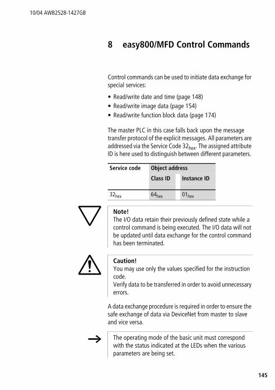
45
10/04 AWB2528-1427GB
1
8 easy800/MFD Control Commands
Control commands can be used to initiate data exchange for special services:
• Read/write date and time (page 148)• Read/write image data (page 154)• Read/write function block data (page 174)
The master PLC in this case falls back upon the message transfer protocol of the explicit messages. All parameters are addressed via the Service Code 32hex. The assigned attribute ID is here used to distinguish between different parameters.
A data exchange procedure is required in order to ensure the safe exchange of data via DeviceNet from master to slave and vice versa.
Service code Object address
Class ID Instance ID
32hex 64hex 01hex
h Note!The I/O data retain their previously defined state while a control command is being executed. The I/O data will not be updated until data exchange for the control command has been terminated.
i Caution!You may use only the values specified for the instruction code.Verify data to be transferred in order to avoid unnecessary errors.
h The operating mode of the basic unit must correspond with the status indicated at the LEDs when the various parameters are being set.

easy800/MFD Control Commands
146
10/04 AWB2528-1427GB
The master transmits a control command to initiate data exchange between the communication partners. The slave always returns an answer to this request, which indicates whether data has been exchanged or not. An error code will be returned if data exchange has failed. This code is precisely defined in the ODVA specifications.
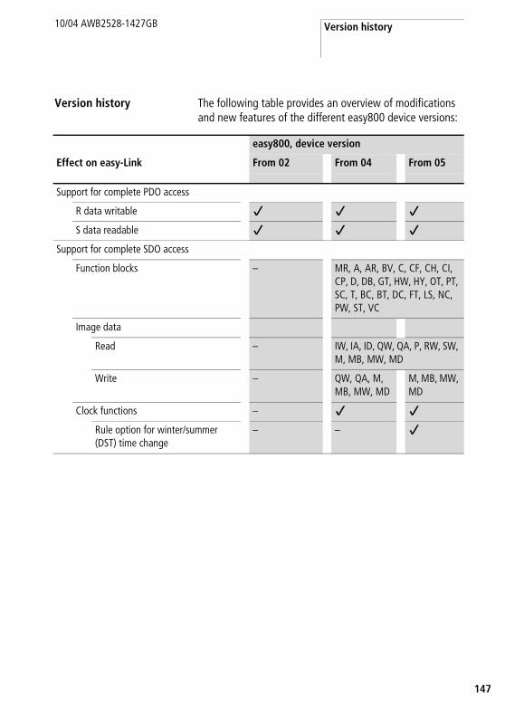
Version history
47
10/04 AWB2528-1427GB
1
Version history The following table provides an overview of modifications and new features of the different easy800 device versions:
easy800, device version
Effect on easy-Link From 02 From 04 From 05
Support for complete PDO access
R data writable j j j
S data readable j j j
Support for complete SDO access
Function blocks – MR, A, AR, BV, C, CF, CH, CI, CP, D, DB, GT, HW, HY, OT, PT, SC, T, BC, BT, DC, FT, LS, NC, PW, ST, VC
Image data
Read – IW, IA, ID, QW, QA, P, RW, SW, M, MB, MW, MD
Write – QW, QA, M, MB, MW, MD
M, MB, MW, MD
Clock functions – j j
Rule option for winter/summer (DST) time change
– – j
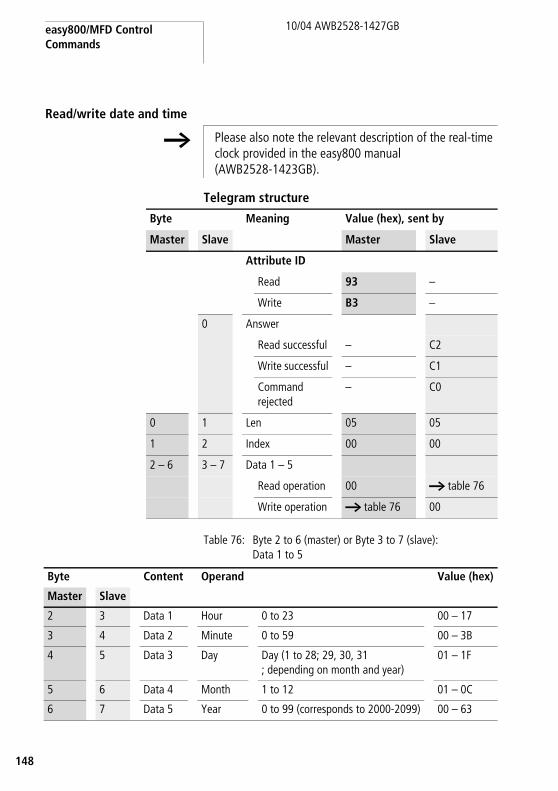
easy800/MFD Control Commands
148
10/04 AWB2528-1427GB
Read/write date and time
Telegram structure
Table 76: Byte 2 to 6 (master) or Byte 3 to 7 (slave): Data 1 to 5
h Please also note the relevant description of the real-time clock provided in the easy800 manual (AWB2528-1423GB).
Byte Meaning Value (hex), sent by
Master Slave Master Slave
Attribute ID
Read 93 –
Write B3 –
0 Answer
Read successful – C2
Write successful – C1
Command rejected
– C0
0 1 Len 05 05
1 2 Index 00 00
2 – 6 3 – 7 Data 1 – 5
Read operation 00 a table 76
Write operation a table 76 00
Byte Content Operand Value (hex)
Master Slave
2 3 Data 1 Hour 0 to 23 00 – 17
3 4 Data 2 Minute 0 to 59 00 – 3B
4 5 Data 3 Day Day (1 to 28; 29, 30, 31; depending on month and year)
01 – 1F
5 6 Data 4 Month 1 to 12 01 – 0C
6 7 Data 5 Year 0 to 99 (corresponds to 2000-2099) 00 – 63

Read/write date and time
49
10/04 AWB2528-1427GB
1
Winter/summer time, DST
Telegram structureByte Meaning Value (hex), sent by
Master Slave Master Slave
Attribute ID
Read 93 –
Write B3 –
0 Answer
Read successful – C2
Write successful – C1
Command rejected – C0
0 1 Len 05 05
1 2 Index
01: Summer/Winter time a table 77 a table 77
02: Winter time (to the “Area” = rule”)1
a table 78 a table 78
2 – 6 3 – 7 Data 1 – 5
Read operation 00 depending on index, a table 77,78
Write operation depending on index, a table 77,78
00
1) Detailed setting possibilities for easy800/MFD from version 05

easy800/MFD Control Commands
150
10/04 AWB2528-1427GB
Table 77: Index 01 – Summer/Winter time switchover
Byte Content Value (hex)
Master Slave
2 3 Data 1 Area
None 00
Manual 01
Automatic EU 02
Automatic GB 03
Automatic US 04
Rule1 05
for “Area” = “manual”:
3 4 Data 2 Set summer time day (1 to 28, 29, 30, 31 depending on month and year)
00 – 3B
4 5 Data 3 Set Summer time month (1 to 12)
01 – 1F
5 6 Data 4 Set winter time day (1 to 28, 29, 30, 31 depending on month and year)
01 – 0C
6 7 Data 5 Set Winter time month (1 to 12) 00 – 63
for “Area” = “Rule”1:
3 – 6 4 – 7 Data 2 – 5 Summer time switching rule a table 79
1) Detailed setting possibilities for easy800/MFD from version 05
Read/write date and time
51
10/04 AWB2528-1427GB
1
Table 78: Index 02 – Winter time (only valid if Area = “Rule” selected)
Switching rule bit array
Byte Content Value (hex)
Master Slave
2 3 Data 1 Area = Rule 01
3 – 6 4 – 7 Data 2 – 5 Winter time switching rule a table 79
h Please also read the detailed description in the easy800 manual (AWB2528-1423GB). The following table shows the composition of the corresponding data bytes.

easy800/MFD Control Commands
152
10/04 AWB2528-1427GB
Tabl
e 79
:Sw
itchi
ng ru
le b
it ar
ray
Dat
a 5
Dat
a 4
Dat
a 3
Dat
a 2
Bit
3130
2928
2726
2524
2322
2120
1918
1716
1514
1312
1110
98
76
54
32
10
Rule
_1D
ayRu
le_2
Day
Mon
thTi
me
of t
ime
chan
geD
iffer
enc
e
0:on
0:Su
0:m
onth
0 to
30
0 to
11
Hour
: 0 to
23
Min
ute:
0 to
59
0:0:
30h
1:on
the
first
1:M
o1:
afte
r1:
1:00
h
2:on
the
seco
nd2:
Tu2:
befo
re2:
1:30
h
3:on
the
third
3:W
e3:
2:00
h
4:on
the
four
th4:
Thu
4:2:
30h
5:on
the
last
5:Fr
5:3:
00h
6:Sa

Read/write date and time
53
10/04 AWB2528-1427GB
1
ExampleThe real-time clock of the easy800 is to be set to Friday 23.05.2003, 14:36.
Byte Meaning Value (hex), sent by
Master Slave Master Slave
Attribute ID: Write B3 –
0 Response: Writesuccessful
– C1
0 1 Len 05 05
1 2 Index 00 00
2 3 Data 1 (hex) 0E 00
3 4 Data 2 (minute) 24 00
4 5 Data 3 (day) 17 00
5 6 Data 4 (month) 05 00
6 7 Data 5 (year) 03 00
h All values must be transferred as hexadecimal values.

easy800/MFD Control Commands
154
10/04 AWB2528-1427GB
Read/write image data
Overview
h Please also observe the relevant description of possible image data provided in the easy800 manual (AWB2528-1423GB) or in the EASY-SOFT Help. The information provided in section “General notes on working with image data” on page 61 also applies to easy700.
Operands Meaning Read/Write Command (hex)
Page
IA1 – IA4 “Local analog inputs: IA1 – IA4“ read 02 155
ID1 – ID16 “Local diagnostics: ID1 – ID16“ read 03 157
IW0 “Read local inputs: IW0“ read 01 159
IW1 – IW8 “Inputs of the network station: IW1 – IW8“
read 01 161
M... “Marker: M..“ read/write 0B – 0E 162
P1 – P4 “Local P buttons: P1 – P4“ read 06 165
QA1 “Local analog output: QA1“ read/write 05 167
QW0, QW1 – QW8
“Local outputs: QW0/ outputs of the network station: QW1 – QW8“
read/write 04 168
R1 – R16S1 – S8
“Inputs/outputs of EASY-LINK: RW/SW“ read 07/09 170
RN1 – RN32SN1 – SN32
“Receive data network: RN1 – RN32/ Send data network: SN1 – SN32“
read 08/0A 172
Read/write image data
55
10/04 AWB2528-1427GB
1
Local analog inputs: IA1 – IA4
The analog inputs on the easy800 and MFD basic units can be read directly via DeviceNet. The 16-bit value is transferred in Intel format (Low Byte first).
Telegram structure
Byte Meaning Value (hex), sent by
Master Slave Master Slave
Attribute ID: Read
91 –
0 Response:
Read successful – C2
Command rejected
– C0
0 1 Len 02 02
1 2 Type 02 02
2 3 Index 01 – 041 01 – 041
3 4 Data 1 (Low Byte) 00 a example on page 1564 5 Data 2 (High Byte) 00
5 – 6 6 – 7 Data 3 – 4 00 00
1) 01 = Analog input I702 = Analog input I803 = Analog input I1104 = Analog input I12

easy800/MFD Control Commands
156
10/04 AWB2528-1427GB
ExampleA voltage signal is present at analog input 1. The required telegrams for reading the analog value are as follows:
Byte 4 – Data 1 (Low Byte): D9hex
Byte 5 – Data 2 (High Byte): 02hex
l corresponding 16-bit value: 02D9hex = 729 (7.29 V)
Byte Meaning Value (hex), sent by
Master Slave Master Slave
Attribute ID: Read 91 –
0 Response: Readsuccessful
– C2
0 1 Len 02 02
1 2 Type 02 02
2 3 Index 011 011
3 4 Data 1 00 D9
4 5 Data 2 00 02
5 6 Data 3 00 00
6 7 Data 4 00 00
1) 01 = Analog input 1

Read/write image data
57
10/04 AWB2528-1427GB
1
Local diagnostics: ID1 – ID16
The local diagnostics (ID1 – ID8) bytes indicate the status of the individual NET stations. The connection to the remote station (only MFD) is indicated via ID9.
Telegram structure
Byte Meaning Value (hex), sent by
Master Slave Master Slave
Attribute ID: Read 91 –
0 Response:
Read successful – C2
Command rejected – C0
0 1 Len 02 02
1 2 Type 03 03
2 3 Index 00 00
3 4 Data 1 (Low Byte) 00 a table 80
4 5 Data 2 (High Byte) 00 a table 80
5 – 6 6 – 7 Data 3 – 4 00 00

easy800/MFD Control Commands
158
10/04 AWB2528-1427GB
Table 80: Byte 4 to 5: Data 1 to 2
ExampleData 1 = F8, Data 2 = FF l In the easy-NET network, the three stations are present with the NET IDs 1, 2, 3
Data 1 Bit 7 6 5 4 3 2 1 0
ID1 0/1
ID2 0/1
.. ..
ID8 0/1
Data 2 Bit 7 6 5 4 3 2 1 0
ID9 0/1
– 1
... ...
– 1
0/1= active/inactive NET station, –= not assigned

Read/write image data
59
10/04 AWB2528-1427GB
1
Read local inputs: IW0
This command string enables you to read the local inputs of the easy800/MFD. The relevant input word is stored in Intel format.
Telegram structure
Table 81: Byte 4 to 5: Data 1 to 2
Byte Meaning Value (hex), sent by
Master Slave Master Slave
Attribute ID: Read 91 –
0 Response:
Read successful – C2
Command rejected – C0
0 1 Len 02 02
1 2 Type 01 01
2 3 Index 00 00
3 4 Data 1 (Low Byte) 00 a table 81
4 5 Data 2 (High Byte) 00 a table 81
5 – 6 6 – 7 Data 3 – 4 00 00
Data 1 Bit 7 6 5 4 3 2 1 0
I1 0/1
I2 0/1
.. ..
I8 0/1
Data 2 Bit 7 6 5 4 3 2 1 0
I9 0/1
I10 0/1
.. ..
I16 0/1
easy800/MFD Control Commands
160
10/04 AWB2528-1427GB
Example: Read local inputs IW0
The values Data 1 = C4 and Data 2 = 02 indicate that the inputs I8, I7, I3 and I10 have been set to 1.
Byte Meaning Value (hex), sent by
Master Slave Master Slave
Attribute ID: Read
91 –
0 Response: Readsuccessful
– C2
0 1 Len 02 02
1 2 Type 01 01
2 3 Index 00 00
3 4 Data 1 00 C4
4 5 Data 2 00 02
5 6 Data 3 00 00
6 7 Data 4 00 00
h All values must be transferred as hexadecimal values.
Read/write image data
61
10/04 AWB2528-1427GB
1
Inputs of the network station: IW1 – IW8
The easy800 and MFD devices can be remotely expanded very simply using the EASYNET. The service offered here makes it possible to implement read access to the inputs of individual NET stations.
Telegram structure
Byte Meaning Value (hex), sent by
Master Slave Master Slave
Attribute ID: Read 91 –
0 Response:
Read successful – C2
Command rejected – C0
0 1 Len 02 02
1 2 Type 01 01
2 3 Index 01 – 081 01 – 081
3 4 Data 1 (Low Byte) 00 a table 81on page 159.4 5 Data 2 (High Byte) 00
5 – 6 6 – 7 Data 3 – 4 00 00
1) Corresponds to address of network station

easy800/MFD Control Commands
162
10/04 AWB2528-1427GB
Marker: M..
Byte Meaning Value (hex), sent by
Master Slave Master Slave
Attribute ID
Read 91 –
Write B1 –
0 Answer
Read successful – C2
Write successful – C1
Command rejected
– C0
0 1 Len a table 82 a table 82
1 2 Type
2 3 Index
3 – 6 4 – 7 Data 1 – 4
Read operation 00 a “Example 1: Set/reset market bit“ on page 164
Write operation a “Example 2: Write marker word“ on page 164
00

Read/write image data
63
10/04 AWB2528-1427GB
1
Table 82: Byte 0 to 2 (master) or: Byte 1 to 3 slave: Len, Type, Index
If required, refer to the more detailed description of the marker allocation in the easy800 manual. Only a small extract of this manual is shown at this point in order to illustrate the allocation principle.
Operand Len Type Index
Marker bit M1 .. M96 01hex 0Bhex 01 to 60hex
Marker byte MB1 .. MB96 01hex 0Chex 01 to 60hex
Marker word MW1 .. MW96 02hex 0Dhex 01 to 60hex
Marker double word MD1 .. MD96 04hex 0Ehex 01 to 60hex
Note!The function blocks and DW markers (32-bit values) of easy800/MFD operate with signed values.
Applies to MD, MW, MB, M
Left = Most significant bit, byte, word
Right = Least significant bit, byte, word
32 bit MD1
16 bit MW2 MW1
8 bit MB4 MB3 MB2 MB1
1 bit M32 to M25 M24 to M17 M16 to M9 M8 to M1
32 bit MD2
16 bit MW4 MW3
8 bit MB8 MB7 MB6 MB5
1 bit M64 to M57 M56 to M49 M48 to M41 M40 to M33
h The relevant marker values are transferred in Intel format. In other words, the first byte is the low byte (Byte 4) and the last byte the high byte.

easy800/MFD Control Commands
164
10/04 AWB2528-1427GB
Example 1: Set/reset market bitMarker bit 62 should be set or reset. Write a “1” to set or a “0” to reset the marker bit in the least significant bit of data byte “Data 1”.
Example 2: Write marker wordThe value 823 should be written into the marker word MW32: 823dec = 337hex r Data 1 = 37hex, Data 2 = 03hex
Byte Meaning Value (hex), sent by
Master Slave Master Slave
Attribute ID: Write B1 –
0 Response: Write successful – C1
0 1 Len 01 01
1 2 Type 0B 0B
2 3 Index 3E 3E
3 4 Data 1 0101) 00
4 – 6 5 – 7 Data 2 – 4 00 00
1) 01 = set, 00 = reset
Byte Meaning Value (hex), sent by
Master Slave Master Slave
Attribute ID: Write B1 –
0 Response: Write successful – C1
0 1 Len 01 01
1 2 Type 0D 0D
2 3 Index 20 20
3 4 Data 1 37 00
4 5 Data 2 03 00
5 6 Data 3 00 00
6 7 Data 4 00 00

Read/write image data
65
10/04 AWB2528-1427GB
1
Local P buttons: P1 – P4
The local P buttons are the display cursor buttons of the easy800/MFD basic unit. You can scan the buttons in both RUN and STOP mode.
Only one byte has to be transferred for the P buttons.
h Ensure that the P buttons are also activated via the SYSTEM menu (in the basic unit).
Byte Meaning Value (hex), sent by
Master Slave Master Slave
Attribute ID: Read 91 –
0 Response:
Read successful – C2
Command rejected – C0
0 1 Len 02 02
1 2 Type 06 06
2 3 Index 00 00
3 4 Data 1 (Low Byte) 00 a table 83
4 – 6 5 – 7 Data 2 – 4 00 00

easy800/MFD Control Commands
166
10/04 AWB2528-1427GB
Table 83: Byte 4: Data
Data 1 Bit 7 6 5 4 3 2 1 0
P1 0/1
P2 0/1
P3 0/1
P4 0/1
– 0
– 0
– 0
– 0

Read/write image data
67
10/04 AWB2528-1427GB
1
Local analog output: QA1
The commands provided can be used to access the local analog output of the easy800 or MFD basic unit. When writing to the analog output (only possible from easy800, device version 04) the value will only be output if the respective device is in RUN mode and if the respective image is not written by the actual program, a section “Read/write image data”on page 154.
Example:The analog output should output a value of approx. 5 V.
500 = 01F4hex Byte 4 – Data 1 (LowByte) : F4hexByte 5 – Data 2 (HighByte): 01hex
Byte Meaning Value (hex), sent by
Master Slave Master Slave
Attribute ID
Read 91 –
Write1) B1 –
0 Answer
Read successful – C2
Write successful – C1
Command rejected – C0
0 1 Len 02 02
1 2 Type 05 05
2 3 Index 00 00
3 – 4 4 – 5 Data 1 – 2
Read operation 00 a example
Write operation a example
00
5 – 6 6 – 7 Data 3 – 4 00 00
1) Writing is only possible from easy800, version 0.4 a section “Read/write date and time” on page 148.

easy800/MFD Control Commands
168
10/04 AWB2528-1427GB
Local outputs: QW0/outputs of the network station: QW1 – QW8
The local outputs can be read directly via DeviceNet, and from easy800 version 04 they can also be written. However, the outputs are only switched externally if the device is in Run mode and the addressed output is not being used in the circuit diagram. a section “Read/write image data” on page 154.
Telegram structure
Byte Meaning Value (hex), sent by
Master Slave Master Slave
Attribute ID
Read 91 –
Write1) B1 –
0 Answer
Read successful – C2
Write successful – C1
Command rejected
– C0
0 1 Len 02 02
1 2 Type 04 04
2 3 Index2) 00/01 – 08 00/01 – 08
3 4 Data 1
Read operation 00 a table 80
Write operation a table 84 00
4 – 6 5 – 7 Data 2 – 4 00 00
1) Writing is only possible from easy800, device version 04 a section “Read/write date and time” on page 148.
2) 00 = Local output01 – 08 = Outputs of network stations 1 – 8

Read/write image data
69
10/04 AWB2528-1427GB
1
Table 84: Byte 4: Data
Data 1 Bit 7 6 5 4 3 2 1 0
Q1 0/1
Q2 0/1
Q3 0/1
Q4 0/1
Q5 0
Q6 0
Q7 0
Q8 0

easy800/MFD Control Commands
170
10/04 AWB2528-1427GB
Inputs/outputs of EASY-LINK: RW/SW
This service allows you to read the local R and S data and the data of the NET stations (1 – 8) transferred via EASYLINK, again from the relevant easy800/MFD image.
Byte Meaning Value (hex), sent by
Master Slave Master Slave
Attribute ID: Read 91 –
Response:
0 Read successful – C2
Command rejected – C0
0 1 Len 02 02
1 2 Type For RW: 07 For RW: 07
2 For SW: 09 For SW: 09
3 Index 00/01 – 081 00/01 – 081
3 4 Data 1 (Low Byte) 00 a table 85
4 5 Data 2 (High Byte) 00 a table 85
5 – 6 6 – 7 Data 3 – 4 00 00
1) 00 = Local input/output01 – 08 = Address of network station (NET-ID 1 – 8)

Read/write image data
71
10/04 AWB2528-1427GB
1
Table 85: Byte 4 to 5: Data 1 to 2
Data 1 Bit 7 6 5 4 3 2 1 0
RW SW
R1 S1 0/1
R2 S2 0/1
R3 S3 0/1
R4 S4 0/1
R5 S5 0/1
R6 S6 0/1
R7 S7 0/1
R8 S8 0/1
Data 2 Bit 7 6 5 4 3 2 1 0
R9 – 0/1
R10 – 0/1
R11 – 0/1
R12 – 0/1
R13 – 0/1
R14 – 0/1
R15 – 0/1
R16 – 0/1

easy800/MFD Control Commands
172
10/04 AWB2528-1427GB
Receive data network: RN1 – RN32/Send data network: SN1 – SN32
EASYNET allows a point-to-point connection to be implemented between the individual NET stations. The RN and SN data are used for the data exchange (see the easy800 manual).
h The RN SN data of the local device (Index = 0) to which the EASY204-DP is fitted cannot be scanned. In this case the command would be denied with the 0Chex signal.
Byte Meaning Value (hex), sent by
Master Slave Master Slave
Attribute ID: Read 91 –
0 Response:
Read successful – C2
Command rejected – C0
0 1 Len 04 04
1 2 Type For RN1 – RN32: 08 For RN1 – RN32: 08
For SN1 – SN32: 0A For SN1 – SN32: 0A
2 3 Index 01 – 081 01 – 081
3 – 6 4 – 7 Data 1 – 4 00 a table 86
1) Corresponds to NET-ID

Read/write image data
73
10/04 AWB2528-1427GB
1
Table 86: Byte 4 to 7: Data 1 to 4
Data 1 Bit 7 6 5 4 3 2 1 0
RN1 SN1 ... 0/1
... 0/1
RN8 SN8 0/1
Data 2 Bit 7 6 5 4 3 2 1 0
RN9 SN9 0/1
.... ...
RN16 SN16 0/1
Data 3 Bit 7 6 5 4 3 2 1 0
RN17 SN17 0/1
... ...
RN24 SN24 0/1
Data 4 Bit 7 6 5 4 3 2 1 0
RN25 SN25 0/1
... ...
RN32 SN32 0/1

easy800/MFD Control Commands
174
10/04 AWB2528-1427GB
Read/write function block data
General notes
Always note the following when working with function blocks:
• The relevant data is transferred in Intel format. In other words, the first byte is the low byte (Byte 4) and the last byte (byte 7) the high byte.
• The maximum data length is 4 bytes. All values must be transferred in hexadecimal format.
• All 32-bit values are treated as signed values. When transferring 32-bit values, ensure that the appropriate value range is suitable for long integers, i.e. signed.32-bit value: –2147483648 .. 0 .. +2147483647
h Please also note the relevant description of the function blocks provided in the easy800 manual.

Read/write function block data
75
10/04 AWB2528-1427GB
1
Overview
Operands Meaning Read/Write Type(hex)
Page
A01 – A32 “Analog value comparator: A01 – A32“ Read/Write 11 176
AR01 – AR32 “Arithmetic function block: AR01 – AR32“ Read/Write 12 178
BC01 – BC32 “Block Compare: BC01 – BC32“ Read/Write 25 180
BT01 – BT32 “Block Transfer: BT01 – BT32“ Read/Write 26 182
BV01 – BV32 “Boolean operation: BV01 – BV32“ Read/Write 13 184
C01 – C32 “Counter: C01 – C32“ Read/Write 14 186
CF01 – CF04 “Frequency counters: CF01 – CF04“ Read/Write 15 188
CH01 – CH04 “High-speed counter: CH01 – CH04“ Read/Write 16 190
CI01 – CI02 “Incremental encoder counters: CI01 – CI02“ Read/Write 17 192
CP01 – CP32 “Comparator: CP01 – CP32“ Read/Write 18 194
D01 – D32 “Text output function block: D01 – D32“ Read/Write 19 196
DB01 – DB32 “Data block: DB01 – DB32“ Read/Write 1A 199
DC01 – DC32 “PID controller: DC01 – DC32“ Read/Write 27 201
FT01 – FT32 “Signal smoothing filter: FT01 – FT32“ Read/Write 28 204
GT01 – GT32 “Receipt of network data: GT01 – GT32“ Read 1B 206
HW01 – HW32 “7-day time switch: HW01 – HW32“ Read 1C 208
HY01 – HY32 “Year time switch: HY01 – HY32“ Read 1D 211
LS01 – LS32 “Value scaling: LS01 – LS32“ Read/Write 29 214
MR01 – MR32 “Master reset: MR01 – MR32“ Read 0F 216
NC01 – NC32 “Numerical converter: NC01 – NC32“ Read/Write A 2 218
OT01 – OT04 “Hours-run meters: OT01 – OT04“ Read/Write 1E 220
PT01 – PT32 “Sending of network data: PT01 – PT32“ Read 1F 222
PW01 – PW02 “Pulse width modulation: PW01 – PW02“ Read/Write 2B 224
SC01 “Synchronize clock function block: SC01“ Read 20 226
ST01 “Set cycle time function block: ST01“ Read/Write 2C 227
T01 – T32 “Timing relays: T01 – T32“ Read/Write 21 229
VC01 – VC32 “Value limitation: VC01 – VC32“ Read/Write 2D 232

easy800/MFD Control Commands
176
10/04 AWB2528-1427GB
Analog value comparator: A01 – A32
Telegram structure
Byte Meaning Value (hex), sent by
Master Slave Master Slave
Attribute ID
Read 92 –
Write B2 –
0 Response:
Read successful – C2
Write successful – C1
Command rejected
– C0
0 1 Type 11 11
1 2 Instance 01 – 20 01 – 20
2 3 Index a table 87 a table 87
3 – 6 4 – 7 Data 1 – 4 00 depending on index, a table 88, 89

Read/write function block data
77
10/04 AWB2528-1427GB
1
Table 87: Operand overview
Table 88: Index 0 – Bit IO
Table 89: Index 1 - Mode
Index (hex)
Operand read write
00 Bit IO, a table 88 x
01 Mode, a table 89 x
02 Comparison value 1 I1 x c1
03 Gain factor for I1 (I1 = F1 x value) F1 x c1
04 Comparison value 2 I2 x c1
05 Gain factor for I2 (I2 = F2 x value) F2 x c1
06 Offset for value I1 OS x c1
07 Switching hysteresis for value I2 (the value of HY is for both positive and negative hysteresis.)
HY x c1
1) The value can only be written if it is assigned to a constant in the program.
h The data for index 2 to 7 is transferred as a 32-bit value in Intel format (Data 1 – Low Byte to Data 4 – High Byte).
Bit 7 6 5 4 3 2 1 0
FB output Data 3 – – – – – – CY1 Q12
1) Status 1 if the value range is exceeded2) Status 1 if the condition is fulfilled
(e.g. I1 < I2 with LT mode)
Data 1 (hex)
00 LT Less than (I1 < I2)
01 EQ Equal to (I1 = I2)
02 GT Greater than (I1 > I2)

easy800/MFD Control Commands
178
10/04 AWB2528-1427GB
Arithmetic function block: AR01 – AR32
Telegram structure
Byte Meaning Value (hex), sent by
Master Slave Master Slave
Attribute ID
Read 92 –
Write B2 –
0 Response:
Read successful – C2
Write successful – C1
Command rejected
– C0
0 1 Type 12 12
1 2 Instance 01 – 20 01 – 20
2 3 Index a table 90 a table 90
3 – 6 4 – 7 Data 1 – 4
Read operation 00 depending on index, a table 91, 92
Write operation depending on index, a table 91, 92
00

Read/write function block data
79
10/04 AWB2528-1427GB
1
Table 90: Operand overview
Table 91: Index 0 – Bit IO
Table 92: Index 1 - Mode
Index (hex)
Operand read write
00 Bit IO, a table 91 x
01 Mode, a table 92 x
02 First operand I1 x c1
03 Second operand I2 x c1
04 Result QV x
1) The value can only be written if it is assigned to a constant in the program.
h The data for index 2 to 4 is transferred as a 32-bit value in Intel format (Data 1 – Low Byte to Data 4 – High Byte).
Bit 7 6 5 4 3 2 1
FB output Data 3 – – – – – ZE1 CY1
1) Status 1 if the value of the function block output QV (the calculation result) equals zero
2) Status 1 if the value range is exceeded
Data 1 (hex)
00 ADD Add (I1 + I2 = QV)
01 SUB Subtract (I1 – I2 = QV)
02 MUL Multiply (I1 x I2 = QV)
03 DIV Divide (I1 : I2 = QV)

easy800/MFD Control Commands
180
10/04 AWB2528-1427GB
Block Compare: BC01 – BC32
Telegram structure
Byte Meaning Value (hex), sent by
Master Slave Master Slave
Attribute ID
Read 92 –
Write B2 –
0 Response:
Read successful – C2
Write successful – C1
Command rejected
– C0
0 1 Type 25 25
1 2 Instance 01 – 20 01 – 20
2 3 Index a table 93 a table 93
3 – 6 4 – 7 Data 1 – 4
Read operation 00 depending on index, a table 94, 95
Write operation depending on index, a table 94, 95
00
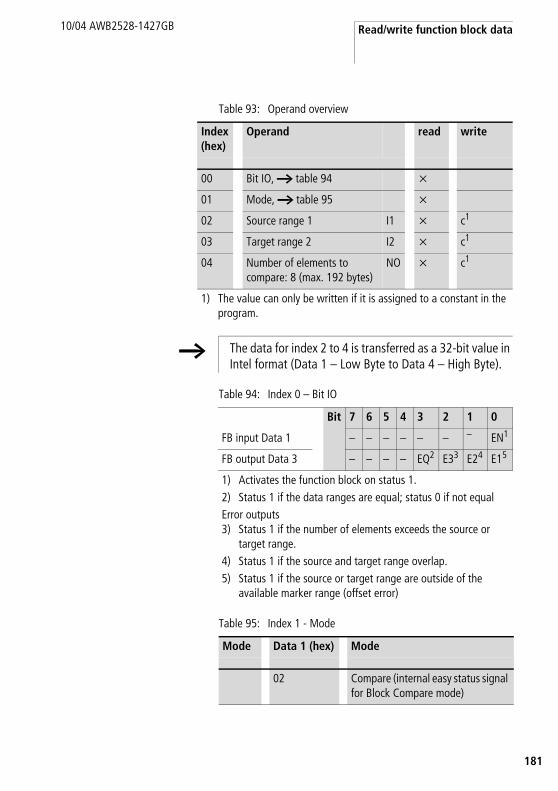
Read/write function block data
81
10/04 AWB2528-1427GB
1
Table 93: Operand overview
Table 94: Index 0 – Bit IO
Table 95: Index 1 - Mode
Index (hex)
Operand read write
00 Bit IO, a table 94 x
01 Mode, a table 95 x
02 Source range 1 I1 x c1
03 Target range 2 I2 x c1
04 Number of elements to compare: 8 (max. 192 bytes)
NO x c1
1) The value can only be written if it is assigned to a constant in the program.
h The data for index 2 to 4 is transferred as a 32-bit value in Intel format (Data 1 – Low Byte to Data 4 – High Byte).
Bit 7 6 5 4 3 2 1 0
FB input Data 1 – – – – – – – EN1
FB output Data 3 – – – – EQ2 E33 E24 E15
1) Activates the function block on status 1.2) Status 1 if the data ranges are equal; status 0 if not equal Error outputs3) Status 1 if the number of elements exceeds the source or
target range.4) Status 1 if the source and target range overlap. 5) Status 1 if the source or target range are outside of the
available marker range (offset error)
Mode Data 1 (hex) Mode
02 Compare (internal easy status signal for Block Compare mode)
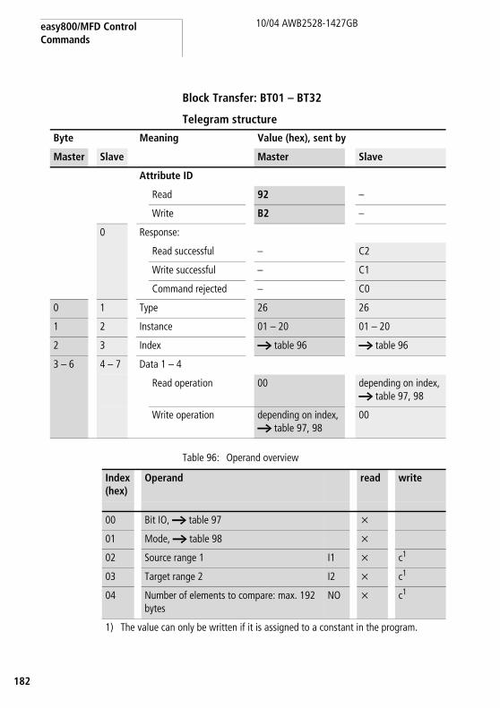
easy800/MFD Control Commands
182
10/04 AWB2528-1427GB
Block Transfer: BT01 – BT32
Telegram structure
Table 96: Operand overview
Byte Meaning Value (hex), sent by
Master Slave Master Slave
Attribute ID
Read 92 –
Write B2 –
0 Response:
Read successful – C2
Write successful – C1
Command rejected – C0
0 1 Type 26 26
1 2 Instance 01 – 20 01 – 20
2 3 Index a table 96 a table 96
3 – 6 4 – 7 Data 1 – 4
Read operation 00 depending on index, a table 97, 98
Write operation depending on index, a table 97, 98
00
Index (hex)
Operand read write
00 Bit IO, a table 97 x
01 Mode, a table 98 x
02 Source range 1 I1 x c1
03 Target range 2 I2 x c1
04 Number of elements to compare: max. 192 bytes
NO x c1
1) The value can only be written if it is assigned to a constant in the program.

Read/write function block data
83
10/04 AWB2528-1427GB
1
Table 97: Index 0 – Bit IO
Table 98: Index 1 - Mode
h The data for index 2 and 3 is transferred as a 32-bit value in Intel format (Data 1 – Low Byte .. Data 2 - High Byte).
Bit 7 6 5 4 3 2 1 0
FB input Data 1 – – – – – – – T1
FB output Data 3 – – – – – E32 E23 E14
1) Transfer of the source address specified at I1 to the target address specified at I2 on rising edge.
Error outputs2) Status 1 if the number of elements exceeds the source or
target range.3) Status 1 if the source and target range overlap. 4) Status 1 if the source or target range are outside of the
available marker range (offset error)
Data 1 (hex)
Mode
00 INI: Initialises the target range with a byte value stored at the source address.
01 CPY: Copies a data block from a source to a target range. Data block size is specified at NO.

easy800/MFD Control Commands
184
10/04 AWB2528-1427GB
Boolean operation: BV01 – BV32
Telegram structure
Byte Meaning Value (hex), sent by
Master Slave Master Slave
Attribute ID
Read 92 –
Write B2 –
0 Response:
Read successful – C2
Write successful – C1
Command rejected
– C0
0 1 Type 13 13
1 2 Instance 01 – 20 01 – 20
2 3 Index a table 99 a table 99
3 – 6 4 – 7 Data 1 – 4
Read operation 00 depending on index, a table 100, 101
Write operation depending on index, a table 100, 101
00

Read/write function block data
85
10/04 AWB2528-1427GB
1
Table 99: Operand overview
Table 100: Index 0 – Bit IO
Table 101: Index 1 - Mode
Index (hex)
Operand read write
00 Bit IO, a table 100 x
01 Mode, a table 101 x
02 First operand I1 x c1
03 Second operand I2 x c1
04 Operation result QV x
1) The value can only be written if it is assigned to a constant in the program.
h The data for index 2 to 4 is transferred as a 32-bit value in Intel format (Data 1 – Low Byte to Data 4 – High Byte).
Bit 7 6 5 4 3 2 1
FB output Data 3 – – – – – – ZE1
1) Status 1 if the value of the function block output QV (the operation result) equals zero
Data 1 (hex)
00 AND And sequence
01 OR Or sequence
02 XOR Exclusive Or sequence
03 NET Inverts the individual bits of the value at I1. The inverted value is represented as a signed decimal value.

easy800/MFD Control Commands
186
10/04 AWB2528-1427GB
Counter: C01 – C32
Telegram structure
Byte Meaning Value (hex), sent by
Master Slave Master Slave
Attribute ID
Read 92 –
Write B2 –
0 Response:
Read successful – C2
Write successful – C1
Command rejected
– C0
0 1 Type 14 14
1 2 Instance 01 – 20 01 – 20
2 3 Index a table 102 a table 102
3 – 6 4 – 7 Data 1 – 4
Read operation 00 depending on index,a table 103
Write operation depending on index,a table 103
00

Read/write function block data
87
10/04 AWB2528-1427GB
1
Table 102: Operand overview
Table 103: Index 0 – Bit IO
Index (hex)
Operand Value read write
00 Bit IO a table 103 x
01 Mode/Parameter – – –
02 Upper setpoint SH In integer range from –2147483648 to +2147483647
x c1
03 Lower setpoint SL x c1
04 Preset actual value SV x c1
05 Actual value in Run mode QV x
1) The value can only be written if it is assigned to a constant in the program.
h The data for index 2 to 5 is transferred as a 32-bit value in Intel format (Data 1 – Low Byte to Data 4 – High Byte).
Bit 7 6 5 4 3 2 1 0
FB input Data 1 – – – – SE1 D2 C3 RE4
FB output Data 3 – – – – ZE5 CY6 FB7 OF8
1) Transfer preset actual value on rising edge2) Count direction: 0 = up counting, 1 = down counting3) Count coil, counts on every rising edge4) Reset actual value to zero5) Zero: Status 1 if the value of the function block output QV (the
counter status) equals zero6) Carry: Status 1 if the value range is exceeded7) Fall below: Status 1 if the actual value F lower setpoint8) Overflow: Status 1 if the actual value f upper setpoint

easy800/MFD Control Commands
188
10/04 AWB2528-1427GB
Frequency counters: CF01 – CF04
Telegram structure
Byte Meaning Value (hex), sent by
Master Slave Master Slave
Attribute ID
Read 92 –
Write B2 –
0 Response:
Read successful – C2
Write successful – C1
Command rejected
– C0
0 1 Type 15 15
1 2 Instance 01 – 04 01 – 04
2 3 Index a table 104 a table 104
3 – 6 4 – 7 Data 1 – 4
Read operation 00 depending on index,a table 105
Write operation depending on index,a table 105
00

Read/write function block data
89
10/04 AWB2528-1427GB
1
Table 104: Operand overview
Table 105: Index 0 – Bit IO
Index (hex)
Operand read write
00 Bit IO, a table 105 x
01 Mode/Parameter – –
02 Upper setpoint SH x c1
03 Lower setpoint SL x c1
04 Actual value in Run mode
QV x
1) The value can only be written if it is assigned to a constant in the program.
h The data for index 2 to 4 is transferred as a 32-bit value in Intel format (Data 1 – Low Byte to Data 4 – High Byte).
Bit 7 6 5 4 3 2 1 0
FB input Data 1 – – – – – – – EN1
FB output Data 3 – – – – – ZE2 FB3 OF4
1) Counter enable2) Zero: Status 1 if the value of the function block output QV (the
counter status) equals zero3) Fall below: Status 1 if the actual value F lower setpoint 4) Overflow: Status 1 if the actual value f upper setpoint

easy800/MFD Control Commands
190
10/04 AWB2528-1427GB
High-speed counter: CH01 – CH04
Telegram structure
Byte Meaning Value (hex), sent by
Master Slave Master Slave
Attribute ID
Read 92 –
Write B2 –
0 Response:
Read successful – C2
Write successful – C1
Command rejected
– C0
0 1 Type 16 16
1 2 Instance 01 – 04 01 – 04
2 3 Index a table 106 a table 106
3 – 6 4 – 7 Data 1 – 4
Read operation 00 depending on index,a table 107
Write operation depending on index,a table 107
00

Read/write function block data
91
10/04 AWB2528-1427GB
1
Table 106: Operand overview
Table 107: Index 0 – Bit IO
Index (hex)
Operand Value read write
00 Bit IO a table 107 x
01 Mode/Parameter – – –
02 Upper setpoint SH In integer range from –2147483648 to +2147483647
x c1
03 Lower setpoint SL x c1
04 Preset actual value SV x c1
05 Actual value in Run mode
QV x
1) The value can only be written if it is assigned to a constant in the program.
h The data for index 2 to 5 is transferred as a 32-bit value in Intel format (Data 1 – Low Byte to Data 4 – High Byte).
Bit 7 6 5 4 3 2 1 0
FB input Data 1 – – – – EN1 SE2 D3 RE4
FB output Data 3 – – – – ZE5 CY6 FB7 OF8
1) Counter enable2) Transfer preset actual value on rising edge3) Count direction: 0 = up counting, 1 = down counting4) Reset actual value to zero5) Zero: Status 1 if the value of the function block output QV (the
counter status) equals zero6) Carry: Status 1 if the value range is exceeded7) Fall below: Status 1 if the actual value F lower setpoint8) Overflow: Status 1 if the actual value f lower setpoint
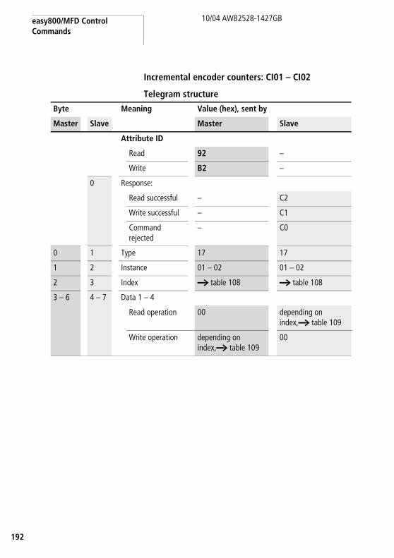
easy800/MFD Control Commands
192
10/04 AWB2528-1427GB
Incremental encoder counters: CI01 – CI02
Telegram structure
Byte Meaning Value (hex), sent by
Master Slave Master Slave
Attribute ID
Read 92 –
Write B2 –
0 Response:
Read successful – C2
Write successful – C1
Command rejected
– C0
0 1 Type 17 17
1 2 Instance 01 – 02 01 – 02
2 3 Index a table 108 a table 108
3 – 6 4 – 7 Data 1 – 4
Read operation 00 depending on index,a table 109
Write operation depending on index,a table 109
00

Read/write function block data
93
10/04 AWB2528-1427GB
1
Table 108: Operand overview0
Table 109: Index 0 – Bit IO
Index (hex)
Operand Value read write
00 Bit IO a table 109 x
01 Mode/Parameter – – –
02 Upper setpoint SH In integer range from –2147483648 to +2147483647
x c1
03 Lower setpoint SL x c1
04 Preset actual value SV x c1
05 Actual value in Run mode
QV x
1) The value can only be written if it is assigned to a constant in the program.
h The data for index 2 to 5 is transferred as a 32-bit value in Intel format (Data 1 – Low Byte to Data 4 – High Byte).
Bit 7 6 5 4 3 2 1 0
FB input Data 1 – – – – – EN1 SE2 RE3
FB output Data 3 – – – – ZE4 CY5 FB6 OF7
1) Counter enable2) Transfer preset actual value on rising edge3) Reset actual value to zero4) Zero: Status 1 if the value of the function block output QV (the
counter status) equals zero5) Carry: Status 1 if the value range is exceeded6) Fall below: Status 1 if the actual value F lower setpoint7) Overflow: Status 1 if the actual value f lower setpoint

easy800/MFD Control Commands
194
10/04 AWB2528-1427GB
Comparator: CP01 – CP32
Telegram structure
Byte Meaning Value (hex), sent by
Master Slave Master Slave
Attribute ID
Read 92 –
Write B2 –
0 Response:
Read successful – C2
Write successful – C1
Command rejected
– C0
0 1 Type 18 18
1 2 Instance 01 – 20 01 – 20
2 3 Index a table 110 a table 110
3 – 6 4 – 7 Data 1 – 4
Read operation 00 depending on index,a table 111
Write operation depending on index,a table 111
00

Read/write function block data
95
10/04 AWB2528-1427GB
1
Table 110: Operand overview
Table 111: Index 0 – Bit IO
Index (hex)
Operand read write
00 Bit IO, a table 111 x
01 Mode/Parameter – –
02 Comparison value I1 x c1
03 Comparison value I2 x c1
1) The value can only be written if it is assigned to a constant in the program.
h The data for index 2 and 3 is transferred as a 32-bit value in Intel format (Data 1 – Low Byte to Data 4 – High Byte).
Bit 7 6 5 4 3 2 1
FB output Data 3 – – – – GT1 EQ2 LT3
1) greater than: Status 1 if the value at I1 is greater than value at I2 (I1 > I2)
2) equal: Status 1 if the value at I1 is equal to value at I2 (I1 = I2) 3) less than: Status 1 if the value at I1 is less than value at I2
(I1 < I2)

easy800/MFD Control Commands
196
10/04 AWB2528-1427GB
Text output function block: D01 – D32
Telegram structure
Byte Meaning Value (hex), sent by
Master Slave Master Slave
Attribute ID
Read 92 –
Write B2 –
0 Response:
Read successful – C2
Write successful – C1
Command rejected
– C0
0 1 Type 19 19
1 2 Instance 01 – 20 01 – 20
2 3 Index a table 112 a table 112
3 – 6 4 – 7 Data 1 – 4
Read operation 00 depending on index,a table 113
Write operation depending on index,a table 113
00

Read/write function block data
97
10/04 AWB2528-1427GB
1
Table 112: Operand overview
Index (hex)
Operand read write
00 Bit IO, a table 113 x
01 Mode/Parameter – –
02 Text line 1, column 1 - 4 x
03 Text line 1, column 5 - 8 x
04 Text line 1, column 9 - 12 x
05 Text line 1, column 13 - 16 x
06 Text line 2, column 1 - 4 x
07 Text line 2, column 5 - 8 x
08 Text line 2, column 9 - 12 x
09 Text line 2, column 13 - 16 x
10 Text line 3, column 1 - 4 x
11 Text line 3, column 5 - 8 x
12 Text line 3, column 9 - 12 x
13 Text line 3, column 13 - 16 x
14 Text line 4, column 1 - 4 x
15 Text line 4, column 5 - 8 x
16 Text line 4, column 9 - 12 x
17 Text line 4, column 13 - 16 x
18 Variable 1 x c1
19 Variable 2 x c1
20 Variable 3 x c1
21 Variable 4 x c1
22 Scaling minimum value 1 x
23 Scaling minimum value 2 x
24 Scaling minimum value 3 x
25 Scaling minimum value 4 x
26 Scaling maximum value 1 x
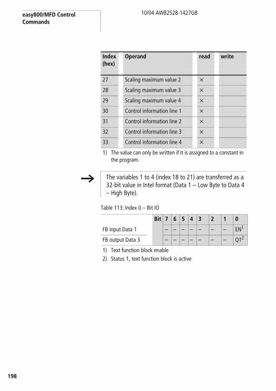
easy800/MFD Control Commands
198
10/04 AWB2528-1427GB
Table 113: Index 0 – Bit IO
27 Scaling maximum value 2 x
28 Scaling maximum value 3 x
29 Scaling maximum value 4 x
30 Control information line 1 x
31 Control information line 2 x
32 Control information line 3 x
33 Control information line 4 x
1) The value can only be written if it is assigned to a constant in the program.
Index (hex)
Operand read write
h The variables 1 to 4 (index 18 to 21) are transferred as a 32-bit value in Intel format (Data 1 – Low Byte to Data 4 – High Byte).
Bit 7 6 5 4 3 2 1 0
FB input Data 1 – – – – – – – EN1
FB output Data 3 – – – – – – – Q12
1) Text function block enable2) Status 1, text function block is active

Read/write function block data
99
10/04 AWB2528-1427GB
1
Data block: DB01 – DB32
Telegram structure
Byte Meaning Value (hex), sent by
Master Slave Master Slave
Attribute ID
Read 92 –
Write B2 –
0 Response:
Read successful – C2
Write successful – C1
Command rejected
– C0
0 1 Type 1A 1A
1 2 Instance 01 – 20 01 – 20
2 3 Index a table 114 a table 114
3 – 6 4 – 7 Data 1 – 4
Read operation 00 depending on index,a table 115
Write operation depending on index,a table 115
00

easy800/MFD Control Commands
200
10/04 AWB2528-1427GB
Table 114: Operand overview
Table 115: Index 0 – Bit IO
Index (hex)
Operand read write
00 Bit IO, a table 115 x
01 Mode/Parameter – –
02 Input value: value that is transferred to the QV output when the FB is triggered.
I1 x c1
03 Output value QV x
1) The value can only be written if it is assigned to a constant in the program.
h The data for index 2 and 3 is transferred as a 32-bit value in Intel format (Data 1 – Low Byte to Data 4 – High Byte).
Bit 7 6 5 4 3 2 1 0
FB input Data 1 – – – – – – – T1
FB output Data 3 – – – – – – – Q12
1) Transfer of the value present at I1 on rising edge.2) Status 1 if the trigger signal is 1.

Read/write function block data
01
10/04 AWB2528-1427GB
2
PID controller: DC01 – DC32
Telegram structure
Byte Meaning Value (hex), sent by
Master Slave Master Slave
Attribute ID
Read 92 –
Write B2 –
0 Response:
Read successful – C2
Write successful – C1
Command rejected
– C0
0 1 Type 27 27
1 2 Instance 01 – 20 01 – 20
2 3 Index a table 116 a table 116
3 – 6 4 – 7 Data 1 – 4
Read operation 00 depending on index, a table 117, 118
Write operation depending on index, a table 117, 118

easy800/MFD Control Commands
202
10/04 AWB2528-1427GB
Table 116: Operand overview
Index (hex)
Operand read write
00 Bit IO, a table 117 x
01 Mode, a table 118 x
02 Setpoint: –32768 to +32767 I1 x c1
03 Actual value: –32768 to +32767 I2 x c1
04 Proportional gain[%], Value range: 0 to 65535
KP x c1
05 Reset time [0.1 s], Value range: 0 to 65535 TN x c1
06 Rate time [0.1 s], Value range: 0 to 65535 TV x c1
07 Scan time = Time between function block calls. Value range: 0.1s to 6553.5s. If 0 is entered as the value, the scan time will be determined by the program cycle time.
TC x c1
08 Manual manipulated variable, value range: –4096 to +4095
MV x c1
09 Manipulated variable QV x
• Mode: UNI, value range: 0 to +4095 (12 bit)• Mode: BIP, value range: –4096 to +4095 (13 bit)
1) The value can only be written if it is assigned to a constant in the program.
h The data for index 2 to 9 is transferred as a 32-bit value in Intel format (Data 1 – Low Byte .. Data 2 - High Byte).

Read/write function block data
03
10/04 AWB2528-1427GB
2
Table 117: Index 0 – Bit IO
Table 118: Index 1 - Mode
Bit 7 6 5 4 3 2 1 0
FB input Data 1 – – – SE1 ED2 EI3 EP4 EN5
FB output Data 3 – – – – – – – LI6
1) Transfer of manual manipulated variable on status 12) Activation of D component on status 13) Activation of I component on status 14) Activation of P component on status 15) Activates the function block on status 1.6) Status 1 if the value range of the medium-voltage was
exceeded
Data 1 Mode
UNP unipolar
The manipulated variable is output as a unipolar 12-bit value. Corresponding value range for QV 0 to 4095.
BIP bipolar
The manipulated variable is output as a bipolar 13-bit value. Corresponding value range for QV –4096 to 4095

easy800/MFD Control Commands
204
10/04 AWB2528-1427GB
Signal smoothing filter: FT01 – FT32
Telegram structure
Byte Meaning Value (hex), sent by
Master Slave Master Slave
Attribute ID
Read 92 –
Write B2 –
0 Response:
Read successful – C2
Write successful – C1
Command rejected
– C0
0 1 Type 28 28
1 2 Instance 01 – 20 01 – 20
2 3 Index a table 119 a table 119
3 – 6 4 – 7 Data 1 – 4
Read operation 00 depending on index,a table 120
Write operation depending on index,a table 120
00

Read/write function block data
05
10/04 AWB2528-1427GB
2
Table 119: Operand overview
Table 120: Index 0 – Bit IO
Index (hex)
Operand read write
00 Bit IO, a table 120 x
01 Mode/Parameter – –
02 Input value, value range: –32768 to +32767 I1 x c1
03 Recovery time [0.1 s], Value range: 0 to 65535 TG x c1
04 Proportional gain [%], Value range: 0 to 65535 KP x c1
05 Delayed output value, value range: –32768 to +32767
QV x
1) The value can only be written if it is assigned to a constant in the program.
Bit 7 6 5 4 3 2 1 0
FB output Data 3 – – – – – – – EN1
1) Activates the function block on status 1.
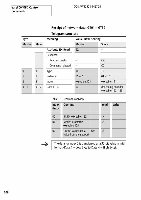
easy800/MFD Control Commands
206
10/04 AWB2528-1427GB
Receipt of network data: GT01 – GT32
Telegram structure
Table 121: Operand overview
Byte Meaning Value (hex), sent by
Master Slave Master Slave
Attribute ID: Read 92 –
0 Response:
Read successful – C2
Command rejected – C0
0 1 Type 1B 1B
1 2 Instance 01 – 20 01 – 20
2 3 Index a table 121 a table 121
3 – 6 4 – 7 Data 1 – 4 00 depending on index, a table 122, 123
Index (hex)
Operand read write
00 Bit IO, a table 122 x
01 Mode/Parameters, a table 123
x –
02 Output value: actual value from the network
QV x
h The data for index 2 is transferred as a 32-bit value in Intel format (Data 1 – Low Byte to Data 4 – High Byte).
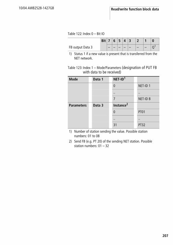
Read/write function block data
07
10/04 AWB2528-1427GB
2
Table 122: Index 0 – Bit IO
Table 123: Index 1 – Mode/Parameters (designation of PUT FB with data to be received)
Bit 7 6 5 4 3 2 1 0
FB output Data 3 – – – – – – – Q1
1) Status 1 if a new value is present that is transferred from the NET network.
Mode Data 1 NET-ID1
0 NET-ID 1
.. ..
7 NET-ID 8
Parameters Data 3 Instance2
0 PT01
.. ..
31 PT32
1) Number of station sending the value. Possible station numbers: 01 to 08
2) Send FB (e.g. PT 20) of the sending NET station. Possible station numbers: 01 – 32

easy800/MFD Control Commands
208
10/04 AWB2528-1427GB
7-day time switch: HW01 – HW32
Telegram structure
Table 124: Operand overview
Byte Meaning Value (hex), sent by
Master Slave Master Slave
Attribute ID: Read 92 –
0 Response:
Read successful – C2
Command rejected – C0
0 1 Type 1C 1C
1 2 Instance 01 – 20 01 – 20
2 3 Index a table 124 a table 124
3 – 6 4 – 7 Data 1 – 4 00 depending on index,a table 125
Index (hex)
Operand read write
00 Bit IO a table 125 x
01 Mode/Parameter – –
02 Parameters a table 126 x
Channel A
03 Channel B
04 Channel C
05 Channel D

Read/write function block data
09
10/04 AWB2528-1427GB
2
Table 125: Index 0 – Bit IO
The data in the following table is shown in the Motorola format although it is actually transferred in Intel format.
Table 126: Index 2 – 5, Parameter channels A – D
Bit 7 6 5 4 3 2 1 0
FB output Data 3 – – – – – – – Q1
1) Status 1 if the switch-on condition is fulfilled.
Bit 7 6 5 4 3 2 1 0 7 6 5 4 3 2 1 0
Date 2 Date 1
ON d4 d3 d2 d1 d0 h4 h3 h2 h1 h0 m5 m4 m3 m2 m1 m0
Weekday Hour Minute
Bit 7 6 5 4 3 2 1 0 7 6 5 4 3 2 1 0
Date 4 Date 3
OFF d4 d3 d2 d1 d0 h4 h3 h2 h1 h0 m5 m4 m3 m2 m1 m0
Weekday Hour Minute
m5 to m0: Minute (0 to 59)h4 to h0: Hour (0 to 23)d5 to d0: Weekday (0 = Sunday to 6 = Saturday)
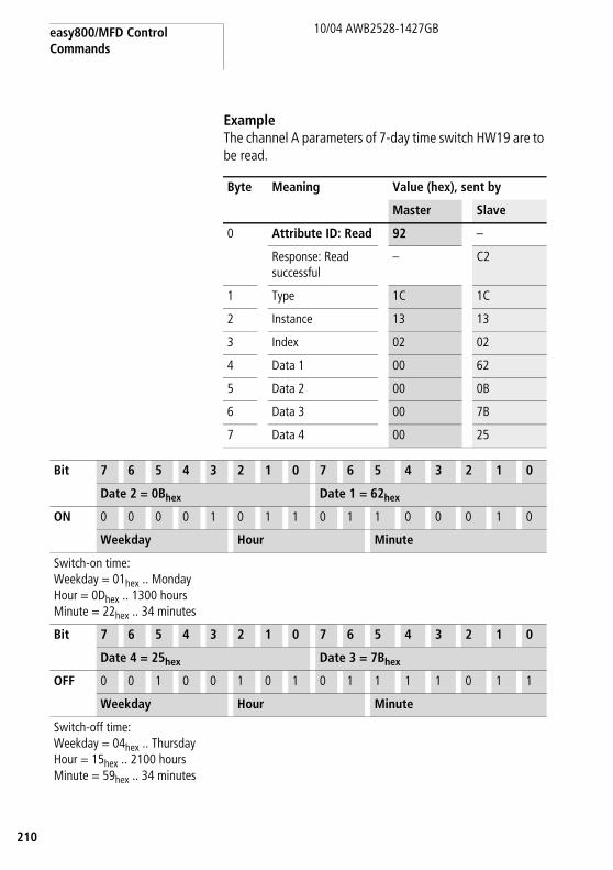
easy800/MFD Control Commands
210
10/04 AWB2528-1427GB
Example The channel A parameters of 7-day time switch HW19 are to be read.
Byte Meaning Value (hex), sent by
Master Slave
0 Attribute ID: Read 92 –
Response: Readsuccessful
– C2
1 Type 1C 1C
2 Instance 13 13
3 Index 02 02
4 Data 1 00 62
5 Data 2 00 0B
6 Data 3 00 7B
7 Data 4 00 25
Bit 7 6 5 4 3 2 1 0 7 6 5 4 3 2 1 0
Date 2 = 0Bhex Date 1 = 62hex
ON 0 0 0 0 1 0 1 1 0 1 1 0 0 0 1 0
Weekday Hour Minute
Switch-on time:Weekday = 01hex .. MondayHour = 0Dhex .. 1300 hoursMinute = 22hex .. 34 minutes
Bit 7 6 5 4 3 2 1 0 7 6 5 4 3 2 1 0
Date 4 = 25hex Date 3 = 7Bhex
OFF 0 0 1 0 0 1 0 1 0 1 1 1 1 0 1 1
Weekday Hour Minute
Switch-off time:Weekday = 04hex .. ThursdayHour = 15hex .. 2100 hoursMinute = 59hex .. 34 minutes

Read/write function block data
11
10/04 AWB2528-1427GB
2
Year time switch: HY01 – HY32
Telegram structure
Table 127: Operand overview
Byte Meaning Value (hex), sent by
Master Slave Master Slave
Attribute ID: Read
92 –
0 Response:
Read successful – C2
Command rejected
– C0
0 1 Type 1D 1D
1 2 Instance 01 – 20 01 – 20
2 3 Index a table 127 a table 127
3 – 6 4 – 7 Data 1 – 4 00 depending on index,a table 128
Index (hex)
Operand read write
00 Bit IO a table 128 x
01 Mode/Parameter – –
02 Parameters a table 129 x
Channel A
03 Channel B
04 Channel C
05 Channel D

easy800/MFD Control Commands
212
10/04 AWB2528-1427GB
Table 128: Index 0 – Bit IO
The data in the following table is shown in the Motorola format although it is actually transferred in Intel format.
Table 129: Index 2 – 5, Parameter channels A – D
Example The channel A parameters of year time switch HY14 are to be written.
Bit 7 6 5 4 3 2 1 0
FB output Data 3 – – – – – – – Q1
1) Status 1 if the switch-on condition is fulfilled.
Bit 7 6 5 4 3 2 1 0 7 6 5 4 3 2 1 0
Date 2 Date 1
ON y6 y5 y4 y3 y2 y1 y0 m3 m2 m1 m0 d4 d3 d2 d1 d0
Year Month Day
Bit 7 6 5 4 3 2 1 0 7 6 5 4 3 2 1 0
Date 4 Date 3
OFF y6 y5 y4 y3 y2 y1 y0 m3 m2 m1 m0 d4 d3 d2 d1 d0
Year Month Day
d4 ... d0: Day (1 .. 31), m3 ... m0: Month (1 .. 12), y6 ... y0: Year (0: 2000 .. 99: 2099)
Index 2 – 5, Parameter channels A – D
Bit 7 6 5 4 3 2 1 0 7 6 5 4 3 2 1 0
Date 2 Date 1
ON 0 0 0 0 0 1 1 0 1 1 0 0 1 1 1 0
Year Month Day
Switch-on time:Day = 14 = 0Ehex = 0000 1110binMonth = 6 (June) = 06hex = 0000 0110binYear = 2003 = 03hex = 0000 0011bin
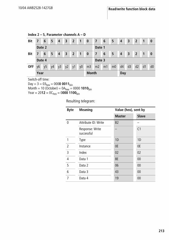
Read/write function block data
13
10/04 AWB2528-1427GB
2
Resulting telegram:
Bit 7 6 5 4 3 2 1 0 7 6 5 4 3 2 1 0
Date 4 Date 3
OFF y6 y5 y4 y3 y2 y1 y0 m3 m2 m1 m0 d4 d3 d2 d1 d0
Year Month Day
Switch-off time:Day = 3 = 03hex = 0000 0011binMonth = 10 (October) = 0Ahex = 0000 1010binYear = 2012 = 0Chex = 0000 1100bin
Index 2 – 5, Parameter channels A – D
Bit 7 6 5 4 3 2 1 0 7 6 5 4 3 2 1 0
Date 2 Date 1
Byte Meaning Value (hex), sent by
Master Slave
0 Attribute ID: Write B2 –
Response: Writesuccessful
– C1
1 Type 1D 1D
2 Instance 0E 0E
3 Index 02 02
4 Data 1 8E 00
5 Data 2 06 00
6 Data 3 43 00
7 Data 4 19 00

easy800/MFD Control Commands
214
10/04 AWB2528-1427GB
Value scaling: LS01 – LS32
Telegram structure
Byte Meaning Value (hex), sent by
Master Slave Master Slave
Attribute ID
Read 92 –
Write B2 –
0 Response:
Read successful – C2
Write successful – C1
Command rejected
– C0
0 1 Type 29 29
1 2 Instance 01 – 20 01 – 20
2 3 Index a table 130 a table 130
3 – 6 4 – 7 Data 1 – 4
Read operation 00 depending on index,a table 131
Write operation depending on index,a table 131

Read/write function block data
15
10/04 AWB2528-1427GB
2
Table 130: Operand overview
Table 131: Index 0 – Bit IO
Index (hex)
Operand read write
00 Bit IO, a table 131 x
01 Mode/Parameter – –
02 Input value, value range: 32 bit
I1 x c1
03 Interpolation point 1,X co-ordinate, value range: 32 bit
X1 x c1
04 Interpolation point 1, Y co-ordinate, value range: 32 bit
Y1 x c1
05 Interpolation point 2, X co-ordinate, value range: 32 bit
X2 x c1
06 Interpolation point 2, Y co-ordinate, value range: 32 bit
Y2 x c1
07 Output value: contains the scaled input value
QV x
1) The value can only be written if it is assigned to a constant in the program.
Bit 7 6 5 4 3 2 1 0
FB output Data 3 – – – – – – – EN1
1) Activates the function block on status 1.

easy800/MFD Control Commands
216
10/04 AWB2528-1427GB
Master reset: MR01 – MR32
Telegram structure
Byte Meaning Value (hex), sent by
Master Slave Master Slave
Attribute ID: Read 92 –
0 Response:
Read successful – C2
Command rejected – C0
0 1 Type 0F 0F
1 2 Instance 01 – 20 01 – 20
2 3 Index
Bit IO 00 00
Mode 01 01
3 – 6 4 – 7 Data 1 – 4 00 depending on index, a table 132, 133

Read/write function block data
17
10/04 AWB2528-1427GB
2
Table 132: Index 0 – Bit IO
Table 133: Index 1 - Mode
Bit 7 6 5 4 3 2 1 0
FB input Data 1 – – – – – – – T1
FB output Data 3 – – – – – – – Q12
1) Trigger coil. The appropriate Reset is executed if the coil is triggered (with a rising edge).
2) Status 1 if the trigger coil MR..T is 1.
Data 1 (hex)
00 Q Outputs Q.., *Q.., S.., *S.., *SN.., QA01 are reset to 0. * depending on the NET-ID
01 m The marker range MD01 to MD48 is reset to 0.
02 ALL Has an effect on Q and M.

easy800/MFD Control Commands
218
10/04 AWB2528-1427GB
Numerical converter: NC01 – NC32
Telegram structure
Byte Meaning Value (hex), sent by
Master Slave Master Slave
Attribute ID
Read 92 –
Write B2 –
0 Response:
Read successful – C2
Write successful – C1
Command rejected
– C0
0 1 Type A 2 A 2
1 2 Instance 01 – 20 01 – 20
2 3 Index a table 134 a table 134
3 – 6 4 – 7 Data 1 – 4
Read operation 00 depending on index, a table 135, 136
Write operation depending on index, a table 135, 136
00
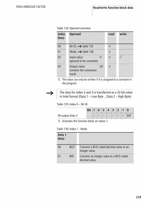
Read/write function block data
19
10/04 AWB2528-1427GB
2
Table 134: Operand overview
Table 135: Index 0 – Bit IO
Table 136: Index 1 - Mode
Index (hex)
Operand read write
00 Bit IO, a table 135 x
01 Mode, a table 136 x
02 Input value: operand to be converted
I1 x c1
03 Output value: contains the conversion result
QV x
1) The value can only be written if it is assigned to a constant in the program.
h The data for index 2 and 3 is transferred as a 32-bit value in Intel format (Data 1 – Low Byte .. Data 2 - High Byte).
Bit 7 6 5 4 3 2 1 0
FB output Data 3 – – – – – – – EN1
1) Activates the function block on status 1.
Data 1 (hex)
00 BCD Converts a BCD coded decimal value to an integer value.
01 BIN Converts an integer value to a BCD coded decimal value.

easy800/MFD Control Commands
220
10/04 AWB2528-1427GB
Hours-run meters: OT01 – OT04
Telegram structure
h Further information is available in the S40 Application Note AN27K21g.exe “EASY800/MFD-DP Data Handling Function Block for PS416 and PS4-341”.
Byte Meaning Value (hex), sent by
Master Slave Master Slave
Attribute ID
Read 92 –
Write B2 –
0 Response:
Read successful – C2
Write successful – C1
Command rejected
– C0
0 1 Type 1E 1E
1 2 Instance 01 – 04 01 – 04
2 3 Index a table 137 a table 137
3 – 6 4 – 7 Data 1 – 4
Read operation 00 depending on index,a table 138
Write operation depending on index,a table 138
00

Read/write function block data
21
10/04 AWB2528-1427GB
2
Table 137: Operand overview
Table 138: Index 0 – Bit IO
Index (hex)
Operand read write
00 Bit IO, a table 138 x
01 Mode/Parameter – –
02 Upper threshold value I1 x c1
03 Actual value of operating hours counter
QV x
1) The value can only be written if it is assigned to a constant in the program.
Bit 7 6 5 4 3 2 1 0
FB input Data 1 – – – – – – RE1 EN2
FB output Data 3 – – – – – – – Q13
1) Reset coil: Status 1 resets the counter actual value to zero.2) Enable coil3) Status 1 if the setpoint was reached (greater than/equal to)
h The data for index 2 and 3 is transferred as a 32-bit value in Intel format (Data 1 – Low Byte to Data 4 – High Byte).

easy800/MFD Control Commands
222
10/04 AWB2528-1427GB
Sending of network data: PT01 – PT32
Telegram structure
Table 139: Operand overview
Byte Meaning Value (hex), sent by
Master Slave Master Slave
Attribute ID: Read 92 –
0 Response:
Read successful – C2
Command rejected – C0
0 1 Type 1F 1F
1 2 Instance 01 – 20 01 – 20
2 3 Index a table 139 a table 139
3 – 6 4 – 7 Data 1 – 4 00 depending on index,a table 140
Index (hex)
Operand read write
00 Bit IO, a table 140 x
01 Mode/Parameter – –
02 Input value: Setpoint that it transmitted to the NET network
I1 x
h The data for index 2 is transferred as a 32-bit value in Intel format (Data 1 – Low Byte to Data 4 – High Byte).

Read/write function block data
23
10/04 AWB2528-1427GB
2
Table 140: Index 0 – Bit IO
Bit 7 6 5 4 3 2 1 0
FB input Data 1 – – – – – – – T1
FB output Data 3 – – – – – – – Q12
1) Trigger coil. The value is provided on the NET if the coil is triggered (with a rising edge).
2) Status 1 if the trigger coil PT..T_ is also 1.

easy800/MFD Control Commands
224
10/04 AWB2528-1427GB
Pulse width modulation: PW01 – PW02
Telegram structure
Byte Meaning Value (hex), sent by
Master Slave Master Slave
Attribute ID
Read 92 –
Write B2 –
0 Response:
Read successful – C2
Write successful – C1
Command rejected
– C0
0 1 Type 2B 2B
1 2 Instance 01 – 02 01 – 02
2 3 Index a table 141 a table 141
3 – 6 4 – 7 Data 1 – 4
Read operation 00 depending on index,a table 142
Write operation depending on index,a table 142
00

Read/write function block data
25
10/04 AWB2528-1427GB
2
Table 141: Operand overview
Table 142: Index 0 – Bit IO
Index (hex)
Operand read write
00 Bit IO, a table 142 x
01 Mode/Parameter – –
02 Manipulated variable, value range: 0 to 4095 (12 bit) SV x c1
03 Period duration [ms], Value range: 0 to 65535 PD x c1
04 Minimum on duration [ms], Value range: 0 to 65535 ME x c1
1) The value can only be written if it is assigned to a constant in the program.
Bit 7 6 5 4 3 2 1 0
FB input Data 1 – – – – – – – EN1
FB output Data 3 – – – – – – – E12
1) Activates the function block on status 1.2) Status 1 if below the minimum on duration or minimum off
duration

easy800/MFD Control Commands
226
10/04 AWB2528-1427GB
Synchronize clock function block: SC01
Telegram structure
Table 143: Operand overview
Table 144: Index 0 – Bit IO
Byte Meaning Value (hex), sent by
Master Slave Master Slave
Attribute ID: Read 92 –
0 Response:
Read successful – C2
Command rejected – C0
0 1 Type 20 20
1 2 Instance 01 01
2 3 Index a table 143 a table 143
3 – 6 4 – 7 Data 1 – 4 00 depending on index,a table 144
Index (hex)
Operand read write
00 Bit IO, a table 144 x
01 Mode/Parameter – –
Bit 7 6 5 4 3 2 1 0
FB input Data 1 – – – – – – – T1
FB output Data 3 – – – – – – – Q12
1) Trigger coil. If the coil is triggered (rising edge), the current date, weekday and time of the sending station are automatically sent to the NET network.
2) Status 1 if the trigger coil SC01T_ is also 1.

Read/write function block data
27
10/04 AWB2528-1427GB
2
Set cycle time function block: ST01
Telegram structure
Byte Meaning Value (hex), sent by
Master Slave Master Slave
Attribute ID
Read 92 –
Write B2 –
0 Response:
Read successful – C2
Write successful – C1
Command rejected
– C0
0 1 Type 2C 2C
1 2 Instance 01 01
2 3 Index a table 145 a table 145
3 – 6 4 – 7 Data 1 – 4
Read operation 00 depending on index,a table 146
Write operation depending on index,a table 146
00

easy800/MFD Control Commands
228
10/04 AWB2528-1427GB
Table 145: Operand overview
Table 146: Index 0 – Bit IO
Index (hex)
Operand read write
00 Bit IO, a table 146 x
01 Mode/Parameter – –
02 Cycle time in ms, value range: 0 – 1000
I1 x c1
1) The value can only be written if it is assigned to a constant in the program.
Bit 7 6 5 4 3 2 1 0
FB output Data 3 – – – – – – – EN1
1) Activates the function block on status 1.

Read/write function block data
29
10/04 AWB2528-1427GB
2
Timing relays: T01 – T32
Telegram structure
Byte Meaning Value (hex), sent by
Master Slave Master Slave
Attribute ID
Read 92 –
Write B2 –
0 Response:
Read successful – C2
Write successful – C1
Command rejected
– C0
0 1 Type 21 21
1 2 Instance 01 – 20 01 – 20
2 3 Index a table 147 a table 147
3 – 6 4 – 7 Data 1 – 4
Read operation 00 depending on index, a table 148, 149
Write operation depending on index, a table 148, 149

easy800/MFD Control Commands
230
10/04 AWB2528-1427GB
Table 147: Operand overview
Table 148: Index 0 – Bit IO
Index (hex)
Operand read write
00 Bit IO, a table 148 x
01 Mode/Parameters, a table 149
x
02 Setpoint 1:Time setpoint 1
I1 x c1
03 Setpoint 2:Time setpoint 2 (with timing relay with 2 setpoints)
I2 x c1
04 Actual value:Time elapsed in Run mode
QV x
1) The value can only be written if it is assigned to a constant in the program.
h The data for index 2 to 4 is transferred as a 32-bit value in Intel format (Data 1 – Low Byte to Data 4 – High Byte).
Bit 7 6 5 4 3 2 1 0
FB input Data 1 – – – – – ST1 EN2 RE3
FB output Data 3 – – – – – – – Q14
1) Stop, the timing relay is stopped (Stop coil)2) Enable, the timing relay is started (trigger coil)3) Reset, the timing relay is reset (reset coil)4) Switch contact

Read/write function block data
31
10/04 AWB2528-1427GB
2
Table 149: Index 1 - Mode/Parameters
Mode Data 1 Mode
0 On-delayed,
1 On-delayed with random setpoint
2 off-delayed.
3 Off-delayed with random setpoint
4 On and off delayed (two time setpoints)
5 On and off delayed each with random setpoint (two time setpoints)
6 Impulse transmitter
7 Flashing relay (two time setpoints)
8 Off-delayed, retriggerable (easy600 Mode)
9 Off-delayed with random setpoint, retriggerable (easy600 Mode)
Parameters
Data 3 Mode
0 S (milliseconds)
1 M:S (seconds)
2 H:M (minutes)
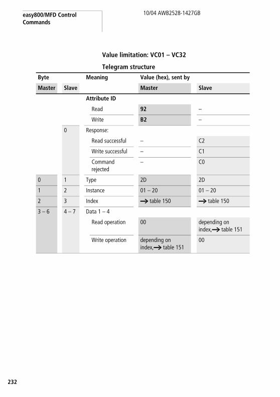
easy800/MFD Control Commands
232
10/04 AWB2528-1427GB
Value limitation: VC01 – VC32
Telegram structure
Byte Meaning Value (hex), sent by
Master Slave Master Slave
Attribute ID
Read 92 –
Write B2 –
0 Response:
Read successful – C2
Write successful – C1
Command rejected
– C0
0 1 Type 2D 2D
1 2 Instance 01 – 20 01 – 20
2 3 Index a table 150 a table 150
3 – 6 4 – 7 Data 1 – 4
Read operation 00 depending on index,a table 151
Write operation depending on index,a table 151
00

Read/write function block data
33
10/04 AWB2528-1427GB
2
Table 150: Operand overview
Table 151: Index 0 – Bit IO
Index (hex)
Operand read write
00 Bit IO, a table 151 x
01 Mode/Parameter – –
02 Input value I1 x c1
03 Upper limit value SH x c1
04 Lower limit value SL x c1
05 Output value: outputs the value present at input I1 within the set limits.
QV x
1) The value can only be written if it is assigned to a constant in the program.
Bit 7 6 5 4 3 2 1 0
FB output Data 3 – – – – – – – EN1
1) Activates the function block on status 1.
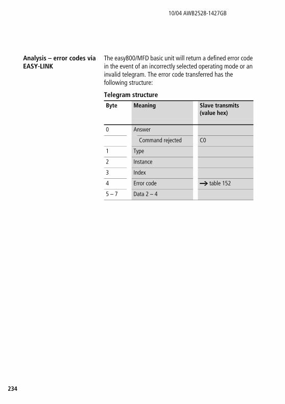
234
10/04 AWB2528-1427GB
Analysis – error codes via EASY-LINK
The easy800/MFD basic unit will return a defined error code in the event of an incorrectly selected operating mode or an invalid telegram. The error code transferred has the following structure:
Telegram structure
Byte Meaning Slave transmits (value hex)
0 Answer
Command rejected C0
1 Type
2 Instance
3 Index
4 Error code a table 152
5 – 7 Data 2 – 4

Analysis – error codes via EASY-LINK
35
10/04 AWB2528-1427GB
2
Table 152: Error codes
Error code
Description
0x00 no error
0x03 formal fault in the response relating to type, instance or index
0x04 no communication possible (timeout)
0x05 DP module has only sent 0xC0 (Easy800 Basic II, MFD version I).
0x45 the value selected by the type and index may not be written (bit IO, mode/parameter or output value).
0x46 the value selected by the type and index is not assigned with a constant.
0x9E access to the FB data not possible (program download active).
0x9F type is invalid (no defined FB, also dependant on the version of the addressed device).
0xA0 FB selected by type and instance does not exist in program.
0xA1 index relative to the defined FB type is invalid

236
10/04 AWB2528-1427GB

37
10/04 AWB2528-1427GB
2
9 What happens if...?
Module Status LED MS
Possible cause To correct or avoid error
OFF No power at EASY222-DN. Switch on the power supply.
Green EASY222-DN is in standby mode. None
Green flashing EASY222-DN not configured. Verify the correct setting of the MAC ID.
Red flashing Invalid configuration Check configuration data.
RED Module error which can not be resolved. Replace the EASY222-DN.
Network Status LED NS
Possible cause To correct or avoid error
OFF • EASY222-DN without power or • communication is blocked at this
channel because – of bus-off state or – power loss or– the channel was blocked explicitly.
• Switch on the EASY222-DN,• supply the mains voltage to
the channel and • ensure that the channel is
active.
Green Although the channel is enabled, communication is not possible.
Check the communication function at the master PLC.
Green flashing Normal mode None
Red flashing Communication error or the EASY222-DN may be defective.
Reset the module. If further errors occur, replace the EASY222-DN.
RED Communication error. Check the master PLC.

238
10/04 AWB2528-1427GB

39
10/04 AWB2528-1427GB
2
Annex
Technical Data
General
Standards and regulations EN 61000-6-1; EN 61000-6-2; EN 61000-6-3; EN 61000-6-4, IEC 60068-2-27, IEC 50178
Dimensions W x H x D mm 35.5 x 90 x 56.5
Weight g 150
Mounting DIN 50022 rail, 35 mmscrew fixing with fixing bracket ZB4-101-GF1 (accessories)
Climatic environmental conditions (Cold to IEC 60068-2-1, Heat to IEC 60068-2-2)
Ambient temperatureInstalled horizontally/vertically
°C –25 to +55
Condensation Prevent condensation with suitable measures
Storage/transport temperature °C –40 to +70
Relative humidity (IEC 60068-2-30), no moisture condensation
% 5 to 95
Air pressure (operation) hPa 795 to 1080
Corrosion resistance (IEC 60068-2-42, IEC 60068-2-43)
SO2 10 cm3 /m3, 4 daysH2S 1 cm3 /m3, 4 days
Mechanical ambient conditions
Pollution degree 2
Degree of protection (EN 50178, IEC 60529, VBG4)
IP20
Vibration (IEC 60068-2-6)
constant amplitude 0.15 mm Hz 10 to 57
constant acceleration 2 g Hz 57 to 150
Shocks (IEC 60068-2-27) semi-sinusoidal 15 g/11 ms
Shocks 18
Drop (IEC 60068-2-31) height mm 50
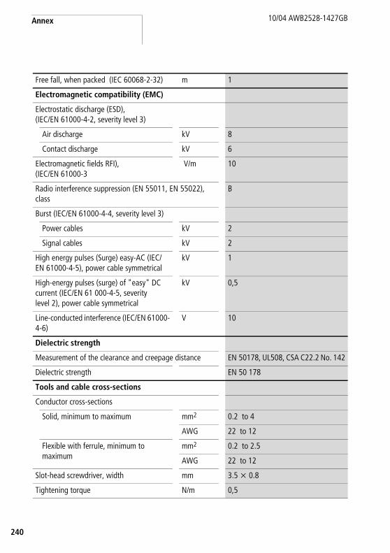
Annex
240
10/04 AWB2528-1427GB
Free fall, when packed (IEC 60068-2-32) m 1
Electromagnetic compatibility (EMC)
Electrostatic discharge (ESD),(IEC/EN 61000-4-2, severity level 3)
Air discharge kV 8
Contact discharge kV 6
Electromagnetic fields RFI), (IEC/EN 61000-3
V/m 10
Radio interference suppression (EN 55011, EN 55022), class
B
Burst (IEC/EN 61000-4-4, severity level 3)
Power cables kV 2
Signal cables kV 2
High energy pulses (Surge) easy-AC (IEC/EN 61000-4-5), power cable symmetrical
kV 1
High-energy pulses (surge) of "easy" DC current (IEC/EN 61 000-4-5, severity level 2), power cable symmetrical
kV 0,5
Line-conducted interference (IEC/EN 61000-4-6)
V 10
Dielectric strength
Measurement of the clearance and creepage distance EN 50178, UL508, CSA C22.2 No. 142
Dielectric strength EN 50 178
Tools and cable cross-sections
Conductor cross-sections
Solid, minimum to maximum mm2 0.2 to 4
AWG 22 to 12
Flexible with ferrule, minimum to maximum
mm2 0.2 to 2.5
AWG 22 to 12
Slot-head screwdriver, width mm 3.5 x 0.8
Tightening torque N/m 0,5

Technical Data
41
10/04 AWB2528-1427GB
2
Power supply
Rated voltage
Rated value V DC 24 (–15, +20)
Permissible range V DC 20.4 to 28.8
Residual ripple % < 5
Input current at 24 V DC, typical mA 200
Voltage dips, IEC/EN 61131-2 ms 10
Power loss at 24 V DC, typical W 4,8
LED displays
Module Status LED MS Colour Green/red
Network Status LED NS Colour Green/red
DeviceNet
Device connection 5-pole socket
Electrical isolation Bus to power supply (simple)Bus and power supply to easy basic unit (safety isolation)
Function DeviceNetSlave
INTERFACE DeviceNet (CAN)
Bus protocol DeviceNet
Baud rate, automatic detection up to kbps 500
Bus termination resistors Separate installation at the bus possible
Bus addresses, accessible via easy basic unit with display or EASY-SOFT
0 to 63
Services
Module inputs all data S1 to S8 (easy600)
Module outputs all data R1 to R16 (easy600)
Module control commands Read/WriteWeekday, time-of-day, summer/winter timeAll parameters of the easy functions

Annex
242
10/04 AWB2528-1427GB
Dimensions
Figure 13: EASY222-DN dimensions in [mm]
47.5
56.5
67
45
4.5
M4
7.5
35.5
7.5
90 102
110

EDS file
43
10/04 AWB2528-1427GB
2
EDS file$************************************************************
$ Moeller GmbH
$ Device: EASY222-DN
$ Version: V1.0
$ Date: 27.05.02
$ Author: Ronny Happ
$ Description: EDS file for easy DeviceNet slave module
$ Modifications:
$
$ Copyright (c) 2002 by Moeller GmbH
$************************************************************
[File]
$ File Description Section:
$ For more information about the meaning of each entry, please check
$ DeviceNet Specification Volume II Chapter 4-3.5.1
DescText = "Moeller DeviceNet Coupler easy 222-DN";
CreateDate = 27-05-2002;
CreateTime = 17:00:00;
ModDate = 25-06-2002;
ModTime = 11:00:00;
Revision = 1.0;
[Device]
$ Device Description Section:
$ For more information about the meaning of each entry, please check
$ DeviceNet Specification Volume II Chapter 4-3.5.2
VendCode = 248; $ Identity Object - Vendor ID
ProdType = 12; $ Identity Object - Device Type
ProdCode = 650; $ Identity Object - Product Code
MajRev = 1; $ Identity Object - Major Revision
MinRev = 1; $ Identity Object - Minor Revision

Annex
244
10/04 AWB2528-1427GB
$ Identity Object - Product Name
ProdName = "EASY 222-DN";
VendName = "Moeller ElectroniX";
ProdTypeStr = "Generic";
Catalog = "Moeller HPL order no. 233540";
[IO_Info]
$ I/O Characteristics Section:
$ For more information about the meaning of each entry, please check
$ DeviceNet Specification Volume II Chapter 4-3.5.3
Default = 0x000D; $ Cyclic, Change of State and Poll
PollInfo =
0x000D, $ Poll (OK to combine with Cyclic or COS)
2, $ Default input = Input 2
1 $ Default output = Output 1
COSInfo =
0x000D, $ COS (OK to combine with Poll)
1 $ Default input = Input 1
2; $ Default output = Output 2
CyclicInfo =
0x000D, $ Cyclic (OK to combine with Poll)
1, $ Default input = Input 1
2; $ Default output = Output 2
$ Input Connections
Input1 =
2, $ 2 bytes are transferred
16, $ all bits are significant
0x0004, $ COS only
"Diagnostic Data from easy", $ Name
6, "20 04 24 64 30 03", $ Assembly Object Instance 100,
$ Attribute 3
""; $ Help

EDS file
45
10/04 AWB2528-1427GB
2
Input2 =
3, $ 3 bytes are transferred
24, $ all bits are significant
0x0001, $ Poll only
"Input Data from easy", $ Name
6, "20 04 24 65 30 03", $ Assembly Object Instance 101,
$ Attribute 3
""; $ Help
$ Output Connections
Output1 =
3, $ 3 bytes are transferred
24, $ all bits are significant
0x0001, $ Poll and COS
"Output Data to easy", $ Name
6, "20 04 24 66 30 03", $ Assembly Object Instance 102,
$ Attribute 3
""; $ Help
Output2 =
0, $ 0 byte is transferred
0, $ all bits are significant
0x0004, $ Poll and COS
"Acknowledge Handler", $ Name
6, "20 2B 24 01 30 00", $ Acknowledge Handler
"Acknowledge Handler"; $ Help
[ParamClass]
$ Parameter Class Section:
$ For more information about the meaning of each entry, please check
$ DeviceNet Specification Volume II Chapter 4-3.5.4 and Chapter 6-14.1
MaxInst = 0; $ no parameters are supported
Descriptor = 0; $
CfgAssembly = 0; $ not used here
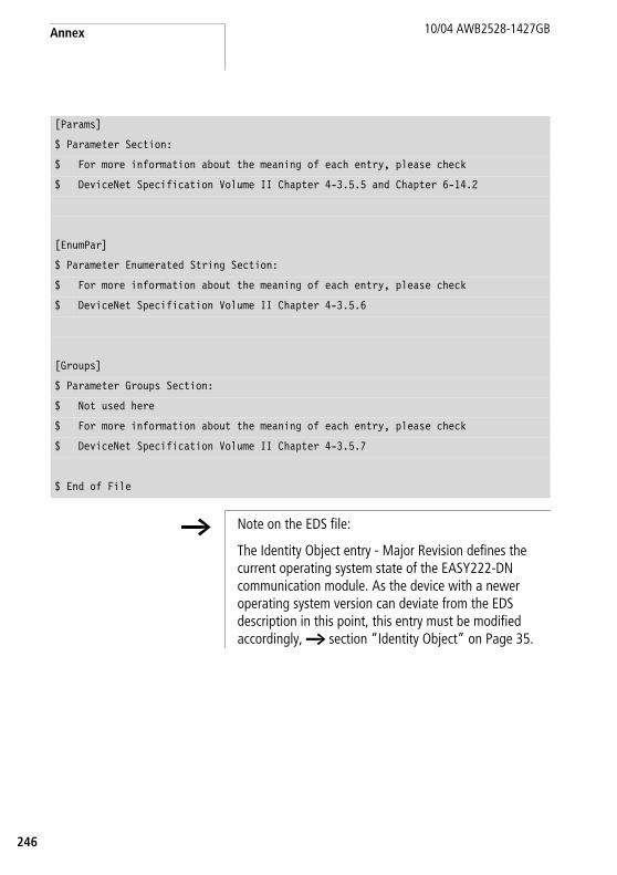
Annex
246
10/04 AWB2528-1427GB
[Params]
$ Parameter Section:
$ For more information about the meaning of each entry, please check
$ DeviceNet Specification Volume II Chapter 4-3.5.5 and Chapter 6-14.2
[EnumPar]
$ Parameter Enumerated String Section:
$ For more information about the meaning of each entry, please check
$ DeviceNet Specification Volume II Chapter 4-3.5.6
[Groups]
$ Parameter Groups Section:
$ Not used here
$ For more information about the meaning of each entry, please check
$ DeviceNet Specification Volume II Chapter 4-3.5.7
$ End of File
h Note on the EDS file:
The Identity Object entry - Major Revision defines the current operating system state of the EASY222-DN communication module. As the device with a newer operating system version can deviate from the EDS description in this point, this entry must be modified accordingly, a section “Identity Object” on Page 35.

47
10/04 AWB2528-1427GB
2
Glossary
This glossary refers to topics related to DeviceNet.
Terminating resistor Terminating resistor at the start and end of a bus cable. Prevents interference due to signal reflection and is used for the adaptation of bus cables. Bus terminating resistors must always be the last unit at the end of a bus segment.
Acknowledge Acknowledgement returned by the receiving station after having received a signal.
Address Number that identifies a memory area, systems or module within a network, for example.
Addressing Assignment or setting of an address for a module in the network, for example.
Active metallic component Conductor or conductive component that is live when in operation.
Analogue Value, such as voltage, that is infinitely variable and proportional. Analogue signals can acquire any value within specific limits.
Automation product I/O controlling device that is interconnected to a system process. PLCs represent a special group of automation products.
Baud Unit for the data transfer rate. One baud is equivalent to the transmission of one bit per second (bps).
Baud rate Unit of measure of the data transmission speed in bit/s.
Electrical equipment Comprises all equipment used for the generation, conversion, transfer, distribution and application of electrical energy, e.g. power lines, cables, machines, controllers.
Reference ground Earth potential in the area of grounding devices. May have a potential other than the zero of "earth" potential.
Reference potential Represents a reference point for measuring and/or visualising the voltage of any connected electrical circuits.
Bidirectional Operation in both directions.
Glossary
248
10/04 AWB2528-1427GB
Bit Abbreviation for the term “binary digit“. Represents the smallest information unit of a binary system. Its significance can be 1 or 0 (Yes/No decision).
Lightning protection Represents all measures for preventing system damage due to overvoltage caused by lightning strike.
Bus Bus system for data exchange, for example between the CPU, memory and I/O. A bus can consist of several parallel segments, e.g the data bus, address bus, control bus and power supply bus.
Bus line Smallest unit connected to the bus. Consists of the PLC, a module and a bus interface for the module.
Bus system All units as a whole which communicate across a bus.
Bus cycle time Time interval in which a master provides services to all slaves or nodes of a bus system, i.e. writes data to their outputs and reads inputs.
Byte A sequence of 8 bits
Code Data transfer format
COS I/O connection COS (Change Of State) I/O connections are used to set up event-controlled connections, i.e. the DeviceNet devices automatically generate messages when a status has changed.
2 byte diagnostics data of the easy control relay
Coupling module status
CPU Abbreviation for “Central Processing Unit“. Central unit for data processing. Represents the core element of a computer.
Cyclic I/O connection Message triggering is timer-controlled when operating with a cyclic I/O connection.
Device Heartbeat Message A DeviceNet unit can use the Device Heartbeat Message function to broadcast its native status at set time intervals. These messages are configured in the Identity Object.
Device Shut Down Message A device shutting down due to internal errors or states can log off at the PLC by means of the Device Shut Down Message.
Glossary
49
10/04 AWB2528-1427GB
2
Digital Represents a value that can acquire only definite states within a finite set, e.g. a voltage. Mostly defined as "0" and "1".
DIN Abbreviation for "Deutsches Institut für Normungen e. V.".
Dual Code Natural binary code. Frequently used code for absolute measurement systems.
EDS This EDS file primarily defines the Polled I/O Connection, the COS I/O Connection and the Cyclic I/O Connection of the gateway. It does not contain data or parameters (easy object) for functions of the easy basic unit. These functions are accessed by means of explicit messages.
EEPROM Abbreviation for “Electrically Erasable Programmable Read-only Memory“.
EMC Abbreviation for "Electromagnetic Compatibility". Defines the ability of electrical equipment to operate error-free and without causing a negative influence within a certain environment.
EN Abbreviation for “European Norm”.
Earth Defines in electrical engineering the conductive earth whose electrical potential is equal to zero at any point. The electrical potential in the area of earthing devices might not be equal to zero. In this case, one refers to "Reference ground".
Earthing Represents the connection of an electrically conductive component to the equipotential earth via a grounding device.
Earth electrode One or several components with direct and good contact to earth.
ESD Abbreviation for “Electrostatic Discharge”.
Fieldbus Data network on the sensor/actuator level. The fieldbus interconnects the devices at field level. Characteristic feature of the fieldbus is the highly reliable transfer of signals and real-time response.
Field power supply Power supply for the field devices and signal voltage.
Glossary
250
10/04 AWB2528-1427GB
Galvanic coupling Galvanic coupling generally develops between two circuits using a common cable. Typical interference sources are starting motors, static discharge, clocked devices and potential difference between the component enclosure and their common power supply.
GND Abbreviation for “GROUND“ (zero potential).
hexadecimal Numerical system with the base 16. The count starts at 0 to 9 a continues with the letters A, B, C, D, E and F.
I/O Abbreviation for “Input/Output“.
Impedance Alternating current-resistance of a component or of a circuit consisting of several components at a specific frequency.
Low-impedance connection Connection with low alternating-current resistance.
Inactive metallic parts Touch-protected conductive components, isolated electrically from active metallic parts by means of an insulation, but subject to fault-voltage.
Inductive coupling Inductive (magnetic) coupling develops between two current-carrying conductors. The magnetic effect generated by the currents induces an interference voltage. Typical interference sources are, for example transformers, motors, mains cables installed parallel and RF signal cables.
Capacitive coupling Capacitive (electrical) coupling develops between two conductors carrying different potentials. Typical interference sources are, for example parallel signal cables, contactor relays and static discharge.
Coding element Two-part element for the unambiguous allocation of electronic and basic module.
Command modules Command-capable modules are modules with an internal memory that are capable of executing particular commands (such as output substitute values).
CONFIGURE... Systematic arrangement of the I/O modules of a station.
Protected against short-circuit Property of electrical equipment. Short-circuit-proof equipment has the ability to withstand the thermal and dynamic loads that may occur at the location of installation on account of a short-circuit.

Glossary
51
10/04 AWB2528-1427GB
2
LSB Abbreviation for “Least Significant Bit“. Bit with the least significant value.
Chassis ground All interconnected inactive equipment parts which are not subject to hazardous fault voltage.
Earthing tape Flexible conductor, mostly braided. Interconnects inactive parts of equipment, e.g. the doors of a control panel and the switch cabinet body.
Master Station or node in a bus system that controls communication between the other stations of the bus system.
Master/Slave Mode Operating mode in which a station or node of the system acts as master that controls communication on the bus.
Mode Operating mode.
Module bus Represents the internal bus of an XI/ON station. Used by the XI/ON modules for communication with the gateway. Independent of the fieldbus.
MSB Abbreviation for “Most Significant Bit“. Bit with the most significant value.
Multimaster Mode Operating mode in which all stations or nodes of a system have equal rights for communicating on the bus.
NAMUR Abbreviation for "Normen-Arbeitsgemeinschaft für Mess- und Regeltechnik". NAMUR proximity switches represent a special category of 2-wire proximity switches. They are highly resistant to interference and reliable due to their special construction, e.g. low internal resistance, few components and short design.
Offline Connection Set The Offline Connection Set allows communication with a device that is in communication error state but not in bus-off state due to an ambiguous address. It is usually no longer possible to address this device on the network, and it must be initialised manually by switching it off and on. The Offline Connection Set can be used in this situation to address such a device on the network.
Overhead System management time. Required once for each data transfer cycle.

Glossary
252
10/04 AWB2528-1427GB
Parameter assignment Definition of parameters for individual bus stations or their modules in the configuration software of the DeviceNet master.
Polled I/O connection A polled I/O connection is used to establish a conventional master/slave relation between a PLC and a DeviceNet device, and represents a PtP connection between two stations on the fieldbus. The master (client) transmits a polling request to the slave (server), and this answers with a polling response.
• 3 bytes of output data S1 to S8easy/MFD output range, RUN/STOP (inputs at the DeviceNet master)
• 3 bytes of input dataR1 to R16easy/MFD input range, RUN/STOP (outputs of the DeviceNet master)
Equipotential bonding Adaptation of the electrical level of the body of electrical equipment and auxiliary conductive bodies by means of an electrical connection.
Potential-free Galvanic isolation between the reference potentials of the control and load circuit of I/O modules.
Common potential Electrical interconnection of the reference potentials of the control and load circuit of I/O modules.
Response time In a bus system this represents the time interval between the transmission of a read request and receiving the answer. Within an input module, it represents the time interval between the signal change at an input and its output to the bus system.
Repeater Amplifier for signals transferred across a bus.
Screen Term that describes the conductive covering of cables, cubicles and cabinets.
Shielding Refers to all measures and equipment used to connect system parts to the screen.

Glossary
53
10/04 AWB2528-1427GB
2
Protective conductor Conductor required for human body protection against hazardous currents. Abbreviation: PE (“Protective Earth“).
Serial Describes an information transfer technique. Data are transferred in a bit-stream across the cables.
Slave Station or node in a bus system that is subordinate to the master.
PLC Abbreviation for Programmable Logic Controller.
Station Function unit or module, consisting of several elements.
Noise emission (EMC) Testing procedure to EN 61000-6-4
Noise immunity (EMC) Testing procedure to EN 61000-6-2
Radiation coupling Radiated coupling occurs when an electromagnetic wave makes contact with a conductor structure. The impact of the wave induces currents and voltages. Typical interference sources are, for example ignition circuits (spark plugs, commutators of electrical motors) and transmitters (e.g. radio-operated devices), which are operated near the corresponding conductor structure.
Topology Geometrical network structure, or circuit arrangement.
UART Abbreviation for “Universal Asynchronous Receiver/Transmitter“. A "UART" represents a logical circuit used to convert an asynchronous serial data stream into a parallel bit stream and vice versa.
UCMM The DeviceNet gateway provides an option of configuring dynamic connection objects via the UCMM port (Unconnected Message Manager Port).
Unidirectional Operating in one direction.

254
10/04 AWB2528-1427GB

10/04 AWB2528-1427GB
55
2Index
7-day time switcheasy700 .............................................125, 141easy800/MFD .............................................208
A Address range .....................................................24ALT button, read state .........................................64Analog comparators
easy600 (write reference values) ..................73easy700 .....................................................127easy700, read status ..................................106easy800/MFD .............................................176
Analog outputeasy800/MFD, read status ..........................167
Application Objects .............................................34Application-specific objects .................................34Arithmetic function block
easy800/MFD .............................................178Assembly Objects ................................................34Auto baud recognition .........................................22
B Bit array ............................................................103Block Compare
easy800/MFD .............................................180Block Transfer
easy800/MFD .............................................182Boolean operation
easy800/MFD .............................................184Bus cable lengths ................................................22Button inputs P1 to P4
easy600 .......................................................62

Index 10/04 AWB2528-1427GB
256
C Communication profile ........................................14Comparators
easy800/MFD .............................................194Connection ID .....................................................44Connection objects ..............................................33Control commands
easy600 .......................................................55easy700 .......................................................99easy800 .....................................................145
COS I/O connection ...........................................248Counter relays
easy600 (read reference value) .....................80easy600, read actual value ...........................76easy600, write setpoint ................................78easy700 .....................................................130
Counterseasy700, read status ..................................107easy800/MFD .............................................186
Cycle time ...........................................................29Cyclic data exchange ...........................................47Cyclic I/O connection .........................................248
D Data blockeasy800/MFD .............................................199
Data exchange, PDO ...........................................47Data transfer rates ..............................................22DEL button, read state ........................................64Delay time, random value ....................................84Device address ....................................................43Device Shut Down Message ..............................248DeviceNet
Connecting ..................................................19Object ..........................................................33Pin assignment .............................................19
DeviceNet terminal assignment ...........................19Diagnostics, local
easy800/MFD (image data) ........................157Diagnostics, remote station
easyMFD (image data) ...............................157

Index
57
10/04 AWB2528-1427GB
2
Digital inputseasy600, read status ....................................62easy700, read status ..................................109easy800/MFD, read status ..........................159
Digital outputseasy600, read status ....................................69easy700, read status ..................................119
Dimensions ........................................................242Direct data exchange ...........................................47
E easy Object ....................................................34, 38easy800/MFD (read) ..........................................149EDS file ................................................................29Error codes, via EASY-LINK
easy700 .....................................................144easy800/MFD .............................................234
ESC button, read state .........................................64Explicit Messages ................................................42
F Frequency counterseasy800/MFD .............................................188
Function blocks, overvieweasy600 .......................................................72easy700 .....................................................126easy800/MFD .............................................175
H Hardware requirements .......................................15Heartbeat Message ...........................................248High-speed counter
easy800/MFD .............................................190Hour
....................................................................93easy600 .......................................................58Real-time clock .............................................97

Index 10/04 AWB2528-1427GB
258
I Identity Object .....................................................33Image data
General information .....................................61Overview easy700 ......................................105Overview of easy800/MFD .........................154Overview, easy600 .......................................61
Incremental encoder counterseasy800/MFD .............................................192
Initial power on ...................................................23Input data, definition ..........................................48Inputs of EASY-LINK
easy700, read status ..................................120easy800/MFD, read status ..........................170
Inputs, network stationseasy800/MFD, read status ..........................161
Invalid operating mode .............................144, 234Invalid telegram ........................................144, 234
L LED status displays ......................................27, 237Local analog output
easy800/MFD, read status ..........................167Local inputs
easy700, read status ..................................109easy800/MFD, read status ..........................159
Local outputseasy700, read status ..................................119
M MAC ID .........................................................43, 44Marker relays
easy600, read status ....................................69Markers
easy600, read status ....................................69easy700, read ............................................114easy700, write ...........................................112easy800/MFD, read status ..........................162
Master reseteasy700 .....................................................124easy800/MFD .............................................216
Index
59
10/04 AWB2528-1427GB
2
Message group ....................................................44Message ID .........................................................44Message Router Object ........................................33Minute
....................................................................93easy600 .......................................................59Real-time clock .............................................97
Module status LED ......................................27, 237MS LED .......................................................27, 237
N Network station, read the input states ...............161Network status LED .....................................28, 237Node address ......................................................43NS LED ........................................................28, 237Numerical converter
easy800/MFD .............................................218
O OFF time ....................................................................93Real-time clock .............................................97
Offline Connection Set .......................................251OK button, read state ..........................................64ON time
....................................................................93Real-time clock .............................................97
ON/OFF times ....................................................................93Real-time clock .............................................97
Operating buttonseasy600, read status ....................................62
Operating hours countereasy700 .....................................................133easy800/MFD .............................................220
Operating mode, invalid ............................144, 234Operating system requirements ...........................15Output data, definition ........................................48
Index 10/04 AWB2528-1427GB
260
Outputs of EASY-LINKeasy700, read status ..................................120easy800/MFD, read status ..........................170
Outputs, local and network stationseasy800/MFD, read status ..........................168
P P buttonseasy600, read status ....................................62easy700, read status ..................................117easy800, read status ..................................165
PDO ....................................................................47PID controllers
easy800/MFD .............................................201Polled I/O connection ........................................252Potential isolation ...............................................21Power supply ......................................................18Pulse width modulation
easy800/MFD .............................................224
R Read/write dateeasy600 .......................................................57easy700 .............................................101, 148
Read/write timeeasy600 .......................................................57easy700 .............................................101, 148
Reading analog inputseasy600, read status ....................................65
Reading analogue inputseasy700, read status ..................................110easy800/MFD, read status ..........................155
Reading outputs S1 to S8 ....................................50Reading the status of
Reading outputs S1 to S8 .............................50Reading the mode ........................................49Set operating mode ......................................51Setting inputs R1 to R8 ................................54
Index
61
10/04 AWB2528-1427GB
2
Receive data, network stationseasy800/MFD .............................................206easy800/MFD, read status ..........................172
Receive network dataeasy800/MFD .............................................206
Resetting, easy/MFD inputs/outputs ....................51Response time of the basic unit ...........................29
S SDOControl Commands for easy600 ...................55Control commands for easy700 ....................99Control commands for easy800 ..................145
Send data, network stationseasy800/MFD .............................................222easy800/MFD, read status ..........................172
Send network dataeasy800/MFD .............................................222
Set cycle timeeasy800/MFD .............................................227
Set operating mode .............................................51Set/reset inputs R1 to R8 .....................................54Setting the address
with EASY-SOFT ...........................................26Setting the slave address .....................................24Setting, easy/MFD inputs/outputs ........................51Signal smoothing filter
easy800/MFD .............................................204Structure of the unit ............................................13Summer time
easy600 .......................................................57easy700 .....................................................102easy800/MFD .............................................149
Switching rule ...................................................103Switching timers
easy600 (read actual values) ........................90easy600, write setpoint ................................94
Synchronize clockeasy800/MFD .............................................226
System overview ..................................................12

Index 10/04 AWB2528-1427GB
262
T Telegram, invalid .......................................144, 234Terminating resistors ...........................................20Text display
easy600, read status ....................................69Text function block
easy700, read status ..................................108Text marker .........................................................71Text output function block
easy800/MFD .............................................196Threshold value comparator
easy700, read status ..................................106Threshold value switch
easy700 .....................................................127Timing relays
easy600 (write parameters) ..........................86easy600, read actual value ...........................82easy700 .....................................................135easy700, read status ..................................122easy800/MFD .............................................229
Transmit data, network stationseasy800/MFD, read status ..........................172
U UCMM ..............................................................253

Index
63
10/04 AWB2528-1427GB
2
V Value limitationeasy800/MFD .............................................232
Value scalingeasy800/MFD .............................................214
Version history, easy800 ....................................148
W Weekdayeasy600 .......................................................58
Winter timeeasy600 .......................................................57easy700 .....................................................103easy800/MFD .............................................149
Writing the comparison value, (analog value comparator) ........................................................74
Y Year time switcheasy700 .....................................................138easy700, read status ..................................123easy800/MFD .............................................211