rcm2 limited - safety requirements, goals & hazard … · iscade pro white paper d1 1....
TRANSCRIPT

Weston Villa, 37 Wolsey Road, Esher, Surrey KT10 8NT, UK
rcm2 limitedT: +44 1372 468312; F: +44 871 9898834 ; M: +44 7810 635156
e: [email protected]; http://www.rcm2.co.uk
Specification for
ISCaDE™Pro
© rcm2 limited 2006
This document is the property of rcm2 limited and the information contained herein is confidential. The document, either in whole or part, must not be reproduced, or disclosed to others, or used for purposes other than that for which it is supplied, without rcm2 limited’s prior written permission; or, if any part hereof is furnished by virtue of a contract with a third party, as expressly authorised under that contract. Summary Release notes of ISCaDE™ Pro Date 30 March 2006

1. ISCADE™ PRO ARCHITECTURE..........................................................................................................1 1.1. LAYERED ARCHITECTURE .....................................................................................................................1
A) CONFIGURATION REPOSITORY................................................................................................................................. 2 B) DATA LAYER .......................................................................................................................................................... 3 C) USER INTERFACE .................................................................................................................................................... 3
1.2. ARCHITECTURE FOR CONCURRENT DATA MANIPULATION ...................................................................3 1.3. IMPLEMENTATION .................................................................................................................................4 1.4. LIMITATIONS .........................................................................................................................................4
2. INHERENT FEATURES FROM ISCADE™ 1.2 .....................................................................................5 2.1. MULTI LEVEL MULTI USER ACCESS .....................................................................................................5 2.2. SAFETY CASE MODEL ...........................................................................................................................5
A) GSN – GOAL STRUCTURING NOTATION .................................................................................................................. 5 B) DRAW A SAFETY CASE DIAGRAM.......................................................................................................................... 11 C) DIAGRAM CONFIGURATION................................................................................................................................... 11 D) SAFETY CASE MODEL METRICS (GSN)................................................................................................................. 12
3. WHAT’S NEW IN ISCADE™ PRO ........................................................................................................14 3.1. CONFIGURABLE HAZARD LOG.............................................................................................................14 3.2. MULTI MODULE HAZARD LOG............................................................................................................14 3.3. ENHANCED GRAPHICAL USER INTERFACE...........................................................................................14 3.4. NEW LINK ARCHITECTURE..................................................................................................................14 3.5. ENHANCED TRACEABILITY..................................................................................................................14 3.6. CONCURRENT DATA MANIPULATION..................................................................................................14 3.7. INTERACTIVE COMBINED IMPACT DATA .............................................................................................15
A) DOUBLE CLICK FUNCTIONALITY ........................................................................................................................... 15 3.8. ONE STEP EASY IMPORT FROM MICROSOFT EXCEL.............................................................................15 3.9. AUTOMATED LINK MANAGEMENT ......................................................................................................15 3.10. AUTOMATED MODE MANAGEMENT ....................................................................................................15 3.11. INDEPENDENT XML BASED CONFIGURATION REPOSITORY .................................................................16 3.12. USER DESIRED MODE..........................................................................................................................16 3.13. ENHANCED SAFETY RISK MATRIX ......................................................................................................16 3.14. TECHNICAL SUPPORT FOR DATA IMPORT ............................................................................................17
4. USAGE GUIDE FOR ISCADE™ PRO ...................................................................................................18 4.1. PROJECT CREATION.............................................................................................................................18 4.2. SECTIONING ........................................................................................................................................18 4.3. MODULE MODES .................................................................................................................................18 4.4. SETTING UP FOR SHARING...................................................................................................................18
5. USER CONSIDERATIONS......................................................................................................................20 5.1. SIMULTANEOUS EDITING.....................................................................................................................20 5.2. THE FORMS STATES ............................................................................................................................20 5.2.1. READ ONLY OR NAVIGATIONAL STATE...............................................................................................20 5.2.2. EDIT/INSERT READY STATE ................................................................................................................20 5.2.3. EDIT STATE .........................................................................................................................................20 5.2.4. INSERT STATE .....................................................................................................................................20
6. DEVELOPMENT TEAM BACKGROUND ...........................................................................................21 7. KNOWN PROBLEMS AND LIMITATIONS ........................................................................................22
7.1. PROBLEM 1..........................................................................................................................................22 8. GLOSSARY................................................................................................................................................23 9. ACRONYMS AND ABBREVIATIONS ..................................................................................................24 10. LIST OF FIGURES...............................................................................................................................25

ISCaDE Pro White Paper d1
1. ISCaDE™ Pro Architecture ISCaDE™ Pro is a comprehensive software solution to facilitate the Safety Staff to identify, assess and analyse hazards and accidents associated with them through the whole lifecycle of the project. ISCaDE™ is a safety case development environment built on top of DOORS® (Dynamic Object Oriented Requirement Systems) database. ISCaDE™ Pro is developed to address the more dynamic requirements of the industry regarding Hazard Log and Safety Case. ISCaDE™ Pro is an enhancement of ISCaDE™ version 1.2. Its architecture is purely different form the previous version. ISCaDE™ Pro is completely different form ISCaDE™ 1.2 as it provides many new features including ‘Concurrent Data Manipulation’ on the same project, Interactive Combined Impact View, Automatic Module Mode and Link Management etc. [NB: I is important to note that previous version 1.2 also allows this facility on multiple projects and concurrent read-only viewing of forms and risk matrix by multiple users.] The following paragraphs summarise the architecture, implementation and limitations of ISCaDE™ Pro.
t
1.1. Layered Architecture ISCaDE™ Pro has a very flexible architecture as far as different safety standards are concerned. With the isolation of configuration data repository from the main application, it’s easy to update and use any new configuration data repository made for a different standard (e.g. Defence, Railwise, ACA etc). Now you can easily mould ISCaDE™ Pro for your own needs and requirements. In this regard technical support is available to help you.
DOORS Database User
Interface Configuration
Repository
Figure 1: Layered Architecture of ISCaDE™ Pro
Configuration Repository (XML Configuration Files)
ISCaDE™ Pro Project Data (Actual Hazard Log)
User Interface (ISCaDE™ Pro Forms)
SCaDE™ Pro Project
ISCaDE Pro Forms
© rcm2 limited Page 1 of 25

ISCaDE Pro White Paper d1
ISCaDE™ Pro is mainly divided into three layers. This makes it more flexible, adoptable and easy to use product in the domain of safety & reliability. The layers are: • Configuration Repository • Data Layer • User Interface
Figure 2: Layered Approach Benefits
Functionality of these layers is discussed below.
a) Configuration Repository ISCaDE™ Pro places the configuration for a project at separate layer called Configuration Layer. Configuration of project is XML (Extensive Markup Language) based. Two XML files are required to configure a project. One file contains the list of attributes that one project will have and the other contains, risk classification matrix for that project. This feature makes ISCaDE™ Pro more dynamic and customisable. The user can have as many configuration files as he/she wants and then can use it for creating and managing its project. Multiple projects can share the same configuration files. The file containing risk classification, stores the risk matrix as per user requirement in compliance with the standard that user has chosen.
ISCaDE™ Pro(Integrated Safety Case
Development Environment)
GUI Set 1
GUI Set 2
ConfigurationFiles Set 1
Configuration Files Set 2
GUI Set 1Configuration
Files Set 3
♦ Configuration Files Set includes the project configuration repository and safety risk matrix configuration repository
♦ GUI Set includes all ISCaDE™ Pro module forms and the safety risk matrix
© rcm2 limited Page 2 of 25

ISCaDE Pro White Paper d1
If the configuration file is corrupted the user may not be able to view Safety Risk Matrix (also know as Risk Classification Matrix) and other GUI components.
b) Data Layer This is the layer where project resides. This lies inside the DOOR® environment. This is configured on the basis of configuration repository. ISCaDE™ Pro reads the data repository and creates the project for the user. (Please see ISCaDE™ Pro User Manual to know more about automatic/custom project creation). When the project is created the user can access this layer and can enter/edit data using standard DOORS® functionality. This layers acts as a foundation or base for the User Interface.
c) User Interface Major differences have been made in the User Interface. Layout of almost all the module forms is same. The standard features along with the new features (that are based the customer feedback/suggestions) are incorporated. User Interface have new feature called Link Management (see section 3.9). This allows the user to create/modify links using forms that provided with ISCaDE™ Pro.
1.2. Architecture for Concurrent Data Manipulation As stated above ‘Concurrent Data Manipulation’ is achieved using the ‘Shareable Edit’ functionality of DOORS. The architecture is very simple as described below: The module to be manipulated concurrently must be opened in ‘Shareable Edit’ mode by the user. Besides opening in ‘Shareable Edit’ mode, the module should be Setup for sharing. ‘Setup for Sharing’ means that there should be ‘Shareable Sections’ defined for the module. This can be done by going to Tools Setup for sharing… and selecting the desired ‘level’ from the drop down list on the form. This creates the sections equal to the no. of objects present in the selected level. This sectioning can only be defined in ‘Exclusive Edit’ mode. For the purpose of current ISCaDE™ Pro functionality it is required to create the sections at level 1 (the default choice). Once ‘Shareable Sections’ are defined for a certain level of the module, then all the objects with that certain level are ready for ‘Concurrent Data Manipulation’. But this ‘Concurrent Data Manipulation’ requires the lock of a particular object while changing the data. When a user wants to edit an object for which sectioning has already been done, the user has to obtain lock of that object. This would make that object ‘Read-Only’ for all other users of the database and only the user with object lock is allowed to edit that object. During this period, no other user can obtain lock of that object for editing. After changing the object data, the user should release the lock of the object so as to make it editable for other users as well. So we can say that at module level, data can be manipulated concurrently, but at section or object level only one user at a time can change the data.
© rcm2 limited Page 3 of 25

ISCaDE Pro White Paper d1
1.3. Implementation The above architecture is followed in ISCaDE™ Pro as follows: When any ISCaDE™ Pro form is opened for a particular module, it tries to switch the module mode to user desired mode. If the module is opened in user desired mode, then it provides all the features and functionalities available in that particular mode. If the module is opened in ‘Read Only’ mode, it only allows navigation facility i.e. both ‘New’ and ‘Edit’ button would be disabled in this mode. If the module is opened in ‘Shareable Edit’ mode then it allows concurrent data manipulation. It provides navigation as well as editing facility to the user. For editing object data each form is provided with an ‘Edit’ button. The ‘Edit’ button event first tries to obtain the lock for current object. If it fails to lock the object it gives respective errors i.e. (1. Sections not defined 2. Object already locked). Upon successful locking all the fields on the form become enabled/editable and the user is allowed to change the data. After changing the data when user clicks the ‘Save’ button, then the change is saved and the lock for that object is released, to make it editable for other users as well. For inserting new object each form is provided with a ‘New’ button. On click of New button form tries to re-open the module in Exclusive Edit Mode if not already opened in Exclusive Edit Mode. If it succeeds then presents user the controls to enter the data. When user finishes with new record and presses the Save button, ISCaDE™ inserts the new object in the module and asks the user as whether the user wants to insert more records. On the choice of user the form switches in previous state or provides the user an opportunity to insert another record. The “Interactive Combined Impact Data” is also designed with the same architecture in view. Each mini form on the ‘Accident Module’ follows the same ‘Locking’ mechanism to change the linked objects (HAZ, CAU, and SAF). Whenever ‘Edit Link’ button is pressed for any HAZ, CAU or SAF object, the respective mini form first tries to obtain the lock for that particular HAZ, CAU or SAF object respectively. If lock is successfully obtained, only then the user is allowed to change the linked object’s data. In other case appropriate warning/error message is displayed and the mini form is opened in “Read Only” mode.
1.4. Limitations User is not allowed to change the data for an object for which sectioning is not defined using ‘Edit’ button on the form, as an object with no section cannot be locked. Insertion of new objects can only be done in ‘Exclusive Edit’ mode. Moreover sectioning process also requires the module to be opened in ‘Exclusive Edit’ mode.
© rcm2 limited Page 4 of 25

ISCaDE Pro White Paper d1
2. Inherent Features from ISCaDE™ 1.2
2.1. Multi Level Multi User Access As ISCaDE™ Pro uses Telelogic DOORS platform, it has inherited network support feature. ISCaDE™ Pro exploits it by setting multi-level access for multiple users.
2.2. Safety Case Model With the initialization of a project, ISCaDE™ Pro automatically initializes a Safety Case Module create Safety Case Model. This feature is integrated in ISCaDE™ Pro from ISCaDE™ 1.2, which allows analysis of the safety cases. Currently ISCaDE™ Pro supports one and the most widely used Safety Case Model i.e. the GSN model – Goal Structuring Notation. A more detailed explanation on GSN is given in the following section.
a) GSN – Goal Structuring Notation As described above, the initialization process of ISCaDE™ Pro automatically initializes a GSN Safety Case Module by default. A new object at level 1, acting as the goal of GSN model is also added by ISCaDE™ Pro. All other objects must be created below the goal object, i.e. should be children of it. Add objects below an existing object by selecting the existing object then selecting the ‘New object below’ button or Object Below from the Insert menu. Type of Objects/Attributes Goals
A goal is a requirement, target or constraint to be met by the system. The term goal hierarchy refers to the collection of goals produced by the hierarchical decomposition of goals into sub-goals.
Models
A goal is couched in terms of some model of the system, or its environment. A goal may be expressed over a number of models. This model may take a number of forms – e.g. a plant schematic, a process description or an architectural model.
Strategies
© rcm2 limited Page 5 of 25

ISCaDE Pro White Paper d1
A goal (or set of goals) can be solved by a strategy, which breaks down a goal into a number of sub-goals. A strategy can be regarded as a rule to be invoked in the solution of goals. Justifications
Strategies often need some justification for their use. A justification calls upon a reason or evidence that supports a strategy.
Criteria
Criteria are used to decide whether a goal has been satisfactory solved. They provide measures and procedures for assessing goal satisfaction.
Constraints A constraint is used to restrict the way in which goals can be solved, e.g. a common safety requirement is ‘no single point of failure shall lead to a hazard’.
Solutions Goals may be solved directly by solutions, rather that by decomposition into sub-goals. Solutions will be individual pieces of analysis, evidence, results of audit reports, or references to design material.
Contexts
Goals often need some justification for their use.
© rcm2 limited Page 6 of 25

ISCaDE Pro White Paper d1
Assumptions Include assumptions made.
Link type
Shows relationships between objects (Goals, Strategies and Solutions) Shows relationships between objects and attributes (Contexts)
Assigning Context types to Objects Goals and strategies can be assigned different contexts by using the ‘Context Type’ column in the ‘GSN’ view. Double-clicking on this column will display the six context types mentioned above. Selecting one or more of these values will activate appropriate columns to enter relevant text for each type. Please note that only the first two selected contexts will be displayed in the safety case model. Multiple-parents in GSN For the most part in GSN, child objects are descendant of only one parent. For instance, a high level goal may have several sub-goals, but each of these sub-goals tends to solve only one goal. However, it is entirely possible that a sub goal of a high level goal is relevant to another independent high level goal. The nature of DOORS database does not allow for an object to have more than one parent without duplication. ISCaDE® represents Multiple Parentage of objects using links. When creating GSN diagrams with Multiple Parents in ISCaDE® the child needs only to be created once. It is important that the child is created under its first parent, hierarchically. To make an object an additional parent of a child you can either:
1. Select the Object (new parents) 2. Click and hold the Left Mouse Button (LMB) on this object 3. Whilst holding LMB drag to the child object you wish to make your current
object the parent of 4. Release LMB and select Make Link from Start
Or: 1. Right click on the object 2. Select Link > Start Link 3. Select the child object 4. Right click and select Make Link from Start
5. The link will be designated by the presence of a small purple triangle on the parent object and a small yellow triangle on the child object at the edge of their respective heading columns.
If you want to cancel the creation of the link when using the drag method above
1. Choose Cancel instead of Make Link from Start at step c). The object you wanted to make your parent will now be coloured pink.
2. To remove this, click the Right Mouse Button (RMB) and select Link > Clear Start.
© rcm2 limited Page 7 of 25

ISCaDE Pro White Paper d1
If you want to cancel the creation of the link when using the select method above
1. If Start Link has not been selected yet then simply click LMB away from pop-up menu. Otherwise right click and select Link > Clear Start.
Remove Multiple Parent Relationships To remove multiple parent relationships delete their links as follows:
1. Select the parent or child object whose link you want to delete 2. Select the Edit Links from Link in the top menu
You see the object properties sheet, with the Links tab selected 3. You see a list of all the links in and out of the object.
For each link: • The In/Out column tells you the direction of the link • The Module column tells you which module contains the object at the
other end of the link • The Object Heading/Text column shows the first bit of the Object Text
for the object at the other end of the link • The ID column shows the object identifier of the object at the other end
of the link 4. To delete a link, select it, then click Delete 5. Save the module.
Please note that, to avoid complexity and overlapping in diagrams, links between objects that are more than one level apart will be replaced by red text below the objects indicating where the link is to (in case of parent) and where the link is from (in case of child). Figure 3 gives a simple example of multiple-parenting. Links between object 1.1 and 1.2.1 that are only one level apart are displayed by an arrow. However, links between object 1.2 and 1.1.1.1 are displayed by text instead.
© rcm2 limited Page 8 of 25

ISCaDE Pro White Paper d1
Figure 3: Multiple parenting in ISCaDE
Relationship rules
1. Goal Structuring Notation can have only one top-level object. 2. Goals can be followed by sub-goals, strategies or solutions only. 3. Solutions, Assumptions, Contexts, Modules, Justifications, Constraints and
Criteria can have incoming links only.
© rcm2 limited Page 9 of 25

ISCaDE Pro White Paper d1
Figure 4: A Typical GSN module in ISCaDE (for Railwise case study)
A typical GSN Safety Case model should look similar to Figure 4. The corresponding diagram will look similar to Figure 5. To draw the diagram see <<section>> ‘Draw a Safety Case Diagram’.
© rcm2 limited Page 10 of 25

ISCaDE Pro White Paper d1
Figure 5: GSN diagram for Railwise
Pleas note that the Safety Case Diagram aims to show clearly the model created. When the Safety Cases become too complex the diagram may become cluttered. The diagram should then be configured in order to view the information more clearly. Diagrams can also be created from objects other than the main goal allowing all the information to be displayed over a number of diagrams. Select the object you wish to draw the diagram of from the module and run the Draw a Safety Case Diagram tool. This will display that object with the hierarchy beneath it.
b) Draw a Safety Case Diagram For the graphical representation of the safety case model select Safety Case > Draw a Safety Case Diagram from the ISCaDE menu of the safety case model module. The diagram displayed will be dependant upon the model used. The following figures show what a populated safety case model module looks like, together with its corresponding diagram, for the three possible models. The diagrams can be printed, exported as a Windows metafile or configured using the buttons in the bottom right corner of the windows.
c) Diagram Configuration Configuration is tailored to the model used. Figure 6 shows the configuration box for GSN. The level of the hierarchy to be displayed can be altered; the labels against each shape can be shown or hidden; a caption can be entered which will entitle the diagram;
© rcm2 limited Page 11 of 25

ISCaDE Pro White Paper d1
object headings and identifiers can be displayed or hidden and the shape size can be altered. Changes in these settings will take affect when the Apply button is clicked. To apply the default settings, click Default.
Figure 6: Configuration box for GSN diagram
d) Safety Case Model Metrics (GSN) The Display Metrics on a Safety Case Model tool in GSN provides indication of incomplete goals and arguments as well as a useful summary for number of Goals, Strategies, Solutions and Contexts. The GSN Metrics can be viewed by selecting it from ISCaDE > Safety Case.Figure 7 shows the metrics for the GSN safety case for our Railwise example.
© rcm2 limited Page 12 of 25

ISCaDE Pro White Paper d1
Figure 7: Metrics for GSN safety case for Railwise
© rcm2 limited Page 13 of 25

ISCaDE Pro White Paper d1
3. What’s New in ISCaDE™ Pro ISCaDE™ Pro is completely different form ISCaDE™ 1.2 as not only the internal architecture is different but it provides many new features than the old version. Following paragraphs summarize the new features of ISCaDE™ Pro.
3.1. Configurable Hazard Log ISCaDE™ Pro is totally based on the configuration saved in a data repository. Its automatic initialisation process requires a single click and creates nine different modules along with customised views, attributes and types. For each project you can have separate configuration that will be used for that project. However, one configuration can be shared by several projects.
3.2. Multi Module Hazard Log Hazard Log is split into five different modules; namely, Hazard Module, Accident Module, Safety Functions Module, References Module and Users Module. With this isolation, the safety engineer can better manage the Hazard Logs along with having full control on traceability. The ISCaDE™ Pro initialises all these modules along with their respective views, attributes and types, according to the configuration saved in the data repository.
3.3. Enhanced Graphical User Interface The above mentioned modules from the hazard log are provided with their respective forms. The GUI of ISCaDE™ Pro makes it easy to navigate between the objects, to view object records, to update the attribute values and to view the links between the module objects. The GUI enhanced features have greatly improved the efficiency and usability of ISCaDE™ Pro.
3.4. New Link Architecture ISCaDE™ Pro has a complete new architecture of links. All the links are initiated from Hazard Module, with the Hazard Module acting as the “Source” for all “Safety Links”. The only link module used to store the links is “module_links”.
3.5. Enhanced Traceability Hazards, Accidents and other objects of different modules can be linked. Combined Impact View in the accident module shows all of these and hence exploits the DOORS traceability feature. In addition to this module forms also allow the user to view the linked records form other modules. Moreover, the Accident Module Form also allows user to modify the linked objects of Hazard, Safety Functions or References Module.
3.6. Concurrent Data Manipulation ISCaDE™ Pro allows the users on the network to work seamlessly on the same project. It automatically manages the access and privileges for the user and multiple users can work at the same time.
© rcm2 limited Page 14 of 25
ISCaDE Pro White Paper d1
With this functionality, now two or more ISCaDE™ Pro users can manipulate the data of a single module concurrently. All the Setup required by DOORS for module sharing is automatically done by ISCaDE™ Pro. Now by using ISCaDE™ Pro forms users can seamlessly change the data of their respective fields/disciplines in a module without disturbing other users working on the same module with a different discipline.
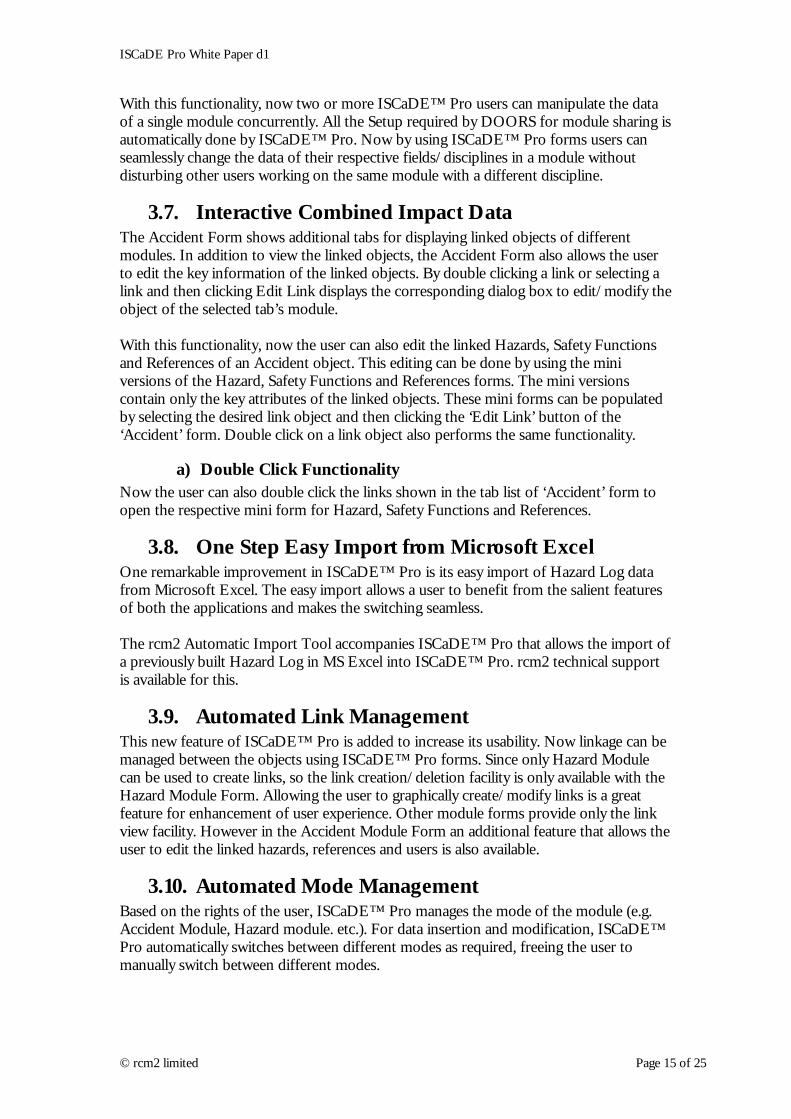
3.7. Interactive Combined Impact Data The Accident Form shows additional tabs for displaying linked objects of different modules. In addition to view the linked objects, the Accident Form also allows the user to edit the key information of the linked objects. By double clicking a link or selecting a link and then clicking Edit Link displays the corresponding dialog box to edit/modify the object of the selected tab’s module. With this functionality, now the user can also edit the linked Hazards, Safety Functions and References of an Accident object. This editing can be done by using the mini versions of the Hazard, Safety Functions and References forms. The mini versions contain only the key attributes of the linked objects. These mini forms can be populated by selecting the desired link object and then clicking the ‘Edit Link’ button of the ‘Accident’ form. Double click on a link object also performs the same functionality.
a) Double Click Functionality Now the user can also double click the links shown in the tab list of ‘Accident’ form to open the respective mini form for Hazard, Safety Functions and References.
3.8. One Step Easy Import from Microsoft Excel One remarkable improvement in ISCaDE™ Pro is its easy import of Hazard Log data from Microsoft Excel. The easy import allows a user to benefit from the salient features of both the applications and makes the switching seamless. The rcm2 Automatic Import Tool accompanies ISCaDE™ Pro that allows the import of a previously built Hazard Log in MS Excel into ISCaDE™ Pro. rcm2 technical support is available for this.
3.9. Automated Link Management This new feature of ISCaDE™ Pro is added to increase its usability. Now linkage can be managed between the objects using ISCaDE™ Pro forms. Since only Hazard Module can be used to create links, so the link creation/deletion facility is only available with the Hazard Module Form. Allowing the user to graphically create/modify links is a great feature for enhancement of user experience. Other module forms provide only the link view facility. However in the Accident Module Form an additional feature that allows the user to edit the linked hazards, references and users is also available.
3.10. Automated Mode Management Based on the rights of the user, ISCaDE™ Pro manages the mode of the module (e.g. Accident Module, Hazard module. etc.). For data insertion and modification, ISCaDE™ Pro automatically switches between different modes as required, freeing the user to manually switch between different modes.
© rcm2 limited Page 15 of 25

ISCaDE Pro White Paper d1
3.11. Independent Xml Based Configuration Repository Unlike the previous version, the configuration layer is separated from the project (or data) layer. XML (Extensive Markup Language) technology is used to meet the dynamic needs of the industry. This concept has added the functionality of having separate, even though shareable, configuration repositories for different projects. This helps in addressing specific needs of different industrial sectors.
3.12. User Desired Mode ISCaDE™ Pro is provided with an option to switch to a module mode that is specified by the user. So that whenever user opens any of the ISCaDE™ Pro Forms, its desired mode is automatically adapted. In a network based environment, each individual user can set its own user desired mode according to the requirements.
3.13. Enhanced Safety Risk Matrix The Safety Risk Matrix (SRM) is also enhanced and made dynamic to be able to display SRM for different safety standards. As the isolation of main configuration repository, the SRM configuration is also isolated from the main application. Now different configurations for SRM display different Risk Matrices from one ISCaDE™ Pro (see examples below).
Figure 8: Safety Risk Matrix for ACA
Figure 9: Safety Risk Matrix for Defence
© rcm2 limited Page 16 of 25
ISCaDE Pro White Paper d1
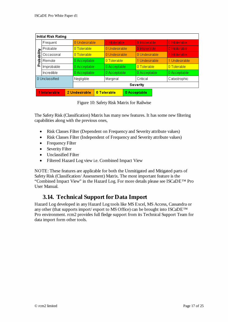
Figure 10: Safety Risk Matrix for Railwise
The Safety Risk (Classification) Matrix has many new features. It has some new filtering capabilities along with the previous ones,
• Risk Classes Filter (Dependent on Frequency and Severity attribute values) • Risk Classes Filter (Independent of Frequency and Severity attribute values) • Frequency Filter • Severity Filter • Unclassified Filter • Filtered Hazard Log view i.e. Combined Impact View
NOTE: These features are applicable for both the Unmitigated and Mitigated parts of Safety Risk (Classification/Assessment) Matrix. The most important feature is the “Combined Impact View” in the Hazard Log. For more details please see ISCaDE™ Pro User Manual.
3.14. Technical Support for Data Import Hazard Log developed in any Hazard Log tools like MS Excel, MS Access, Cassandra or any other (that supports import/export to MS Office) can be brought into ISCaDE™ Pro environment. rcm2 provides full fledge support from its Technical Support Team for data import form other tools.
© rcm2 limited Page 17 of 25

ISCaDE Pro White Paper d1
4. Usage Guide for ISCaDE™ Pro
4.1. Project Creation The project creation includes creation of,
• Five Hazardlog Modules • Respective Module Attributes, Types and Views • A Link Module • Four Link Sets and • One Standards Module • One Safety Case Module
For complete steps for project creation please refer to ISCaDE™ Pro User Manual.
4.2. Sectioning Sectioning is the major step for making any module for concurrent data manipulation. But one limitation of defining sections is that it can only be done when module is opened in Exclusive Edit mode. This adds following limitations to ISCaDE™ Pro,
• ISCaDE™ Pro does not allow concurrent data editing if sections are not created.
4.3. Module Modes Following are the three modes in which a DOORS module can be opened.
• Read-Only: This mode allows only view facility to the user. This mode does not allow object data manipulation. Another limitation of this mode is that it does not allow defining the sections for a module.
• Shareable Edit: This mode allows concurrent data manipulation. But it requires the module to be Setup for sharing. It also does not allow defining the sections for a module.
• Exclusive Edit: This mode allows object data manipulation. It does not allow concurrent data manipulation. It is the only mode which allows defining the sections for a module.
4.4. Setting Up for Sharing ISCaDE™ Pro was developed with a focus on Concurrent Data Manipulation. Hence all ISCaDE™ Pro forms allow this feature of concurrent data manipulation. ISCaDE™ Pro automatically arranges the hazard log modules for concurrent data manipulation. But for a safer data sharing and manipulation following points must be considered by user.
• ISCaDE™ Pro automatically sets the module for sharing if all module data is entered using ISCaDE™ Pro forms.
© rcm2 limited Page 18 of 25

ISCaDE Pro White Paper d1
• If a module not suitable for sharing is opened in a mode other than Exclusive Edit, then if ISCaDE™ Pro respective module form is opened, it warns the user to set the module for sharing.
• ISCaDE™ Pro manages the mode transitions automatically during different operations on modules (insertion, editing, linking etc). So there is no need for user to track the modes.
• The mini edit link forms on Accident Module are also designed to incorporate the functionality of concurrent data manipulation. But here again if mini edit form detects that the module is not set for sharing, it warns the user to set it and does not allow the user to change the linked object.
• If module data was not inserted using ISCaDE™ Pro forms, then to set up the modules for sharing manually go to Tools Setup for sharing… menu option.
© rcm2 limited Page 19 of 25

ISCaDE Pro White Paper d1
5. User Considerations The enhancement in pro version can be better utilized by considering following guidelines. These summarises the pre-requisites of the better use of pro version
5.1. Simultaneous Editing The facility is provided to facilitate more then one users to manipulate the data concurrently. For proper use of this facility it is worthy to understand the ISCaDE™ process that provides base for this functionality. ISCaDE™ Pro requires the modules to be Setup for sharing. This functionality is provided by main DOORS module menu. Open the module in Exclusive Edit Mode and then point to Tools » Setup for sharing… Select level 1 and click OK on the dialog appeared. This will create the editable sections for the module.
5.2. The Forms States The forms changes the states according to the user interactions, in background these forms keep track of user actions and mange these accordingly.
5.2.1. Read Only or Navigational State If user desired mode is read only then the forms will be opened in this state, only Next, Previous and Close button will be enabled in this state. The user can navigate and view the records only.
5.2.2. Edit/Insert Ready State If user desired mode is Exclusive Edit or Shareable mode, the form will be opened in this state. In addition to read only state, the form is ready to Edit or Insert new objects. When user will press the Edit or New button the form will change into Edit or New state respectively.
5.2.3. Edit State Once the user clicks the edit button, the form will automatically obtains the lock of current object and all input controls becomes enabled if the object is not locked by any other user at the same time. The Save and Discard Changes button becomes enabled too. When user finishes the edit function and press the save button then the form saves changes and shift back into Edit/Insert Ready State.
5.2.4. Insert State When user clicks on “New” button the process is some what complex. The form tries to re-open the module in Exclusive Edit Module. If it succeeds then ISCaDE Pro presents the controls to enter the data. When user finishes with new record and presses the Save button, ISCaDE™ Pro asks the user whether the user want to keep the current state or wishes to change into Edit/Insert Ready State. On the choice of user it carries on the operations.
© rcm2 limited Page 20 of 25

ISCaDE Pro White Paper d1
6. Development Team Background The leader of the ISCaDE™ Pro development team has years of experience in the domain of safety & reliability. Beside this rcm2 is a sole representative of EADS APSYS in United Kingdom. The team of consultants at rcm2 has work experience regarding risk analysis and mitigation in several industry sectors that mainly includes defence, rail and mass transit systems, aerospace and nuclear.
© rcm2 limited Page 21 of 25

ISCaDE Pro White Paper d1
7. Known Problems and Limitations
7.1. Problem 1 The small forms when accessed from Accident form reports an object lock problem and save button is disabled. Usage Scenario: The limitation is introduced in small forms that are accessible from Accident forms. When user clicks the Edit Link button or double click the linked object to open the corresponding from it reports a problem and opens with Save button disabled. Cause: This behaviour is by design and it is due to complexity and performance concern of ISCaDE™, these small forms only check the availability of sections. These forms do not create the sections. Solution: 1. The DPA provided with ISCaDE™ Pro is already configured for the purpose.
Hence there is no need of section creation.
2. In the case of new project. Before using Accident form, only one time open all other modules in exclusive edit mode and run their corresponding form one by one. Use the Accident form at last, it will Setup the modules accordingly and the problem will be solved.
3. Define the “Shareable Sections” manually using DOORS database menu.
© rcm2 limited Page 22 of 25

ISCaDE Pro White Paper d1
8. Glossary Combined Impact View The view that uses layout DXL columns to show the linked
Hazards for each Accident object and corresponding
References and Safety Function objects.
Default View The view that is initially loaded by DOORS, whenever a
module is opened. In ISCaDE™ Pro these are module views
with same names as that of modules.
Exclusive Edit A module mode which allows all module manipulations i.e.
insertion, editing, deleting etc. But other users can only read
it.
Shareable Edit A module mode which allows module level concurrent data
manipulation by multiple users. While you're editing one
section of the module, another user can edit another section.
You have to lock the section of the module that you want to
edit, to stop other users from editing it. While you have the
section locked, other users can only read the data in it. When
you've finished, you unlock the section to allow another user
to edit it.
Probability An Accident module attribute used to specify the Hazard
occurrence probability.
Severity An Accident module attribute used to specify the severity of
the Hazards.
Risk Class An Accident module attribute
© rcm2 limited Page 23 of 25
ISCaDE Pro White Paper d1
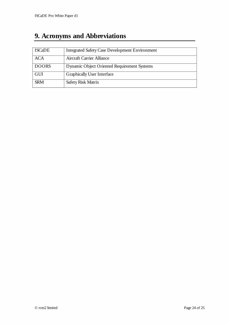
9. Acronyms and Abbreviations ISCaDE Integrated Safety Case Development Environment
ACA Aircraft Carrier Alliance
DOORS Dynamic Object Oriented Requirement Systems
GUI Graphically User Interface
SRM Safety Risk Matrix
© rcm2 limited Page 24 of 25

ISCaDE Pro White Paper d1
10. List of Figures Figure 1: Layered Architecture of ISCaDE™ Pro....................................................................................1 Figure 2: Layered Approach Benefits.......................................................................................................2 Figure 3: Multiple parenting in ISCaDE ..................................................................................................9 Figure 4: A Typical GSN module in ISCaDE (for Railwise case study)...............................................10 Figure 5: GSN diagram for Railwise ......................................................................................................11 Figure 6: Configuration box for GSN diagram.......................................................................................12 Figure 7: Metrics for GSN safety case for Railwise...............................................................................13 Figure 8: Safety Risk Matrix for ACA ...................................................................................................16 Figure 9: Safety Risk Matrix for Defence ..............................................................................................16 Figure 10: Safety Risk Matrix for Railwise............................................................................................17
© rcm2 limited Page 25 of 25