rcu 1000 remote control for vtm and tvm series · rcu 1000 remote control: vtm and tvm series ......
TRANSCRIPT
Revision: C
Delivering the Moment
Installation and Operation Handbook
RCU 1000Remote Control: VTM and TVM SeriesSeptember 2009
061780
Publication Information © 2014 Imagine Communications Corp. Proprietary and Confidential.
Imagine Communications considers this document and its contents to be proprietary and confidential. Except for making a reasonable number of copies for your own internal use, you may not reproduce this publication, or any part thereof, in any form, by any method, for any purpose, or in any language other than English without the written consent of Imagine Communications. All others uses are illegal.
This publication is designed to assist in the use of the product as it exists on the date of publication of this manual, and may not reflect the product at the current time or an unknown time in the future. This pub-lication does not in any way warrant description accuracy or guarantee the use for the product to which it refers.
Imagine Communications reserves the right, without notice to make such changes in equipment, design, specifications, components, or documentation as progress may warrant to improve the performance of the product.
Trademarks Microsoft® and Windows® are registered trademarks of Microsoft Corporation. AMD and Operton are trademarks of Advanced Micro Devices, Inc. Dolby Digital is a registered trademark of Dolby Laboratories. Java is a trademark of Sun Microsystems, Inc. or its subsidiaries in the United States and other countries.All other trademarks and trade names are the property of their respective companies.
Contact Information Imagine Communications has office locations around the world. For locations and contact information see: http://www.imaginecommunications.com/contact us/
Support Contact Information For support contact information see:
▪ Support Contacts: http://www.imaginecommunications.com/services/technical support/
▪ eCustomer Portal: http://support.imaginecommunications.com
Printed September 2009
Item #061780 Rev. C
Copyright © 2006, 2009 by Harris Corporation All rights reserved. Contents of this publication may not be reproduced in any form without permission of Videotek, Inc. This instrument, in whole or in part, may be protected by one or more US (US Patent 6,069,607) or foreign patents or patent applications. Specifications subject to change without notice. Videotek and the Videotek logo are registered trademarks of Videotek, Inc.
RCU 1000 Remote Control: VTM and TVM Series Installation and Operation Handbook

RCU-1000 Installation and Operation Handbook iii Copyright © 2006, 2009, Harris Corporation
Operator’s Safety Summary
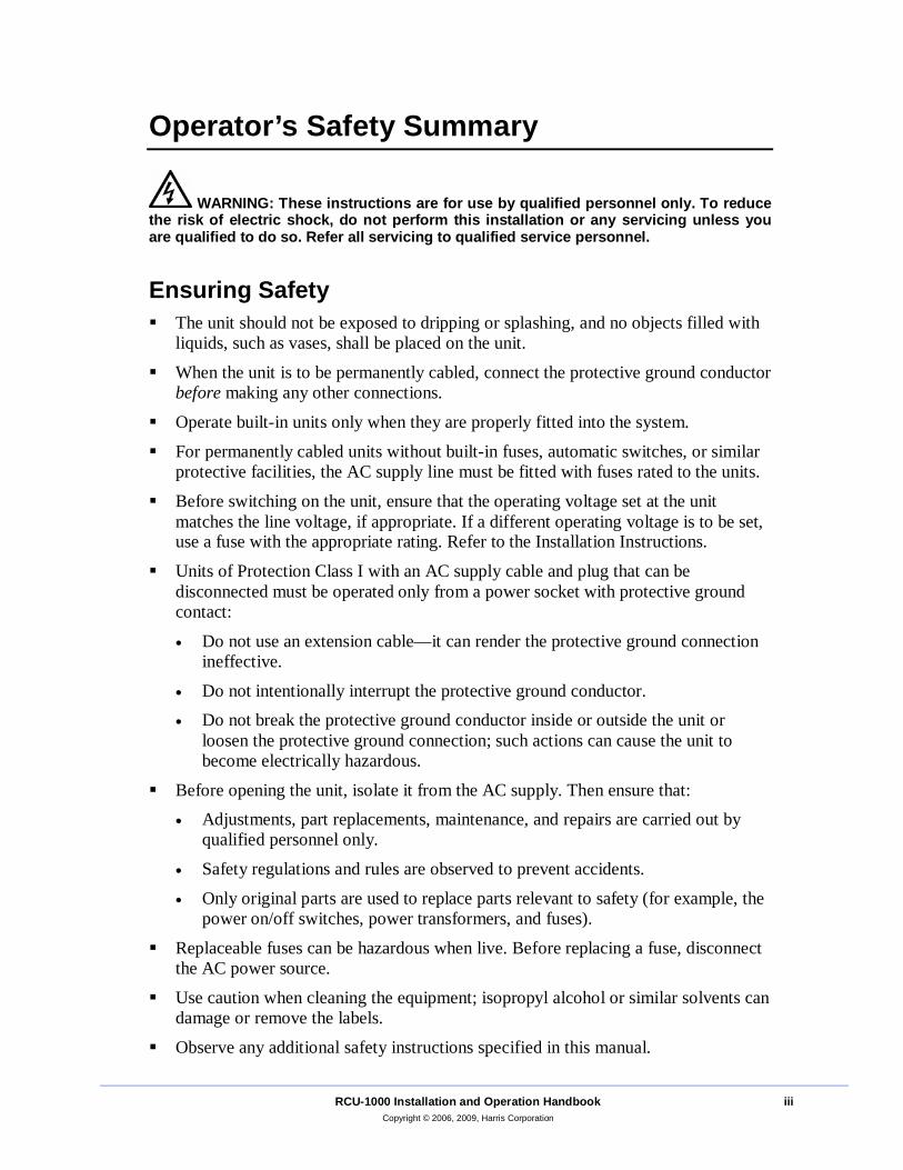
WARNING: These instructions are for use by qualified personnel only. To reduce the risk of electric shock, do not perform this installation or any servicing unless you are qualified to do so. Refer all servicing to qualified service personnel.
Ensuring Safety The unit should not be exposed to dripping or splashing, and no objects filled with
liquids, such as vases, shall be placed on the unit.
When the unit is to be permanently cabled, connect the protective ground conductor before making any other connections.
Operate built-in units only when they are properly fitted into the system.
For permanently cabled units without built-in fuses, automatic switches, or similar protective facilities, the AC supply line must be fitted with fuses rated to the units.
Before switching on the unit, ensure that the operating voltage set at the unit matches the line voltage, if appropriate. If a different operating voltage is to be set, use a fuse with the appropriate rating. Refer to the Installation Instructions.
Units of Protection Class I with an AC supply cable and plug that can be disconnected must be operated only from a power socket with protective ground contact:
• Do not use an extension cable—it can render the protective ground connection ineffective.
• Do not intentionally interrupt the protective ground conductor. • Do not break the protective ground conductor inside or outside the unit or
loosen the protective ground connection; such actions can cause the unit to become electrically hazardous.
Before opening the unit, isolate it from the AC supply. Then ensure that: • Adjustments, part replacements, maintenance, and repairs are carried out by
qualified personnel only.
• Safety regulations and rules are observed to prevent accidents.
• Only original parts are used to replace parts relevant to safety (for example, the power on/off switches, power transformers, and fuses).
Replaceable fuses can be hazardous when live. Before replacing a fuse, disconnect the AC power source.
Use caution when cleaning the equipment; isopropyl alcohol or similar solvents can damage or remove the labels.
Observe any additional safety instructions specified in this manual.
Operator’s Safety Summary
iv RCU-1000 Installation and Operation Handbook Copyright © 2006, 2009, Harris Corporation
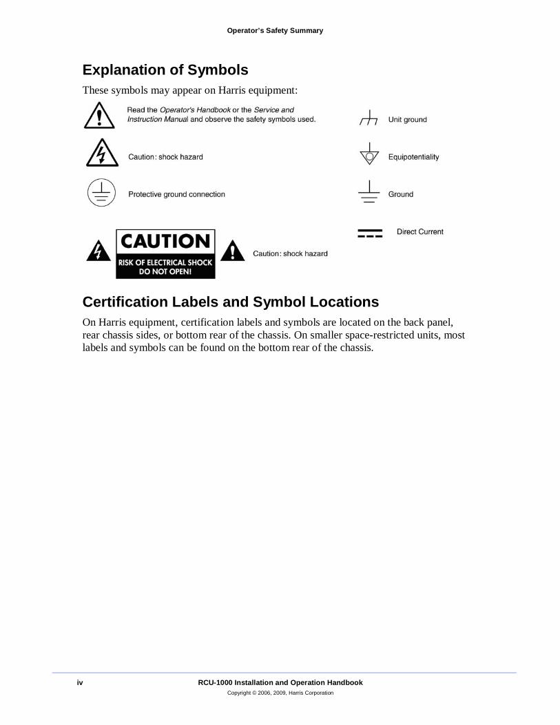
Explanation of Symbols These symbols may appear on Harris equipment:
Certification Labels and Symbol Locations On Harris equipment, certification labels and symbols are located on the back panel, rear chassis sides, or bottom rear of the chassis. On smaller space-restricted units, most labels and symbols can be found on the bottom rear of the chassis.
RCU-1000 Installation and Operation Handbook v Copyright © 2006, 2009, Harris Corporation
Directives and Compliances This section provides information concerning Harris Corporation compliance with EU Directive 2002/95/EC and EU Directive 2002/96/EC.
Restriction on Hazardous Substances (RoHS) Directive 2002/95/EC Directive 2002/95/EC—commonly known as the European Union (EU) Restriction on Hazardous Substances (RoHS)—sets limits on the use of certain substances found in electrical and electronic equipment. The intent of this legislation is to reduce the amount of hazardous chemicals that may leach out of landfill sites or otherwise contaminate the environment during end-of-life recycling. The Directive, which took effect on July 1, 2006, refers to the following hazardous substances:
Lead (Pb)
Mercury (Hg) Cadmium (Cd)
Hexavalent Chromium (Cr-V1) Polybrominated Biphenyls (PBB)
Polybrominated Diphenyl Ethers (PBDE) In accordance with this EU Directive, all Harris products sold in the European Union will be fully RoHS-compliant and “lead-free.” (See the Harris Premier website for more information on dates and deadlines for compliance.) Spare parts supplied for the repair and upgrade of equipment sold before July 1, 2006 are exempt from the legislation. Harris equipment that complies with the EU directive will be marked with a RoHS-compliant symbol, as shown in Figure 1.
Figure 1. RoHS Compliance Symbol
Waste from Electrical and Electronic Equipment (WEEE) Directive 2002/96/EC The European Union (EU) Directive 2002/96/EC on Waste from Electrical and Electronic Equipment (WEEE) deals with the collection, treatment, recovery, and recycling of electrical and electronic waste products. The objective of the WEEE Directive is to assign the responsibility for the disposal of associated hazardous waste to either the producers or users of these products. As of August 13, 2005, producers or users are required to recycle electrical and electronic equipment at end of its useful life,
Directives and Compliances
vi RCU-1000 Installation and Operation Handbook Copyright © 2006, 2009, Harris Corporation
and must not dispose of the equipment in landfills or by using other unapproved methods. (Some EU member states may have different deadlines.)
In accordance with this EU Directive, Harris Corporation and other companies selling electric or electronic devices in the EU will affix labels indicating that such products must be properly recycled.
(See the Harris Premier website for more information on dates and deadlines for compliance.) Contact your local Harris sales representative for information on returning these products for recycling. Harris equipment that complies with the EU directive will be marked with a WEEE-compliant symbol, as shown in Figure 2.
Figure 2. WEEE Compliance Symbol
RCU-1000 Installation and Operation Handbook vii Copyright © 2006, 2009, Harris Corporation
Contents
Operator’s Safety Summary...........................................................................iii Ensuring Safety ............................................................................................. iii Explanation of Symbols ................................................................................. iv Certification Labels and Symbol Locations.................................................... iv
Directives and Compliances...........................................................................v
Restriction on Hazardous Substances (RoHS) Directive 2002/95/EC............ v Waste from Electrical and Electronic Equipment (WEEE) Directive 2002/96/EC .................................................................................................... v
Section 1 ♦ RCU 1000 Remote Control Unit..................................................1
Introduction.....................................................................................................1
Service and Support .......................................................................................1
Section 2 ♦ Installation ...................................................................................3
Section 3 ♦ Operation .....................................................................................5
Operating the RCU 1000................................................................................5 Unit ID ............................................................................................................5
Section 4 ♦ Troubleshooting..........................................................................7
Section 5 ♦ Specifications..............................................................................9
Power Requirements (External Power Supply) ..............................................9
Mechanical .....................................................................................................9 Environmental ................................................................................................9
Standard Accessories.....................................................................................9
Appendix A ♦ Pinouts...................................................................................11
Index ...............................................................................................................13
Contents
viii RCU-1000 Installation and Operation Handbook Copyright © 2006, 2009, Harris Corporation
List of Figures Figure 1-1. RCU 1000 Front and Back Panel Views.......................................1
Figure 2-1. Connecting the RCU to Multiple VTM/TVMs ................................4 Figure A-1. RCU 1000 to Main Unit RJ-11 Connector ..................................11
List of Tables Table 1-1. Description of RCU 1000 Back Panel Connectors.........................1 Table 4-1. Problems, Causes, and Solutions..................................................7
Table A-1. Pinouts for RCU 1000 TO Main Unit Connector..........................11
RCU-1000 Installation and Operation Handbook 1 Copyright © 2006, 2009, Harris Corporation
Section 1 ♦ RCU 1000 Remote Control Unit
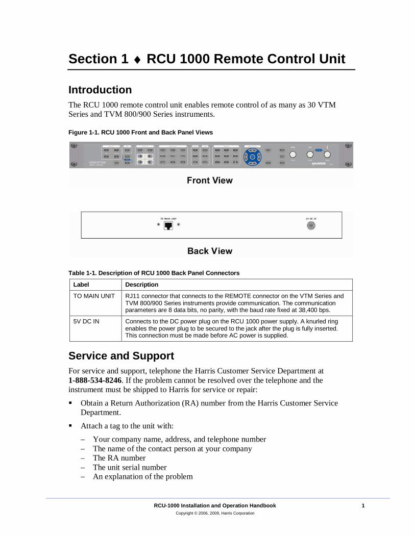
Introduction The RCU 1000 remote control unit enables remote control of as many as 30 VTM Series and TVM 800/900 Series instruments.
Figure 1-1. RCU 1000 Front and Back Panel Views
Table 1-1. Description of RCU 1000 Back Panel Connectors
Label Description
TO MAIN UNIT RJ11 connector that connects to the REMOTE connector on the VTM Series and TVM 800/900 Series instruments provide communication. The communication parameters are 8 data bits, no parity, with the baud rate fixed at 38,400 bps.
5V DC IN Connects to the DC power plug on the RCU 1000 power supply. A knurled ring enables the power plug to be secured to the jack after the plug is fully inserted. This connection must be made before AC power is supplied.
Service and Support For service and support, telephone the Harris Customer Service Department at 1-888-534-8246. If the problem cannot be resolved over the telephone and the instrument must be shipped to Harris for service or repair:
Obtain a Return Authorization (RA) number from the Harris Customer Service Department.
Attach a tag to the unit with: − Your company name, address, and telephone number − The name of the contact person at your company − The RA number − The unit serial number − An explanation of the problem
Section 1 ♦ RCU 1000 Remote Control Unit
2 RCU-1000 Installation and Operation Handbook Copyright © 2006, 2009, Harris Corporation
To prevent shipping damage, pack the unit the same way Harris had packed it. If possible, use the original packing materials in the original shipping container.
Ship the unit to Harris Corporation Videotek Test and Measurement 243 Shoemaker Road Pottstown, PA 19464-6433 Attn: RA xxxx (where x is the RA number)
Email: [email protected]
RCU-1000 Installation and Operation Handbook 3 Copyright © 2006, 2009, Harris Corporation
Section 2 ♦ RCU 1000 Installation To install the RCU 1000, follow these steps: 1. Connect the DC power supply to the 5V DC IN connector.
2. Connect the power cord to a properly grounded AC outlet. 3. Verify that the front panel buttons flash. If they do not, check steps 1 and 2.
4. If multiple VTM or TVM instruments are being connected, ensure each VTM/TVM has a unique unit ID (from 1-99) before connecting them to the REMOTE bus. The UNIT ID submenu is located in the COMMUNICATIONS menu. See Unit ID on page 1-5 for more information on Unit ID.
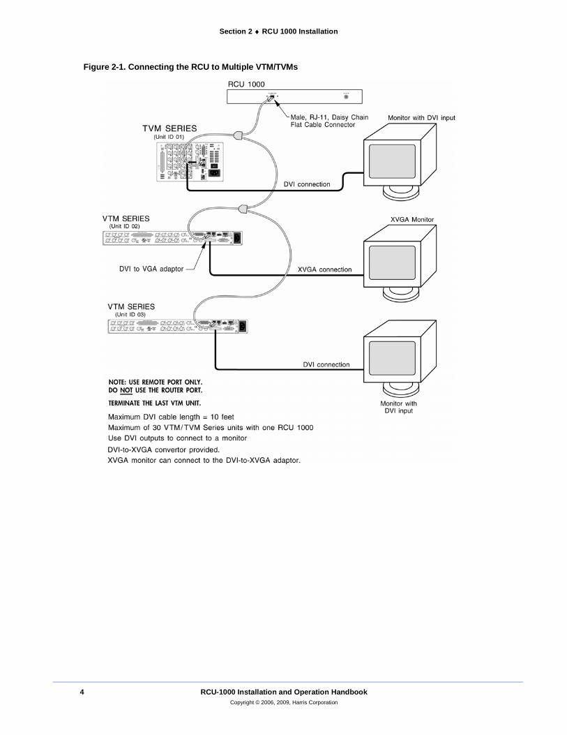
5. Physically connect the RCU 1000 to a bus with one or more VTM/TVM instruments using a multidrop cabling adaptor and straight through cable using RJ-11 connectors (not a standard telephone wire) that connects to the REMOTE ports on the back of the VTM/TVM Series instruments and to the TO MAIN UNIT connector on the back of the RCU, as illustrated in Figure 2-1. The RCU 1000 must be at one end of the RS-422 bus. The last VTM/TVM instrument must be terminated at the other end by selecting TERMINATION in the COMMUNICATIONS\RCU PORT menu.
6. Once connected, select the VTM/TVM Series instrument to be controlled by the RCU 1000 by pressing SETUP and LINE on the RCU 1000 simultaneously (the VTM Series selection mode is restricted to the RCU 1000). While in the selection mode, the LINE button flashes.
7. Rotate the CURVED ARROW knob until the Unit ID in the RCU matches the UNIT ID selection in the attached VTM/TVM Series instrument to be controlled.
8. When communication is established between the RCU 1000 and the VTM/TVM Series instrument(s), the RCU 1000 buttons will stop flashing in alternate pairs. The RCU 1000 text now reflects the settings of the attached VTM/TVM Series instrument. The RCU 1000 front panel operations affect the VTM/TVM Series instrument.
9. The VTM/TVM polls the selected RCU 1000 every five seconds. If the VTM/TVM Series instrument fails to receive the poll, the RCU 1000 assumes that a communication break has occurred.
The front panel buttons flashing indicates a communication break. When communication is once again established, the INPUT buttons will reflect the current setting.
Section 2 ♦ RCU 1000 Installation
4 RCU-1000 Installation and Operation Handbook Copyright © 2006, 2009, Harris Corporation
Figure 2-1. Connecting the RCU to Multiple VTM/TVMs
RCU-1000 Installation and Operation Handbook 5 Copyright © 2006, 2009, Harris Corporation
Section 3 ♦ RCU 1000 Operation
Operating the RCU 1000 Operating the RCU 1000 is the same as operating a VTM/TVM Series instrument with one exception: selecting a VTM/TVM Series instrument for communication.
To select a VTM/TVM Series instrument for communication: 1. Press the SETUP and LINE buttons simultaneously to enable the selection mode.
The LINE button will flash.
2. Rotate the CURVED ARROW knob to select the Unit ID. Rotating clockwise scans UP through the UNIT IDs. Rotating counterclockwise scans down through the unit IDs.
Unit ID The unit ID is the identification number of the TVM or VTM series instrument. It can be set to any number within a range of 1 to 99 and should be different than the identification numbers of other units in the same system configuration.

Section 3 ♦ RCU 1000 Operation
6 RCU-1000 Installation and Operation Handbook Copyright © 2006, 2009, Harris Corporation
This page is intentionally blank.
RCU-1000 Installation and Operation Handbook 7 Copyright © 2006, 2009, Harris Corporation
Section 4 ♦ RCU 1000 Troubleshooting
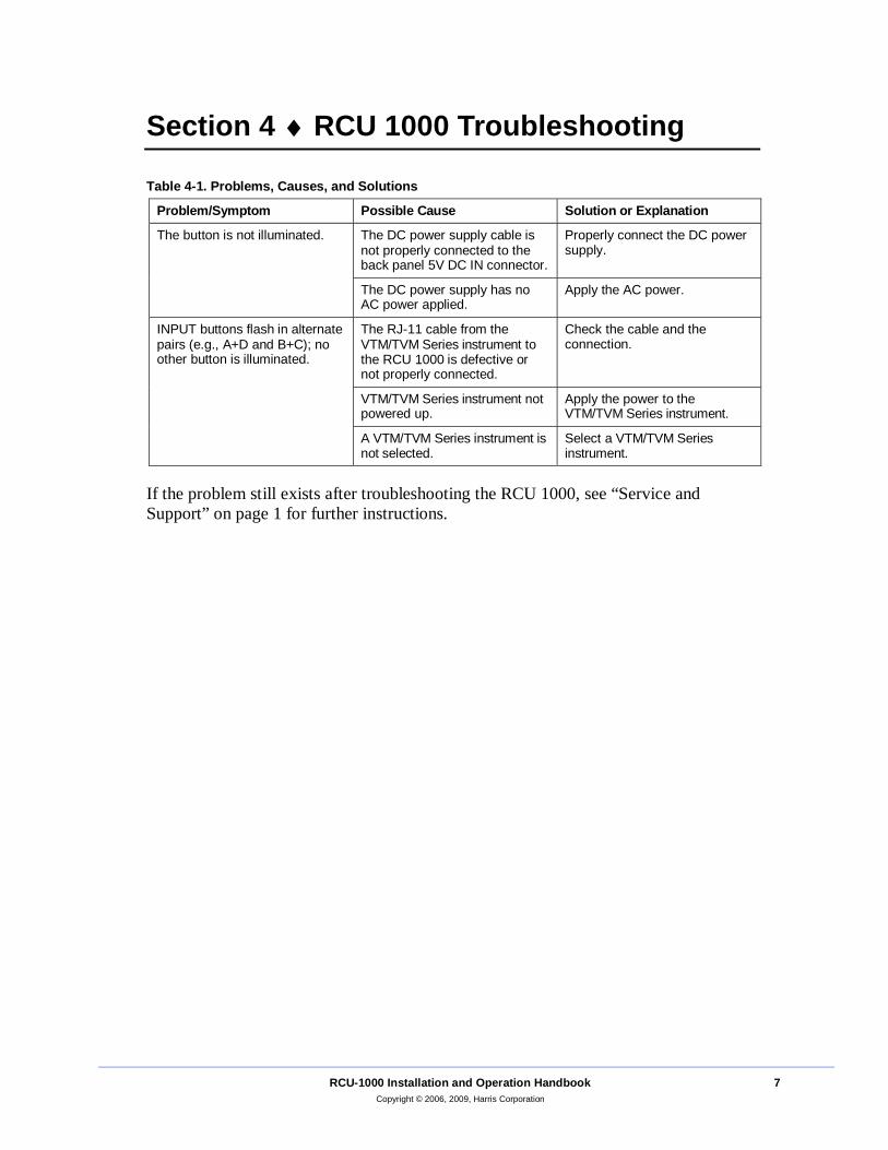
Table 4-1. Problems, Causes, and Solutions
Problem/Symptom Possible Cause Solution or Explanation
The DC power supply cable is not properly connected to the back panel 5V DC IN connector.
Properly connect the DC power supply.
The button is not illuminated.
The DC power supply has no AC power applied.
Apply the AC power.
The RJ-11 cable from the VTM/TVM Series instrument to the RCU 1000 is defective or not properly connected.
Check the cable and the connection.
VTM/TVM Series instrument not powered up.
Apply the power to the VTM/TVM Series instrument.
INPUT buttons flash in alternate pairs (e.g., A+D and B+C); no other button is illuminated.
A VTM/TVM Series instrument is not selected.
Select a VTM/TVM Series instrument.
If the problem still exists after troubleshooting the RCU 1000, see “Service and Support” on page 1 for further instructions.

Section 4 ♦ RCU 1000 Troubleshooting
8 RCU-1000 Installation and Operation Handbook Copyright © 2006, 2009, Harris Corporation
This page is intentionally blank.
RCU-1000 Installation and Operation Handbook 9 Copyright © 2006, 2009, Harris Corporation
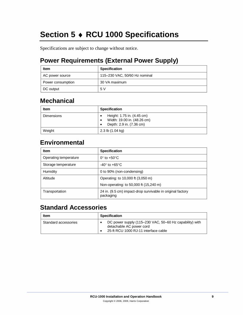
Section 5 ♦ RCU 1000 Specifications Specifications are subject to change without notice.
Power Requirements (External Power Supply) Item Specification
AC power source 115–230 VAC, 50/60 Hz nominal
Power consumption 30 VA maximum
DC output 5 V
Mechanical Item Specification
Dimensions • Height: 1.75 in. (4.45 cm) • Width: 19.00 in. (48.26 cm) • Depth: 2.9 in. (7.36 cm)
Weight 2.3 lb (1.04 kg)
Environmental Item Specification
Operating temperature 0° to +50°C
Storage temperature -40° to +65°C
Humidity 0 to 90% (non-condensing)
Altitude Operating: to 10,000 ft (3,050 m)
Non-operating: to 50,000 ft (15,240 m)
Transportation 24 in. (9.5 cm) impact-drop survivable in original factory packaging
Standard Accessories Item Specification
Standard accessories
• DC power supply (115–230 VAC, 50–60 Hz capability) with detachable AC power cord
• 25-ft RCU 1000 RJ-11 interface cable

Section 5 ♦ RCU 1000 SpecificationsSection 5 ♦ RCU 1000 Specifications
10 RCU-1000 Installation and Operation Handbook Copyright © 2006, 2009, Harris Corporation
This page is intentionally blank.
RCU-1000 Installation and Operation Handbook 11 Copyright © 2006, 2009, Harris Corporation
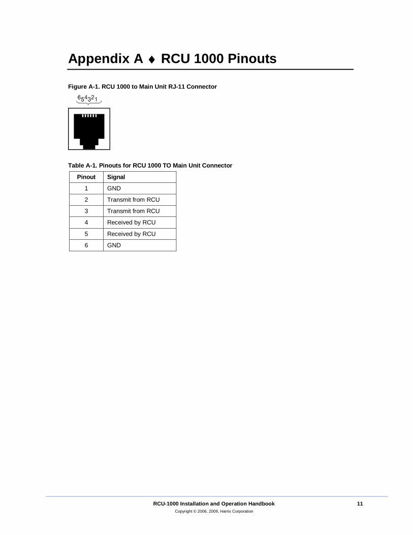
Appendix A ♦ RCU 1000 Pinouts
Figure A-1. RCU 1000 to Main Unit RJ-11 Connector
Table A-1. Pinouts for RCU 1000 TO Main Unit Connector
Pinout Signal
1 GND
2 Transmit from RCU
3 Transmit from RCU
4 Received by RCU
5 Received by RCU
6 GND

Appendix A ♦ RCU 1000 Pinouts
12 RCU-1000 Installation and Operation Handbook Copyright © 2006, 2009, Harris Corporation
This page is intentionally blank.
RCU-1000 Installation and Operation Handbook 13 Copyright © 2006, 2009, Harris Corporation
Index Compliances, v
Customer Service, 1 Directives, v
Installation, 3 Operation, 5
Pinouts, 11 RA. See Return Authorization
RCU 1000 Installation, 3
Introduction, 1 Multi Connection, 4
Operation, 5 Panel Views, 1
Pinouts, 11
Safety symbols, iv
Specifications, 9 Troubleshooting, 7
RCU 1000 to main unit connector pinouts, 11
Return Authorization, 1 Safety, iii
Service, 1 Shipment
Returning to Harris Corporation, 2 Specifications, 9
Troubleshooting, 7

Index
14 RCU-1000 Installation and Operation Handbook Copyright © 2006, 2009, Harris Corporation
This page is intentionally blank.


Item Number 061780 Rev. C
Printed 09/09