re-curing of calcium aluminate cements post contact with
TRANSCRIPT

17th EMABM, University of Toronto, Toronto, Canada, May 20-23, 2019
236
Re-curing of calcium aluminate cements post contact with molten slag
Fernando F. de Mendonca Filho, Delft University of Technology, Materials & Environment (CiTG), Delft, The Netherlands, [email protected]
Oğuzhan Çopuroglu, Delft University of Technology, Materials & Environment (CiTG), Delft, The Netherlands, [email protected]
INTRODUCTION
Calcium aluminate cements (CAC) are widely used for the production of refractory concretes that are able to withstand extreme temperatures [1]. During exposure to such temperatures, the main hydration phases revert to mayenite, calcium aluminate and calcium dialuminate. Many investigations [2-4] focused on the description of this mechanism and how it affects the remaining mechanical properties of the concrete. However, subsequent contact with air humidity after high temperature exposure further modifies the composition of the cement paste [5]. The effects of re-hydration on the pore network and mechanical properties of concrete are critical to the design of durable systems under repeated exposure to high temperatures, as well as assessing the remaining quality of damaged structures. Yet such effects remain poorly understood.
This research focuses on the use of CAC as a compatible protection layer to concrete made with ordinary Portland cement (OPC) in order to sustain infrastructure in industries which may have occasional or even constant high temperature spills (such as steel, aluminum, petro-chemicals and others). To achieve such goal, slabs with one layer composed of CAC mortar and a second layer made of OPC mortar will be subjected to contact with molten glass at 1530°C followed by exposure to ambient moisture in a fog room. The microstructure of these samples will then be studied and compared.
MATERIALS AND METHODS
Laboratory scale slabs were prepared containing two layers, one of approximately three years old OPC based concrete and one of CAC mortar (Figure 1). For the OPC concrete, cubic samples of 10 cm sides were sawn to 3 cm height. These samples had a w/c ratio, cement content and aggregate maximum size of 0.45, 355 kg/m3 and 32 mm, respectively. The cement used for fabrication was CEM III/B 42,5 N and all samples were cured in a fog room at RH>95% for 28 days. For the layer of CAC mortar, the cement REFRO50 (CIMSA) was used in combination with Glenium 51 (BASF), the mix proportions for cement, aggregate, water and super plasticizer were 1:1.35:0.2:0.004. The composition of REFRO50 can be found in Table 1.
17th Euroseminar on Microscopy Applied to Building Materials
237
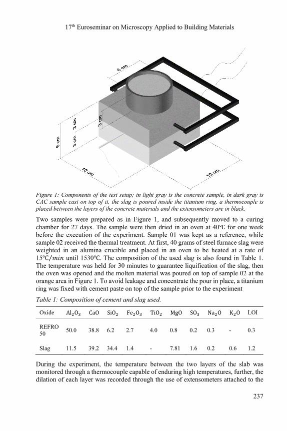
Figure 1: Components of the test setup; in light gray is the concrete sample, in dark gray is CAC sample cast on top of it, the slag is poured inside the titanium ring, a thermocouple is placed between the layers of the concrete materials and the extensometers are in black.
Two samples were prepared as in Figure 1, and subsequently moved to a curing chamber for 27 days. The sample were then dried in an oven at 40℃ for one week before the execution of the experiment. Sample 01 was kept as a reference, while sample 02 received the thermal treatment. At first, 40 grams of steel furnace slag were weighted in an alumina crucible and placed in an oven to be heated at a rate of 15℃ 𝑚𝑖𝑛⁄ until 1530℃. The composition of the used slag is also found in Table 1. The temperature was held for 30 minutes to guarantee liquification of the slag, then the oven was opened and the molten material was poured on top of sample 02 at the orange area in Figure 1. To avoid leakage and concentrate the pour in place, a titanium ring was fixed with cement paste on top of the sample prior to the experiment
Table 1: Composition of cement and slag used.
Oxide Al O CaO SiO Fe O TiO MgO SO Na O K O LOI
REFRO 50
50.0 38.8 6.2 2.7 4.0 0.8 0.2 0.3 - 0.3
Slag 11.5 39.2 34.4 1.4 - 7.81 1.6 0.2 0.6 1.2
During the experiment, the temperature between the two layers of the slab was monitored through a thermocouple capable of enduring high temperatures, further, the dilation of each layer was recorded through the use of extensometers attached to the

17th EMABM, University of Toronto, Toronto, Canada, May 20-23, 2019
238
sample. All measurements had a rate of once per second over two hours, after which the slag and sample cooled down and could be handled.
Sample 01 was sawn into 30 x 20 x 10 mm specimen parallel to the height of the sample as seen in Figure 1. The specimen was then vacuum impregnated with epoxy resin and further ground and polished until a flat surface was achieved. Finally, a 10 nm layer of conducting carbon coating was placed on the top of the polished surface using a Leica EM CEDO030 carbon evaporator. Sample 02 was first cut in half, one half of the sample went through identical process as sample 01. The other half had the sawn face sealed with aluminum tape and was moved to a curing room where it was cured for one week. Thereafter, the second half was also prepared for microanalysis.
The polished sections were analyzed through the use of BSE (backscattered electron) imaging and energy dispersive x-ray spectroscopy (EDS). For the EDS analyses, a Philips XL30 was used under high vacuum, the take-off angle was 35.3 and sample to detector distance was 10 mm. The detector was a SUTW (sapphire) with a calibrated resolution of 132 eV, the accelerating voltage was set at 15 kV and the deadtime remained at approximately 10%. Previous to the acquisition of spectra, the beam current was measured using a Faraday cup and a picoammeter.
The interaction volume of most phases was modeled using CASINO_v2 and all volumes were estimated between 3 and 6 microns for the mentioned accelerating voltage. After acquisition all spectra were corrected using ZAF algorithm with the aid of NIST DTSA-II software. The quantification of mass and atomic percentages was standard based, using the minerals shown in Table 2.
Table 2: Minerals used for standard based corrections.
Element Symbol Mineral used for correction Chemical composition
Sodium Na Albite NaAlSi O
Magnesium Mg Periclase MgO
Aluminum Al Jadeite NaAlSi O
Silicon Si Quartz SiO
Sulfur S Anhydrite CaSO
Potassium K Sanidine KAlSi O
Calcium Ca Calcite CaCO
Titanium Ti Rutile TiO
Iron Fe Haematite Fe O
Oxygen O Oxygen was determined by stoichiometry

17th Euroseminar on Microscopy Applied to Building Materials
239
RESULTS AND DISCUSSION
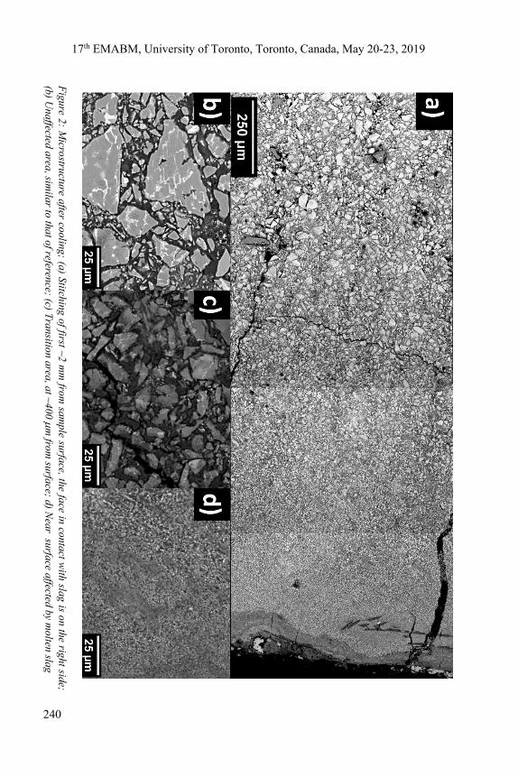
The effect of pouring molten slag on the surface of the sample can be observed in its microstructure for the first 1,5 mm of the sample as shown in Figure 2. There are several shrinkage cracks and a clear refinement of the unhydrated grains to the point of mixing with hydration products in components smaller than 1 m. EDS performed on the products between the unhydrated grains showed that the composition had a significant increase in the amount of magnesium and silica in comparison with the reference sample. The main phase continued to be 𝐶𝐴𝐻 , as in the reference sample, but the Si/Ca atomic ratio increased from 0.1 to 1.0, which could point to a temporary mixing of slag as an amorphous phase. This observation is corroborated by the doubling of average Mg content when comparing sample 01 and 02, further, the magnesium quantified in the surface of sample 02 is ten times higher than when millimeters deep with respect to the face that was in contact with molten slag.
For the sample that went through re-curing, the regions near the surface presented a very complex microstructure, as it can be seen in Figure 3 a), which included the surface coated with a layer of 𝐶𝐴𝐻 embedded in amorphous alumina gel (𝐴𝐻 ) and 𝐶𝑎𝐶𝑂 from atmospheric carbonation of the calcium aluminates. Instead of the zone with very fine components, an extremely porous zone was observed, in which most of the unhydrated grains seem to have been completely consumed leaving only 𝐶𝐴𝐻 , then an area in which the 𝐶𝐴 and 𝐶𝐴 grains present a smaller granulometry, as in sample 02, and finally a seemingly unaffected area, resembling sample 01. Further, many of the cracks were filled by 𝐴𝐻 and in smaller volume by 𝐶𝐴𝐻 and 𝑆𝑖𝑂 , this can be observed at the bottom of Figure 3 a) and in Figure 3 d).
The composition of the hydration products presented increased Mg content, while the amount of Si dropped to values equivalent to the reference sample. The decrease in amount of silicon can be explained by areas in which solid silica precipitations were identified. An example of such areas is shown in Figure 3 b). Inside large cracks and the surface of the sample, freshly formed calcium aluminate decahydrate can be identified by needle morphology as described in [6], which can be seen in Figure 3 c).
No indication of conversion reactions was found, although some particles of 𝐶 𝐴𝐻 were observed embedded in 𝐴𝐻 , those had a very high amount of Si and slight presence of S. Those phases are seen in Figure 3 b) and c). Given their abundance in Si, it is possible that those phases were actually an analogue to Hydrogarnet (𝐶 𝐴𝑆 𝐻 ) or even Gehlenite (𝐶 𝐴𝑆𝐻 ) as described in [7].
17th EMABM, University of Toronto, Toronto, Canada, May 20-23, 2019
240
Figure 2: M
icrostructure after cooling; (a) Stitching of first ~2 mm
from sam
ple surface, the face in contact with slag is on the right side;
(b) Unaffected area, sim
ilar to that of reference; (c) Transition area, at ~400
m from
surface; d) Near surface affected by m
olten slag

17th Euroseminar on Microscopy Applied to Building Materials
241
Fig
ure
3: M
icro
stru
ctur
e af
ter
one
wee
k cu
ring
; a)
Sti
tchi
ng o
f fir
st m
m fr
om s
ampl
e su
rfac
e, th
e fa
ce in
con
tact
with
sla
g is
on
the
left
side
;b)
Nea
r su
rfac
e w
ith
sili
ca p
reci
pita
tes;
c)
Cra
cked
zon
e w
ith
CA
H_1
0 n
eedl
es;
d) Z
one
with
AH
_3-f
ille
d m
icro
crac
ks.

17th EMABM, University of Toronto, Toronto, Canada, May 20-23, 2019
242
CONCLUSION
This study observes the influence of re-curing after contact of CAC with molten slag at ultra-high temperature. It was found that slag tends to mix with the cement paste in fine unstable solid solutions, after re-curing, these solutions partially dissipate and precipitate silica grains. Further, other elements carried by the slag (such as magnesium) seem to remain in the paste. Although re-curing filled many cracks with hydration products, it seems to also create a very porous zone on the surface of the damaged zone, so the effects on porosity seem to be progressive. At this scale, the CAC layer worked as a good insulating protection to the OPC concrete and no adverse effects were observed in this layer, however, at industrial scale high temperatures can remain for longer periods, increasing the duration of possible mixing.
This paper presents preliminary results of an on-going research. Following steps envision to perform molecular analysis in similar samples to better determine which crystals are being formed before and after re-curing. Further, the mechanical properties of these phases will be determined in order to understand how the process might change the bulk material behaviour.
ACKNOWLEDGEMENTS
The authors would like to thank the Oxystaalfabriek 2 from Tata steel for financial support and CIMSA for the calcium aluminate cement
REFERENCES
[1] Luz, A. P., Braulio, M. A. L., Pandolfelli, V. C. (2015). Refractory Castable Engineering. Goller Verlag GmbH, Baden-Baden, Germany. [2] Lee, N. K., Koh, K. T., Park, S. H., & Ryu, G. S. (2017). Microstructural investigation of calcium aluminate cement-based ultra-high performance concrete (UHPC) exposed to high temperatures. Cement and Concrete Research, 102(August), 109–118. https://doi.org/10.1016/j.cemconres.2017.09.004 [3] Vejmelková, E., Koňáková, D., Scheinherrová, L., Doleželová, M., Keppert, M., & Černý, R. (2018). High temperature durability of fiber reinforced high alumina cement composites. Construction and Building Materials, 162, 881–891. https://doi.org/10.1016/j.conbuildmat.2018.01.076 [4] Rambo, D. A. S., de Andrade Silva, F., Toledo Filho, R. D., & da Fonseca Martins Gomes, O. (2015). Effect of elevated temperatures on the mechanical behavior of basalt textile reinforced refractory concrete. Materials and Design, 65, 24–33. https://doi.org/10.1016/j.matdes.2014.08.060 [5] Akca, A. H., & Özyurt, N. (2018). Effects of re-curing on microstructure of concrete after high temperature exposure. Construction and Building Materials, 168, 431–441. https://doi.org/10.1016/j.conbuildmat.2018.02.122
17th Euroseminar on Microscopy Applied to Building Materials
243
[6] Geng, G., Li, J., Yu, Y., Shapiro, D. A., Kilcoyne, D. A. L., & Monteiro, P. J. M. (2017). Nanometer-Resolved Spectroscopic Study Reveals the Conversion Mechanism of CaOꞏAl2O3ꞏ10H2O to 2CaOꞏAl2O3ꞏ8H2O and 3CaOꞏAl2O3ꞏ6H2O at an Elevated Temperature. Crystal Growth and Design, 4253(1). https://doi.org/10.1021/acs.cgd.7b00553 [7] Hidalgo, A., Petit, S., García Calvo, J. L., Alonso, C., & Andrade, C. (2007). Microstructure of the system calcium aluminate cement-silica fume: application in waste immobilization. Studies in Surface Science and Catalysis (Vol. 170). Elsevier B.V. https://doi.org/10.1016/S0167-2991(07)81039-1