re-engineering of an industrial grade heat exchanger
TRANSCRIPT

Design of an Improved
Bayonet Ultra Heat Exchanger
Team 11
5/1/12

Team Members
• Harshith D'mello
• Dylan Herman
• James Hum
• Kent Yee Lui
• James Sowin
Speaker: H. D’Mello
5/1/2012 Team 11 – Heat Exchanger 2

Acknowledgements• Prof. Chia-Fon Lee
• Prof. Stephen Platt
• Prof. Emad Jassim
• Lance Hibbeler
• Seid Koric and Ahmed Taha
• Jay Menacher
• Ralf Möller, Keith Parrish and their dedicated
team of machinists
• Eclipse Inc, specifically Val Smirnov, Rick
Wenger, Jason Smith and Andrew Fortener
Speaker: H. D’Mello
5/1/2012 Team 11 – Heat Exchanger 3
Overview
• Introduction
• Proposed Solution
• Computational Fluid Dynamics Analysis
• Experimental Testing
• Energy Savings Estimate
• Cost Analysis
• Budget
• Conclusions and Recommendations
Speaker: H. D’Mello
5/1/2012 Team 11 – Heat Exchanger 4

Introduction
Original BU
Speaker: H. D’Mello
5/1/2012 Team 11 – Heat Exchanger 5

Background• Bayonet Ultra (BU) heat exchanger
o Used in industrial burners
o Typical operating temperature between
1500 - 2200 °F
o Implemented in furnaces, used to heat
ambient air
o Saves fuel in burner by recuperating heat
from exhaust gases
o Typically single tube, but BU series is
predominantly multitube
Speaker: H. D’Mello
5/1/2012 Team 11 – Heat Exchanger 6

Project Goals
• Increase the effectiveness of the original BU
o Robust
o Maintain pressure drops
o Easily manufacturable
o Maintain current exterior dimensions
Speaker: H. D’Mello
5/1/2012 Team 11 – Heat Exchanger 7
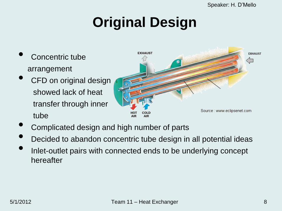
• Concentric tube
arrangement
• CFD on original design
showed lack of heat
transfer through inner
tube
• Complicated design and high number of parts
• Decided to abandon concentric tube design in all potential ideas
• Inlet-outlet pairs with connected ends to be underlying concept
hereafter
Original Design
Speaker: H. D’Mello
5/1/2012 Team 11 – Heat Exchanger 8

Proposed Solution
Speaker: H. D’Mello
5/1/2012 Team 11 – Heat Exchanger 9

Explanation of Decision Matrix
• Decision matrix created to rank design concepts
• 5 categories (weight)o No. of parts (10)
o No. of welds (10)
o Machinability (10)
o Scalability (5)
o Pressure Drop (15)
• Ranking from 1 to 5
• Maximum score of 250
Speaker: H. D’Mello
5/1/2012 Team 11 – Heat Exchanger 10

First Concept
• Circular bends
• 12 tubes, 6 inlet-outlet pairs
• Min. bend radius for safe tube
bending is 1.5 times tube
diameter
• Decision matrix result
• Score: 130
• Rank: 4
Speaker: H. D’Mello
5/1/2012 Team 11 – Heat Exchanger 11

Second Concept
• Compartments of four tubes
(two inlets and two outlets)
• Welding torch of 12 mm
diameter has to weld on inside
• Impossible to weld airtight
• Decision matrix result
• Score: 140
• Rank: 3
Speaker: H. D’Mello
5/1/2012 Team 11 – Heat Exchanger 12
Third Concept
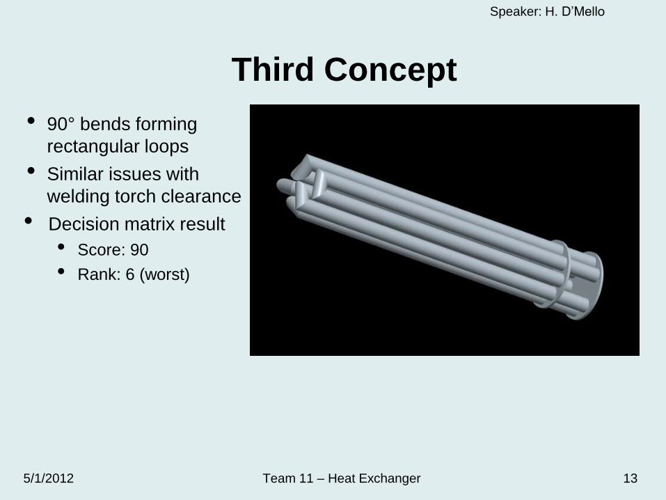
• 90° bends forming
rectangular loops
• Similar issues with
welding torch clearance
• Decision matrix result
• Score: 90
• Rank: 6 (worst)
Speaker: H. D’Mello
5/1/2012 Team 11 – Heat Exchanger 13
Fourth Concept
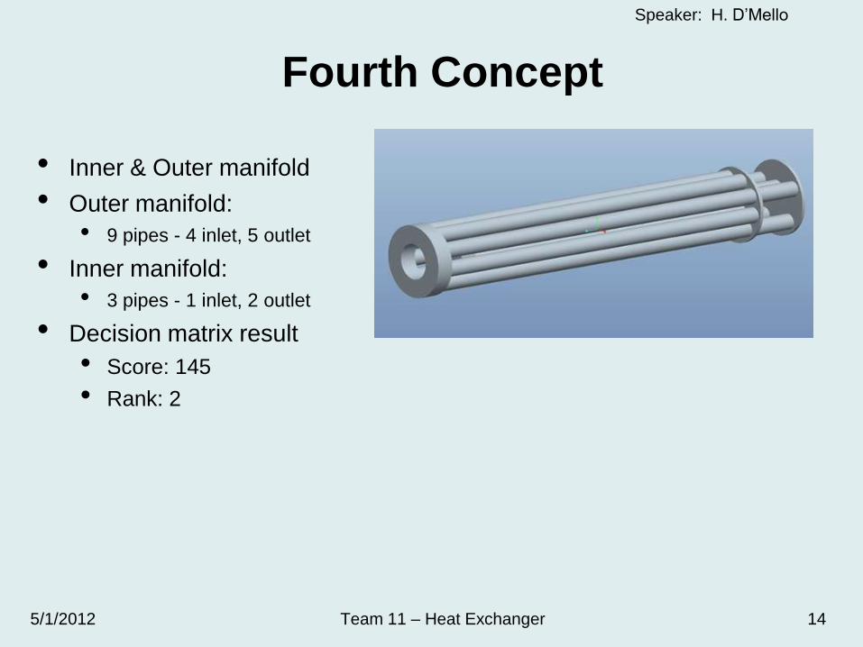
• Inner & Outer manifold
• Outer manifold:
• 9 pipes - 4 inlet, 5 outlet
• Inner manifold:
• 3 pipes - 1 inlet, 2 outlet
• Decision matrix result
• Score: 145
• Rank: 2
Speaker: H. D’Mello
5/1/2012 Team 11 – Heat Exchanger 14
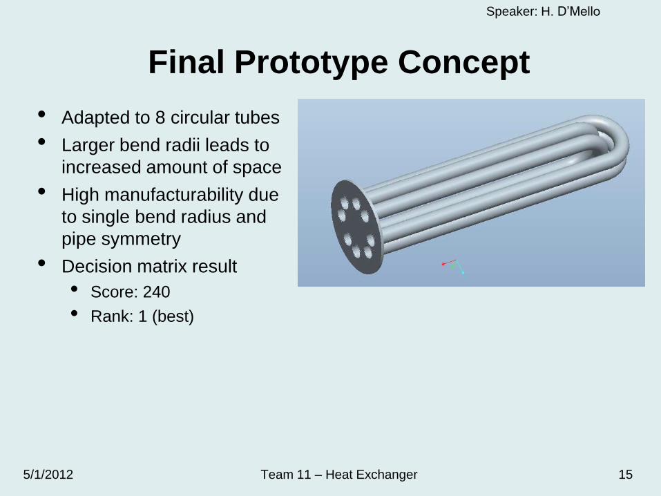
Final Prototype Concept
• Adapted to 8 circular tubes
• Larger bend radii leads to
increased amount of space
• High manufacturability due
to single bend radius and
pipe symmetry
• Decision matrix result
• Score: 240
• Rank: 1 (best)
Speaker: H. D’Mello
5/1/2012 Team 11 – Heat Exchanger 15

Final Design Concept Flow Path
Compartment at hot air outlet quickens exit
of preheated air, preventing loss of heat to
cold air inlet section
Speaker: H. D’Mello
5/1/2012 Team 11 – Heat Exchanger 16
Exhaust Out
Exhaust In
Cold Air Inlet
Hot Air Outlet

Computational Fluid
Dynamics (CFD)
Analysis
Speaker: J. Hum
5/1/2012 Team 11 – Heat Exchanger 17

Design Models• Include exchanger tubes and
exhaust gas only
• Design 3 - 45° Welded Bends
• Design 4 – Ring Manifolds
Speaker: J. Hum
5/1/2012 Team 11 – Heat Exchanger 18

Design Models
Speaker: J. Hum
5/1/2012 Team 11 – Heat Exchanger 19

Computational Comparison
Speaker: J. Hum
5/1/2012 Team 11 – Heat Exchanger 20
Original BU – Symmetry
Prototype BU
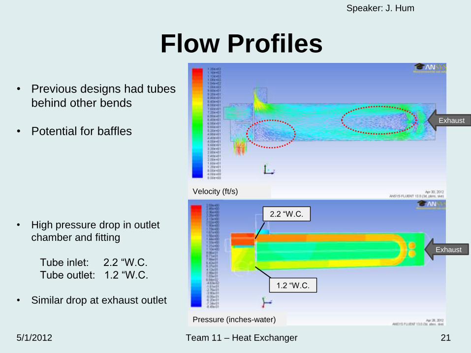
Flow Profiles
• Previous designs had tubes
behind other bends
• Potential for baffles
• High pressure drop in outlet
chamber and fitting
Tube inlet: 2.2 “W.C.
Tube outlet: 1.2 “W.C.
• Similar drop at exhaust outlet
Pressure (inches-water)
1.2 “W.C.
2.2 “W.C.
Speaker: J. Hum
5/1/2012 Team 11 – Heat Exchanger 21
Velocity (ft/s)
Exhaust
Exhaust

Prototype Experimental Comparison
Speaker: J. Hum
5/1/2012 Team 11 – Heat Exchanger 22

Experimental
Testing
Speaker: J. Sowin
5/1/2012 Team 11 – Heat Exchanger 23

Test Procedure•Exhaust air simulating 200-350 kBtu/hr with 12% excess air
•Three flow rates varying the exhaust temperatures from 700-1100°F
•Temperatures measured at all inlets, outlets and on tubes with thermocouples
•Flow rates measured for exhaust and pre-heat air by an orifice plate pressure drop
•Pressure drops measured for exhaust and pre-heat air with manometers
Electric
Heaters
Pre-Heat Air
Blower
Insulated BU
Recuperator
Orifice Flowmeter
K-type
Thermocouple
Wires
Speaker: J. Sowin
5/1/2012 Team 11 – Heat Exchanger 24

•9 K-type thermocouples: spaced throughout the BU
•Temperature read out from electric heater
•2 Orifices : placed 4 feet from blowers, pressure drop measured by
manometer
•2 Static pressure manometers: placed at exhaust inlet and pre-heated air inlet
Thermocouple Placements
Speaker: J. Sowin
5/1/2012 Team 11 – Heat Exchanger 25

Experimental Results
Average Effectiveness Overall = 22% for original BU
Average Effectiveness Overall = 26% for redesigned BU
Effectiveness
Speaker: J. Sowin
5/1/2012 Team 11 – Heat Exchanger 26

Experimental ResultsAir Pressure Drop
Speaker: J. Sowin
5/1/2012 Team 11 – Heat Exchanger 27
Energy Savings
Estimate
Speaker: K. Lui
5/1/2012 Team 11 – Heat Exchanger 28

Assumptions
• BU heat exchanger run time o Eight hours per day
o 365 days per year
• Propane is used as the fuel gaso Energy content = 91,690 Btu/gal [1]
o Cost = $2.05/gal (Feb 2011) [2]
• Comparing old and new designs in terms ofo Increased energy savings (energy saved)
o Reduced cost (cost saved)
[1] Energy Density of Propane
http://hypertextbook.com/facts/2002/EricLeung.shtml
[2] Propane Prices by Sales Type, U.S. Energy Information Administration
http://www.eia.gov/dnav/pet/pet_pri_prop_dcu_nus_m.htm
Speaker: K. Lui
5/1/2012 Team 11 – Heat Exchanger 29

Average Increase = 4.25%
Speaker: K. Lui
5/1/2012 Team 11 – Heat Exchanger 30
14
24
34
44
54
64
74
84
94
104
600 800 1000 1200 1400 1600 1800 2000 2200
En
erg
y S
ave
d (
MM
Btu
/ye
ar)
Exhaust Inlet Temperature (°F)
Energy Savings Increased per Year
Q_a (old) = 2000 scfh
Q_a (old) = 2830 scfh
Q_a (old) = 3500 scfh
Q_a (new) = 2000 scfh
Q_a (new) = 2830 scfh
Q_a (new) = 3500 scfh

Average Increase = 4.25%
Speaker: K. Lui
5/1/2012 Team 11 – Heat Exchanger 31
300
500
700
900
1100
1300
1500
1700
1900
2100
2300
600 800 1000 1200 1400 1600 1800 2000 2200
Co
st
Sa
ve
d (
$/y
ea
r)
Exhaust Inlet Temperature (°F)
Reduced Cost per Year (Propane as the fuel)
Q_a (old) = 2000 scfh
Q_a (old) = 2830 scfh
Q_a (old) = 3500 scfh
Q_a (new) = 2000 scfh
Q_a (new) = 2830 scfh
Q_a (new) = 3500 scfh
Cost Analysis
Speaker: D. Herman
5/1/2012 Team 11 – Heat Exchanger 32

Original BU
• 36 total parts
• 4 subassemblies
• 46 individual welds
Overall cost estimate:
$411.22
Speaker: D. Herman
5/1/2012 Team 11 – Heat Exchanger 33

Redesigned BU
• 13 total parts (63% reduction)
• 2 subassemblies
• 23 individual welds (50% reduction)
Overall cost estimate:
47% reduction
Speaker: D. Herman
5/1/2012 Team 11 – Heat Exchanger 34
$215.29

Budget
Speaker: D. Herman
5/1/2012 Team 11 – Heat Exchanger 35

Cost BreakdownSpeaker: D. Herman
5/1/2012 Team 11 – Heat Exchanger 36
$1,153.53
$493.12
$566.10
$1,002.49
$2,252.67Final Project Costs
Total Experimental Testing Costs
Total Cost of Final Build
Total Travel Costs
Estimated Project Costs
Machining Time 3 18 $50.00 $900
Pipes 1 3 $35.78 $107.34
FedEx Shipping 2 2 $60.00 $120.00
Sheet Metal 12" X 24 " 12" X 24 " $26.19 $26.19
Machining Time 3 7 $50.00 $350.00
Pipes 4 4 $35.78 $143.12
Travel Plant visits 2 3 $188.70 $566.10
Cost
Experimental Testing
Final Design Build
Quantity $/UnitType Original Quanity
Conclusions and
Recommendations
Speaker: D. Herman
5/1/2012 Team 11 – Heat Exchanger 37

• Average effectiveness increased from 22%
to 26%
• Cost of manufacturing decreased by 47%
o 1/3 of the original number of parts
o 50% fewer individual welds
• Air pressure drop reduction of 27%
• Future recommendations
o Determine the optimum tube diameter and number
of tube pairings
o Redesign exhaust and air outlets
o Further test the implementation of external fins
Speaker: D. Herman
5/1/2012 Team 11 – Heat Exchanger 38
Summary

Thank You
Questions?
Comments?