re-pressing, coining and sizing
TRANSCRIPT

RE-PRESSING, COINING AND SIZING
In order to increase their density, improve their dimensionalaccuracy and complete their final shape, sintered parts are re-pressed, sized or coined.

7. RE-COMPACTING, COINING AND SIZING
TABLE OF CONTENTS
7.1 DEFINITIONS
7.2 RE-PRESSING
7.3 GENERAL PRINCIPLES OF SIZING AND COINING
7.4 LUBRICATION FOR SIZING AND COINING
7.5 TOOLS FOR SIZING AND COINING
REFERENCES

7.1 DEFINITIONS
3
Höganäs PM-school
7.1 Definitions
Re-pressing, coining and sizing are similar in so far as they all involve plastic deformation of sintered parts. The differences between them could be defined as follows:
• The purpose of re-pressing is to increase the density of pre-sintered parts (by 5 to 20%) before final sintering. The plastic deformation is substantial, and the forces required for this operation are comparable to those occurring during pressing.
• Sizing is used to obtain high dimensional accuracy, thus compensating for warpage or other dimensional defects occurring in the sintering operation. Only a slight plastic deformation is necessary and the forces required for the sizing operation are normally quite moderate. An increase in density is not intended and usually < 5%.
• Coining has a double purpose. Not only is dimensional accuracy improved, as in sizing, but by the use of high forces, the density of the parts is increased, as in re-pressing. Due to considerable strain-hardening occurring in the coining operation, tensile strength and hardness of the parts increase correspondingly while elongation decreases. This increase in mechanical properties is in many cases so important that soft, unalloyed sintered parts often gain sufficient strength for use under quite severe conditions.
7.2 Re-pressing
From the diagram at
Fig
.
7.1
it can be seen how rapidly pressing pressure rises, relative to
density, above 6,0 g/cm
3
. However, final densities higher than this are often required to obtain the necessary properties. The following example illustrates the advantage of re-pressing or coining in such cases.

7. RE-COMPACTING, COINING AND SIZING
4
pressing a pure iron powder to a density of 7,25 g/cm
3
requires a pressing pressure of
800 N/mm
2
(= 8,16 t/cm
2
). The same density can be achieved when pressing the
powder at 490 N/mm
2
(= 5 t/cm
2
), sintering for 30 min at 850
°
C and re-pressing (or
coining) at 490 N/mm
2
(= 5 t/cm
2
) .
See Fig. 7.2
.
The difference between 490 N/mm
2
and 800 N/mm
2
is quite substantial, considering
that, from pressing pressures of approx. 700 N/mm
2
and upwards, the tool operates at loads very near the elastic limit of the tool materials involved. This may cause the tool to wear or break at a rate making the use of such high pressing pressures uneconomical and impractical.
Another reason for re-pressing is the possibility of using a short, moderate pre-sintering of alloy powder mixtures, thus preventing any considerable diffusion of the various elements in the powder mix. The purpose of this pre-sintering is partly to soft anneal the green powder compact and partly to cause a sufficient adhesion between the
Figure. 7.1 pressing pressure as a function of achieved compact density.

7.2 RE-PRESSING
5
Höganäs PM-school
powder particles to allow re-pressing without damaging the compact. A sufficient soft-annealing of the green compacts could be achieved already at a temperature as low as 600
°
C where any graphite contained in the iron powder mix has no carbonizing ( i.e. hardening) effect on the compacts.
At the following second sintering – provided temperature and time are sufficient – the diffusion of the various alloying elements can take place and proceed to such extend that a strong, high-duty alloyed steel part is obtained.
In some cases where production quantities are small and the shape of the part is simple, re-pressing (coining, sizing) can be done using the same press and tools as for pressing. For large quantities, however, it is normally preferred to perform the re-pressing (coining, sizing) in special tools. For reasons of economy, it is often of advantage to use simple mechanical presses instead of the much more expensive powder pressing presses.
Figure. 7.2 Influence of pressing and re-pressing pressure on relative compact density. Iron powder: NC100.24-type. Pre-sintering: 30 min at 850°C in H2 .
[7-1]

7. RE-COMPACTING, COINING AND SIZING
6
7.3 General Principles of Sizing and Coining
As both sizing and coining involve elastic and plastic deformation of the part, certain guiding principles can be stated:
• The hardness of parts to be sized or coined should not exceed HV180 after sintering.• Wherever possible, the various surfaces of the part should be sized progressively not
simultaneously.• The external forms should be sized before the holes, to prevent cracking.• As each surface is sized, it must be held to size until all the progressive stages of sizing
are completed.• Except where only a small portion of the part is to be sized, every surface of the part
must finally be in contact with, and controlled by, the tool• When coining shouldered parts, the shoulder should be supported, either on a
floating die, or on a floating punch, during final compression.
As sized and coined parts are subjected to elastic and plastic deformation, the tool through which the stress is applied is also subjected to corresponding deformation loads.
The tool must be designed for maximum rigidity because, although the deformation loads may well be within the elastic limit of the tool material , the resulting expansion of the tool under load will affect the final size of the part.
Designs, particular for coining, should be as simple as possible, with the minimum number of moving parts. Dies and punches should be made as short as possible, the controlling factor being the length of the component to be processed.
Sizing and coining involve reduction or increase in the dimensions of the component, and this action is performed by forcing the component into a die or over a core rod. It follows that most of the wear takes place on the die edges and on the core rod nose. Wear on the die walls and core rod sides is usually caused by friction during ejection of the component.
The actual work done in sizing and coining is divided between the swaging of the vertical faces, as the component is forced into the die, and the final compressing of the horizontal faces. The work done in forcing the component into the die and over the core rod depends upon the density and the material of the component, the lubricant, the reduction of area, and the shape and surface finish of the die or core rod.
Reduction in area is always kept to a minimum, since densification is achieved during the final compression, but distortion and size variations due to sintering must be accommodated.

7.3 GENERAL PRINCIPLES OF SIZING AND COINING
7
Höganäs PM-school
The radius R of the die edge or core rod nose at the swaging point has a great effect upon the load required to force the component into the tool, and upon the surface finish of the sized component.
Workshop experience tells that excessive sizing loads are avoided if the approach angle
α
at the swaging point S does not exceed 15
°
, and that sizing results are best if the radius R is approx. 30 times the intended linear reduction
∆
x of the component (R
≈
30
∆
x).
See Fig. 7.3a
.
For example: if the intended linear reduction of the component is
∆
x = 75
µ
m, the radius of the die edge should be R
≈
2,25 mm. Thus during sizing, the linear reduction
∆
x takes place in a peripheral zone of height H (= 0.57 mm) which gradually moves
Figure. 7.3 a) Computing the swaging radius R on core rod and die of the sizing tool.

7. RE-COMPACTING, COINING AND SIZING
8
from the bottom to the top of the component. Where die or core rod are relieved, the shape shown at
Fig. 7.3b
is convenient, but if the relief dimension is important, and less than indicated in the sketch, this can be modified to suit.
When the part has been forced to its lowest position in the die, and receives the maximum compression load, the elastic and plastic deformation makes the part grip the die wall and core rod. When the load is removed, this gripping effect is reduced by the residual elastic characteristics of the material, but the plastic deformation remains.
Any faults in the surface finish of the tool now act as keys, locking the part to the tool. The ejecting punch must overcome this locking action, and separate the part from the tool. The sizing or coining load required is dependent upon pressing area and final density of the part. This load must be well within the capacity of the press. As a general rule, the length of the part should not exceed 20% of the stroke of the press.
7.4 Lubrication for Sizing and Coining
An important factor in sizing or coining is the lubrication of the surfaces of the part and/or of the die. Satisfactory lubrication reduces the load required to size or coin a given part, reduces wear on the tools and improves the surface finish of the parts.
Figure. 7.3 b) Suitable relief on die or core rod.

7.4 LUBRICATION FOR SIZING AND COINING
9
Höganäs PM-school
Three methods of surface lubrication are commonly used in this process:
• Surface lubrication of the parts by oil spray.• Tumbling the parts in dry lubricant.• Die lubrication.
Surface Lubrication by Oil Spray.
This is done either by hand-spraying trays of parts, arranged in a single layer, or by passing the parts continuously through a series of fixed sprays. The vibrating chute which feeds the parts to the die is most satisfactory for the latter operation. The chute should be perforated to allow surplus oil to drain away into the oil reservoir. It is sometimes necessary to heat the oil reservoir to thin the oil sufficiently for easy spraying.
It must be emphasized that spraying the parts with oil must be very sparing. Otherwise, the capillary action of the interconnecting pores in the parts will draw in oil until the pores are filled. When such an oil-filled part is subjected to external pressure, the oil acts as a hydraulic cushion, supporting the metallic structure, and resisting the effort of the press and tool. When the load is released, the part will tend to return to its original shape.
Special types of lubricants have been developed for the metal-forming industry, based upon oleic acid, and these lubricants have proved efficient as surface lubricants for sizing metal powder components. The addition of a small amount of molybdenum disulfide to a suitable lubricating oil also produces good results, both in surface finish and in reducing the sizing load.
Another method is the spraying of components with a heated solution of zinc stearate or stearic acid in oil. This solution is very suitable for the high pressures required in coining.
Tumbling in Dry Lubricant.
The parts are put into a tumbling barrel with dry zinc stearate in powder form. The tumbling action smears the zinc stearate on the surfaces of the parts. When sufficient lubricant is adhering to the parts, the barrel is emptied and the parts separated from surplus lubricant by sieving.
This method is satisfactory where external faces are concerned. Holes can only be treated by the addition of special tumbling grits, of shape and size to suit the holes.

7. RE-COMPACTING, COINING AND SIZING
10
Die Lubrication.
Die lubrication has an immediate advantage in that no separate lubrication operation is necessary on the parts. By this method, the die walls and core rod are sprayed with lubricant at regular intervals, the frequency depending upon the needs of the operation. The design of this lubricating equipment is greatly dependent upon the dimensions and design of the tool.
Fig. 7.4a
shows schematically the method of lubricating core rod and die. The ring surrounding the core must be large enough to permit the ram to complete its cycle without touching the ring. In each case a small metal tube is formed to a ring, and on the inside of the ring are drilled small holes at a suitable angle. When oil is forced through the holes in the tube, it sprays on the core rod and die walls.
Fig. 7.4b
shows a core rod attached below the die, and drilled with a central hole and small radial holes so that oil is sprayed on the die walls, and also inside the lower punch to lubricate the core rod. The radial holes are drilled in the relieved portion of the core rod.
Fig. 7.4c
shows a method of fitting the die lubricating ring beneath the locating plate. The ring is protected from damage and does not obstruct loading the component.
Fig. 7.4d
suggests a method of spraying the die walls by arranging the the small holes to form a spiral. With this method, a core rod could be attached below the die without obstructing the spray.

7.4 LUBRICATION FOR SIZING AND COINING
11
Höganäs PM-school
The pump supplying the lubricant can be worked by any convenient motion of the press, and by the addition of a suitable mechanism, the pump can be arranged to work only once in several cycles as required.
Figure. 7.4 a) - d) Various arrangements for spray lubrication of die and core rod.

7. RE-COMPACTING, COINING AND SIZING
12
7.5 Tools for Sizing and Coining
Sizing and coining tools are similar in general design to pressing tools, and the layout of the actual tool drawing should follow similar principles as outlined in chapter 5. The tolerances, relieves etc. discussed in chapter 5 also apply to sizing and coining tools.
7.5.1 Plain Parts without Holes
Fig. 7.5
shows a design suitable for sizing or coining a plain profiled part. The tool consists of a top punch
a
, bottom punch
b
an die
c
. For simplicity in toolmaking, it would be preferable to have the center of the circular portion on the centerline of the punches, but the designer must consider that such a design would mean offset loading on the press. If this offset is too large for safety, or if such a design would tend to produce parts with faces out of parallel, the die profile must be offset to bring the center of pressure on the centerline of the ram.
Figure. 7.5 Tool for sizing or coining plain profiled parts.

7.5 TOOLS FOR SIZING AND COINING
13
Höganäs PM-school
The die, which lies flush with the press table, is shown fitted with a location plate
d
, for positioning the part over the die. In most cases, this plate can be cut away at the front for placing and removing the parts by hand. Where the part to be handled is high relative to its base, the location plate must be thick enough to hold the part upright. The sizing or coining operation proceeds as follows:
• The part rests upon the lower punch at the loading position. The lower punch is lifted by a knockout operated in sequence with the press. The knockout moves three ejection rods e which in turn lift the disc
f
and the lower punch. • When the cycle begins, the lower punch and part withdraw as the upper punch
descends or the part rests on the lip of the die until the upper punch forces it downwards.
• The lower punch comes to rest upon the bolster
g
and the part is sized by compression from the upper punch. The upper face of the component should be at least 10 mm below the die face, or below the relieved portion of the die, to allow for die wear.
• As the upper punch rises, the lower punch, after a short delay, ejects the part to the die face to complete the cycle. To accommodate a core rod, the disc
f
has a central hole, and the bolster
g
has a screwed hole.
7.5.2 Plain Bushings
Problems.
The sizing of bushings presents many problems including:
•
Tolerances.
A bushing is usually assembled as a press-fit into a housing, and after assembly must have a satisfactory working clearance on a spindle. As housing, bushing outer diameter, bushing inner diameter and spindle each have their own tolerance range, the final tolerances on the bushing are usually very small.
•
Density.
The bushing must act as an oil reservoir, therefore, the correct density of the bushing must be maintained in its final state.
•
Surface Finish.
The outside diameter of a bushing must have high surface finish to aid the fitting of the bushing into the housing. The finish of the inside diameter must be equally fine to reduce friction. On the other hand, if the bushing is too heavily worked on its inside diameter, the surface pores are closed and the capillary action of the oil reservoir is reduced.
•
Chamfers.
The external chamfers on a bushing are helpful in guiding the bushing into the housing. And the internal chamfers assist assembling of the spindle. Sharp edges on either external or internal diameters must be avoided if the bushing is to

7. RE-COMPACTING, COINING AND SIZING
14
operate satisfactorily. Even where chamfers on sized diameters are not requested, a small chamfer on the sintered part assists in sizing. The action of sizing tends to form a slight burr at the end of the sized diameter, and this tendency is reduced if the diameter ends in a chamfer.
•
Proportions.
The ratio of length to wall thickness of any bushing is usually high, to economize in material and space. This high ratio adds difficulties in sizing as the greater density variations in a thin-walled bushing increases size variations in sintering. These size variations, which may take the form of a swelling in diameter either at the ends or near the middle of the bushing, must be eliminated in sizing. The result is an attempt to overwork the swelled section or sections, and the greater punch pressure required for this tends to overdensify the bushing and shorten its length. In extreme cases, the bushing might even collapse while entering the die. Careful control of density in pressing, and of sintering conditions, is necessary for long thin bushings. Lubrication during sizing can greatly affect the results.
•
Eccentricity.
Obviously, the bushing is required with the least possible eccentricity. This problem cannot properly be dealt with at the sizing stage. Unless the bushing is compacted with minimum eccentricity, the fault cannot be corrected in sizing.
All problems outlined above have been overcome as a result of experience, and we indicate below some of the ways in which bushings can be satisfactorily sized.
Simple concepts.
Fig. 7.6a
shows the simplest tooling for sizing bushings. As the length of a bushing is sometimes not held to close tolerances, only the diameters are sized in this tool. The action of sizing tends to lengthen the bushing if the wall thickness is reduced, but friction between tool and bushing can often more or less cancel out this tendency, and the result is a slight increase in density of the part. In the design shown, top punch and core rod operate as one piece.
The sintered size of the bushing is such that the core rod can pass through the bore without pulling the bushing into the die. The top punch then pushes the bushing into the die, closing it on the core rod. The bushing is traversed down the full length of the die, and on emerging below the die, the bushing expands slightly, due to its elastic properties, and loosens its grip on the core rod.
As the core rod and punch return upwards, the bushing is held by the sharp edge of the die aperture and drops away into a container or chute. This type of sizing action requires only a plain crankshaft press without knockout or any other equipment.
Fig. 7.6b
shows the design of tooling in which the part is sized on diameters and end faces. In this case, a separate core rod is rigidly attached below the die, and is surrounded by the bottom punch. The part is forced into the die by the top punch, passing over the relieved end of the core rod

7.5 TOOLS FOR SIZING AND COINING
15
Höganäs PM-school
As it travels further down the die, the bushing is forced over the thicker portion of the core rod, until it is finally sized between upper and lower punches. The top punch is then withdrawn, and the part ejected to the die-face by the bottom punch. This tooling requires a plain crankshaft press with an adjustable knockout below the die table for the bottom punch motion.
Advanced concept.
A further stage in the development of progressive sizing is shown at
Fig. 7.7
. A double-action crankshaft press with a cam-operated blank holder is required for this cycle. The core rod in this design is controlled by the crankshaft of the press and moves independently of the top punch. The top punch is attached to the blank holder. As in the simple design shown at
a. b.
Figure. 7.6 Simple tooling for sizing bushi-ngs, a) on inner and outer diameter, b) on diameters and length.

7. RE-COMPACTING, COINING AND SIZING
16
Fig. 7. 6a
, the core rod passes through the bushing before the part is forced into the die by the top punch. As the part reaches the bottom punch, the faces of the bushing are sized. The core rod is then withdrawn, followed by the top punch, and the part is ejected to the die-face by the bottom punch.
If the cams operating the blank holder are properly designed, the core rod and top punch will travel at equal speed so that during the downward motion of the bushing the core rod does not move relative to the bushing.
The only wear on the core rod therefore is during its extraction from the bushing. It is preferable in such design that the knockout which operates the bottom punch should be mechanical, and not dependent upon the return springs which are normally used in lifting the blank holder on the upward stroke.
Figure. 7.7 Sizing bushings in a double-action press.

7.5 TOOLS FOR SIZING AND COINING
17
Höganäs PM-school
Figure. 7.8 Auto-cycle press for the sizing of bushings.

7. RE-COMPACTING, COINING AND SIZING
18
Fig. 7.8,
shows the operation cycle of a cam operated press specially designed and build for the sizing of bushings. The various steps involved in the sizing operation can be commented as follows:
A
) A special ”catcher“ brings the bushing
a
in place, just above the slightly tapered entrance of the die
b
.
B
) The core rod
c
enters into the bore of the bushing. Its lower end has a somewhat smaller diameter (about 0,10 to 0,25 mm) than its upper part. When the core rod enters into the bushing, ovalness caused by warping during sintering is adjusted sufficiently to permit the bushing to enter into the die.
C
) The bushing is forced into the die by the upper punch
d
. The velocity of the upper punch at this moment is about equal to that of the core rod, so that the bushing surrounds the smaller part of the core rod during its entrance into the die.
D
) When the die has been completely closed by the upper punch, the core rod conti-nues its movement so that its upper larger part completely traverses the bore of the bushing.
E
) When the bushing has thus been sized by the core rod, the lower punch
e
and the upper punch move towards each other until the bushing has been squeezed to its exact height.
F
) The lower punch moves downwards and the core rod upwards.
G
) The bushing is then ejected to the underside of the die by the upper punch and deflected clear of the lower punch by an air jet.
After steps have been completed, the cycle is repeated with the next bushing.

7.5 TOOLS FOR SIZING AND COINING
19
Höganäs PM-school
Mechanical feeding and removal of bushings is essential where large scale high speed production is demanded. The operation cycle shown in
Fig. 7.8
simplifies the automatic feeding of bushings, as the sized bushing is not returned to the die face.
The easiest way of feeding plain bushings is by rolling them down on a chute. To take advantage of both these ideas, sizing of bushings is sometimes done in a horizontal press. The bushings lie on their sides in a sloping chute and the next bushing to be fed actually touches the side of the ”upper“ punch. Withdrawal of the ”upper“ punch permits this bushing to move into position for sizing, and it is ejected on the other side of the die. Both feeding and clearance of the bushing after ejection are thus assisted by gravity.
Serrated core rod.
As nearly all the work of sizing the bore of a component is done by the nose radius, one method of easing the load at this point is the use of a serrated or stepped core rod.
Fig. 7.9
shows a detail of such a core rod which is designed rather like a broach but with the cutting edges replaced by the sizing radius.
Figure. 7.9 Serrated core rod.

7. RE-COMPACTING, COINING AND SIZING
20
The effect of this design is to spread the work over several stages, but of course, a long bushing will either require the serrations set very far apart, or more than one sizing radius will be inside the bushing, with an increase in the sizing load.
The controlling factor here is the press stroke available, but even if two or three of the serrations are within the bushing length, the sizing action is easier.
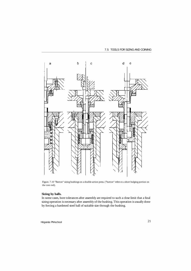
Core rod with a bulge. Fig. 7.10 shows another approach to the sizing of bores. The operating cycle can be commented as follows:
A) The bushing lies a the entrance of the die and is supported by a spring-loaded lower punch.B) The relieved end of the core rod passes through the bushing, and the upper punch forces the bushing into the die. At this point, the bushing is compressed to its final length. The core rod end is now guided in the lower punch.C) The core rod has a very short bulge which does the actual sizing. This bulge is now forced through the bushing to size the bore.D) The core rod moves upwards, re-sizing the bore while still guided in the lower punch.E) The upper punch withdraws, and the bushing is ejected by the lower punch.
The important points in this design are: • The outside diameter and the length of the bushing are fully sized before the bore.• The core rod is guided in the lower punch. An unguided core rod tends to wander,
particularly when sizing long bushings. The guiding of the core rod end in the lower punch prevents this.
• The sizing is done by a short bulge on the core rod The usual rule in sizing is that the working part of the core rod should be longer than the bushing to ensure a straight hole and control all the bore surface. By this alternative method, straightness is achieved by guiding the core rod end, and the sizing bulge is passed right through the bore. This action requires less load than the normal core rod, but as the sizing bulge passes, the bore will tend to close slightly.
• As the core rod is withdrawn, the sizing action is repeated in an upward direction. This second sizing does less work than the downward sizing and gives a fine finish to the bore of the bushing.
7.5 TOOLS FOR SIZING AND COINING
21Höganäs PM-school
Sizing by balls. In some cases, bore tolerances after assembly are required to such a close limit that a final sizing operation is necessary after assembly of the bushing. This operation is usually done by forcing a hardened steel ball of suitable size through the bushing.
Figure. 7.10 ”Button“ sizing bushings on a double-action press. (”button“ refers to a short bulging portion on the core rod).

7. RE-COMPACTING, COINING AND SIZING
22
Consistently close tolerances as small as 5 µm to 7 µm are claimed for this method if the limitations of the process as given below are understood and accepted:
• The normal sizing operation on the bushing must be done to the closest practical tolerance.
• The bushing, after assembly, must leave the absolute minimum for correction by ball sizing. The aim should be to have the upper limit of the assembled bushings falling within the required final tolerance and only the variation in bushing diameter after assembly should fall below the required lower limit. Fig. 7.11 shows this schematically.
• The bushing must not project from the housing, and the housing must be rigid enough to give adequate support to the bushing during the operation.
The use of a ball for sizing a bushing has certain advantages and limitations. The spherical form offers an infinite number of new faces to the bore, and therefore, wears very little and gives consistent results. Standard steel balls can be reduced to any required size by immersion in a suitable acid solution. Replacement of the balls is much less expensive than replacement of a worn core rod.
On the other hand, a ball can only follow the path of least resistance whereas a cylindrical core rod tends to make a straight hole. For this reason, the increase in bore diameter cannot be more than 10 µm to 20 µm, and the process is generally limited to short holes.
Figure. 7.11 Tolerance diagram for ball-sizing bushings after assembly.

7.5 TOOLS FOR SIZING AND COINING
23Höganäs PM-school
As shown in Fig. 7.12, the equipment for ball sizing can be very simple consisting of a hand press, a location plate for the housing, an undersize core rod with the end ground flat and a supply of balls. The core rod is attached to the press ram, the housing located by hand, and a ball place in the mouth of the bushing. The ram is brought down and forces the ball through the bushing.
The simplicity of the operation often leads to its use in other ways, e.g. in the correcting of short thick components which have been rejected after sizing for undersize bores, due perhaps to a worn core rod. On the other hand, where ball sizing is required as a necessary operation for large quantity production, semi-automatic equipment can be designed to perform the operation at a high rate.
Fig. 7.13a shows a design for use with a normal crankshaft press fitted with a knockout. A rotary feed table brings the components into position below the core rod. The balls are arranged to re-circulate, being lifted up a tube by the knockout after each operation so that the top ball rolls down into a spring clip below the core rod ready for the next operation.
In the alternative design shown in Fig. 7.13b the balls are forced upward through the component which is lifted up slightly to rest below a seating above the rotary feed table. The balls re-circulate by gravity. The ram could be operated either mechanically or hydraulically. This scheme is well suited for use on a multiple station machine which presses-in the bushings, ball sizes the assembly and performs other operations.
Figure. 7.12 Simple ball-sizing for assembled bushings.

7. RE-COMPACTING, COINING AND SIZING
24
Fitting of bushings. Earlier in this chapter, we mentioned that tolerances on bushings were dependent upon the tolerances of the housing into which they were fitted. Bushings are always located on a shouldered mandrel when being assembled into a housing. As the shoulder forces the bushing into the housing, the mandrel helps to control the final size of the bore of the bushing. The size of the mandrel is dependent upon many factors including the bore of the bushing, wall thickness, interference with the housing.
Manufacturers of standard ranges of bushings usually specify correct mandrel sizes for each bushing. Sa a general guide, the mandrel is made 0,02% to 0,04% larger than the minimum tolerance of the bore.
As the bushing is pressed into the housing, the bushing bore contracts upon the mandrel. After assembly, the mandrel can be withdrawn without difficulty. This method of assembling bushings prevents the tendency to wrinkling which results from the reduction in the outside diameter during assembly.
a. b.
Figure. 7.13 Automatic ball-sizing, a) balls being fed and pushed from above, b) balls being fed and pushed from below.

7.5 TOOLS FOR SIZING AND COINING
25Höganäs PM-school
Spherical bushings. The sizing operation on a spherical bushing has some peculiarities which are worth examination.
• A spherical bushing must have a bore with good surface finish and narrow tolerance.• The spherical diameter must be held within close limits, and as the two spherical
surfaces must obviously be sized by opposed parts of the tooling, this means in practice a close tolerance on the height of the part.
• The bore of a spherical bushing after sintering tends to vary due the changing wall thickness.
• The spherical form of the bushing is naturally highly resistant to the sizing action, as a spherical form has the greatest resistance to pressure exerted evenly over its whole surface.
• In addition to sizing the bore and spherical form, the small flats left in pressing must be forced within the spherical form.
A simple tool for sizing spherical bushings is shown at Fig. 7.14. The bushing is located over the relieved end of a fixed core rod and rests upon the lower punch. The upper punch descents, pushing the spherical bushing into the die, then over the full diameter of the core rod until finally the spherical form is sized between the upper punch and the spherical portion of the die.
After the upper punch has been raised, the lower punch ejects the component to the die face.One fault in such design is that whereas the spherical form in the die blends smoothly with the cylindrical outer diameter, the spherical form in the upper punch cannot blend smoothly due to the sharp edge on the punch.
It is therefore, necessary in such a tool to double-size the bushing, inverting it after the first cycle, in order that both shoulders formed by the edges of the pressing punches should be properly re-formed. For this reason, such a tool design is only useful for small quantities.

7. RE-COMPACTING, COINING AND SIZING
26
Fig. 7.15, shows a tool, design in which the sizing of the pressing flats can be accomplished in one cycle. Here, the component is again located on the relieved end of a fixed core rod. The die in this design is spring-supported and has a shallow cavity exactly half the length of the finished part. The upper punch does not enter the die, but has a flat land surrounding the cavity. The upper punch cavity is the mirror image of the die cavity, each containing exactly half the outer form of the part. As the upper punch descends, it forces the component down the core rod into the die and, with the faces of upper punch and die slightly separated, the die also moves downward.
The component is carried over the full diameter of the core rod until it reaches its lower stop when final compression by the upper punch sizes the outer form of the part. As the upper punch withdraws, the die returns to its initial position, and the lower punch follows to eject the component.
Figure. 7.14 Simple ”turn-over“ sizing for spherical bushings.

7.5 TOOLS FOR SIZING AND COINING
27Höganäs PM-school
There are two possible sources of trouble in this design:
1. The core rod relief must be kept to a minimum to ensure that the component is properly located, as otherwise the edges formed on the bushing by the pressing punches will catch th e edge of the upper punch cavity and damage the bushing. A small radius or chamfer on the edge of the upper punch cavity helps to avoid this trouble.
2. As the faces of upper punch and die are in contact at the final sizing stage, these faces must be kept clean. If the part has been produced to long in pressing, there will be a tendency for material to be extruded between punch and die faces just before these faces meet. This will result in oversize parts with sharp burr and will overload both press and tools.
Figure. 7.15 Complete sizing for spherical bushings.

7. RE-COMPACTING, COINING AND SIZING
28
The central cylindrical portion on the outside of the spherical bushing is usually specified only because it is essential when pressing the green compact. The tolerance on the cylindrical portion is therefore not important, and in fact, the customer would probably prefer the bushing entirely spherical.
In sizing, as the upper punch cavity gradually closes up on the die cavity, the outer form of the bushing is changed as shown at Fig. 7.16 a and b.
Fig. 7.16a shows the sintered bushing holding the upper punch and die apart as it is moved downward. Only the small shoulders touch the upper punch and die at this stage.
Fig. 7.16b shows the bushing at the final compression stage. The small shoulders have been forced into the spherical form, but small depressions are always visible where the shoulders have been reformed (at X in the figure).
7.5.3 Profiled Parts with Holes
A typical example of a profiled part with hole is the cam shown in Fig. 7.17a. This type of part is particularly suited to the powder metal technique. The cam profile and the keyed hole will almost certainly have tolerances requiring sizing, and coining in such a case can improve the wear resistance of the material.
The tool design for this part is similar to Fig. 7.5 with the addition of a relieved core srewed into the central hole of the die bolster. The core rod profile must be positioned to suit the loading position of the component.
This is often arranged by the use of a thin adjusting washer beneath the core rod shoulder. The problem of offset loading appears again, as it did in Fig. 7.5, and in this case, the core rod presents an additional problem.
Figure. 7.16 Detail of sizing action on spherical bushings.

7.5 TOOLS FOR SIZING AND COINING
29Höganäs PM-school
It would obviously be preferable to set the core rod on the ram centerline, both to simplify toolmaking and to avoid an offset load on the core rod. In the example shown, the latter factor is probably more important than the offset loading of the ram, and the core rod is therefor placed centrally. The combination of a profiled outer form with a profiled hole raises the question of correct alignment in the finished part. Under the heading Eccentricity in the advice upon bushings we pointed out the necessity for avoiding errors at the pressing stage.
This applies equally to alignment of external and internal profiles. Sizing and coining tools cannot be expected to correct errors in alignment due to faults in pressing, and attempts to reset the key in correct alignment with the cam profile will certainly end in a broken core rod.
Alternatively, an upper core rod can be used, as shown at Fig. 7.7, if a suitable press is available, but it should be remembered that with an upper core rod, the bore should be sintered oversize. With a thick-walled component it is more difficult to make the oversize bore contract to the core rod.
Fig. 7.17b shows another profiled part having, in this case, two holes. Except that the sizing of the holes will require twin core rods set on a single base, the general design picture is unchanged. The problem here is another aspect of the alignment – in this case, variations in the center distance of the two holes. Unless a careful check is maintained during the pressing and sintering operations, the parts presented for sizing will have excessive variations in hole centers.
The holes are small, and the sizing core rods correspondingly weak, so that even if the core rods do not break, being sufficiently flexible, the resulting holes will tend to be out of parallel and bell-mouthed. For these reasons, variations in hole centers, after sintering must be strictly limited.
Figure. 7.17 Typical profiled components with holes.

7. RE-COMPACTING, COINING AND SIZING
30
In Fig. 7.10 we gave an example in which the bore of a bushing was double-sized by a short bulge on the core rod. An example of this method applied to an external profile is the tooling developed by engineers of the Ford Motor Co. in the USA for sizing oil pump gears and similar forms.
Manufacture of a solid tungsten carbide die of 75 mm length and containing an accurate gear profile presented such problems that it was decided to experiment with a short die section and double-size the gears by passing them through the short die and then re-passing them upwards before ejection. This method has since been used by other companies and a typical design is shown at Fig. 7.18.
The die is made up of three sections, a location plate, (a) into which the sintered gear is placed (by hand or by an automatic feeding device), a tungsten carbide ring, (b) only 12 mm thick, and a lower die, (c) made of tool steel. The core rod is attached below the die.
The sintered gear is produced slightly oversize on both bore and outside form and rests on the rounded-off lip of the tungsten carbide ring. The upper punch forces the gear down through the tungsten carbide ring, closing the bore on to the core rod. The lower section of the die is made larger than the tungsten carbide ring by an amount less than its normal expansion, and as the gear passes into the lower die, it expands slightly. During the entire sizing operation, there is no compression of the gear faces between upper and lower punches, as the end faces of the gear are ground to close tolerances in a later operation. The dimensions must be carefully considered on such design, to prevent lead or spiral on the gears, as result of the short die.

7.5 TOOLS FOR SIZING AND COINING
31Höganäs PM-school
7.5.4 Parts with External Flanges
The typical part in this family is the flanged bushing, but there are also many other types of parts with flanges, as e.g. flanged connections. In a normal flanged bushing, the narrowest tolerances are required on the inner diameter and on the body outer diameter. It is, however, necessary to control the flange outer diameter and flange faces also, to avoid variations in the final size of the bore at the flanged end.
Figure. 7.18 ”Ring“ sizing for profiled components like e.g. oil pump gears; a = location plate, b = profiled sizing ring of tungsten carbide, c = tool steel die.
a
b
c

7. RE-COMPACTING, COINING AND SIZING
32
Fig. 7.19 shows a tool design in which the part is located over relieved end of a core rod secured to the base of the tool. As the press cycle begins, the lower punch drops away and the part rests between the core rod and the smaller diameter of the die.
The upper punch completes the movement of the part on to the die shoulder. The die, which has a limited downward motion, is supported on wedges, rubber pads, or a pneumatic cushion. The die support should be adjustable as it must be strong enough to resist the force of the bushing as it is pushed into the die. If the support pressure is too weak, the die will move downwards before the bushing’s outer diameter has been sized, and both external and internal sizing will take place simultaneously.
The continuing motion of the upper punch carries the the part downwards, over the final diameter of the core rod, and sizes the length of the part against the lower punch.
Stops beneath the die control the flange thickness also. After the upper punch has withdrawn, the part is ejected by the lower punch, carrying the die upwards to its original position.
In all cases where sizing is required on a diameter which finishes below a shoulder, a radius is essential at the junction of shoulder and sized diameter, as the die shoulder must be rounded-off to perform its function of swaging the part to size. The proposals made in connection with Fig. 7.3, regarding the swaging radius, can be applied here.
Figure. 7.19 Sizing flanged bushings in a single-action press.

7.5 TOOLS FOR SIZING AND COINING
33Höganäs PM-school
Fig. 7.20 shows an alternative design for use with a double action press. Here, the die does not move, and the progressive sizing action is obtained by the separate motions of the upper punch, attached to the blank holder, and the core rod, attached to th main ram.
To overcome the difficulty of locating the bushing, a dummy core rod is used which projects above the die face. This dummy core rod is spring-supported and is pushed downwards by the upper core rod as it descends.
The relative motion of upper punch and upper core rod can be arranged as shown in Fig. 7.7, where the bushing is contracted on to the core rod, or as in Fig. 7.8, where the core rod passes through the bushing after the outer diameter has been sized.
Fig. 7.21 shows how the proportions of a part can affect the tool design. Here, the long flange portion can be located by an outer location plate, leaving enough of the part projecting for the operator (or gripping device) to locate and remove it without difficulty. The dummy coe rod shown in Fig. 7.20 is unnecessary.
Figure. 7.20 Sizing flanged bushings in a double-action

7. RE-COMPACTING, COINING AND SIZING
34
The coining of shouldered parts presents another problem to the tool designer. Many coining operations require a reduction in volume by 10% or more. As the face area of the part is reduced very little, almost all the reduction in volume is achieved by reduction in length of the part. A 10% reduction in the flanged bushing shown in Fig. 7.19 would mean a reduction in the length below the flange of 1,5 mm.
If the tool is designed with a fixed die as in Fig. 7.20, the end of the bushing will meet the lower punch while the flange is still 1,5 mm above the die shoulder.
Any material moved by the swaging action of the die shoulder will tend to build up a wave beneath the flange of the bushing. The final downward movement of the bushing flange as it is compressed to correct length and density, tends to force this wave of material outwards and form a separate layer in the corner of the flange.
Figure. 7.21 Sizing bushings with thick flanges.

7.5 TOOLS FOR SIZING AND COINING
35Höganäs PM-school
In practice, where circumstances permit, the sintered part is usually made small enough to go easily inside the die shoulder, and thus no swaging action takes place. Even with this precaution, it is advisable, to avoid cracking on the bushing shoulder, to use a floating die design if the length beneath the shoulder is more than 6 or 7 mm.
7.5.5 Parts with Internal Flanges
The typical part in this family is the piston. Fig. 7.22 shows a simple design for sizing surfaces of a piston.
The part is placed within a location plate and rests upon the lower punch in its loading position. A shouldered core rod is rigidly secured below the die. As the upper punch descends, it first forces the piston skirt into the die, and then over the core rod.
If the proportions of the part permit, the length of the core rod tip, between the relieved portion and the core rod shoulder, should be longer than the skirt of the piston.
Figure. 7.22 Complete sizing of piston.

7. RE-COMPACTING, COINING AND SIZING
36
If this can be arranged, then the small bore of the piston will be sized before the skirt. Otherwise, the two bores are sized simultaneously. The part is ejected to the die face by the lower punch.
Many small pistons, used in automobile shock absorbers and for other purposes, have circular ribs on both faces of the piston head. Where these ribs have to be sized, it is sometimes more convenient to simplify the sizing operation by center-less grinding the outer diameter of the piston in a subsequent operation.
The simple tool shown in Fig. 7.23 is then quite satisfactory, and the job can frequently be done in a hand press. The part is placed head downwards in a shallow die plate, and the core rod, attached to the ram, descends to size the small bore and set the form of the ribs. As this action usually causes the part to grip the core rod, a simple stripper plate, attached to the die table, surrounds the core rod, and the part is freed as the core rod retracts through the stripper plate.
Fig. 7.24 shows a design suitable for a double-action press, where complete sizing is required on a piston. The part is placed within the location plate, resting upon the lower punch. The core rod is attached to the ram, and the upper punch to the blank holder.
Core rod and upper punch descend together, the punch forcing the part down the die to its final position. As the upper punch slows, the core rod speed is maintained, and the core rod sizes the small bore and large bore before finally sizing the ribs on the piston head. The core rod is withdrawn before the upper punch, and the lower punch then ejects the piston to the die face.
Figure. 7.23 Sizing piston faces and bore.

7.5 TOOLS FOR SIZING AND COINING
37Höganäs PM-school
There are numerous cases where a part is required with two internal steps, and profiled internal forms are not uncommon. Fig. 7.25 a shows an example of this type of part. The various problems and possibilities, connected with a profiled part like this, offer several alternative sizing tool designs.
Considering this stage by stage, the first point to be decided is the method of location. An external location will not prevent misalignment of the internal splines. Therefore, the part must be located on the core rod. An upper core rod cannot be used for location, so we start with a core rod within the die.
If we begin with the design shown in Fig. 7.25 b, we have a lower punch supporting the skirt of the part, and a core rod having three diameters within the part. This core rod is raised upon a spring to the ejecting position, and is forced down upon a stop by the action of the upper punch. The profiled portion of the core rod must project above the face of the lower punch after ejection to provide location for the part. 1,5 mm is practical minimum for this location height.
Figure. 7.24 Sizing pistons in a double-action press.

7. RE-COMPACTING, COINING AND SIZING
38
Two factors are immediately evident. First, the sintered part must be large enough to fit freely over the core rod. This is
often necessary and can be convenient if the part has been made oversize on the outer diameter and length dimensions, so that sufficient material is moved in sizing to close the part on to the core rod.
Second, the part after ejection is not free of the core rod. It is probable that the skirt of this part will, in fact, be free (i.e. not tightly fitting on the core rod), as the work done in sizing will have given the part an internal stress which will cause it to expand slightly upon leaving the die.
Figure. 7.25 Location of pistons with internal profiles. Figure. 7.26 Sizing pistons using upper core rod.
7-25 7-26
7.5 TOOLS FOR SIZING AND COINING
39Höganäs PM-school
This same effect can also tend to free the smaller bore of the part, but as the diameter here is only 50% of the larger bore, the expansion of the part will be correspondingly reduced. We are speaking now of very small dimensional changes. 10 to 20 µm might be anticipated on the skirt in this instance.
If the expansion on the smaller bore is 50% of this, it will be appreciable that very small variations can make the difference between a part which lifts easily and one which resists all attempts to move it.
For example, variations in sintered diameter of the small projecting boss on the upper face of the part could easily upset the anticipated expansion of the smaller bore. Another factor which can affect the removal of the part is that, in some cases, the stress within the part can actually provoce a tendency for the smaller bore to shrink as i comes off the core rod, even though the outside diameter of the part expands. For this reason, the tool might not work well, and one possible answer to the problem is shown at Fig. 7.25c.
As we are discussing a hypothetical part, portions have been assumed which demonstrate the typical problems. If, however, we have a part with a longer skirt relative to the thickness of the head, the problem of freeing the small bore from the core becomes simpler. The core rod tip can now be relieved as shown, and the part is easily located and removed. If the proportions of the part do not permit the above solution, the design shown at Fig. 7.26 presents another approach.
The major difficulty has been the freeing of the part from the smallest portion of the core rod, so this portion is now attached to the upper punch. The other internal forms are located on the spring-supported punch fitting within the lower punch. The part is still located upon the profile form, and the small bore of the part must be large enough to permit the descending core rod to fit easily inside it. The upper punch then forces the part into the die, completes the sizing, and upon withdrawal allows the part to be ejected and removed without difficulty.
Although the upper core rod and punch size only a small portion of the total vertical surface of the part, it is still possible that these portions of the part and the amount of work done in sizing might cause the part to grip the core and be drawn out of the die.
If a double acting press is available, the core rod and upper punch can be operated as in Fig. 7.21. alternatively, the design shown at Fig. 7.27 can be used. In this design, the smallest bore is sized by a fixed core rod fitting within the spring-supported lower punch.
The fixed lower core rod can be relieved, giving the double advantage that the smallest bore of the part can, if desired, be small after sintering, and the sizing action can be arranged progressively if the core rod relief is positioned correctly.
On the other hand, the design shown in Fig. 7.27 has one disadvantage. In this case, an additional moving part is required.

7. RE-COMPACTING, COINING AND SIZING
40
Any moving part must have sufficient clearance for satisfactory operation and, although each clearance may be only 12 to 20 µm, every additional moving part means a possible increase in eccentricity of the part.
From the forgoing examination of the design problems for various types of parts, it should be clear that tool designs are very much dependent upon the type of press available for sizing. In all that has been said it has been assumed that the presses operate upon a cycle normal for crank presses.
As the normal press completes its cycle with the ram at Top Dead Center, it follows that the ejection punch will stop at its highest point, level with the die face. In some cases, however, it can be arranged that the press stops some way beyond Top Dead Center, or the ejection mechanism can be offset in such a manner that the ejection punch comes to die face level, thus freeing the part, and then withdraws slightly before
Figure. 7.27 Sizing profiled pistons using lower core rod.

7.5 TOOLS FOR SIZING AND COINING
41Höganäs PM-school
coming to rest. The part will remain on the die face, due to its slight expansion on leaving the die. An example of such a case is shown at Fig. 7.28. The part is similar in type to that in Fig. 7.25a but here, the body of the part is much more solid and would probably not free itself from the core rod unless completely ejected.
If the motion of the ejection punch can be arranged so that it frees the part entirely from the core rod, and then withdraws sufficiently to permit location of the next part on the core rod, the operation becomes considerably simpler.
7.5.6 Other Complex Parts
Types of parts of more complex shape than those treated in the preceding paragraphs have special problems in pressing, particularly with ejection type tooling, but if such complex parts can be satisfactorily pressed, sizing and coining is usually less difficult. In practice, tooling designs for sizing and coining such parts are combinations based upon the designs already examined.
Figure. 7.28 Thick-walled component with internal profile.

7. RE-COMPACTING, COINING AND SIZING
42
References
[7-1] Data according to G. Bockstiegel, Archiv f.d. Eisenhüttenwesen 28, 3, 1957 pp. 167-177.