reactance calculations tf3080ch3
TRANSCRIPT
7/30/2019 Reactance Calculations Tf3080ch3
http://slidepdf.com/reader/full/reactance-calculations-tf3080ch3 1/31
87
3. REACTANCE CALCULATIONS
Summary Leakage reactances are calculated for transformers havingup to six separate windings per leg but with 2 or 3 terminals per phase.These calculations may be applied to single phase units or to one phase
of a 3 phase unit. Windings may be connected in series or auto-connected.In addition, tap windings or series taps within a winding may beidentified. Terminal-terminal and positive/negative sequence leakagereactances are calculated, as well as the T-equivalent circuit modelleakage reactances for 3 terminal transformers. Expressions for per-unitquantities are also given. When taps are present within a winding or asseparate windings, calculations are performed for the all in, all out, andcenter or neutral position and for all combinations if more than one
type of tap is present. The calculations are based on a 2 winding reactanceformula which assumes that the windings are uniform along their length,with a correction for end fringing flux. This has been found to be veryaccurate for most purposes but, if greater accuracy is desired, a bettertwo winding reactance calculation could be substituted without changingmost of the formulas presented here.
3.1 INTRODUCTIONThe reactance calculations performed here are on a per phase basis sothey would apply to a single phase unit or to one phase of a three phasetransformer. The phase can have up to six windings, interconnected insuch a way that only 2 or 3 terminals (external or buried) result. Thusauto-transformers, with or without tertiary, are included as well astransformers with tap windings. it should be noted that these reactances
are positive or negative sequence reactances. Zero sequence reactancesare somewhat sensitive to the three phase connection and to whether thetransformer is core-form or shell-form, but this does not appear to betrue for the positive/negative sequence reactances. Thus, in the followingdiscussion, we will be dealing with a single phase system which may ormay not be part of a 3 phase system.
It is usually desirable to design some reactance into a transformer inorder to limit any fault current. In addition, these reactances determine
© 2002 by CRC Press
7/30/2019 Reactance Calculations Tf3080ch3
http://slidepdf.com/reader/full/reactance-calculations-tf3080ch3 2/31
REACTANCE CALCULATIONS88
the voltage regulation of the unit. Hence it is desirable at the designstage to be able to calculate these reactances based on the geometry of the coils and core and the nature of the (single phase) windinginterconnections.
We begin by discussing ideal transformers, i.e. having no reactanceor resistance, since real transformers are usually described by addinglumped resistance and reactance circuit elements to a model of an idealtransformer. The following references have been used in this chapter:[MIT43], [Lyo37], [Blu51], [Wes64].
3.2 IDEAL TRANSFORMERS
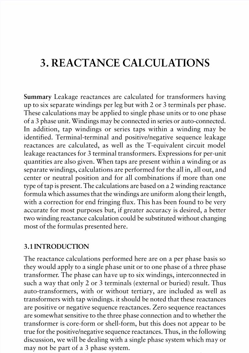
In an ideal 2 winding transformer as depicted in Fig. 3.1, the entire fluxφ links both windings so that, by Faraday’s law, the induced emf’s aregiven by
(3.1)
Hence
(3.2)
We use the convention that the current is positive when entering thepositive terminal and that the fluxes generated by these positive currents
add.
Figure 3.1 Ideal 2 winding transformer
© 2002 by CRC Press
7/30/2019 Reactance Calculations Tf3080ch3
http://slidepdf.com/reader/full/reactance-calculations-tf3080ch3 3/31
89REACTANCE CALCULATIONS
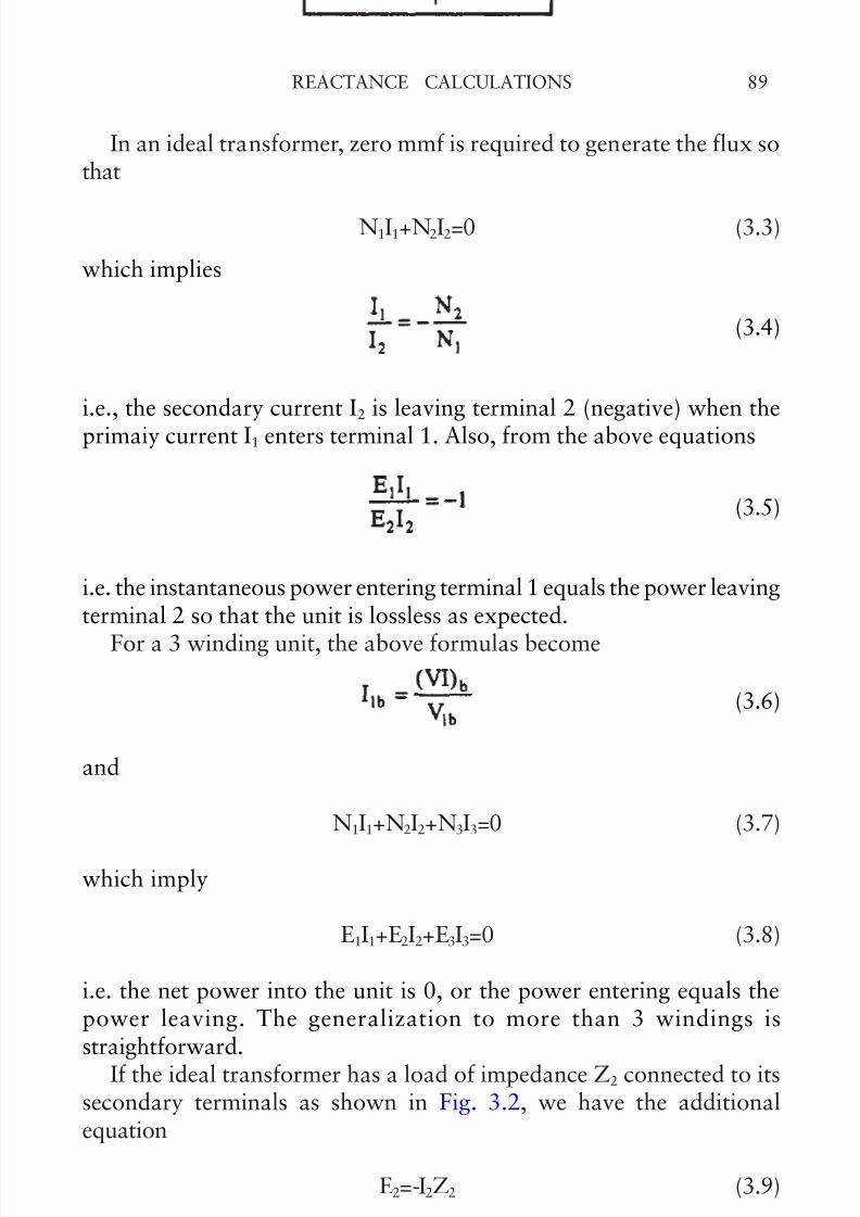
In an ideal transformer, zero mmf is required to generate the flux sothat
N1I1+N2I2=0 (3.3)
which implies
(3.4)
i.e., the secondary current I2 is leaving terminal 2 (negative) when theprimaiy current I1 enters terminal 1. Also, from the above equations
(3.5)
i.e. the instantaneous power entering terminal 1 equals the power leavingterminal 2 so that the unit is lossless as expected.
For a 3 winding unit, the above formulas become
(3.6)
and
N1I1+N2I2+N3I3=0 (3.7)
which imply
E1I1+E2I2+E3I3=0 (3.8)
i.e. the net power into the unit is 0, or the power entering equals thepower leaving. The generalization to more than 3 windings isstraightforward.
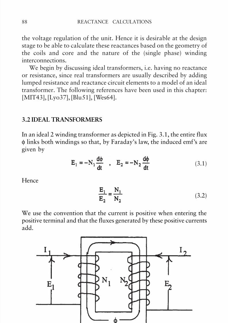
If the ideal transformer has a load of impedance Z2 connected to itssecondary terminals as shown in Fig. 3.2, we have the additionalequation
E2=-I2Z2 (3.9)
where -I2 is the load current, usually denoted IL.
© 2002 by CRC Press
7/30/2019 Reactance Calculations Tf3080ch3
http://slidepdf.com/reader/full/reactance-calculations-tf3080ch3 4/31
REACTANCE CALCULATIONS90
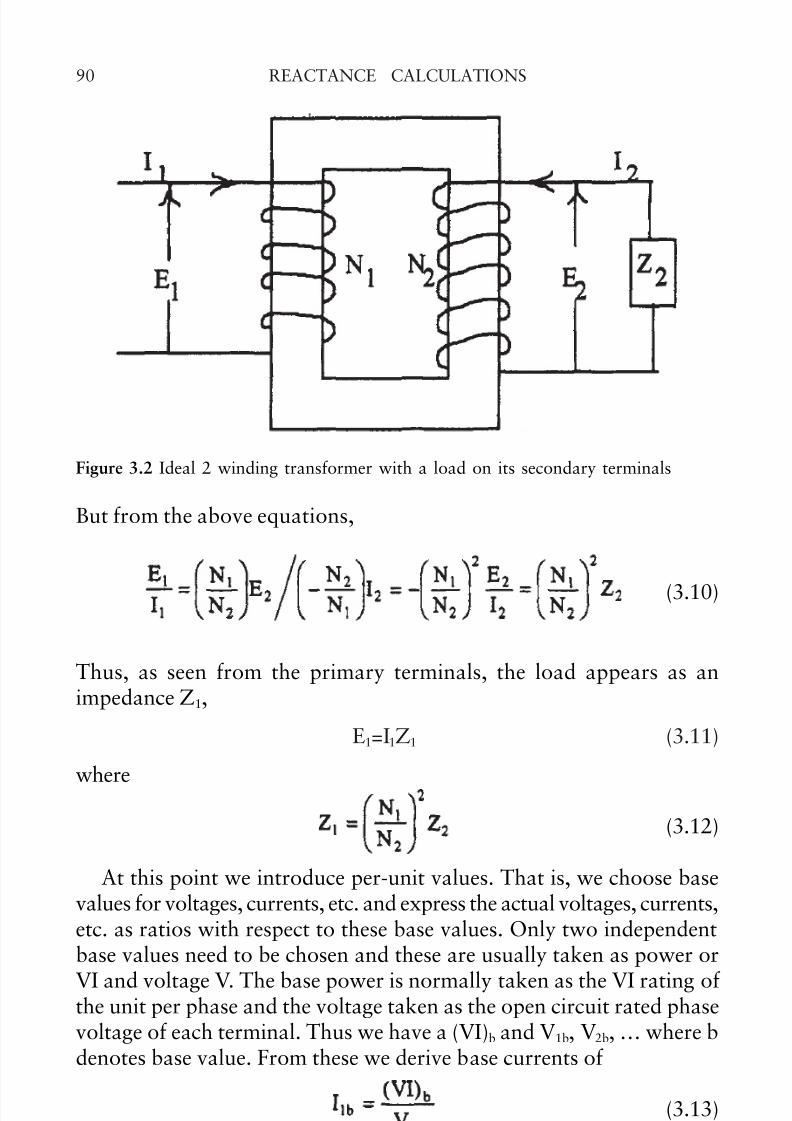
But from the above equations,
(3.10)
Thus, as seen from the primary terminals, the load appears as animpedance Z1,
E1=I1Z1 (3.11)
where
(3.12)
At this point we introduce per-unit values. That is, we choose basevalues for voltages, currents, etc. and express the actual voltages, currents,etc. as ratios with respect to these base values. Only two independentbase values need to be chosen and these are usually taken as power or
VI and voltage V. The base power is normally taken as the VI rating of the unit per phase and the voltage taken as the open circuit rated phasevoltage of each terminal. Thus we have a (VI)b and V1b, V2b, … where bdenotes base value. From these we derive base currents of
(3.13)
and base impedances
Figure 3.2 Ideal 2 winding transformer with a load on its secondary terminals
© 2002 by CRC Press
7/30/2019 Reactance Calculations Tf3080ch3
http://slidepdf.com/reader/full/reactance-calculations-tf3080ch3 5/31
91REACTANCE CALCULATIONS
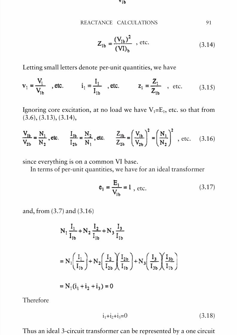
(3.14)
Letting small letters denote per-unit quantities, we have
(3.15)
Ignoring core excitation, at no load we have V1=E1, etc. so that from
(3.6), (3.13), (3.14),
(3.16)
since everything is on a common VI base.In terms of per-unit quantities, we have for an ideal transformer
(3.17)
and, from (3.7) and (3.16)
Therefore
i1+i2+i3=0 (3.18)
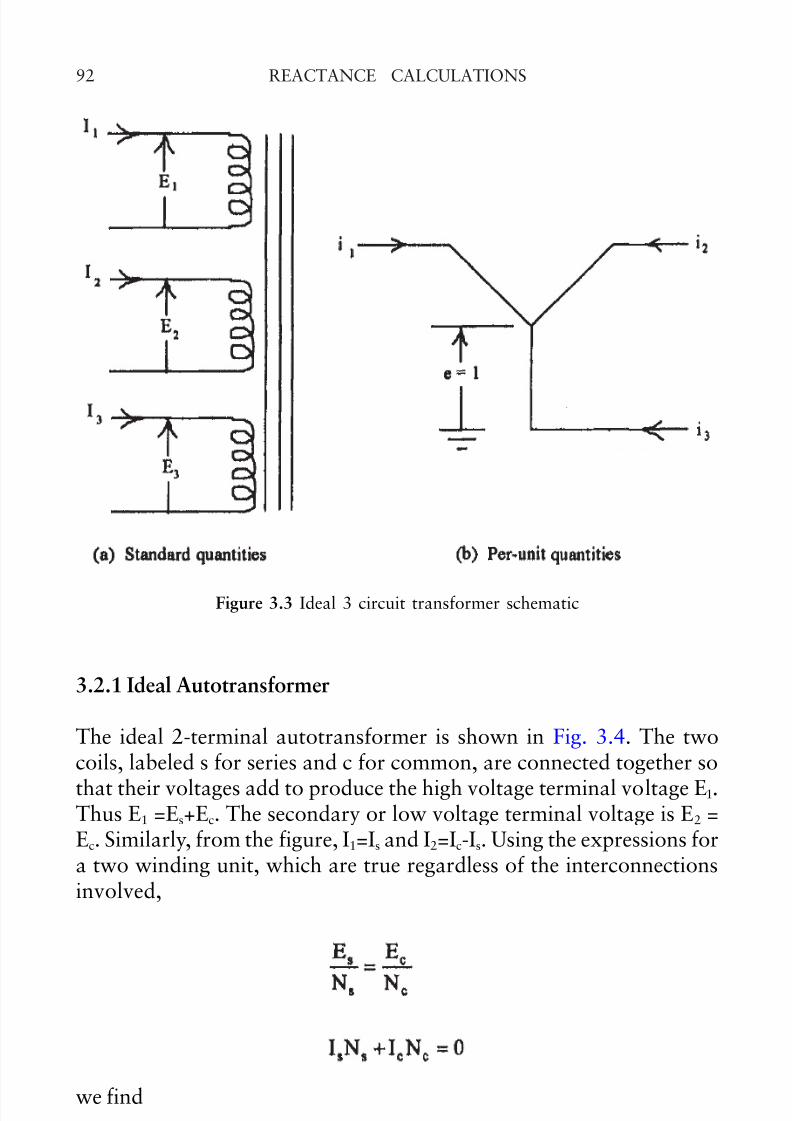
Thus an ideal 3-circuit transformer can be represented by a one circuitdescription as shown in Fig. 3.3, if per-unit values are used. This alsoholds if more than 3 circuits are present.
, etc.
etc.
, etc.
, etc.
© 2002 by CRC Press
7/30/2019 Reactance Calculations Tf3080ch3
http://slidepdf.com/reader/full/reactance-calculations-tf3080ch3 6/31
REACTANCE CALCULATIONS92
3.2.1 Ideal Autotransformer
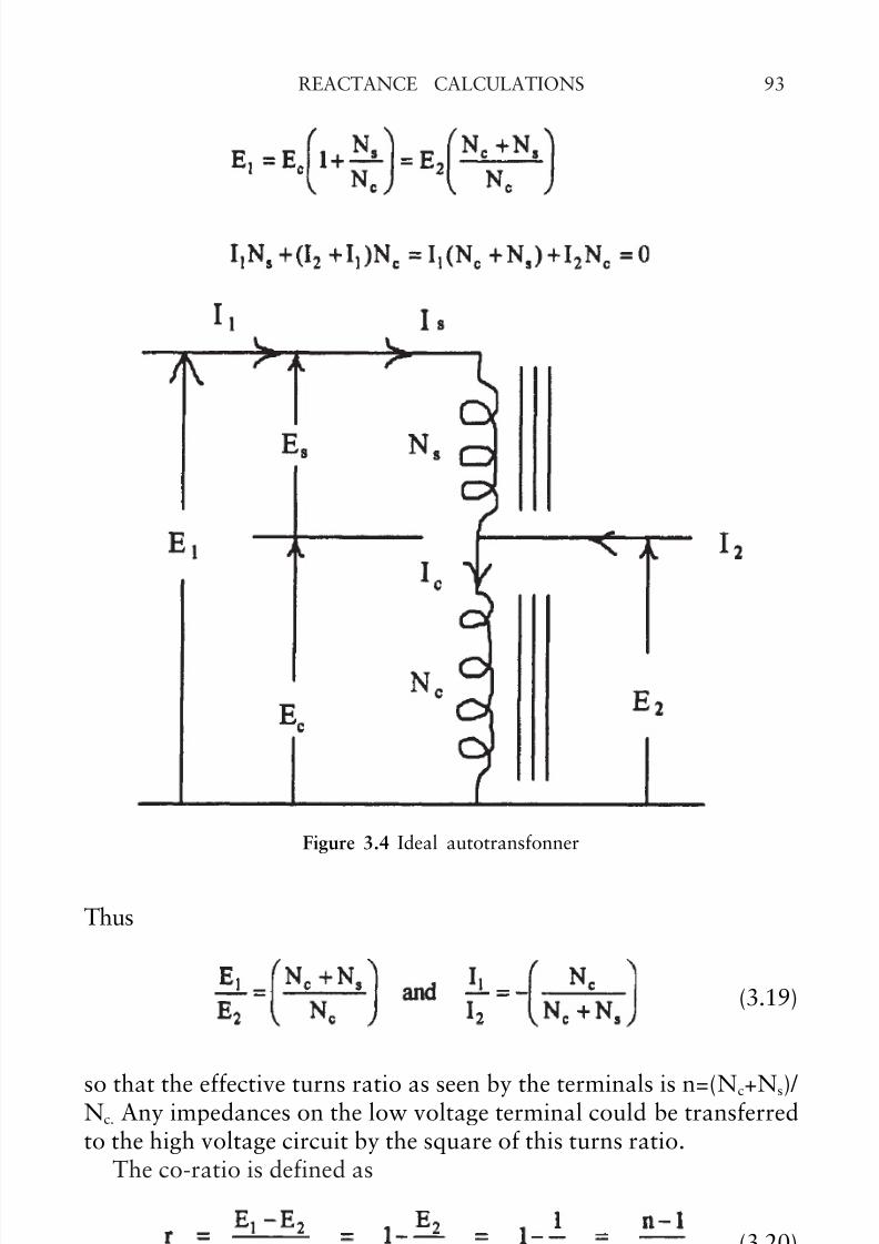
The ideal 2-terminal autotransformer is shown in Fig. 3.4. The twocoils, labeled s for series and c for common, are connected together so
that their voltages add to produce the high voltage terminal voltage E1.
Thus E1 =Es+Ec. The secondary or low voltage terminal voltage is E2 =Ec. Similarly, from the figure, I1=Is and I2=Ic-Is. Using the expressions fora two winding unit, which are true regardless of the interconnectionsinvolved,
Figure 3.3 Ideal 3 circuit transformer schematic
we find
© 2002 by CRC Press
7/30/2019 Reactance Calculations Tf3080ch3
http://slidepdf.com/reader/full/reactance-calculations-tf3080ch3 7/31
93REACTANCE CALCULATIONS
Thus
(3.19)
so that the effective turns ratio as seen by the terminals is n=(Nc+Ns)/ Nc. Any impedances on the low voltage terminal could be transferredto the high voltage circuit by the square of this turns ratio.
The co-ratio is defined as
(3.20)
Figure 3.4 Ideal autotransfonner
© 2002 by CRC Press
7/30/2019 Reactance Calculations Tf3080ch3
http://slidepdf.com/reader/full/reactance-calculations-tf3080ch3 8/31
REACTANCE CALCULATIONS94
where r < 1. The terminal power rating of an autotransformer is E1I1 (=-E2I2) but the power rating of each coil is ESIS (=-EcIc). The ratio of thesepower ratings is
(3.21)
Thus, since r<1, the terminal rating is always greater that the single coilrating. Since the single coil rating is the same as the terminal rating of a conventional 2-winding transformer, this shows an important advantageof using the auto connection,
3.3 LEAKAGE IMPEDANCE FOR 2-WINDING TRANSFORMERS
In real transformers not all the flux links the windings. In addition,there are resistive losses in the windings as well as core losses. The
basic equations for the terminal voltages are now given by
(3.22)
wheres λ 1 is the flux linkages of coil 1 and R1 its resistance and similarlyfor coil 2. If we let
= the common flux linking all turns of both coils, which is mainly
core flux, we can write
(3.23)
The quantity is the leakage flux of coil i. It exists mainly inthe oil or air and conductor material but not in the core to any greatextent. Thus it exists in non-magnetic (or linear) materials and therefore
should depend linearly on the currents. Thus we can write very generally
or, assuming sinusoidal quantities,
© 2002 by CRC Press
7/30/2019 Reactance Calculations Tf3080ch3
http://slidepdf.com/reader/full/reactance-calculations-tf3080ch3 9/31
95REACTANCE CALCULATIONS
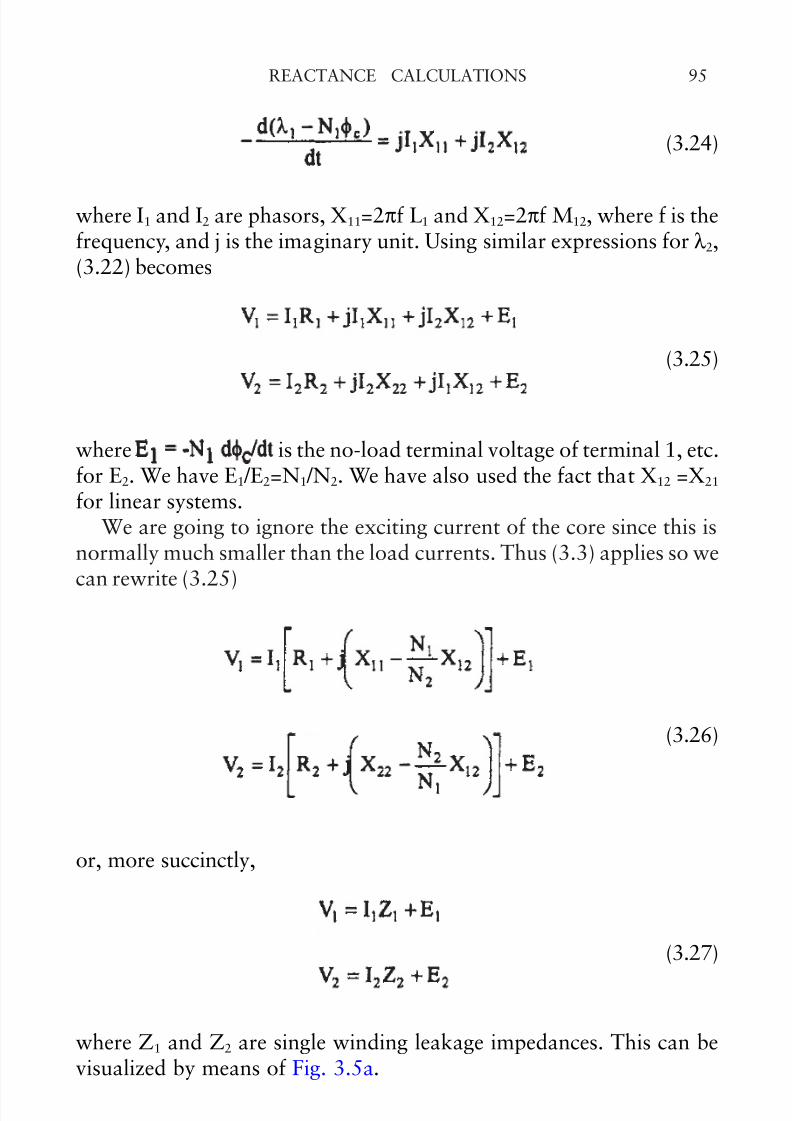
(3.24)
where I1 and I2 are phasors, X11=2πf L1 and X12=2πf M12, where f is thefrequency, and j is the imaginary unit. Using similar expressions for λ 2,(3.22) becomes
(3.25)
where is the no-load terminal voltage of terminal 1, etc.for E2. We have E1 /E2=N1 /N2. We have also used the fact that X12 =X21
for linear systems.We are going to ignore the exciting current of the core since this is
normally much smaller than the load currents. Thus (3.3) applies so we
can rewrite (3.25)
(3.26)
or, more succinctly,
(3.27)
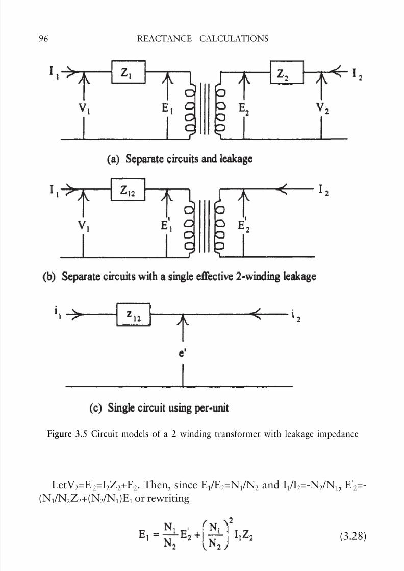
where Z1 and Z2 are single winding leakage impedances. This can bevisualized by means of Fig. 3.5a.
© 2002 by CRC Press
7/30/2019 Reactance Calculations Tf3080ch3
http://slidepdf.com/reader/full/reactance-calculations-tf3080ch3 10/31
REACTANCE CALCULATIONS96
LetV2=E'2=I2Z2+E2. Then, since E1 /E2=N1 /N2 and I1 /I2=-N2 /N1, E'
2=-
(N1 /N2Z2+(N2 /N1)E1 or rewriting
(3.28)
Substituting into (3.27), we get
Figure 3.5 Circuit models of a 2 winding transformer with leakage impedance
© 2002 by CRC Press
7/30/2019 Reactance Calculations Tf3080ch3
http://slidepdf.com/reader/full/reactance-calculations-tf3080ch3 11/31
97REACTANCE CALCULATIONS
(3.29)
We see that (3.29) can be expressed in terms of a single effectiveimpedance Z12=Z1+(N1 /N2)2 Z2,
(3.30)
where E21 /E22=N1 /N2. The circuit model for this is shown in Fig. 3.5b.Using per-unit values, the picture in Fig. 3.5c applies. Note that E
1 /E
2=E'1 /E’2=N1 /N2 but that E1≠E'1, E2≠E'2 except at no load.
Thus a two winding transformer is characterized by a single value of leakage impedance Z12 which has both resistive and reactivecomponents,
Z12= R12+ jX12
where
(3.31)
and
referred to the primary winding. We can obtain expressions for referringquantities to the secondary winding by interchanging 1 and 2 in theabove formulas. In large power transformers X12>>R12 so we are normallyconcerned with obtaining leakage reactances.
In terms of previously defined quantities,
© 2002 by CRC Press
7/30/2019 Reactance Calculations Tf3080ch3
http://slidepdf.com/reader/full/reactance-calculations-tf3080ch3 12/31
REACTANCE CALCULATIONS98
(3.32)
(Note that X12 in (3.32) is not the same as that in (3.31). We will usuallyuse the symbol Z12 when referring to leakage impedances and ignore the
resistive component so no confusion should arise.) Z12 will be calculatedby more direct methods later so (3.32) is rarely used.We should note that another method of obtaining the effective
2winding leakage impedance, which corresponds with how it ismeasured, is to short circuit terminal 2 and perform an impedancemeasurement using terminal 1. Thus
(3.33)
Using (3.27), this implies that E2 = -I2 Z2. But, using (3.2) and (3.3), weget E1=I1(N1 /N2)2 Z2. Substituting into the V1 equation of (3.27), we find
so that, from (3.33), we get Z12=Z1+(N1 /N2)2 Z2 as before.
3.3.1 Leakage Impedance for a 2-Winding utotransformer
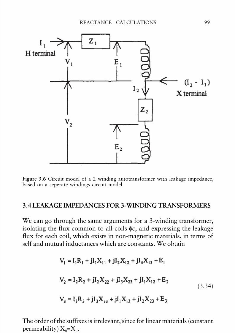
The circuit model for a 2-winging autotransformer can be constructedfrom separate windings as shown in Fig. 3.6. From the definition of leakage impedance (3.33), we measure the impedance at the H terminalwith the X terminal shorted. But this will yield the same leakageimpedance as that of an ordinary 2-winding transformer so that ZHX=Z12, i.e. the terminal leakage impedance of a two windingautotransformer is the same as that of a transformer with the samewindings but not auto-connected.
© 2002 by CRC Press
7/30/2019 Reactance Calculations Tf3080ch3
http://slidepdf.com/reader/full/reactance-calculations-tf3080ch3 13/31
99REACTANCE CALCULATIONS
3.4 LEAKAGE IMPEDANCES FOR 3-WINDING TRANSFORMERS
We can go through the same arguments for a 3-winding transformer,isolating the flux common to all coils φc, and expressing the leakageflux for each coil, which exists in non-magnetic materials, in terms of self and mutual inductances which are constants. We obtain
(3.34)
The order of the suffixes is irrelevant, since for linear materials (constantpermeability) Xij=Xji.
Using the same assumptions as before concerning the neglect of coreexcitation, equation (3.7), we substitute I3=-(N1 /N3) I1-(N2 /N3) I2 in the
Figure 3.6 Circuit model of a 2 winding autotransformer with leakage impedance,based on a seperate windings circuit model
© 2002 by CRC Press
7/30/2019 Reactance Calculations Tf3080ch3
http://slidepdf.com/reader/full/reactance-calculations-tf3080ch3 14/31
REACTANCE CALCULATIONS100
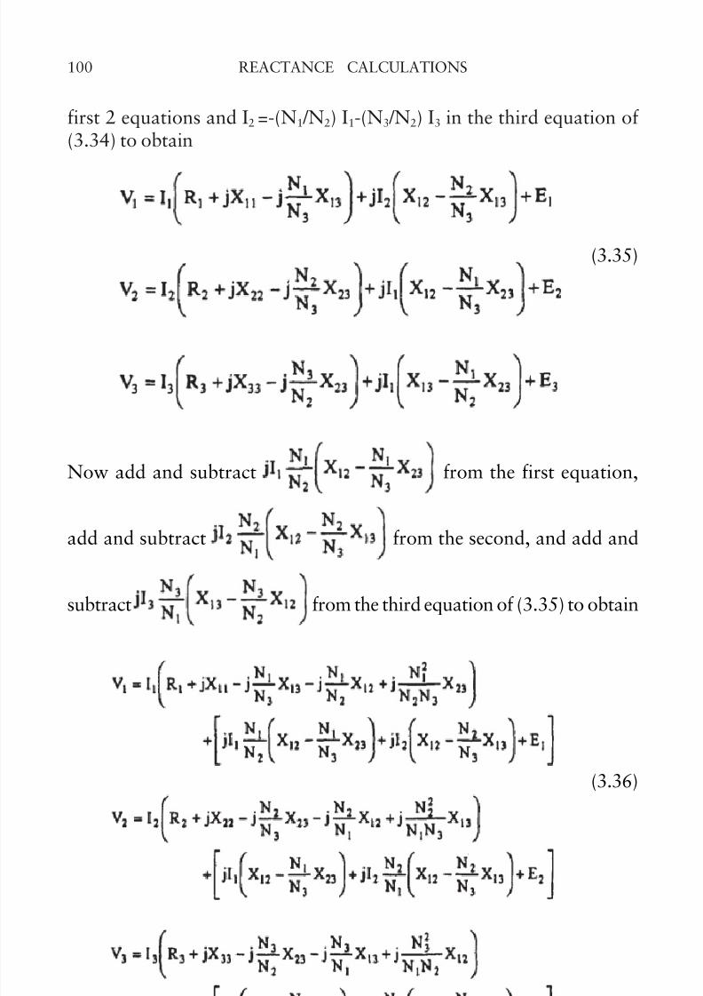
first 2 equations and I2 =-(N1 /N2) I1-(N3 /N2) I3 in the third equation of (3.34) to obtain
(3.35)
Now add and subtract from the first equation,
add and subtract from the second, and add and
subtract from the third equation of (3.35) to obtain
(3.36)
© 2002 by CRC Press
7/30/2019 Reactance Calculations Tf3080ch3
http://slidepdf.com/reader/full/reactance-calculations-tf3080ch3 15/31
101REACTANCE CALCULATIONS
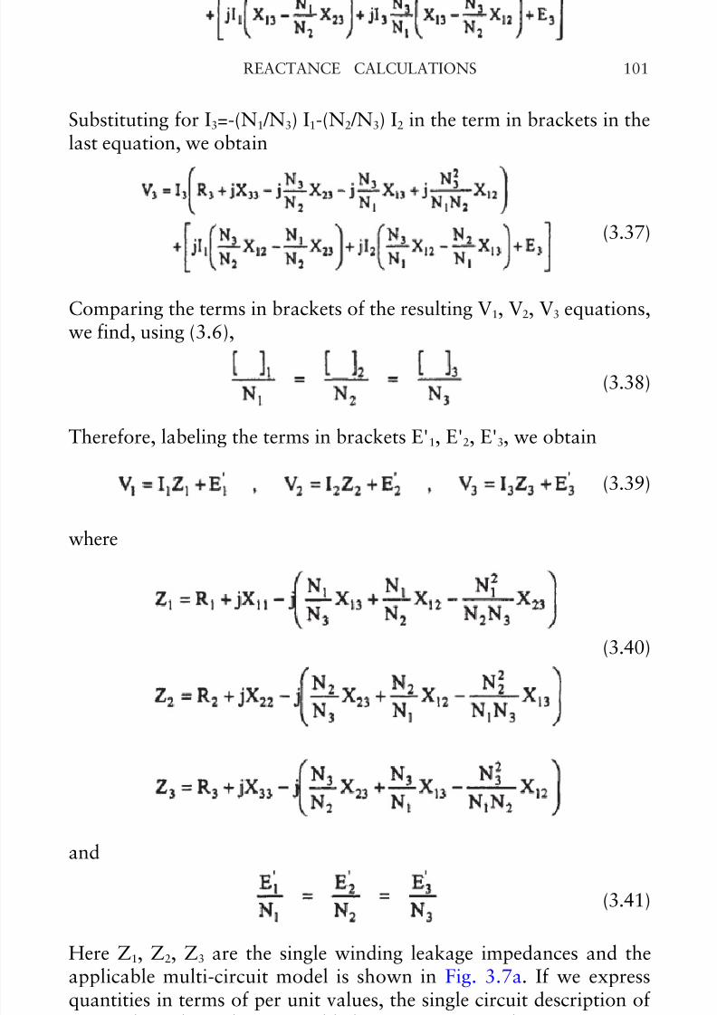
Substituting for I3=-(N1 /N3) I1-(N2 /N3) I2 in the term in brackets in thelast equation, we obtain
(3.37)
Comparing the terms in brackets of the resulting V1, V2, V3 equations,we find, using (3.6),
(3.38)
Therefore, labeling the terms in brackets E'1, E'2, E'3, we obtain
(3.39)
where
and
(3.41)
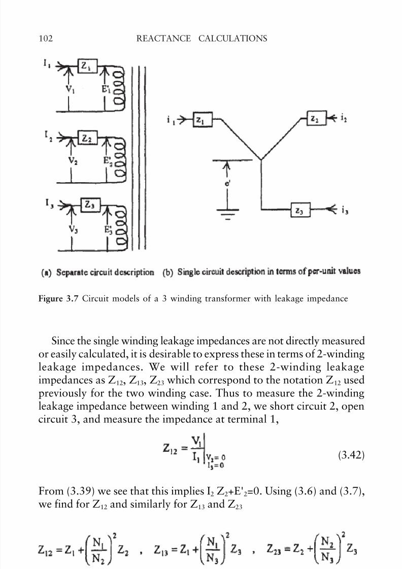
Here Z1, Z2, Z3 are the single winding leakage impedances and theapplicable multi-circuit model is shown in Fig. 3.7a. If we expressquantities in terms of per unit values, the single circuit description of Fig. 3.7b applies. This is possible because (3.41) implies e'1=e'2=e'3=e'and by equation (3.18). This figure should be compared with Fig. 3.3.
(3.40)
© 2002 by CRC Press
7/30/2019 Reactance Calculations Tf3080ch3
http://slidepdf.com/reader/full/reactance-calculations-tf3080ch3 16/31
REACTANCE CALCULATIONS102
Since the single winding leakage impedances are not directly measuredor easily calculated, it is desirable to express these in terms of 2-windingleakage impedances. We will refer to these 2-winding leakageimpedances as Z12, Z13, Z23 which correspond to the notation Z12 used
previously for the two winding case. Thus to measure the 2-windingleakage impedance between winding 1 and 2, we short circuit 2, opencircuit 3, and measure the impedance at terminal 1,
(3.42)
From (3.39) we see that this implies I2 Z2+E'2=0. Using (3.6) and (3.7),we find for Z12 and similarly for Z13 and Z23
Figure 3.7 Circuit models of a 3 winding transformer with leakage impedance
(3.43)
© 2002 by CRC Press
7/30/2019 Reactance Calculations Tf3080ch3
http://slidepdf.com/reader/full/reactance-calculations-tf3080ch3 17/31
103REACTANCE CALCULATIONS
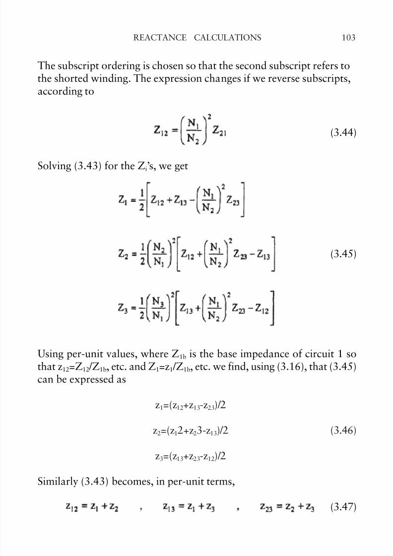
The subscript ordering is chosen so that the second subscript refers tothe shorted winding. The expression changes if we reverse subscripts,according to
(3.44)
Solving (3.43) for the Zi’s, we get
Using per-unit values, where Z1b is the base impedance of circuit 1 sothat z12=Z12 /Z1b, etc. and Z1=z1 /Z1b, etc. we find, using (3.16), that (3.45)can be expressed as
z1=(z12+z13-z23)/2
z2=(z12+z23-z13)/2 (3.46)
z3=(z13+z23-z12)/2
Similarly (3.43) becomes, in per-unit terms,
(3.47)
(3.45)
© 2002 by CRC Press
7/30/2019 Reactance Calculations Tf3080ch3
http://slidepdf.com/reader/full/reactance-calculations-tf3080ch3 18/31
REACTANCE CALCULATIONS104
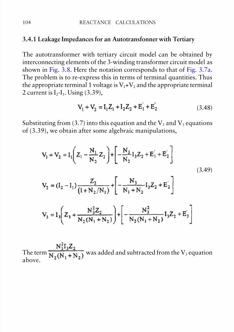
The term was added and subtracted from the V3 equationabove.
3.4.1 Leakage Impedances for an Autotransfonner with Tertiary
The autotransformer with tertiary circuit model can be obtained byinterconnecting elements of the 3-winding transformer circuit model asshown in Fig. 3.8. Here the notation corresponds to that of Fig. 3.7a.The problem is to re-express this in terms of terminal quantities. Thusthe appropriate terminal 1 voltage is V1+V2 and the appropriate terminal2 current is I2-I1. Using (3.39),
(3.48)
Substituting from (3.7) into this equation and the V2 and V3 equationsof (3.39), we obtain after some algebraic manipulations,
(3.49)
© 2002 by CRC Press
7/30/2019 Reactance Calculations Tf3080ch3
http://slidepdf.com/reader/full/reactance-calculations-tf3080ch3 19/31
105REACTANCE CALCULATIONS
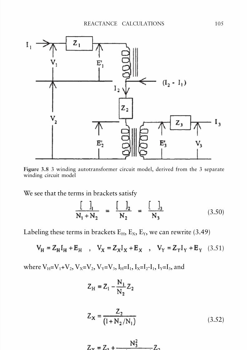
We see that the terms in brackets satisfy
(3.50)
Labeling these terms in brackets EH, EX, EY, we can rewrite (3.49)
(3.51)
where VH=V1+V2, VX=V2, VY=V3, IH=I1, IX=I2-I1, IY=I3, and
Figure 3.8 3 winding autotransformer circuit model, derived from the 3 separatewinding circuit model
(3.52)
© 2002 by CRC Press
7/30/2019 Reactance Calculations Tf3080ch3
http://slidepdf.com/reader/full/reactance-calculations-tf3080ch3 20/31
REACTANCE CALCULATIONS106
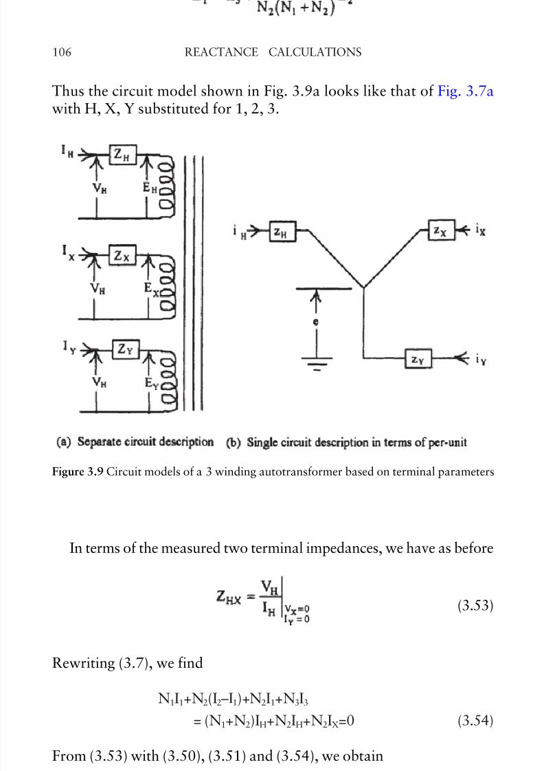
In terms of the measured two terminal impedances, we have as before
(3.53)
Rewriting (3.7), we find
N1I1+N2(I2–I1)+N2I1+N3I3
= (N1+N2)IH+N2IH+N2IX=0 (3.54)
From (3.53) with (3.50), (3.51) and (3.54), we obtain
Thus the circuit model shown in Fig. 3.9a looks like that of Fig. 3.7awith H, X, Y substituted for 1, 2, 3.
Figure 3.9 Circuit models of a 3 winding autotransformer based on terminal parameters
© 2002 by CRC Press
7/30/2019 Reactance Calculations Tf3080ch3
http://slidepdf.com/reader/full/reactance-calculations-tf3080ch3 21/31
107REACTANCE CALCULATIONS
(3.55)
At this point, it is worthwhile to revert to per-unit quantities. Becauseof the auto connection, we have, again choosing the VI per phase ratingof the unit and the rated (no-load) terminal voltages per phase, (VI)b,VHb, VXb, VYb,
since (VI)b is the same for each terminal. From (3.54), we have on a perunit basis,
iH+iX+iY=0 (3.57)
Similarly from (3.50), on a per-unit basis
eH=eX=eY=e (3.58)
On a per-unit basis, (3.55) becomes, using (3.56)
(3.59)
where the same VI base is used for all the terminals. Solving these forzH, zX, zY, we obtain a set of equations similar to (3.46)
(3.56)
© 2002 by CRC Press
7/30/2019 Reactance Calculations Tf3080ch3
http://slidepdf.com/reader/full/reactance-calculations-tf3080ch3 22/31
REACTANCE CALCULATIONS108
(3.60)
Equation (3.52) contains terminal impedances and single coilimpedances and the bases are different for these. Keeping (VI)b the samefor both, we have
Thus, on a per-unit basis, (3.52) becomes
(3.61)
In terms of the terminal turns ratio n=(N1+N2)/N2, (3.62) can bewritten
(3.62)
© 2002 by CRC Press
7/30/2019 Reactance Calculations Tf3080ch3
http://slidepdf.com/reader/full/reactance-calculations-tf3080ch3 23/31
109REACTANCE CALCULATIONS
(3.63)
The per-unit circuit model is depicted in Fig. 3.9b. Note that from (3.45)and (3.46), the autotransformer circuit parameters can be derived from2winding leakage impedance values which, we will see, can be obtainedwith reasonable accuracy, using an analytic formula.
3.4.2 Leakage Impedance between 2 Windings Connected in Series anda Third Winding
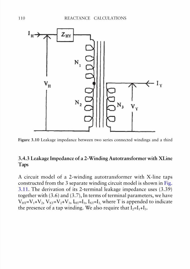
It is useful to calculate the impedance between a pair of windingsconnected in series and a third winding in terms of 2-winding leakageimpedances, as shown in Fig. 3.10. This can be regarded as a specialcase of an autotransformer with the X-terminal open. But, by definition,this leakage impedance is just ZHY. From (3.55) and (3.52), we obtain
(3.64)
or, in per-unit terms, using (3.61)
(3.65)
These can be expressed in terms of 2 winding leakage reactances bymeans of (3.45) and (3.46)
© 2002 by CRC Press
7/30/2019 Reactance Calculations Tf3080ch3
http://slidepdf.com/reader/full/reactance-calculations-tf3080ch3 24/31
REACTANCE CALCULATIONS110
3.4.3 Leakage Impedance of a 2-Winding Autotransformer with XLineTaps
A circuit model of a 2-winding autotransformer with X-line tapsconstructed from the 3 separate winding circuit model is shown in Fig.
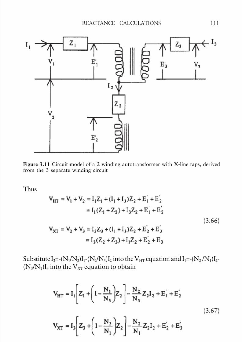
3.11. The derivation of its 2-terminal leakage impedance uses (3.39)together with (3.6) and (3.7), In terms of terminal parameters, we haveVHT=V1+V2, VXT=V2+V3, IHT=I1, IXT=I3, where T is appended to indicatethe presence of a tap winding. We also require that I2=I1+I3.
Figure 3.10 Leakage impedance between two series connected windings and a third
© 2002 by CRC Press
7/30/2019 Reactance Calculations Tf3080ch3
http://slidepdf.com/reader/full/reactance-calculations-tf3080ch3 25/31
111REACTANCE CALCULATIONS
Thus
Figure 3.11 Circuit model of a 2 winding autotransformer with X-line taps, derivedfrom the 3 separate winding circuit
Substitute I3=-(N1 /N3)I1-(N2 /N3)I2 into the VHT equation and I1=-(N2 /N1)I2-(N3 /N1)I3 into the VXT equation to obtain
(3.66)
(3.67)
© 2002 by CRC Press

7/30/2019 Reactance Calculations Tf3080ch3
http://slidepdf.com/reader/full/reactance-calculations-tf3080ch3 26/31
REACTANCE CALCULATIONS112
Add and subtract from the VHT equation and add and
subtract from the VXT equation to obtain, after some
algebraic manipulations,
(3.68)
which can be rewritten
VHT=IHTZHT+EHT . VXT=IXTZXT+EXT (3.69)
where
(3.70)
To obtain the 2 terminal leakage impedance, we use the definition
(3.71)
We have
(3.72)
and from (3.7) we obtain
N1I1+N2(I1+I3)+N3I3=(N1+N2)I1+(N2+N3)I3
=(N1+N2)IHT+(N2+N3)IXT=0 (3.73)
Using (3.69) together with (3.72) and (3.73), we obtain from (3.71)
© 2002 by CRC Press
7/30/2019 Reactance Calculations Tf3080ch3
http://slidepdf.com/reader/full/reactance-calculations-tf3080ch3 27/31
113REACTANCE CALCULATIONS
(3.74)
Using (3.70), this becomes
(3.75)
On a per-unit basis, using a fixed (VI)b and, noting that
we find
(3.76)
This is the two terminal leakage impedance of a 2 windingautotransformer with X-line taps. It can be expressed in terms of the 2winding leakage impedances via equations (3.45) and (3.46).
3.4.4 More General Leakage Impedance Calculations
The cases considered so far cover most of the configurations encounteredin practice. However, other situations can be covered by using theseresults as building blocks. For example, to obtain the leakage impedance
between three windings connected in series and a fourth winding, useformula (3.64) or (3.65) to obtain the leakage impedance between thefourth winding and two of the other windings connected in series. Thenadd the third winding. Considering the two series winding as a singlewinding, calculate the single winding impedances for this new “threewinding” system and reapply (3.64) or (3.65).
Another example would be an autotransformer with tertiary andXline taps. The circuit model for this can be derived from the 2-winding
© 2002 by CRC Press
7/30/2019 Reactance Calculations Tf3080ch3
http://slidepdf.com/reader/full/reactance-calculations-tf3080ch3 28/31
REACTANCE CALCULATIONS114
autotransformer with X-line taps by adding a tertiary winding. Thenthe 2-terminal leakage reactance, equation (3.75) or (3.76), between theseries+common and X-line tap+common, together with the 2-terminalleakage reactances between the tertiary and the series+common andbetween the tertiary and the X-line tap+common can be used toconstruct a 3-terminal impedance model similar to Fig. 3.9.
3.5 TWO WINDING LEAKAGE REACTANCE FORMULA
All of the reactance circuit parameters obtained here for 2 or 3 terminaltransformers can be expressed in terms of 2-winding leakage reactances.These can be calculated by advanced analytical techniques or finiteelement methods which solve Maxwell’s equations directly. Thesemethods are especially useful if the distribution of amp-turns along thewinding is non-uniform, due, for example, to tapped out sections orthinning in sections of windings adjacent to taps in neighboring windings.However, simpler idealized calculations have proven adequate in practice,
particularly at the early design stage. These simpler calculations willbe discussed here but, however these 2-winding reactances are obtained,they can be used directly in the formulas derived previously.
The simple reactance calculation assumes that the amp-turns areuniformly distributed along the windings. It also treats the windings asif they were infinitely long insofar as the magnetic field is concerned,although a correction for fringing at the ends is included in the final
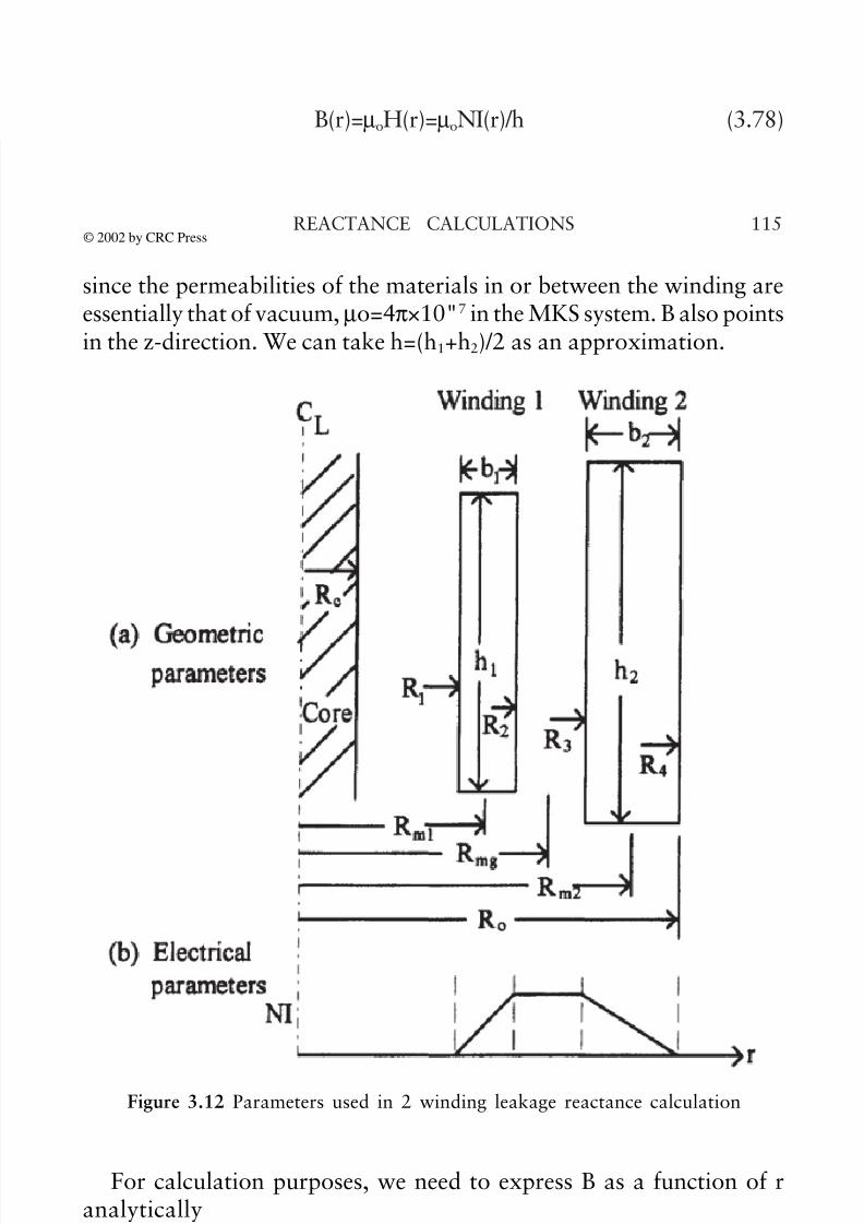
formula. The parameters of interest are shown in Fig. 3.12. If thewindings were infinitely long and the amp-turns per unit length wereequal for the two windings then the magnetic field as a function of radius would be proportional to the amp-turn distribution shown in Fig.3.12b, i.e. in the SI system,
H(r)=NI(r)/h (3.77)
where NI(r) is the function of r shown in the figure, linearly increasingfrom 0 through winding 1, remaining constant in the gap, and decreasingto 0 through winding 2. H is independent of the z-coordinate in thismodel and points vectorially in the z-direction. The flux density istherefore
B(r)=µoH(r)=µoNI(r)/h (3.78)
© 2002 by CRC Press
7/30/2019 Reactance Calculations Tf3080ch3
http://slidepdf.com/reader/full/reactance-calculations-tf3080ch3 29/31
115REACTANCE CALCULATIONS
For calculation purposes, we need to express B as a function of r
analytically
since the permeabilities of the materials in or between the winding areessentially that of vacuum, µo=4π×10"7 in the MKS system. B also pointsin the z-direction. We can take h=(h
1+h
2)/2 as an approximation.
Figure 3.12 Parameters used in 2 winding leakage reactance calculation
(3.79)
© 2002 by CRC Press
7/30/2019 Reactance Calculations Tf3080ch3
http://slidepdf.com/reader/full/reactance-calculations-tf3080ch3 30/31
REACTANCE CALCULATIONS116
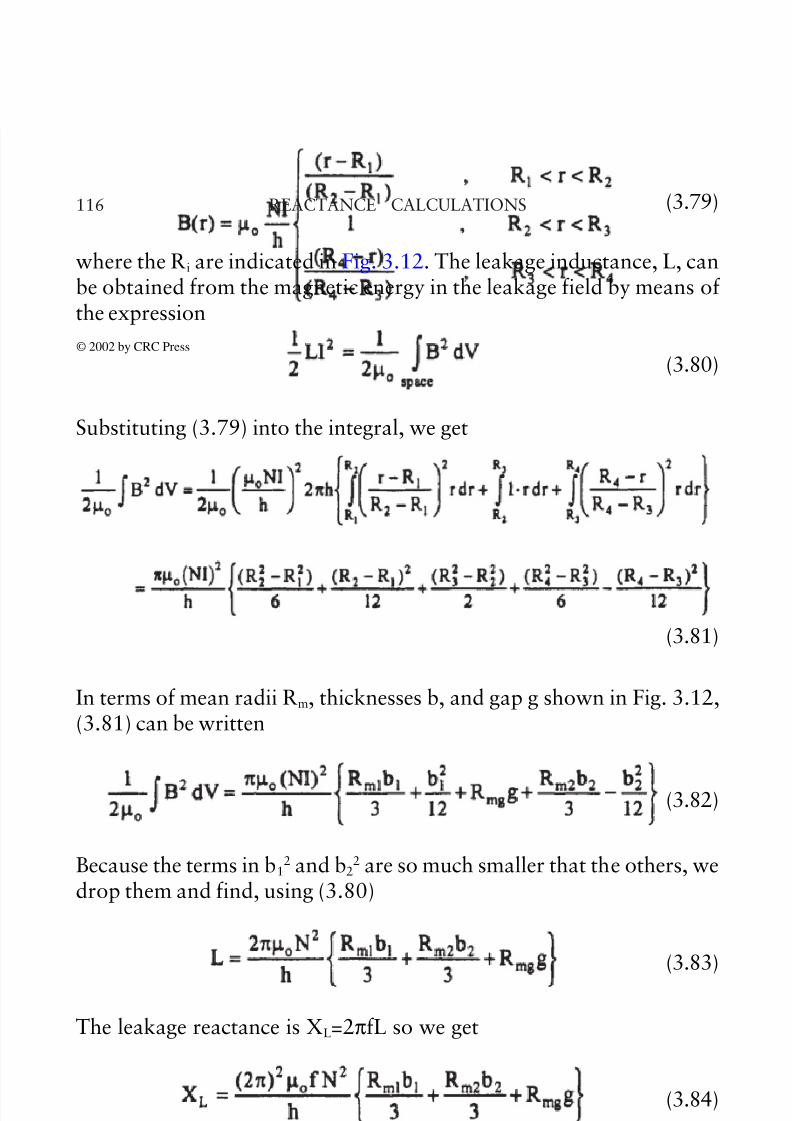
In terms of mean radii Rm, thicknesses b, and gap g shown in Fig. 3.12,
(3.81) can be written
(3.82)
Because the terms in b12 and b2
2 are so much smaller that the others, wedrop them and find, using (3.80)
(3.83)
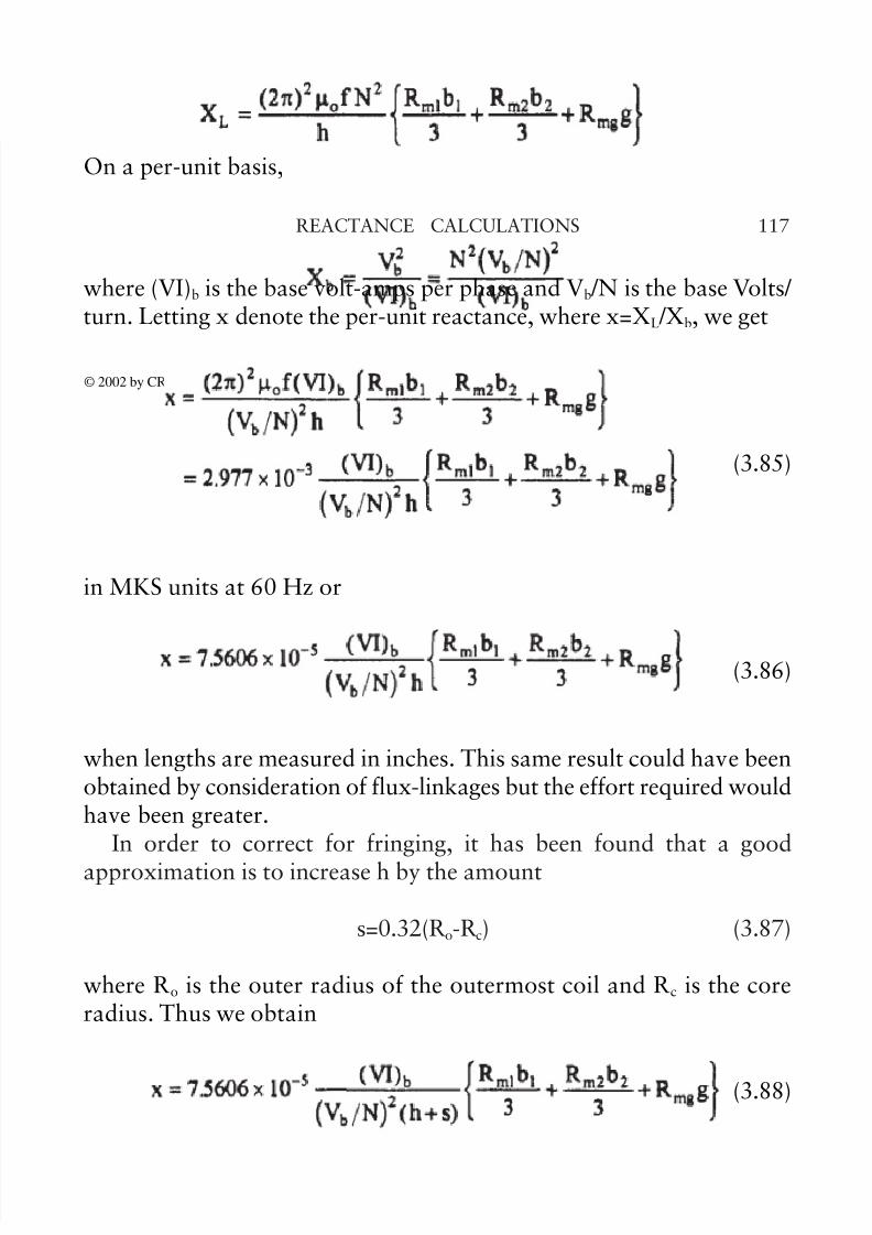
The leakage reactance is XL=2πfL so we get
(3.84)
On a per-unit basis,
where the Ri are indicated in Fig. 3.12. The leakage inductance, L, canbe obtained from the magnetic energy in the leakage field by means of the expression
(3.80)
Substituting (3.79) into the integral, we get
(3.81)
© 2002 by CRC Press
7/30/2019 Reactance Calculations Tf3080ch3
http://slidepdf.com/reader/full/reactance-calculations-tf3080ch3 31/31
117REACTANCE CALCULATIONS
where (VI)b is the base volt-amps per phase and Vb /N is the base Volts/ turn. Letting x denote the per-unit reactance, where x=XL /Xb, we get
(3.85)
in MKS units at 60 Hz or
(3.86)
when lengths are measured in inches. This same result could have been
obtained by consideration of flux-linkages but the effort required wouldhave been greater.
In order to correct for fringing, it has been found that a goodapproximation is to increase h by the amount
s=0.32(Ro-Rc) (3.87)
where Ro is the outer radius of the outermost coil and Rc is the core
radius. Thus we obtain
(3.88)