reactor for process heat, hydrogen and electricity
TRANSCRIPT
CARBOWASTE Treatment and Disposal of Irradiated Graphite and Other Carbonaceous Waste
Grant Agreement Number: FP7-211333
- Technical Report T- 2.5.5 – - Review on technologies to recover TRISO fuel from graphite matrix -
Author(s): F. Cellier, V. Grabon - ANP
Reporting period: 01/04/2008 – 31/03/2010 Date of issue of this report : 28/05/2010
Start date of project : 01/04/2008 Duration : 48 Months
Project co-funded by the European Commission under the Seventh Framework Programme (2007 to 2011) of the European Atomic Energy Community (EURATOM) for nuclear research and training activities
Dissemination Level
PU Public
RE Restricted to the partners of the CARBOWASTE project
CO Confidential, only for specific distribution list defined on this document X
CARBOWASTE
Treatment and Disposal of Irradiated Graphite and Other Carbonaceous Waste
Distribution list
Person and organisation name and/or group
Comments
WP 2 partners
G. Cardinal, CEA
D. Hittner, ANP Inc
B. Grambow, Subatech
D. Vulpius, FZJ
W. von Lensa, FZJ
Page 2/27
CW1003-T-2-5-5-a AREVA
CARBOWASTE Treatment and Disposal of Irradiated Graphite and Other Carbonaceous Waste
CARBOWASTE
Work package: 2 Task: : 2.5
CARBOWASTE document no: CARBOWASTE-1003-T-2.5.5
(e.g. May 2008 as date of issue: 0805)
Document type: T=Technical Report
Issued by: AREVA - ANP (France) Internal no.: PVEK DC 05 0029 A
Document status: final
Document title
Review on technologies to recover TRISO fuel from graphite matrix
Executive summary This report provides the results of some previous studies performed in AREVA in the frame of the ANTARES program to assess HTR compact/fuel particle separation methods for further reprocessing (see [9]). This document complements the work performed by FZJ in the frame of the CARBOWASTE WP2 (see [10]).
Methods consisting in successive grinding and burning are considered as the reference and technically most advanced head-end process for HTR fuel reprocessing. The major drawbacks are the off-gas treatment and the dust management. Some other innovative technologies for separating fuel particles from the graphite matrix of compact have been identified:
disintegration by electrical pulse
disintegration by ultrasounds
treatment by hydrofluorination
combustion in molten salts Physical methods require further sorting out of fuel particles and eventual further combustion of residual carbon. Chemical methods require preliminary destructuration of compacts. Except disintegration by ultrasounds, these methods have been proved to allow the elimination of the particle SiC coating. It is still difficult at this stage to privilege one method of compact /fuel separation since elements such as economical point of view have not been assessed and even technical feasibility is still not demonstrated on entire compact. However the most promising innovative technologies to be tested and compared with the classical methods (grinding/burning) performance, appear to be the disintegration by electrical pulse and the treatment in molten salts. With regard to nuclear constraints, these methods carried out in liquid phase are of interest since they do they do not induce dust spreading. Nevertheless treatment in molten salt should be carried out at high temperature and generates gas to be treated. Thus it is important to pursue and follow the electrical pulse tests performed by CEA. Disintegration by ultrasound should be investigated through a bibliographical review to determine if further experiments of this method on compact would be of interest. Treatment in molten salts should be investigated prior to hydrofluorination (HF/O2) since this latter treatment in gas phase requires dust management. In addition hydrofluorination requires more preliminary treatment steps (crushing of fuel particles and burning off in oxygen).
Page 3/27
CW1003-T-2-5-5-a AREVA
CARBOWASTE Treatment and Disposal of Irradiated Graphite and Other Carbonaceous Waste
Revisions
Rev. Date Short description Author Internal Review Task Leader WP Leader
00
27/05/2010 1. Issue
F. Cellier, ANP V. Grabon, ANP
v. Lensa, FZJ
v. Lensa, FZJ
Page 4/27
CW1003-T-2-5-5-a AREVA

CARBOWASTE Treatment and Disposal of Irradiated Graphite and Other Carbonaceous Waste
List of Content
1 Introduction.......................................................................................................................... 6 2 Feedback of relevant experience.......................................................................................... 7
2.1 Feedback from former HTR......................................................................................... 7 2.2 Feedback from UNGG................................................................................................. 9
3 Review of available technologies ........................................................................................ 9 3.1 Grinding ..................................................................................................................... 10 3.2 Electrical pulses ......................................................................................................... 11 3.3 Ultrasound.................................................................................................................. 12 3.4 Combustion ................................................................................................................ 13 3.5 Treatment by halogen gas .......................................................................................... 13 3.6 Treatment in molten salt ............................................................................................ 14
4 Identification of R&D needs.............................................................................................. 15 5 Conclusion/recommendation ............................................................................................. 16 6 Figures & Tables................................................................................................................ 18 7 References.......................................................................................................................... 27
Page 5/27
CW1003-T-2-5-5-a AREVA
CARBOWASTE Treatment and Disposal of Irradiated Graphite and Other Carbonaceous Waste
1 Introduction
This report provides the results of some previous studies performed in AREVA in the
frame of the ANTARES program to assess HTR compact/fuel particle separation methods for
further reprocessing (see [9]). This document complements the work performed by FZJ in the
frame of the CARBOWASTE WP2 (see [10]).
The HTR spent fuel includes significant amounts of carbon and SiC waste, since the fuel
kernels account for only few percent of the entire fuel element mass (see figure 1). This
characteristic is specific of HTR design and is different from most other reactor types. With
regard to direct disposal of spent fuel as High Level Waste (path A on figure 2), separating the
fuel compacts from the fuel elements allows the disposal or recycling of moderator graphite -
which represents the bulk of the waste volume - as Low Level Waste. Reprocessing fuel
particles allows recycling of elements of interest (uranium, plutonium) that would reduce the
radiotoxicity of the final waste. It allows the dissociation of problems linked with Carbon 14
release from those linked with fission products treatment. This way is identified as path C
among the different options on figure 2.
The separation of compacts from the graphite fuel assembly is assumed to be achieved in
a first step by physical processes (mechanical extraction, electrical pulse, ultrasounds). The
scope of this work is to examine the technologies that are currently available for separating the
fuel particles from the graphite matrix of the compact and to identify R&D needs in this area.
The aim is to recover the bare fuel kernel without its coating layers – particularly the silicon
carbide coating – to allow further dissolution of fuel kernel in nitric acid prior to chemical
separation and recovery of the valuable fuel elements (U, Pu).
The difficulties to separate fuel kernels from the compact graphite are due to compact
characteristics. Fuel kernels represent about 18% of the compact mass [1] but only 2.5% of the
compact volume and is dispersed in numerous little particles of diameter 920 µm (500µm UO2
diameter, 95µm buffer, 40µm PyC internal layer, 35µm SiC layer, 40µm PyC external layer).
The SiC coating is characterized by its high thermal and chemical stability.
Page 6/27
CW1003-T-2-5-5-a AREVA
CARBOWASTE Treatment and Disposal of Irradiated Graphite and Other Carbonaceous Waste
Available technologies for separating fuel particles from graphite compacts have been
identified through a preliminary bibliographical review.
2 Feedback of relevant experience
HTR fuel particles reprocessing experience is gained through former HTR development:
Peach Bottom, Fort St.Vrain in USA, AVR in Germany. Some information about graphite
treatment also issue from the feedback of Natural Uranium Graphite Gas reactors (UNGG).
2.1 Feedback from former HTR
HTR fuel reprocessing has already been studied and experienced in 1960-1980 [2], [3],
[4] in the USA (Oak Ridge National Laboratory, General Atomic Corporation, Allied Chemical
Corporation) and in Germany (Forschungszentrum Jülich).
All methods used to separate fuel particle from graphite (compact or pebble) consist in
successive grinding and burning steps. Grinding gives access to the fuel particles and enhances
the reactive surface for burning. Burning is used to remove the large amount of graphite
compared with the relatively small amount of fuel material. This procedure is considered as the
reference and technically most advanced head-end process for HTR fuel.
Grinding
The fuel must be crushed to suitable particle size for maintaining fluidization quality
during further combustion in the fluidized-bed burner. Different types of grinding machines
have been used: jaw crushers, hammer crushers, pebble crushers, crushing rollers, etc. For
example the process developed by ORNL for primary crushing of compacts is described on
figure 3 [2]. Generally the size of the obtained particles - in the order of few millimetres – was
still high with regard to the fuel particles diameter (250 µm fuel oxide diameter) to minimize
fuel particle breakage and to prevent undesirable cross-over of fuel. Only few percent of the
particle SiC coatings are broken. Thus, after burning, the particles are sent through a small roll
crusher or jet grinder for a second crushing in order to break the SiC shell. About 5% of the
fuel particles stayed intact and inaccessible for further dissolution. During grinding sorting of
Page 7/27
CW1003-T-2-5-5-a AREVA

CARBOWASTE Treatment and Disposal of Irradiated Graphite and Other Carbonaceous Waste
the particles is necessary with recycling of larger particles. Pneumatic or cyclone separators are
often used.
Burning
After grinding, combustion is carried out in fluidized bed burners operating at
temperature up to 950°C. Processes are different depending on the temperature of combustion.
At low temperature the SiC coating remains intact because of its high thermal stability. To
destroy it, the burning temperature should be higher than 1300°C, but it would involve the
volatilization of fission products that would lead to difficulties to treat exhaust gases.
US process [2] consists in primary burning at 850-875°C (so-called "exothermic") to
remove the graphite and the outer pyrolytic carbon coating from the TRISO particles. Then,
after second crushing to break the SiC coating, particles are burned in a secondary fluidized
bed burner (so-called "endothermic") to remove the inner carbon coatings. Generally about
95% of fissile elements were recovered. Carbon residues due to non complete combustion are
reported to form carboxylic acids during further dissolution in nitric acid, that lead to
difficulties during separation processes.
The primary burner is the main source of off-gas: carbon dioxide with associated
relatively very small volumes of radioactive gases 85Kr, 129I, 220Rn, 3H, and also entrained
fines. Fines are removed through cyclone and/or sintered metal filter to be recycled while
exhaust gases pass through off-gas treatment. ORNL off-gas treatment [2] consists in removal
of krypton by absorption by liquid carbon dioxide (KALC process), removal of iodine by lead
and silver zeolites, hold up of radon on molecular sieve to permit decay to solid products and
tritium removal in the form of tritiated water on molecular sieve. Off-gas treatment was not
optimized with regard to carbone 14 release.
As said previously, the crushed compacts introduced in the primary burner may contain a
small but still significant fraction of particles with broken SiC coating. According to
experiments carried out between 700-900°C [5], the kernel of damaged particles is oxidized to
U3O8 [4] associated with exothermic conversion, considerable swelling and disintegration of
kernels into dust. Thus a non-negligible fraction of dusty heavy metal is to be expected in the
exhaust gas.
Page 8/27
CW1003-T-2-5-5-a AREVA
CARBOWASTE Treatment and Disposal of Irradiated Graphite and Other Carbonaceous Waste
2.2 Feedback from UNGG
A prototype incinerator was built in the 90s in Le Creusot in France in order to treat the
graphite issued from French graphite gas-cooled reactors (UNGG commissioned in 1950-
1970s) [6]. Graphite waste is mainly in the form of spent fuel sleeves or graphite blocks.
Graphite blocks are first crushed by shredder, hammer-type and cylindrical crushers in
order to obtain a final average particle size of one millimeter. The particle size is expected to
be larger than 100 µm to limit dust dissemination and dust explosion risk. The crushing station
is located inside an enclosure kept under negative pressure, swept by high air flow rate and
filtered. Thus inerting of the crushing room did not seem to be necessary.
Then the crushed graphite is burned in a circulating fluidized bed incinerator. The
fluidized bed consists of powdered refractory material under high air flow rate and high
turbulence. Solid particles are separated from the combustion gases through a cyclone
separator and recycled by a recirculating loop with no moving mechanical parts. Incineration of
the unburned graphite contained in the combustion gases leaving the cyclone separator is
completed in a post-combustion chamber. The tightness of the combustor allows it to work
under relative negative pressure. Emitters 3H and 14C are released in the atmosphere with
gradual and controlled dilution. An impact assessment of graphite incineration on the
environment was performed.
A validation program was carried out on the prototype incinerator. Combustion was
complete and well-controlled.
3 Review of available technologies
Different technologies using physical or chemical methods have been identified for
compact/fuel separation.
Physical methods:
Grinding
Electrical pulses
Page 9/27
CW1003-T-2-5-5-a AREVA
CARBOWASTE Treatment and Disposal of Irradiated Graphite and Other Carbonaceous Waste
Ultrasound Chemical methods:
Combustion
Treatment by halogen gas
Treatment in molten salts
3.1 Grinding
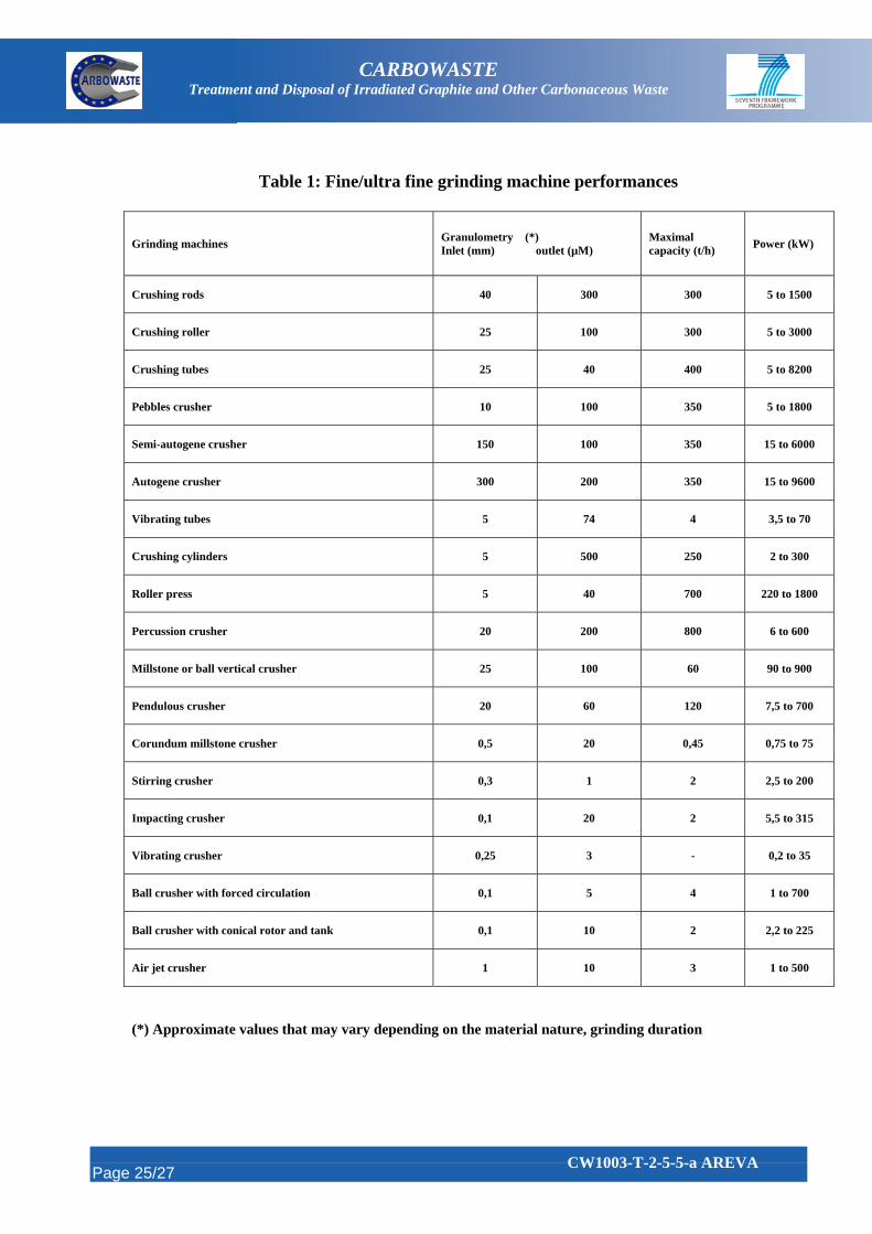
With regard to the past experience and to the performance of existing fine/ultra fine
grinding machines (see table 1), it could be expected to reach graphite particles granulometry
close to the fuel particle diameter or lower. Separation method of graphite from fuel particle
based on particle size difference could only be used if SiC coatings remain intact during
grinding. However fuel particles would be broken during fine grinding. A separation method
based on particle density difference has been performed in Germany for HTR fuel sphere
(pebble design) and allowed pre-separation of 90% of the main matrix graphite prior to a
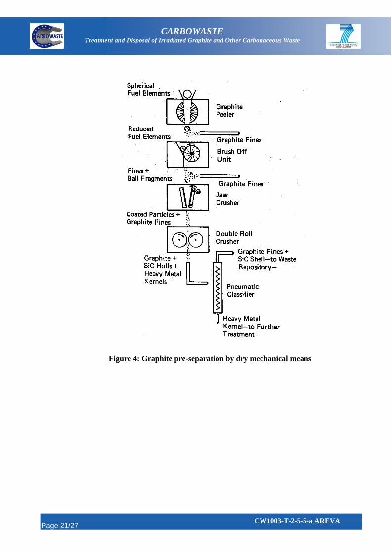
further treatment [7]. The process principle is shown on figure 4. First the graphite sphere is
introduced in a peeling and brush-off unit to remove the outer heavy metal-free zone. Then the
remaining sphere is disintegrated by rotating metal brushes. Graphite fines are removed at each
step. The residual fragments are crushed by jaw crusher. It is noteworthy that the coated
particles remain intact at this stage. In the further crushing step SiC shells are broken. Kernel
particles (density about 10) are separated from graphite fines (density about 1.7) and SiC shells
by gas elutriation through a pneumatic classifier. However the remaining carbon residue of
about 10% has to be burned.
Constraints associated to grinding are dust dissemination, abrasion of moving pieces,
further treatment required to eliminate graphite. Advantage is generally high capacity.
Grinding is an available technology only to be used as a pre-treatment or a pre-separation
method of fuel particles from the main part of graphite prior to further treatment.
Page 10/27
CW1003-T-2-5-5-a AREVA
CARBOWASTE Treatment and Disposal of Irradiated Graphite and Other Carbonaceous Waste
3.2 Electrical pulses
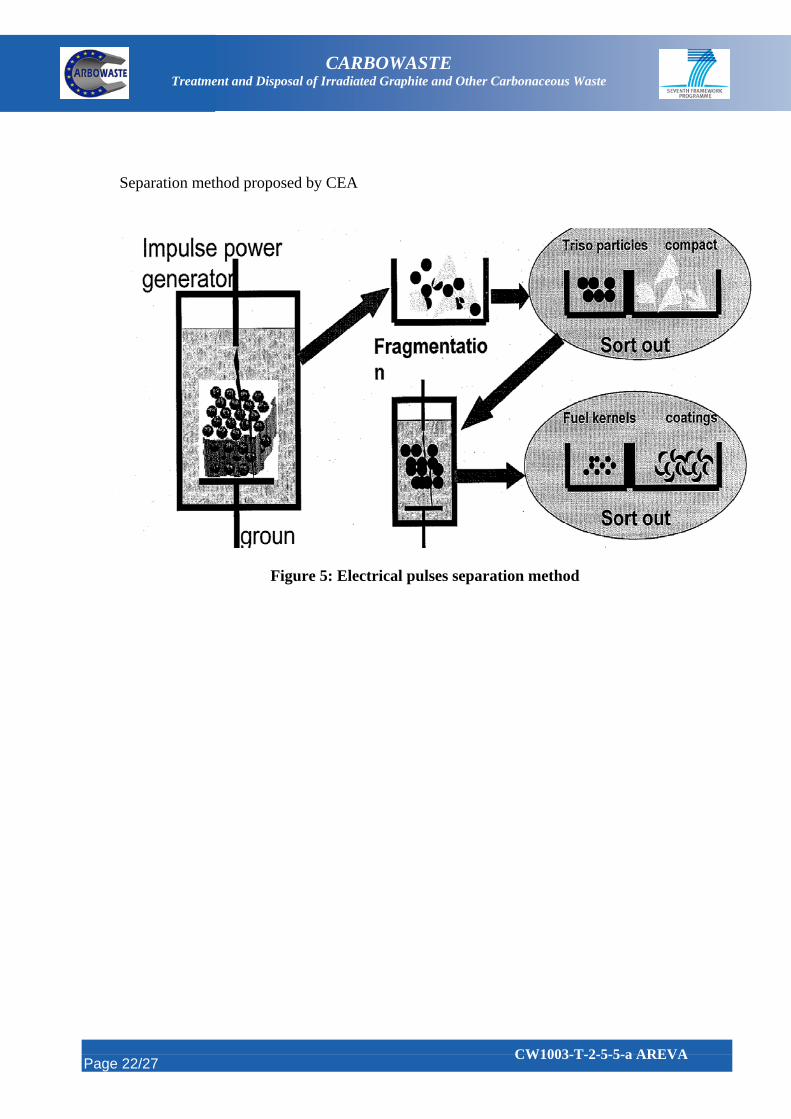
Fragmentation of solids is induced by high voltage electrical pulses. Electric energy is
stored in capacitors and discharged in very short time through the solid between two electrodes
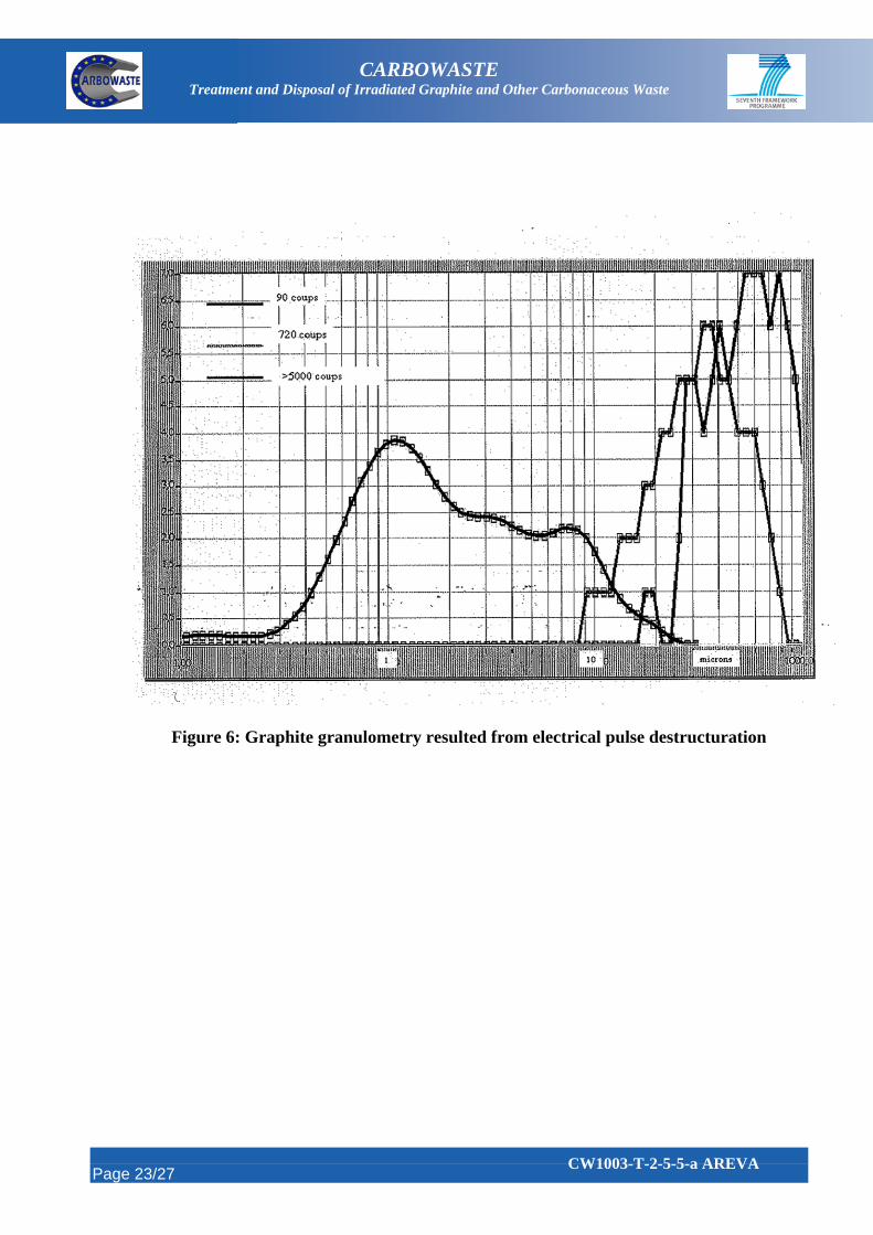
(see figure 5). The solid is immersed in water. In heterogeneous materials, fragmentation
occurs at the interface between the different constituents. Fine granulometry may be obtained
on graphite (see figure 6).
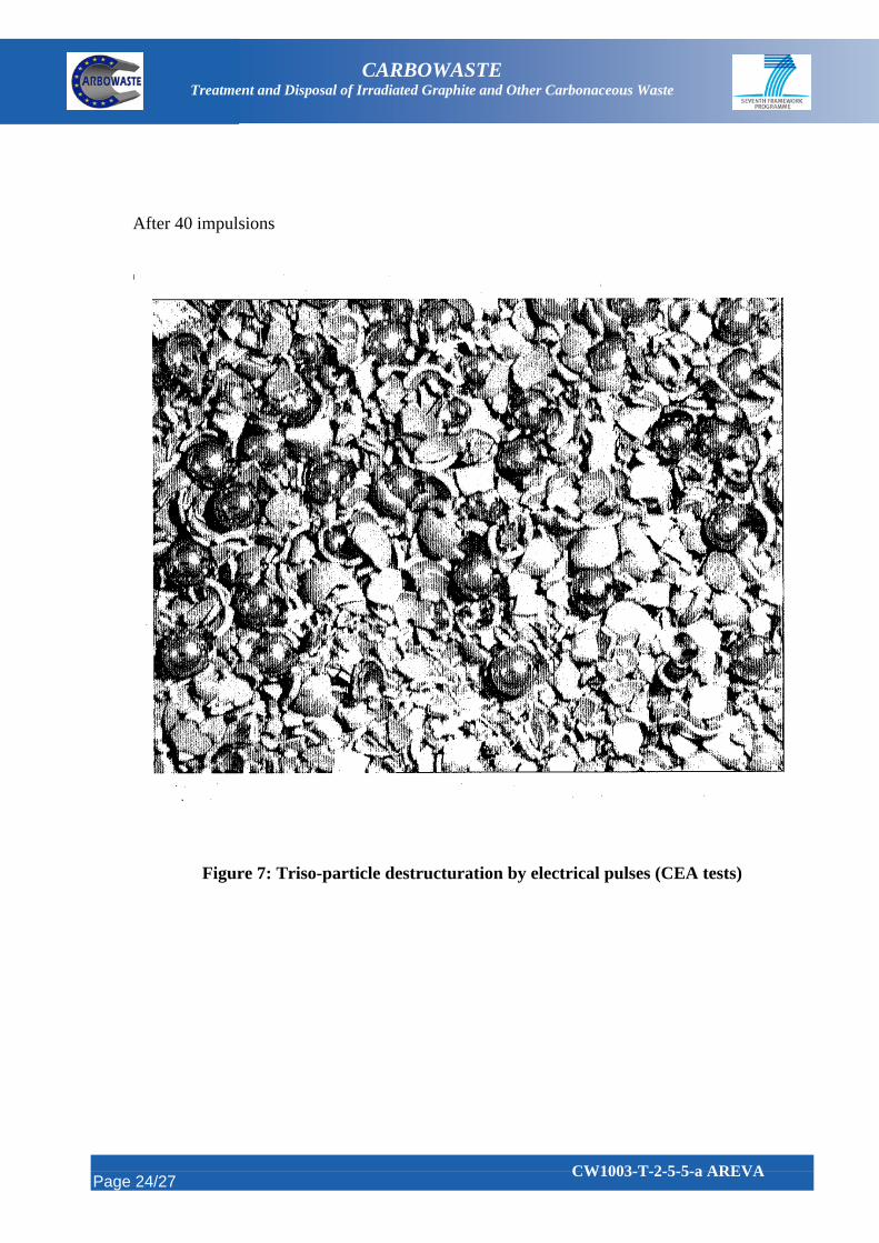
This technology is currently being investigated by CEA. Feasibility tests were carried out
in June 2004 in which graphite and SiC samples and TRISO particles were submitted to the
direct process (also called localized process : electrical arc is directly applied to the sample)
using MAX pulse generator. Applied conditions were:
Energy level: 500 J
Voltage: 250 kV
Impulsion duration: 200 ns
Peak intensity: 6 kA
Adjustable parameters were impulsion number and time between impulsions.
Interesting results have been obtained on TRISO particles (see figure 7): Nearly total
destructuration of particle coatings after 40 impulsions whereas the fuel kernels remain intact.
This process would allow further dissolution of bare fuel kernels after sorting out of cracked
SiC shells from the fuel kernels (see figure 5).
It is expected that destructuration by electrical pulse technology applied to the entire
compact could allow the recovering of fuel particles from the bulk compact graphite assuming
that sorting out of fuel particles is possible as shown on figure 5.
Interests of this method are short time treatment and no dust management as the solid
destructuration is carried out under water.
Nevertheless further studies and tests are needed to demonstrate the feasibility of this
technology according to following requirements:
performance on representative samples (compact with TRISO particles)
Page 11/27
CW1003-T-2-5-5-a AREVA
CARBOWASTE Treatment and Disposal of Irradiated Graphite and Other Carbonaceous Waste
nuclear application of this technology
application to high capacity (feasibility tests were limited to little samples : 3 g
TRISO particles)
development of particles sorting out
energy consumption
3.3 Ultrasound
Ultrasound waves may produce heavy effect on material depending on the transmitted
power. For disintegration applications ultrasound power ranging from some watts to several
kilowatts is applied with an ultrasound frequency of about 20 kHz. Ultrasounds are transmitted
through a liquid medium; generally the piece is immersed in water containing abrasive
particles. Ultrasounds induce particles vibrations. The disintegration of the solid results from
the mechanical action of the particles - shocks and friction due to particles vibrations - and
from the cavitation effect due to pressure variations inside water. This technology is used to
machine hard and fragile or porous materials. Theoretically graphite could be easily
disintegrated by this process whereas disintegration of harder and less fragile material as SiC
would be more difficult and would lead to heavy wear of the sonotrode. Generally silicon
carbide is used as abrasive particles for graphite. It has been shown that the optimum size of
abrasive particles is in the order of 100 µm to obtained maximal disintegration rate.
If the disintegration of compact could reduce graphite to fine particles - compared with
the fuel particles size – and without damage to particle SiC coating, sorting out of intact fuel
coated particle could be possible. Then fuel coated particles could be treated separately from
the relatively large quantity of graphite. This method would not require dust management since
it is carried out in liquid phase.
Preliminary study and tests would be necessary to assess the feasibility of this method
applied to compact disintegration. Application to high treatment capacity should be
demonstrated.
Page 12/27
CW1003-T-2-5-5-a AREVA

CARBOWASTE Treatment and Disposal of Irradiated Graphite and Other Carbonaceous Waste
3.4 Combustion
Burning of compact issued from former HTR in fluidized bed has been largely developed
in the past. This technology requires preliminary grinding of compacts. By burning, the main
graphite is eliminated. As said previously, the elimination of SiC particle coating can be
expected only at very high temperature combustion leading to undesirable volatilization of
fission products. Thus after burning at usual temperature (700-900°C) further treatments will
be required to break the SiC coating (fine grinding) and to eliminate inner carbon layers
(secondary burning or other chemical method) to recover the fuel kernel.
The main difficulties consist in the management of contaminated dust and in the
treatment of combustion gases.
3.5 Treatment by halogen gas
Treatment by halogen gas allows the elimination of the SiC particle coating. After
grinding of compacts, SiC can be removed by elementary fluorine or chlorine at very high
temperature (>1500°C) as proposed by Argon National Laboratory (USA).
The reaction (given for fluorine),
SiC + 4 F2 SiF4 + CF4 (fluorination)
is strongly exothermic and may result in a sintering of the particles. It leads to the
volatilization of fission products and of uranium in the form of UF6 and to the formation of the
following volatile halogen species [7][8]:
CFx, SiF4, UF6, PuF6.
The presence of SiF4 in the fluorination exhaust gas causes difficulties in the separation
and purification of UF6.
According to German authors [8], this problem could be avoided by another method
allowing the particles treatment at lower temperature. This method consists in
hydrofluorination. SiC does not react with HF directly, but in a HF/O2 mixture. The entire
PyC/SiC/PyC coating of particles could be totally removed at low temperature (about 500°C):
Page 13/27
CW1003-T-2-5-5-a AREVA

CARBOWASTE Treatment and Disposal of Irradiated Graphite and Other Carbonaceous Waste
SiC + 4 HF + 2 O2 SiF4 + 2 H2O + CO2
This method also requires preliminary grinding of the particles (to about 200 µm) and
burning off the PyC layer with oxygen at about 800°C. In these conditions SiC can be removed
by hydrofluorination at a temperature lower than 700°C at which severe corrosion problems
may occur. However corrosion resistant material (Nickel, Monel) must be preferred for the
hydrofluorination reaction vessel.
The feasibility of hydrofluorination in HF/O2 mixture has been demonstrated with good
efficiency for limited batches. Total elimination of SiC has been obtained after some hours in
HF/O2 in a fluidized bed reactor at 500°C on 150 g batches of oxygen treated particles.
3.6 Treatment in molten salt
Treatments by molten salts are also to be investigated.
This method consists of carrying out the combustion by oxygen or nitrogen dioxide in
molten salt medium. Preliminary studies showed that the combustion kinetic close to dry
combustion kinetic may be expected at high temperature (> 900°C).
The main interest of molten salt is that on one hand SiC may be eliminated and on the
other hand the carbon may be partially used to dissolve fuel oxides according to the chemical
reactions (for molten chloride application):
2 Cl2 + C CCl4
2 Cl2 + SiC C + SiCl4
MO2 + 4 Cl2 + 2 C MCl4 + 2 COCl2
Carbon and SiC are eliminated in the form of volatile halogen products whereas actinides
and fission products may be recovered in the molten chloride solution by electrolyse or
selective oxide precipitation.
The other main advantage of this method (as with any method carried out in the liquid
phase) is that it does not require dust management. Nevertheless corrosion problems must be
taken into account.
Page 14/27
CW1003-T-2-5-5-a AREVA

CARBOWASTE Treatment and Disposal of Irradiated Graphite and Other Carbonaceous Waste
Similar treatments in molten sodium hydroxide or in molten carbonates are also reported.
These treatments would generate carbon dioxide and solid silicate. Actinides could be
recovered by classical process (PUREX for Uranium and Plutonium) from nitric medium.
4 Identification of R&D needs
It is obvious that several criteria must be taken into account for methods assessment:
Performance in terms of: kinetic, % of obtained bare fuel particles or % of
recovered fuel, treatment capacity
Implementation constraints (associated problems: dust dissemination, abrasion,
corrosion…)
Effluent/waste management
Nuclear constraints (treatment of nuclear material with respect to criticality,
shielding, dose, proliferation, etc)
Economical point of view
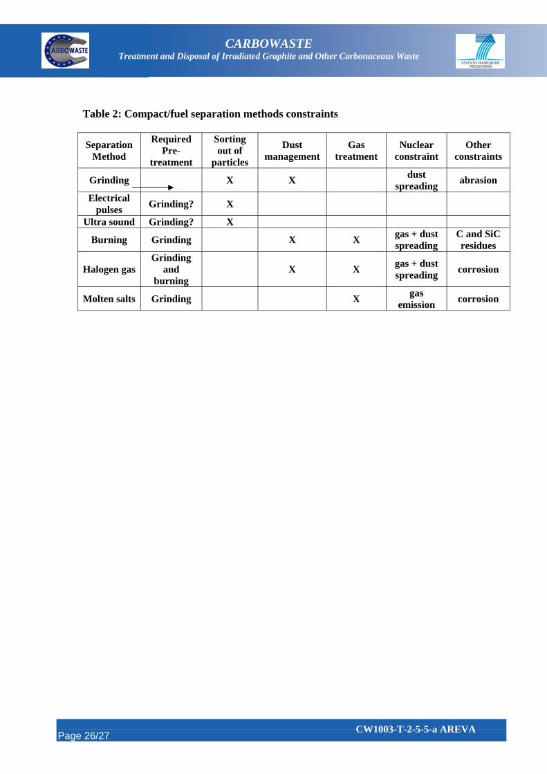
Constraints and requirements associated to the identified methods are summarized in
table 2.
All physical methods are only expected to give access to the fuel particles but require
further sorting out to recover fuel particles.
Electrical pulse appears to be one of the most attractive technologies which allow the
elimination of the SiC coating to recover the intact fuel kernels assuming that sorting out is
possible. Application to the disintegration of entire compact and to high capacity treatment is
still to be demonstrated.
Grinding could be considered as pre-treatment/pre-separation for other methods.
Grinding by steps would allow pre-separation of the main graphite followed by SiC breakage
and recovering of fuel kernel by gas elutriation. Nevertheless this method requires further
treatment (burning) to eliminate residual carbon.
Page 15/27
CW1003-T-2-5-5-a AREVA

CARBOWASTE Treatment and Disposal of Irradiated Graphite and Other Carbonaceous Waste
All methods would require preliminary grinding of compacts except if destructuration by
electrical pulses or by ultrasound technologies are proved to be directly applicable to compacts
(electrical pulse tests to be performed by CEA).
Classical chemical treatments (burning) allow the recovering of fuel particles by
elimination of the graphite and PyC coatings. But additional intermediate grinding step is
required for breakage of the particle SiC coating. Classical burning methods require off-gas
treatment and dust management.
Compared with classical combustion, chemical processes such as hydrofluorination
(HF/O2) or treatment in molten salts would allow the elimination of SiC coating without
formation of volatile compounds of actinides and fission products.
However, whereas classical methods - fluidized bed burning of crushed graphite material
- have been experienced and developed to an advanced stage, the feasibility of these innovative
methods - particularly the feasibility of treatment of compacts by molten salts - remains to be
demonstrated and to be assessed in terms of performance on high capacity treatment and taking
into account other associated constraints (corrosion).
The advantage of methods carried out in liquid phase (electrical pulses, ultrasounds,
molten salts) is that dust management is not required.
5 Conclusion/recommendation
It is still difficult at this stage to privilege one method of compact /fuel separation since
elements such as economical point of view have not been assessed and sometimes even
technical feasibility is still not demonstrated.
However the most promising innovative technologies to be tested and compared with the
classical methods (grinding/burning) performance, appear to be the disintegration by electrical
pulse and the treatment in molten salts. With regard to nuclear constraints, these methods
carried out in liquid phase are of interest since they do not induce dust spreading. Nevertheless
treatment in molten salt should be carried out at high temperature and generates gas to be
treated.
Page 16/27
CW1003-T-2-5-5-a AREVA
CARBOWASTE Treatment and Disposal of Irradiated Graphite and Other Carbonaceous Waste
Thus it is important to pursue and follow the electrical pulse tests performed by CEA.
Disintegration by ultrasound should be investigated through a bibliographical review to
determine if further experiments of this method on compact would be of interest.
Treatment in molten salts should be investigated prior to hydrofluorination (HF/O2)
since this latter treatment in gas phase requires dust management. In addition hydrofluorination
requires more preliminary treatment steps (crushing of fuel particles and burning off in
oxygen).
Page 17/27
CW1003-T-2-5-5-a AREVA
CARBOWASTE Treatment and Disposal of Irradiated Graphite and Other Carbonaceous Waste
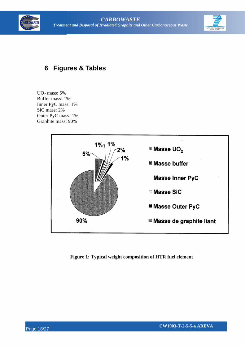
6 Figures & Tables UO2 mass: 5% Buffer mass: 1% Inner PyC mass: 1% SiC mass: 2% Outer PyC mass: 1% Graphite mass: 90%
Figure 1: Typical weight composition of HTR fuel element
Page 18/27
CW1003-T-2-5-5-a AREVA

CARBOWASTE Treatment and Disposal of Irradiated Graphite and Other Carbonaceous Waste
Figure 2: HTR spent fuel treatment options
Page 19/27
CW1003-T-2-5-5-a AREVA

CARBOWASTE Treatment and Disposal of Irradiated Graphite and Other Carbonaceous Waste
Figure 3: Schematic diagram of ORNL crushing system
Page 20/27
CW1003-T-2-5-5-a AREVA
CARBOWASTE Treatment and Disposal of Irradiated Graphite and Other Carbonaceous Waste
Figure 4: Graphite pre-separation by dry mechanical means
Page 21/27
CW1003-T-2-5-5-a AREVA
CARBOWASTE Treatment and Disposal of Irradiated Graphite and Other Carbonaceous Waste
Separation method proposed by CEA
Figure 5: Electrical pulses separation method
Page 22/27
CW1003-T-2-5-5-a AREVA
CARBOWASTE Treatment and Disposal of Irradiated Graphite and Other Carbonaceous Waste
Figure 6: Graphite granulometry resulted from electrical pulse destructuration
Page 23/27
CW1003-T-2-5-5-a AREVA
CARBOWASTE Treatment and Disposal of Irradiated Graphite and Other Carbonaceous Waste
After 40 impulsions
Figure 7: Triso-particle destructuration by electrical pulses (CEA tests)
Page 24/27
CW1003-T-2-5-5-a AREVA
CARBOWASTE Treatment and Disposal of Irradiated Graphite and Other Carbonaceous Waste
Table 1: Fine/ultra fine grinding machine performances
Grinding machines Granulometry (*) Inlet (mm) outlet (µM)
Maximal capacity (t/h)
Power (kW)
Crushing rods 40 300 300 5 to 1500
Crushing roller 25 100 300 5 to 3000
Crushing tubes 25 40 400 5 to 8200
Pebbles crusher 10 100 350 5 to 1800
Semi-autogene crusher 150 100 350 15 to 6000
Autogene crusher 300 200 350 15 to 9600
Vibrating tubes 5 74 4 3,5 to 70
Crushing cylinders 5 500 250 2 to 300
Roller press 5 40 700 220 to 1800
Percussion crusher 20 200 800 6 to 600
Millstone or ball vertical crusher 25 100 60 90 to 900
Pendulous crusher 20 60 120 7,5 to 700
Corundum millstone crusher 0,5 20 0,45 0,75 to 75
Stirring crusher 0,3 1 2 2,5 to 200
Impacting crusher 0,1 20 2 5,5 to 315
Vibrating crusher 0,25 3 - 0,2 to 35
Ball crusher with forced circulation 0,1 5 4 1 to 700
Ball crusher with conical rotor and tank 0,1 10 2 2,2 to 225
Air jet crusher 1 10 3 1 to 500
(*) Approximate values that may vary depending on the material nature, grinding duration
Page 25/27
CW1003-T-2-5-5-a AREVA
CARBOWASTE Treatment and Disposal of Irradiated Graphite and Other Carbonaceous Waste
Table 2: Compact/fuel separation methods constraints
Required Pre-
treatment
Sorting out of
particles
Dust management
Gas treatment
Nuclear constraint
Other constraints
Separation Method
X X
dust spreading
abrasion Grinding
Electrical pulses
Grinding? X
Ultra sound Grinding? X gas + dust spreading
C and SiC residues
Burning Grinding X X
Grinding and
burning Halogen gas X X
gas + dust spreading
corrosion
gas emission
corrosion Molten salts Grinding X
Page 26/27
CW1003-T-2-5-5-a AREVA

Page 27/27
CARBOWASTE Treatment and Disposal of Irradiated Graphite and Other Carbonaceous Waste
CW1003-T-2-5-5-a AREVA
7 References
[1] Technical Data Record 12-5052394-00- ANTARES Spent Fuel Quantities
[2] K.J.Notz – An overview of HTGR Fuel Recycle – ORNL –TM-4747 report, January 1976
[3] F.A.Schwarz, H.E.Tischer, R.N.Drake, W.S.Rickman,N.D.Holder, J.B.Strand –
Unirradiated high temperature reactor fuel element head-end reprocessing tests – Nuclear
Technology, vol.58, July 1982
[4] U.Brinkmann, W.Heit, H.Huschka, G.Kaiser, W.Theymann – Research and development
work in HTR fuel fabrication fuel performance and spent fuel treatment in the FRG – Gas
Cooled Reactors Today, Proceedings vol.2, BNES, London, 1982
[5] N.Hoogen, H.G.Aschhoff, G.Staib – Conversion of uranium nuclear fuel into U3O8 at the
head end of HTR reprocessing – Journal of Nuclear Materials 120 (1984) 217-222
[6] J.J.Guiroy – Graphite waste incineration in a fluidized bed – IAEA-TECDOC-901-
Graphite moderator lifecycle behaviour - Proceedings of a specialists meeting held in Bath,
United Kingdom, 24-27 September 1995
[7] N.G.Hoogen, E.R.Merz – Evaluation of potential head-end procedures for graphite-
containing fuel elements – Nuclear Technology, vol.61, June 1983
[8] R.Kreutz, W.Kuhrt, J.Massonne – Hydrofluorination of U/Th oxides and carbides with a
coating of pyrocarbon/silicon carbide/pyrocarbon in the context of dry reprocessing of
nuclear fuels containing thorium – Kerntechnik 13.Jahrgang (1971) N°1
[9] PVEK DC 05 0029 A HTR Fuel Reprocessing: Compact/fuel separation methods
[10] CARBOWASTE-1001-T-2.5.4 Literature compilation on FZJ separation methods