reactor physics: design parameters for gfrs · 2019-08-15 · 6 steady state reactor physics...
TRANSCRIPT

Reactor Physics:Design Parameters for GFRs
Chris HandwerkMassachusetts Institute of Technology
22.39 Elements of Reactor Design, Operations, and Safety
Fall 2006

1
Outline• Background• Design Philosophy• Traditional breeder designs and traditional safety concerns• Reactor physics design in relation to Gen IV goals
Sustainability/Proliferation ResistanceEconomySafety
Self-controllability
Portions of this presentation are derived from the Fall 2005 version by Dr. Pavel Hejzlar
2
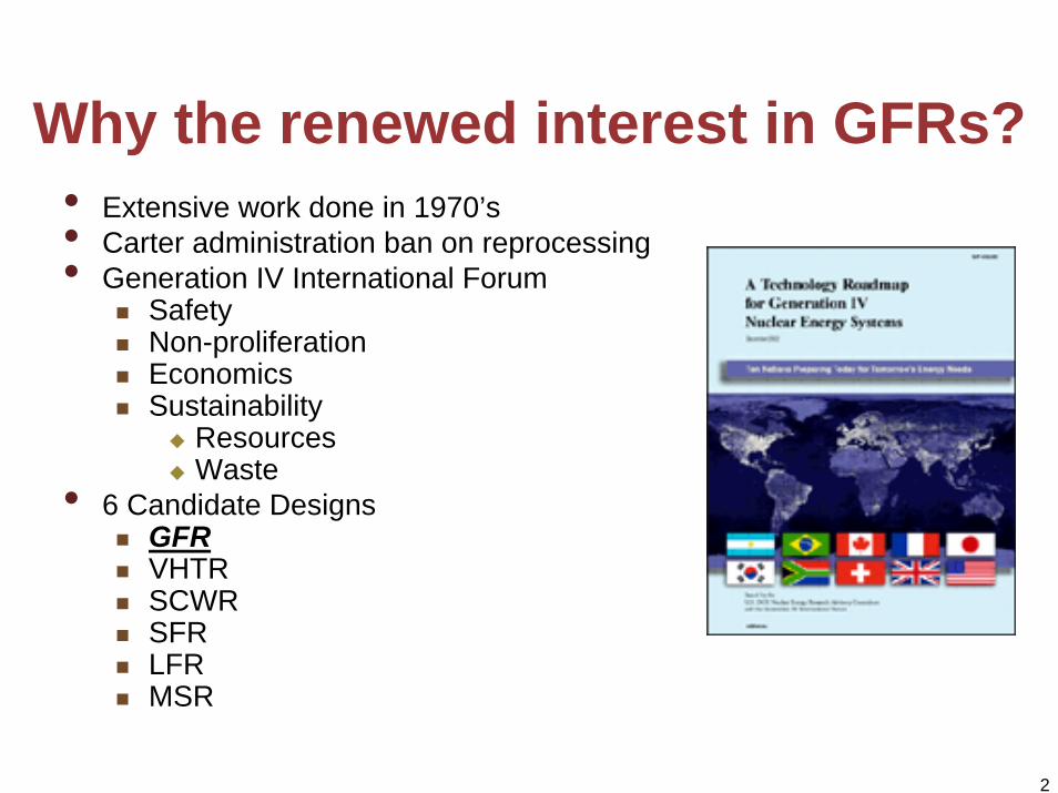
Why the renewed interest in GFRs?• Extensive work done in 1970’s• Carter administration ban on reprocessing• Generation IV International Forum
SafetyNon-proliferationEconomicsSustainability
ResourcesWaste
• 6 Candidate DesignsGFRVHTRSCWRSFRLFRMSR

3
Reactor physics and Gen IV goals
ReactorPhysics
Proliferationresistance
Sustainability-Resources-Waste
Safety
Economy

4
The Engineering Pinwheel
Reactor PhysicsThermal Hydraulics
Safety
Materials
Economics
Regula
tory
Fuel
Per
form
ance
DesignSolution

5
Fast Reactor Fundamentals• The neutrons are fast• No moderator (most of the time)• Coolant is non-moderating
Liquid metalGas
• Neutronic behavior governed mostly by Pu and TRUMuch lower β than LWRs (0.0035 v. 0.0065)
• Shorter prompt neutron lifetime• Tighter lattice than LWRs• A LOCA will insert positive reactivity• MTC not the chief reactivity coefficient of concern as in
LWRs

6
Steady State Reactor Physics Parameters
Parameter Design Philosophy
Power PeakingIntra-assembly, i.e. pin-to-pinRadialAxial
Provide sufficient margin to thermal hydraulic limits
Reactivity limited lifetime Achieve burnups such that the design (1) is cost competitive and (2) has fluence that is not excessive when compared to other options
Isotopic Composition Minimize the volume and radiotoxicity of spent fuel while providing enough Actinide inventory to act as fuel for current and future cycles
Active Reactivity ControlReactivity SwingControl Rod Worth
Keep the reactivity swing low enough such that control rod worth does not become excessive (i.e. significantly beyond current experience, within rod ejection and stuck rod limits)
7
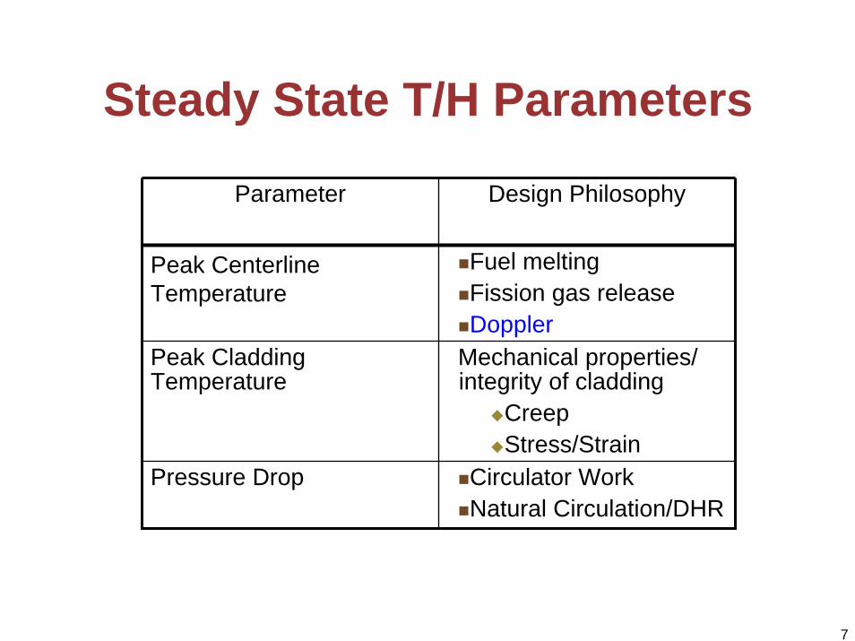
Steady State T/H Parameters
Parameter Design Philosophy
Peak Centerline Temperature
Fuel meltingFission gas releaseDoppler
Peak Cladding Temperature
Mechanical properties/ integrity of cladding
CreepStress/Strain
Pressure Drop Circulator WorkNatural Circulation/DHR

8
The Relation between Rx Physics and T/H Design Constraints
Fuel Geometry(P/D ratio,
fuel pin outer diameter)
Conversion Ratio
Pressure drop Peak Clad Temperature
Isotopic composition
Reactivity Parameters•Reactivity Swing
•Control Rod Worth
Safety parameters•Βeff
•Prompt neutron lifetime•Void reactivity
Peak Fuel Temperature
Thermal Hydraulic Effects
Rx Physics Effects…
9
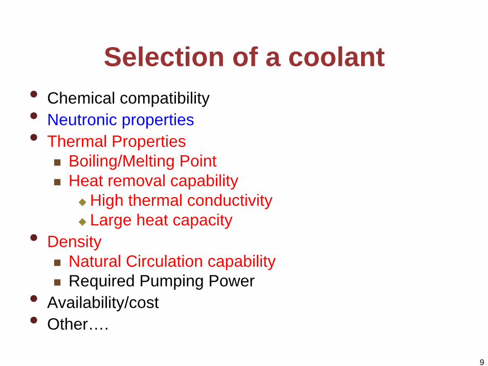
Selection of a coolant• Chemical compatibility• Neutronic properties• Thermal Properties
Boiling/Melting PointHeat removal capability
High thermal conductivityLarge heat capacity
• DensityNatural Circulation capabilityRequired Pumping Power
• Availability/cost• Other….

10
Coolant Case Study: S-CO2
• Power Conversion System (PCS) work begat the neutronics work
High efficiency Brayton cycle (45-50%) v. Rankine(33%)Allows for a direct cycle
• Can provide better natural circulation capability than He• Can do it all at lower temperatures (650oC) than Helium
(850oC)• Requires a higher pressure for Decay Heat Removal and
cycle efficiency (20 MPa v. 8 MPa)What integrated engineering design challenges does this pose?

11
Traditional sodium FBR designs• Large power rating (~3000MWt)• Very high power density
(~300kW/l)To reduce fuel cycle costTo minimize doubling time
• Short doubling time (~25 years)• Oxide fuels - UO2-PuO2 driver
fuel, use of UO2 blankets • Breeding ratio >1 (1.25)• Pool type reactor• Active safety• Intermediate loops• Rankine cycle• Difficult maintenance (opaque
coolant)• Complex and expensive
Diagram of reactor removed due to copyright restrictions.
12
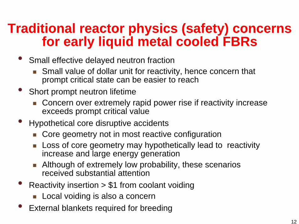
Traditional reactor physics (safety) concerns for early liquid metal cooled FBRs
• Small effective delayed neutron fractionSmall value of dollar unit for reactivity, hence concern that prompt critical state can be easier to reach
• Short prompt neutron lifetimeConcern over extremely rapid power rise if reactivity increase exceeds prompt critical value
• Hypothetical core disruptive accidentsCore geometry not in most reactive configurationLoss of core geometry may hypothetically lead to reactivity increase and large energy generationAlthough of extremely low probability, these scenarios received substantial attention
• Reactivity insertion > $1 from coolant voidingLocal voiding is also a concern
• External blankets required for breeding
13
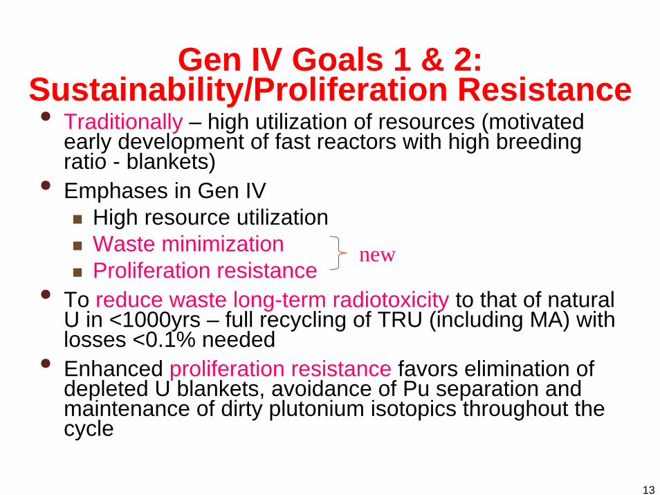
Gen IV Goals 1 & 2: Sustainability/Proliferation Resistance• Traditionally – high utilization of resources (motivated
early development of fast reactors with high breeding ratio - blankets)
• Emphases in Gen IVHigh resource utilizationWaste minimizationProliferation resistance
• To reduce waste long-term radiotoxicity to that of natural U in <1000yrs – full recycling of TRU (including MA) with losses <0.1% needed
• Enhanced proliferation resistance favors elimination of depleted U blankets, avoidance of Pu separation and maintenance of dirty plutonium isotopics throughout the cycle
new

14
Impact of recycling TRUs

15
Sustainability-driven design choices• Use accumulated TRU from spent LWR for 1st FR core • Design GFR with BR=1, no blankets to avoid clean Pu• Recycle TRU without Pu separation, Depleted U feed• If enough GFRs deployed, LWR legacy TRU inventory eliminated• After full transition to GFR, enrichment could be eliminated
LWRLWR Fuel Fabrication
Plant
Conversion &Enrichment Plant
Storage of Depleted U
Nat - UEnriched
U
High -Level Waste Storage
UO2
Reprocessing Plant
U +TRU + FP (1st core)
0.1% TRU loss + FPs
U +TRU + FP
Depleted U
GFR
Storage of LWR spent fuel
U +TRU
Today
GFR for both waste management and resource utilization

16
Consequences of sustainability-driven choices
• Small effective delayed neutron fraction
TRUs have small βTRUs in LWR spent fuel 49%Pu239, 23%Pu240, 7%Pu241, 6.6%Np237, 5%Pu242, 4.7%Am241, 2.7%Pu238Smaller margin to superprompt criticality, hence reactor control more challengingWhat can be done to increase βeff?
Not muchHarden spectrum to fission more U238, but this worsens coolant void worthIncrease leakage, but this hurts neutron economy
Graph removed due to copyright restrictions.

17
Consequences of sustainability-driven choices (Cont’)
• Increased positive coolant void worthSafety issueTypically much smaller in GFR than in LMRsCan be fastSmaller β makes coolant void worth larger in terms of reactivity in dollarsMore positive coolant void worth is due to TRU loading (primarily Pu239, Np237 and Am241)Why?

18
Neutron spectrum in GFR
10-4 10-3 10-2 10-1 100 101
0.00
0.01
0.02
0.03
0.04 CO2-cooled, Zr matrix UZr fuel Na cooled, TRU fuel LBE-cooled, TRU fuel
Nor
mal
ized
frac
tion
of n
eutro
ns in
ene
rgy
grou
p
Energy (MeV)

19
Positive coolant void worth in FRsThree components of coolant void worth
1. Spectrum hardening
Pu239 capture and fission cross sections
CaptureFission
•Neutron population shifts•Spectrum hardening•Fission/capture ratio increases•Reactivity increases
Major neutronpopulation
20
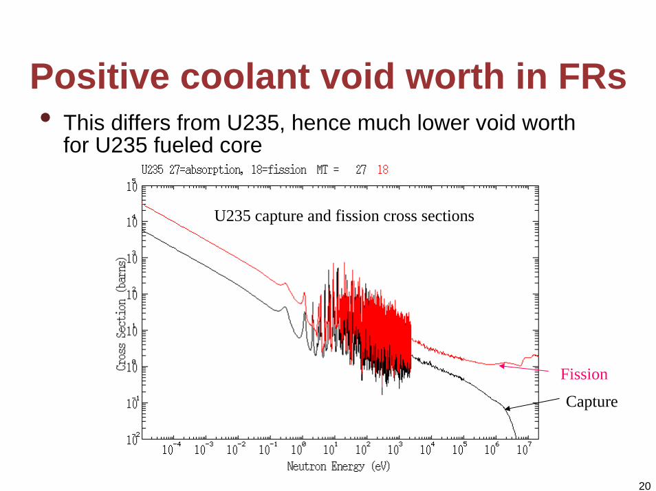
Positive coolant void worth in FRs• This differs from U235, hence much lower void worth
for U235 fueled core
U235 capture and fission cross sections
Capture
Fission
21
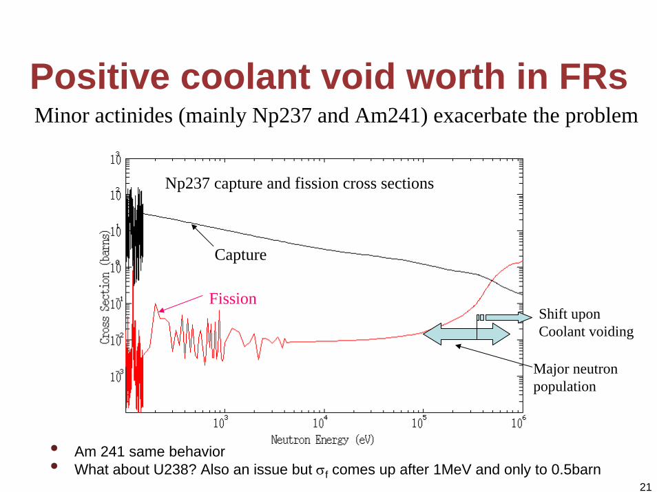
Positive coolant void worth in FRs
• Am 241 same behavior• What about U238? Also an issue but σf comes up after 1MeV and only to 0.5barn
Minor actinides (mainly Np237 and Am241) exacerbate the problem
Np237 capture and fission cross sections
Capture
Fission
Major neutronpopulation
Shift upon Coolant voiding
22
Positive coolant void worth in FRs (cont)2. Coolant absorption
Less coolant → smaller parasitic absorption, hence reactivity increases (same for over-moderated LWRs)Small for GFR but can be significant for LMRs –coolants with higher absorption cross section worse
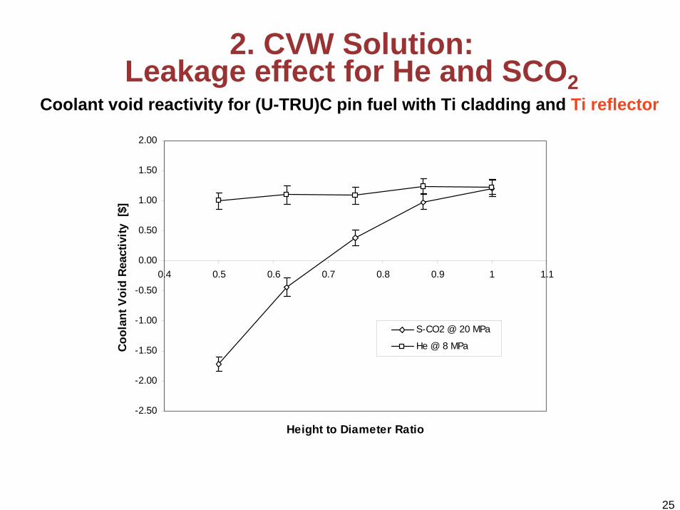
3. Neutron leakageLess coolant → increased neutron leakage, hence reduced reactivitySmaller or pancake cores have lower coolant void worth Coolants with larger scattering cross section have larger reactivity reduction from leakage

23
Ways to reduce CVW in GFRs• Although CVW is small (in comparison to LMRs), its reduction is difficult.
Why? • Leakage component is very small (negligible for some gases, such as He)• Possibilities:
1. Use core and reflector materials that exhibit an increase in absorption cross section/reduction in reflection upon spectrum hardening
2. Use gas that has high scattering macroscopic cross section to increase benefit of leakage effect
3. Minimize coolant fraction in the core4. Soften the spectrum

24
1. CVW solution: Titanium reflector
Ti capture and scattering cross sections
Scattering xs
Absorption xs
This would be nice core material but nature does not provide such
25
2. CVW Solution: Leakage effect for He and SCO2
Coolant void reactivity for (U-TRU)C pin fuel with Ti cladding and Ti reflector
-2.50
-2.00
-1.50
-1.00
-0.50
0.00
0.50
1.00
1.50
2.00
0.4 0.5 0.6 0.7 0.8 0.9 1 1.1
Height to Diameter Ratio
Coo
lant
Voi
d Re
activ
ity [
$]
S-CO2 @ 20 MPa
He @ 8 MPa

26
3. CVW solution: Tube-In-Duct (TID) Fuel Assembly
• Hexagonal duct with coolant tubes• Compatible with vibrationally
compacted (VIPAC) or specially formed “hexnut” pellet fuel
• Vented to reduce pressure-induced stresses in cladding and duct wall (as in GCFR of 1970’s)
• Very high fuel volume fraction (~63%) with tolerable core pressure drop.
Coolant Channels
Cladding(ODS MA956)
Duct Wall
Fuel
(Horizontal Cross Section)
Courtesy of CEA Cadarache. Used with permission.

27
4. CVW solution: Use of diluent to soften spectrum
VOIDEDf
c
UNVOIDEDf
cVOID ⎟
⎟⎠
⎞⎜⎜⎝
⎛−⎟
⎟⎠
⎞⎜⎜⎝
⎛Δ
σσ
σσαρ

28
Neutron Energy Spectra of Fuel with BeO Diluent
0.00E+00
5.00E-03
1.00E-02
1.50E-02
2.00E-02
2.50E-02
1.00E-05 1.00E-04 1.00E-03 1.00E-02 1.00E-01 1.00E+00 1.00E+01
Ene r gy ( M e V)
Normalized Spect rum - 10% BeO Normalized Spect rum - 20% BeO Normalized Spect rum - 30% BeO
Normalized Spect rum - 40% BeO Normalized Spect rum - 50% BeO Normalized Spect rum - No BeO

29
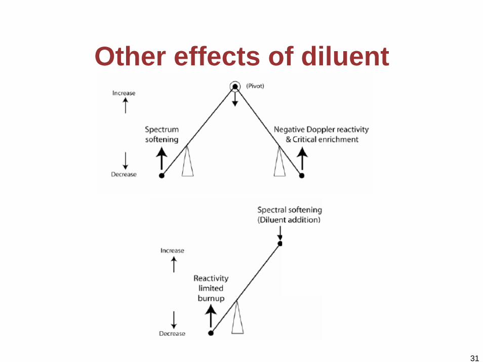
The Diluent Approach• Without diluent, enrichment zoning
BOL CVW=1.6$, radial peaking =1.56• With BeO diluent, enrichment and diluent zoning
BOL CVW=0.5$, radial peaking =1.15• Diluent can also reduce axial peaking• Shapes power by:
Displacing fuelMinor effect
Softening neutron energy spectrumReduces neutron energy below fast fission thresholdDominant effect
• BeOModerating effectThermal conductivity enhancementBest CVR reduction among candidate options
• Other candidatesSiCTiC

30
Radial Power Shaping Using BeO
31
Other effects of diluent

32
Consequences of sustainability-driven choices (Cont’)
• Difficult to achieve conversion ratio (CR) of 1.0 in the absence of blankets
Balance between leakage/neutron economy and CVWBalance thermal hydraulics and neutronics through coolant and fuel volume fractions
33
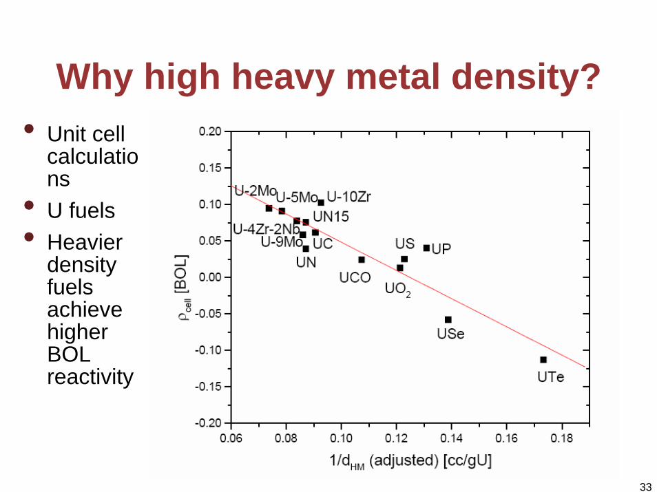
Why high heavy metal density?• Unit cell
calculations
• U fuels• Heavier
density fuels achieve higher BOL reactivity

34
• Indirect link Capital cost via safety - examples
Reduced peaking allows higher power density for given structural material temperature limits, hence more energy from the same vessel and lower costLow reactivity swing reduces number of control rods (CRDs expensive)
• Direct linkFuel cycle cost
Strive for low enrichment (TRU weight fraction)Strive for high specific power
Gen IV Goals 3: Economy

35
Example of long life, low power density design • Synergistic twin to thermal GT-
MHR• Same low power density – 8kW/l• Passive decay heat removal by
conduction and radiation • Excellent safety• Neutronically feasible • Very long core life – 50 years
0 20 40 60 800.96
0.98
1.00
1.02
1.04K
eff
Effective full power years
Active core
reflectorInner reflector
Shield
0 50 100 150 200 250400
600
800
1000
1200
1400
Tem
pera
ture
(C)
Time (hours)

36
0
5
10
15
20
25
0
20
40
60
80
100
120
0 20 40 60 80 100 120
FCC-PWR(4%)FCC-GCRF(13%)
T-PWRT-GCFR
Fuel
Cyc
le c
ost (
mill
s/kW
hr)
Core residence tim
e for fixed burnup
Specific power (kW/kgHM)
Bd=50MWd/kg
Bd=180MWd/kg
But very high fuel cycle cost!!!
•Twin to MHR-GT not economically feasible•Specific power should not be much below 20kW/kg, Shoot for 25kW/kgHM (BWR)•SUPERSAFE reactor of no use without a buyer•What works for thermal reactor may not work for fast reactor
xTe1xT
TpL766.8CFCC −−
=η
•For U235 enriched fuel•η=45%, L=0.90 •Bd=180MWd/kgHM•discount rate x=10%/yr•C=3936 $/kg for e=13%
•η=33%, L=0.90 •Bd=50MWd/kgHM•discount rate x=10%/yr•C=1200 $/kg for e=4.5%•Fabrication 200$/kg•SP=38kW/kgHM
GFR
PWR
FCC-PWR (4%)FCC-GCFR (13%)
40
2.5

37
• Reactivity increase from coolant depressurization• Primary issue is post LOCA decay heat removal
Gen IV emphasis is on enhanced safetyCurrent trend – rely on passive means
Gen IV Goals 4: Safety

38
GFR with natural circulation decay heat removal at elevated pressure
•4x50% cooling loops•after depressurization of primary system, containment pressure increases and provides elevated pressure needed for natural circulation
Low pressure drop core, hence large coolant volume fraction –but neutronics favors small coolant volume fractions
Emergency cooling Heat Exchanger
reflector
Core
Hexagonal blocks with coolant channels
Guard containment
Water cooling
Reactor vessel
Requires
39
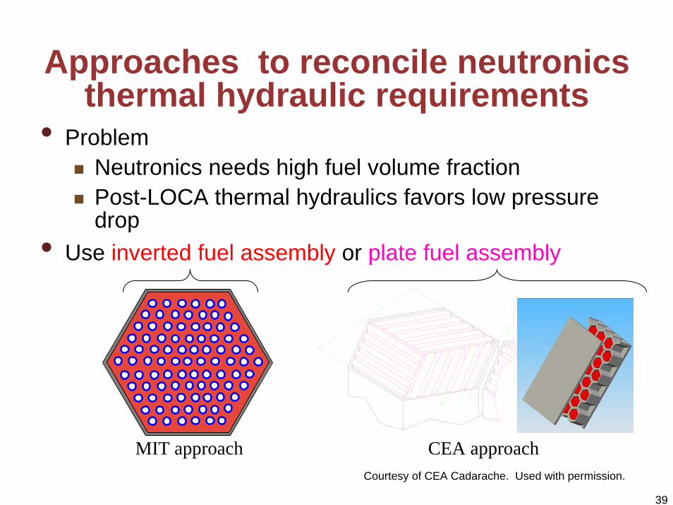
Approaches to reconcile neutronicsthermal hydraulic requirements
• ProblemNeutronics needs high fuel volume fractionPost-LOCA thermal hydraulics favors low pressure drop
• Use inverted fuel assembly or plate fuel assembly
MIT approach CEA approachCourtesy of CEA Cadarache. Used with permission.

40
Neutronic Design for Safety• Most GFRs have slightly positive CVW• Is this acceptable?• How to assure safety with slightly positive CVW?
Rely on other reactivity coefficients, which are negative
Doppler feedbackFuel thermal expansion coefficientCore radial expansion coefficientCRD driveline expansions coefficient
Strive for a design with such a combination of reactivity coefficients that can achieve reactor shutdown without exceeding structural materials and fuel temperature limits

41
Possible Safety Approach• Follow IFR approach of reactor self-controllability• Goal: reactor should have sufficiently strong passive
regulation of power to compensate for operator errors or equipment failures even if the scram fails.
• Core designed such that it inherently achieves safe shutdown state without exceeding temperature limits that would lead to core or vessel damage
• This must be achieved under the most restricting anticipated transients without scram (ATWS)
Unprotected (without scram) loss of flow (ULOF)Unprotected loss of heat sink (ULOHS)Unprotected overpower (UTOP) –
largest worth CRD withdrawal

42
Possible Safety Approach (cont’)• Note that this is much stronger requirement than for
LWRs• Loss of coolant is not credible in IFR since coolant
under no pressure and if vessel fails, the coolant remains in guard vessel (but it is an issue in GFR, hence it needs to be accommodated)
• Inherent shutdown is determined by:
• Need to find such combination of reactivity feedbacks and limits that makes it possible to achieve self-controllability
Reactivity feedbacksMaterial and coolant-related limits (e.g., clad, boiling, freezing T for IFR)

43
Safety Approach (cont’)• Quasi-static balance for reactivity encompassing all paths that affect
reactivity is
• Since time constants of heat flow changes and temperature induced geometry changes and of delayed neutrons are in the range of half second to several minutes, and transients are slower, most feedbacks are linear permitting above equation to be represented as
externaltempflowpower ρρρρ Δ+Δ+Δ+Δ=0
P,F – power and coolant flow normalized to full power and flowδTin – change from normal coolant temperatureA,B,C – integral reactivity parameters that arise from temperature and
structural changes - discussed nextThree criteria for A,B,C can be derived to achieve self-controllability
externalinletCTBFPAP ρδρ Δ++−+−=Δ= )1/()1(0
CVWρΔ+ for GFR
for GFRCVWρΔ+
Wade and Chang, “The IFR Concept Physics of Operation and Safety, Nucl. Sci. Eng., Vol. 100, p. 507, 1988

44
Self-controllability criteria for LMRs• ABR – fertile free, lead cooled actinide burner• LMRs can be designed to satisfy these criteria in spite of positive CVW• Transient calculations still needed to confirm the performance
criterionS1: A/B
1.0
2.0
IFRABR
IFR ABR
S2: CΔTc/BControls Tc rise in ULOFs Balance between ULOHs
and chilled Tinlet
S3: ΔρTOP / |B|
IFR ABR
Controls UTOP
Limits Actual values

45
GFR self controllability • Designing a GFR with self controllability is a challenge• Differences
Additional term in reactivity balance to account for CVW Direct cycle – separate ULOHS and ULOF may not be possible – loss of heat sink (precooler) may lead to loss of flow to prevent compressor surge or stall, hence ULOF and ULOHS will be always combinedSelf-controllability criteria need to be updatedDecay heat removal may not be fully passive
• IssuesMIT design with UO2 fuel has too large Doppler feedback (low conductivity, softer spectrum)

46
Questions

47
Extra Slides

48
Natural circulation performance - CO2 and He
0.0 0.2 0.4 0.6 0.8 1.0 1.2 1.4100
200
300
400
500
600
700
800
900
1000
1100
1200
1300
P = 5.0 barsmdot = 78.97 kg/s
Tem
pera
ture
(o C)
Core Axial Location (m)
Average Channel Coolant Average Channel Wall Hot Channel Coolant Hot Channel Wall
Post LOCA core temperature profiles
0.0 0.2 0.4 0.6 0.8 1.0 1.2 1.40
100
200
300
400
500
600
700
800
900
1000
1100
1200
1300
P = 13 barsmdot = 13.87 kg/s
Average Channel Coolant Average Channel Wall Hot Channel Coolant Hot Channel Wall
Tem
pera
ture
(o C)
Core Axial Location (m)
CO2 Helium•Limits – peak cladding temperature=1200°C, maximum core-average outlet T=850°C•2% decay heat can be removed by natural circulation•CO2 much better than He – requires backup pressure of 5bars versus 13 bars for He•Helium – issue of excursion type instabilities

49
IFR criteria for passive self-regulation
• A-net power reactivity coefficient (Doppler, fuel thermal expansion)A=(αd+ αth) ΔTf [¢]
• B-power/flow coefficient of reactivity - controls asymptotic temperature rise in ULOF (coolant density, CRD-driveline, core radial expansion coefficients B = [αd+ αth+ αden +2(αcrd + 2/3αrad)] ΔTc/2 [¢]
• Key strategies:
• Large B also favors large temperature rise across the core• But penalties on efficiency, hence compromise needed
S1-criterion A/B < 1.0; A,B negative
Small negative A - metallic fuel, hard spectrumLarge negative B - minimize coolant density coefficient

50
IFR criteria for passive self-regulationS2-criterion 1.0<(C ΔTc/B) < 2.0; C negative
• C –inlet temperature coef. of reactivity • provides balance between the ULOHS and the chilled inlet
temperature inherent response (Doppler, fuel thermal exp., coolant density core, radial exp.) C= (αd+ αth+ αden + αrad) [¢/K]
• range comes from cladding limit and coolant temperature rise
• Main efforts:
[ ]inT/∂ρΔ∂−=
Minimize coolant density coefficientIncrease core radial expansion coefficient, if needed
51
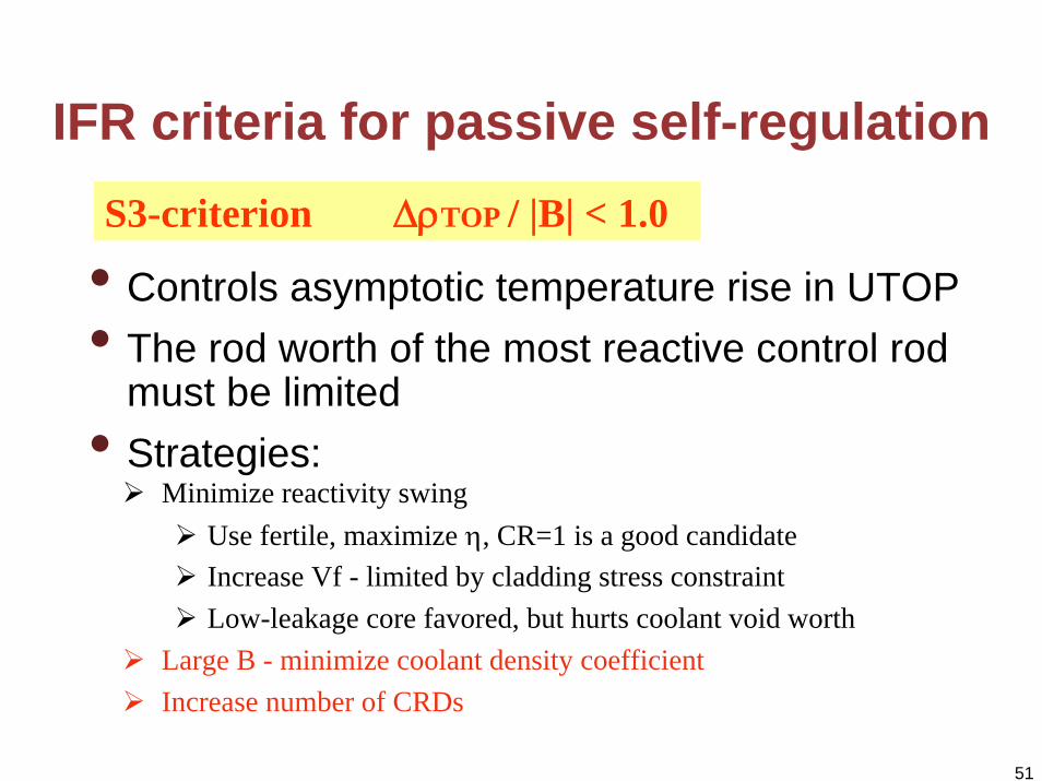
IFR criteria for passive self-regulation
• Controls asymptotic temperature rise in UTOP • The rod worth of the most reactive control rod
must be limited• Strategies:
S3-criterion ΔρTOP / |B| < 1.0
Minimize reactivity swingUse fertile, maximize η, CR=1 is a good candidateIncrease Vf - limited by cladding stress constraintLow-leakage core favored, but hurts coolant void worth
Large B - minimize coolant density coefficientIncrease number of CRDs

52
Feasibility domain for plate core at 50kW/l• Feasibility domain for carbide CERCER (50/50) 2400MWth core q’’’= 50W/cc
CEA results
Core design possible
Courtesy of CEA Cadarache. Used with permission.

53
Feasibility domain for plate core at 100kW/l• Feasibility domain for carbide CERCER (50/50) 2400MWth core q’’’= 100W/cc
CEA results
Courtesy of CEA Cadarache. Used with permission.
54
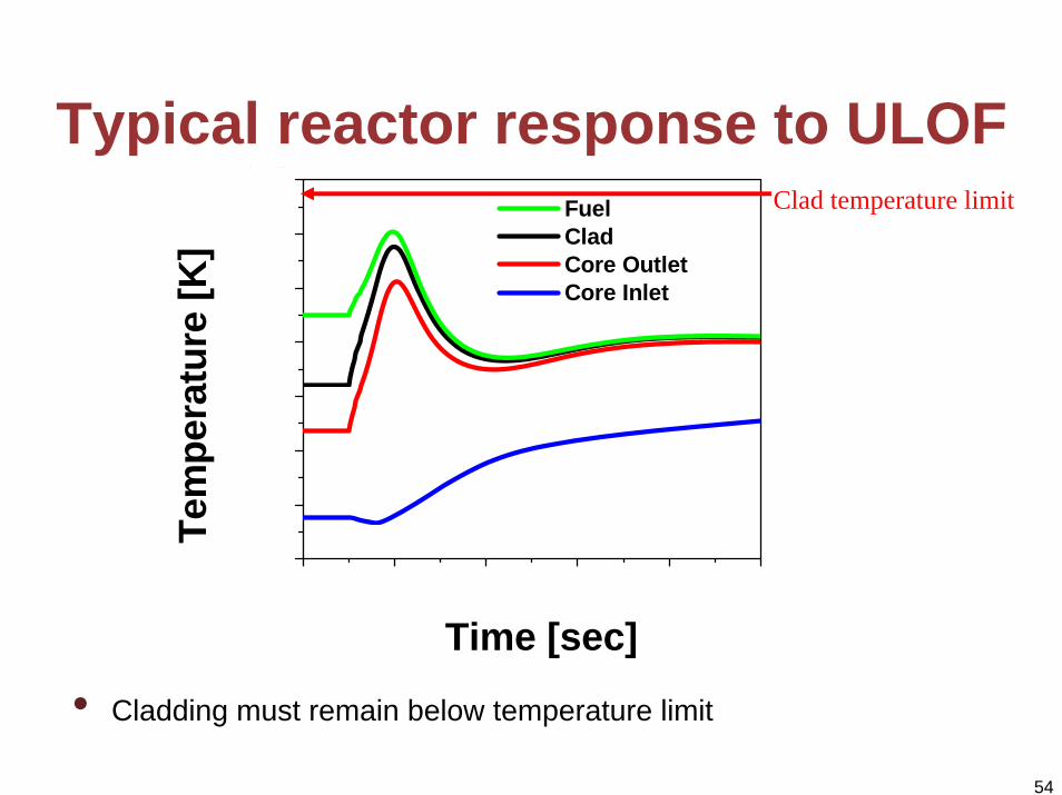
Typical reactor response to ULOF
400 600 800 1000 1200 140
• Cladding must remain below temperature limit
0700
750
800
850
900
950
1000
1050 Fuel Clad Core Outlet Core Inlet
Tem
pera
ture
[K]
Time [sec]
Clad temperature limit
55
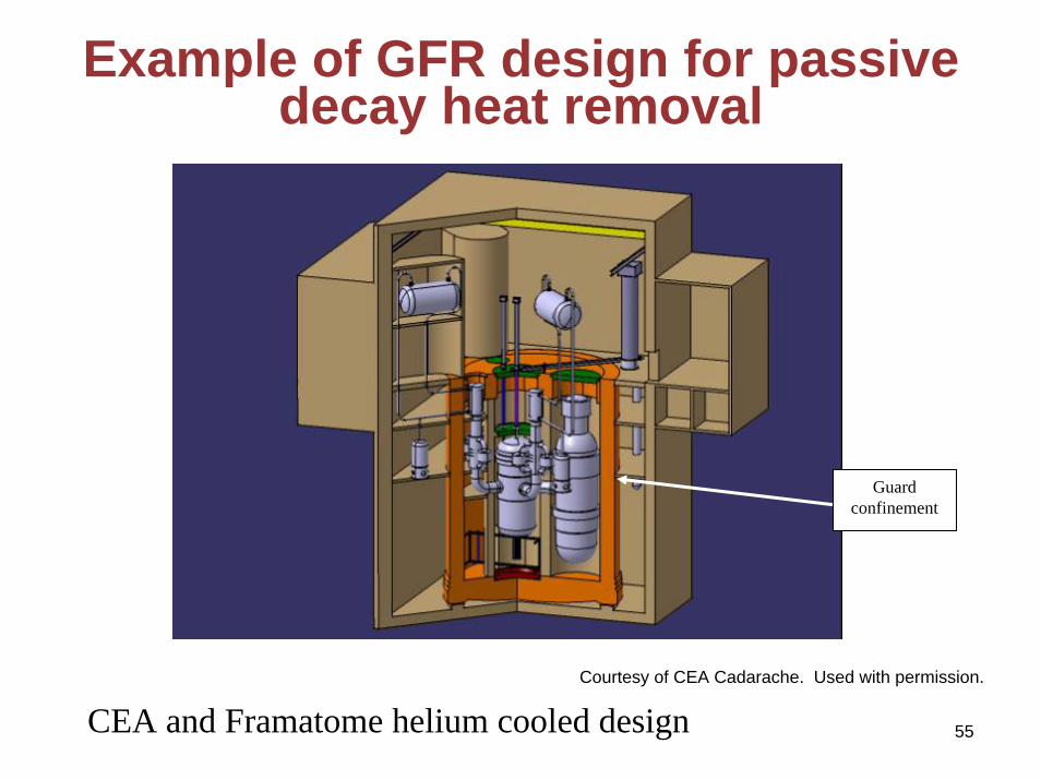
Example of GFR design for passive decay heat removal
CEA and Framatome helium cooled design
Guardconfinement
Courtesy of CEA Cadarache. Used with permission.

56
Example – neutronic data for CEA design
Courtesy of CEA Cadarache. Used with permission.
57
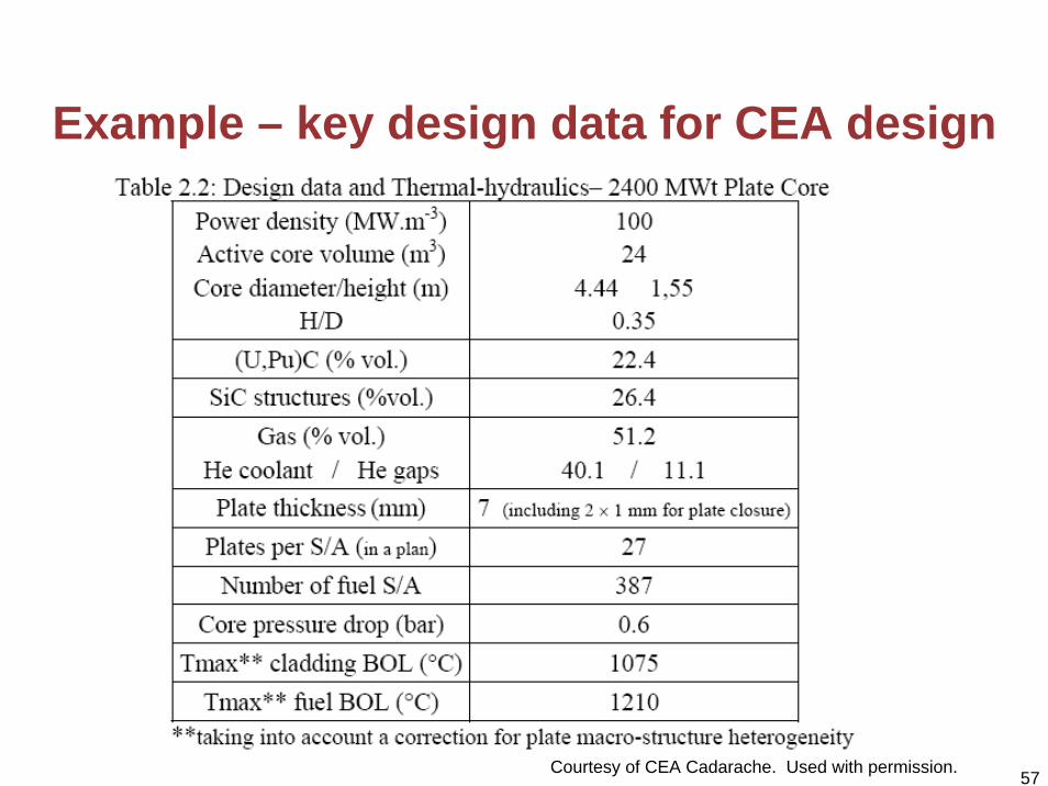
Example – key design data for CEA design
Courtesy of CEA Cadarache. Used with permission.