read - iapmo group california mechanical code/chapter 03.pdf · 325.1 x x 325.2 x x 325.3 x 326.0 x...
TRANSCRIPT

432013 CALIFORNIA MECHANICAL CODE
CALIFORNIA MECHANICAL CODE – MATRIX ADOPTION TABLECHAPTER 3 – GENERAL REQUIREMENTS
(Matrix Adoption Tables are non-regulatory, intended only as an aid to the user. See Chapter 1 for state agency authority and building application.)
Adopting Agency BSC SFMHCD DSA OSHPD
BSCC DPH AGR DWR CA SL SLC1 2 1-AC AC SS SS/CC 1 2 3 4
Adopt Entire Chapter X X X
Adopt Entire Chapter as amended(amended sections listed below) X X X X X X X
Adopt only those sections that arelisted below
Chapter/Section
303.3, Exception 2 X X X X
303.8 X X X
303.8.1 X X
315.0 X X X X
323.0 X X X
324.1 X X
324.2 X X
325.1 X X
325.2 X X
325.3 X
326.0 X X X X
Table 325 X X X X
READ ONLY

44 2013 CALIFORNIA MECHANICAL CODE
READ ONLY

301.0 General.301.1 Applicability. This chapter covers general require-ments for heating, ventilating, air-conditioning, refrigeration,miscellaneous heat-producing, and energy-utilizing equip-ment. Such equipment shall conform to the requirements ofthis code.
Equipment shall not be installed or altered in violationof this code, nor shall the fuel input rate to equipment beincreased in excess of the approved British thermal unit perhour (Btu/h) (kW) rating at the altitude where it is being used.
Defective material or parts shall be replaced in such amanner as not to invalidate an approval.
302.0 Approval.302.1 How Obtained. Each appliance shall be approved bythe Authority Having Jurisdiction for safe use or comply withapplicable nationally recognized standards as evidenced bythe listing and label of an approved agency. A list of acceptedstandards is included in Chapter 17.302.2 Complying Design of Equipment. Installers shallfurnish satisfactory evidence that the appliance is constructedin accordance with the requirements of this code. The perma-nently attached label of an approved agency shall bepermitted to be accepted as such evidence.302.3 Oil-Burning Appliances. The tank, piping, and valvesfor appliances burning oil shall be installed in accordancewith the requirements of NFPA 31.
303.0 Installation.303.1 Installation Practices. Mechanical systems shall beinstalled in a manner in accordance with this code, applicablestandards, and the manufacturer’s installation instructions. 303.2 Listed Appliances. Except as otherwise provided inthe code, the installation of appliances regulated by this codeshall be in accordance with the conditions of listing. Theappliance installer shall leave the manufacturer’s installationand operating instructions attached to the appliance. Clear-ances of listed appliances from combustible materials shallbe as specified in the listing or on the rating plate.303.3 Room Large in Comparison to Size of Equipment.Central-heating furnaces not listed for closet or alcove instal-lation shall be installed in a room or space having a volumenot less than 12 times the total volume of the furnace; central-heating boilers not listed for closet or alcove installation shallbe installed in a room or space having a volume 16 times thevolume of the boiler. [OSHPD 1, 2, 3 & 4] The total volumeof the boilers shall be based on the total number of central-heating boilers that can operate at the same time.
Exceptions:(1) The installation clearances for furnaces and boilers in
rooms not large in comparison with the size of the equip-ment shall be as specified in the appliance listing regard-less of whether the enclosure is of combustible ornoncombustible materials and shall not be reduced by theprotection methods described in Table 303.3(1) or anyother method.
(2) [OSHPD 1, 2, 3 & 4] A 25 percent reduction in the boilerroom volume is allowed with forced-draft boilers andapproved ventilation of the boiler room. In no case shallboiler room volume or clearances be reduced belowthose required by the conditions of the boiler listing. Theboiler and the boiler room ventilation system, includingfans, controls, and damper motors shall be on emergencypower when required by Section 326.0. The ventilationsystem shall either operate continuously, or, if inter-locked with the boiler(s) it shall not interfere with theproper boiler operation.Where the ceiling height of the room or space exceeds 8
feet (2438 mm), the volume shall be calculated on the basisof an 8 foot (2438 mm) height.303.4 Unlisted Appliances. Unlisted appliances shall beinstalled with the standard clearances from combustibleconstruction specified in Table 303.4. Unlisted appliancesshall have the standard clearances of Table 303.4 reduced byemploying the forms of protection specified in Table303.3(1). Forms of protection specified in Table 303.3(1)shall be permitted to be utilized to reduce clearances tocombustible construction for applicable appliances.303.5 Anchorage of Appliances.Appliances designed to befixed in position shall be securely fastened in place in accor-dance with the manufacturer’s installation instructions.Supports for appliances shall be designed and constructed tosustain vertical and horizontal loads within the stress limita-tions specified in the building code.303.6 Movement. Movement of appliances with casters shallbe limited by a restraining device installed in accordance withthe connector and appliance manufacturer’s installationinstructions.303.7 Identification of Equipment. Where more than oneheating, cooling, ventilating, or refrigerating system isinstalled on the roof of a building or within a building, it shallbe permanently identified as to the area or space served bythe equipment.303.8 Liquefied Petroleum Gas Facilities. Containers,container valves regulating equipment, and appurtenances forthe storage and supply of liquefied petroleum gas shall beinstalled in accordance with NFPA 58 and the California FireCode.
452013 CALIFORNIA MECHANICAL CODE
CHAPTER 3GENERAL REQUIREMENTS
READ ONLY

303.8.1 Liquefied Petroleum Gas Appliances. [HCD 1 &HCD 2] Liquefied petroleum gas-burning appliances shallnot be installed in a pit, basement, or similar locationwhere heavier-than-air gas might collect. Appliances sofueled shall not be installed in an above-grade under-floorspace or basement unless such location is provided withan approved means for removal of unburned gas.
303.9 Equipment on Roofs. Equipment on roofs shall bedesigned or enclosed so as to withstand climatic conditions inthe areas in which it is installed. Where enclosures areprovided, each enclosure shall be of reasonable height, andshall have not less than a 30 inch (762 mm) clearance betweenthe entire service access panel(s) of the equipment and thewall of the enclosure. [NFPA 54:9.4.1.1]
303.9.1 Roof Support. Roofs on which equipment is tobe installed shall be capable of supporting the additionalload or shall be reinforced to support the additional load.[NFPA 54:9.4.1.2]303.9.2 Corrosion Resistance. Access locks, screws,and bolts shall be of corrosion-resistant material. [NFPA54:9.4.1.3]303.9.3 Roof Drainage and Rails. Equipment shall beinstalled on a well-drained surface of the roof. Not lessthan 6 feet (1829 mm) between a part of the equipmentand the edge of a roof or similar hazard, or rigidly fixedrail, guards, parapets, or other building structures not lessthan 42 inches (1067 mm) in height shall be provided onthe exposed side. [NFPA 54:9.4.2.2]303.9.4 Electrical Power. Equipment requiring anexternal source of electrical power for its operation shallbe provided with the following:(1) Readily accessible electrical disconnecting means
within sight of the equipment. (2) A 120 VAC grounding-type receptacle outlet on the
roof adjacent to the equipment. The receptacle outletshall be on the supply side of the disconnect switch.[NFPA 54:9.4.2.3]
304.0 Service and Access to Equipment and Appliances.304.1 General. Equipment and appliances shall be accessiblefor inspection, service, repair, and replacement withoutremoving permanent construction. Clearance shall be main-tained to: (1) Clean heating surfaces.(2) Replace filters, blowers, motors, burners, controls, and
vent connections.(3) Lubricate moving parts. (4) Adjust and clean burners, pilots, and the proper func-
tioning of explosion vents, where provided. [NFPA54:9.2.1]Unless otherwise specified, not less than 30 inches (762
mm) in depth, width, and height of working space shall beprovided.Exception: Unit heaters and room heaters shall be permittedto be installed with an 18 inches (457 mm) minimum depthworking space. A platform shall not be required for unit
heaters or room heaters. The operating instructions shall beattached to the appliance where they are capable of being readeasily.304.2 Access to Equipment and Appliances on Roofs.Appliances located on roofs or other elevated locations shallbe accessible. [NFPA 54:9.4.3.1]
304.2.1 Access from Inside. Buildings exceeding 15 feet(4572 mm) in height shall have an inside means of accessto the roof, unless other means acceptable to the AuthorityHaving Jurisdiction are used. [NFPA 54:9.4.3.2]
304.2.1.1 Door or Scuttle. The inside means ofaccess shall be a permanent or foldaway insidestairway or ladder, terminating in an enclosure,scuttle, or trap door. Such scuttles or trap doors shallbe not less than 22 inches by 24 inches (559 mm by610 mm) in size, shall open easily and safely underall conditions, especially snow, and shall beconstructed so as to permit access on the inside.
Not less than 6 feet (1829 mm) of clearanceshall be between the access opening and the edge ofthe roof or similar hazard, or rigidly fixed rails orguards not less than 42 inches (1067 mm) in heightshall be provided on the exposed side. Where para-pets or other building structures are utilized in lieu ofguards or rails, they shall be not less than 42 inches(1067 mm) in height. [NFPA 54:9.4.3.3]304.2.1.2 Permanent Ladders. Permanent laddersrequired by Section 304.2.1.1 shall be constructedin accordance with the following:(1) Have side railings which extend not less than 30
inches (762 mm) above the roof or parapet wall.(2) Landings shall not exceed 18 feet (5486 mm)
apart measured from the finished grade.(3) Width shall be not less than 14 inches (356 mm)
on center.(4) Rungs shall not exceed 14 inches (356 mm) on
center.(5) Toe space shall be not less than 6 inches (152
mm).304.2.2 Permanent Lighting. Permanent lighting shallbe provided at the roof access. The switch for suchlighting shall be located inside the building near theaccess means leading to the roof. [NFPA 54:9.4.3.4]304.2.3 Standing Water.Where water stands on the roofat the equipment, in the passageways to the equipment,where the roof is of a design having a water seal, a plat-form, walkway, or both shall be provided above thewaterline. Such platform(s) or walkway(s) shall belocated adjacent to the equipment and control panels sothat the equipment is capable of being safely servicedwhere water stands on the roof. [NFPA 54:9.4.2.4]
305.0 Automatic Control Devices.305.1 General. Heating appliances shall be equipped with alisted device or devices that will shut off the fuel supply to the
46
GENERAL REQUIREMENTS
2013 CALIFORNIA MECHANICAL CODE
READ ONLY

main burner or burners in the event of pilot or ignition failure.Liquefied petroleum gas-air-burning heating appliances shallbe equipped with a listed automatic device or devices that willshut off the flow of gas to the pilot in the event of ignitionfailure.Exception: The listed shutoff devices shall not be requiredon range or cooking tops, log lighters, lights, or otheropen-burner manually operated appliances, or listed appli-ances not requiring such devices and specific industrial appli-ances as approved by the Authority Having Jurisdiction.
Heating appliances whose manual fuel controls are notreadily accessible from the main portion of the building beingheated shall be equipped with remote controls.
Forced-air and gravity-type warm air furnaces shall beequipped with a listed air outlet temperature limit control thatcannot be set for temperatures exceeding 250˚F (121˚C). Suchcontrols shall be located in the bonnet or plenum, within 2feet (610 mm) of the discharge side of the heating element ofgravity furnaces or in accordance with the conditions oflisting.
Electric duct heaters shall be equipped with an approvedautomatic reset air outlet temperature limit control that willlimit the outlet air temperature to not exceed 200°F (93°C).The electric elements of the heater shall be equipped withfusible links or a manual reset temperature limit control thatwill prevent outlet air temperature in excess of 250°F (121°C).
306.0 Standards.306.1 General. Standards listed or referred to in this chapteror other chapters cover materials that will conform to therequirements of this code, where used in accordance with thelimitations imposed in this or other chapters thereof and theirlisting. Where a standard covers materials of various grades,weights, quality, or configurations, the portion of the listedstandard that is applicable shall be used. Design and mate-rials for special conditions or materials not provided forherein shall be permitted to be used by special permission ofthe Authority Having Jurisdiction after the Authority HavingJurisdiction has been satisfied as to their adequacy. A list ofaccepted mechanical material standards is included in Table1701.0.
307.0 Labeling.307.1 Marking. Each length of pipe and each pipe fitting,material, and device used in a mechanical system shall havecast, stamped, or indelibly marked on it the manufacturer’smark or name, which shall readily identify the manufacturerto the end user of the product. Where required by theapproved standard that applies, the product shall be markedwith the weight and the quality of the product. Materials anddevices used or entering into the construction of mechanicalsystems, or parts thereof, shall be marked and identified in amanner satisfactory to the Authority Having Jurisdiction.Such marking shall be done by the manufacturer. Field mark-ings shall not be acceptable.
307.2 Fuel-Burning Appliances. Fuel-burning heating appli-ances shall bear a permanent and legible factory-appliednameplate on which shall appear:(1) The manufacturer’s name.(2) The approved fuel input rating of the appliance,
expressed in Btu/h (kW).(3) The model and serial number.(4) Instructions for the lighting, operation, and shutdown of
the appliance.(5) The type of fuel approved for use with the appliance.(6) The symbol of an approved agency certifying compli-
ance of the equipment with recognized standards.(7) Required clearances from combustible surfaces on which
or adjacent to which it is permitted to be mounted.307.3 Electric Heating Appliances. Electric heating appli-ances shall bear a permanent and legible factory-appliednameplate on which shall appear:(1) The name or trademark of the manufacturer.(2) The catalog (model) number or equivalent.(3) The electrical rating in volts, amperes (or watts), and for
other than single phase, the number of phases.(4) The output rating in Btu/h (kW).(5) The electrical rating in volts, amperes, or watts of each
field-replaceable electrical component.(6) The symbol of an approved agency certifying compli-
ance of equipment with recognized standards.(7) Required clearances from combustible surfaces on which
or adjacent to which it is permitted to be mounted.An appliance shall be accompanied by clear and
complete installation instructions, including required clear-ances from combustibles other than mounting or adjacentsurfaces, and temperature rating of field-installed wiringconnections exceeding 140°F (60°C).307.4 Heat Pump and Electric Cooling Appliances. Heatpumps and electric cooling appliances shall bear a permanentand legible factory-applied nameplate on which shall appear:(1) The name or trademark of the manufacturer.(2) The catalog model nomenclature.(3) The amount and type of refrigerant.(4) The factory test pressures or pressures applied.(5) The electrical rating in volts, amperes, and for other than
single phase, the number of phases.(6) The output rating in Btu/h (kW).(7) The electrical rating in volts, amperes, or watts of each
field replaceable electrical component.(8) The symbol of an approved agency certifying compli-
ance of the equipment with recognized standards.(9) Required clearances from combustible surfaces on which
or adjacent to which it is permitted to be mounted.An appliance shall be accompanied by clear and
complete installation instructions, including required clear-
47
GENERAL REQUIREMENTS
2013 CALIFORNIA MECHANICAL CODE
READ ONLY

ances from combustible other than mounting or adjacentsurfaces, and temperature rating of field-installed wiringconnections exceeding 140°F (60°C).
308.0 Location.308.1 Protection Against Damage. Gas utilization appli-ances in garages and in adjacent spaces that open to thegarage and are not part of the living space of a dwelling unitshall be installed so that burners and burner-ignition devicesare located not less than 18 inches (457 mm) above the floorunless listed as flammable vapor ignition resistant. [NFPA54:9.1.10.1]
308.1.1 Physical Damage. Appliances installed ingarages, warehouses, or other areas subject to mechan-ical damage shall be guarded against such damage bybeing installed behind protective barriers or by beingelevated or located out of the normal path of vehicles.308.1.2 Access from the Outside. Where such appli-ances installed within a garage are enclosed in a sepa-rate, approved compartment having access from outsideof the garage, such appliances shall be permitted to beinstalled at floor level, provided the required combustionair is taken from and discharged to the exterior of thegarage. [NFPA 54:9.1.10.3]308.1.3 Cellulose Nitrate Plastic Storage. Heatingequipment located in rooms where cellulose nitrateplastic is stored or processed shall be in accordance withthe fire code.
308.2 Protection Against Flood Damage. For buildingslocated in flood hazard areas, heating, ventilating, air-condi-tioning, refrigeration, miscellaneous heat-producing, andenergy-utilizing equipment and appliances shall be elevatedat or above the elevation required by the building code forutilities and attendant equipment or the elevation of the lowestfloor, whichever is higher.Exception: Equipment and appliances are permitted to belocated below the elevation required by the building code forutilities and attendant equipment or the elevation of the lowestfloor, whichever is higher, provided that they are designedand installed to prevent water from entering or accumulatingwithin the components and to resist hydrostatic and hydro-dynamic loads and stresses, including the effects of buoyancy,during the occurrence of flooding to such elevation in accor-dance with the flood-resistant construction requirements ofthe building code.
308.2.1 Walls Below Buildings in Flood Hazard AreasSubject to High Velocity Wave Action. In flood hazardareas subject to high velocity wave action, equipmentand appliances, including piping, shall not be mountedon or penetrate walls intended to break away under floodloads.308.2.2 Air Exhaust and Intake Openings. Outside airexhaust openings and air intake openings shall be locatedat or above the elevation required by the building codefor utilities and attendant equipment or the elevation ofthe lowest floor, whichever is higher.
309.0 Improper Location.309.1 General. Piping or equipment shall not be so located asto interfere with the normal use thereof or with the normal oper-ation and use of windows, doors, or other required facilities.
310.0 Electrical Connections.310.1 General. Equipment regulated by this code requiringelectrical connections of more than 50 volts shall have a posi-tive means of disconnect adjacent to and in sight from theequipment served. A 120 volt receptacle shall be locatedwithin 25 feet (7620 mm) of the equipment for service andmaintenance purposes. The receptacle need not be located onthe same level as the equipment. Low-voltage wiring of 50volts or less within a structure shall be installed in a mannerto prevent physical damage.
311.0 Workmanship.311.1 Engineering Practices. Design, construction, andworkmanship shall comply with accepted engineering prac-tices and shall be of such character as to secure the resultssought to be obtained by this code.311.2 Concealing Imperfections. It is unlawful to concealcracks, holes, or other imperfections in materials by welding,brazing, or soldering, by using therein or thereon paint, wax,tar, solvent cement, other leak-sealing or repair agent.
312.0 Condensate Wastes and Control.312.1 Condensate Disposal. Condensate from air washers,air-cooling coils, fuel-burning condensing appliances, and theoverflow from evaporative coolers and similar water-suppliedequipment or similar air-conditioning equipment shall becollected and discharged to an approved plumbing fixture ordisposal area. Where discharged into the drainage system,equipment shall drain by means of an indirect waste pipe. Thewaste pipe shall have a slope of not less than 1⁄8 inch per foot(10.4 mm/m) or 1 percent slope and shall be of approved corro-sion-resistant material not smaller than the outlet size in accor-dance with either Section 312.3 or Section 312.4 for air-coolingcoils or condensing fuel-burning appliances, respectively.Condensate or wastewater shall not drain over a public way.312.2 Condensate Control.Where a cooling coil or coolingunit is located in an attic or furred space where damage iscapable of resulting from condensate overflow, an additionalwatertight pan of corrosion-resistant metal shall be installedbeneath the cooling coil or unit top to catch the overflowcondensate due to a clogged primary condensate drain, or onepan with a standing overflow and a separate secondary drainshall be permitted to be provided in lieu of the secondarydrain pan. The additional pan or the standing overflow shallbe provided with a drain pipe, not less than 3⁄4 of an inch (20mm) nominal pipe size, discharging at a point that is readilyobserved.
This requirement is in addition to the requirements inSection 312.3 and Section 312.4.
48
GENERAL REQUIREMENTS
2013 CALIFORNIA MECHANICAL CODE
READ ONLY
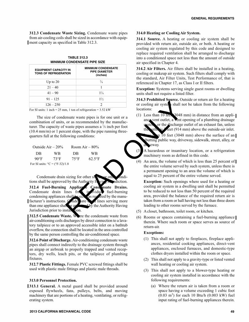
312.3 Condensate Waste Sizing. Condensate waste pipesfrom air-cooling coils shall be sized in accordance with equip-ment capacity as specified in Table 312.3.
The size of condensate waste pipes is for one unit or acombination of units, or as recommended by the manufac-turer. The capacity of waste pipes assumes a 1⁄8 inch per foot(10.4 mm/m) or 1 percent slope, with the pipe running three-quarters full at the following conditions:
Condensate drain sizing for other slopes or other condi-tions shall be approved by the Authority Having Jurisdiction.312.4 Fuel-Burning Appliance Condensate Drains.Condensate drain lines from individual fuel-burningcondensing appliances shall be sized as required by the manu-facturer’s instructions. Condensate drain lines serving morethan one appliance shall be approved by the Authority HavingJurisdiction prior to installation.312.5 Condensate Waste.Where the condensate waste fromair-conditioning coils discharges by direct connection to a lava-tory tailpiece or to an approved accessible inlet on a bathtuboverflow, the connection shall be located in the area controlledby the same person controlling the air-conditioned space.312.6 Point of Discharge.Air-conditioning condensate wastepipes shall connect indirectly to the drainage system throughan airgap or airbreak to properly trapped and vented recep-tors, dry wells, leach pits, or the tailpiece of plumbingfixtures.312.7 Plastic Fittings. Female PVC screwed fittings shall beused with plastic male fittings and plastic male threads.
313.0 Personnel Protection.313.1 General. A metal guard shall be provided aroundexposed flywheels, fans, pulleys, belts, and movingmachinery that are portions of a heating, ventilating, or refrig-erating system.
314.0 Heating or Cooling Air System.314.1 Source. A heating or cooling air system shall beprovided with return air, outside air, or both. A heating orcooling air system regulated by this code and designed toreplace required ventilation shall be arranged to dischargeinto a conditioned space not less than the amount of outsideair specified in Chapter 4.314.2 Air Filters. Air filters shall be installed in a heating,cooling or makeup air system. Such filters shall comply withthe standard, Air Filter Units, Test Performance of, that isreferenced in Chapter 17, as Class I or II filters.Exception: Systems serving single guest rooms or dwellingunits shall not require a listed filter.314.3 Prohibited Source. Outside or return air for a heatingor cooling air system shall not be taken from the followinglocations:(1) Less than 10 feet (3048 mm) in distance from an appli-
ance vent outlet, a vent opening of a plumbing drainagesystem, or the discharge outlet of an exhaust fan, unlessthe outlet is 3 feet (914 mm) above the outside-air inlet.
(2) Less than 10 feet (3048 mm) above the surface of anabutting public way, driveway, sidewalk, street, alley, ordriveway.
(3) A hazardous or insanitary location, or a refrigerationmachinery room as defined in this code.
(4) An area, the volume of which is less than 25 percent ofthe entire volume served by such system, unless there isa permanent opening to an area the volume of which isequal to 25 percent of the entire volume served.Exception: Such openings where used for a heating orcooling air system in a dwelling unit shall be permittedto be reduced to not less than 50 percent of the requiredarea, provided the balance of the required return air istaken from a room or hall having not less than three doorsleading to other rooms served by the furnace.
(5) A closet, bathroom, toilet room, or kitchen.(6) Rooms or spaces containing a fuel-burning appliance
therein. Where such room or space serves as source ofreturn-air.Exceptions:(1) This shall not apply to fireplaces, fireplace appli-
ances, residential cooking appliances, direct-ventappliances, enclosed furnaces, and domestic-typeclothes dryers installed within the room or space.
(2) This shall not apply to a gravity-type or listed ventedwall heating or cooling air system.
(3) This shall not apply to a blower-type heating orcooling air system installed in accordance with thefollowing requirements:(a) Where the return air is taken from a room or
space having a volume exceeding 1 cubic foot(0.03 m3) for each 10 Btu/h (0.003 kW) fuelinput rating of fuel-burning appliances therein.
Outside Air – 20% Room Air – 80%DB WB DB WB90°F 73°F 75°F 62.5°F
For SI units: °C = (°F-32)/1.8
For SI units: 1 inch = 25 mm, 1 ton of refrigeration = 3.52 kW
EQUIPMENT CAPACITY IN TONS OF REFRIGERATION
MINIMUM CONDENSATEPIPE DIAMETER
(inches)
Up to 20 3⁄421 – 40 141 – 90 11⁄491 – 125 11⁄2126 – 250 2
TABLE 312.3MINIMUM CONDENSATE PIPE SIZE
49
GENERAL REQUIREMENTS
2013 CALIFORNIA MECHANICAL CODE
READ ONLY

(b) Not less than 75 percent of the supply air isdischarged back into the same room or space.
(c) Return-air inlets shall not be located within 10feet (3048 mm) from an appliance firebox ordraft diverter in the same enclosed room orconfined space.
314.4 Return-Air Limitations. Return air from one dwellingunit shall not discharge into another dwelling unit through theheating or cooling air system.
315.0 Water Supply.315.1 General. Water supply and backflow protection shallbe in accordance with the California Plumbing Code.
316.0 Pipe, Tube Hangers, and Supports.316.1 General. Piping and tubing shall be supported in accor-dance with this section, the manufacturer’s instructions, andin accordance with the Authority Having Jurisdiction.316.2 Suspended Piping. Suspended piping shall besupported at intervals not to exceed those shown in Table316.2.316.3 Piping Support. Piping shall be supported in such amanner as to maintain its alignment and prevent sagging.316.4 Strength. Hangers and anchors shall be of sufficientstrength to support the weight of the pipe and its contents.Piping shall be isolated from incompatible materials.316.5 Hanger Rod Sizes. Hanger rod sizes shall be notsmaller than those shown in Table 316.5.
316.6 Gas Piping. Gas piping shall be supported by metalstraps or hooks at intervals not to exceed those shown in Table1311.2.5.1.316.7 In Ground. Piping and tubing in the ground shall belaid on a firm bed for its entire length except where otherwiseapproved by the Authority Having Jurisdiction. Asbestos-cement piping shall be provided with approved thrustblocking.
317.0 Balancing.317.1 General. Heating, ventilating, and air-conditioningsystems (including hydronic systems) shall be balanced inaccordance with one of the following methods:(1) AABC National Standards for Total System Balance(2) ACCA Manual B
(3) ASHRAE 111(4) NEBB Procedural Standards for Testing Adjusting
Balancing of Environmental Systems(5) SMACNA HVAC Systems Testing, Adjusting, and
Balancing
318.0 Louvers in Hurricane Prone Regions.318.1 General. Louvers located in areas within hurricane-prone regions that are within 1 mile (2 km) of the coastal meanhigh water line where the basic wind speed is 110 miles perhour (mi/h) (49.2 m/s) or greater; or portions of hurricane-prone regions where the basic wind speed is 120 mi/h (53.6m/s) or greater; or Hawaii, as described in ASCE 7 shall betested in accordance with Section 318.1.1 and Section 318.1.2.
318.1.1 Testing. Louvers that protect air intake orexhaust openings shall be tested in accordance withAMCA 550 for resistance to wind-driven rain.318.1.2 Impact Resistance Test. Upon request by theAuthority Having Jurisdiction, louvers protecting intakeand exhaust ventilation ducts that are not fixed in theopen position and located within 30 feet (9144 mm) ofthe grade shall be tested for impact resistance in accor-dance with AMCA 540.
319.0 Protection of Piping, Materials, and Structures.319.1 General. Piping passing under or through walls shallbe protected from breakage. Piping passing through or undercinders or other corrosive materials shall be protected fromexternal corrosion in an approved manner. Approved provi-sions shall be made for expansion of hot water piping. Voidsaround piping passing through concrete floors on the groundshall be sealed.
320.0 Sleeves for Piping.320.1 General. Sleeves shall be provided to protect pipingthrough concrete and masonry walls and concrete floors.Exception: Sleeves shall not be required where openings aredrilled or bored.320.2 Bearing. Piping through concrete or masonry wallsshall not be subject to a load from building construction.320.3 Sealing. In exterior walls, annular space between sleevesand pipes shall be sealed and made watertight, as approved bythe Authority Having Jurisdiction. A penetration through fire-resistive construction shall be in accordance with the buildingcode and applicable standards referenced in Table 1701.0.320.4 Through Firewall. A pipe sleeve through a firewallshall have the space around the pipe completely sealed withan approved fire-resistive material in accordance with othercodes.
321.0 Cutting Structure.321.1 General. A structural member weakened or impairedby cutting, notching, or otherwise shall be reinforced,
PIPE AND TUBE SIZE(inches)
ROD SIZES(inches)
1⁄2 - 4 3⁄85 - 8 1⁄2
10 - 12 5⁄8
TABLE 316.5HANGER ROD SIZES
For SI units: 1 inch = 25.4 mm
50
GENERAL REQUIREMENTS
2013 CALIFORNIA MECHANICAL CODE
READ ONLY

51
GENERAL REQUIREMENTS
2013 CALIFORNIA MECHANICAL CODE
repaired, or replaced so as to be left in a safe structural condi-tion in accordance with the requirements of the building code.
322.0 Ratproofing.322.1 General. Mechanical system shall be constructed insuch a manner that rats cannot enter a building by followingthe duct work from the outside into the building.322.2 Ductwork or Pipes. In or on buildings where openingshave been made in walls, floors, or ceilings for the passage ofductwork or pipes, such openings shall be closed andprotected by the installation of approved metal collarssecurely fastened to the adjoining structure.
323.0 Scope.323.1 Applicability. This part is applicable to health facili-ties regulated by OSHPD (See Adoption Tables for applica-tion for specific sections).Note: This section has no corresponding provisions in theUMC. For the scope and authority of each state agency, referto Chapter 1.323.2 Services/Systems and Utilities. Refer to Section1224.4.1 of the California Building Code.
324.0 Steam and Hot-Water Systems.324.1 Requirements for Hospitals and Optional ServicesProvided in Correctional Treatment Centers. [OSHPD 1 & 4]
324.1.1 Boilers shall have the capacity, based upon therest ratings published by the Hydronics Institute oranother acceptable national standard to supply thenormal operating requirements of all connected systemsand equipment.324.1.2 A minimum of two boilers shall be provided. Thearrangement of boilers shall be based on the capacityand capability of a boiler or boilers to operate allsystems during-periods of breakdown or maintenance ofany one boiler.324.1.3 Boiler systems providing space heating shall bedesigned to maintain a minimum temperature of 60°F(15.6°C) in general patient areas and the temperaturesspecified in Table 325.0 for sensitive areas duringperiods of breakdown or maintenance of any one boiler.Winter design temperature shall be based on the Medianof Extremes shown by the 1982 ASHRAE Climatic Datafor Region X and ASHRAE 1994 Supplement to ClimaticData for Region X.324.1.4 Boiler feed pumps, condensate return pumps,fuel oil pumps, and heating circulating pumps shall beconnected and installed to provide standby service in theevent of pump failure. Installation of duplex pumps orprovision of a spare pump will meet this requirement.324.1.5 At least two sources of heat (e.g. two pieces ofequipment) shall be provided for supplying essentialservices such as sterilizers, hot water for dishwashing,and domestic hot water for minimum patient service,
such as handwashing and baths. Booster heaters fordishwashing providing 125°F to 180°F (52°C to 82°C)water may be counted as the second source of heat forthat service.
324.2 Requirements for Skilled Nursing, Intermediate CareFacilities and Basic Services Provided in CorrectionalTreatment Centers. [For OSHPD 2 & 4]
324.2.1 Boilers, if provided, shall accommodate Section324.1.324.2.2 Two or more interconnected water heaters arean acceptable means to provide two sources of heat forhot water (See Section 324.1.5).
325.0 Air Conditioning and Heating Systems.325.1 Requirements for Hospitals and Optional ServicesProvided in Correctional Treatment Centers. [OSHPD 1 & 4]
325.1.1 The systems shall be designed to provide thetemperatures and relative humidity for sensitive areas orrooms shown in Table 325.0. When outdoor humidity andinternal moisture sources are not sufficient to meet therequirements of Table 325.0, humidification shall beprovided by means of the health-care facility air-handling systems. Temperature shall be individuallycontrolled for each operating and delivery room. Burnunit patient rooms that require humidifiers to complywith Table 325.0 shall be provided with individualhumidity control.325.1.2 For occupied areas not shown in Table 325.0,heating systems shall be designed to provide 70°F to75°F (21.1°C to 23.9°C) based on the Median ofExtremes shown by the 1982 ASHRAE Climatic Data forRegion X and ASHRAE 1994 Supplement to ClimaticData for Region X. The systems shall be thermostaticallycontrolled with appropriate zoning to achieve the aboveconditions.325.1.3 For occupied areas not shown in Table 325.0,cooling systems shall be designed to provide 75°F(23.9°C) maximum based on the 0.5 percent summerdesign dry bulb temperatures shown by the 1982ASHRAE Climatic Data for Region X and ASHRAE 1994Supplement to Climatic Data for Region X. The systemsshall be thermostatically controlled with appropriatezoning to achieve the above conditions.
325.2 Requirements for Skilled Nursing, Intermediate CareFacilities and Basic Services Provided in CorrectionalTreatment Centers. [For OSHPD 2 & 4]
325.2.1 Systems shall accommodate the provisions ofSection 325.1.2 through 325.1.3.325.2.2 Where air conditioning is provided, the systemshall be thermostatically controlled in one or more zones.
325.3 Requirements for Outpatient Facilities and LicensedClinics. [For OSHPD 3]
325.3.1 The system shall be designed to provide thetemperature and humidities for sensitive areas for roomsshown in Table 325.0.
READ ONLY

52
GENERAL REQUIREMENTS
2013 CALIFORNIA MECHANICAL CODE
TABLE 325.0HEATING, COOLING, AND RELATIVE HUMIDITY
REQUIREMENTS FOR SENSITIVE AREAS OR ROOMS
1 Thermostats and humidistat shall be either locally resetable and of thenon-locking type or remotely resetable and of the locking type.
2 Systems shall be capable of maintaining the rooms within the rangeduring normal operation. Lower or higher temperature shall be permittedwhen patients’ comfort and/or medical conditions require those condi-tions.
3 The ranges listed are the minimum and maximum limits where control isspecifically needed.
4 Types of intensive care service spaces are listed in the CaliforniaBuilding Code.
326.0 Essential Mechanical Provisions. [OSHPD 1, 2, 3(Surgical Clinics only) & 4] During periods of poweroutages essential electrical power shall be provided for thefollowing equipment:326.1 (Does not apply to OSHPD 3 surgical clinic.) Allheating equipment necessary to maintain a minimum temper-ature of 60°F (15.6°) in patient areas which are not specifiedin Table 325.0.326.2 All heating equipment necessary to maintain theminimum temperatures for sensitive areas as specified inTable 325.0.326.3 Equipment necessary for humidification of the areaslisted in Table 325.0.326.4 All supply, return, and exhaust fans required to main-tain the positive and negative air balances as required inTable 4-A.326.5 All control components and control systems necessaryfor the normal operation of equipment required to have essen-tial electrical power.326.6 Alarms for airborne infection isolation rooms andprotective environment rooms.
Area or Rooms Designation
TEMPERATURERANGE1, 2
RELATIVEHUMIDITY1, 3
°F PercentOperating room 68-75 20-60Cystoscopy 68-75 20-60Cardiac catheterization lab 70-75 max 60Trauma/cardiac room 70-75 20-60Delivery room, Caesarean operating room 68-75 20-60
Gastrointestinal endoscopyprocedure room 68-73 20-60
Post-Anesthesia Care Unit 70-75 30-60Newborn nursery 72-78 30-60Newborn Intensive-care nursery unit 70-75 30-60Intensive care4 70-75 30-60Burn Unit 70-75 40-60
READ ONLY

53
GENERAL REQUIREMENTS
2013 CALIFORNIA MECHANICAL CODE
TABLE 303.3(1)CLEARANCES, IN INCHES, WITH SPECIFIED FORMS OF PROTECTION1, 2
TYPE OF PROTECTION4Applied to the Combustible Mate-rial Unless Otherwise Specified andCovering All Surfaces within theDistance Specified as the RequiredClearance with No Protection(Thicknesses Are Minimum)
WHERE THE STANDARD CLEARANCE IN TABLE 303.4 WITH NO PROTECTION IS:36 (inches) 18 (inches) 12 (inches) 9 (inches) 6 (inches)
ABOVESIDESANDREAR
CHIMNEY ORVENT
CONNECTORABOVE
SIDESANDREAR
CHIMNEY ORVENT
CONNECTORABOVE
SIDESANDREAR
CHIMNEY ORVENT
CONNECTORABOVE
SIDESANDREAR
CHIMNEY ORVENT
CONNECTOR
(a) 1⁄4 of an inch insulating mill-board spaced out 1 inch3 30 18 30 15 9 12 9 6 6 3 2 3
(b) 0.013 inch (No. 28 manu-facturer’s standard gauge)steel sheet on 1⁄4 of an inchinsulating millboard
24 18 24 12 9 12 9 6 4 3 2 2
(c) 0.013 inch (No. 28 manu-facturer’s standard gauge)steel sheet spaced out 1inch3
18 12 18 9 6 9 6 4 4 2 2 2
(d) 0.013 inch (No. 28 manu-facturer’s standard gauge)steel sheet on 1⁄8 of an inchinsulating millboard spacedout 1 inch3
18 12 18 9 6 9 6 4 4 2 2 2
(e) 11⁄2 inch insulating cementcovering on heating appli-ance
18 12 36 9 6 18 6 4 9 2 1 6
(f) 1⁄4 of an inch insulating mill-board on 1 inch mineralfiber batts reinforced withwire mesh or equivalent
18 12 18 6 6 6 4 4 4 2 2 2
(g) 0.027 inch (No. 22 manu-facturer’s standard gauge)steel sheet on 1 inch mineralfiber batts reinforced withwire or equivalent
18 12 12 4 3 3 2 2 2 2 2 2
(h) 1⁄4 of an inch insulating mill-board 36 36 36 18 18 18 12 12 9 4 4 4
For SI units: 1 inch = 25.4 mmNotes:1 For appliances complying with Section 303.3 and Section 303.4.2 Except for the protection described in (e), clearances shall be measured from the outer surface of the appliance to the combustible material, disregarding an
intervening protection applied to the combustible material.3 Spacers shall be of noncombustible material.4 Insulating millboard is a factory-made product formed of noncombustible materials, normally fibers, and having a thermal conductivity of 1 British thermal
unit inch per hour square foot degree Fahrenheit [Btu•in/(h•ft2•°F)] [0.1 W/(m•K)] or less.
Notes:1. Dimension shall be not less than the required clearance with no protection set forth in Table 303.4 and Table 303.3(2) and in section applying to various
types of appliances. 2. Dimension shall be not less than the reduced clearance set forth in Table 303.3(1).3. Dimension shall be not less than the clearance required for dimension A.
FIGURE 303.3EXTENT OF PROTECTION REQUIRED TO REDUCE CLEARANCES FROM APPLIANCE, CHIMNEY, OR VENT CONNECTORS
[NFPA 211: FIGURE 9.5.1.1]
READ ONLY

54
GENERAL REQUIREMENTS
2013 CALIFORNIA MECHANICAL CODE
DESCRIPTION OF APPLIANCES MINIMUM CLEARANCE1(inches)
RESIDENTIAL-TYPE APPLIANCES ––SINGLE-WALL METAL PIPE CONNECTORS2 ––
Gas appliances without draft hoods 18Electric, gas, and oil incinerators 18Oil and solid-fuel appliances 18Unlisted gas appliances with draft hoods 9Boilers and furnaces equipped with listed gas burners and with draft hoods3 9Oil appliances listed as approved for use with Type L venting systems (but only where connected tochimneys) 9
Listed gas appliances with draft hoods 6TYPE L VENTING SYSTEM PIPING CONNECTORS
Gas appliances without draft hoods 9Electric, gas, and oil incinerators 9Oil and solid-fuel appliances 9Unlisted gas appliances with draft hoods 6Boilers and furnaces equipped with listed gas burners and with draft hoods 6Oil appliances listed as suitable for use with Type L venting systems4 ––
Listed gas appliances with draft hoods5 ––TYPE B GAS VENT PIPING CONNECTORS ––
Listed gas appliances with draft hoods5 ––COMMERCIAL-INDUSTRIAL TYPE APPLIANCES ––LOW-HEAT APPLIANCES ––
SINGLE-WALL METAL PIPE CONNECTORS2 ––Gas, oil, and solid-fuel boilers, furnaces, and water heaters 18Ranges, restaurant-type 18Oil unit heaters 18Unlisted gas unit heaters 18Listed gas unit heaters with draft hoods 6Other low-heat industrial appliances 18
MEDIUM-HEAT APPLIANCES ––SINGLE-WALL METAL PIPE CONNECTORS2 ––All gas, oil, and solid-fuel appliances 36
TABLE 303.3(2)CHIMNEY CONNECTOR AND VENT CONNECTOR CLEARANCES
FROM COMBUSTIBLE MATERIALS[NFPA 211: TABLE 9.5.1.1]
For SI units: 1 inch = 25.4 mmNotes:1 These clearances apply except where the listing of an appliance specifies different clearance, in which case the listed clearance takes precedence.2 The clearances from connectors to combustible materials shall be permitted to be reduced where the combustible material is protected in accordance with
Table 303.3(1).3 The dimension shall be permitted to be 6 inches (152 mm), provided the maximum flue temperatures entering the draft hood do not exceed 550°F (288°C).4 Where listed Type L venting system piping is used, the clearance shall be permitted to be in accordance with the venting system listing.5 Where listed Type B or Type L venting system piping is used, the clearance shall be permitted to be in accordance with the venting system listing.
READ ONLY
55
GENERAL REQUIREMENTS
2013 CALIFORNIA MECHANICAL CODE
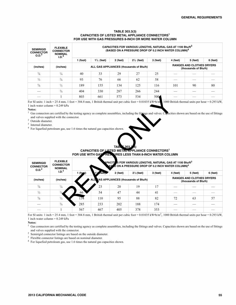
SEMIRIGID CONNECTOR
O.D.2
FLEXIBLE CONNECTOR NOMINALI.D.3
CAPACITIES FOR VARIOUS LENGTHS, NATURAL GAS AT 1100 Btu/ft3(BASED ON A PRESSURE DROP OF 0.2 INCH WATER COLUMN)4
1 (foot) 11⁄2 (feet) 2 (feet) 21⁄2 (feet) 3 (feet) 4 (feet) 5 (feet) 6 (feet)
(inches) (inches) ALL GAS APPLIANCES (thousands of Btu/h) RANGES AND CLOTHES DRYERS(thousands of Btu/h)
3⁄8 1⁄4 40 33 29 27 25 — — —1⁄2 3⁄8 93 76 66 62 58 — — —5⁄8 1⁄2 189 155 134 125 116 101 90 80
— 3⁄4 404 330 287 266 244 — — —— 1 803 661 573 534 500 — — —
SEMIRIGID CONNECTOR
O.D.2
FLEXIBLE CONNECTOR NOMINALI.D.3
CAPACITIES FOR VARIOUS LENGTHS, NATURAL GAS AT 1100 Btu/ft3(BASED ON A PRESSURE DROP OF 0.2 INCH WATER COLUMN)4
1 (foot) 11⁄2 (feet) 2 (feet) 21⁄2 (feet) 3 (feet) 4 (feet) 5 (feet) 6 (feet)
(inches) (inches) ALL GAS APPLIANCES (thousands of Btu/h) RANGES AND CLOTHES DRYERS(thousands of Btu/h)
3⁄8 1⁄4 28 23 20 19 17 — — —1⁄2 3⁄8 66 54 47 44 41 — — —5⁄8 1⁄2 134 110 95 88 82 72 63 57
— 3⁄4 285 233 202 188 174 — — —— 1 567 467 405 378 353 — — —
For SI units: 1 inch = 25.4 mm, 1 foot = 304.8 mm, 1 British thermal unit per cubic foot = 0.01035 kW•h/m3, 1000 British thermal units per hour = 0.293 kW,1 inch water column = 0.249 kPaNotes:1 Gas connectors are certified by the testing agency as complete assemblies, including the fittings and valves. Capacities shown are based on the use of fittings
and valves supplied with the connector.2 Outside diameter.3 Internal diameter.4 For liquefied petroleum gas, use 1.6 times the natural gas capacities shown.
For SI units: 1 inch = 25.4 mm, 1 foot = 304.8 mm, 1 British thermal unit per cubic foot = 0.01035 kW•h/m3, 1000 British thermal units per hour = 0.293 kW,1 inch water column = 0.249 kPaNotes:1 Gas connectors are certified by the testing agency as complete assemblies, including the fittings and valves. Capacities shown are based on the use of fittings
and valves supplied with the connector.2 Semirigid connector listings are based on the outside diameter.3 Flexible connector listings are based on nominal diameter.4 For liquefied petroleum gas, use 1.6 times the natural gas capacities shown.
TABLE 303.3(3)CAPACITIES OF LISTED METAL APPLIANCE CONNECTORS1
FOR USE WITH GAS PRESSURES 8-INCH OR MORE WATER COLUMN
TABLE 303.3(4)CAPACITIES OF LISTED METAL APPLIANCE CONNECTORS1
FOR USE WITH GAS PRESSURES LESS THAN 8-INCH WATER COLUMN
READ ONLY

56
GENERAL REQUIREMENTS
2013 CALIFORNIA MECHANICAL CODE
TABLE 303.4STANDARD INSTALLATION CLEARANCES IN INCHES FOR UNLISTED HEAT-PRODUCING APPLIANCES
RESIDENTIAL-TYPE APPLIANCES FUEL
APPLIANCE
ABOVE TOP OFCASING ORAPPLIANCE
FROM TOP ANDSIDES OF WARM-AIR BONNET OR
PLENUM
FROMFRONT1
FROMBACK
FROMSIDES
BOILERS AND WATER HEATERS11
Steam Boilers – 15 pounds-force per square inch (psi) Water Boilers – 250°F Water Heaters – 200°F All Water Walled or Jacketed
Automatic Oil or Comb. Gas-OilAutomatic Gas
Solid
666
–––
241848
666
666
FURNACES – CENTRAL;OR HEATERS11 –ELECTRIC CENTRAL WARM AIR FURNACES
Gravity, Upflow, Downflow, Horizontal and DuctWarm Air – 250°F max.
Automatic Oil orComb. Gas-OilAutomatic Gas
SolidElectric
62
62
183
62
2462
183
62
6184818
66186
66186
FURNACES – FLOORFor Mounting in Combustible Floors
Automatic Oil orComb. Gas-OilAutomatic Gas
3636
––
1212
1212
1212
HEAT EXCHANGERSSteam – 15 psi max.Hot Water – 250°F max.
– 1 1 1 1 1
ROOM HEATERS4
Circulating TypeRadiant or Other Type
Oil or SolidGas
Oil or SolidGas
Gas with doublemetal or ceramic
back
36363636
36
––––
–
24243636
36
12123618
12
12123618
18
Fireplace Stove Solid 485 – 54 485 485
RADIATORSSteam or Hot Water6 – 36 – 6 6 6
RANGES – COOKING STOVES – FiringSide
Opp.Side
OilGas
Solid Clay-LinedFirepot
Solid UnlinedFirepot
Electric
307
307
307
307
307
–
–
–
–
–
––
–
––
96
24
366
246
24
36
186
18
186
INCINERATORSDomestic Types – 368 – 48 36 36
COMMERCIAL INDUSTRIAL-TYPE APPLIANCES ANY AND ALL PHYSICAL SIZES EXCEPT AS NOTED11 FUEL
APPLIANCE
ABOVE TOP OFCASING ORAPPLIANCE
FROM TOP ANDSIDES OF WARM-AIR BONNET OR
PLENUM
FROMFRONT1
FROMBACK9
FROMSIDES9
BOILERS AND WATER HEATERS11
100 cubic feet or lessSteam, any pressure
50 psi or lessAny size
All Fuels
All Fuels
18
18
––
48
48
18
18
18
18
UNIT HEATERSFloor Mounted or Suspended – Any SizeSuspended – 100 cubic feet or less
Suspended – 100 cubic feet or lessSuspended – Over 100 cubic feet
Steam or HotWater
Oil or Comb.Gas-Oil
GasAll FuelsAll Fuels
1
661818
–––––
–
24184848
1
18181818
1
18181818
RANGES – RESTAURANT – TYPEFloor Mounted All Fuels 48 – 48 18 18
OTHER LOW-HEAT INDUSTRIAL APPLIANCESFloor Mounted or Suspended – 18 18 48 18 18
READ ONLY
57
GENERAL REQUIREMENTS
2013 CALIFORNIA MECHANICAL CODE
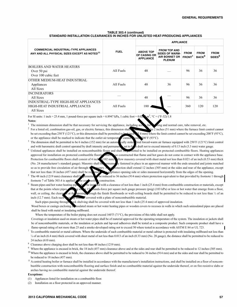
COMMERCIAL INDUSTRIAL-TYPE APPLIANCES ANY AND ALL PHYSICAL SIZES EXCEPT AS NOTED11 FUEL
APPLIANCE
ABOVE TOPOF CASING ORAPPLIANCE
FROM TOP ANDSIDES OF WARM-AIR BONNET OR
PLENUM
FROMFRONT1
FROMBACK9
FROMSIDES9
BOILERS AND WATER HEATERSOver 50 psi Over 100 cubic feet
All Fuels 48 –– 96 36 36
OTHER MEDIUM-HEAT INDUSTRIALAppliancesAll Sizes
All Fuels 48 36 96 36 36
INCINERATORSAll Sizes –– 48 –– 96 36 36
INDUSTRIAL-TYPE HIGH-HEAT APPLIANCESHIGH-HEAT INDUSTRIAL APPLIANCES
All SizesAll Fuels 180 –– 360 120 120
For SI units: 1 inch = 25.4 mm, 1 pound-force per square inch = 6.8947 kPa, 1 cubic foot = 0.0283 m3, °C = (°F-32)/1.8Notes:1 The minimum dimension shall be that necessary for servicing the appliance, including access for cleaning and normal care, tube removal, etc.2 For a listed oil, combination gas-oil, gas, or electric furnace, this dimension shall be permitted to be 2 inches (51 mm) where the furnace limit control cannot
be set exceeding than 250˚F (121°C), or this dimension shall be permitted to be 1 inch (25.4 mm) where the limit control cannot be set exceeding 200˚F (93°C),or the appliance shall be marked to indicate that the outlet air temperature cannot exceed 200˚F (93°C).
3 The dimension shall be permitted to be 6 inches (152 mm) for an automatically stoker-fired forced-warm air furnace equipped with 250˚F (121°C) limit controland with barometric draft control operated by draft intensity and permanently set to limit draft not to exceed intensity of 0.13 inch (3.3 mm) water gauge.
4 Unlisted appliances shall be installed on noncombustible floors and shall be permitted to be installed on protected combustible floors. Heating appliancesapproved for installation on protected combustible flooring shall be so constructed that flame and hot gases do not come in contact with the appliance base.Protection for combustible floors shall consist of 4 inches (102 mm) hollow masonry covered with sheet metal not less than 0.021 of an inch (0.53 mm) thick(No. 24 manufacturer’s standard gauge). Masonry shall be permanently fastened in place in an approved manner with the ends unsealed and joints matchedso as to provide free circulation of air through the masonry. Floor protection shall extend 12 inches (305 mm) at the sides and rear of the appliance, exceptthat not less than 18 inches (457 mm) shall be required on the appliance opening side or sides measured horizontally from the edges of the opening.
5 The 48 inch (1219 mm) clearance shall be permitted to be reduced to 36 inches (914 mm) where protection equivalent to that provided by footnote 1 throughfootnote 7 of Table 303.4 is applied to the combustible construction.
6 Steam pipes and hot water heating pipes shall be installed with a clearance of not less than 1 inch (25.4 mm) from combustible construction or materials, exceptthat at the points where pipes carrying steam 15 pounds-force per square inch gauge pressure (psig) (103 kPa) or less or hot water that emerge from a floor,wall, or ceiling, the clearance at the opening through the finish floorboards or wall-ceiling boards shall be permitted to be reduced to not less than 1⁄2 of aninch (12.7 mm). Each such opening shall be covered with a plate of noncombustible material.
Such pipes passing through stock shelving shall be covered with not less than 1 inch (25.4 mm) of approved insulation.Wood boxes or casings enclosing uninsulated steam or hot water heating pipes or wooden covers to recesses in walls in which such uninsulated pipes are placedshall be lined with metal or insulating millboard.
Where the temperature of the boiler piping does not exceed 160˚F (71°C), the provisions of this table shall not apply.Coverings or insulation used on steam or hot water pipes shall be of material approved for the operating temperature of the system. The insulation or jackets shallbe of noncombustible materials, or the insulation or jackets and lap-seal adhesives shall be tested as a composite product. Such composite product shall have aflame-spread rating of not more than 25 and a smoke-developed rating not to exceed 50 where tested in accordance with ASTM E 84 or UL 723.
7 To combustible material or metal cabinets. Where the underside of such combustible material or metal cabinet is protected with insulating millboard not less than1⁄4 of an inch (6.4 mm) thick covered with sheet metal of not less than 0.013 of an inch (0.33 mm) (No. 28 gauge), the distance shall be permitted to be reduced to24 inches (610 mm).
8 Clearance above charging door shall be not less than 48 inches (1219 mm).9 Where the appliance is encased in brick, the 18 inch (457 mm) clearance above and at the sides and rear shall be permitted to be reduced to 12 inches (305 mm).10Where the appliance is encased in brick, the clearance above shall be permitted to be reduced to 36 inches (914 mm) and at the sides and rear shall be permitted to
be reduced to 18 inches (457 mm).11 A central heating boiler or furnace shall be installed in accordance with the manufacturer's installation instructions, and shall be installed on a floor of noncom-
bustible construction with noncombustible flooring and surface finish and no combustible material against the underside thereof, or on fire-resistive slabs orarches having no combustible material against the underside thereof.
Exceptions:(1) Appliances listed for installation on a combustible floor.(2) Installation on a floor protected in an approved manner.
TABLE 303.4 (continued)STANDARD INSTALLATION CLEARANCES IN INCHES FOR UNLISTED HEAT-PRODUCING APPLIANCES
READ ONLY

58
GENERAL REQUIREMENTS
2013 CALIFORNIA MECHANICAL CODE
MATERIALS TYPES OF JOINTS HORIZONTAL VERTICAL
CastLead and Oakum 5 feet, except 10 feet where 10 foot
lengths are installed1, 2, 3 Base and each floor, not to exceed 15 feet
Compression Gasket Every other joint, unless over 4 feetthen support each joint1, 2, 3 Base and each floor, not to exceed 15 feet
Cast-Iron Hubless Shielded Coupling Every other joint, unless over 4 feetthen support each joint1, 2, 3, 4 Base and each floor, not to exceed 15 feet
Copper Tube and Pipe Soldered or Brazed 11⁄2 inches and smaller, 6 feet; 2 inchesand larger, 10 feet Each floor, not to exceed 10 feet5
Steel and Brass Pipe forWater DWV Threaded or Welded
3⁄4 inch and smaller, 10 feet; 1 inch andlarger, 12 feet Every other floor, not to exceed 25 feet5
Steel, Brass, and TinnedCopper Pipe for Gas Threaded or Welded
1⁄2 inch, 6 feet; 3⁄4 inch and 1 inch 8feet; 11⁄4 and larger, 10 feet
1⁄2 inch, 6 feet; 3⁄4 and 1 inch, 8 feet;11⁄4 every floor level
Schedule 40 PVC andABS Solvent Cemented All sizes, 4 feet; allow for expansion
every 30 feet3Base and each floor; provide mid-story
guides; provide for expansion every 30 feet
CPVC Solvent Cemented 1 inch and smaller, 3 feet; 11⁄4 inch andlarger, 4 feet Base and each floor; provide mid-story guides
Lead Wiped or Burned Continuous Support Not to exceed 4 feetCopper Mechanical In accordance with standards acceptable to the Authority Having Jurisdiction
Steel and Brass Mechanical In accordance with standards acceptable to the Authority Having Jurisdiction
PEX Metal insert and metalcompression 32 inches Base and each floor;
provide mid-story guides
PEX-AL-PEX Metal insert and metalcompression
1⁄2 inch3⁄4 inch1 inch
} All sizes 98 inches Base and each floor;provide mid-story guides
PE-AL-PE Metal insert and metalcompression
1⁄2 inch3⁄4 inch1 inch
} All sizes 98 inches Base and each floor; provide mid-story guides
Polypropylene
Fusion weld (socket, butt,saddle, electrofusion),threaded (metal threadsonly), or mechanical
1 inch and smaller, 32 inches;11⁄4 inches and larger, 4 feet
Base and each floor; provide mid-story guides
TABLE 316.2HANGER AND SUPPORTS
For SI unit: 1 inch = 25.4 mm, 1 foot = 304.8 mmNotes:1 Support adjacent to joint, not to exceed 18 inches (457 mm).2 Brace not to exceed 40 feet (12 192 mm) intervals to prevent horizontal movement.3 Support at each horizontal branch connection.4 Hangers shall not be placed on the coupling.5 Vertical water lines shall be permitted to be supported in accordance with recognized engineering principles with regard to expansion and contraction, where
first approved by the Authority Having Jurisdiction.
READ ONLY