read this manual thoroughly - crusader …€¦ · the years, pleasurecraft engine group, through...
TRANSCRIPT
Welcome to the growing family of Crusader Marine Engines owners. We are delighted you have chosen Crusader power for your boat and wish you many years of enjoyment.
When you chose Crusader, you selected the utmost in premium power for your boating application. Crusader is the world’s largest manufacturer of gasoline marine inboards, and the clear-cut leader in cutting edge technology. Over the years, Pleasurecraft Engine Group, through Crusader and PCM, has introduced many breakthrough innovations that quickly became industry standards. The pyramidal exhaust system, light-weight transmissions, computerized engine control, micro adjustable all stainless steel mounts, and the Fuel Control Cell (FCC) are all Pleasurecraft innovations. No matter which Crusader model you purchased, you can be sure it is equipped with the latest in modern technology for added performance and durability.
READ THIS MANUAL THOROUGHLY
Before starting your engine(s), READ THIS MANUAL CAREFULLY AND COMPLETELY. If you do not understand any portion of the manual, contact your Dealer for clarification or assistance. Ask your Dealer for a demonstration of actual starting and operating procedures.
The descriptions and specifications contained in this manual were in effect at the time of printing. Crusader Marine Engines’ policy of continued improvement reserves the right to change specifications or design without notice and without obligation.
This manual will cover the following year of manufacture Crusader engines:
Year Model 2013 5.7L Carburetor
Part Number - L510019-13 Printed 12/12

This Page Was
Intentionally
Left Blank

1L510019-13
1 - SERVICE AND WARRANTY ............................................................................................... 4-16Safety Information ...................................................................................................................... 4Replacement Parts ........................................................................................................................... 4Safety Warnings ......................................................................................................................... 4Crusader Marine Engines’ Commitment to You ................................................................................. 5Owner Warranty Registration (Warranty Registration Card is located at the back of this manual) ................ 5Engine Operation and Care .......................................................................................................... 6Maintenance Records ................................................................................................................. 6Local Repair Service ................................................................................................................... 6Service Away From Home ............................................................................................................ 6Replacement Parts Inquiries ......................................................................................................... 7Replacement Service Parts .......................................................................................................... 7Applicable Limited Warranty ......................................................................................................... 7Crusader Marine Engines Two-Year Limited Warranty(For Engines Sold and Used in the United States and Canada) ........................................................... 8Items Not Covered Under the Limited Warranty ............................................................................... 10Things You Should Know About The Warranty ................................................................................ 11Marine Transmissions ................................................................................................................ 12Resolving a Service Problem .......................................................................................................13Crusader Master Distributors .......................................................................................................14Dealer’s Responsibilities ............................................................................................................ 15Transferable Warranty ............................................................................................................... 15Direct Sale By Owner ................................................................................................................ 15Notes ..................................................................................................................................... 162 - BOATING RESPONSIBILITIES .......................................................................................... 17-19Carbon Monoxide Hazard ........................................................................................................... 17Safe Boating Suggestions .......................................................................................................... 18Water Wisdom .......................................................................................................................... 18Operation and Maintenance ........................................................................................................ 18Rules of the Road ..................................................................................................................... 193 - ENGINE IDENTIFICATION ................................................................................................ 20-21Engine Identifi cation .................................................................................................................. 20Owner Identifi cation and Registration Information ........................................................................... 20Engine Model Identifi cation / Advisory ........................................................................................... 214 - OPERATING INSTRUCTIONS ........................................................................................... 22-26Instrumentation .......................................................................................................................... 22Engine Alarm System ................................................................................................................ 23Remote Controls ...................................................................................................................... 23Starting Engine ......................................................................................................................... 24-25Shifting Transmission ................................................................................................................ 25Stopping Engine ....................................................................................................................... 26Freezing Temperature Operation ................................................................................................. 26Operation in High Debris Areas ................................................................................................... 26
TABLE OF CONTENTS

2 L510019-13
TABLE OF CONTENTS5 - CONDITIONS AFFECTING OPERATION ................................................................................. 27Trim and Weight Distribution ....................................................................................................... 27Boat Bottom ............................................................................................................................. 27Propeller Selection .................................................................................................................... 276 - ENGINE BREAK-IN PERIOD ................................................................................................. 287 - 25-HOUR ENGINE INSPECTION ............................................................................................ 298 - FUEL REQUIREMENTS ................................................................................................... 30-31Gasoline Requirements .............................................................................................................. 30Gasoline Containing Alcohol ....................................................................................................... 30Piston Damage Due To Detonation and/or Pre-Ignition .................................................................... 319 - OIL REQUIREMENTS ........................................................................................................... 32Engine Oil Recommendations ..................................................................................................... 32Transmission and “V”-Drive Oil Requirements ................................................................................ 3210 - ENGINE MAINTENANCE ................................................................................................ 33-52Engine Maintenance .................................................................................................................. 33Checking Fluid Levels ........................................................................................................... 33-34Lubrication .............................................................................................................................. 35Electrical System Circuit Breaker ................................................................................................. 36Electrical System Fuse .............................................................................................................. 36Ignition Fuse ............................................................................................................................ 36Electrical System Wiring and Connectors ...................................................................................... 36Battery .................................................................................................................................... 37Fresh Water Cooling System Sacrifi cial Zinc Anode ......................................................................... 37Checking Coolant Level ............................................................................................................. 38Flushing Cooling System - Sea-Water Section ................................................................................ 38Testing Coolant For Alkalinity ...................................................................................................... 39Draining Fresh-Water Cooling System .......................................................................................... 39Filling Fresh-Water Cooling System .............................................................................................. 40Cleaning Sea-Water Section of Heat Exchanger (Fresh-Water Cooled Applications Only) ....................... 41Fuel System Description ............................................................................................................ 41Electric Fuel Pump ......................................................................................................................................... 41Priming the Fuel System ................................................................................................................................ 41Flame Arrestor ............................................................................................................................................... 42Serpentine Drive Belt ................................................................................................................. 42Changing Oils .......................................................................................................................... 43Engine Alignment ................................................................................................................. 44-47Engine Maintenance Log ............................................................................................................ 48Maintenance Schedule .......................................................................................................... 49-50Visual Inspection ...................................................................................................................... 51Engine Fluid Capacities ............................................................................................................. 51Transmission Fluid Capacities ..................................................................................................... 51Filter Requirements ................................................................................................................... 52

3L510019-13
TABLE OF CONTENTS11 - ENGINE SPECIFICATIONS ............................................................................................. 53-5412 - OUT-OF-SEASON STORAGE .......................................................................................... 55-58Engine Storage ........................................................................................................................ 55Draining Instructions .................................................................................................................. 56Battery Storage ........................................................................................................................ 56Out-Of-Season Engine Warm-Up ................................................................................................. 57Recommissioning After Storage .............................................................................................. 57-5813 - TROUBLESHOOTING .................................................................................................... 59-6214 - WATER FLOW DIAGRAM ................................................................................................... 6315 - ENGINE HARNESS WIRING DIAGRAMS .......................................................................... 64-6516 - LITERATURE .................................................................................................................... 6617 - FORMS ........................................................................................................................ 67-7118 - NOTES ............................................................................................................................. 73CRUSADER WARRANTY / REGISTRATION FORM

4 L510019-13
SERVICE and WARRANTY - 1SAFETY INFORMATION
“Safety Warnings” and additional information or instructions are used to alert the installer/operator of possible safety hazards in performing certain service or maintenance procedures incorrectly or carelessly. DANGERS and WARNINGS are accompanied by the international HAZARD symbol:
These “Safety Warnings” alone cannot eliminate the hazards that they signal. Strict compliance with these warning instructions while performing service and maintenance procedures, plus “common sense” operation, are major accident prevention measures.
REPLACEMENT PARTS
Use of replacement parts (i.e. automotive, after-market, etc.) in the electrical, ignition and fuel systems, which are not U.S. Coast Guard approved, could cause a fi re or explosion hazard and should be avoided.
Always request that genuine Crusader Marine Engines replacement parts be used in any repairs or maintenance being performed on your engine(s).
DANGER
Electrical, ignition and fuel system components are designed and manufactured to comply with U.S. Coast Guard rules and regulations to minimize the possibility of fi re or explosion hazard.
DANGER
Signals serious damage, failure or breakdown of equipment; severe injury or high probability of death to the user if proper precautions are not taken. This signal word is applied in extreme situations
SAFETY WARNINGS
WARNING
Indicates a potential hazard which could result in personal injury.
CAUTION
Indicates a hazard which could result in damage to equipment.
WARRANTY NOTICE: Indicates a possible warranty exclusion.
IMPORTANT: or IMPORTANT: Used to provide information to perform a procedure more easily.
5L510019-13
SERVICE and WARRANTY - 1OWNER’S SERVICE
ANDWARRANTY INFORMATION
CRUSADER MARINE ENGINES’ COMMITMENT TO YOU
Crusader Marine Engines is committed to assuring your satisfaction with your new Crusader engine. Your Dealer also wants you to be completely satisfi ed, and invites you to return for all your servicing needs, both during and after the warranty period.
OWNER WARRANTY REGISTRATION
It is important that your selling dealer fi ll out the “Warranty Registration Card” completely and mail it to the factory immediately upon the purchase of the new product. It identifi es the name and address of the original purchaser, product model(s) and serial number(s), and the selling dealer’s name and address. The dealer is also certifying that you are the original purchaser of the product.
Upon receipt of the “Warranty Registration Card” at the factory, you will be issued an “Owner Warranty Registration Card.” The “Owner Registration Card” is your only valid registration identifi cation, and must be presented to the servicing dealer, should warranty service be required.
If your “Owner Registration Card” is not received within 30 days from the date of purchase, please contact your boat dealer or engine seller. The product warranty is not effective until the Product is registered at the factory.
Mail registration information to:
NOTE: OWNERS WARRANTY REGISTRATION CARD IS LOCATED AT THE BACK OF THIS MANUAL.
NOTICE: Registration lists must be maintained by the factory and dealer on marine products sold in the United States and some foreign countries, should notifi cation under FEDERAL BOAT SAFETY ACT be required. It is our desire to have all products registered at the factory, should it ever be necessary to contact you. Make sure your Dealer/Distributor fi lls out the registration card immediately and sends the card to the factory.
Crusader Marine EnginesP.O. Drawer 369
Little Mountain, SC 29075
6 L510019-13
SERVICE and WARRANTY - 1ENGINE OPERATION AND CARE
Considering the investment that you have made in your new Crusader engine(s), we know you will want to operate and maintain it properly. We urge you to follow the maintenance instructions contained in your engine’s “Operation and Maintenance Manual.”
If you have any questions on how to keep your engine in good working condition, see your selling dealer, the place where many owners choose to have their maintenance work done. Your dealer can be relied on to use proper parts and practices.
MAINTENANCE RECORDS
It is recommended that receipts covering the performance of regular maintenance be retained. Damage to your engine, caused by lack of maintenance, is not covered under your warranty. Receipts can be very important if a question arises as to whether a malfunction is caused by lack of maintenance or a defect in material or workmanship. An “Engine Maintenance Log” is provided in the MAINTENANCE SCHEDULE section of the OPERATION AND MAINTENANCE MANUAL for your convenience in recording the service performed.
LOCAL REPAIR SERVICE
To obtain service or make a claim under your warranty, contact your selling dealer. They have trained technicians, knowledge and special tools and equipment to properly service your engine, if the need arises. They know you and your boat best.
SERVICE AWAY FROM HOME
If you are away from home and your local dealer, and the need for service arises, contact the nearest authorized Crusader Marine Engines dealer. Refer to the yellow pages in the telephone directory. If, for any reason, you cannot obtain service, contact the Crusader Master Distributor closest to you for referral to the nearest authorized servicing dealer. (Refer to regional map and listing of Crusader Master Distributors on page 14.)
7L510019-13
SERVICE and WARRANTY - 1REPLACEMENT PART INQUIRIES
All inquiries concerning replacement parts should be directed to your local authorized dealer. The dealer has the necessary information to order parts for you if they are not in stock. Only authorized distributors can purchase parts from the factory. Crusader Marine Engines does not sell to unauthorized dealers or retail customers. When checking on parts, the dealer will require the engine model and serial number to order the correct parts.
REPLACEMENT SERVICE PARTS
WARNING
Electrical, ignition and fuel system components on Crusader Marine Engines are designed and manufactured to comply with U.S. Coast Guard rules and regulations to minimize the risks of fi re or explosion. Use of replacement electrical, ignition or fuel system components, which do not comply with these rules and regulations, could result in a fi re or explosion hazard and should be avoided.
When servicing the electrical, ignition and fuel systems, it is extremely important that all the components are properly installed and tightened. If not, any electrical or ignition component opening, if a fuel system leak were to exist, would permit sparks to ignite fuel vapors from the fuel system leaks.
APPLICABLE LIMITED WARRANTY
Following is the limited warranty applicable to Crusader Marine Engines sold and used in the United States and Canada.
Distributors and Dealers are not agents of Crusader Marine Engines. Crusader Marine Engines does not authorize any person to create any other obligation or liability in connection with this product.

8 L510019-13
SERVICE and WARRANTY - 1CRUSADER, INC. INBOARD MARINE ENGINES
TWO YEAR LIMITED WARRANTY
(For Engines Sold and Used in the United States and Canada Only)
1. Crusader, Inc. (hereinafter referred to as “Crusader”) warrants each of its new inboard marine engines an accessories attached thereto (“Products”), to be free from defects in material and workmanship for a period of two (2) years, except to the extent limited herein. This Limited Warranty commences on the day of the fi rst retail sale and/or the fi rst date used, and extends to the original and subsequent retail sales; however, in no event shall the duration of the Limited Warranty exceed two (2) years, as measured from the original retail sale date.
2. Under this Limited Warranty, Crusader’s obligation is limited to repairing or replacing those parts of Products that have become defective within the applicable warranty period, because of defective materials or workmanship. Crusader will arrange for the correction of all defects under this Limited Warranty to be made free of charge at the selling dealership or an authorized Crusader service center. Crusader, in its discretion, may provide for the repair or replacement of any defective part at Crusader’s facility. Crusader will make payment for labor to replace such parts as provided in the, then, current fl at rate labor manual or Warranty Procedures Manual.
3. This Limited Warranty does not apply to Product defects caused by normal wear and tear to Products, and/or damage to Products arising out of negligence or lack of proper care, improper installation or service, operation with fuels, oils or lubricants which are not suitable for use with Products, alterations or removal of parts, water entering an engine through the exhaust system or carburetor, installation of accessories or parts not manufactured or sold by Crusader, or Products rendered defective by accident.
4. If a part should become defective within the applicable warranty period, advance authorization by Crusader is necessary before the part is replaced or a defect is corrected by a service representative; otherwise Crusader will not be liable for the expense of the replacement or correction.
5. Replacement parts and accessories supplied by Crusader, and installed on a Product during the period when the Product is covered under the provisions of this Limited Warranty, are warranted for the unexpired portion of the existing warranty period, or ninety (90) days from the date of installation of such new parts or accessories, whichever is longer.
6. Reasonable access to the Product must be provided for warranty service. This Limited Warranty does not cover: (1) telephone or telegram charges, towing charges, storage, launch and haul out charges, loss or damage to personal property, loss of revenue, loss of time, travel, lodging, inconveniences or other CONSEQUENTIAL DAMAGES, or (2) removal and/or replacement of boat partitions or material, because of boat design, for necessary access to the Product.

9L510019-13
SERVICE and WARRANTY - 1 7. NO OTHER WARRANTY GIVEN
THE OBLIGATIONS SET FORTH IN THE PRECEDING PARAGRAPHS ARE CRUSADER’S SOLE OBLIGATIONS AND OWNER/USER’S EXCLUSIVE REMEDY. CRUSADER MAKES NO OTHER WARRANTY, EXPRESS OR IMPLIED (except to the extent provided in the immediately following paragraph), AND MAKES NO WARRANTY OF MERCHANTABILITY OR FITNESS FOR PARTICULAR PURPOSE.
However, to the extent that any warranty may be implied by law, the term of such implied warranty shall be limited to a period of time corresponding to the period of express warranty applicable to the particular Product, and its use by the owner/user, as set forth herein, commencing on the date of the fi rst retail sale of the Product to the fi rst registered owner or registered user. Some states do not allow limitations on how long an implied warranty lasts, so the above limitation may not apply to you.
This is sole warranty provided respecting Crusader’s Products, and no other party may make a warranty to owner/user.
CRUSADER SHALL NOT BE LIABLE FOR ANY LOSS OF TIME, INCONVENIENCE, COMMERCIAL LOSS OR DIRECT OR INDIRECT, INCIDENTAL (except as specifi cally provided herein) OR CONSEQUENTIAL DAMAGES. Some state do not allow the exclusion or limitation of incidental or consequential damages, so this limitation or exclusion may not apply to you. This Warranty gives you specifi c legal rights, and you may also have other rights which vary from state to state.
Any owner/user hereby waives for himself/herself/itself and his/her/its successors and assigns (a) any and all claims for punitive damages, and (b) all claims of negligence or strict liability or both. In no event will Crusader’s liability exceed the purchase price of the Products which is actually paid to Crusader.
8. To make a claim under this Limited Warranty, contact the selling dealer from which your Crusader powered boat was originally purchased or the nearest authorized Crusader servicing dealer. It is recommended that your warranty service be performed by the dealer which sold the Product to you because of that dealer’s personal interest in you as a customer. Your Crusader powered Product must be delivered to the servicing dealer within the applicable warranty period. Proof of purchase may be required by the Crusader dealer to substantiate any warranty claim. Use your Crusader Owner Warranty Registration Card to establish proof of purchase.

10 L510019-13
SERVICE and WARRANTY - 1 9. ITEMS NOT COVERED UNDER LIMITED WARRANTYThis Limited Warranty is limited to defects in material and workmanship. To avoid misunderstandings regarding warranty coverage, the following describes some, but not all, of the more common types of service that are not covered by this Limited Warranty. • Normal service requirements arising during the warranty period, such as fuel system or ignition adjustments,
tune-ups, fi lter, adjusting controls or lubrications. • Damage caused by neglect, lack of maintenance, abnormal operation accident or improper installation or
service. • Normal wear of the piston rings, cylinders, water pump and other engine parts. • Haul out, launching, towing charges, dockage or storage fees, removal and/or replacement of boat partitions or
material, because of boat design, for necessary access to the product. • All related transportation charges and/or travel time. • The cost of shipping replacement parts by air freight or other premium freight methods. • Additional service work requested by the customer or performed by the dealer other than that necessary to
satisfy the warranty obligation. • Labor performed by other than an authorized dealer may be covered only under the following circumstances:
when performed on an emergency basis (providing there are no authorized dealers in the area who can perform the work required, and prior factory approval has been given to have the work performed at this facility).
• Damage from participating in, or preparing for, racing or other competitive activity. • Water entering the engine cylinders or oiling system through the intake manifold system, exhaust system,
submersion, or in any manner if not caused by a Crusader manufacturing defect. • Water in starters. • Improper winterizing resulting in freezing and breaking of the engine block, cylinder heads, exhaust manifolds,
heat exchanger or other damage. • Repairs made necessary by normal wear, rust, electrolysis or corrosion, or by the use of the parts or accessories
which are either incompatible with the Crusader product or adversely affect its operation, performance or durability. • Valve or valve seat grinding required because of wear. • Failure or damage due to lack of cooling water caused by starting the Product out of the water or by foreign
material blocking the water inlets. • Cleaning of the engine fuel system due to water or dirt contamination of the boat fuel system. • Use of fuel and lubricants which are not suitable for use with or on the Product. Refer to the Operation and
Maintenance Manual. • Damage to the engine and/or transmission caused by striking a submerged object. (This is considered a
marine hazard).
10. This Limited Warranty shall be governed by, and construed and interpreted in accordance with, the laws of the State of Ohio, without application of its confl icts of laws principles, except only to the extent replaced or precluded by other law of mandatory application.
11. SPECIAL STATE LEGAL REQUIREMENTS This Warranty gives you specifi c legal rights, and you may also have other rights which vary from State to State.
The Crusader California Model Years 2003-2008 Emissions Warranty and California Emission Control Warranty Statement is a separate document included in this Manual. Any questions concerning the Emissions Warranty can be obtained by calling 1-803-345-0050.

11L510019-13
SERVICE and WARRANTY - 1THINGS YOU SHOULD KNOW ABOUT THE WARRANTY
Warranty Repair Component Exchanges
In the interest of customer satisfaction, Crusader Marine Engines may offer an exchange service on some engine components. This service is intended to reduce the amount of time that your boat is not available for use, due to repairs. Components used for the exchange service may be new, remanufactured, reconditioned or repaired, depending upon the component involved. All exchange components used meet Crusader standards and are warranted the same as new components.
Production Changes
Crusader Marine Engines and its Distributors reserve the right to make changes in the engines built and/or sold by it at any time without incurring any obligation to make the same or similar changes on engines previously built and/or sold.
Proof of Date of Purchase
Crusader will accept the return of a properly fi lled out “Warranty Registration Card”, supplied with each engine, as proof of purchase. Failure of purchaser to return such card will require the owner to provide a copy of the original “Bill of Sale” (sales contract) for the Product to be serviced. Warranty claims will not be accepted until adequate “Proof of Purchase” is presented by the purchaser, and the date of purchase is substantiated.
Access to Product
Reasonable access must be provided to the Product for warranty service. The warranty does not cover the removal and/or replacement of boat partitions and/or other components which must be removed for necessary access to the Product.

12 L510019-13
SERVICE and WARRANTY - 1MARINE TRANSMISSIONS
Crusader Marine Engines are equipped with transmissions designed, built and warranted by other manufacturers. Although much of the transmission warranty is handled through Crusader Marine Engines, there may be issues for which, you, the owner, may want to contact the transmission manufacturer directly. The transmission suppliers are listed below for your reference. A tag is attached to each transmission showing the manufacturer, transmission model and serial number. Have this tag information available whenever contacting the manufacturer.
Velvet Drive Transmissions 1208 Old Norris Road P.O. Box 238 Liberty, SC 29657 Phone: (864) 843-9234 www.velvetdrive.com
ZF Marine - Hurth Marine Transmissions 3131 SW 42nd Street Ft. Lauderdale, FL 33312 Phone: (954) 581-4040
13L510019-13
SERVICE and WARRANTY - 1RESOLVING A SERVICE PROBLEM
Your satisfaction and faith in the product are of major importance to your dealer and to Crusader Marine Engines. Any problems with service, warranty or operation of your Crusader powered boat will be resolved by your dealer. He should be your primary source of information on your boat. Should there be a misunderstanding, or if your problem has not been resolved to your satisfaction, please follow these steps:
Step One - Discuss Your Problem With One Of The Dealership Management Personnel
Misunderstanding or complaints can be resolved quickly by the dealer. Discuss your problem with the dealership’s service manager. If you are still unable to obtain satisfaction, contact the dealership’s owner.
Step Two - If Your Complaint Has Not Been Resolved To Your Satisfaction, Contact The Distributor Closest To You (Refer to page 14 for a listing of Crusader Master Distributors.)
When contacting the nearest distributor, please provide the following information:
• Your name and address
• Daytime telephone number
• Engine model and serial number(s)
• Transmission model and serial number(s)
• Your dealer’s name and location
• Date of purchase
• Present hours of operation
• Details of problem or complaint
Please remember that the distributor will fi rst try to resolve the problems through your selling or servicing dealership, using the dealer’s facilities, equipment and personnel. It is for this reason we request that you use the preceding steps when you have a problem. Experience has shown that this is the fastest method to obtain satisfaction.
ALL SERVICE WORK IS DONE BY AUTHORIZED DEALERS & SERVICING DISTRIBUTORS USING THE DEALER’S FACILITIES. NOT ALL CRUSADER DISTRIBUTORS MAY HAVE FACILITIES TO SERVICE OR REPAIR YOUR PRODUCT.

14 L510019-13
�������������
����������
������������������
���������������������
��������������������-������������
����������������
��������������������-����L���������
Trans Pacific Distributors1941 Walters CourtFairfield, CA 94533Henry Bramhall - OwnerArley HartyPhone: 800-688-6208Fax: 707-426-0206
AER Supply2301 NASA Road OnePO Box 349Seabrook, TX 77586Richard MillerPhone: 800-767-7606Fax: 281-474-2714
Engine Distributors - Ft. Lauderdale2917 SW 2nd AvenueFt. Lauderdale, FL 33315Jaime CumminsPhone: 800-220-2700Phone: 800-220-2700Fax: 856-228-5657 - PartsFax: 856-228-5531 - Sales
Engine Distributors - Jacksonville259 Ellis Road SouthJacksonville, FL 32254Jaime CumminsPhone: 800-220-2700Fax: 856-228-5657 - PartsFax: 856-228-5531 - Sales
Engine Distributors Inc. II303 Interstate Dr.Archdale, NC 27263-3148Jaime CumminsPhone: 800-220-2700Fax: 856-228-5657 - PartsFax: 856-228-5531 - Sales
Engine Distributors Inc.400 University CourtBlackwood, NJ 08012Jaime CumminsPhone: 800-220-2700Fax: 856-228-5657 - PartsFax: 856-228-5531 - Sales
Marysville Marine Distributors1551 Michigan AvenueMarysville, MI 48060Steve RiehlPhone: 810-364-7653Fax: 810-364-4112
Marysville Marine Distributors127 Industrial Dr.White House, TN 37188Randy HallPhone: 615-672-1142Fax: 615-672-8084
Marysville Marine Distributors282 Progress WaySun Prairie, WI 53590Brian HunterPhone: 608-825-3878Fax: 608-825-2790
CRUSADER MARINE ENGINESDISTRIBUTORS
Marysville Marine Distributors
Trans Pacific Distributors
AER Supply
Engine Distributors Inc.
Engine Distributors Inc.41 Pope RoadHolliston, MA 01746Jaime CumminsPhone: 800-220-2700Fax: 856-228-5657 - PartsFax: 856-228-5531 - Sales
������������������
������������-��������
������������-��������
������������-��������
������������-��������
������������-��������
��������������������
��������������������
��������������������
��������������������
�������������
SERVICE and WARRANTY - 1

15L510019-13
SERVICE and WARRANTY - 1DEALERS RESPONSIBILITIES
In general, the dealer’s responsibilities to you, the customer, include pre-delivery inspection and preparation such as:
• Make sure that the boat is properly equipped
• Prior to delivery, make certain that the Crusader Engine is in proper operating condition
• Make all necessary adjustments for maximum effi ciency
• Familiarize you, the owner, with the on-board equipment
• Explain and demonstrate the operation of the engine, and also the boat
• Explain warranty policies and deliver all operating manuals for the engine and the boat
• Complete the owner’s warranty registration card and return it to the factory
TRANSFERABLE WARRANTY
The product limited warranty is transferable to a subsequent purchaser, but only for the remainder of the unused portion of the limited warranty. This will not apply to the products used for commercial applications.
DIRECT SALE BY OWNER
The second owner can be registered as the new owner, and may retain the unused portion of the limited warranty. The forms and instructions necessary to transfer the unused portion of the Crusader Two year Limited Warranty are provided in Forms, section 17 of this manual.
Upon receipt of the transfer application a new “Owner Warranty Registration Card” will be issued with the new owner’s name and address. Registration records will be changed on the factory computer registration fi le.
16 L510019-13
SERVICE and WARRANTY - 1

17L510019-13
BOATING RESPONSIBILITIES - 2CARBON MONOXIDE HAZARD
Carbon monoxide is produced when anything that contains carbon, such as gasoline, natural gas, oil, propane, coal or wood is burned. Carbon monoxide is commonly found in the exhaust of internal combustion engines (boat power plants, generators, etc.). In addition, open fl ame devices like cooking ranges, heaters and charcoal grills also produce carbon monoxide.
Carbon monoxide accumulation, in and around boats is affected by vessel geometry; overall vessel design; closeness to other structures; wind direction; boat speed; and many other variables. In no way can this section cover all of the possible variables. Do not rely on this section as the exclusive listing of measures to prevent the accumulation of carbon monoxide.
Consult your boat operators manual for detailed information on the inspection and/or maintenance of the exhaust system for your particular application. If an inspection reveals possible leaks, DO NOT operate your engine(s) until it can be serviced by a qualifi ed technician.
Proper and adequate air circulation, around and throughout the boat, is absolutely necessary to aid in the prevention of carbon monoxide build-up. If you have any questions or concerns regarding the operation of your boat and carbon monoxide hazards, DO NOT operate your engines until you have contacted your boat manufacturer.
DANGER
Carbon Monoxide (CO) is a colorless, odorless and tasteless gas. You cannot see it, smell it or taste it. Prolonged exposure to carbon monoxide can lead to unconsciousness, brain damage or death!
To fi nd out more about making boating safer, including how you can prevent carbon monoxide poisoning on recreational boats, contact:
National Marine Manufacturers Association200 East Randolph Drive
Suite 5100Chicago, IL 60601-6528
www.nmma.org312-946-6200
United States Coast GuardOffi ce of Boating Safety
CG Headquarters G-OPB-32100 Second Street SWWashington, DC 20593www.uscgboating.org
202-267-0984
American Boat & Yacht Council, Inc.3069 Solomon’s Island RoadEdgewater, MD 21037-1416
www.abyc.com410-956-1050

18 L510019-13
BOATING RESPONSIBILITIES - 2SAFE BOATING SUGGESTIONS
The nation’s waterways are becoming increasingly crowded and, in order to enjoy them safely, the operator should acquaint himself/herself with safe boating practices. Boating safely and seamanship courses are offered by the following national and state organizations:
• Power Squadrons • Coast Guard Auxiliary • Red Cross • State, provincial or local agencies in charge of
water safety enforcement
Crusader Marine Engines highly recommends that all power boat operators attend one of these courses. To help locate a course being offered near you, contact Boat U.S. Foundation’s toll-free national boating safety hotline, 1-800-336-BOAT, and in Virginia, 1-800-245-BOAT.
WATER WISDOM
The following are suggestions for safe operation of your boat to ensure the safety of yourself and your passengers:
• Know your boat’s loading and operating limitations. DO NOT OVERLOAD!
• Make periodic checks of safety equipment onboard.
• Do not consume alcoholic beverages or take illegal drugs when operating a boat. Some state laws apply to boats as well as motor vehicles.
• File a “fl oat plan.” Let someone know your destination and your expected time of return.
• Monitor the weather. Know the signs of weather change and avoid severe weather and rough seas whenever possible.
• Follow the “Rules of the Road” when boating. Always be on the alert and watch out for “the other guy.”
• Plan and chart your course. Be aware of, and avoid, hazardous areas.
• Be sure your boat is equipped with the required safety equipment. Check with the Coast Guard and local government agencies as to the regulations and restrictions in your area. Contact your local Coast Guard Auxiliary and take advantage of their seasonal boat inspections.
The following is a list of suggested safety equipment and spare parts which may be useful in case of an emergency:
• Approved personal fl otation devices (life jackets); one for each person on board.
• Approved throwable personal fl otation device for man-overboard protection.
• Approved fi re extinguishers • Signal devices: fl ares, spotlight, signal fl ag and
horn or whistle • Crusader Marine Engines’ “Onboard Kit,” plus
spare fuses, bulbs, batteries, etc. Tools necessary for minor repairs
• Spare propeller • Anchor and anchor line • First aid kit and fi rst aid book • Ship-to-shore radio, compass and chart of the
area in which you are traveling • Manual bilge pump and spare drain plugs • Waterproof storage containers
OPERATION AND MAINTENANCE
It is the owner’s/operator’s responsibility to perform all safety checks before operating his/her boat. All lubrication and maintenance schedules must be adhered to assure optimum performance and dependability from your Crusader engine. When service and maintenance are required, return to your authorized Crusader Marine Engines Dealer.

19L510019-13
BOATING RESPONSIBILITIES - 2RULES OF THE ROADChannel Buoy Guide
The color of the paint is the only characteristic which has the same meaning on all buoys. Red buoys always indicate the starboard side of the channel from seaward. (Red Right Returning) 1. Nun Buoy: This buoy indicates the
starboard side of the channel when returning from sea. It is conical shape, the color red and indicates even numbers. A nun buoy with red and green horizontal bands (top band red), and not numbered, indicates an obstruction. The principal channel is to the left of the buoy when returning from sea.
2. Can Buoy: This buoy indicates the port side of the channel when returning from sea. It is cylindrical shape, the color green and indicates odd numbers. A can buoy with green and red horizontal bands (top band green), and not numbered, indicates an obstruction. The principal channel is to the right of the buoy when returning from sea.
3. Lighted Buoy (RED): This buoy has a fl ashing red light. It indicates the starboard side of the channel when returning from sea.
4. Lighted Buoy (GREEN): This buoy has a quick fl ashing green light. It indicates the port side of the channel when returning from sea. The quick fl ashing light indicates special caution required.
Boat Capacity • Load only to manufacturer’s specifi cations • Distribute load evenly; keep it low • Passengers should only ride on the parts of the
boat that are designed for that purpose • If water is rough, carry fewer passengers
Observe the Rules of the Road
PORT (Left) - Leaving the harbor with green buoys to your right.STARBOARD (Right) - Entering the harbor with red buoys to your right.
Know Your Horn Signals
1 Short Blast = Passing you on my port side2 Short Blasts = Passing you on my starboard side3 Short Blasts = I am going astern5 Short Blasts = DangerAlways refer to the latest U.S. Coast Guard Navigation Rules CG-169.
Keep An Alert Lookout For:Bad weather, Swimmers, Other boats, Water skiers, Fisherman, Divers and/or any other obstructions
Keep Your Wake Under Control, particularly upon entering or leaving harbor areas. You are responsible for wake damage to other vessels and/or property.
Do Not Fool With Fuel1/2 pint of gasoline = 15 sticks of dynamite
1. During fueling, moor boat properly; remove all passengers.
2. Keep all doors, hatches and ports closed. 3. Shut down all electronic gear; extinguish galley
fi res, pilot lights and smoking materials. 4. Do not overload tanks. 5. Keep fi lling nozzles in contact with the fi ll pipe to
prevent sparks. 6. Secure the fi ll cap tightly; wipe away any spillage. 7. Ventilate all components for a minimum of fi ve
minutes before starting engines. 8. Keep fuel lines and bilges clean.
2
5
Small Craft Winds up to
38 MPH
Gale Winds 38 - 54 MPH
Storm Winds over 55 MPH
Hurricane Winds over
63 MPH
Storm Warning Signals - Pennants (by day) Lights (by night)
Keep to Right in narrow channels.
Boat being overtaken has right of way.
Overtaking boat must stay clear.
Yield to boats approaching in
this area.
20 L510019-13
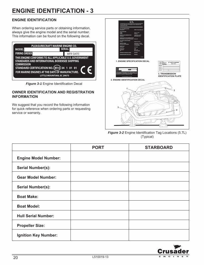
ENGINE IDENTIFICATION - 3ENGINE IDENTIFICATION
When ordering service parts or obtaining information, always give the engine model and the serial number. This information can be found on the following decal.
Figure 3-2 Engine Identifi cation Tag Locations (5.7L)(Typical)
MAKEMODEL SERIALFIRING ORDERTHIS ENGINE CONFORMS TO ALL APPLICABLE U.S.GOVERNMENT STANDARDS FOR MARINE ENGINESIN EFFECT AT DATE OF MANUFACTURE.
LITTLE MOUNTAIN, SC 29075
1. ENGINE SPECIFICATION DECAL
2. ENGINE IDENTIFICATION DECAL
3. TRANSMISSIONIDENTIFICATION PLATE
MODELMARINE
ZF HURTH MARINEARCO ITALY
RATIO IRATIO IIS/N-P/N
5.7LfImportant! See your Owners Manual to insure that specifications for your engine have not changed or been omitted from the specifications listed.
FUEL RECOMMENDATIONSUnleaded 89� (R+M) / 2 Octane Minimum)
FUEL PRESSUREAll TBI� 30 psi +/- 2 psiAll MPI� 40-45 psi
ENGINE OIL RECOMMENDATIONS� 15W-40 Above 50 FAll Engines� 5W-40 Below 50 F
MARINE GEAR OIL RECOMMENDATIONSAll PCM, Warner and Hurth Transmissions� Dexron III
ELECTRICAL SPECIFICATIONS12 Volts� Negative Ground
IGNITION TIMING� Carbureted - 6 BTDCAll Engines @ 1000 RPM� Fuel Injection - 10 BTDC� In Timing ModeSPARK PLUGAll Engines� GAP .045"
ENGINE IDLE� RPMCarburetor� 700 +/- 50EFI� (Not Adjustable)
MAXIMUM CONTINUOUS CRUISE� RPM 3800
MAXIMUM ENGINE SPEED (WOT)� RPM 5000
R143120A
3
2
2
1
Figure 3-1 Engine Identifi cation Decal
PORT STARBOARD Engine Model Number:
Serial Number(s):
Gear Model Number:
Serial Number(s):
Boat Make:
Boat Model:
Hull Serial Number:
Propeller Size:
Ignition Key Number:
OWNER IDENTIFICATION AND REGISTRATION INFORMATION
We suggest that you record the following information for quick reference when ordering parts or requesting service or warranty.
MFR DATE:

21L510019-13
ENGINE IDENTIFICATION - 3
CRUSADERMODEL IDENTIFICATION / ADVISORY
MODEL 50 - 572 V - 0 1 SERIAL 730000
*SERIAL NUMBER I.D.*1st DIGIT INDICATES DECADE ENGINE WAS MANUFACTURED ( 5 = 1990, 6 = 2000, 7 = 2010 )2nd DIGIT INDICATES CALENDAR YEAR ENGINE WAS MANUFACTURED.
1st - 2nd Space: MANUFACTURING CODE
3rd - 5th Space: ENGINE CODE 572 = 5.7L (350 CID LH Carburetor) (GM) 573 = 5.7L (350 CID RH Carburetor) (GM)
6th - 8th Space: DRIVE CONFIGURATION blank - Direct Drive V - V-Drive
9th - 10th Space: SPECIFICATION CODE
22 L510019-13
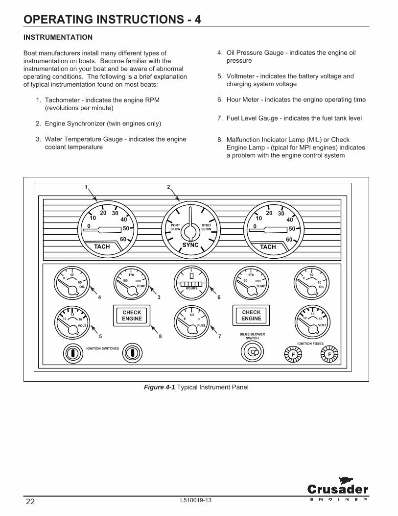
INSTRUMENTATION
Boat manufacturers install many different types of instrumentation on boats. Become familiar with the instrumentation on your boat and be aware of abnormal operating conditions. The following is a brief explanation of typical instrumentation found on most boats:
1. Tachometer - indicates the engine RPM (revolutions per minute)
2. Engine Synchronizer (twin engines only)
3. Water Temperature Gauge - indicates the engine coolant temperature
OPERATING INSTRUCTIONS - 4
4. Oil Pressure Gauge - indicates the engine oil pressure
5. Voltmeter - indicates the battery voltage and charging system voltage
6. Hour Meter - indicates the engine operating time
7. Fuel Level Gauge - indicates the fuel tank level
8. Malfunction Indicator Lamp (MIL) or Check Engine Lamp - (tpical for MPI engines) indicates a problem with the engine control system
TACH
010
20 30
60
5040
TACH
010
20 30
60
5040
SYNC
PORTSLOW
STBDSLOW
BILGE BLOWERSWITCH
IGNITION FUSESIGNITION SWITCHES
F F
VOLT
10 1613
VOLT
10 1613
E
FUEL
HOURS
1/2F
TEMP80
400
OIL200
170100
TEMP200
17010080
400
OIL
CHECKENGINE
CHECKENGINE
8
3
1 2
6
7
4
5
Figure 4-1 Typical Instrument Panel

23L510019-13
ENGINE ALARM SYSTEM
Crusader Marine Engines come equipped with a provision for an audible and/or visual engine alarm system. The purpose of this alarm is to warn the boat operator of a potential problem before an engine failure occurs.
NOTE: Some boat builders may install their own alarm system. It is recommended that the boat owner check with his dealer for an explanation of the particular alarm system installed and how it functions if different than shown.
The alarm comes with a remote warning buzzer which is mounted near the control station so it is audible to the operator at all times. The buzzer will sound when fi rst starting the engine and stop when minimum oil pressure is obtained. This also lets the boat operator know the alarm system is functional.
During normal engine operation, the warning buzzer will sound only when one of the following operation defi ciencies becomes apparent:
1. Engine coolant temperature exceeds 210°F (100°C).
2. Engine oil pressure drops below 10 PSI (69 kPa).
If the warning buzzer sounds during engine operation:
1. Throttle back to idle speed immediately.
2. Quickly observe the water temperature and oil pressure gauges.
3. If low or no oil pressure is indicated, immediately stop engine.
4. If the water temperature gauge indicates an overheating problem, operate at idle speed for a couple of minutes. If the temperature gauge continues to indicate an engine overheat, stop engine.
5. Make needed repairs before restarting engine. Locating and correcting a malfunction immediately will save unnecessary down-time and costly repairs can be prevented.
OPERATING INSTRUCTIONS - 4
Never shift transmission into or out of gear unless throttle is at the idle position. Shifting transmission above 1000 RPM can severely damage boat, transmission and engine.
CAUTION
Figure 4-2 Typical Dash Layout
TACH
010
20 30
60
5040
TACH
010
20 30
60
5040
SYNC
PORTSLOW
STBDSLOW
F F
VOLT
10 1613
VOLT
10 1613
E
FUEL
HOURS
1/2F
TEMP80
400
OIL200
170100
TEMP200
17010080
400
OIL
CHECKENGINE
CHECKENGINE
SHIFT CONTROL THROTTLE
CONTROL
IGNITION FUSES
IGNITION SWITCH
BILGE BLOWER SWITCH
"CHECK ENGINE" LIGHTS
REMOTE CONTROLS
Your boat may be equipped with one of many different types of remote controls available. Ask you dealer for a description and/or demonstration of the particular type installed on your boat.

24 L510019-13
STARTING ENGINE
WARNING
Before starting engine, ventilate the engine compartment by operating the bilge blower for a minimum of fi ve minutes to remove any gas fumes from engine compartment. If boat is not equipped with blower, open engine compartment hatches to ventilate and leave open while starting engine.
OPERATING INSTRUCTIONS - 4
After performing the initial safety checks, proceed as follows to start the engine:
1. Turn the battery switch ON (if equipped).
2. Open the fuel valve.
3. Open the sea cock.
4. Place the remote control in Neutral position. The transmission is equipped with a neutral safety switch, which will not allow the starter motor to operate unless the transmission is in neutral.
5. Position throttle control lever as follows:
- Cold Engine - Pump throttle lever once and return to approximately ¼ throttle.
- Warm Engine - Place throttle lever at approximately ¼ throttle.
- Flooded Engine - Place throttle lever at wide open throttle. Be prepared to quickly decrease engine speed when engine starts.
6. Turn the ignition key to the start position. When the engine starts, release the key.
IMPORTANT: If the engine fails to start within 20-30 seconds, turn the ignition key to the OFF position and allow 2 minutes for the starter motor to cool off before attempting to restart the engine.
IMPORTANT: Do not start the engine without water being supplied to the sea water pick-up pump or sea-water pump impeller will be damaged, and subsequent overheating damage to the engine may result.
IMPORTANT: The following items should be checked before starting the engine, and each time the boat is operated:
• Fuel system for any signs of leakage
• Operation of remote controls and steering
• Engine and transmission oil levels
• Fuel tank levels
• Exhaust system for leaks and tightness of the clamps
• Battery connections and water level in battery cells
• Accessory drive belt
• Cooling system for leaks. If equipped with fresh-water cooling, check coolant level in recovery bottle. Check for signs of water leaks at the exhaust manifolds, risers and elbows (Figure 4-2A). If the water is leaking externally, it is possible that the water is also leaking internally. This could result in internal engine damage. It is very important to service these maintenance items as soon as a problem is indicated.
Figure 4-2A Water Leaks
Check forsigns ofexternal leaks
Check forsigns ofexternal leaks

25L510019-13
Figure 4-3 Throttle Position Setting
OPERATING INSTRUCTIONS - 4
NOTICE: If engine still fails to start, contact your Crusader Marine Engines Dealer for service.
7. Check engine oil pressure immediately after the engine starts. If oil pressure is not within specifi cations (see Engine Specifi cations), immediately stop the engine and determine the cause.
8. Check voltmeter for proper charging system operation.
9. Check the engine and transmission for fuel, oil, water and exhaust leaks.
10. Allow the engine to reach normal operating temperature. Check the temperature gauge to ensure the engine is operating within the normal temperature range. If the temperature is abnormally high, stop the engine immediately and determine the cause.
SHIFTING TRANSMISSION
CAUTION
Never shift the transmission into or out of gear unless the throttle is at the idle position. Shifting the transmission above 1000 RPM can severely damage the boat, transmission and engine.
1. Set the throttle lever at the idle position.
2. Move the transmission lever completely forward to shift into Forward gear.
3. Move the transmission lever completely backward to shift into Reverse gear.
4. Move the transmission lever to the center detent position to shift into Neutral.
Figure 4-4 Shift Control
FULLTHROTTLE
(WOT)
CLEARFLOOD(100%) IDLE
POSITION
NEUTRAL
FORWARDGEAR
REVERSEGEAR
CAUTION
Engine must be properly aligned or vibration, noise and damage to the transmission output shaft seal and bearings may result.

26 L510019-13
STOPPING ENGINE
When returning to the dock, or whenever stopping the engine, bring the throttle back to the idle position. After the engine reaches idle speed, turn the ignition key to the OFF position.
Before stopping the engine after extended high speed operation, allow the engine to idle at 1200 RPM for 3 to 5 minutes to allow the engine to cool down before shutting off the ignition.
After stopping the engine, complete the following:
1. Turn the battery switch OFF, if equipped.
2. Close the fuel valve.
3. Close the sea cock.
4. Flush the cooling system if in a salt water area.
OPERATING INSTRUCTIONS - 4FREEZING TEMPERATURE OPERATION
If the possibility of freezing exists, the cooling system must be protected after the engine is shut off to prevent freeze damage to the engine. Refer to OUT-OF-SEASON STORAGE for draining instructions.
OPERATION IN HIGH DEBRIS AREAS
If the boat is to be operated in high debris areas, a sea strainer should be installed in the water inlet hose to prevent debris from entering the cooling system. The strainer used must be of suffi cient size to allow an adequate supply of water for cooling the engine. A minimum of 30 gallons per minute (114 liters per minute) fl ow rate is required.
27L510019-13
TRIM AND WEIGHT DISTRIBUTION
Trimming of the boat and positioning of the weight (gear and passengers) inside the boat has the following effects on handling:
• Trimming the bow up or shifting weight to the stern (rear).
− Normally used for cruising (running) with a choppy wave condition (following sea) for running at full speed
− Will generally increase speed and engine RPM
− Will cause the bow to bounce in rough water
− In extreme, may cause the boat to porpoise
− When coming off plane, it increases the chances of following wave splashing into the stern of the boat
• Trimming the bow down or shifting the weight to the bow (front)
− Normally used for cruising (running) against a choppy wave condition, acceleration onto plane and operating at slow planing speeds
− Will improve rough water ride and handling
− In extreme, may cause the boat to bow steer (veer back and forth with little control)
CONDITIONS AFFECTING OPERATION - 5
BOAT BOTTOM
To ensure maximum engine performance, fuel economy and boat speed, the bottom of your boat must be kept clean and free of marine growth and barnacles. Marine vegetation may accumulate when the boat is docked and should be removed before operation. If the boat is docked for long periods of time, the water inlets may become clogged with growth and will cause the engine to overheat.
In most areas, it is advisable to coat the boat bottom with antifouling paint to prevent the build-up of marine growth. Contact your dealer for advice on these requirements in your area.
PROPELLER SELECTION
Best all-around performance and maximum engine life is achieved when the engine is propped to run near the top of (but within) the recommended full throttle RPM range with a normal load. See ENGINE SPECIFICATIONS for rated full throttle RPM for your model engine.
Generally, gross weight (total weight of the entire boat, including full fuel and water, optional equipment, passengers and other miscellaneous gear) is one of the major factors and should be one of the primary considerations when selecting a propeller. Other factors to take into consideration are as follows:
• Warmer weather and higher humidity will cause an RPM loss.
• Operating the boat in a higher elevation will cause an RPM loss.
• Operating the boat with an increased load will cause an RPM loss (additional equipment, passengers, etc.).
CAUTION
Prolonged WOT operation will shorten the life of your engine and could cause premature engine failure. See NORMAL CRUISING SPEEDS in SPECIFICATIONS. Problems caused by WOT operation are considered abuse and are not covered under the Crusader Warranty.
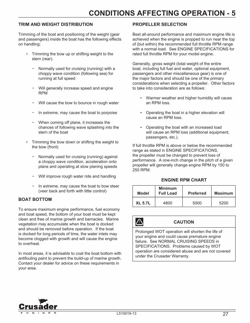
If full throttle RPM is above or below the recommended range as stated in ENGINE SPECIFICATIONS, the propeller must be changed to prevent loss of performance. A one-inch change in the pitch of a given propeller will generally change engine RPM by 150 to 250 RPM.
ENGINE RPM CHART
Minimum Model Full Load Preferred Maximum
XL 5.7L 4800 5000 5200

28 L510019-13
ENGINE BREAK-IN PERIOD - 6The engine oil level should be checked often and oil added when necessary. It must be understood that every internal combustion engine will use a certain amount of oil during operation to act as a lubricating and cooling agent, especially during the break-in period. Oil consumption should decrease and become stabilized after approximately 100 hours of operation.
At the end of your 25-hour break-in period, contact your dealer and have the recommended 25-hour inspection done.
NOTICE: Crusader Marine Engines assumes no responsibility for the costs related to the 25-hour inspection. This is the owner’s responsibility.
The break-in period of your engine is the fi rst 25 hours of operation. Proper engine break-in is essential to achieve maximum performance, longevity and minimum oil consumption. During the break-in period, the following operation guidelines must be adhered to:
• After the engine is thoroughly warmed up, and the boat is underway, open the throttle to wide open throttle until maximum RPM is reached. DO NOT EXCEED MAXIMUM RPM. (RPM should cease climbing after 10 to 20 seconds).
WARNING
Use this procedure ONLY when conditions are such that it can be performed in complete safety.
• Reduce the throttle to 2800 - 3000 RPM, and cruise at or below this speed for 1/2 hour. Reduce the speed to idle. Go to wide open throttle until maximum RPM is reached and operate for approximately 30 seconds. Reduce throttle to 2800-3000 RPM and operate for a few minutes. (Bringing the engine speed from idle to wide open throttle will load the engine and assist in seating the piston rings). This cycle can be repeated from time to time during the fi rst 5 hours of operation, but wide open throttle should not be sustained for more than 1 to 2 minutes.
• During the early part of the break in period, the correct propeller selection can be confi rmed. (With a normal load aboard, the engine’s RPM should reach, but not exceed, the maximum RPM as listed in the specifi cations section).
• During the break in, all gauges should be watched carefully, and the speed should be reduced if abnormal readings become evident.
CAUTION
DO NOT operate at full throttle in neutral at any time, or at sustained full throttle during the fi rst 5 hours of operation. Thereafter, use sustained wide open throttle only in the event of an emergency.
CAUTION
DO NOT attempt to break in any engine by prolong idling, or running at the dock.
29L510019-13
25-HOUR ENGINE INSPECTION - 7After the fi rst 25 hours of operation, it is recommended that the engine be given an inspection. Your boat dealer or a Crusader Premier servicing dealer should be contacted to perform the necessary checks and adjustments to ensure the proper engine performance. The following maintenance should be performed:
• Change the engine oil and fi lter.
• Ignition system - Inspect ignition system and adjust timing, if necessary.
• Replace the primary fuel fi lter.
• Check the engine alignment.
• Inspect the accessory drive belt(s) and check the tension.
• Check all the fl uid levels.
• Check the throttle and the shift cable adjustments and check for freedom of movement.
• Cooling System - Inspect all the hoses for leaks, damage and deterioration. Check all the hose clamps for adequate tightness.
• Exhaust System - Inspect the entire exhaust system for leaks, damage and deterioration. Check all the hose clamps for adequate tightness.
• Battery - Check the electrolyte level and specifi c gravity. Inspect the case for damage. Check the battery cables and connections.
• Engine Assembly - Check for loose, missing or damaged parts. Pay close attention to engine mounts, starter and alternator mounting fasteners.
NOTICE: Crusader Marine Engines assumes no responsibility for the costs related to the 25-hour inspection. This is the owner’s responsibility.
30 L510019-13
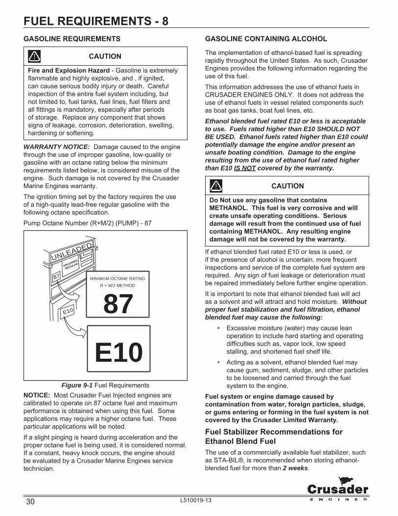
FUEL REQUIREMENTS - 8GASOLINE REQUIREMENTS
Figure 9-1 Fuel RequirementsNOTICE: Most Crusader Fuel Injected engines are calibrated to operate on 87 octane fuel and maximum performance is obtained when using this fuel. Some applications may require a higher octane fuel. These particular applications will be noted.If a slight pinging is heard during acceleration and the proper octane fuel is being used, it is considered normal. If a constant, heavy knock occurs, the engine should be evaluated by a Crusader Marine Engines service technician.
GASOLINE CONTAINING ALCOHOL
The implementation of ethanol-based fuel is spreading rapidly throughout the United States. As such, Crusader Engines provides the following information regarding the use of this fuel.This information addresses the use of ethanol fuels in CRUSADER ENGINES ONLY. It does not address the use of ethanol fuels in vessel related components such as boat gas tanks, boat fuel lines, etc.Ethanol blended fuel rated E10 or less is acceptable to use. Fuels rated higher than E10 SHOULD NOT BE USED. Ethanol fuels rated higher than E10 could potentially damage the engine and/or present an unsafe boating condition. Damage to the engine resulting from the use of ethanol fuel rated higher than E10 IS NOT covered by the warranty.
UNLEADED
REGULARUNLEADED
87
$
MINIMUM OCTANE RATING
R + M/2 METHOD
87
E10E10
CAUTION
Do Not use any gasoline that contains METHANOL. This fuel is very corrosive and will create unsafe operating conditions. Serious damage will result from the continued use of fuel containing METHANOL. Any resulting engine damage will not be covered by the warranty.
If ethanol blended fuel rated E10 or less is used, or if the presence of alcohol is uncertain, more frequent inspections and service of the complete fuel system are required. Any sign of fuel leakage or deterioration must be repaired immediately before further engine operation.It is important to note that ethanol blended fuel will act as a solvent and will attract and hold moisture. Without proper fuel stabilization and fuel fi ltration, ethanol blended fuel may cause the following: • Excessive moisture (water) may cause lean
operation to include hard starting and operating diffi culties such as, vapor lock, low speed stalling, and shortened fuel shelf life.
• Acting as a solvent, ethanol blended fuel may cause gum, sediment, sludge, and other particles to be loosened and carried through the fuel system to the engine.
Fuel system or engine damage caused by contamination from water, foreign particles, sludge, or gums entering or forming in the fuel system is not covered by the Crusader Limited Warranty.
Fuel Stabilizer Recommendations for Ethanol Blend FuelThe use of a commercially available fuel stabilizer, such as STA-BIL®, is recommended when storing ethanol-blended fuel for more than 2 weeks.
CAUTION
Fire and Explosion Hazard - Gasoline is extremely fl ammable and highly explosive, and , if ignited, can cause serious bodily injury or death. Careful inspection of the entire fuel system including, but not limited to, fuel tanks, fuel lines, fuel fi lters and all fi ttings is mandatory, especially after periods of storage. Replace any component that shows signs of leakage, corrosion, deterioration, swelling, hardening or softening.
WARRANTY NOTICE: Damage caused to the engine through the use of improper gasoline, low-quality or gasoline with an octane rating below the minimum requirements listed below, is considered misuse of the engine. Such damage is not covered by the Crusader Marine Engines warranty.The ignition timing set by the factory requires the use of a high-quality lead-free regular gasoline with the following octane specifi cation.Pump Octane Number (R+M/2) (PUMP) - 87

31L510019-13
FUEL REQUIREMENTS - 8PISTON DAMAGE DUE TO DETONATION AND /OR PRE-IGNITIONWARRANTY NOTICE: Engine failure due to detonation and/or pre-ignition is not a defect in material or workmanship. Warranty coverage may not apply to these types of engine failures unless it is proved the failure was caused by a defective part.Detonation, commonly called “spark knock” or “fuel knock,” is abnormal combustion of the fuel which causes the fuel to explode violently within the combustion chamber.Normal burning or combustion in a four-cycle engine starts at the spark plug, and a wave of fl ame moves across the combustion chamber. This results in a smooth pressure rise in the combustion chamber which pushes the piston downward.Detonation starts out as normal combustion with the spark-ignited fl ame progressing across the combustion chamber while applying heat and pressure to the unburned portion of fuel. Then, instead of continuing to burn smoothly and evenly, the last portion of fuel explodes violently, causing overheating of the spark plugs, pistons and valves.Detonation can occur at any engine speed. It is often not detected because of normal operation noises and well-insulated engine compartments. Undetected detonation may result in serious engine damage.The use of low-octane gasoline is one of the most common causes of detonation. Even when using proper gasoline, detonation can occur if engine maintenance is neglected. Some other causes of detonation are: • Improper gasoline quality (octane - R.V.P.) • Improper propeller selection (lugging engine
- inability of engines to reach rated WOT RPM) • Improper initial timing setting (power timing) • Engine overheating. Improper cooling system
operation resulting in overheating condition • Fuel system vapor lock (poor fuel quality, lean
fuel mixture) • Improper carburetor function (water and/or dirt),
(fl oat setting) causing lean mixture • Operating twin engine boat on one engine at high
throttle setting resulting in overload. • Operating engine with dead cylinder, out of
proper tune or wired with improper fi ring order. Defective distributor cap (carbon tracked).
• Excessive exhaust back-pressure caused by restrictive muffl ers and/or collectors or undersized exhaust outlets.

32 L510019-13
OIL REQUIREMENTS - 9ENGINE OIL RECOMMENDATIONS
Use of Supplemental Additives
Engine oils meeting Crusader Marine Engines’ recommendations already contain a balanced additive treatment. The use of supplemental additives which are added to the engine oil by the customer are unnecessary and may be harmful. Crusader Marine Engines does not review, approve or recommend such products.
Synthetic Oils
Synthetic engine oils may be used in Crusader Marine Engines. Synthetic oils must meet the Engine Oil Requirements for Classifi cation and Viscosity listed below. The use of synthetic oil does not permit the extension of oil change intervals.
Engine Oil Requirements
The following chart shows the recommended oil viscosity for various ambient temperature ranges:
Prevailing Ambient Recommended A.P.I. Temperature Classifi cation & Viscosity
Above 50˚F SAE 15W-40 “GF-4/SM”
Below 50˚F SAE 5W-30 “GF-4/SM”
IMPORTANT: The use of oils which contain “solid” additives, non-detergent oils or low quality oils specifi cally are not recommended.
WARRANTY NOTICE: Crusader Marine Engines reserves the right to refuse warranty on part(s) and/or engine(s) damaged by using improper fuels and engine oils.
Oil Change Intervals (Common)
Crankcase oil and oil fi lter change - Recommended intervals:
• Initial oil change - 1st 60 days or 25 hours of operation, whichever occurs fi rst
• Regular oil changes - Every 50 hours of operation or 120 days, whichever occurs fi rst
TRANSMISSION AND “V”-DRIVE OIL REQUIREMENTS
NOTICE: WALTERS “V”-DRIVES ONLY - A low oil pressure warning light is mounted on Walters “V”-Drives. The warning light will stay illuminated until the boat gets underway, and the engine speed increases to suffi cient RPM for the pump to maintain pressure. This normally occurs at approximately 1200 RPM. Extended cruising at low RPM, such as when trolling, is not harmful to the “V”-drive, even though the warning light may remain illuminated.
Recommended A.P.I. Transmission Classifi cation and and “V” Drive Viscosity
Velvet Drive Dexron III Automatic Transmissions and “V” Transmission Fluid (ATF) Drives - All or equivalent
Exxon Spartan EP-68 Walters “V”-Drive or SAE 30 Engine Oil
Dexron III Automatic All Hurth Gear Transmission Fluid (ATF) Transmissions or equivalent
Crusader 4500 SAE 80W-90 “V” - Drive Gear Oil

33L510019-13
ENGINE MAINTENANCE - 10ENGINE MAINTENANCE
Refer to the MAINTENANCE SCHEDULE for a complete listing of required maintenance and the frequency at which it should be performed. Some procedures may be performed by the owner/operator while others should be performed by an authorized Crusader Marine Engines Premier Dealer. Before performing any maintenance or repair procedure not covered in this manual, it is strongly recommended that a Crusader Marine Engines repair manual be purchased and read thoroughly.
CHECKING FLUID LEVELS
Engine Crankcase Oil
CAUTION
Do not overfi ll engine crankcase with oil, as excess oil will be splashed by reciprocating engine parts onto the cylinder walls in greater quantity than the rings can control. The oil, subsequently, will be drawn into the combustion chamber and burned. Continuous operation under these conditions can cause carbon to form on combustion chamber surfaces, which will adversely affect engine performance and may lead to premature engine failure. Splashing or agitation of oil also may cause it to become aerated, which will affect the oil pressure, and may result in internal engine damage from lack of lubrication.
1. Stop the engine if running. Allow approximately 5 minutes for the oil to drain back into the oil pan.
2. Remove the dipstick, wipe it clean, and reinstall it fully into the dipstick tube.
3. Remove the dipstick and observe the oil level. The oil level must be between the “FULL” and “ADD” marks. If the oil level is below the “ADD” mark, add specifi ed oil to bring the level up to, but not over, the “FULL” mark on the dipstick. (Figure 10-1).
WARNING
The machinery space must be closed anytime the engine is running to prevent injury to you or others on board. Never operate the engine with the engine machinery space open or while someone is in the machinery space, either closed or open. Never open the machinery space unless the engine is shut off and the engines’ rotating parts are stationary. Rotating machinery can cause injury and even death if an accident should occur. Extreme care must be exercised if a problem exists that requires operation of the engine with the machinery space open. IT IS RECOMMENDED THAT UNCOVERED ENGINE OPERATION BE ATTEMPTED BY TRAINED AND QUALIFIED SERVICE PERSONNEL ONLY.
Figure 10-1 Engine Oil Dipstick (Typical)
OPERATINGRANGE
ADD MARKFULL MARK
DIPSTICK
DipstickTube
DipstickTube
34 L510019-13
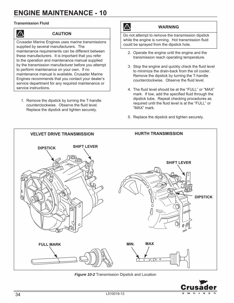
ENGINE MAINTENANCE - 10Transmission Fluid
CAUTION
Crusader Marine Engines uses marine transmissions supplied by several manufacturers. The maintenance requirements can be different between these manufacturers. It is important that you refer to the operation and maintenance manual supplied by the transmission manufacturer before you attempt to perform maintenance on your own. If no maintenance manual is available, Crusader Marine Engines recommends that you contact your dealer’s service department for any required maintenance or service instructions.
1. Remove the dipstick by turning the T-handle counterclockwise. Observe the fl uid level. Replace the dipstick and tighten securely.
2. Operate the engine until the engine and the transmission reach operating temperature.
3. Stop the engine and quickly check the fl uid level to minimize the drain-back from the oil cooler. Remove the dipstick by turning the T-handle counterclockwise. Observe the fl uid level.
4. The fl uid level should be at the “FULL” or “MAX” mark. If low, add the specifi ed fl uid through the dipstick tube. Repeat checking procedures as required until the fl uid level is at the “FULL” or “MAX” mark.
5. Replace the dipstick and tighten securely.
WARNING
Do not attempt to remove the transmission dipstick while the engine is running. Hot transmission fl uid could be sprayed from the dipstick hole.
Figure 10-2 Transmission Dipstick and Location
MIN.FULL MARK
DIPSTICK SHIFT LEVER
VELVET DRIVE TRANSMISSION HURTH TRANSMISSION
SHIFT LEVER
DIPSTICK
MAX

35L510019-13
ENGINE MAINTENANCE - 10LUBRICATION
Throttle Cable
Lubricate pivot points and exposed cable (Figure 10-3) with SAE 30W-30 engine oil.
Figure 10-3 Typical Throttle Cable
Shift Lever
All Velvet Drive Transmissions - Lubricate the detent ball and holes in shift lever (Figure 10-4) with white grease (Lubriplate or equivalent).
Figure 10-4 Transmission Shift Lever - Velvet Drive 5000
Shift Cable
Lubricate pivot points and exposed cable (Figure 10-5) with SAE 30W-30 engine oil.
Figure 10-5 Typical Shift Cable
LUBRICATIONPOINTS
CABLECLIP
BALL JOINT
LUBRICATIONPOINTS
DIPSTICK
SHIFTLEVER

36 L510019-13
ENGINE MAINTENANCE - 10ELECTRICAL SYSTEM CIRCUIT BREAKER
Main Circuit Breaker
Crusader engines are equipped with a circuit breaker which provides electrical overload protection for both engine and instrumentation wiring and components. Should an electrical overload occur, the circuit breaker will open and prevent electrical current fl ow.
When this circuit breaker opens, the cause for the high current draw must be found and corrected. The circuit breaker can be reset by pushing the “Reset” button IN after waiting a few minutes. If the cause of the overload cannot be found, disconnect all accessories which are connected to the main wire harness.
If resetting is still not possible, check the battery and alternator connections and all other harness connectors on the main harness. Check for loose or disconnected lead wires and shorted circuits. Figure 10-6A Typical Electrical System Fuse
IGNITION FUSE
If the engine will not crank, when the ignition key is turned to the START position, fi rst check that the shift lever is in neutral position. If the main circuit breaker is not tripped, check for blown ignition fuse. The ignition fuse may be located on the instrument panel, the fuse holder block or as part of the instrument wiring harness. Check the wiring diagrams supplied from the boat manufacturer for the exact location.
The electrical system wiring and connectors should be checked periodically for loose or dirty connections and damaged wiring. If electrical components or wiring show signs of corrosion, deterioration or damage, consult a Crusader Marine Engines Premier dealer to make necessary repairs.
WARNING
Always disconnect battery cables from battery when servicing electrical system to prevent personal injury and to prevent damage to electrical system components.
Fuse
ELECTRICAL SYSTEM FUSES
Crusader engines utilize a fuse to protect the fuel pump. The fuse is mounted in the main engine harness, in a weather-tight cover, located near the throttle cable bracket.
The fuse is a 5A, slow blow, Buss type fuse. Should this fuse open, the fuel pump will not operate. Check wiring for loose connections and shorted wires. If unable to resume normal fuel pump operation, after replacement of the fuse, it is possible the electric fuel pump has failed internally. Contact your Crusader Premier dealer for proper replacement of the fuel pump.
Figure 10-6 Typical Electrical System Circuit Breaker
CircuitBreaker
ELECTRICAL SYSTEM WIRING AND CONNECTORS

37L510019-13
ENGINE MAINTENANCE - 10BATTERY
WARNING
Battery electrolyte is a corrosive acid and should be handled with care. If electrolyte is spilled or splashed on any part of the body, IMMEDIATELY fl ush the exposed area with liberal amounts of water and obtain medical aid as soon as possible. Safety glasses and rubber gloves are recommended when handling batteries or fi lling with electrolyte.
WARNING
Hydrogen gases that escape from the battery when charging are highly explosive. Do not use jumper cables and a booster battery to start the engine. Do not recharge a weak battery in the boat. Remove the battery from the boat and recharge in a well ventilated area away from fuel vapors, sparks and open fl ames.
Follow maintenance instructions and warnings as supplied by the battery manufacturer. If this information is not available, follow these guidelines for the proper battery care.
• Do not operate the engine with an open battery circuit, as this may cause damage to the alternator. Make sure that all connections are clean and secure.
• When removing the battery cables, always remove negative (-) cable fi rst, and then remove the positive (+) cable. When installing battery cables, install the positive (+) cable fi rst, then install the negative (-) cable.
• Periodically check the battery for signs of corrosion, frayed battery leads or cracked case. Repair or replace as necessary.
• Periodically check the electrolyte level. Add distilled water to bring up to the proper levels.
FRESH-WATER COOLING SYSTEM SACRIFICIAL ZINC ANODE
Located in the raw water side of the heat exchanger and in the bottom of the oil cooler are zinc anodes which are marked by decals. To check, remove the plug and visually check the condition of the zinc rod. The length of the zinc rod when new is approximately 1.5 inches. If more than one half of the zinc is gone, replace with a new zinc anode.
Different geographic locations and water make-up can result in either high or low sacrifi cial requirements. A high rate of zinc anode consumption should also alert the owner to a possibility of an improperly wired boat accessory, which would require complete checking by qualifi ed service personnel.
Figure 10-7 Zinc Anode Location F.W.C. Heat Exchanger (Typical)
ZINCANODE
IMPORTANT: Your engine is designed to work with the standard electronics installed in your boat. If you add other electrical components or accessories, you could change the way the fuel injection controls your engine or the overall electrical system functions. Before adding electrical equipment, consult your dealer. If you don’t, your engine may not perform properly.
CAUTION
Add-on equipment may adversely affect the alternator output or overload the electrical system. Any damage caused as a result will not be covered by, and may void, your warranty.

38 L510019-13
ENGINE MAINTENANCE - 10CHECKING COOLANT LEVEL
WARNING
Do not remove cooling system fi ller cap when the engine is hot. Allow the engine to cool and then remove the pressure cap slowly, allowing the pressure to vent. Hot coolant, under pressure, may discharge violently and cause severe burns.
DeGas Bottle
The “see-through” degas bottle is connected to the heat exchanger by a small hose. The degas bottle collects coolant that expands with rising temperature, and would otherwise overfl ow from the system. Coolant level should be at or slightly above the “MAX” mark on the bottle when the system is cold. Coolant should be added ONLY to the bottle when the system cools.
Figure 10-8 Checking Coolant Level (Typical)
FLUSHING COOLING SYSTEM - SEA-WATER SECTION
To prevent silt and/or salt build-up in the cooling system (fresh or raw-water cooled), fl ush the sea-water section of the cooling system with fresh water at specifi ed intervals.
CAUTION
Do not operate the engine without water being supplied to the sea-water pump. The sea-water pump impeller may be damaged and subsequent overheating damage may result.
CAUTION
Do not run the engine above 1500 RPM when fl ushing. Suction created by the sea-water pump may collapse the fl ushing hose, causing the engine to overheat. Watch the temperature gauge while fl ushing to ensure the engine does not overheat.
Figure 10-9 Typical Sea-Water Inlet
INLETHOSE
CLOSESEACOCKBEFORE
REMOVINGINLETHOSE
ATTACHFLUSHINGADAPTER
HERE
1. Close sea cock and remove inlet hose at seawater pump.
2. Using an appropriate connector, connect a hose between sea water pump and fresh water tap. Open water tap about ½ of maximum.
3. Start engine and operate at idle speed in neutral for about 10-15 minutes, or until discharge water is clear. Stop engine.
4. Shut off water and remove fl ushing connector from pump inlet. Reconnect inlet hose, tightening hose clamp securely.
5. Open sea cock prior to restarting engine.
DEGASBOTTLE
MAXMIN

39L510019-13
ENGINE MAINTENANCE - 10TESTING COOLANT FOR ALKALINITY
It is recommended that the coolant in the fresh-water section be tested each year for alkalinity. Coolant that is not alkaline has lost the effectiveness of its rust inhibitors, which can lead to internal corrosion and cooling system problems. It is recommended to replace the extended life engine coolant, known as DEX-COOL™, in the system every fi ve years to prevent a build-up of harmful chemicals within the fresh-water system.
1. Obtain red litmus paper from a local supplier (drugstore, laboratory, etc..).
2. Remove the pressure cap from the Degas Bottle and insert one end of the litmus paper into the coolant.
3. If red litmus paper turns blue, coolant is alkaline and does not need to be replaced. If the litmus paper remains red, the coolant is not alkaline and must be replaced.
DRAINING FRESH-WATER COOLING SYSTEM
NOTICE: To protect the environment, dispose of coolant properly. Check your local restrictions for proper disposal instructions of removed coolant.
NOTICE: Refer to cooling system water fl ow diagrams for drain locations.
1. Remove the following drain plugs to drain coolant from the fresh-water cooling system:
− Drain plug on heat exchange (center)
− The hose and/or drain plugs from the fi tting on the bottom of the exhaust manifolds (one on each side)
− Drain plugs from heated risers (two each side, if equipped)
− Drain plugs on the cylinder block (one on each side)
2. Remove the large hose from the engine block water circulating pump.
3. After system has drained completely, coat all the drain plugs with PerfectSeal (or equivalent) and reinstall in the proper locations. Reinstall the hose(s) on the water circulating pump and the exhaust manifolds and tighten the clamps securely.
WARNING
Do not remove cooling system fi ller cap when the engine is hot. Allow the engine to cool and then remove the pressure cap slowly, allowing the pressure to vent. Hot coolant, under pressure, may discharge violently and cause severe burns.
WARNING
Do not remove cooling system fi ller cap when the engine is hot. Allow the engine to cool and then remove the pressure cap slowly, allowing the pressure to vent. Hot coolant, under pressure, may discharge violently and cause severe burns.
Figure 10-10 Draining Engine Circulating Pump (5.7L)Remove large HOSE, or DRAIN PLUG (if equipped)

40 L510019-13
ENGINE MAINTENANCE - 10FILLING FRESH-WATER COOLING SYSTEMA new extended life engine coolant known as DEX-COOL™ is used in your engine(s). It is imperative to note the following about DEX-COOL™ engine coolant: • IT IS PINK IN COLOR TO DISTINGUISH IT
FROM CONVENTIONAL COOLANT. • THE SERVICE CHANGE INTERVAL ON
ENGINES BUILT WITH DEX-COOL™ IS 5 YEARS.
• TO MAINTAIN FULL CORROSION PROTECTION DURABILITY, DEX-COOL™ MUST NOT BE MIXED WITH CONVENTIONAL (CONTAINING SILICATE) ENGINE COOLANTS.
• DEX-COOL™ IS AN ETHYLENE GLYCOL BASED PRODUCT, THEREFORE, BOIL AND FREEZE PROTECTION ARE MEASURED IN THE SAME FASHION AS CONVENTIONAL COOLANTS.
TO FULLY REALIZE ITS MANY ADVANTAGES, DEX-COOL™ MUST NEVER BE MIXED WITH CONVENTIONAL COOLANTS.DEX-COOL™ can become contaminated by inadvertently topping-off with conventional coolant, adding conventional coolant to the system or even if fi ll/drain containers are shared between coolants. If contamination occurs, the cooling system must be immediately drained and fl ushed, and refi lled with DEX-COOL™. No short-term damage will occur, however, the service interval will be reduced from 5 years to 2 years.The fresh-water cooling side of the cooling system must be fi lled with a 50/50 mixture of DEX-COOL™ (or equivalent, which meets GM6277M) extended life antifreeze and water solution.IMPORTANT: More than 50% antifreeze solution can contribute to an overheating condition.IMPORTANT: If the engine is being placed in winter storage, the fresh-water cooling section must be fi lled with the correct type of coolant and water solution, properly mixed, to protect the engine to the lowest temperature to which it will be exposed. 1. Make sure that all drain plugs are properly
installed. 2. Remove the pressure cap from the Degas Bottle,
located on the heat exchanger. 3. Fill the system with antifreeze solution until
the system is fi lled. See ENGINE FLUID CAPACITIES for system capacities.
Figure 10-11 F.W.C. Fill Riser Location (Typical)
Figure 10-12 Filling F.W.C. System (Typical)
4. Start the engine and operate at idle speed (800-1000 RPM) to purge any air from the system. When the coolant level remains constant in the fi ller riser, install the pressure cap on the riser.
5. Add additional coolant into the Degas Bottle to the “MAX” level.
6. Continue to run the engine until it reaches normal operating temperature. Check the Degas Bottle for the proper level and add coolant if necessary.
NOTICE: It is not necessary to remove pressure cap to check coolant levels. Check Degas Bottle daily and keep fi lled to the cold, or “MAX”, level indicated on the tank.
PRESSURECAP
ANTIFREEZESOLUTION

41L510019-13
ENGINE MAINTENANCE - 10CLEANING SEA-WATER SECTION OF HEAT EXCHANGER - FRESH-WATER COOLED MODELS ONLY
The sea-water section of the heat exchanger should be cleaned whenever there is a noticeable decrease in cooling effi ciency. You may use the following procedure for cleaning, or, if the build-up of scale and mineral deposits is heavy, it is recommended that the heat exchanger be removed and taken to a repair facility to be boiled out (such as a radiator repair facility).
1. Remove the bolts securing the heat exchanger end plates. Remove the end plates and gaskets.
2. Clean the water passages in the heat exchanger by inserting a suitable-size wire brush into each passage. Use compressed air to blow out loose particles.
3. Clean the gasket surfaces on the end plates and the heat exchanger. Apply PerfectSeal to both sides of the new gaskets. Install the end plates and the new gaskets onto the heat exchanger. Install the bolts and tighten securely.
4. Start the engine and inspect for leaks.
Figure 10-13 Heat Exchanger and End Plate Removal(Typical)
HEAT EXCHANGER
THERMOSTAT HOUSING
COOLANT DRAIN PLUG
GASKET
PLATEBOLT
WARNING
Extreme caution must be exercised when servicing the fuel system and/or replacing fuel fi lter. Gasoline is extremely fl ammable and highly explosive under certain conditions. Be sure the ignition key is off and do not smoke or allow open fl ame in the area while servicing. Wipe up any spilled fuel immediately.
WARNING
Make sure that there are no fuel leaks before closing the engine hatch.
FUEL SYSTEM DESCRIPTION
ELECTRIC FUEL PUMP
Crusader Marine Engines are equipped with an electric fuel pump mounted on the front right side of the engine, behind the sea water pump and in front of the engine mount. The operation of the pump is controlled by an oil pressure switch located in the main oil pressure galley. Loss of oil pressure will cause the switch to open and halt the fl ow of electrical power to the fuel pump. The fuel pump circuit is also energized when the starter motor is engaged, so fuel will be available to the carburetor upon engine startup. Once the engine starts and oil pressure is achieved, the pump will continue to operate.
WARNING
Visually inspect unit for fuel leaks before operating the engine. If fuel leaks are present, DO NOT operate the engine, contact your Crusader Premier service center immediately.
WARNING
Make sure there are no fuel leaks before closing the engine hatch.
Priming Fuel System
When fi rst starting the engine, or after changing fuel fi lters, it may be necessary to prime the fuel system. Priming the fuel system may be accomplished by cranking the engine until it starts or 30 seconds elapse. If the engine does not start, wait 2 minutes and repeat the priming procedure.

42 L510019-13
ENGINE MAINTENANCE - 10
FLAME ARRESTOR
At specifi ed intervals, the fl ame arrestor should be checked for blockage caused by dirt or other foreign material.
Loosen the screw(s) securing the fl ame arrestor cover and fl ame arrestor to the carburetor. Remove the fl ame arrestor and crankcase vent hose(s). Clean the fl ame arrestor with solvent and dry with compressed air. Reinstall the fl ame arrestor and cover then tighten the retaining screw(s) securely.
Figure 10-14 Flame Arrestor - 5.7L (Typical)
FLAMEARRESTOR
CARBURETOR
WARNING
Engine must be shut OFF and the ignition key removed before inspecting the drive belt(s). The drive belt(s) should be checked periodically for condition and tension. If the belt(s) shows signs of cracking, glazing or deterioration, replace with new belt(s).
DRIVE BELT INSPECTIONInspect the drive belt for excessive wear, shredding or missing sections.Inspect the drive belt for contamination from excessive dirt, oil, coolant or other substances that may effect the drive belt operation.If a problem is found, replace the belt after inspecting the following items: • All pulleys and tensioners for signs of
misalignment • All pulleys and tensioners for signs of rust or
other damage • Bent pulleys or tight bearings in the engine water
circulation pump, sea-water pump and alternator
5.7L ACCESSORY DRIVE BELTThe Crusader 5.7L engine uses a single serpentine belt to drive the engine water circulation pump, sea-water pump and the alternator.Serpentine Belt (LH Rotation) P/N - R066028Serpentine Belt (RH Rotation) P/N - R066029A
DRIVE BELT REPLACEMENT (5.7L) 1. Note the routing of the belt before removing. 2. Using a 15 mm box wrench or socket, turn the
belt tensioner to relieve the tension on the belt. Slide the belt off of the pulleys. Release the tensioner slowly to prevent the tensioner from snapping against its stop, and possibly causing damage to the tensioner.
3. Slide the new belt onto the pulleys using the same routing as noted prior to removal.
4. Compress the belt tensioner, and slide the belt over the tensioner pulley. Release the tension slowly to tension the belt.
SERVICING RAW WATER PUMP IMPELLER (5.7L)The raw water pump impeller should be serviced every 50 hours, or once a year, whichever occurs fi rst. See Maintenance Schedule.

43L510019-13
ENGINE MAINTENANCE - 10
Figure 10-16 Belt Tensioner (5.7L)
Figure 10-15 5.7L Accessory Drive Belt Confi guration(Left Hand Rotation)
Locations “A” (Figure 10-15) are access holes in order to loosen the raw water pump attaching bolts. The bolts are secured in the pump by O-rings, and will not fall out during removal.Torque the raw water pump housing attaching bolts to 8.5-9 ft.lbs. (11.5-12 N-M), when re-installing the impeller.
BeltTensioner
CirculationPump
Raw WaterPump
CrankshaftPulley
Alternator
A
Figure 10-15A 5.7L Accessory Drive Belt Confi guration(Right Hand Rotation)
BeltTensioner
CirculationPump
Raw WaterPump
CrankshaftPulley
Alternator
BELT ROUTING - RHBelt Idler
CHANGING OILS
WARNING
IMPORTANT: The Federal Water Pollution Control Act prohibits the discharge of oil or oily waste into or upon the navigable waters and continuous zone of the United States, if such discharge causes a fi lm or sheen upon, or discoloration of the surface of the water, or causes sludge or emulsion beneath the surface of the water. Violators are subject to a penalty of $5,000.00.
Refer to the MAINTENANCE SCHEDULE for oil change intervals. The engine and transmission oils should be changed prior to placing the boat into storage.
The transmission oil change should be performed by an authorized dealer, at specifi ed intervals.
IMPORTANT: Change the engine oil when the engine is warm from operation. Warm oil fl ows more freely, and allows more foreign material and impurities to be removed.
1. With the engine at normal operating temperature, remove the dipstick and install a crankcase oil pump onto the dipstick tube (Figure 10-17). Insert the discharge hose into a suitable container. Pump the oil from the engine until the crankcase is empty. Remove the oil pump from the dipstick tube.
2. Remove the oil fi lter by turning it counterclockwise, using an oil fi lter wrench if necessary. Discard the old fi lter and sealing ring.
Figure 10-17 Engine Oil Removal
OIL PUMP
CONTAINER
DIPSTICK

44 L510019-13
ENGINE MAINTENANCE - 10 3. Coat the sealing ring, on the new fi lter, with a
light coating of clean engine oil. Install the oil fi lter securely by hand. DO NOT overtighten.
4. Fill the engine with the recommended oil, see OIL REQUIREMENTS, through the oil fi ll location on the valve cover (Figure 10-18).
Figure 10-18 Engine Oil Fill (Typical)
5. Start the engine and operate for 5 minutes to circulate the oil throughout the engine. Check entire system for leaks, especially around the oil fi lter.
6. Stop the engine and wait 5 minutes to allow the oil to completely drain down. Check the oil level and add oil, if needed, to bring the engine oil to the proper level.
OIL FILLCAP
ENGINE ALIGNMENT
CAUTION
Engine must be properly aligned, or vibration, noise and damage to the transmission output shaft, oil seal and bearings may result.
IMPORTANT: On boats with remote “V” -Drives, refer to the “V”-Drive manufacturer’s instructions for the correct alignment of the drive shaft between the “V” -Drive and the transmission.
IMPORTANT: Engine alignment MUST BE RECHECKED with the boat in the water, fuel tanks full and with a normal load on the boat.
Engine must be aligned so that the transmission and the propeller shaft coupling center lines are aligned, and coupling faces are parallel within 0.003 in. (0.07 mm). This applies to installations with solid couplings, as well as fl exible couplings.
1. Check the mating surfaces on the transmission and the propeller shaft couplings. Make sure they are clean and fl at. (Figures 10-19, 10-20)
Figure 10-19 Shaft Mating Surface Check - 8 Degree Down Angle

45L510019-13
ENGINE MAINTENANCE - 10
Figure 10-20 Shaft Mating Surface Check - “V” Drives
2. Center the propeller shaft in the shaft log as follows (Figure 10-21):
• Push down and then lift the propeller shaft as far as it will move, then place the shaft in the middle of the movement.
• Move the shaft to the port and then to the starboard as far as the shaft will move, then place the shaft in the middle of the movement.
• With the propeller shaft in the middle of the shaft log, align the engine to the shaft.
3. Check that the coupling center lines align by butting the propeller shaft coupling against the transmission coupling (Figure 10-22). The shoulder on the propeller shaft coupling face should engage the recess on the transmission coupling face, with no resistance.
IMPORTANT: Offset misalignment conditions must be corrected prior to checking for angular misalignment.
NOTICE: Some propeller shaft couplings may not have a shoulder on the mating surface. On these installations, use a straight edge to check the center line alignment. (Figure 10-23)
4. OFFSET ALIGNMENT: If the coupling center lines are not aligned, adjust the engine mounts as follows:
• UP or DOWN OFFSET ADJUSTMENT: Loosen the lag bolt 1/4 turn. Use the mount adjusting tool or a 3/8 in. (0.95 cm) or ½ (1.27 cm) diameter rod through both sides of the adjusting sleeve to turn (Figure 10-24). Turn the adjusting sleeve in the direction required to raise or lower the engine. After the adjustment is complete, tighten the lag bolt.
IMPORTANT: Both front mount (or rear mount) adjusting sleeves must be turned equally to keep the engine level from side to side.
• LEFT or RIGHT OFFSET ADJUSTMENT: Loosen the trunnion clamping bolt and the nut on all four mounting brackets. Move the engine to the left or right, as necessary, to obtain the proper alignment. (Figure 10-25) After adjustment is complete, tighten all trunnion bolts.
IMPORTANT: The large diameter of the mount trunnion MUST NOT extend over 1.0 in. (25.4 mm) from the mounting brackets on any of the mounts.
Figure 10-21 Centering Prop Shaft
B
B
A
A
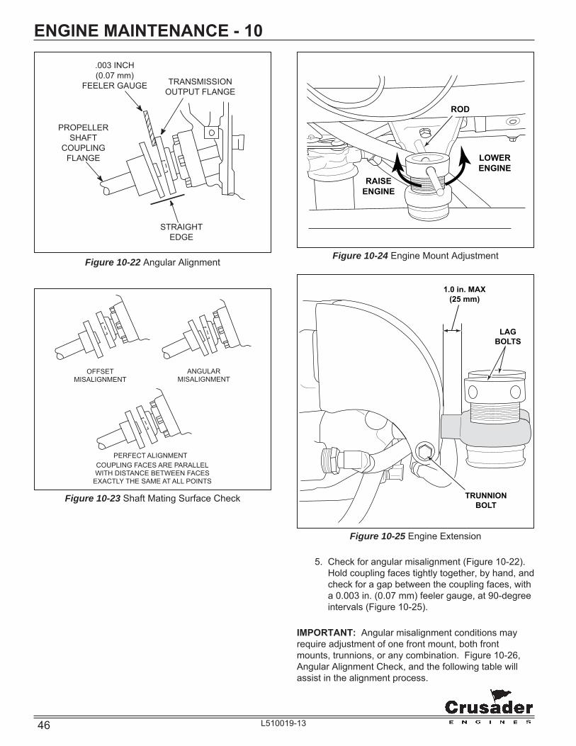
46 L510019-13
ENGINE MAINTENANCE - 10
Figure 10-22 Angular Alignment
STRAIGHTEDGE
TRANSMISSION OUTPUT FLANGE
.003 INCH(0.07 mm)
FEELER GAUGE
PROPELLERSHAFT
COUPLINGFLANGE
Figure 10-23 Shaft Mating Surface Check
OFFSETMISALIGNMENT
ANGULARMISALIGNMENT
PERFECT ALIGNMENTCOUPLING FACES ARE PARALLEL WITH DISTANCE BETWEEN FACES
EXACTLY THE SAME AT ALL POINTS
Figure 10-25 Engine Extension
Figure 10-24 Engine Mount Adjustment
ROD
LOWERENGINE
RAISEENGINE
TRUNNIONBOLT
1.0 in. MAX(25 mm)
LAGBOLTS
5. Check for angular misalignment (Figure 10-22). Hold coupling faces tightly together, by hand, and check for a gap between the coupling faces, with a 0.003 in. (0.07 mm) feeler gauge, at 90-degree intervals (Figure 10-25).
IMPORTANT: Angular misalignment conditions may require adjustment of one front mount, both front mounts, trunnions, or any combination. Figure 10-26, Angular Alignment Check, and the following table will assist in the alignment process.

47L510019-13
ENGINE MAINTENANCE - 10 ANGULAR MOUNT MISALIGNMENT ADJUST
“A” Both Quadrant Front Mounts
“B” Trunnion Quadrant Adjustment
“LC” Right Front Quadrant Mount
“RC” Left Front Quadrant Mount
• UP or DOWN ANGULAR ADJUSTMENT: Loosen the lag bolt 1/4 turn. Use the mount adjusting tool or a 3/8 in. (0.95 cm) or ½” (1.27 cm) diameter rod through both sides of the adjusting sleeve to turn (Figure 10-24). Turn the adjusting sleeve in the direction required to raise or lower the engine. After the adjustment is complete, tighten the lag bolt.
• LEFT or RIGHT ANGULAR ADJUSTMENT: Loosen the trunnion clamping bolt and the nut on all four mounting brackets. Move the engine to the left or right, as necessary, to obtain the proper alignment. (Figure 10-25) After adjustment is complete, tighten all trunnion bolts.
Figure 10-26 Angular Alignment Check
A
A
B B
RC
RC
LC
LC
6. After the engine has been properly aligned, secure the engine mounts.
7. Connect the propeller shaft coupling to the transmission coupling. Tighten the coupling attaching bolts and nuts to the correct specifi cations.
FASTENER TORQUE SPECIFICATIONS Location Lb-Ft (N.m)
Engine Mount to Stringer Securely
Propeller 50 (68)
Trunnion Bolts 45 (61)

48 L510019-13
ENGINE MAINTENANCE - 10ENGINE MAINTENANCE LOG
Operating Date Maintenance/Repair Hours
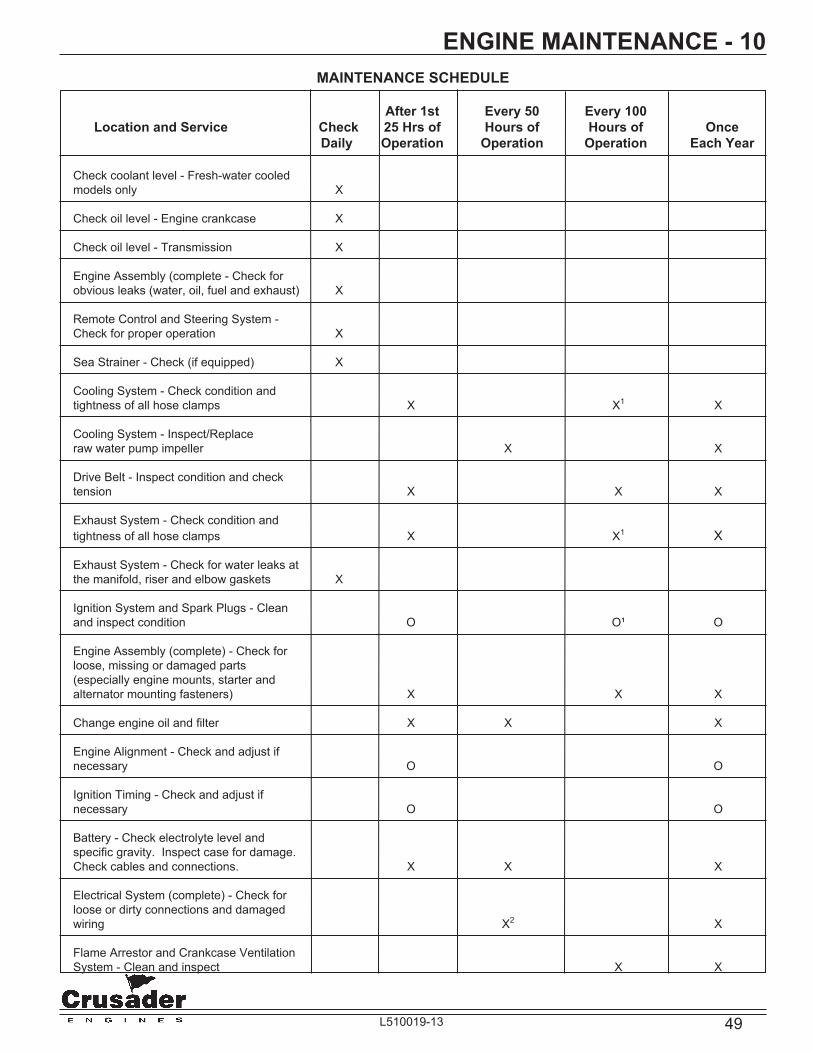
49L510019-13
ENGINE MAINTENANCE - 10MAINTENANCE SCHEDULE
After 1st Every 50 Every 100 Location and Service Check 25 Hrs of Hours of Hours of Once Daily Operation Operation Operation Each Year
Check coolant level - Fresh-water cooled models only X
Check oil level - Engine crankcase X
Check oil level - Transmission X
Engine Assembly (complete - Check for obvious leaks (water, oil, fuel and exhaust) X
Remote Control and Steering System - Check for proper operation X
Sea Strainer - Check (if equipped) X
Cooling System - Check condition and tightness of all hose clamps X X1 X
Cooling System - Inspect/Replace raw water pump impeller X X
Drive Belt - Inspect condition and check tension X X X
Exhaust System - Check condition and tightness of all hose clamps X X1 X
Exhaust System - Check for water leaks at the manifold, riser and elbow gaskets X
Ignition System and Spark Plugs - Clean and inspect condition O O¹ O
Engine Assembly (complete) - Check for loose, missing or damaged parts (especially engine mounts, starter and alternator mounting fasteners) X X X
Change engine oil and fi lter X X X
Engine Alignment - Check and adjust if necessary O O
Ignition Timing - Check and adjust if necessary O O
Battery - Check electrolyte level and specifi c gravity. Inspect case for damage. Check cables and connections. X X X
Electrical System (complete) - Check for loose or dirty connections and damaged wiring X2 X
Flame Arrestor and Crankcase Ventilation System - Clean and inspect X X
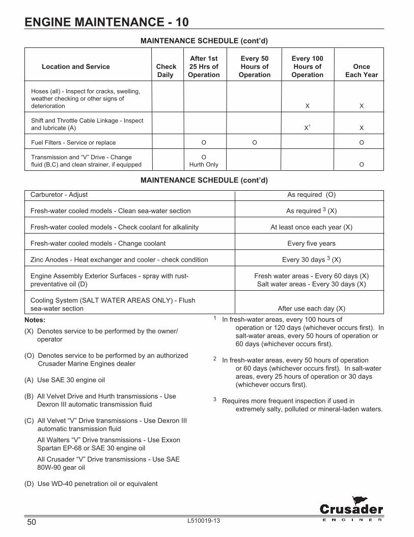
50 L510019-13
ENGINE MAINTENANCE - 10MAINTENANCE SCHEDULE (cont’d)
After 1st Every 50 Every 100 Location and Service Check 25 Hrs of Hours of Hours of Once Daily Operation Operation Operation Each Year
Hoses (all) - Inspect for cracks, swelling, weather checking or other signs of deterioration X X
Shift and Throttle Cable Linkage - Inspect and lubricate (A) X1 X
Fuel Filters - Service or replace O O O
Transmission and “V” Drive - Change O fl uid (B,C) and clean strainer, if equipped Hurth Only O
MAINTENANCE SCHEDULE (cont’d)
Carburetor - Adjust As required (O)
Fresh-water cooled models - Clean sea-water section As required 3 (X)
Fresh-water cooled models - Check coolant for alkalinity At least once each year (X) Fresh-water cooled models - Change coolant Every fi ve years
Zinc Anodes - Heat exchanger and cooler - check condition Every 30 days 3 (X)
Engine Assembly Exterior Surfaces - spray with rust- Fresh water areas - Every 60 days (X) preventative oil (D) Salt water areas - Every 30 days (X)
Cooling System (SALT WATER AREAS ONLY) - Flush sea-water section After use each day (X)
Notes:(X) Denotes service to be performed by the owner/
operator
(O) Denotes service to be performed by an authorized Crusader Marine Engines dealer
(A) Use SAE 30 engine oil
(B) All Velvet Drive and Hurth transmissions - Use Dexron III automatic transmission fl uid
(C) All Velvet “V” Drive transmissions - Use Dexron III automatic transmission fl uid
All Walters “V” Drive transmissions - Use Exxon Spartan EP-68 or SAE 30 engine oil
All Crusader “V” Drive transmissions - Use SAE 80W-90 gear oil
(D) Use WD-40 penetration oil or equivalent
1 In fresh-water areas, every 100 hours of operation or 120 days (whichever occurs fi rst). In salt-water areas, every 50 hours of operation or 60 days (whichever occurs fi rst).
2 In fresh-water areas, every 50 hours of operation or 60 days (whichever occurs fi rst). In salt-water areas, every 25 hours of operation or 30 days (whichever occurs fi rst).
3 Requires more frequent inspection if used in extremely salty, polluted or mineral-laden waters.
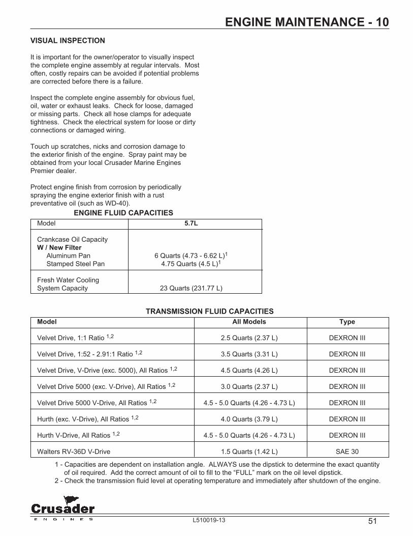
51L510019-13
VISUAL INSPECTION
It is important for the owner/operator to visually inspect the complete engine assembly at regular intervals. Most often, costly repairs can be avoided if potential problems are corrected before there is a failure.
Inspect the complete engine assembly for obvious fuel, oil, water or exhaust leaks. Check for loose, damaged or missing parts. Check all hose clamps for adequate tightness. Check the electrical system for loose or dirty connections or damaged wiring.
Touch up scratches, nicks and corrosion damage to the exterior fi nish of the engine. Spray paint may be obtained from your local Crusader Marine Engines Premier dealer.
Protect engine fi nish from corrosion by periodically spraying the engine exterior fi nish with a rust preventative oil (such as WD-40).
ENGINE MAINTENANCE - 10
ENGINE FLUID CAPACITIES
TRANSMISSION FLUID CAPACITIES
Model 5.7L
Crankcase Oil Capacity W / New Filter Aluminum Pan 6 Quarts (4.73 - 6.62 L)1 Stamped Steel Pan 4.75 Quarts (4.5 L)1
Fresh Water Cooling System Capacity 23 Quarts (231.77 L)
Model All Models Type
Velvet Drive, 1:1 Ratio 1,2 2.5 Quarts (2.37 L) DEXRON III
Velvet Drive, 1:52 - 2.91:1 Ratio 1,2 3.5 Quarts (3.31 L) DEXRON III
Velvet Drive, V-Drive (exc. 5000), All Ratios 1,2 4.5 Quarts (4.26 L) DEXRON III
Velvet Drive 5000 (exc. V-Drive), All Ratios 1,2 3.0 Quarts (2.37 L) DEXRON III
Velvet Drive 5000 V-Drive, All Ratios 1,2 4.5 - 5.0 Quarts (4.26 - 4.73 L) DEXRON III
Hurth (exc. V-Drive), All Ratios 1,2 4.0 Quarts (3.79 L) DEXRON III
Hurth V-Drive, All Ratios 1,2 4.5 - 5.0 Quarts (4.26 - 4.73 L) DEXRON III
Walters RV-36D V-Drive 1.5 Quarts (1.42 L) SAE 30
1 - Capacities are dependent on installation angle. ALWAYS use the dipstick to determine the exact quantity of oil required. Add the correct amount of oil to fi ll to the “FULL” mark on the oil level dipstick. 2 - Check the transmission fl uid level at operating temperature and immediately after shutdown of the engine.

52 L510019-13
ENGINE MAINTENANCE - 10FILTER REQUIREMENTS
Description Part No.
Oil Filter (remote-mounted) 22679
Kit, Transmission Oil Filter (ZF) RP077011
Water Separator/Fuel Filter See Dealer
ON-BOARD PARTS KITS Description Part No.
ON-BOARD PARTS KIT 5.7L (LH) ‘04 SERPENTINE RK173094 Box, On-Board 22433 Belt, Serpentine R066028 Coil, Ignition Breakerless R117004 Resistor, Ignition R119001 Relay, Starter R130011A SparkPlug, Set, (Platinum) RP030010 Impeller, Raw Water Pump RP061022 Module, Ignition RP116022 Tune-Up Kit, Cap and Rotor RP173081A
ON-BOARD PARTS KIT 5.7L (RH) ‘04 SERPENTINE RK173094A Box, On-Board 22433 Belt, Serpentine R066029A Coil, Ignition Breakerless R117004 Resistor, Ignition R119001 Relay, Starter R130011A SparkPlug, Set, (Platinum) RP030010 Impeller, Raw Water Pump RP061022 Module, Ignition RP116022 Tune-Up Kit, Cap and Rotor RP173081A
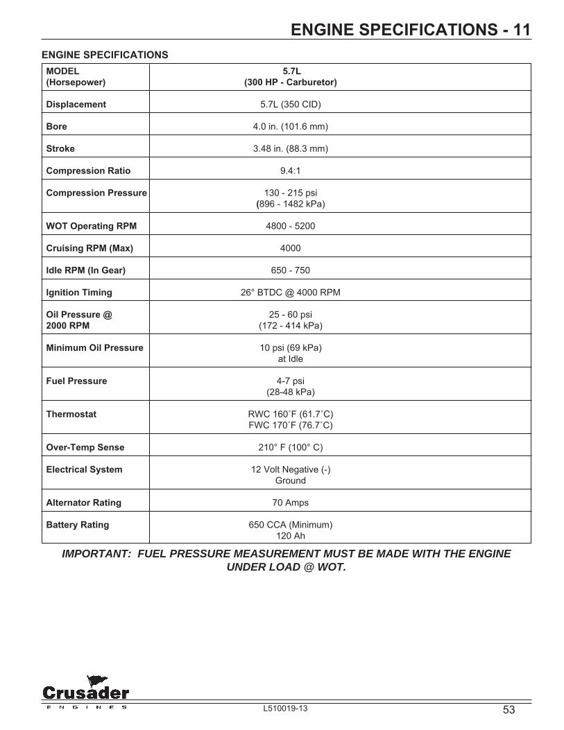
53L510019-13
ENGINE SPECIFICATIONS - 11
MODEL 5.7L (Horsepower) (300 HP - Carburetor)
Displacement 5.7L (350 CID)
Bore 4.0 in. (101.6 mm)
Stroke 3.48 in. (88.3 mm)
Compression Ratio 9.4:1
Compression Pressure 130 - 215 psi (896 - 1482 kPa)
WOT Operating RPM 4800 - 5200
Cruising RPM (Max) 4000
Idle RPM (In Gear) 650 - 750
Ignition Timing 26° BTDC @ 4000 RPM
Oil Pressure @ 25 - 60 psi 2000 RPM (172 - 414 kPa)
Minimum Oil Pressure 10 psi (69 kPa) at Idle Fuel Pressure 4-7 psi (28-48 kPa)
Thermostat RWC 160˚F (61.7˚C) FWC 170˚F (76.7˚C)
Over-Temp Sense 210° F (100° C)
Electrical System 12 Volt Negative (-) Ground
Alternator Rating 70 Amps
Battery Rating 650 CCA (Minimum) 120 Ah
ENGINE SPECIFICATIONS
IMPORTANT: FUEL PRESSURE MEASUREMENT MUST BE MADE WITH THE ENGINE UNDER LOAD @ WOT.
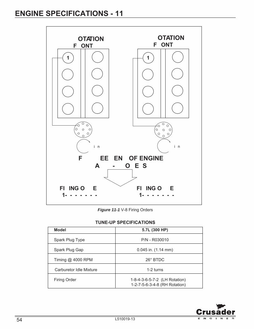
54 L510019-13
ENGINE SPECIFICATIONS - 11
Figure 11-1 V-8 Firing Orders
1
�
�
�
�
�
�
�
1
�
�
�
�
�
�
�
��� ������� �OTATION
F�ONT
��� ������� �OTATION
F�ONT
FI�ING O��E��1-�-�-�-�-�-�-�
FI�ING O��E��1-�-�-�-�-�-�-�
F����EE� EN� OF ENGINEA�� �-� �O�E�S
�����i�n �����i�n
TUNE-UP SPECIFICATIONS Model 5.7L (300 HP)
Spark Plug Type P/N - R030010
Spark Plug Gap 0.045 in. (1.14 mm)
Timing @ 4000 RPM 26° BTDC
Carburetor Idle Mixture 1-2 turns
Firing Order 1-8-4-3-6-5-7-2 (LH Rotation) 1-2-7-5-6-3-4-8 (RH Rotation)

55L510019-13
OUT-OF-SEASON STORAGE - 12NOTICE: The fresh-water cooling system must be serviced before fogging the engine for storage.
WARNING
Operate the bilge blower and be sure no fuel vapors are present when treating the engine. Be sure the engine compartment is well-ventilated to prevent a potential fi re hazard.
5. Remove the fl ame arrestor and start the engine. Operate the engine at a fast idle speed (1000-1500 RPM). Use an aerosol-type fogging solution and spray suffi cient amount, into the carburetor bores, to treat internal surfaces of the engine. Refer to the instructions on the fogging solution canister. Turn the ignition switch to the OFF position.
6. Clean the fl ame arrestor and the vent hoses, and reinstall on the engine. Cover the carburetor ,to prevent the possibility of the water entering the engine through the carburetor, during storage.
7. Close the fuel shut-off valve (if equipped).
ENGINE STORAGE
IMPORTANT: This service should be performed by an Authorized Crusader Premier Dealer.
CAUTION
Refer to FLUSHING COOLING SYSTEM before proceeding.
1. Fill the fuel tanks with gasoline and add a suffi cient amount of gasoline stabilizer, such as STA-BIL™ fuel stabilizer, to prevent the formation of fuel gum and varnish. Follow the instructions on the container.
WARNING
On fuel injected engines, you MUST bleed off fuel pressure before proceeding. Failure to do so may cause personal injury.
WARNING
Operate the bilge blower and be sure no fuel vapors are present when treating the engine. Be sure the engine compartment is well-ventilated to prevent a potential fi re hazard.
2. Remove, empty and clean the fuel fi lter assembly. Reinstall with a new fuel fi lter and gasket/seal. Refer to Engine Maintenance for fi lter replacement procedures.
NOTE: DO NOT re-use old fuel fi lter components. Always replace with new fuel fi lter and gasket/seal.
WARNING
Accumulation of water and other fuel contaminants may form corrosive compounds that can damage the fuel fi lter, and result in fuel leakage. Ethanol blended fuel may increase this risk. For this reason, annual replacement of the fuel fi lter, at a minimum, is required to avoid risk of explosion or fi re.
3. Run the engine and allow it to reach normal operating temperature (a minimum of 10 minutes). Shut down the engine and change the oil and oil fi lter (See ENGINE MAINTENANCE).
4. Flush the cooling system if operating in salt water or brackish water areas. (See ENGINE MAINTENANCE).

56 L510019-13
OUT-OF-SEASON STORAGE - 12
CAUTION
A discharged battery can be damaged by freezing.
IMPORTANT: When removing the drain plugs, insert a wire into the hole to remove any obstruction which would prevent water from draining completely.
FRESH-WATER COOLED MODELS
IMPORTANT: The fresh-water section of the cooling system must be kept fi lled year around with recommended coolant. Make certain that the cooling system is protected with an ethylene glycol antifreeze mixture properly mixed to protect the engine to the lowest temperature that it will be exposed to.
See the ENGINE MAINTENANCE section for testing alkalinity, draining and refi lling procedures of the Fresh Water Cooling System, as required.
IMPORTANT: Drain the sea-water section of the cooling system only.
1. Remove all the drain plugs from the following locations:
• Heat Exchanger - one on outboard side
• Exhaust Elbows - two on each side
• Transmission and Engine Cooler - one drain plug
• Fuel Cooler Canister (Returnless Fuel System Only) - one drain plug
2. Remove the hose from the inlet side of the sea-water pump.
3. Remove the hose from the outlet side of the sea-water pump.
NOTICE: It may be necessary to bend or lift the hoses to allow water to drain completely.
4. Remove the raw water pump impeller. (See ENGINE MAINTENANCE) If inspection proves the impeller to be in good condition, store it in an accessible spot for re-installation at the end of the storage period. A damaged or badly worn impeller should be discarded and a new one installed at the end of the storage period.
NOTE: Removal of the impeller during storage will prevent the impeller vanes from drying and taking a permanent “set”.
5. After the water has completely drained, coat the threads of drain plugs with PerfectSeal (or equivalent), and reinstall in the proper locations. Reinstall the hoses and tighten all the clamps securely.
6. Loosen the engine alternator and raw water pump drive belt(s).
After draining is completed, perform the additional required maintenance as outlined in the MAINTENANCE SCHEDULE under ONCE EACH YEAR.
BATTERY STORAGE
Follow the battery manufacturer’s instructions for storage. If not available, use the following instructions:
• Remove the battery from the boat and clean, removing dirt and grease from the top of the battery.
• Fill the battery with distilled water to the manufacturer’s specifi cations.
• Store the battery in a cool, dry place. Do not store on a concrete surface.
• Periodically (every 30 to 45 days), check the water level and recharge the battery to the manufacturer’s specifi cations. Do not fast charge.
CAUTION
If the boat is to remain in the water during or after draining, close the seacock to prevent a siphoning action that may occur, allowing sea water to fl ow from drain holes or removed hoses.
DRAINING INSTRUCTIONS

57L510019-13
OUT-OF-SEASON STORAGE - 12OUT-OF-SEASON ENGINE WARM-UP
If it is necessary to start your engine(s) during cold weather storage, refer to the following procedure.
1. Refer to “Recommissioning After Storage” to make certain all drain plugs, hoses, batteries and connections are secure.
2. Start the engine(s) and idle until normal engine oil pressure is reached.
3. Raise the engine RPM and hold at 1500 RPM until NORMAL operating temperature is reached.
4. Raise the engine RPM again and hold at 2500 RPM. Allow the engine to run for approximately 5 minutes in order to heat up the exhaust system.
5. Return the engine to idle speed and shut the engine “OFF.”
6. Refer to “Engine Storage” and “Draining Instruction” to make certain the engine is fully protected from freezing during the remaining storage period.
Following this procedure will reduce the possibility of condensation build up in the engine exhaust system, due to cold weather start-ups.
CAUTION
When installing the battery, make certain that you connect the POSITIVE (+) BATTERY CABLE to the POSITIVE (+) BATTERY TERMINAL fi rst, and the NEGATIVE (-) BATTERY CABLE to the NEGATIVE (-) BATTERY TERMINAL last. If the battery cables are reversed, the electrical system will be damaged.
RECOMMISSIONING AFTER STORAGE
IMPORTANT: This service should be performed by an Authorized Crusader Marine Engines Premier Dealer.
When recommissioning the engine after storage, the following items should be checked:
1. Assemble the raw water pump and reinstall on the engine.
2. Check all the cooling system hoses. Be sure they are properly connected and all the hose clamps are tight.
WARNING
Do not use jumper cables and/or a booster battery to start the engine. Do not recharge a weak battery in the boat. Remove the battery and recharge in a ventilated area away from fuel vapors, sparks or open fl ame.
3. Install the fully charged battery. Be sure that all the connections are clean and free from corrosion. Coat the battery terminal connections with an anti-corrosion battery terminal spray.
4. Readjust alternator and water pump drive belt tension.
5. Check engine alignment.
6. Check engine and transmission oil levels.
7. Check engine mount fasteners.
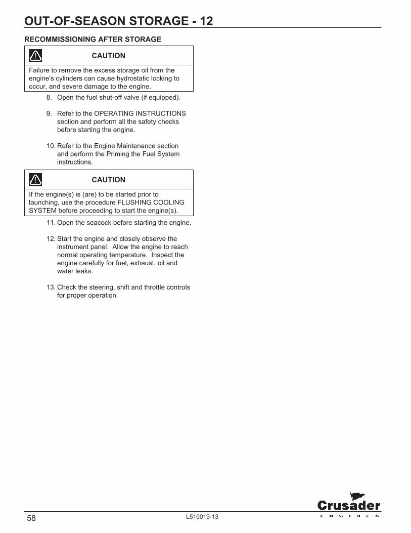
58 L510019-13
OUT-OF-SEASON STORAGE - 12
CAUTION
If the engine(s) is (are) to be started prior to launching, use the procedure FLUSHING COOLING SYSTEM before proceeding to start the engine(s).
11. Open the seacock before starting the engine.
12. Start the engine and closely observe the instrument panel. Allow the engine to reach normal operating temperature. Inspect the engine carefully for fuel, exhaust, oil and water leaks.
13. Check the steering, shift and throttle controls for proper operation.
8. Open the fuel shut-off valve (if equipped).
9. Refer to the OPERATING INSTRUCTIONS section and perform all the safety checks before starting the engine.
10. Refer to the Engine Maintenance section and perform the Priming the Fuel System instructions.
CAUTION
Failure to remove the excess storage oil from the engine’s cylinders can cause hydrostatic locking to occur, and severe damage to the engine.
RECOMMISSIONING AFTER STORAGE

59L510019-13
TROUBLESHOOTING - 13Engine performance complaints usually fall under one of the basic headings listed in the Troubleshooting Guide. When a problem cannot be easily diagnosed, consult a Crusader Marine Engines Premier Dealer for assistance.
Malfunction Possible Cause Corrective Action
Engine will not crank with the Battery switch turned OFF (if Turn the battery switch ON. starter motor, or cranks slowly. equipped)
Remote control not in Neutral Position the remote control exactly position. in Neutral. Blown the ignition fuse or open Replace the fuse - reset circuit circuit breakers. breakers. Loose and/or dirty wiring Check the battery cables and connections. starter circuit wiring. Clean and tighten all connections. Repair or replace the damaged wiring.
Dead Battery Recharge, test and replace as necessary.
Engine Cranks - will not Improper starting procedure. Refer to “STARTING start or is hard starting. ENGINE” in the OPERATING INSTRUCTIONS section.
No fuel - empty fuel tank Check the fuel tank level - fi ll tank(s). Open shut-off valve(s). Plugged fuel fi lters. No fuel to the carburetor Plugged or kinked fuel lines or plugged fuel-tank vent. Faulty fuel pump - check electrical connections. Faulty anti-siphon valve. Choke operating improperly Check choke linkage for freedom of movement and proper adjustment.
Check 12V power lead.
Engine fl ooded Open the throttle 100% and crank the engine. When the engine starts, immediately return the throttle to 1000 RPM.
Ignition system malfunction Service ignition system. Check tune-up specifi cations.
Contaminated fuel Check fuel for water or other contamination. If contaminated, drain and clean the fuel system.
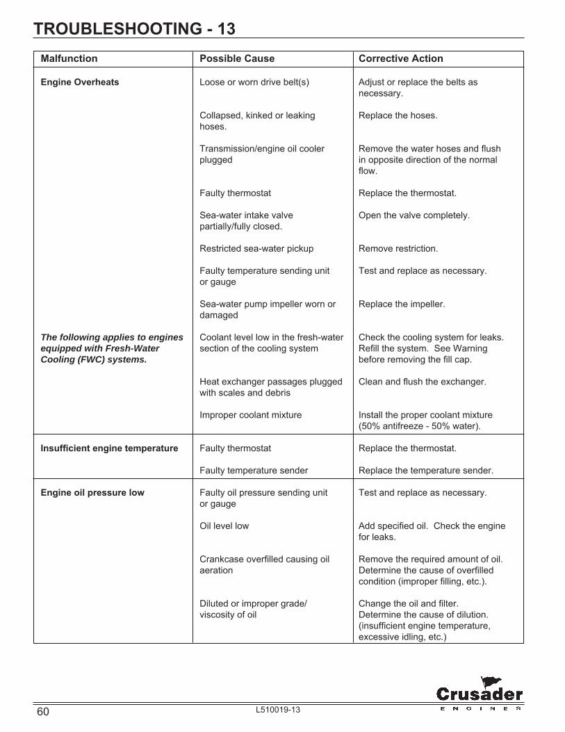
60 L510019-13
TROUBLESHOOTING - 13 Malfunction Possible Cause Corrective Action
Engine Overheats Loose or worn drive belt(s) Adjust or replace the belts as necessary.
Collapsed, kinked or leaking Replace the hoses. hoses.
Transmission/engine oil cooler Remove the water hoses and fl ush plugged in opposite direction of the normal fl ow.
Faulty thermostat Replace the thermostat. Sea-water intake valve Open the valve completely. partially/fully closed. Restricted sea-water pickup Remove restriction. Faulty temperature sending unit Test and replace as necessary. or gauge
Sea-water pump impeller worn or Replace the impeller. damaged
The following applies to engines Coolant level low in the fresh-water Check the cooling system for leaks. equipped with Fresh-Water section of the cooling system Refi ll the system. See Warning Cooling (FWC) systems. before removing the fi ll cap.
Heat exchanger passages plugged Clean and fl ush the exchanger. with scales and debris
Improper coolant mixture Install the proper coolant mixture (50% antifreeze - 50% water).
Insuffi cient engine temperature Faulty thermostat Replace the thermostat. Faulty temperature sender Replace the temperature sender.
Engine oil pressure low Faulty oil pressure sending unit Test and replace as necessary. or gauge
Oil level low Add specifi ed oil. Check the engine for leaks. Crankcase overfi lled causing oil Remove the required amount of oil. aeration Determine the cause of overfi lled condition (improper fi lling, etc.). Diluted or improper grade/ Change the oil and fi lter. viscosity of oil Determine the cause of dilution. (insuffi cient engine temperature, excessive idling, etc.)
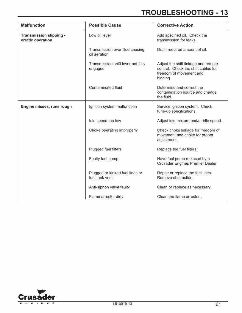
61L510019-13
TROUBLESHOOTING - 13 Malfunction Possible Cause Corrective Action
Transmission slipping - Low oil level Add specifi ed oil. Check the erratic operation transmission for leaks.
Transmission overfi lled causing Drain required amount of oil. oil aeration
Transmission shift lever not fully Adjust the shift linkage and remote engaged control. Check the shift cables for freedom of movement and binding.
Contaminated fl uid Determine and correct the contamination source and change the fl uid. Engine misses, runs rough Ignition system malfunction Service ignition system. Check tune-up specifi cations.
Idle speed too low Adjust idle mixture and/or idle speed.
Choke operating improperly Check choke linkage for freedom of movement and choke for proper adjustment. Plugged fuel fi lters Replace the fuel fi lters. Faulty fuel pump. Have fuel pump replaced by a Crusader Engines Premier Dealer
Plugged or kinked fuel lines or Repair or replace the fuel lines. fuel tank vent Remove obstruction.
Anti-siphon valve faulty Clean or replace as necessary. Flame arrestor dirty Clean the fl ame arrestor..
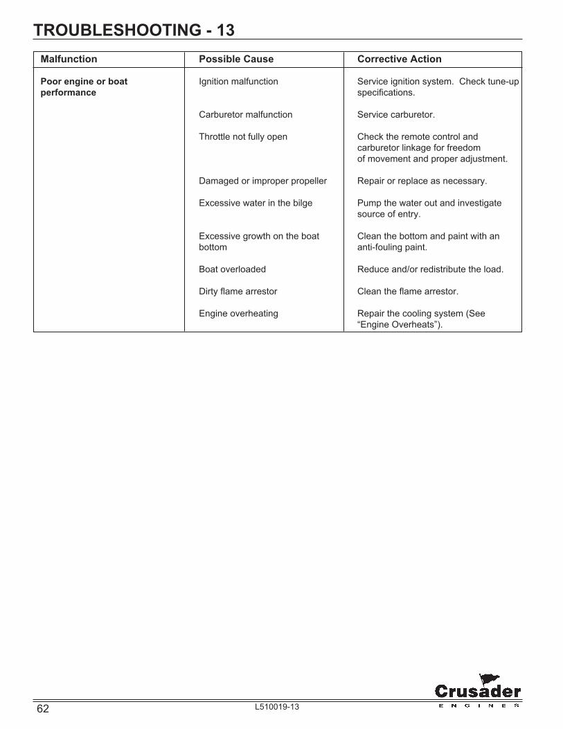
62 L510019-13
TROUBLESHOOTING - 13 Malfunction Possible Cause Corrective Action
Poor engine or boat Ignition malfunction Service ignition system. Check tune-up performance specifi cations.
Carburetor malfunction Service carburetor.
Throttle not fully open Check the remote control and carburetor linkage for freedom of movement and proper adjustment.
Damaged or improper propeller Repair or replace as necessary. Excessive water in the bilge Pump the water out and investigate source of entry. Excessive growth on the boat Clean the bottom and paint with an bottom anti-fouling paint. Boat overloaded Reduce and/or redistribute the load. Dirty fl ame arrestor Clean the fl ame arrestor. Engine overheating Repair the cooling system (See “Engine Overheats”).
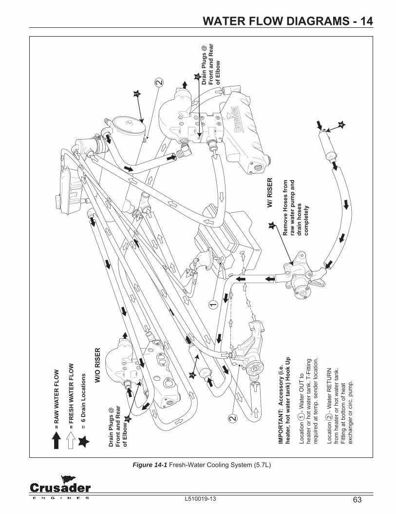
63L510019-13
W/ R
ISER
W/O
RIS
ER
= R
AWW
ATER
FLO
W
= FR
ESH
WAT
ER F
LOW
1
2
IMPO
RTA
NT:
Acc
esso
ry (i
.e.
heat
er, h
ot w
ater
tank
) Hoo
k U
p
Loca
tion
1 -
Wat
er O
UT
to
heat
er o
r hot
wat
er ta
nk. T
-Fitt
ing
requ
ired
at te
mp.
sen
der l
ocat
ion.
Loca
tion
2 -
Wat
er R
ETU
RN
fro
m h
eate
r or h
ot w
ater
tank
. Fi
tting
at b
otto
m o
f hea
t ex
chan
ger o
r circ
. pum
p.
1
Rem
ove
Hos
es fr
om
raw
wat
er p
ump
and
drai
n ho
ses
com
plet
ely
4
3
2
= 6
Dra
in L
ocat
ions
5
6
Dra
in P
lugs
@Fr
ont a
nd R
ear
of E
lbow
Dra
in P
lugs
@Fr
ont a
nd R
ear
of E
lbow
2
Figure 14-1 Fresh-Water Cooling System (5.7L)
WATER FLOW DIAGRAMS - 14

64 L510019-13
ENGINE HARNESS WIRING DIAGRAMS - 15
CIRCUIT CIRCUIT ENGINE HARNESS NUMBER NAME WIRE COLOR
1. GROUND BLACK 2. TACHOMETER GRAY 3. WATER TEMPERATURE TAN 4. N/C 5. IGNITION PURPLE 6. BATTERY RED 7. STARTER YELLOW/RED 8. OIL PRESSURE LT. BLUE 9. N/C 10. N/C
NOTE: ENGINE HARNESS WIRED FOR PANELS USING VOLTMETERS ONLY.
NOTE A : POWER FOR A FUSED ACCESSORY PANEL MAY BE TAKEN FROM THIS LOCATION. LOAD CANNOT EXCEED 30 AMPS.
WIRE HARNESS COLOR CHART
10
43
2
ENGINEHARNESSADAPTER
5 6
7
9
81
A
IMPORTANT: Your engine is designed to work with the standard electronics installed in your boat. If you add other electrical components or accessories, you could change the way the fuel injection controls your engine or the overall electrical system functions. Before adding electrical equipment, consult your dealer. If you don’t, your engine may not perform properly.
CAUTION
Add-on equipment may adversely affect the alternator output or overload the electrical system. Any damage caused as a result will not be covered by, and may void, your warranty.

65L510019-13
ENGINE HARNESS WIRING DIAGRAMS - 15
GRD
SEN
EXC
BAT
BLACK 6 ga
PURPLE/WHITE 16 ga
RED
10-P INE NG INE
HAR NE S S
S T AR T E R
BAT
S
I
ALT E R NAT OR
WAT E RT E MPS E NS OR
3
WaterT emp
TAN 14ga
6 ga
60AC ircuitB reaker
RED/WHITE
RED
6B attery
10ga 125 C
RE
D -
6 g
a
RED - 6 ga
YELLOW 12 ga
OILP R E S S UR ES E NS OR
T R ANS MIS S IONNE UT R ALS AF E T YS WIT C H
LT. BLUE 14ga8
OilP ressure
7S tarter
YEL/REDYEL/RED12 ga
DIS T R IB UT OR(MALLOR Y )
- +IG NIT IONC OIL
B allastR es istor
2
T achometer
GREEN
GRAY
RED 16 ga
16ga
14ga
RED
BROWN PURPLE/WHITE
T o - E XCA lternator
5Ignition
- +C AR B UR E T OR
E LE C T R ICC HOK E
MODULE
PPL/WHT 14 ga
Oil P ressureF uel P umpInterlockS witch
NO
NCC
RED 14 ga
RED 14 ga
RE
D 1
4 g
a
RED - 14ga
+ -E LE C T R IC
F UE LP UMP
BLACK 14 ga BLACK 10ga1
G round
T o - C arburetorC hoke
GROUNDENGINE BLOCK
LowOil P ressureS witch
WaterT emperatureS witch
E NG INE WAR NING C IR C UIT
LT. Green 14ga
Not Used
S tarterR elay
3086
85 87A87
FROM PIN 5
RED/WHITE 16 ga
RED
/WH
ITE 1
2 ga
12 ga
BLACK 12 ga
FROM PIN 1
P UR P LE /WHIT E 16 ga
PU
RP
LE
/WH
ITE
14
ga
DKGRN/YEL
14 ga
T o - S tarterR elay
BLACK 14 gaFROM PIN 1
12 in. long
125 C
Pigtail connectornear 10-Pin connector
B AT T E R Y
+-
100A
LIT T LE
F US E
5A F use
Figure 15-3 Typical Engine Wiring w/Mallory Ignition

66 L510019-13
LITERATURE - 16To obtain service and/or parts literature for your Crusader Marine Engines, contact the following:
IMPORTANT: When contacting the factory for service information, be sure to include your engine model and serial number to insure the service information you receive is correct.
Crusader Marine EnginesPublications Department
P.O. Drawer 369Little Mountain, SC 29075
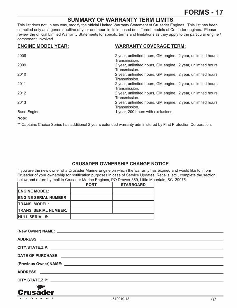
67L510019-13
SUMMARY OF WARRANTY TERM LIMITSThis list does not, in any way, modify the offi cial Limited Warranty Statement of Crusader Engines. This list has been compiled only as a general outline of year and hour limits imposed on different models of Crusader engines. Please review the offi cial Limited Warranty Statements for specifi c terms and limitations as they apply to the particular engine / component involved.
ENGINE MODEL YEAR: WARRANTY COVERAGE TERM:
2008 2 year, unlimited hours, GM engine. 2 year, unlimited hours, Transmission.
2009 2 year, unlimited hours, GM engine. 2 year, unlimited hours, Transmission.
2010 2 year, unlimited hours, GM engine. 2 year, unlimited hours, Transmission.
2011 2 year, unlimited hours, GM engine. 2 year, unlimited hours, Transmission.
2012 2 year, unlimited hours, GM engine. 2 year, unlimited hours, Transmission.
2013 2 year, unlimited hours, GM engine. 2 year, unlimited hours, Transmission.
Base Engine 1 year, 200 hours with exclusions.Note:** Captains Choice Series has additional 2 years extended warranty administered by First Protection Corporation.
CRUSADER OWNERSHIP CHANGE NOTICEIf you are the new owner of a Crusader Marine Engine on which the warranty has expired and would like to inform Crusader of your ownership for notifi cation purposes in case of Service Updates, Recalls, etc., complete the section below and return by mail to Crusader Marine Engines, PO Drawer 369, Little Mountain, SC 29075.
(New Owner) NAME:
ADDRESS:
CITY,STATE,ZIP:
DATE OF PURCHASE:
(Previous Owner)NAME:
ADDRESS:
CITY,STATE,ZIP:
PORT STARBOARDENGINE MODEL:ENGINE SERIAL NUMBER:TRANS. MODEL:TRANS. SERIAL NUMBER:HULL SERIAL #:
FORMS - 17


69L510019-13
CRUSADER WARRANTY TRANSFER APPLICATION (PORT OR SINGLE ENGINE)
The remainder of the original Crusader limited warranty is transferable within thirty (30) days of date of sale by the original owner/user to a subsequent purchaser for the remainder of the unused portion of the original warranty term, provided the engine(s) operating hours do not exceed 300. The original date of sale or original in-service date (whichever comes fi rst) begins the warranty coverage period.Direct Sale by Owner/Dealer or First Operator: • The second purchaser can be registered as the owner and retain the unused portion of the warranty term by sending the following: - Original owner’s Warranty Registration Card - Copy of Bill of Sale/Sales Contract/Operator Contract - Completed Warranty Transfer Application - Warranty transfer feeTransfer Fee: • The fee for transfer is $50.00 per engine. The applicable transfer fee must be submitted via certifi ed check within 30 days of date of sale
along with the transfer application information to: Crusader Marine Engines Marine Warranty Transfer P.O. Drawer 369 Little Mountain, S.C., 29075, USA • A new ”Owner Warranty Registration Card” will be issued with the new owner’s name and address. Registration records will be
changed in the factory registration fi le.OUTSIDE THE U.S. AND CANADA, CONTACT YOUR LOCAL CRUSADER DEALER OR WARRANTY SERVICES AT (803)345-0050 FOR MORE INFORMATION ON HOW TO APPLY TO THIS PROGRAM.IMPORTANT! PURCHASER NOTICE: The checks listed below are designed to insure safety and satisfaction. Premier Crusader Dealer Technicians have received step-by-step instruction in the performance of the Pre-Delivery Inspection. Therefore, we require the following inspection be performed at your expense by a qualifi ed technician prior to delivery. By signature the technician certifi es that he/she has checked the installation and operation of the engine and fi nds it to be performing properly. All terms in the Limited Warranty located in the Engine Owners Manual still apply.
ENGINE MODEL: ENGINE SERIAL: TRANS. SERIAL: ENGINE HOURS: HULL SERIAL #:
DATE OF SALE (2ND Owner) / / DATE OF SALE (1st Owner/1st Operator) / /
(New Owner) (Previous Owner)NAME: NAME:
ADDRESS: ADDRESS:
CITY,STATE, ZIP CITY,STATE, ZIP
I hereby certify the Pre-Delivery Checklist on engine # and have corrected any abnormality revealed by this inspection.
(Technician Signature, Dealer & Date) (Seller’s Signature & Date) (Purchaser’s Signature & Date)
Type Information
To Prevent
Processing Delay
Pre-Delivery Checklist - PORT or SingleCheck for Bulletins
Engine Oil: Check
Drive Lube: Check All Fuel Lines: Confi rm No Leaks
All Water Lines: Confi rm No Leaks
Battery Rating, Charge, and Level: Check
Control Adjustments:Confi rm Proper Operation
All Drain Plugs: Confi rm Proper Installation
Belt and Pulley: Inspect for Damage
Gauges: Check for Proper Operation
Record Propeller Size, Rotation and WOTWOT RPM_______Diameter________ Pitch________Rotation_________
Record Fuel Pressure, WOT ______ Trouble Codes CheckedTrouble Codes Cleared
Dealer Reviewed Warranty with Owner
Electrical Wiring: Check for Proper Installation
All Oil Lines: Confi rm No Leaks
FORMS - 17

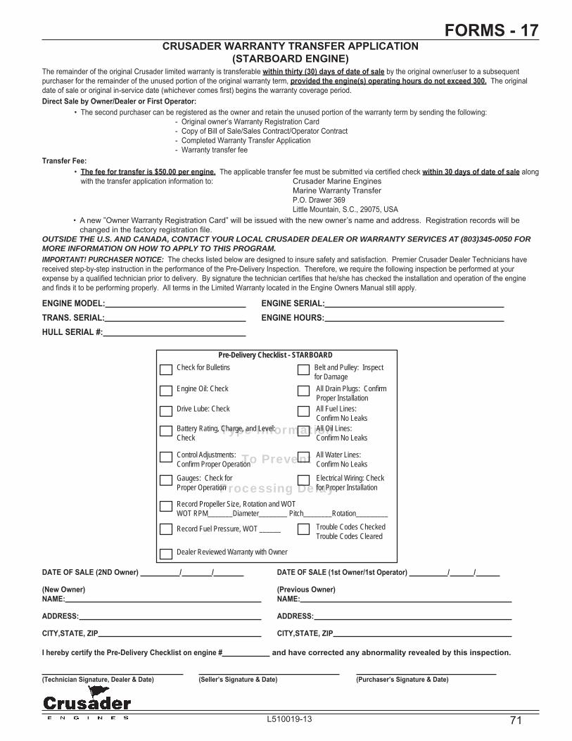
71L510019-13
CRUSADER WARRANTY TRANSFER APPLICATION(STARBOARD ENGINE)
The remainder of the original Crusader limited warranty is transferable within thirty (30) days of date of sale by the original owner/user to a subsequent purchaser for the remainder of the unused portion of the original warranty term, provided the engine(s) operating hours do not exceed 300. The original date of sale or original in-service date (whichever comes fi rst) begins the warranty coverage period.Direct Sale by Owner/Dealer or First Operator: • The second purchaser can be registered as the owner and retain the unused portion of the warranty term by sending the following: - Original owner’s Warranty Registration Card - Copy of Bill of Sale/Sales Contract/Operator Contract - Completed Warranty Transfer Application - Warranty transfer feeTransfer Fee: • The fee for transfer is $50.00 per engine. The applicable transfer fee must be submitted via certifi ed check within 30 days of date of sale along
with the transfer application information to: Crusader Marine Engines Marine Warranty Transfer P.O. Drawer 369 Little Mountain, S.C., 29075, USA • A new ”Owner Warranty Registration Card” will be issued with the new owner’s name and address. Registration records will be
changed in the factory registration fi le.OUTSIDE THE U.S. AND CANADA, CONTACT YOUR LOCAL CRUSADER DEALER OR WARRANTY SERVICES AT (803)345-0050 FOR MORE INFORMATION ON HOW TO APPLY TO THIS PROGRAM.IMPORTANT! PURCHASER NOTICE: The checks listed below are designed to insure safety and satisfaction. Premier Crusader Dealer Technicians have received step-by-step instruction in the performance of the Pre-Delivery Inspection. Therefore, we require the following inspection be performed at your expense by a qualifi ed technician prior to delivery. By signature the technician certifi es that he/she has checked the installation and operation of the engine and fi nds it to be performing properly. All terms in the Limited Warranty located in the Engine Owners Manual still apply.
ENGINE MODEL: ENGINE SERIAL: TRANS. SERIAL: ENGINE HOURS: HULL SERIAL #:
Type Information
To Prevent
Processing Delay
Pre-Delivery Checklist - STARBOARDCheck for Bulletins
Engine Oil: Check
Drive Lube: Check All Fuel Lines: Confi rm No Leaks
All Water Lines: Confi rm No Leaks
Battery Rating, Charge, and Level: Check
Control Adjustments:Confi rm Proper Operation
All Drain Plugs: Confi rm Proper Installation
Belt and Pulley: Inspect for Damage
Gauges: Check for Proper Operation
Record Propeller Size, Rotation and WOTWOT RPM_______Diameter________ Pitch________Rotation_________
Record Fuel Pressure, WOT ______ Trouble Codes CheckedTrouble Codes Cleared
Dealer Reviewed Warranty with Owner
Electrical Wiring: Check for Proper Installation
All Oil Lines: Confi rm No Leaks
DATE OF SALE (2ND Owner) / / DATE OF SALE (1st Owner/1st Operator) / /
(New Owner) (Previous Owner)NAME: NAME:
ADDRESS: ADDRESS:
CITY,STATE, ZIP CITY,STATE, ZIP
I hereby certify the Pre-Delivery Checklist on engine # and have corrected any abnormality revealed by this inspection.
(Technician Signature, Dealer & Date) (Seller’s Signature & Date) (Purchaser’s Signature & Date)
FORMS - 17


73L510019-13
NOTES - 18