design and analysis of a four wheeled planetary roverc3p0.ou.edu/irl/theses/roman-ms.pdf · design...
TRANSCRIPT
UNIVERSITY OF OKLAHOMA
GRADUATE COLLEGE
Design and Analysis
of a
Four Wheeled Planetary Rover
A Thesis
SUBMITTED TO THE GRADUATE FACULTY
in partial fulfillment of the requirements for the
degree of
MASTER OF SCIENCE
By
Matthew J. Roman
Norman, Oklahoma
2005
Design and Analysis
of a
Four Wheeled Planetary Rover
A THESIS APPROVED FOR THE
SCHOOL OF AEROSPACE & MECHANICAL ENGINEERING
By
Prof. David P. Miller
Prof. Kuang-Hua Chang
Prof. Dean Hougen

c© by Matthew J. Roman 2005
All Rights Reserved.
Acknowledgements
I would like to thank David Miller and the remaining faculty in the college of engi-
neering for their helpful advice. They have directed the path I’m on toward a future
that I dream of. Thanks to Malin Space Science Systems for providing the funds
for this project. Thank you to all of my friends who have made sure that I learn
from life outside the lab as well. Most importantly thanks to my family and their
never-ending support. I could not have gone so far without such loving parents,
Thank you Mom and Dad.
iv
Contents
Acknowledgements iv
List Of Tables viii
List Of Figures ix
Abstract xi
1 Introduction 1
1.1 Rovers for Exploration . . . . . . . . . . . . . . . . . . . . . . . . . . 2
1.2 Rover Suspension Systems . . . . . . . . . . . . . . . . . . . . . . . . 4
1.2.1 Independant Spring Suspension . . . . . . . . . . . . . . . . . 5
1.2.2 Articulated Body Suspension . . . . . . . . . . . . . . . . . . 7
1.2.3 Rocker-Bogie Suspension . . . . . . . . . . . . . . . . . . . . . 10
1.2.4 Four Wheel Suspensions . . . . . . . . . . . . . . . . . . . . . 17
1.2.5 Legged Suspension . . . . . . . . . . . . . . . . . . . . . . . . 18
1.3 Design Goals for Mars Rovers . . . . . . . . . . . . . . . . . . . . . . 25
1.4 Terrain and Environment . . . . . . . . . . . . . . . . . . . . . . . . . 26
1.5 Four vs. Six wheels . . . . . . . . . . . . . . . . . . . . . . . . . . . . 29
1.5.1 Are six wheels overkill? . . . . . . . . . . . . . . . . . . . . . . 29
1.5.2 Why 4 wheels? . . . . . . . . . . . . . . . . . . . . . . . . . . 32
1.6 Organization of Thesis . . . . . . . . . . . . . . . . . . . . . . . . . . 34
2 Solar Rover-II Mechanical System 36
2.1 SR-II design goals . . . . . . . . . . . . . . . . . . . . . . . . . . . . . 37
2.2 Main Body . . . . . . . . . . . . . . . . . . . . . . . . . . . . . . . . 38
v
2.3 Drive Train . . . . . . . . . . . . . . . . . . . . . . . . . . . . . . . . 44
2.3.1 Wheel torque . . . . . . . . . . . . . . . . . . . . . . . . . . . 45
2.3.2 Mobility Power Requirements . . . . . . . . . . . . . . . . . . 47
2.3.3 Motors . . . . . . . . . . . . . . . . . . . . . . . . . . . . . . . 49
2.3.4 Drive Train Concepts . . . . . . . . . . . . . . . . . . . . . . . 53
2.3.5 Motor Selection . . . . . . . . . . . . . . . . . . . . . . . . . . 57
2.3.6 Power Transfer . . . . . . . . . . . . . . . . . . . . . . . . . . 60
2.4 Suspension . . . . . . . . . . . . . . . . . . . . . . . . . . . . . . . . . 64
2.4.1 Central Differential . . . . . . . . . . . . . . . . . . . . . . . . 64
2.4.2 Structure . . . . . . . . . . . . . . . . . . . . . . . . . . . . . 67
2.5 Wheels . . . . . . . . . . . . . . . . . . . . . . . . . . . . . . . . . . . 72
2.6 Electronics . . . . . . . . . . . . . . . . . . . . . . . . . . . . . . . . . 73
2.6.1 Sensors . . . . . . . . . . . . . . . . . . . . . . . . . . . . . . . 74
2.6.1.1 Obstacle Avoidance . . . . . . . . . . . . . . . . . . 74
2.6.1.2 Tilt,Roll, and Heading . . . . . . . . . . . . . . . . . 75
2.6.1.3 Odometry . . . . . . . . . . . . . . . . . . . . . . . . 75
2.6.2 Power . . . . . . . . . . . . . . . . . . . . . . . . . . . . . . . 76
2.6.2.1 Solar Panel . . . . . . . . . . . . . . . . . . . . . . . 76
2.6.2.2 Batteries . . . . . . . . . . . . . . . . . . . . . . . . 76
2.7 Control System . . . . . . . . . . . . . . . . . . . . . . . . . . . . . . 77
2.8 Construction . . . . . . . . . . . . . . . . . . . . . . . . . . . . . . . 78
3 Experimental Setup and Procedure 79
3.1 Rover Field Test . . . . . . . . . . . . . . . . . . . . . . . . . . . . . 80
3.1.1 Location and Terrain features . . . . . . . . . . . . . . . . . . 81
3.1.2 Rover Setup . . . . . . . . . . . . . . . . . . . . . . . . . . . . 81
3.1.3 Experiment Results . . . . . . . . . . . . . . . . . . . . . . . . 83
3.2 Rover Laboratory Experiment . . . . . . . . . . . . . . . . . . . . . . 87
3.2.1 Obstacle Traversing . . . . . . . . . . . . . . . . . . . . . . . . 88
3.2.2 Slope . . . . . . . . . . . . . . . . . . . . . . . . . . . . . . . . 90
3.2.3 Driving Power . . . . . . . . . . . . . . . . . . . . . . . . . . . 91
4 Results and Lessons Learned 93
vi
Reference List 96
Appendix A
Data Calculations . . . . . . . . . . . . . . . . . . . . . . . . . . . . . . . . 103
Appendix B
Mechanical Drawings . . . . . . . . . . . . . . . . . . . . . . . . . . . . . . 117
vii
List Of Tables
3.1 SR-II power used while maneuvering over various surfaces . . . . . . 91
viii
List Of Figures
1.1 Lunokhod, Russian for ”Moon Walker” (image reproduced from NASA) 4
1.2 Blue Rover and Robby are articulated body rovers designed by NASA(image
reproduced from NASA) . . . . . . . . . . . . . . . . . . . . . . . . . 7
1.3 Russian built Marsokhod (image reproduced from NASA) . . . . . . . 8
1.4 NASA’s Pathfinder rover on the 1997 mission and one of the twin
Mars Exploration Rovers in 2004 (images reproduced from NASA) . . 10
1.5 Link style mobility systems (images reproduced from NASA) . . . . . 12
1.6 Rocky Rover series (images reproduced from NASA) . . . . . . . . . . 14
1.7 Changing direction . . . . . . . . . . . . . . . . . . . . . . . . . . . . 16
1.8 Sandia National Labs’ Ratler rover and Nomad rover (images repro-
duced from [45] and NASA) . . . . . . . . . . . . . . . . . . . . . . . 18
1.9 Ambler, a walking rover with a circulating gait and Dante, a frame
walking rover (image reproduced from [8, 6]) . . . . . . . . . . . . . . 19
1.10 Genghis and Attila biologically inspired hexapod robots (image repro-
duced from MIT AI lab) . . . . . . . . . . . . . . . . . . . . . . . . . 22
1.11 Rhex simplified leg design for a walking robot (image reproduced from
[36]) . . . . . . . . . . . . . . . . . . . . . . . . . . . . . . . . . . . . 23
1.12 Qrio, a humanoid robot and Yambo-III a simplified biped robot (image
reproduced from Sony corp. and [41]) . . . . . . . . . . . . . . . . . . 24
1.13 Viking 2 landing site (image reproduced from NASA) . . . . . . . . . 27
1.14 Pathfinder landing site (image reproduced from NASA) . . . . . . . . 28
1.15 MER Opportunity landing site (image reproduced from NASA) . . . . 28
1.16 Sojourner climbing rocks (image reproduced from NASA) . . . . . . . 30
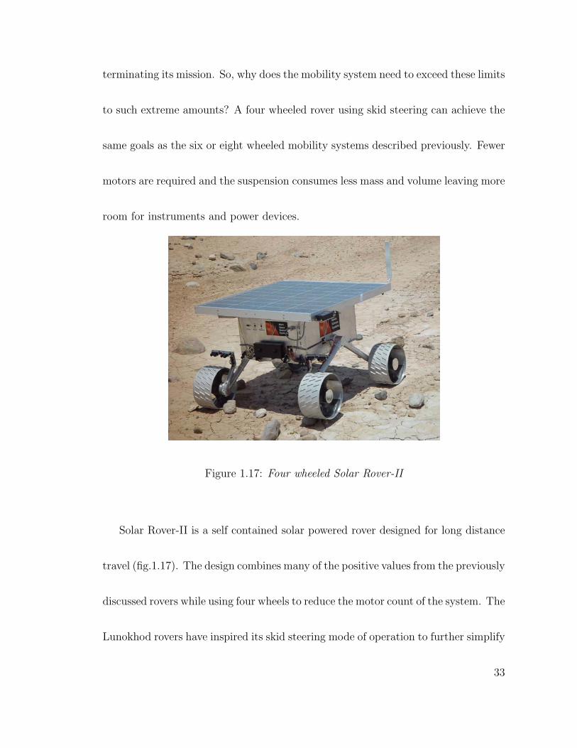
1.17 Four wheeled Solar Rover-II . . . . . . . . . . . . . . . . . . . . . . . 33
ix
2.1 Solar Rover-II body and solar panel . . . . . . . . . . . . . . . . . . . 40
2.2 Honeycomb constructed body with the reinforced plate to which the
geared differential housing is mounted . . . . . . . . . . . . . . . . . . 42
2.3 wheel torque free body diagram . . . . . . . . . . . . . . . . . . . . . . 46
2.4 SR-II with motors in place . . . . . . . . . . . . . . . . . . . . . . . . 52
2.5 Belt drive with tensioning pulleys . . . . . . . . . . . . . . . . . . . . 53
2.6 Chain and Sprocket drive with idler sprockets . . . . . . . . . . . . . . 54
2.7 Drive train concepts using bevel gears and drive shafts . . . . . . . . . 57
2.8 Dual output bevel gear set and planetary drive . . . . . . . . . . . . . 60
2.9 Lower bevel gear set and wheel axle . . . . . . . . . . . . . . . . . . . 62
2.10 Cross section of SR-II’s hollow wheel axle . . . . . . . . . . . . . . . . 63
2.11 Central gear differential mounted to the center of the body . . . . . . . 66
2.12 Tubular suspension structure . . . . . . . . . . . . . . . . . . . . . . . 67
2.13 Central differential and motor mounting inside the body . . . . . . . . 68
2.14 Upper gear box housing . . . . . . . . . . . . . . . . . . . . . . . . . . 69
2.15 Lower gear box housing (front) . . . . . . . . . . . . . . . . . . . . . . 71
2.16 Lower gear box housing (back) . . . . . . . . . . . . . . . . . . . . . . 71
2.17 Sharp infrared range finding sensor . . . . . . . . . . . . . . . . . . . 74
3.1 SR-II near the Salton Sea during the field test . . . . . . . . . . . . . 80
3.2 SR-II thermal delamination of the wheel . . . . . . . . . . . . . . . . 85
3.3 SR-II position data taken during the field test . . . . . . . . . . . . . 86
3.4 Laboratory rover setup . . . . . . . . . . . . . . . . . . . . . . . . . . 87
3.5 SR-II climbing over a bump obstacle . . . . . . . . . . . . . . . . . . 88
3.6 SR-II climbing over a step obstacle . . . . . . . . . . . . . . . . . . . 89
3.7 SR-II climbing a wooden plank slope . . . . . . . . . . . . . . . . . . . 90
3.8 SR-II outdoor slope test . . . . . . . . . . . . . . . . . . . . . . . . . 91
x
Abstract
Rovers are important for conducting in-situ scientific analysis of objectives that
are separated by many meters to tens of kilometers. Current mobility designs are
complex, using many wheels or legs. They are open to mechanical failure caused by
the harsh environment on Mars. This thesis describes Solar Rover-II, a four wheeled
rover capable of traversing rough terrain using an efficient high degree of mobility
suspension system. The primary mechanical feature of the SR-II design is its drive
train simplicity, which is accomplished by using only two motors for mobility. Both
motors are located inside the body where thermal variation is kept to a minimum,
increasing reliability and efficiency. Four wheels are used because there are few
obstacles on natural terrain that require both front wheels of the rover to climb
simultaneously. A series of mobility experiments in the Southern California desert
concluded that SR-II can achieve greater than 1km traverses in Mars like terrain
during the six hours of peak solar energy per day.
xi
Chapter 1
Introduction
Mobile robotic vehicles can be sent to an unknown surface and withstand the deadly
environment of space with a much lower price tag and expenditure than a manned
mission. The Russians landed two robotic vehicles on the moon and two more on
Mars during the 1970’s, another three from NASA have landed on Mars since then.
The rovers, Lunokhod 1 and 2 were able to explore regions further from the landing
site and spend more time on the moon than a manned mission could have during that
time. The two Russian Mars missions failed before achieving any science goals. In
1997 the Mars Pathfinder mission landed a small rover named Sojourner to explore
the surface of the red planet. Two more rovers, Spirit and Opportunity, landed on
opposite sides of Mars in January 2004 during the Mars Exploration Rover mission
(MER). The Pathfinder and MER missions cost approximately $265 and $820 million
1
respectively, which is much cheaper than the $80 billion to $1 trillion estimates for
landing a man on Mars. The rovers have the capability to conduct many science
experiments in the area that they landed. Sojourner surveyed the area within about
10m radius around its lander, larger than the 3m reach of the arm on one side of the
Mars Viking Landers. The MER rovers explored more than 5km away from their
landers, which is equivalent to the average distance the lunar rover was driven away
from the landing module during the Apollo program. These robotic missions have
verified that remote science can be accomplished on the surface of another planet
with a high degree of success. They allow access to areas of interest on the surface
instead of being confined to the local area around the lander.
1.1 Rovers for Exploration
The idea of sending a rover to the surface of another planet is to allow earth bound
scientist’s access to specific areas of interest without enduring the harsh environ-
ments of space [50]. The rover carries instruments to various terrestrial formations
2
for in-situ experimentation. The goal of the rover is to move between areas of inter-
est quickly and safely. In order to better represent the planet of interest the rover
must be able to travel tens of kilometers.
Rovers designed for the exploration of other planets have had very complex mo-
bility systems using large numbers of wheels or legs and sometimes multiple bodies.
Two specific types of rovers have been to the surface of another planet: the Lunokhod
rovers using an eight wheel design and three Mars rovers using the six wheel rocker
bogie suspension. While the large number of wheels increases the stability over
uneven terrain, it also increases complexity in the design. Present day Mars rover
suspension systems use six wheels but require more than eight motors to drive them.
Future rovers are also being designed which use many wheels. New technology is
being added to the rovers so that when the drive train does fail the rover will remain
mobile, though with reduced capabilities.
The purpose of this thesis is to design and build a mobile robot for long dis-
tance travel across terrain analogous to the surface of Mars. The primary focus of
the design will be to maintain a high degree of mobility over rough terrain, while
simplifying the drive-train and suspension. It is important to simplify the drive
3
mechanisms to increase reliability during operation and lengthen the life span of the
rover. Fewer component interfaces and moving parts can increase efficiency as well.
1.2 Rover Suspension Systems
The major types of mobility systems are discussed below to identify their positive
and negative attributes. Each of the rovers was designed with the intent to conduct
science on an unstructured foreign surface. The ability of each system to traverse
obstacles and its mechanism for steering are two major elements that define each
rover.
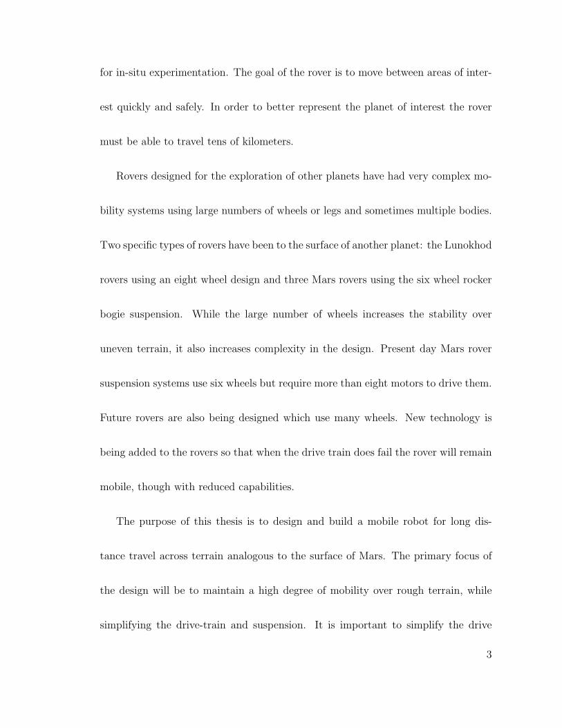
Figure 1.1: Lunokhod, Russian for ”Moon Walker” (image reproduced from NASA)
4
1.2.1 Independant Spring Suspension
The first two rovers driven across the surface of another planet were the Russian
made Lunokhods (fig.1.1). These twin rovers landed on the Moon in 1970 on Luna
17 and again in 1973 on Luna 21 capturing thousands of images and conducting
hundreds of scientific experiments during their mission [38]. Together the rovers
lasted 414 days and covered 50km across the lunar surface. The rovers used a
single tub style chassis with a convex lid to house all of the electronics, TV cameras,
batteries, and navigation sensors. Lunokhod 2 was 840kg, 84kg more than Lunokhod
1 because it carried another camera with adjustable image rates [39]. The tub was
pressurized to one atmosphere and kept within 0 − 40Co to isolate the internal
components from the damaging effects of the vacuum of space [27, 13]. This is
important because the electronic hardware did not have to be specifically designed
for a space application, saving time and money. The top of the tub and inside of
the lid were covered with solar arrays, the lid would open to allow the batteries to
charge after a lunar night. Radio isotope heaters were used to keep the batteries
warm which kept the rover alive during the very cold and long lunar night.
5
The Lunokhods were the size of a compact car with a wheel base of 1.7m and
a track of 1.6m. The eight wheel suspension was designed to allow the vehicle
to traverse obstacles 40cm high. The 51cm diameter wheels were independently
powered with a multi-speed motor, two forward speeds at 1kmhr
and 2kmhr
and a single
reverse speed [23]. The wheel assemblies included a brake to stop the rover from
rolling down steep slopes and a separation device that could permanently free the
wheel if the motor ceased. The wheels were similar to a spoke bicycle wheel with a
wire mesh tire and titanium treads. In order to reduce the complexity of the drive
train the rover used differential or “skid” steering to change direction. The left and
right sets of wheels were powered at different speeds to get the rover to spin about
an axis perpendicular to the horizontal plane. Steering movements were kept to a
minimum to reduce the chance of piling lunar soil in the wheels causing the rover to
get stuck.
6
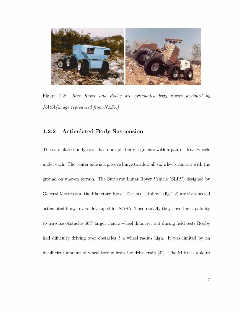
Figure 1.2: Blue Rover and Robby are articulated body rovers designed by
NASA(image reproduced from NASA)
1.2.2 Articulated Body Suspension
The articulated body rover has multiple body segments with a pair of drive wheels
under each. The center axle is a passive hinge to allow all six wheels contact with the
ground on uneven terrain. The Surveyor Lunar Rover Vehicle (SLRV) designed by
General Motors and the Planetary Rover Test bed “Robby” (fig.1.2) are six wheeled
articulated body rovers developed for NASA. Theoretically they have the capability
to traverse obstacles 50% larger than a wheel diameter but during field tests Robby
had difficulty driving over obstacles 12
a wheel radius high. It was limited by an
insufficient amount of wheel torque from the drive train [32]. The SLRV is able to
7
climb steep slopes due to the large contact area from all six wheels but sometimes
got hung up in areas of medium sized rocks due to its low ground clearance.
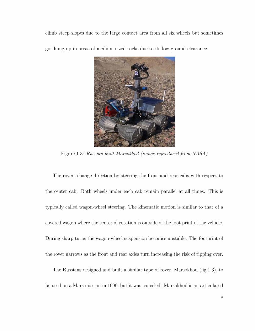
Figure 1.3: Russian built Marsokhod (image reproduced from NASA)
The rovers change direction by steering the front and rear cabs with respect to
the center cab. Both wheels under each cab remain parallel at all times. This is
typically called wagon-wheel steering. The kinematic motion is similar to that of a
covered wagon where the center of rotation is outside of the foot print of the vehicle.
During sharp turns the wagon-wheel suspension becomes unstable. The footprint of
the rover narrows as the front and rear axles turn increasing the risk of tipping over.
The Russians designed and built a similar type of rover, Marsokhod (fig.1.3), to
be used on a Mars mission in 1996, but it was canceled. Marsokhod is an articulated
8
body six wheeled rover but it uses skid steering to change direction [23, 47]. The axes
of the three pairs of wheels never intersect each other. The rover can actively pivot
at the center axle. The front and rear axles are mounted on lever arms which can be
rotated to increase or decrease the distance between each axle [40]. Marsokhod can
use this combined with actively pivoting at the center axle to change from wheeled
locomotion to wheel walking locomotion when traveling up steep slopes. The wheel
design is very unique because the inner portion of the wheels taper toward the center
line of the chassis. This effectively eliminates the need for ground clearance because
the bottom of the rover is mostly consumed by the surface of the wheels. The wheels
house the drive motors as well as some of the electronics for control, the on board
science equipment and the batteries. This creates a rover with a very low center of
gravity and ground pressure allowing it to maneuver through many types of terrain.
However, more soil work is done when moving because of the large amount of surface
contact with the wheels eventually using up a lot of energy.
Articulated body rovers require thermal control for each body segment that con-
tains electronics or actuators. Each compartment must be thermally sealed limiting
9
the number of wires that can pass between them. This can also lead to increased
mass from the excess quantity of insulating materials and heating elements.
The articulated body rovers discussed here require many motors and actuators
for mobility. The SLRV and ”Robby” use a motor in each wheel for driving and two
more for steering using eight motors in total. The Marsokhod uses nine motors with
one in each wheel but none for steering. Three are used for wheel walking mode to
increase the rovers’ mobility across sandy regions and up slopes
1.2.3 Rocker-Bogie Suspension
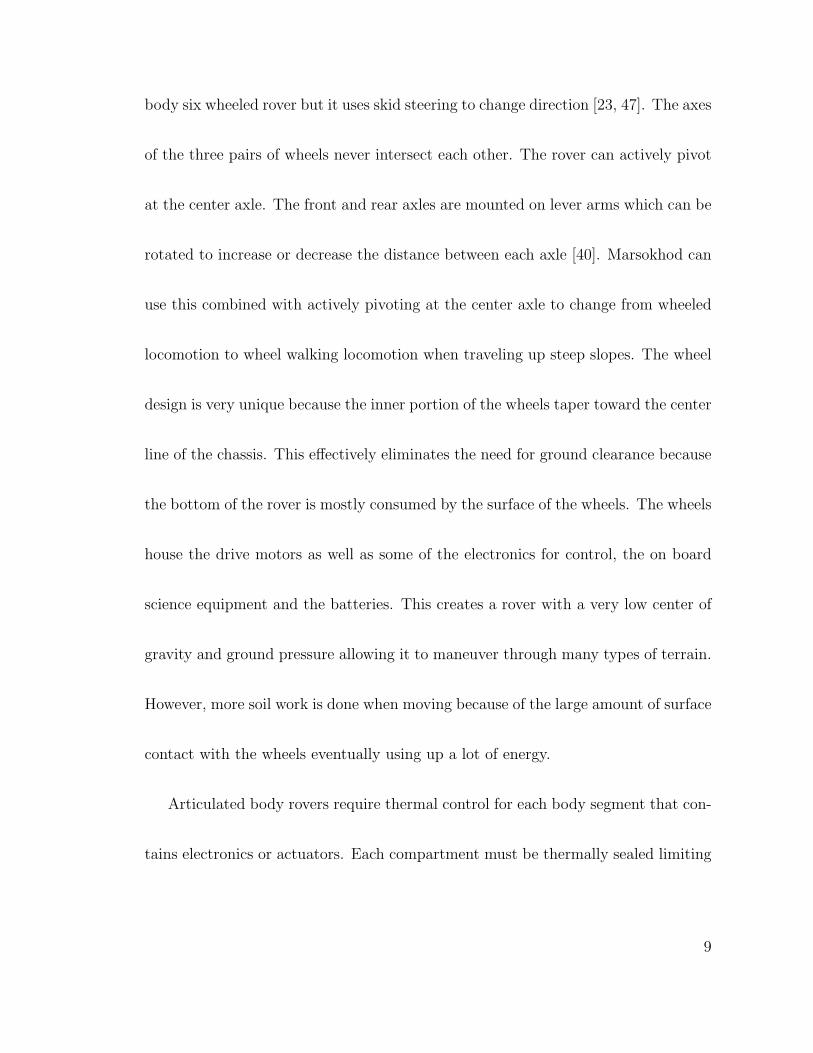
Figure 1.4: NASA’s Pathfinder rover on the 1997 mission and one of the twin MarsExploration Rovers in 2004 (images reproduced from NASA)
The three rovers that have landed on Mars to successfully explore its surface
were developed at NASA (fig.1.4). All three rovers have a six wheel rocker bogie
10
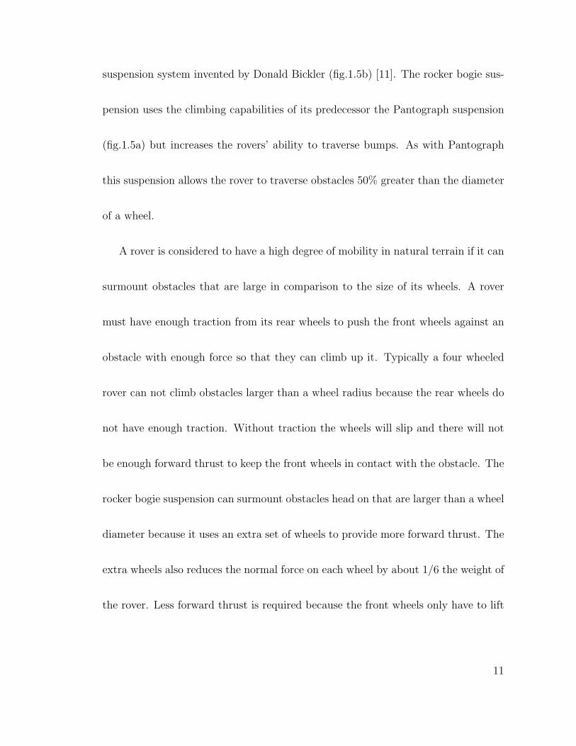
suspension system invented by Donald Bickler (fig.1.5b) [11]. The rocker bogie sus-
pension uses the climbing capabilities of its predecessor the Pantograph suspension
(fig.1.5a) but increases the rovers’ ability to traverse bumps. As with Pantograph
this suspension allows the rover to traverse obstacles 50% greater than the diameter
of a wheel.
A rover is considered to have a high degree of mobility in natural terrain if it can
surmount obstacles that are large in comparison to the size of its wheels. A rover
must have enough traction from its rear wheels to push the front wheels against an
obstacle with enough force so that they can climb up it. Typically a four wheeled
rover can not climb obstacles larger than a wheel radius because the rear wheels do
not have enough traction. Without traction the wheels will slip and there will not
be enough forward thrust to keep the front wheels in contact with the obstacle. The
rocker bogie suspension can surmount obstacles head on that are larger than a wheel
diameter because it uses an extra set of wheels to provide more forward thrust. The
extra wheels also reduces the normal force on each wheel by about 1/6 the weight of
the rover. Less forward thrust is required because the front wheels only have to lift
11
1/3 of the weight of the rover. Together the rear four wheels have enough traction
to keep the rover from slipping [10].
(a) Pantograph (b) Rocker-Bogie
Figure 1.5: Link style mobility systems (images reproduced from NASA)
Each side of the suspension has two links, a main rocker and a forward bogie.
A wheel and steering mechanism is attached to one end of the main rocker. The
opposite end is connected to the forward bogie through a passive pivot joint. A
steering mechanism is attached to each end of the forward bogie with the pivot
mounted in-between. The two sides of the suspension are connected to a single
body from a point on each main rocker. The length of the rockers and bogies and
the position of each joint are defined to distribute the weight of the body on the
wheels with the lowest normal force acting on the front pair. With more normal force
12
on the rear wheels there is more traction to push the front pair over an obstacle.
Unfortunately this works when the rover is moving in the forward direction only.
There is a possibility that the rover may drive into an area that it can not back out
of. A closer look at the MER rover will show that the suspension is on backwards
so that the rover can back out of anything it drives into.
The body of Sojourner is kept stable at the average angle between both sides of
the suspension with a differential linkage. The linkage is connected to both main
rockers and pinned at the center on the back of the body. It assures that all six
wheels have relatively constant loads on them at all times which is a major advantage
of an un-sprung suspension system.
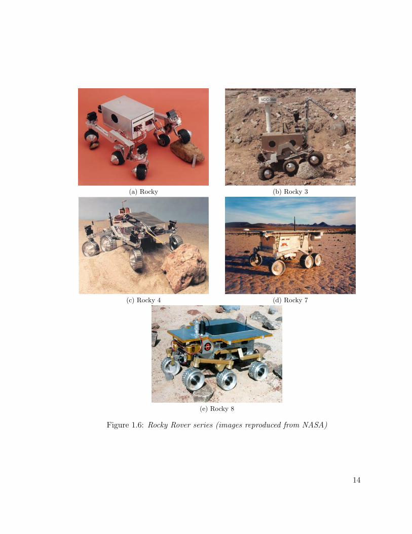
There are a few different configurations of the rocker bogie but they all have six
wheels connected by four links. The series of “rocky” rovers was used to identify
what configuration would work best in Martian conditions. The first Rocky (fig.1.6),
Rocky 3, and Rock 8 use a gear differential between the two suspension sides. So-
journer (fig.1.4), Rocky 4 (fig.1.6c), and Rocky 7 (fig.1.6d) use an external linkage
differential to free up space inside the body [29]. The suspension geometry of Rocky
7 is modified by moving the middle wheels forward and eliminating the steering
13
(a) Rocky (b) Rocky 3
(c) Rocky 4 (d) Rocky 7
(e) Rocky 8
Figure 1.6: Rocky Rover series (images reproduced from NASA)
14
mechanisms on the front pair of wheels [19, 30]. This design reduces the number of
motors needed for mobility from ten to eight, a motor to drive each wheel and two
for steering the rear pair. It was discovered that a rock can jam the tandem wheels
because of the short distance between them. Rocky 8 also known as FIDO (Field
Integrated Design and Operations) rover has a drive motor in each wheel and has
the ability to steer all six wheels independently [44]. This gives FIDO the ability to
perform a “crabbing” maneuver in which the rover can point all of the wheels in the
direction it would like to travel. Previous versions in the Rocky series can do this
as well but the middle pair of wheels will scuff across the ground because they are
not steerable.
The rocker bogie suspension is capable of a high degree of mobility. It has a
ground clearance larger than a wheel diameter, unlike articulated body vehicles.
The single rigid body is more stable for sensor mounting and thermal control. The
suspension mechanisms and joints are above the wheels reducing the chances that
the rover will get caught on an obstacle. It can also perform multiple types of
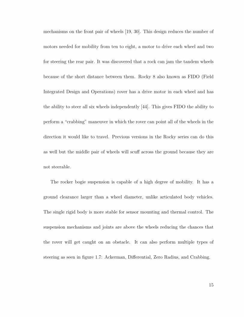
steering as seen in figure 1.7: Ackerman, Differential, Zero Radius, and Crabbing.
15
(a) Crabbing (b) Zero radius (c) Ackerman (d) Differential/Skid
Figure 1.7: Changing direction
This mobility system requires that each wheel be driven by a separate motor
and steering mechanism, increasing the overall complexity. Rovers that use the
rocker bogie suspension can have 10 or 12 motors just for mobility all of which are
exposed to the environment including the drive train. Harmonic drives coupled to
the motors are used to increase torque rather than planetary or spur gear boxes
because they save space and weight. During operation they have high static friction
and can lock up in cold temperatures which will overload the motors causing them
to fail prematurely. Sojourner had heating units on each motor to keep them within
the operating limits in fear that the extreme cold of the Martian atmosphere might
damage them [10].
16
1.2.4 Four Wheel Suspensions
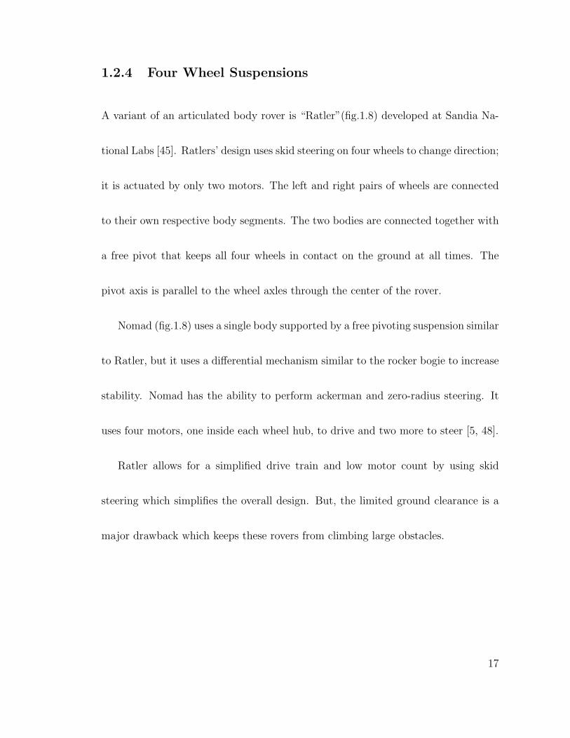
A variant of an articulated body rover is “Ratler”(fig.1.8) developed at Sandia Na-
tional Labs [45]. Ratlers’ design uses skid steering on four wheels to change direction;
it is actuated by only two motors. The left and right pairs of wheels are connected
to their own respective body segments. The two bodies are connected together with
a free pivot that keeps all four wheels in contact on the ground at all times. The
pivot axis is parallel to the wheel axles through the center of the rover.
Nomad (fig.1.8) uses a single body supported by a free pivoting suspension similar
to Ratler, but it uses a differential mechanism similar to the rocker bogie to increase
stability. Nomad has the ability to perform ackerman and zero-radius steering. It
uses four motors, one inside each wheel hub, to drive and two more to steer [5, 48].
Ratler allows for a simplified drive train and low motor count by using skid
steering which simplifies the overall design. But, the limited ground clearance is a
major drawback which keeps these rovers from climbing large obstacles.
17
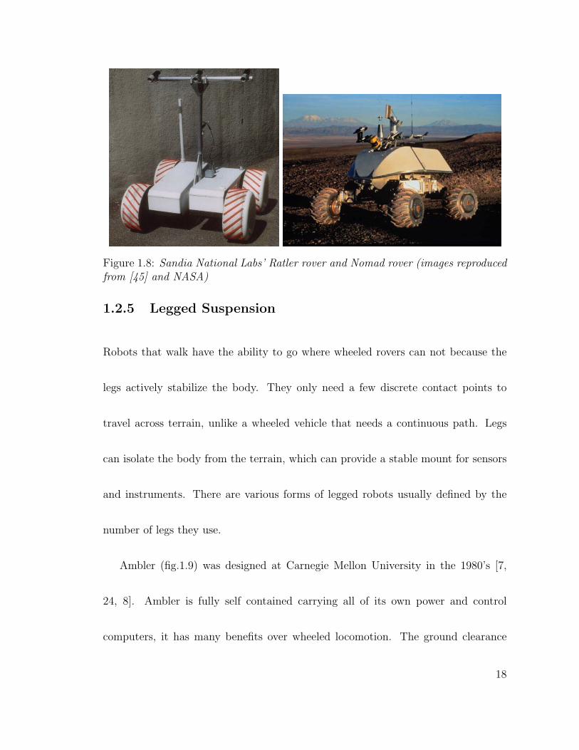
Figure 1.8: Sandia National Labs’ Ratler rover and Nomad rover (images reproducedfrom [45] and NASA)
1.2.5 Legged Suspension
Robots that walk have the ability to go where wheeled rovers can not because the
legs actively stabilize the body. They only need a few discrete contact points to
travel across terrain, unlike a wheeled vehicle that needs a continuous path. Legs
can isolate the body from the terrain, which can provide a stable mount for sensors
and instruments. There are various forms of legged robots usually defined by the
number of legs they use.
Ambler (fig.1.9) was designed at Carnegie Mellon University in the 1980’s [7,
24, 8]. Ambler is fully self contained carrying all of its own power and control
computers, it has many benefits over wheeled locomotion. The ground clearance
18
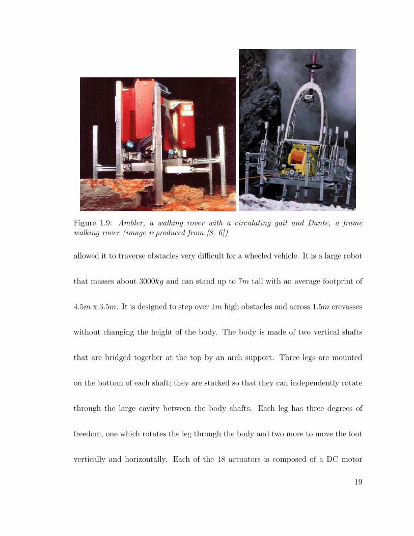
Figure 1.9: Ambler, a walking rover with a circulating gait and Dante, a framewalking rover (image reproduced from [8, 6])
allowed it to traverse obstacles very difficult for a wheeled vehicle. It is a large robot
that masses about 3000kg and can stand up to 7m tall with an average footprint of
4.5m x 3.5m. It is designed to step over 1m high obstacles and across 1.5m crevasses
without changing the height of the body. The body is made of two vertical shafts
that are bridged together at the top by an arch support. Three legs are mounted
on the bottom of each shaft; they are stacked so that they can independently rotate
through the large cavity between the body shafts. Each leg has three degrees of
freedom, one which rotates the leg through the body and two more to move the foot
vertically and horizontally. Each of the 18 actuators is composed of a DC motor
19
assembly with a spur gearbox, encoder and a fail safe brake. The linear motion of
the vertical and horizontal links is produced by a rack and pinion mechanism. The
feet include a six axis force sensor to detect ground contact and lift off.
Ambler is a unique walking robot in that it uses a “circulating” gait that re-
duces the number of footfalls when compared to a “follow-the-leader” gait [8]. The
circulating gait begins when the rear most leg is lifted from the ground and both
vertical and horizontal links are retracted completely. The leg then rotates through
the middle of the body where it is placed on the ground in front of the supporting
legs. Ambler can turn in place and move laterally with an insect style “ratcheting”
gait where the legs do not pass through the body [8]. The circulating gait requires
each leg to spin more than 360o therefore slip-rings are used to pass power and
information between the leg sensors and control system.
Theoretically the circulating gait should be more energy efficient than a wheeled
rover because the center of gravity is held at constant height above varying terrain.
The energy lost from interacting with the terrain was thought to be less than a
wheeled rover because Ambler only uses discrete footholds. However, once the weight
is taken off of one leg in order to take a step the remaining legs have to support
20
more weight. This causes the robot to sink into the ground eventually having to
lift itself up with every step. It is said that the robot seemed to be always walking
up stairs, continuously burning energy [35]. It uses 600W to power all 18 actuators
that move the body forward at a top speed of 7.5 cms
averaging about 35 cmminute
over
rough terrain [24].
Dante (fig.1.9)is a 770kg eight legged robot designed to repel down steep slopes
with the assistance of a tether and winch mechanism [6, 2]. It has four legs attached
to the body and another four mounted to an actuated sub frame. On flat ground
Dante can climb a 1.3m step and a 1.0m step while going down a 30o slope. The
rover stabilizes itself with one set of legs while the other set is advanced one step.
This type of locomotion is called frame-walking. It is used to reduce the number of
degrees of freedom on each leg, which will reduce the number of actuators. Each
leg is composed of a pantograph linkage and moves only in the vertical direction
to conform to height changes in the terrain relative to the rover body. Turning
is accomplished during a step when one set of legs is lifted and the corresponding
frame is rotated toward the new heading. Dante uses 11 actuators to move the body
21
forward at 1 cms
with a tether length of 300m. The tether incorporates power and
data lines because it can not carry its own 2000W power supply.
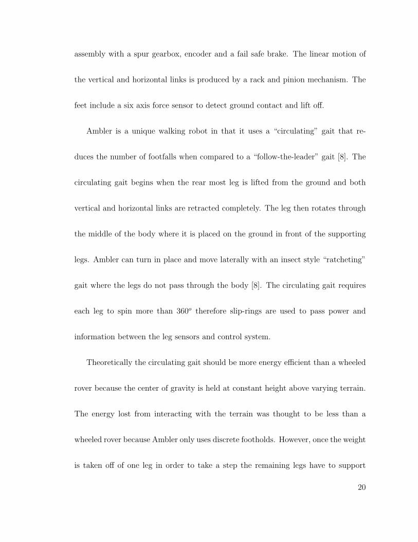
Figure 1.10: Genghis and Attila biologically inspired hexapod robots (image repro-duced from MIT AI lab)
Smaller legged robots that mass only a few kilograms commonly use biologically
inspired designs. They use springs and elastic materials to store and release energy
when walking to improve efficiency and stability [42]. Genghis (fig.1.10) is a hexapod
with two degree of freedom legs meaning that each leg can lift and swing indepen-
dently [12]. Attila (fig.1.10) is an updated version of Genghis, each leg has three
degrees of freedom. It also has a single global degree of freedom that keeps all of
the legs vertical. This allows Attila to climb steeper slopes by keeping the center of
gravity over the footprint of the robot [1]. In the event that Attila flips over all of the
legs can rotate 180o to continue walking, a gyro compass is used to indicate which
direction is up. Genghis and Attila use back-drivable actuators to reduce mass, but
22
they require power even when standing still to keep the body off the ground. The
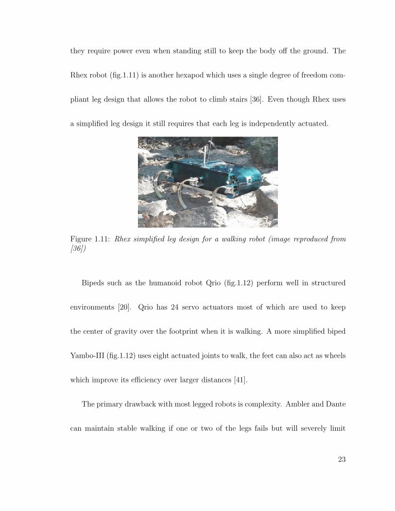
Rhex robot (fig.1.11) is another hexapod which uses a single degree of freedom com-
pliant leg design that allows the robot to climb stairs [36]. Even though Rhex uses
a simplified leg design it still requires that each leg is independently actuated.
Figure 1.11: Rhex simplified leg design for a walking robot (image reproduced from[36])
Bipeds such as the humanoid robot Qrio (fig.1.12) perform well in structured
environments [20]. Qrio has 24 servo actuators most of which are used to keep
the center of gravity over the footprint when it is walking. A more simplified biped
Yambo-III (fig.1.12) uses eight actuated joints to walk, the feet can also act as wheels
which improve its efficiency over larger distances [41].
The primary drawback with most legged robots is complexity. Ambler and Dante
can maintain stable walking if one or two of the legs fails but will severely limit
23
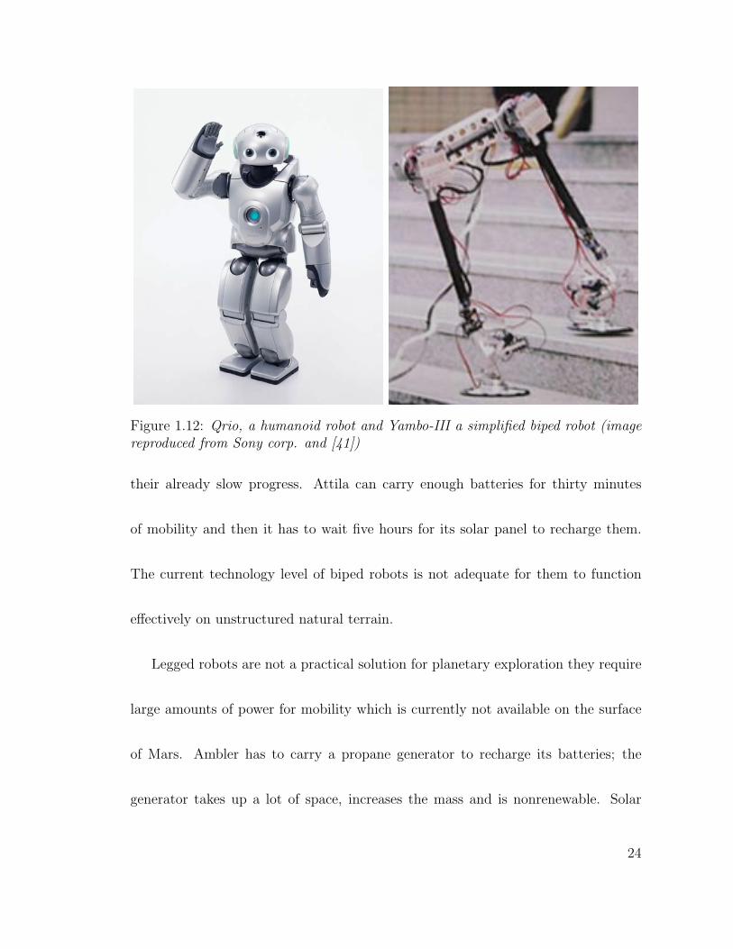
Figure 1.12: Qrio, a humanoid robot and Yambo-III a simplified biped robot (imagereproduced from Sony corp. and [41])
their already slow progress. Attila can carry enough batteries for thirty minutes
of mobility and then it has to wait five hours for its solar panel to recharge them.
The current technology level of biped robots is not adequate for them to function
effectively on unstructured natural terrain.
Legged robots are not a practical solution for planetary exploration they require
large amounts of power for mobility which is currently not available on the surface
of Mars. Ambler has to carry a propane generator to recharge its batteries; the
generator takes up a lot of space, increases the mass and is nonrenewable. Solar
24
arrays would be too large and the politics surrounding radioisotope thermoelectric
generators (RTG’s) make them difficult to launch due to their potentially lethal
power source.
1.3 Design Goals for Mars Rovers
The primary function of a rover on the surface of Mars is to place the instruments it
carries in areas designated by the scientific community on Earth. The design param-
eters for SR-II came from the project sponsor Malin Space Science Systems (MSSS).
Scientists at MSSS came up with the requirements based on information gained from
images taken by the Mars Global Surveyor and Mars Odyssey missions. The images
show that a rover capable of traversing tens of kilometers during a month’s time
will be able to visit multiple science outcrops outside of the landing ellipse. These
specific outcrops could be defined prior to landing. To answer questions about the
history of the planet the rover will have to conduct science on multiple geological
landmarks that could be many kilometers apart. These specified outcrops will be
located within varying types of terrain or at the interface between them. The rover
must be able to traverse large flat plains as well as rock covered areas that require
25
a high degree of mobility. The mobility system must be reliable and remain at a
relatively high efficiency for tens kilometers of operation to achieve all of the science
objectives [22].
MSSS specified that the rover be between 20 to 30kg. A small rover is capable of
tens of kilometers using solar energy equivalent to the amount seen on the surface of
Mars [33]. In order to maintain a long distance pace the rover should average about
15 cms
and consume less than 100W of power. To get the rover to Mars it must fit
inside the launch vehicle. The launch configuration footprint must not exceed one
square meter (1m2) and half a meter (0.5m) high including the solar panel.
1.4 Terrain and Environment
The various spacecraft that have landed on Mars provide sufficient evidence that
its surface is hard enough to support a small mobile vehicle. The images taken
from the surface indicate that it contains geological formations similar to places on
Earth. Some have stated that the areas resemble places in the deserts of Arizona
and California where there is little vegetation. The images from the Viking Landers
in the 1970’s (fig.1.13) and the Pathfinder mission in 1997 show rolling hills littered
26
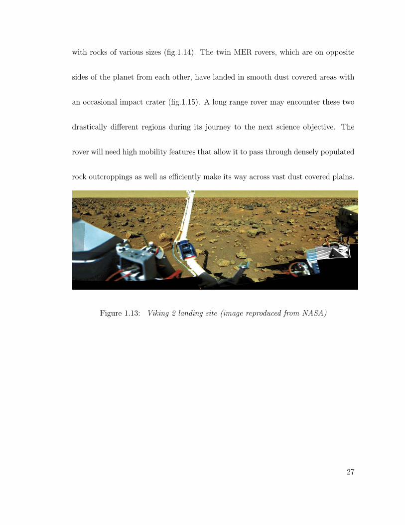
with rocks of various sizes (fig.1.14). The twin MER rovers, which are on opposite
sides of the planet from each other, have landed in smooth dust covered areas with
an occasional impact crater (fig.1.15). A long range rover may encounter these two
drastically different regions during its journey to the next science objective. The
rover will need high mobility features that allow it to pass through densely populated
rock outcroppings as well as efficiently make its way across vast dust covered plains.
Figure 1.13: Viking 2 landing site (image reproduced from NASA)
27
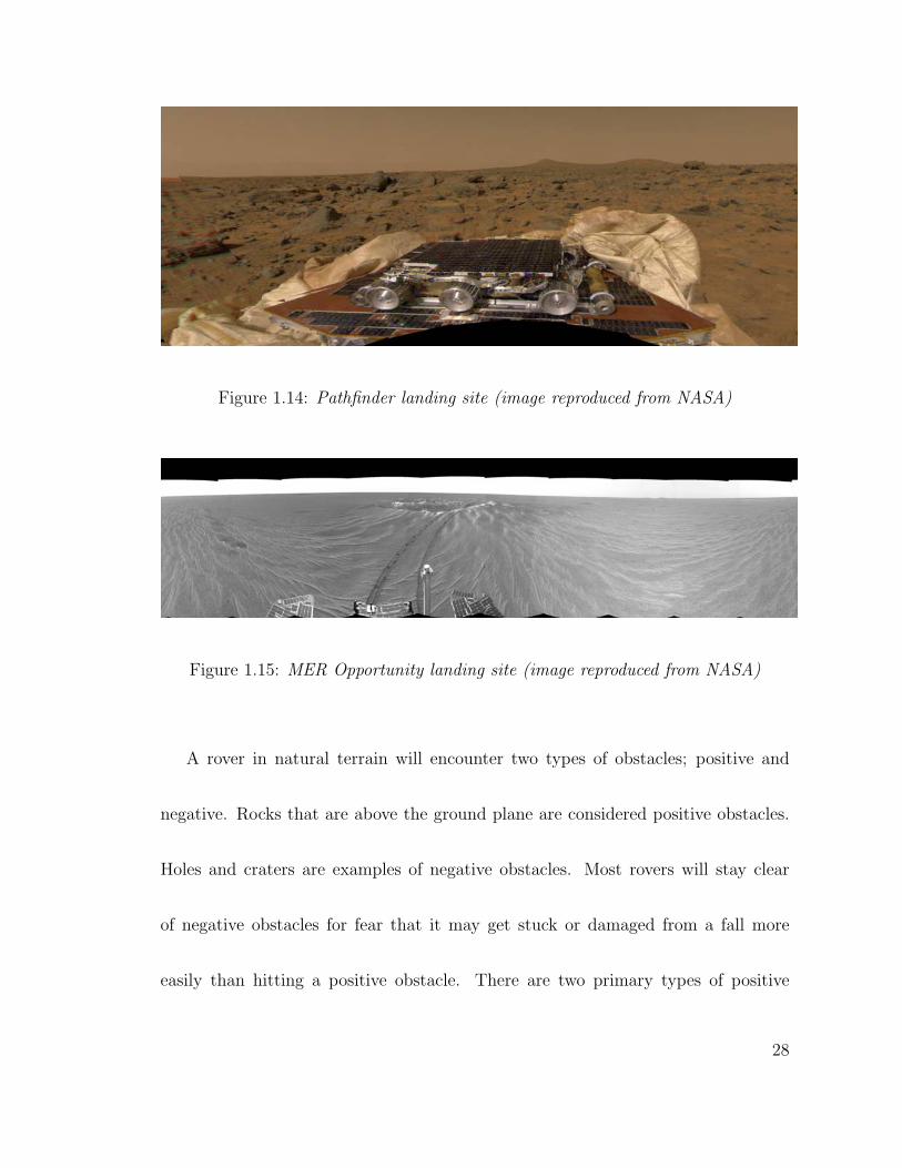
Figure 1.14: Pathfinder landing site (image reproduced from NASA)
Figure 1.15: MER Opportunity landing site (image reproduced from NASA)
A rover in natural terrain will encounter two types of obstacles; positive and
negative. Rocks that are above the ground plane are considered positive obstacles.
Holes and craters are examples of negative obstacles. Most rovers will stay clear
of negative obstacles for fear that it may get stuck or damaged from a fall more
easily than hitting a positive obstacle. There are two primary types of positive
28
obstacles that a rover may come across; bumps and steps. A bump is an obstacle
that the rover can drive over a wheel at a time like a rock shorter in length than the
wheelbase of the rover. During the traversal of this type of obstacle the remaining
wheels maintain contact with the original ground plane. A step obstacle will raise
the entire vehicle to a new ground plane. As the rover traverses a step the front
wheels will remain on top of the obstacle once it has climbed it. The rear wheels will
then have to be pulled up. Of course the rover must be able to sense if the obstacle
is surmountable before attempting this.
1.5 Four vs. Six wheels
1.5.1 Are six wheels overkill?
On Sol 35 Sojourner was commanded to head to a new science objective called the
Rock Garden, an outcropping of large rocks to be analyzed by the alpha proton
X-ray spectrometer on board the rover. When the images from the Lander were
seen at the end of the day Sojourner had parked herself in-between two large rocks
named Wedge and Hassock, not on the commanded route. The odometer sensors
29
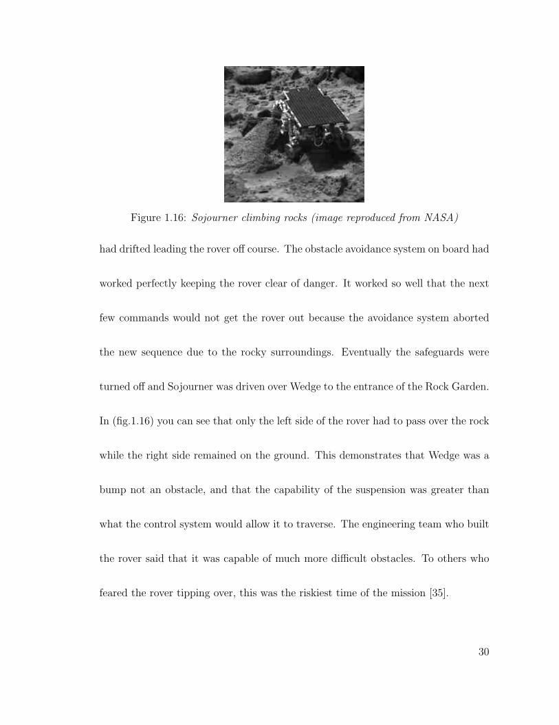
Figure 1.16: Sojourner climbing rocks (image reproduced from NASA)
had drifted leading the rover off course. The obstacle avoidance system on board had
worked perfectly keeping the rover clear of danger. It worked so well that the next
few commands would not get the rover out because the avoidance system aborted
the new sequence due to the rocky surroundings. Eventually the safeguards were
turned off and Sojourner was driven over Wedge to the entrance of the Rock Garden.
In (fig.1.16) you can see that only the left side of the rover had to pass over the rock
while the right side remained on the ground. This demonstrates that Wedge was a
bump not an obstacle, and that the capability of the suspension was greater than
what the control system would allow it to traverse. The engineering team who built
the rover said that it was capable of much more difficult obstacles. To others who
feared the rover tipping over, this was the riskiest time of the mission [35].
30
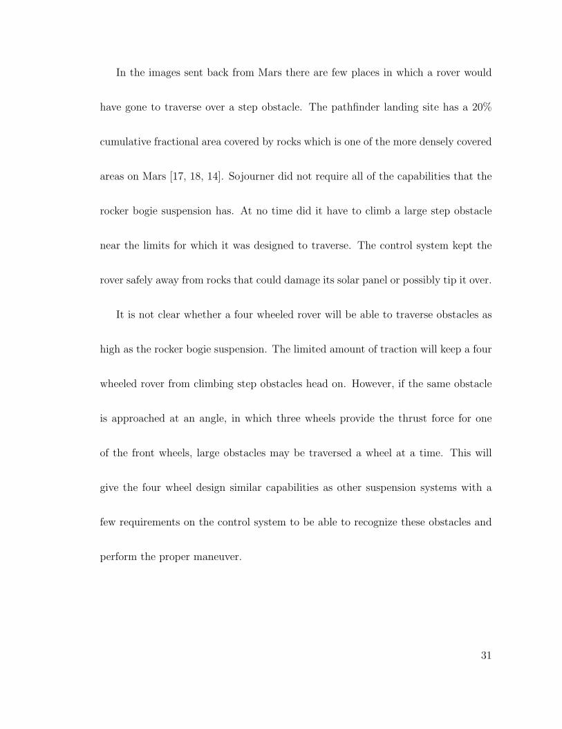
In the images sent back from Mars there are few places in which a rover would
have gone to traverse over a step obstacle. The pathfinder landing site has a 20%
cumulative fractional area covered by rocks which is one of the more densely covered
areas on Mars [17, 18, 14]. Sojourner did not require all of the capabilities that the
rocker bogie suspension has. At no time did it have to climb a large step obstacle
near the limits for which it was designed to traverse. The control system kept the
rover safely away from rocks that could damage its solar panel or possibly tip it over.
It is not clear whether a four wheeled rover will be able to traverse obstacles as
high as the rocker bogie suspension. The limited amount of traction will keep a four
wheeled rover from climbing step obstacles head on. However, if the same obstacle
is approached at an angle, in which three wheels provide the thrust force for one
of the front wheels, large obstacles may be traversed a wheel at a time. This will
give the four wheel design similar capabilities as other suspension systems with a
few requirements on the control system to be able to recognize these obstacles and
perform the proper maneuver.
31
1.5.2 Why 4 wheels?
Driving the Lunokhods across the lunar terrain with its eight wheeled skid steering
suspension proved to be very successful in conducting science on another planet.
Since then various other rovers have been designed in order to increase mobility and
efficiency. Many of these efforts have not been focused on simplifying the rover de-
sign. The primary purpose of a mobility system is to carry the on board instruments
across the unstructured terrain, if a large portion of the allotted mass and power is
taken up by the mobility system then fewer instruments can be carried. In the past
few decades the complexity of rover mobility systems has increased. The Lunokhod
rovers required eight motors for mobility and 30 years later the rocker-bogie suspen-
sion requires ten. New failsafe technology is being added to current rover designs
to increase their life span [21]. It is possible that adding this technology may fur-
ther increase mass and complexity of the drive train. Efforts should be focused on
increasing drive train reliability by simplifying the overall system.
The autonomous control system on board the rover will limit the size of obstacles
it is allowed to traverse to keep the robot from getting hung up or flipped over,
32
terminating its mission. So, why does the mobility system need to exceed these limits
to such extreme amounts? A four wheeled rover using skid steering can achieve the
same goals as the six or eight wheeled mobility systems described previously. Fewer
motors are required and the suspension consumes less mass and volume leaving more
room for instruments and power devices.
Figure 1.17: Four wheeled Solar Rover-II
Solar Rover-II is a self contained solar powered rover designed for long distance
travel (fig.1.17). The design combines many of the positive values from the previously
discussed rovers while using four wheels to reduce the motor count of the system. The
Lunokhod rovers have inspired its skid steering mode of operation to further simplify
33
the design by eliminating the need for extra steering motors and mechanisms. The
left and right pairs of wheels are mechanically linked so that all four wheels are
powered by two motors similar to Ratler. On a flight rover the body is heated
to protect the control system, batteries, and other various power circuits from the
cold Martian atmosphere like that used on Sojourner. The life span of the motors
and gearboxes can be increased because they are mounted inside of the body which
will keep the lubrication from hardening. This also reduces the number of external
electronic connections because the sensors that monitor the suspension movements
are inside the body. The suspension itself lifts the body above the wheels creating
a large amount of ground clearance. Both sides are connected together through a
passive gear differential to increase the stability of the body similar to the rocky
rovers. While this design does not have all of the mobility characteristics of the six
wheeled rocky rovers I believe it has the ability to accomplish more science goals.
1.6 Organization of Thesis
The remaining part of this thesis describes the SR-II rover in more detail. Chapter
two is a walk through the mechanical design of the body, suspension, and drive
34
train. It also includes other components that are used on the rover during operation
such as power and control devices. A field test which took place at the Salton Sea
desert in southern California and a laboratory test to better quantify the abilities of
the design are included in chapter three. Experimental results and conclusions are
presented in chapter four.
35
Chapter 2
Solar Rover-II Mechanical System
The body, drive train, suspension, and wheels are the major mechanical elements
that make up SR-II. The body houses the electronics and batteries and serves as a
mounting place for the sensor suite. The drive train transfers torque from the motors
to the wheels using gear trains connected by drive shafts which are supported by
the suspension. The suspension lifts the body above the wheels to maximize ground
clearance improving mobility over obstacles. SR-II uses a differential mechanism to
maintain a relatively even weight distribution on all wheels when driving over uneven
terrain. These structures are designed to be as compact as possible to conserve space
while protecting the internal components against foreign debris and collisions with
obstacles.
36
2.1 SR-II design goals
The primary design goal for the SR-II rover is simplification. The mobility system
used to get the rover to its destination must be energy efficient, light weight, and
robust. In order to directly affect each of these criteria the number of motors must
be reduced and their location must be carefully selected. The mechanisms that make
up the drive line should be based on simple components that will increase reliability.
An un-sprung suspension allows for a light weight design while maintaining good
mobility characteristics. This is possible because the top speed of the rover will
never be fast enough for the tires to leave contact with the ground while driving
over bumps.
The design parameters for SR-II came from the project sponsor Malin Space
Science Systems (MSSS). Geologists have based these parameters on information
gained from images of Mars. The images show that a rover that can traverse 10cm
high obstacles will be able to conduct science on specific geological landmarks that
may answer questions about the age and origin of the planet. In order to get the
rover to Mars it must fit inside of the launch vehicle. The launch configuration
37
footprint must not exceed one square meter (1m2) and a height of 0.5m including
the solar panel. These dimensions were also from our sponsor MSSS.
2.2 Main Body
The first major decision when designing a rover is to specify the type of body struc-
ture. The main purpose of the body on a flight rover is to house anything that
must be kept within a nominal operating temperature, such as the batteries and
electronics. The temperature on Mars is cold, the average is around −55oC with
highs up to 27oC (80oF ) and lows down to −133oC (−207oF ) [3]. The body will
act as a thermal insulating shell to keep the electronics inside isolated from the cold
outside. The current Mars rovers use an ultra-light material called Silica Aerogel in
the walls of the body. Aerogel has a very low thermal conductivity (0.017 Wm·K ) due
to its porous structure and is the lightest rigid material known to man (0.1 gcm3 ) mak-
ing it an ideal material for space applications [4]. However, the body is also known
as the chassis of the rover which is an integral part of the suspension by passing
forces across its structure. The mechanical properties of Aerogel are similar to that
of glass, it is very brittle and cannot handle large shock loads without fracturing
38
into many pieces. A stronger more ductile material such as Aluminum or Titanium
is used to withstand the various forces. The thermal conductivity for these metals
is thousands of times higher and will easily dissipate the heat inside. Therefore,
the walls of the body are a composite structure which combines the properties of
these different materials. The walls of Sojourner are very similar to the walls of an
ordinary wood frame house, where the wooden studs in the home are replaced with
metal beams to support the load. The space between the beams is then filled with
Aerogel as the insulation. Finally the walls are laminated in gold foil which helps
reflect heat transferred by infrared light [35].
A single body design has many advantages over the three segment articulated
body rovers. Thermal control is more efficient, electrical connections are reduced,
and sensor mounting is simplified. Fewer heaters are needed to keep the electronics
warm because they are all mounted within a single insulated shell. A multi-bodied
rover will require a heater in each compartment that contains anything that must
be kept warm. These heaters will also have to run longer because the surface area
exposed to the atmosphere is larger than a single body with an equal amount of
volume. The wiring harness is simplified by keeping the electronics mounted to one
39
rigid structure. Heat loss is minimized and reliability is increased by reducing the
number of interconnections to any external motors and sensors. The single body
provides a stable platform for sensors and science payloads as well as a base support
for a robotic manipulation device like an arm.
The first major decision when designing SR-II was to use a single body design
similar to Lunokhod and the rocky rovers. The body on SR-II is primarily used to
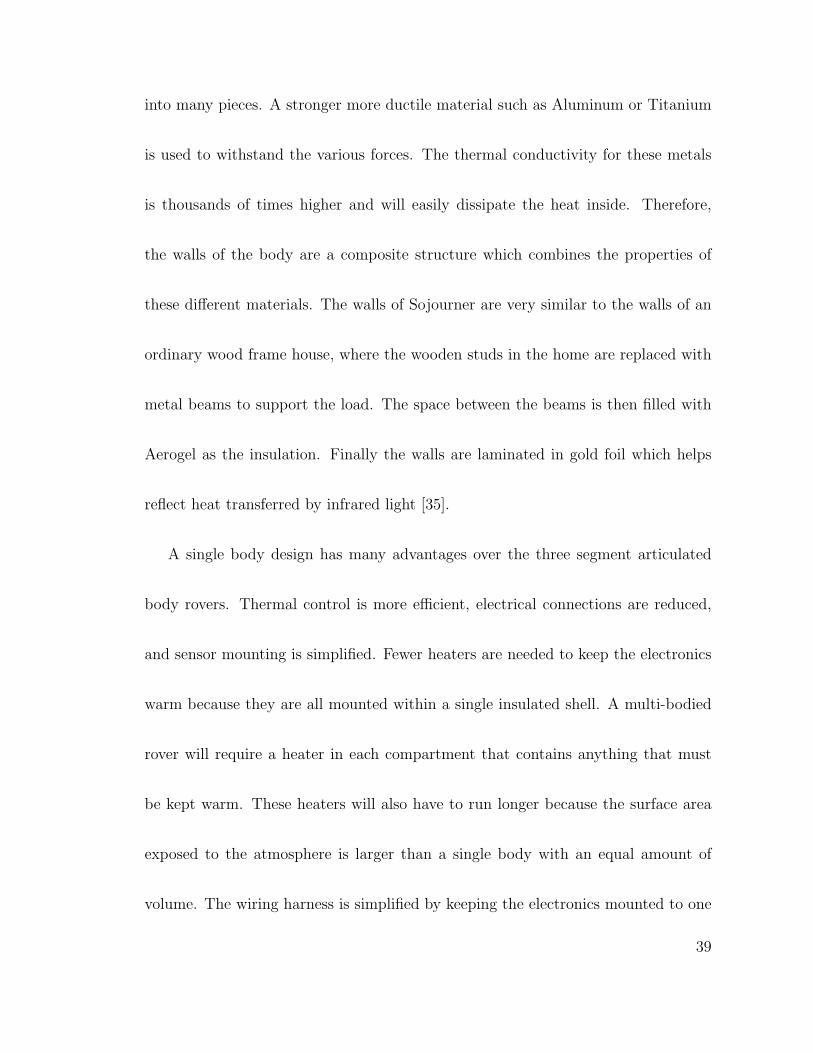
serve other functions but does help to protect the electronics from the summer heat
during the field test.
Figure 2.1: Solar Rover-II body and solar panel
SR-II’s body (fig.2.1) is a simple open ended rectangular tub 45x35x20cm. The
base, left and right side walls are 10mm thick constructed of laminated aluminum
honeycomb. Aerogel was not used in the construction because thermal insulation is
40
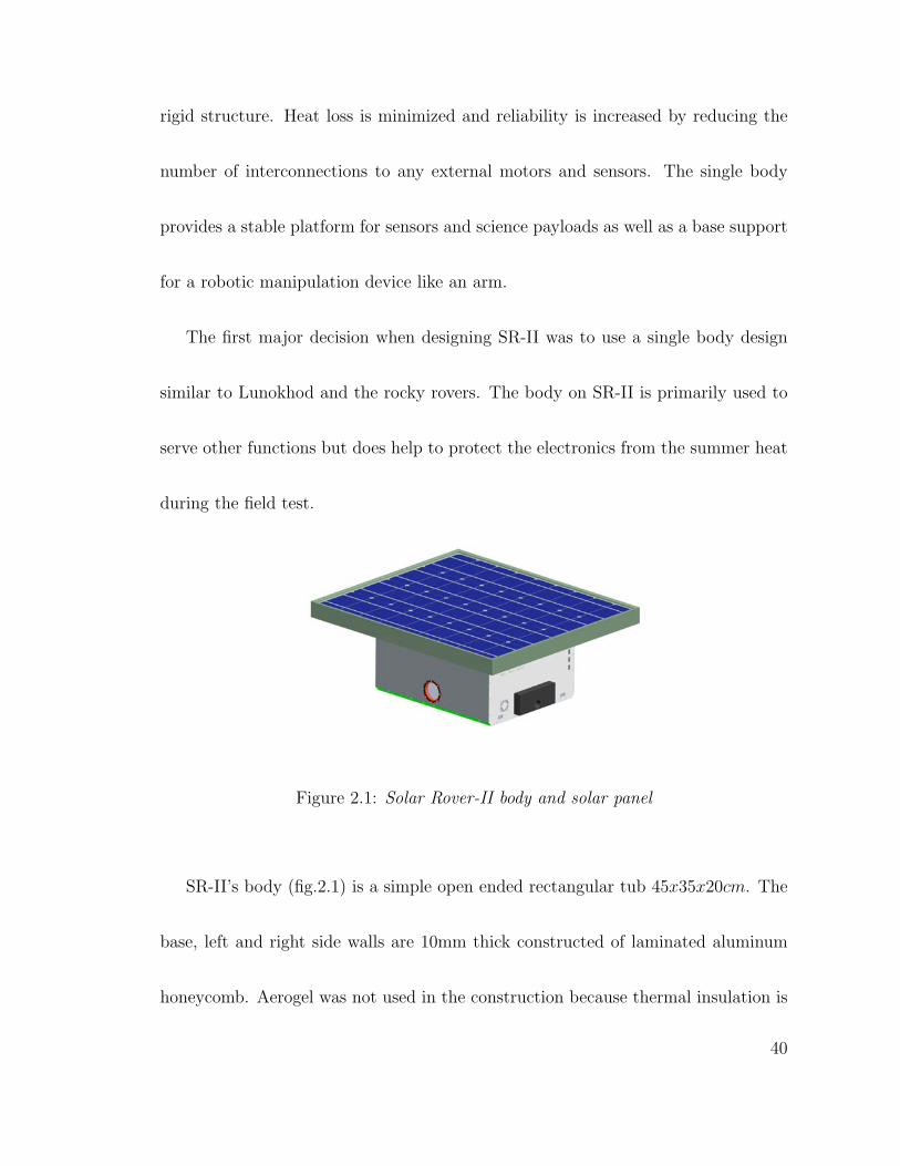
not a major concern for the field test. The sides support the suspension while the
base supports the central differential. The front and rear panels are solid aluminum
plate which are used for mounting various switches, indicators, and connectors for
debugging and monitoring the rover. Some of the optical sensors are mounted to
the front plate. The top of the tub is closed with a removable single glass pane solar
panel attached to a simple space frame.
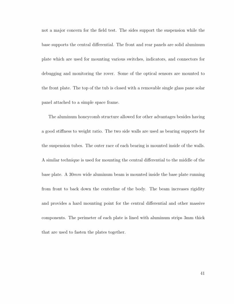
The aluminum honeycomb structure allowed for other advantages besides having
a good stiffness to weight ratio. The two side walls are used as bearing supports for
the suspension tubes. The outer race of each bearing is mounted inside of the walls.
A similar technique is used for mounting the central differential to the middle of the
base plate. A 30mm wide aluminum beam is mounted inside the base plate running
from front to back down the centerline of the body. The beam increases rigidity
and provides a hard mounting point for the central differential and other massive
components. The perimeter of each plate is lined with aluminum strips 3mm thick
that are used to fasten the plates together.
41
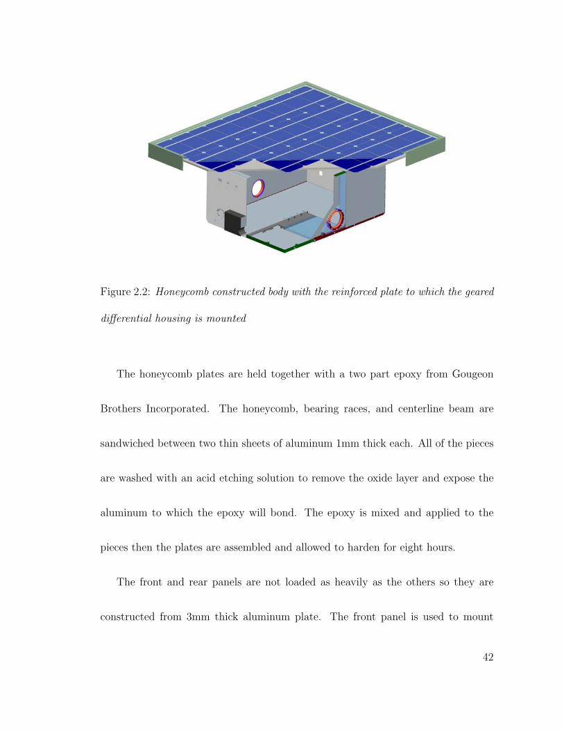
Figure 2.2: Honeycomb constructed body with the reinforced plate to which the geared
differential housing is mounted
The honeycomb plates are held together with a two part epoxy from Gougeon
Brothers Incorporated. The honeycomb, bearing races, and centerline beam are
sandwiched between two thin sheets of aluminum 1mm thick each. All of the pieces
are washed with an acid etching solution to remove the oxide layer and expose the
aluminum to which the epoxy will bond. The epoxy is mixed and applied to the
pieces then the plates are assembled and allowed to harden for eight hours.
The front and rear panels are not loaded as heavily as the others so they are
constructed from 3mm thick aluminum plate. The front panel is used to mount
42
various optical sensors; a stereo camera pair and infrared sensors. The back panel is
used to mount on/off switches, power indicators, debugging connectors, and a DB-9
connector for the magnetic compass. The time required for debugging the control
system will be decreased because access to the internal components is not needed
once they have been mounted.
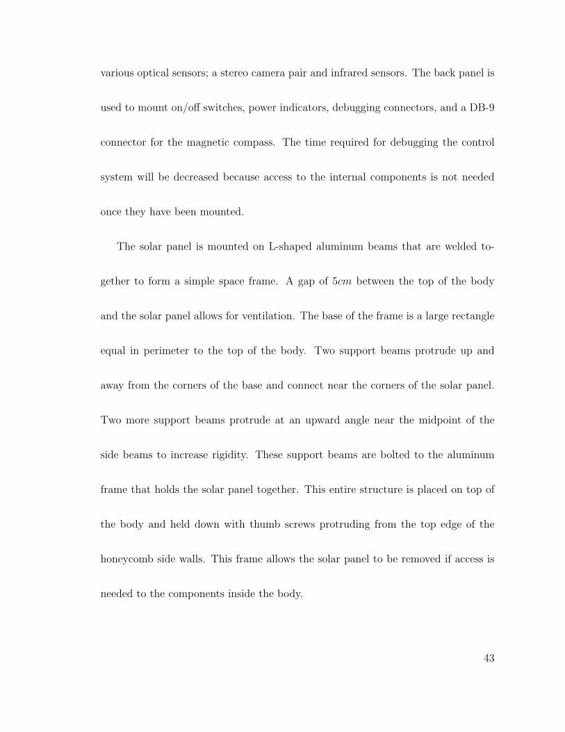
The solar panel is mounted on L-shaped aluminum beams that are welded to-
gether to form a simple space frame. A gap of 5cm between the top of the body
and the solar panel allows for ventilation. The base of the frame is a large rectangle
equal in perimeter to the top of the body. Two support beams protrude up and
away from the corners of the base and connect near the corners of the solar panel.
Two more support beams protrude at an upward angle near the midpoint of the
side beams to increase rigidity. These support beams are bolted to the aluminum
frame that holds the solar panel together. This entire structure is placed on top of
the body and held down with thumb screws protruding from the top edge of the
honeycomb side walls. This frame allows the solar panel to be removed if access is
needed to the components inside the body.
43
2.3 Drive Train
The drive train is a system that transfers the torque output from the motors to
the wheels. A compact light weight design is needed to maintain efficiency and
reduce the power consumed when driving. It must be able to withstand high loads
in forward and reverse directions when the rover is climbing over obstacles for many
kilometers. The thermal expansion and contraction of materials must also be taken
into account, since the temperature swing on a Martian day can be about 100oC [3].
The drive mechanisms must be designed using alloys with low thermal expansion
coefficients so as not to cause part interference.
A design goal for the drive train on SR-II is to keep the motors and gears near the
body so that they could be easily heated on a flight ready model. This will eliminate
the need for a heater near each specific motor/gearbox to keep the lubrication from
hardening and thermal lock-up from the extreme cold. Placing the motors in a
nominal environment will increase their efficiency and operational life.
44
2.3.1 Wheel torque
The wheel diameter and weight of the rover are critical dimensions that affect the
amount of torque required to traverse obstacles. The following assumes that the
wheel has a mechanical grip on the obstacle using the grousers on the tire and does
not slip. This is done to obtain the maximum amount of torque needed. The wheel
diameter is 210mm, defined in [52], based on the dimensions from a similar scale
rover Rocky 8 (fig.1.6e). Only a fraction of the mass of the rover will need to be
lifted by each wheel because all four wheels are always in contact with the ground.
This is an advantage of having a spring less suspension. To be sure that it will have
enough torque each wheel should lift one quarter of the rover’s mass (7.5kg). The
weight of the rover will be calculated using Earth gravity (9.81ms2 ) since all testing
will be done here.
45
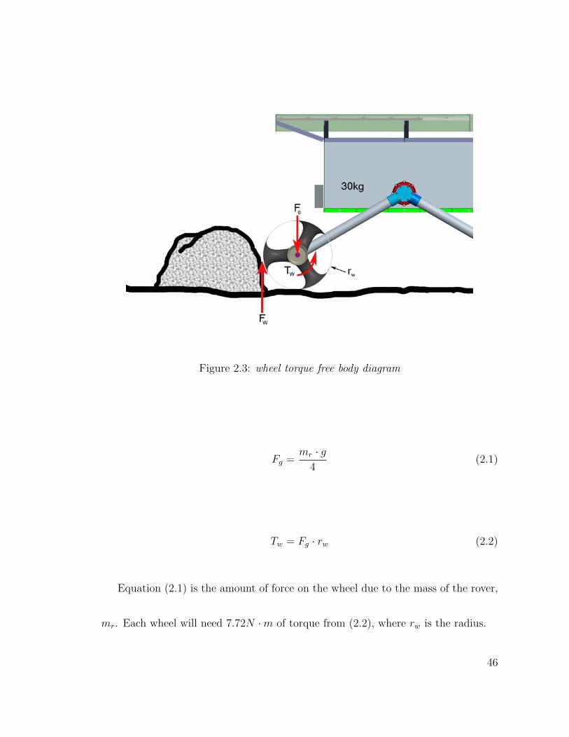
Figure 2.3: wheel torque free body diagram
Fg =mr · g
4(2.1)
Tw = Fg · rw (2.2)
Equation (2.1) is the amount of force on the wheel due to the mass of the rover,
mr. Each wheel will need 7.72N ·m of torque from (2.2), where rw is the radius.
46
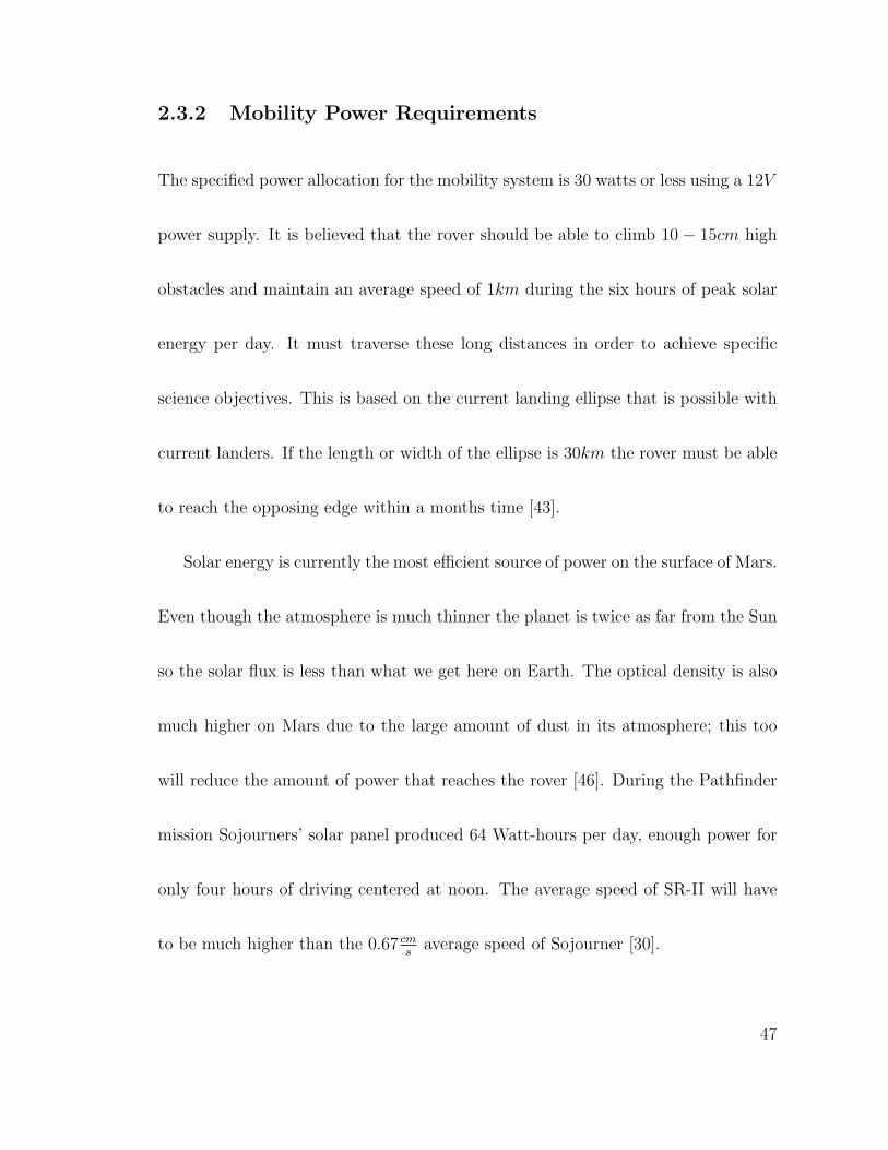
2.3.2 Mobility Power Requirements
The specified power allocation for the mobility system is 30 watts or less using a 12V
power supply. It is believed that the rover should be able to climb 10− 15cm high
obstacles and maintain an average speed of 1km during the six hours of peak solar
energy per day. It must traverse these long distances in order to achieve specific
science objectives. This is based on the current landing ellipse that is possible with
current landers. If the length or width of the ellipse is 30km the rover must be able
to reach the opposing edge within a months time [43].
Solar energy is currently the most efficient source of power on the surface of Mars.
Even though the atmosphere is much thinner the planet is twice as far from the Sun
so the solar flux is less than what we get here on Earth. The optical density is also
much higher on Mars due to the large amount of dust in its atmosphere; this too
will reduce the amount of power that reaches the rover [46]. During the Pathfinder
mission Sojourners’ solar panel produced 64 Watt-hours per day, enough power for
only four hours of driving centered at noon. The average speed of SR-II will have
to be much higher than the 0.67 cms
average speed of Sojourner [30].
47
The maximum amount of power that SR-II will need to traverse 1 kmday
can be
calculated with the following. Assuming that the maximum force retarding forward
progress will be traversing positive obstacles, the velocity can be calculated by;
vr =Wr
Fg · 4(2.3)
where Wr is the 30W ’s of power for mobility and Fg is the retarding force on a
wheel. Using the speed from the following the total power needed for a days driving
can be calculated.
W =Win · 1km
vr
· (1 + Wloss) (2.4)
SR-II will need an average speed of 10.2 cms
and the solar panel must produce
about 89.9W · hr per six hour day. Equation 2.4 includes a 10% loss of power due
to friction in the drive train itself.
Even though the power requirements are 28% higher than what is needed for
Sojourner, SR-II will be driving in Earth’s gravity (9.81ms2 ) rather than Martian
gravity (3.69ms2 ). It will most likely not have such high opposing forces acting on
48
the wheels for long periods of time, reducing power consumption. The path taken
by the rover will not be a straight line as assumed above, so it may take longer for
SR-II to drive a full kilometer toward its objective. However, at 10.2 cms
the rover
would complete its run in 2.7 hours. If the same mission time line is followed as
that of Sojourner’s four hour day than SR-II will have 1.3 hours to make up any lost
ground.
2.3.3 Motors
The placement of the motors in the design is a critical element that can define the
life of the rover. The rocker-bogie suspension design exposes all of the drive motors
including the ones used for steering, to the atmosphere during the entire mission. The
extreme temperature changes can cause parts of the motor to lock-up due to thermal
expansion and contraction of the different types of materials inside them. Having
the motors external also exposes any sensors that are used to measure movement.
Sojourner has ten motors each with an optical encoder. The motors themselves
require two wires to drive but the encoders require at least six, this makes an 80
wire bundle that must be fed into the body where the control system is located. This
49
would cause a large breach in the wall of the body allowing heat to pass through
the copper conductors [35]. The wires are routed across the outside of the body
and down each side of the suspension to their respective motor/sensor assemblies.
They need to flex as the suspension moves in relation to the body, but the cold
temperatures will cause them to stiffen and possibly break.
Current NASA rovers use wheel mounted motors and drive trains. This can
produce a very compact design by using the space already taken up by the inner
portion of the wheels. But, this leaves the motors exposed to the Martian atmosphere
which can degrade their performance as stated above. The MER rover Spirit saw a
large performance drop in its right front drive motor on Sol 184. Without the wheel
being able to spin the engineers on Earth were forced to drive the rover backwards
dragging the wheel.
The motors need to be mounted inside of the body to solve the problems caused
by the cold atmosphere. The rover design can take advantage of this by using heat
produced from the motors to warm the other electronics. The efficiency and life
time of the motors will be higher. The electrical wiring is also simplified because
the optical encoders will be located inside the body as well.
50
There are a few disadvantages to this design though. The drive assemblies will
take up valuable space inside the body. Heat loss may be substantial by having part
of the suspension and drive train protruding though the walls of the body. This is
a drawback with the rocker bogie suspension mounting as well.
The twin motor design of SR-II will cut the number of motors down as well as
the breach through the body wall. One motor on each side of the rover will drive
a pair of wheels. The two left side wheels are powered by one motor and a drive
train, the same for the right side. The motors could not be used for the front and
rear axles because a steering mechanism would be required, complicating the system
with linkages and more motors. However, this will leave the rover with only one
mode of turning, skid steering.
The Lunokhod rovers used this same mode of turning when driving on the moon.
These rovers were capable of driving around obstacles with twice as many wheels
on the ground in very fine grain lunar soil. Skid steering is an easily controllable
mode of changing direction. Point steering as well as turning on an arc is possible
by varying the speed of the motors. It is likely that the power required for skid
turning is higher when compared with the rocker bogie because more soil work will
51
be done with small radius turns. However, it is not clear that this is a penalty when
compared with the rocker bogie energy requirements over long distance traverses.
Figure 2.4: SR-II with motors in place
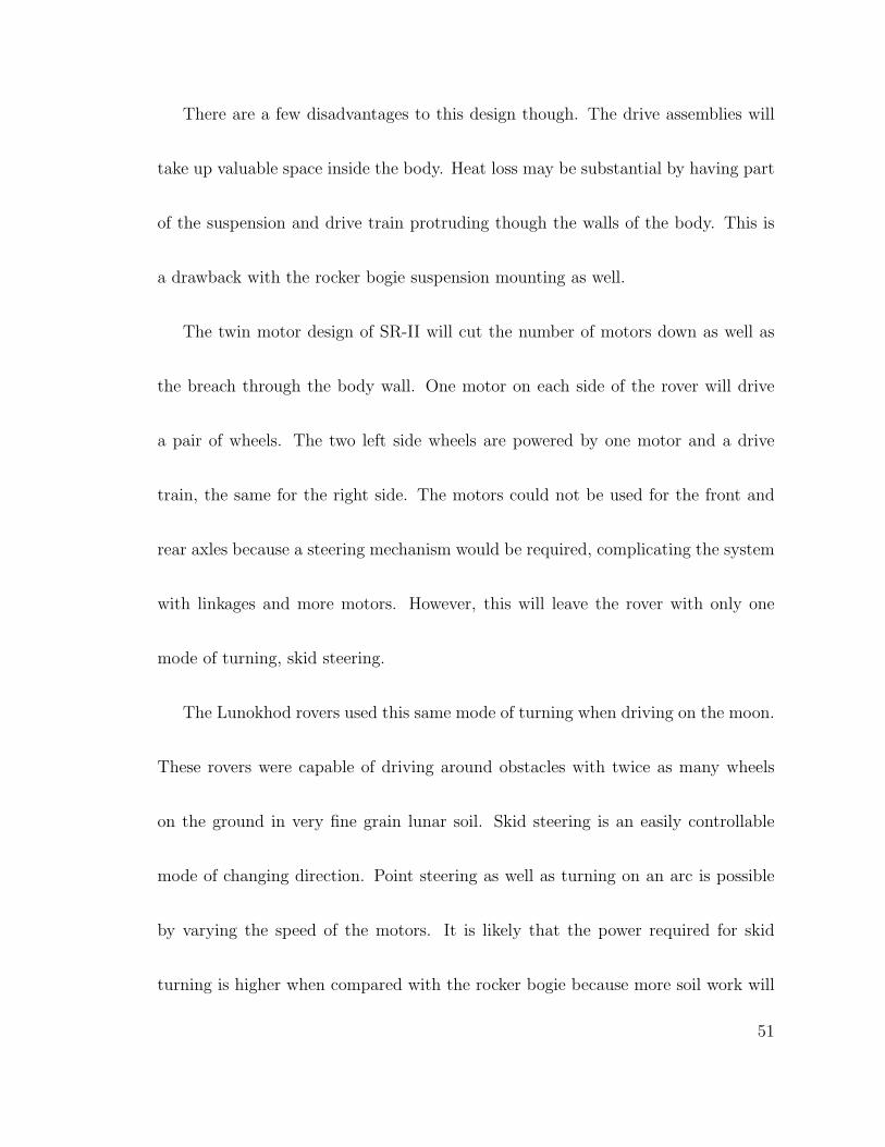
The motors will be placed at the center of the body perpendicular to the side
walls (fig.2.4). The nominal operating speed of the motor is too high (5000 rpm) to
pass directly into the rest of the drive train. A multi stage planetary gear reduction
is used to achieve lower rpm with higher torque. Harmonic drive speed reducers
are not used because they are more susceptible to failure without lubrication. They
require a large amount of torque to free the internal wave generator because of static
friction between itself and the flexspline. This requires more current to pass through
the coils of the motor eventually burning up the graphite brushes or coil.
52
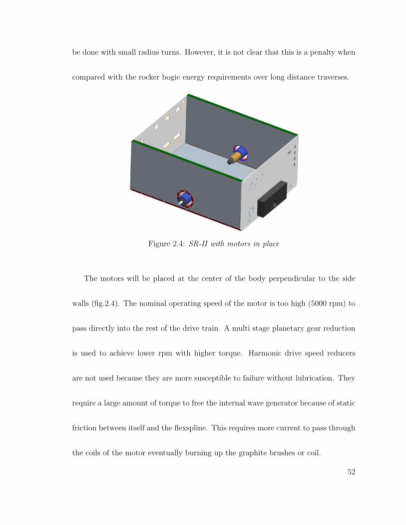
2.3.4 Drive Train Concepts
The drive train will need to be compact so that it can be supported by a suspension
with a small profile to keep clear of any obstacles that the rover encounters. The
general configuration of the suspension will raise the body above the wheels for
maximum ground clearance. A few preliminary drive train concepts were evaluated
for transferring power from the motors to the wheels. To keep the same mobility
characteristics in both forward and backward directions SR-II is symmetric about
the mid plane of the body.
Figure 2.5: Belt drive with tensioning pulleys
A belt drive (fig.2.5) was first discussed for simplicity and to reduce manufac-
turing time. The supporting structure would require few parts, most of which could
53
be machined out of plate reducing setup time and the number of operations. A belt
mechanism does not require lubrication between interconnecting parts therefore it
could be run in a cold environment and maintain high efficiency. A nylon or Kevlar
timing belt would require a large number of idler pulleys to keep it in tension for
torque transfer in both directions with limited backlash. The diameter of these pul-
leys would need to be small in order to be packaged inside of the suspension; this will
cause excessive bending and reduce the life of the belt especially in the cold Martian
environment. The large distance between the wheel pulley and motor pulley could
cause belt ware against the pulley flanges, also decreasing the life of the belt.
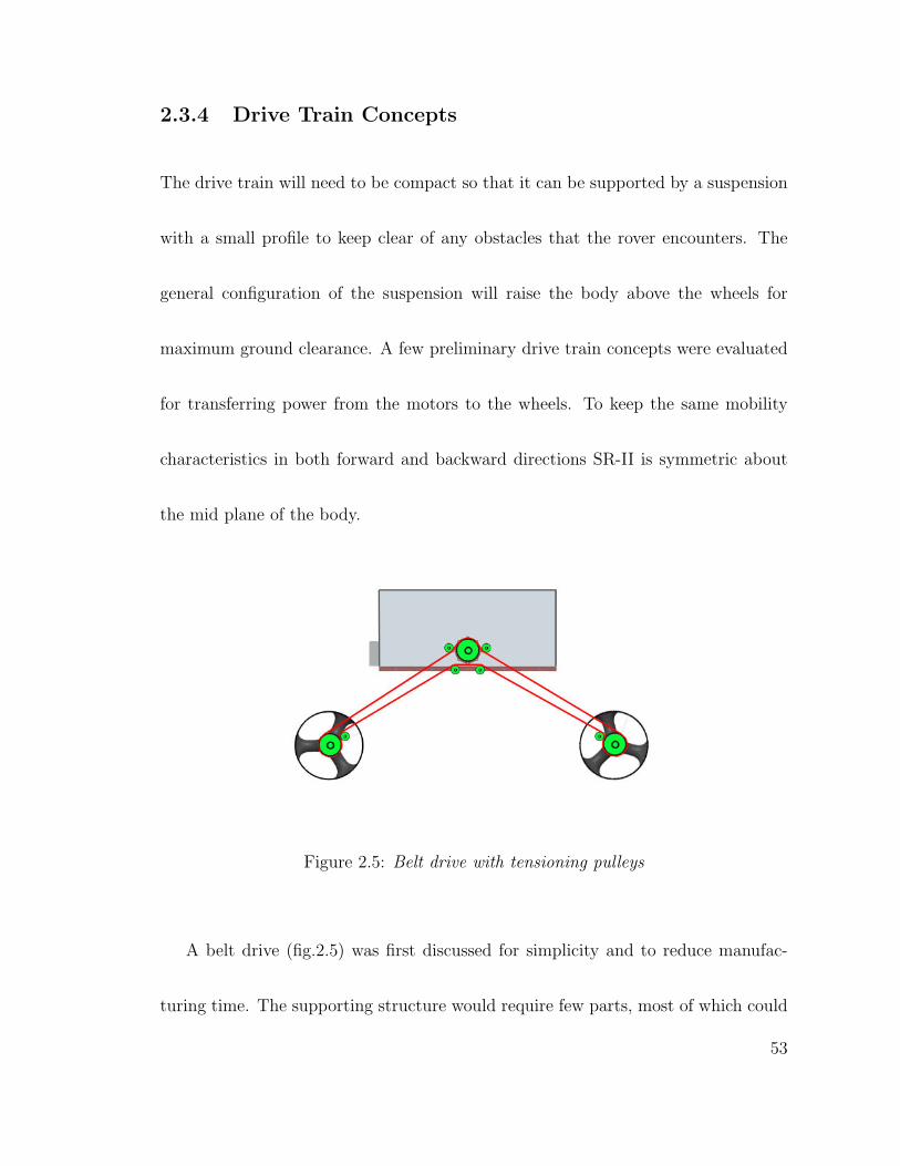
Figure 2.6: Chain and Sprocket drive with idler sprockets
54
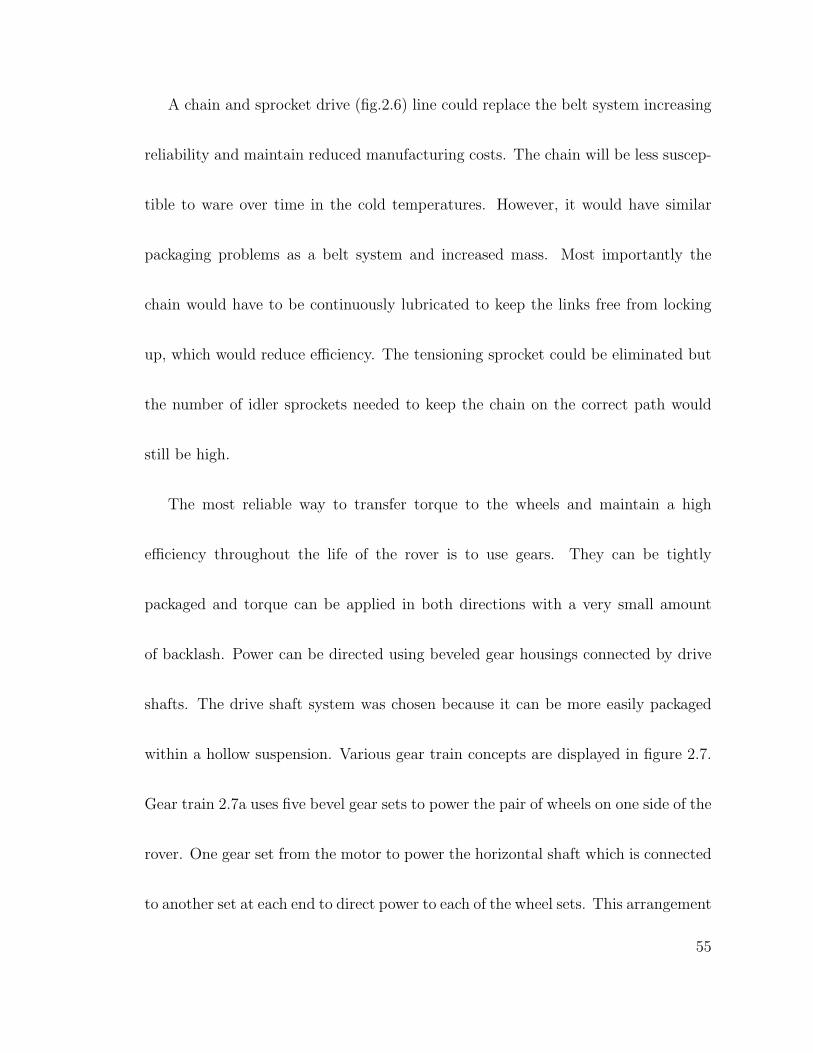
A chain and sprocket drive (fig.2.6) line could replace the belt system increasing
reliability and maintain reduced manufacturing costs. The chain will be less suscep-
tible to ware over time in the cold temperatures. However, it would have similar
packaging problems as a belt system and increased mass. Most importantly the
chain would have to be continuously lubricated to keep the links free from locking
up, which would reduce efficiency. The tensioning sprocket could be eliminated but
the number of idler sprockets needed to keep the chain on the correct path would
still be high.
The most reliable way to transfer torque to the wheels and maintain a high
efficiency throughout the life of the rover is to use gears. They can be tightly
packaged and torque can be applied in both directions with a very small amount
of backlash. Power can be directed using beveled gear housings connected by drive
shafts. The drive shaft system was chosen because it can be more easily packaged
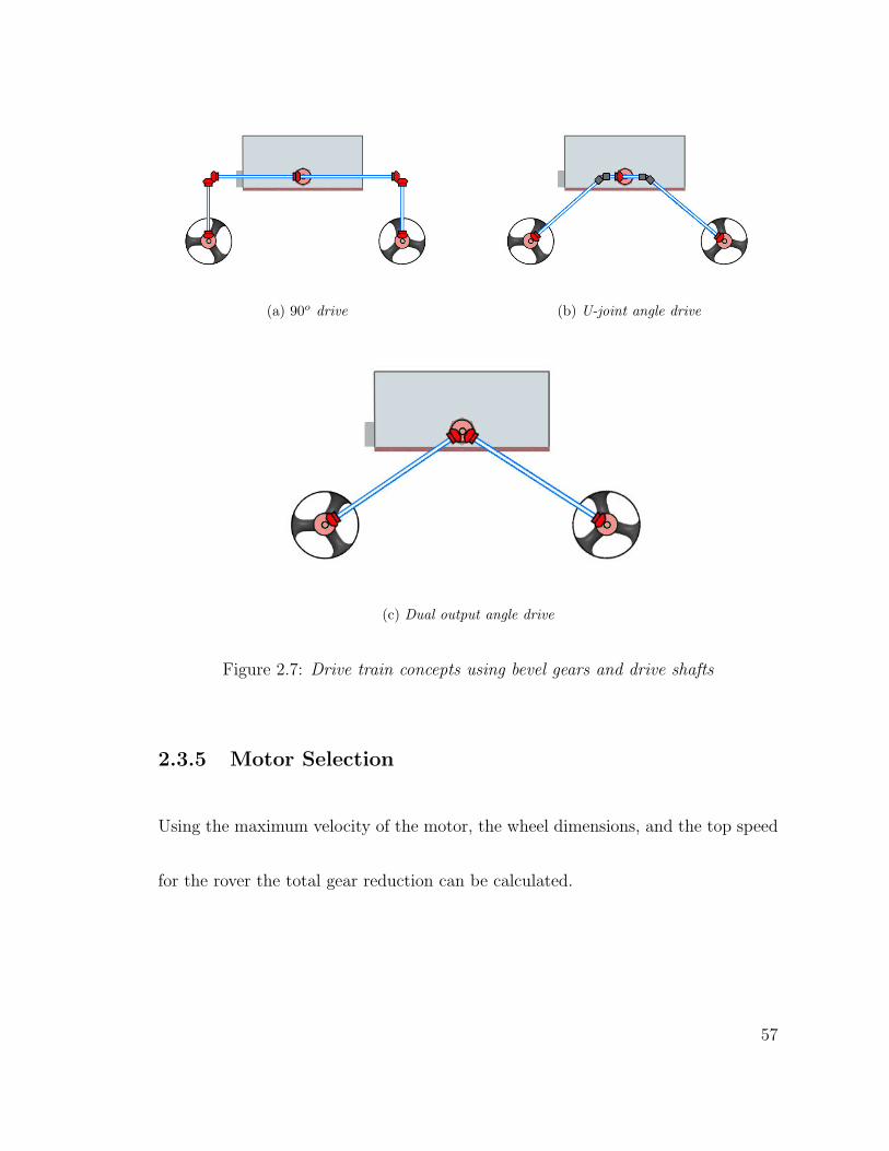
within a hollow suspension. Various gear train concepts are displayed in figure 2.7.
Gear train 2.7a uses five bevel gear sets to power the pair of wheels on one side of the
rover. One gear set from the motor to power the horizontal shaft which is connected
to another set at each end to direct power to each of the wheel sets. This arrangement
55
allows for the largest amount of ground clearance by forcing the suspension above
the wheels almost entirely. It requires a robust suspension to handle the forces on
it when turning potentially increasing mass.
If a drive train structure such as the one in figure 2.7b is used then the two 90o
gear sets can be eliminated and the forces from driving will be directed toward the
mounting point of the body creating a more rigid design. The concept in figure 2.7b
uses the same gear set from the motor to power the much shorter horizontal shaft.
The ends of the shaft are connected to the angled shafts that drive the wheels by
a universal joint. This design can be further simplified by replacing the horizontal
shafts and U-joints with one gear.
SR-II will use the concept in figure 2.7c where the motor is the input into a bevel
gear set with a dual output at the point of attachment to the body for better load
distribution. The angled shafts will power a bevel gear set at the opposite end to
drive the wheels.
56
(a) 90o drive (b) U-joint angle drive
(c) Dual output angle drive
Figure 2.7: Drive train concepts using bevel gears and drive shafts
2.3.5 Motor Selection
Using the maximum velocity of the motor, the wheel dimensions, and the top speed
for the rover the total gear reduction can be calculated.
57
N =2 · π · rw · ωm
νmax
(2.5)
A gear ratio of about 274:1 is needed to achieve a top speed of 20 cms
, where the
rotational velocity of the motor is given by ωm approximately 5000 rpm. There are
three places on the drive train where the ratio can be split. The planetary gear box
on the motor will take up the largest percentage of the reduction because it should
maintain itself better being inside the heated body. The upper bevel gear set that
connects the planetary gear to the angled shafts will have the smallest percentage of
reduction. This is done to keep the torque that is passed by the angled shafts low,
keeping the diameter of the shafts small reducing mass. The final gear reduction
can be done at the wheel with the lower bevel gear set. The final design gear ratio
of 258:1 comes from a planetary gear box with a 43:1 reduction, an upper bevel gear
set of 1.5:1, and a lower bevel gear set of 4:1. Since this ratio is smaller than what is
calculated the rover will have a slightly higher top speed. The required torque from
the motor can be calculated using the torque when climbing over an obstacle.
58
Tm =Tw
N(2.6)
where N is the total gear ratio. The motors will need to produce 30mN ·m of
torque to climb over an obstacle.
Pm = Tm · ωm (2.7)
The power rating for a motor driving the calculated torque requirement is 15.7W
from equation 2.7. This is expected because it is near one half of the 30W input.
Torque is generated from two 12 volt/10.5 watt Faulhaber DC graphite brushed
coreless motors. The coreless design maintains an increased efficiency over a longer
life span because it requires less current than permanent magnet motors for a given
torque output. The motor and planetary gear is purchased as an assembly from
MicroMo Corporation; no modification is needed to use them in the design.
The wattage rating for the motors is lower than the calculated wattage needed
because the rover is not expected to continuously climb obstacles during an entire
kilometer. In the case that it does the speed of the rover will be compromised. The
59
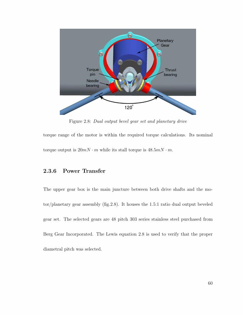
Figure 2.8: Dual output bevel gear set and planetary drive
torque range of the motor is within the required torque calculations. Its nominal
torque output is 20mN ·m while its stall torque is 48.5mN ·m.
2.3.6 Power Transfer
The upper gear box is the main juncture between both drive shafts and the mo-
tor/planetary gear assembly (fig.2.8). It houses the 1.5:1 ratio dual output beveled
gear set. The selected gears are 48 pitch 303 series stainless steel purchased from
Berg Gear Incorporated. The Lewis equation 2.8 is used to verify that the proper
diametral pitch was selected.
60
σb =Wtpd
FY(2.8)
The bending stress in the gear teeth are calculated based on F the face width of
the gear, Wt the tangential load, pd the diametral pitch, and the Lewis form factor
Y (see appendix for calculations). The pinion is secured to the output shaft of the
planetary gear with a cross drilled spring pin. The output gears are placed 120o
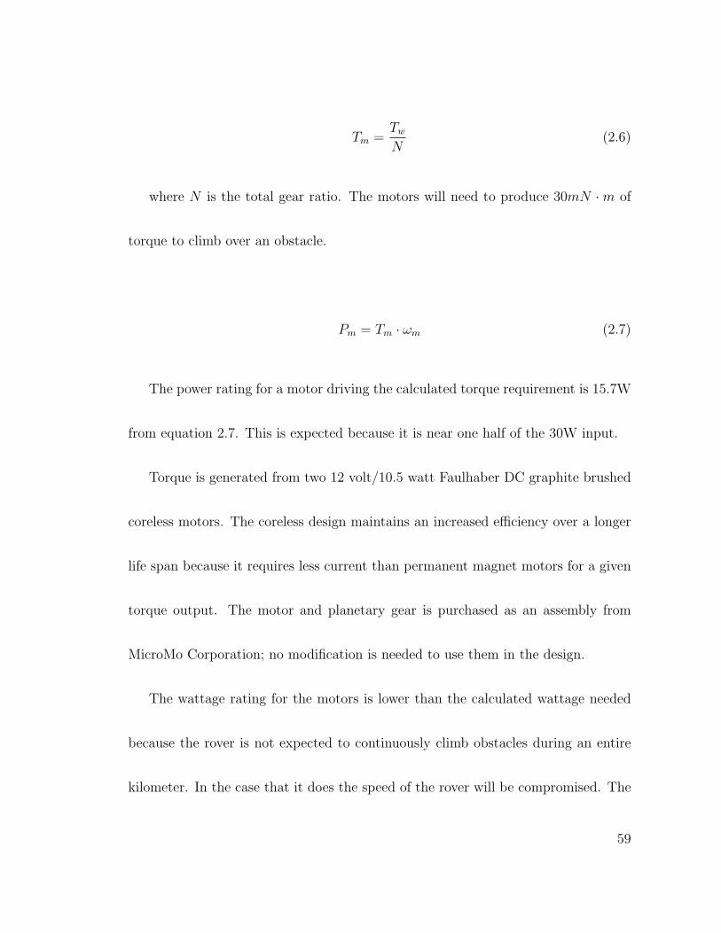
apart as seen in figure 2.8 to keep the lower half of the gears from interfering with
each other. They are connected to 0.25in diameter stainless steel drive shafts that
provide torque to a wheel gear box. The mounting hub on each gear has a groove cut
into the end that mates with a 332
in diameter pin through the drive shaft to provide
torque transfer. The end of the drive shaft is grooved for a retaining ring that keeps
the gear from falling off during assembly. Miniature thrust and needle bearings at
each end of the shaft provide stability in axial and radial directions. A separate
bearing for each loading condition is used to save weight and space. A single ball
bearing capable of reliably handling both loading conditions is too costly.
61
Figure 2.9: Lower bevel gear set and wheel axle
The opposite end of the drive shaft is connected to the 4:1 wheel gear box (fig.2.9).
These gears are 2024-T4 aluminum and hard anodized to increase surface hardness.
Modifications are made to the pinion similar to the gears in the upper gear box to
mate with the drive shaft torque pin. The mating bevel gear is mounted directly
to the wheel axle. The forces acting on the wheel are more efficiently supported
with a larger diameter axle. A 1.5in hole is bored through the center of the gear
to align it coaxially with the axle. It is held in place with five #2-56 threaded
fasteners. The axle is designed to save weight. The mass near the axis of rotation,
which is not needed, is removed as can be seen in figure 2.10. Kaydon X-contact ball
bearings straddle the axle on both ends to support all radial and axial loads. One
62
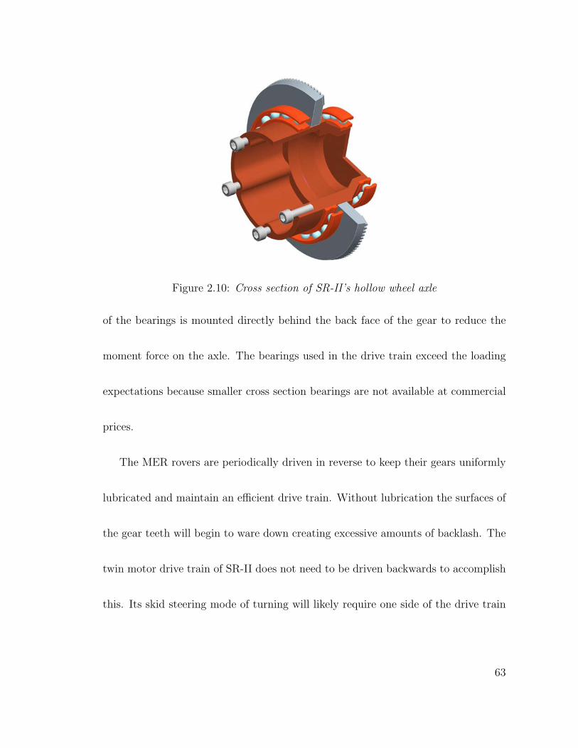
Figure 2.10: Cross section of SR-II’s hollow wheel axle
of the bearings is mounted directly behind the back face of the gear to reduce the
moment force on the axle. The bearings used in the drive train exceed the loading
expectations because smaller cross section bearings are not available at commercial
prices.
The MER rovers are periodically driven in reverse to keep their gears uniformly
lubricated and maintain an efficient drive train. Without lubrication the surfaces of
the gear teeth will begin to ware down creating excessive amounts of backlash. The
twin motor drive train of SR-II does not need to be driven backwards to accomplish
this. Its skid steering mode of turning will likely require one side of the drive train
63
to reverse every time in must make a small radius turn. This will eliminate the need
for having just as many navigation sensors on the front as the rear.
2.4 Suspension
The suspension can be considered the exoskeleton of SR-II. Its primary purpose is
to support the weight of the body and stabilize any components attached to. It is
similar to an exoskeleton because it also supports and protects the drive train inside
its hollow structure. The gear housings for the drive train are integrated at the
joints of the major suspension pieces. Thin-walled structures are used since they are
able to support various loading conditions and remain light weight. The suspension
pieces are designed to wrap around the internal components to reduce the amount
of external area that could cause the rover to get stuck on an obstacle.
2.4.1 Central Differential
The unsteady motion of driving over rough terrain must be buffered by the sus-
pension so the sensors attached to the body can obtain valid readings. This can
be accomplished using springs and dampers or free pivoting joints. Springs and
64
dampers are usually used for higher speed vehicles to absorb the shock loads from
driving over rough terrain. Most rovers use free pivoting joints to maintain even
loading on all wheels. This is acceptable because the top speed of the rover is lower
than the ballistic velocity of the wheel.
V <√
r · g (2.9)
This means that the forward motion of the rover must be less that V for the
wheels with radius r to maintain contact with the ground [49]. SR-II would have to
drive faster than 0.57ms
with 100mm radius wheels on Mars to become unstable.
Traction is maintained by using a passive differential to stabilize the body. The
central differential connects both sides of the suspension to the body and allows
them to rotate freely with respect to each other. This feature is used on all rocky
rovers because it serves two major functions when driving on uneven terrain; it
allows even loading on all of the wheels, and reduces the amount of body pitch by
one half. This increases the stability of the sensors and instruments mounted to the
body. The weight of the components inside the body can create a moment about
65
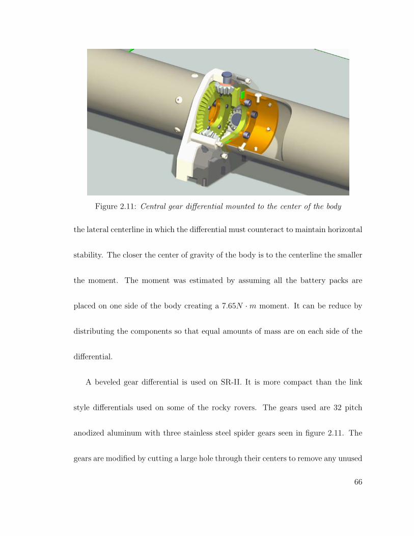
Figure 2.11: Central gear differential mounted to the center of the body
the lateral centerline in which the differential must counteract to maintain horizontal
stability. The closer the center of gravity of the body is to the centerline the smaller
the moment. The moment was estimated by assuming all the battery packs are
placed on one side of the body creating a 7.65N ·m moment. It can be reduce by
distributing the components so that equal amounts of mass are on each side of the
differential.
A beveled gear differential is used on SR-II. It is more compact than the link
style differentials used on some of the rocky rovers. The gears used are 32 pitch
anodized aluminum with three stainless steel spider gears seen in figure 2.11. The
gears are modified by cutting a large hole through their centers to remove any unused
66
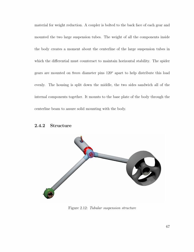
material for weight reduction. A coupler is bolted to the back face of each gear and
mounted the two large suspension tubes. The weight of all the components inside
the body creates a moment about the centerline of the large suspension tubes in
which the differential must counteract to maintain horizontal stability. The spider
gears are mounted on 8mm diameter pins 120o apart to help distribute this load
evenly. The housing is split down the middle, the two sides sandwich all of the
internal components together. It mounts to the base plate of the body through the
centerline beam to assure solid mounting with the body.
2.4.2 Structure
Figure 2.12: Tubular suspension structure
67
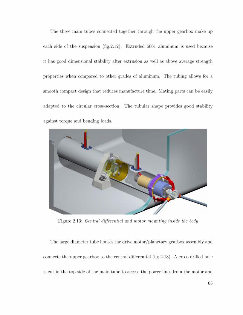
The three main tubes connected together through the upper gearbox make up
each side of the suspension (fig.2.12). Extruded 6061 aluminum is used because
it has good dimensional stability after extrusion as well as above average strength
properties when compared to other grades of aluminum. The tubing allows for a
smooth compact design that reduces manufacture time. Mating parts can be easily
adapted to the circular cross-section. The tubular shape provides good stability
against torque and bending loads.
Figure 2.13: Central differential and motor mounting inside the body
The large diameter tube houses the drive motor/planetary gearbox assembly and
connects the upper gearbox to the central differential (fig.2.13). A cross drilled hole
is cut in the top side of the main tube to access the power lines from the motor and
68
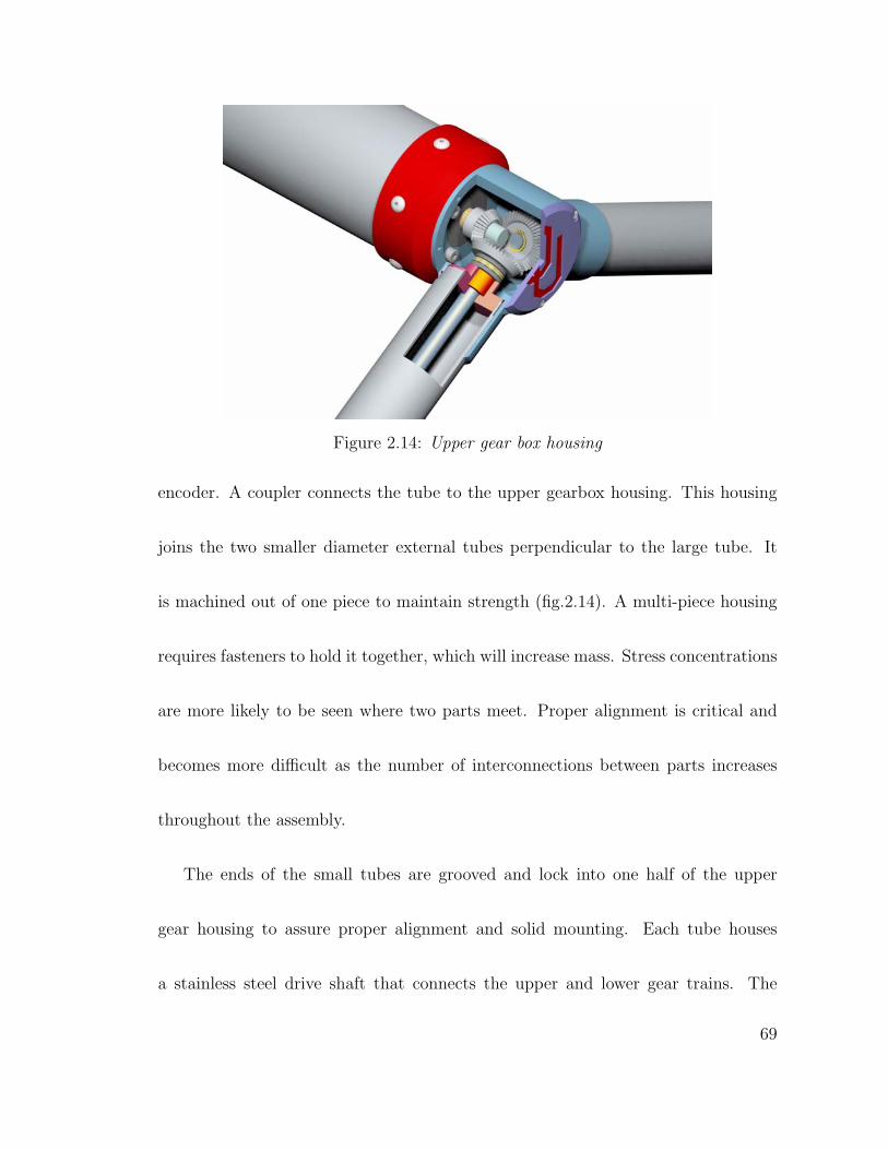
Figure 2.14: Upper gear box housing
encoder. A coupler connects the tube to the upper gearbox housing. This housing
joins the two smaller diameter external tubes perpendicular to the large tube. It
is machined out of one piece to maintain strength (fig.2.14). A multi-piece housing
requires fasteners to hold it together, which will increase mass. Stress concentrations
are more likely to be seen where two parts meet. Proper alignment is critical and
becomes more difficult as the number of interconnections between parts increases
throughout the assembly.
The ends of the small tubes are grooved and lock into one half of the upper
gear housing to assure proper alignment and solid mounting. Each tube houses
a stainless steel drive shaft that connects the upper and lower gear trains. The
69
forces acting on the wheel when the rover drives over an obstacle will create large
bending moments in the tube. Two high stress regions near the connection at the
upper gear housing are evaluated to ensure a safe design. The impact force at the
wheel is assumed equivalent to driving off a 10cm high obstacle. This will create a
moment about all three coordinate axes as well as a compressive and shear load on
the end of the tube. The method of analysis for combined loadings from [16] is used
to calculate the principal stresses. The commercially available 1.125in tube with
0.058in wall thickness tolerates the yield loading condition with a factor of safety
of 1.1(see appendix for calculations). A yield safety factor for mechanical structures
should be kept between 1.0 and 1.4 for prototype space hardware [37].
The lower gear housing is a two piece design split down the vertical plane through
the pinion axis (fig.2.15-2.16). Both sides of the housing are designed to mate with
each other using a tongue-and-groove type fixture. The perimeter of the back housing
plate is recessed while the perimeter of the front plate is extended. This is done to
ensure proper alignment of both pieces when assembled. The housing is held together
with four threaded fasteners. The protrusion at the gear mesh that extends into the
70
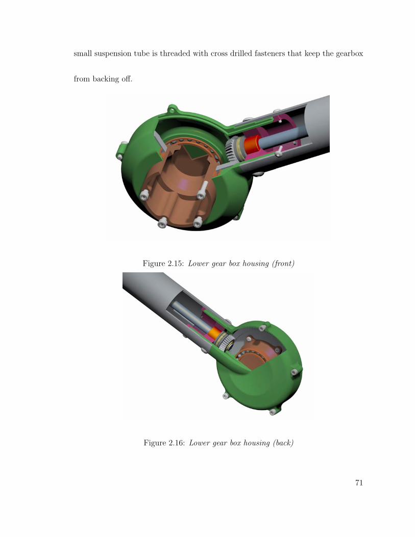
small suspension tube is threaded with cross drilled fasteners that keep the gearbox
from backing off.
Figure 2.15: Lower gear box housing (front)
Figure 2.16: Lower gear box housing (back)
71
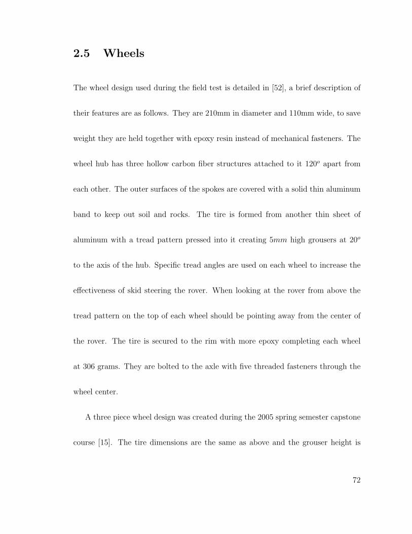
2.5 Wheels
The wheel design used during the field test is detailed in [52], a brief description of
their features are as follows. They are 210mm in diameter and 110mm wide, to save
weight they are held together with epoxy resin instead of mechanical fasteners. The
wheel hub has three hollow carbon fiber structures attached to it 120o apart from
each other. The outer surfaces of the spokes are covered with a solid thin aluminum
band to keep out soil and rocks. The tire is formed from another thin sheet of
aluminum with a tread pattern pressed into it creating 5mm high grousers at 20o
to the axis of the hub. Specific tread angles are used on each wheel to increase the
effectiveness of skid steering the rover. When looking at the rover from above the
tread pattern on the top of each wheel should be pointing away from the center of
the rover. The tire is secured to the rim with more epoxy completing each wheel
at 306 grams. They are bolted to the axle with five threaded fasteners through the
wheel center.
A three piece wheel design was created during the 2005 spring semester capstone
course [15]. The tire dimensions are the same as above and the grouser height is
72
very similar. However, the shape of the tire has been modified. The outer and inner
edges of the tire are chamfered with a 16o angle. The center section is 40mm wide
and does not contain any grousers to increase rolling efficiency. Unlike the carbon
fiber wheels of [52] these wheels are held together with rivets and threaded fasteners,
they mass about 622 grams.
2.6 Electronics
The mechanical makeup of SR-II is the primary focus of this thesis though there are
other components that are needed in a mobile robotic system. The following section
includes a description of the electrical components that allow SR-II to achieve its
goals. These components are specific to what was used during the field test in the
Salton Sea. A PC-104 Plus system is used as the brain of the robot. It is powered
by a commercially available solar panel which also provides energy for the motors,
sensors, and communication, any excess energy from the solar panel is stored in an
array of battery packs. Extra energy can also be pulled from these batteries during
power intensive activities which require more current than what is produced by the
solar panel.
73
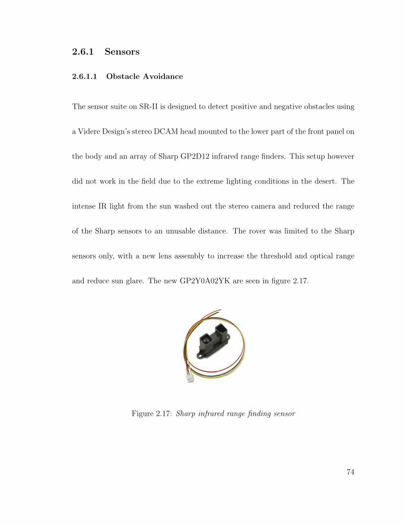
2.6.1 Sensors
2.6.1.1 Obstacle Avoidance
The sensor suite on SR-II is designed to detect positive and negative obstacles using
a Videre Design’s stereo DCAM head mounted to the lower part of the front panel on
the body and an array of Sharp GP2D12 infrared range finders. This setup however
did not work in the field due to the extreme lighting conditions in the desert. The
intense IR light from the sun washed out the stereo camera and reduced the range
of the Sharp sensors to an unusable distance. The rover was limited to the Sharp
sensors only, with a new lens assembly to increase the threshold and optical range
and reduce sun glare. The new GP2Y0A02YK are seen in figure 2.17.
Figure 2.17: Sharp infrared range finding sensor
74
2.6.1.2 Tilt,Roll, and Heading
A Honeywell HMR 3000 magnetic flux gate compass is used to detect heading mea-
surements as well as pitch and roll angles. A serial connection transmits updated
measurements at 15Hz to the control system which decides if the rover is climbing
too steep of a slope or about to roll over. The compass accuracy is ±0.5o.
Electrical current is also measured at various points in the system to ensure safe
operation. The motor current is monitored, in the event of a stalled wheel it is shut
down. The solar panel current is also monitored to ensure that the proper amount
of power is supplied to the rest of the system, if not the system goes into sleep mode
until sufficient sunlight is obtained. A similar feature is also initiated if the battery
voltage becomes too low, the system goes to sleep until the solar panel recharges
them.
2.6.1.3 Odometry
The motors have 64 counts per revolution quadrature encoders to help keep track
of the rover’s position. The gearing reduction allows for 131 counts per centimeter
75
traveled. The rover is driven strait by maintaining an acceptable difference between
the encoder counts from both sides of the drive train.
2.6.2 Power
2.6.2.1 Solar Panel
A Kyocera KC60 glass pane solar panel 0.45m2 is used as SR-II’s main power source.
The panel is the single most massive part of the rover with a mass of 6.79kg. It can
produce 60 watts of energy during peak hours of the day centered on noon. The
computer control system consumed 14 watts on average except when performing
I/O on the hard disk then it would spike to 22 watts. The drive motors pulled 6 to
10 watts on level ground at top speed, but consumed 20-25 watts when turning in
place and would peak out at 45 watts if a wheel was stalled.
2.6.2.2 Batteries
Four battery packs are used to store energy that can be used over night or during
power intensive operations. If the voltage drops below a predefined threshold the
rover would fall into sleep mode until the solar panel recharged them to an acceptable
level. Five D sized cells are wired in series to provide 12 volts for each pack.
76
2.7 Control System
A PC-104 Plus board stack is used for sensor data processing, motor control, and
handling commands from the ground station. All computation is done on a 400
MHz Pentium III processor board with data storage on a hard drive. The operating
system is Red Hat Linux 7.3 and is capable of computing a stereo image depth map a
few times a minute. The CPU board has two serial ports, one to control both motors
through a mini-SSC and another to receive updated readings from the compass. A
single USB port is used to communicate with twin digital cameras mounted on a
removable mast. The I/O IEEE1394 board communicates with the IR sensors, amp
meters, and stereo cameras. A quad-decoder board keeps track of odometer readings
from the two encoders on each of the drive motors. Finally a power supply board
distributes power to the rest of the system and +5 volts to the IR sensors, encoders,
and an additional USB hub which is placed on the front panel for easy access.
77
2.8 Construction
SR-II has been manufactured using the equipment in the AME Machine shop. Most
of the parts were machined in a HAAS CNC VF-8 vertical mill center. This allowed
for complex parts that were designed to be made easily and in a timely manner.
Smaller parts were cut or modified using other manual tools in the shop such as a
mill, lathe, grinding and polishing equipment and welding centers.
Pro Engineer CAD software was used for all of the design work. The rover is
assembled in the CAD environment before any machining is done. Each part that
must be milled in the CNC is assembled in the MFG mode of Pro-E so that cutting
and drilling sequences can be created. The G-Code for the HAAS CNC is processed
from this manufacturing module of Pro-E.
The finished rover is held together with standard sized screws, lock rings, and
pins. The rover can be fully disassembled using a set of hex wrenches, a pair of
external ring pliers, and a small rubber mallet.
78
Chapter 3
Experimental Setup and Procedure
The SR-II rover was put through a series of experiments to evaluate the features
of its design [34, 31]. A field test and a laboratory test were the two primary
evaluations in which the experiments were conducted. During the field test the
rover was autonomously driven across Mars-like terrain using the IR sensors on
board. The lab test drove the rover though a series of experiments to define the real
world limits of the SR-II mobility system. Both of these tests are detailed in the
following sections.
79
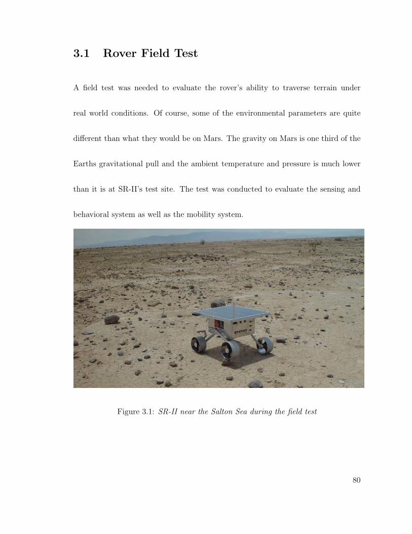
3.1 Rover Field Test
A field test was needed to evaluate the rover’s ability to traverse terrain under
real world conditions. Of course, some of the environmental parameters are quite
different than what they would be on Mars. The gravity on Mars is one third of the
Earths gravitational pull and the ambient temperature and pressure is much lower
than it is at SR-II’s test site. The test was conducted to evaluate the sensing and
behavioral system as well as the mobility system.
Figure 3.1: SR-II near the Salton Sea during the field test
80
3.1.1 Location and Terrain features
The Anza Borrego Desert in Southern California was selected by the sponsor MSSS
(fig.3.1). This region reflects similar geological features that are analogous to the
most easily accessible layered or sedimentary materials on Mars [28]. The topography
is relatively low, with isolated non-traversable terrain elements such as steep slopes,
escarpments, deep channels and a small number of large rocks relative to the scale
of the rover. The absence of meteor impact craters leads to the fact that there
are few large rocks. This configuration of terrain elements is seen on Mars where
layered rock is created by wind and/or lake-water sediments. The Borrego test site
is situated on the western edge of the Salton Sea Lake where similar processes are
taking place [43].
3.1.2 Rover Setup
SR-II can be run under tele-operation or autonomous modes. The tests conducted
in the desert were run under autonomous mode. The control system on SR-II must
first be initiated by specifying a mission that the user at the ground station would
like to run. Each mission has a final destination or goal with intermediate waypoints
81
that the rover must pass through to reach the goal. The waypoints are placed in
predefined locations by the user to set the general path the rover must follow. This
path is used to help guide the rover around known obstacles where their locations
are based on satellite images taken of the area. These images simulate the images
taken during the landing phase of an actual mission. Before egress, the rover can
send these images back to Earth to allow the operators a bird’s-eye view of the
surrounding terrain. The location of each waypoint is stored in rectangular or polar
coordinates, where the initial location of the rover is reset to the origin.
Once the mission begins, the path taken between each waypoint is left up to the
rover. It first tries to drive directly to the next waypoint or goal, however an obstacle
may block the chosen path. The forward facing IR sensors are used to detect the
obstacles location relative to the rover. The control system decides what avoidance
behavior to initiate based on what specific sensor group detects the obstacle. For
example, if the right cluster detects a rock the rover backs up for a few seconds, then
rotates to the left (counter-clockwise) and attempts to move again. This sequence is
repeated until the right sensor does not detect any hazards. The rover recalculates
the path toward its destination based on its new location after it has gone around
82
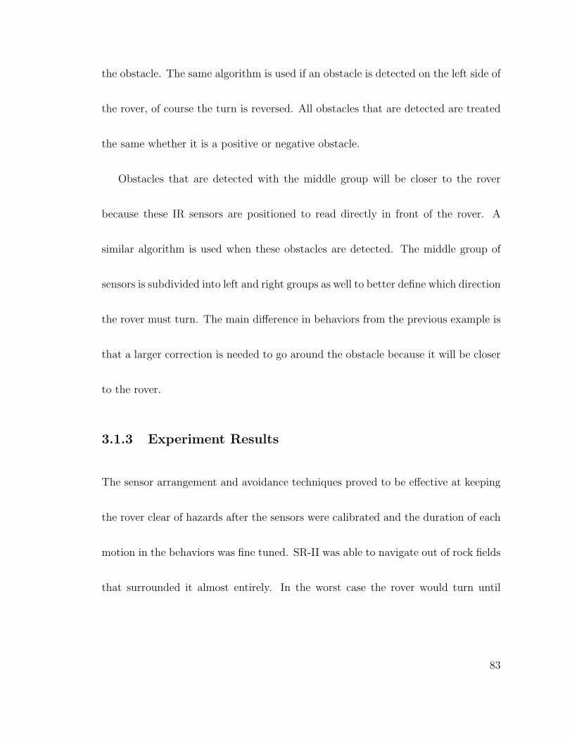
the obstacle. The same algorithm is used if an obstacle is detected on the left side of
the rover, of course the turn is reversed. All obstacles that are detected are treated
the same whether it is a positive or negative obstacle.
Obstacles that are detected with the middle group will be closer to the rover
because these IR sensors are positioned to read directly in front of the rover. A
similar algorithm is used when these obstacles are detected. The middle group of
sensors is subdivided into left and right groups as well to better define which direction
the rover must turn. The main difference in behaviors from the previous example is
that a larger correction is needed to go around the obstacle because it will be closer
to the rover.
3.1.3 Experiment Results
The sensor arrangement and avoidance techniques proved to be effective at keeping
the rover clear of hazards after the sensors were calibrated and the duration of each
motion in the behaviors was fine tuned. SR-II was able to navigate out of rock fields
that surrounded it almost entirely. In the worst case the rover would turn until
83
it was forced to backtrack the way it came, displaying its ability to avoid complex
obstacles.
Before the main run of SR-II during the field test, a closed loop course was driven
to determine the average dead-reckoning error. The course was 200m or more and it
was found that the rover would finish within a 2% error of the distance traveled from
the start position. The course included rugged terrain with slopes up to 15o. The
heading from the compass is accurate enough to make driving the rover using dead-
reckoning navigation reliable enough to achieve specific goals. The relatively small
amount of error confirms that the wheel design of SR-II is capable of minimizing
slippage.
At 12:30pm on a June afternoon in 2002 SR-II began its final test across the
desert terrain. The rover was given waypoints to a goal with an estimated path
length of 1.3km. On average the waypoints were 122m apart with the closest about
25m and the longest was just less than 200m. The path was selected to have the rover
navigate around major geologic features in the area based on satellite images. For
the next five hours the rover ran completely autonomously except for two instances,
one of which was configuring the rover to take “science” images. The other instance
84
was due to thermal failure of the epoxy that held the rim of the wheel together
(fig.3.2). Within a few minutes the wheel was fastened together using rivets and
zip-ties so the remaining part of the mission could be completed. It should be noted
that the initial design of the wheel is for much cooler temperatures and was not
expected to perform as well on the scorching (55Co) terrain in the desert.
Figure 3.2: SR-II thermal delamination of the wheel
The rovers physical behavior when driving is best described in [34]. To observers
the immediate path of the rover appeared inefficient when driving between way-
points especially on a slope. The control system would turn the rover away from its
destination until an acceptable slope was reached, then turn back toward the next
waypoint. This behavior would continue to happen causing the rovers path to look
like a series of switchbacks, similar to a trail on a mountain side. SR-II appeared to
have problems gaining ground. However, if the rover was not followed as intensely
85
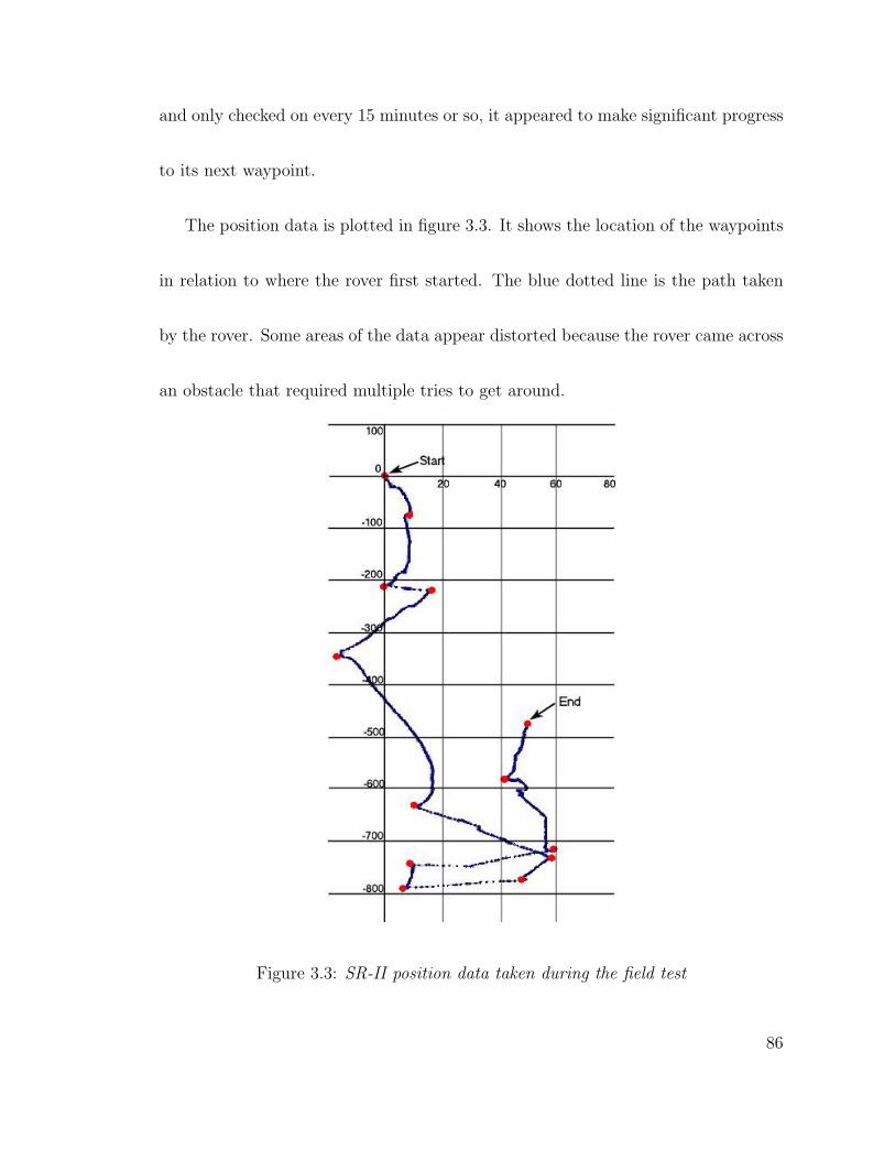
and only checked on every 15 minutes or so, it appeared to make significant progress
to its next waypoint.
The position data is plotted in figure 3.3. It shows the location of the waypoints
in relation to where the rover first started. The blue dotted line is the path taken
by the rover. Some areas of the data appear distorted because the rover came across
an obstacle that required multiple tries to get around.
Figure 3.3: SR-II position data taken during the field test
86
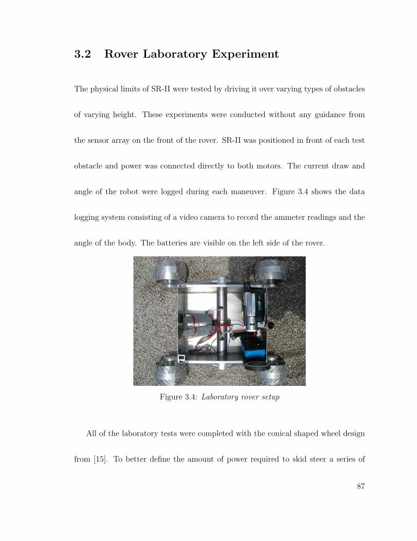
3.2 Rover Laboratory Experiment
The physical limits of SR-II were tested by driving it over varying types of obstacles
of varying height. These experiments were conducted without any guidance from
the sensor array on the front of the rover. SR-II was positioned in front of each test
obstacle and power was connected directly to both motors. The current draw and
angle of the robot were logged during each maneuver. Figure 3.4 shows the data
logging system consisting of a video camera to record the ammeter readings and the
angle of the body. The batteries are visible on the left side of the rover.
Figure 3.4: Laboratory rover setup
All of the laboratory tests were completed with the conical shaped wheel design
from [15]. To better define the amount of power required to skid steer a series of
87
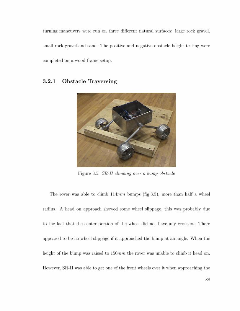
turning maneuvers were run on three different natural surfaces: large rock gravel,
small rock gravel and sand. The positive and negative obstacle height testing were
completed on a wood frame setup.
3.2.1 Obstacle Traversing
Figure 3.5: SR-II climbing over a bump obstacle
The rover was able to climb 114mm bumps (fig.3.5), more than half a wheel
radius. A head on approach showed some wheel slippage, this was probably due
to the fact that the center portion of the wheel did not have any grousers. There
appeared to be no wheel slippage if it approached the bump at an angle. When the
height of the bump was raised to 150mm the rover was unable to climb it head on.
However, SR-II was able to get one of the front wheels over it when approaching the
88
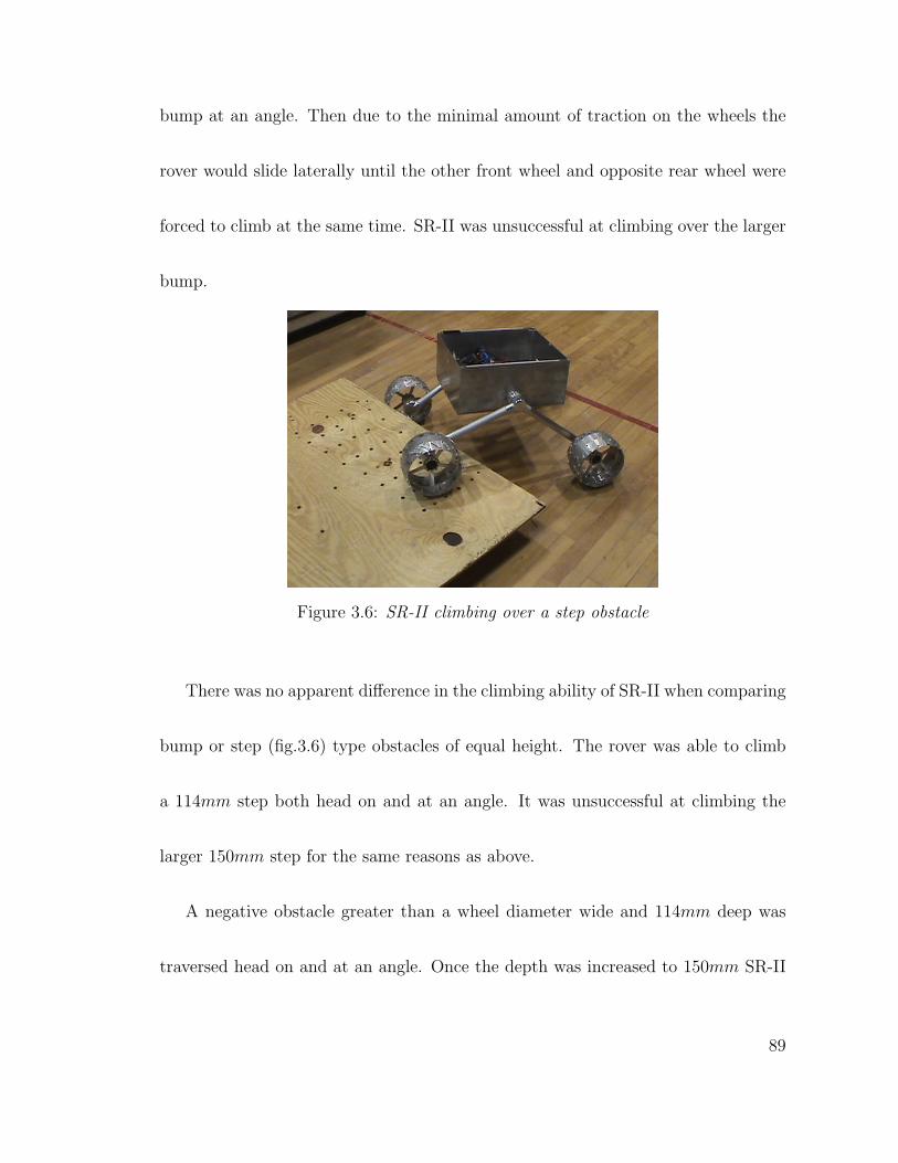
bump at an angle. Then due to the minimal amount of traction on the wheels the
rover would slide laterally until the other front wheel and opposite rear wheel were
forced to climb at the same time. SR-II was unsuccessful at climbing over the larger
bump.
Figure 3.6: SR-II climbing over a step obstacle
There was no apparent difference in the climbing ability of SR-II when comparing
bump or step (fig.3.6) type obstacles of equal height. The rover was able to climb
a 114mm step both head on and at an angle. It was unsuccessful at climbing the
larger 150mm step for the same reasons as above.
A negative obstacle greater than a wheel diameter wide and 114mm deep was
traversed head on and at an angle. Once the depth was increased to 150mm SR-II
89
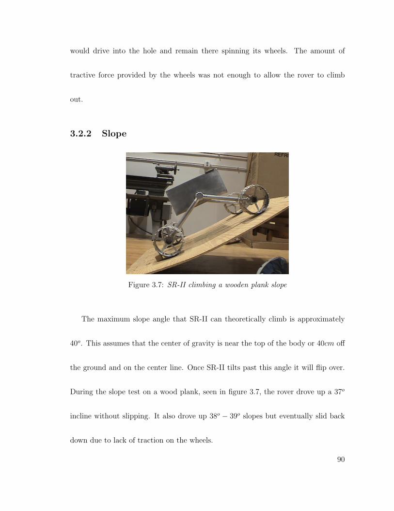
would drive into the hole and remain there spinning its wheels. The amount of
tractive force provided by the wheels was not enough to allow the rover to climb
out.
3.2.2 Slope
Figure 3.7: SR-II climbing a wooden plank slope
The maximum slope angle that SR-II can theoretically climb is approximately
40o. This assumes that the center of gravity is near the top of the body or 40cm off
the ground and on the center line. Once SR-II tilts past this angle it will flip over.
During the slope test on a wood plank, seen in figure 3.7, the rover drove up a 37o
incline without slipping. It also drove up 38o − 39o slopes but eventually slid back
down due to lack of traction on the wheels.
90
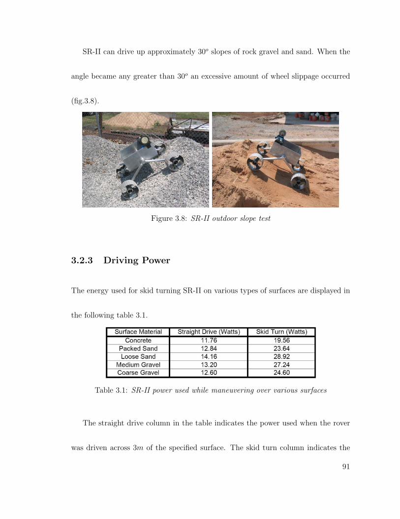
SR-II can drive up approximately 30o slopes of rock gravel and sand. When the
angle became any greater than 30o an excessive amount of wheel slippage occurred
(fig.3.8).
Figure 3.8: SR-II outdoor slope test
3.2.3 Driving Power
The energy used for skid turning SR-II on various types of surfaces are displayed in
the following table 3.1.
Table 3.1: SR-II power used while maneuvering over various surfaces
The straight drive column in the table indicates the power used when the rover
was driven across 3m of the specified surface. The skid turn column indicates the
91
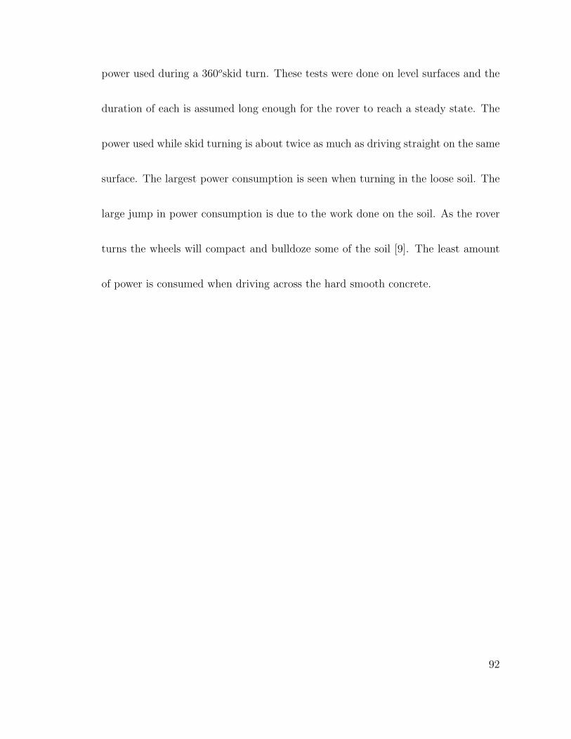
power used during a 360oskid turn. These tests were done on level surfaces and the
duration of each is assumed long enough for the rover to reach a steady state. The
power used while skid turning is about twice as much as driving straight on the same
surface. The largest power consumption is seen when turning in the loose soil. The
large jump in power consumption is due to the work done on the soil. As the rover
turns the wheels will compact and bulldoze some of the soil [9]. The least amount
of power is consumed when driving across the hard smooth concrete.
92
Chapter 4
Results and Lessons Learned
The SR-II rover has the mobility and navigation capabilities to be used for a Mars
exploration mission. The results from the field test experiments present more evi-
dence that the current rover mobility systems used for space exploration are more
complex than is required. Previous works display similar findings, that a rover with
a reduced number of wheels, fewer than six, can still maintain a high degree of
mobility [25] and it can be driven autonomously for tens of kilometers [48].
The twin motor drive train design of SR-II allowed the rover to traverse between
waypoints using the minimal amount of power when driving straight. The skid
steering mode of turning is a more power consuming process than a rocker bogie
suspension of similar scale. However, during long traverses in-between waypoints,
93
SR-II spent most of the time driving straight. The position data in figure 3.3 displays
a slight error in the control system that was discovered after the test. The rover
was not fully correcting itself if it began driving off course. It turned only enough
to bring its heading back to the edge of the steering threshold. This can be seen in
the data as long arcs that eventually curve into the next waypoint.
SR-II was able to achieve hundreds of meters of progress toward its goal per hour.
This is thousands of times faster than Sojourner was allowed to traverse during the
pathfinder mission. It is about five times faster than the MER rover’s furthest single
day traverse [26]. Although, SR-II did not carry out any science during its mission,
this is irrelevant when comparing the mobility and control characteristics of these
systems. While moving, the science instruments are turned off therefore do not
consume power.
SR-II is a fully self contained rover, all of the power used by the mobility, com-
munication, navigation, and control systems came from the 60W solar panel on top
of the rover. On average the drive train used 10 to 12 watts on level ground driving
straight and 18 to 28 watts when turning. More work is done on the soil when skid
steering which is the cause for this increase in power consumption.
94
The final mass of SR-II, including the over weight solar panel, is 22.07kg of which
5.73kg is the mass of the suspension, body and drive train including motors. The
suspension is designed to hold 30kg of mass. This enables the rover to carry about
8kg of science instruments, about 26% of the allotted mass. Sojourner carried 1.3kg
of science equipment, about 12% of the total rover mass flown to Mars. The Mars
exploration rovers carried about 5.5kg of science equipment, 3% of the total rover
mass [51]. The MER rovers were required to carry communications equipment pow-
erful enough to talk directly to Earth, unlike Sojourner. However, future missions
to Mars will not have to carry such massive pieces of equipment because of the Mars
Telecommunications Orbiter which is scheduled to launch in 2009.
A limiting factor of the SR-II mobility design comes from the lack of wheel trac-
tion when climbing obstacles. A more compliant wheel design would be advantageous
in many ways. It would reduce the impact forces on the suspension caused when
driving off obstacles. Also, a wheel that would provide more tractive force than the
current design could bring the mobility characteristics of SR-II up to the level of the
rocker bogie. A more detailed analysis of the angled approach toward an obstacle
needs to be done in order to better define the physical limits of SR-II. A possible
95

increase in mobility may come from modifying the control system behaviors while
traversing an obstacle. Traction forces may be maximized if the control system is
designed to reduce the amount of wheel skidding.
96
Bibliography
[1] Colin M. Angle and Rodney A. Brooks. Small planetary rovers. In International
Workshop on Intelligent Robots and Systems IROS’90. IEEE, April 27, 1990.
[2] Dimitrios Apostolopoulos and John Bares. Locomotion configuration of a ro-
bust rappelling robot. In Proceedings of the 1995 IEEE/RSJ International
Conference on Intelligent Robots and Systems, Human Robot Interaction and
Cooperative Robots (IROS ’95), volume 3, pages 280–284. CMU, August 1995.
[3] Bill Arnett. Mars, February 4 2005. URL http://www.nineplanets.org/
mars.html.
[4] Mike Ayers. Silica aerogels, April 2004. URL http://eande.lbl.gov/ECS/
aerogels/satoc.htm.
[5] Deepak Bapna, Eric Rollins, John Murphy, Mark Maimone, William Red L.
Whittaker, and David Wettergreen. The atacama desert trek: Outcomes. In
Proceedings of ICRA 1998, volume 1, pages 597–604, May 1998.
[6] John Bares and David Wettergreen. Dante II: Technical description, results
and lessons learned. International Journal of Robotics Research, 18(7):621–649,
July 1999.
[7] John Bares, Martial Hebert, Takeo Kanade, Eric Krotkov, Tom Mitchell, Reid
Simmons, and William Red L. Whittaker. Ambler: An autonomous rover for
planetary exploration. IEEE Computer, 22(6):18–26, June 1989.
[8] John E. Bares and William L. Whittaker. Walking robot with a circular gait.
In Proceedings of the 1990 IEEE/RSJ International Conference on Intelligent
Robots and Systems, Towards a New Frontier of Applications (IROS ’90), pages
809–816. IROS, July 1990.
97
[9] M. G. Becker. Theory of Land Locomotion- the Mechanics of Vehicle Mobility.
University of Michigan Press, Ann Arbor, MI, 1956.
[10] Donald Bickler. Roving over mars. mechanical engineering, pages 1–9, April
1998.
[11] Donald B. Bickler. The new family of jpl planetary surface vehicles. In Missions,
Technologies and Design of Planetary Mobile Vehicles, pages 301–306, Toulouse,
France, September 1992. CNES.
[12] Rodney A. Brooks and Anita M. Flynn. Fast, cheap and out of control: A robot
invasion of the solar system. Journal of the British Interplanetary Society, 42:
478–485, 1989.
[13] Andrew Chaikin. The other moon landings: A soviet triumph in the shadow of
apollo. Air and Space, pages 33–37, February/March 2004.
[14] P. R. Christensen. The spacial distribution of rocks on mars. In Proceedings in
ICARUS, pages 217–238, 1986.
[15] Peter Duggan, Jonas Houchin, Oren Lever, James Miller, and Orin Miller. AME
4553: Solar rover 2 (SR2) efficient wheel. Final report, 2005.
[16] James M. Gere and Stephen P.Timoshenko. Mechanics of Materials. PWS
publishing, Boston, fourth edition, 1997.
[17] M. P. Golombek, J. R. Matijevic, E. N. DiMaggio, and R. D. Schroeder. Rock
size-frequency distributions at the mars exploration rover landing site: impact
hazard and accessibility. In Proceedings of Lunar and Planetary Science 2003,
2003.
[18] A. F. C. Haldemann and M. P. Golombek. Mars pathfinder near-field rock
disribution re-evaluation. Lunar and Planetar Science, pages 2029–2030, 2003.
[19] S. Hayati. The rocky 7 rover: A mars sciencecraft prototype, 1997. URL
citeseer.ist.psu.edu/hayati97rocky.html.
98
[20] Tatsuzo Ishida, Yoshihiro Kuroki, and Jinichi Yamaguchi. Mechanical system
of a small biped entertainment robot. In Intl. Conference on Intelligent Robots
and Systems, Las Vegas, Nevada, October 2003. IEEE/RSJ.
[21] Michael R. Johnson. Mars science laboratory: Long life systems,
2005. URL http://marstech.jpl.nasa.gov/content/detail.cfm?Sect=
MTP\&Cat=\\focused\&subCat=MSL\&subSubCat=LLS\&TaskID=788.
[22] Mars Working Group JPL. Mars rover sample return mission science objec-
tives document, February 1989. URL http://www.marsinstitute.info/rd/
faculty/dportree/rtr/rs17.html.
[23] A.L. Kemurdjian, V.V. Gromov, V. Kucherenko, V.K.Mishkinyuk, and P.S. So-
logub. Small marsokhod configuration. In International Conference on Robotics
and Automation, pages 165–168, Nice, France, May 1992. IEEE.
[24] Eric Krotkov, John Bares, Takeo Kanade, Tom Mitchell, Reid Simmons, and
William Red L. Whittaker. Ambler: a six-legged planetary rover. In Fifth
International Conference on Advanced Robotics, 1991, Robots in Unstructured
Environments (ICAR ’91), pages 717–722. ICAR, June 1991.
[25] Y. Kuroda, Koji Kondo, Kazuaki Nakamura, Yashuharu Kunii, and Takashi
Kubota. Low power mobility system for micro planetary rover micro5. In
Proc. of the 5th International Symposium on Artificial Intelligence, Robotics
and Automation in Space (i-SAIRAS’99), pages pp.77–82, 1999.
[26] NASA Jet Propulsion Lab. Mars exploration rover mission, June 2005. URL
http://marsrovers.jpl.nasa.gov/home/.
[27] Andrew J. LePage. Ahead of their time: The soviet lunar program of the
seventies part. THE ELECTRONIC JOURNAL OF THE ASTRONOMICAL
SOCIETY OF THE ATLANTIC, 7(1), January 1996. URL ftp://ftp.seds.
org/pub/info/newsletters/ejasa/jasa9601.txt.
[28] M. C. Malin and K. S. Edgett. Mars global surveyor mars orbiter camera:
Interplanetary cruise through primary mission. J. Geophys. Res., 106 (E10):
2342923570, 2001.
99
[29] J. Matijevic. Mars pathfinder microrover - implementing a low cost planetary
mission experiment. URL citeseer.ist.psu.edu/12063.html.
[30] L. Matthies. Mars microrover navigation: Performance evaluation and enhance-
ment. In Autonomous Robots, Special Issue on Autonomous Vehicles for Plan-
etary Exploration, pages 2(4):291–311, 1995. URL citeseer.ist.psu.edu/
article/matthies95mars.html.
[31] D. P. Miller, T. Hunt, M. Roman, S. Swindell, L. Tan, and A. Winterholler.
Experiments with a long-range planetary rover. In Proceedings of the The 7th
International Symposium on Artificial Intelligence, Robotics and Automation
in Space, Nara, Japan, May 2003. ISAS, NAL, NASDA.
[32] David P. Miller. Personal conversation, 2005.
[33] David P. Miller, Tim S. Hunt, and Matt J. Roman. Experiments and analysis
of the role of solar power in limiting mars rover range. In Proceedings in IROS,
Las Vegas, NV, 2003.
[34] David P. Miller, Li Tan, and Scott Swindell. Simplified navigation and traverse
planning for a long-range planetary rover. In Proceedings of the International
Conference on Robotics and Automation, Taipei, Taiwan, May 2003. ICRA.
[35] Andrew Mishkin. Sojourner: An insider’s view of the Mars Pathfinder Mission.
Berkley books, 2003.
[36] E. Z. Moore, D. Campbell, F. Grimminger, and M. Buehler. Reliable stair
climbing in the simple hexapod ’RHex’. In Conf. On Robotics and Automation
(ICRA), volume 7, pages 2222–2227. IEEE, May 2002.
[37] Daniel R. Mulville. Structural design and test factors of safety for spaceflight
hardware. Technical Report NASA-STD-5001, NASA, June 21 1996.
[38] NASA National Space Science Data Center. Luna 17/lunokhod, 2005. URL
http://nssdc.gsfc.nasa.gov/database/MasterCatalog?sc=1970-095A.
[39] NASA National Space Science Data Center. Luna 21/lunokhod2, 2005. URL
http://nssdc.gsfc.nasa.gov/database/MasterCatalog?sc=1973-001A.
100
[40] Helsinki University of Technology. Wheeled chassis JRover for the planetary
rovers, 1996. URL http://private.peterlink.ru/rcl/j-rover2.htm.
[41] Yusuke Ota, Kan Yoneda, Yusuke Muramatsu, and Shigeo Hirose. Development
of walking and task performing robot with bipedal configuration. In Interna-
tional Conference of Intelligent Robots and Systems, Maui, Hawaii, October 29
2001. IEEE.
[42] Roger D. Quinn, Gabriel M. Nelson, Richard J. Bachmann, Daniel A. Kingsley,
John Offi, and Roy E. Ritzmann. Insect designs for improved robot mobility.
In Berns and Dillmann, editors, Int. Conf. On Climbing and Walking Robots,
number 4, pages 69–76, 2001.
[43] Mike Ravine. Mars scout class rover proposal, July 2005. Personal e-mail.
[44] P. S. Schenker, E. T. Baumgartner, P. G. Backes, H. Aghazarian, L.I. Dorsky,
J. S. Norris, T. L. Huntsberger, Y. Cheng, A. Trebi-Ollennu, M. S. Garret,
B. A. Kennedy, A. J. Ganino, R. E. Arvidson, and S. W. Squyres. FIDO: A
field integrated design and operations rover for mars surface exploration. In
Proceedings in i-SAIRAS, Montreal Canada, June 2001.
[45] Reid Simmons, Eric Krotkov, Lonnie Chrisman, Fabio Cozman, Richard Good-
win, Martial Hebert, Lalitesh Katragadda, Sven Koenig, Gita Kishnaswamy,
Yoshikazu Shinoda, and William Whittaker. Experience with rover navigation
for lunar-like terrains. In Proceedings of the 1995 Conference on Intelligent
Robots and Systems (IROS ’95), pages pp. 441 – 446. IEEE, 1995.
[46] P. H. Smith and M. Lemmon. Opacity of the martian atmosphere measured by
the imager for mars pathfinder. J. Geophys. Res, pages 104:8975–8985, 1999.
[47] C. Stoker, N. Cabrol, T. Roush, V. Gulick, G. Hovde, J. Moersch, and the Mar-
sokhod Rover Team. 1999 MARSOKHOD FIELD EXPERIMENT: A SIMU-
LATION OF a MARS ROVER SCIENCE MISSION. In Lunar and Planetary
Science. NASA Ames Research Center, 1999.
[48] William Red Whittaker. Atacama desert trek: A planetary analog field exper-
iment. URL citeseer.ist.psu.edu/280109.html.
101
[49] Brian Wilcox. Robotic vehicle system engineering. Technical Presentation,
April 2003.
[50] Brian Wilcox, Larry Matthies, Donald Gennery, Brian Cooper, Tam Nguyen,
Todd Litwin, Andrew Mishkin, and Henry Stone. Robotic vehicles for planetary
exploration. In International Conference on Robotics and Automation, pages
175–180, Nice, France, May 1992. IEEE.
[51] G.R. Wilson, J.M. Andringa, L.W. Beegle, J.F. Jordan, G.S. Mungus, D.A.
Muliere, J. Vozoff, and T.J. Wilson. Mars surface mobility: Comparison of
past, present and future rover systems. In Lunar and Planetary Science XXXVI,
pages 2219–2220. Jet Propulsion Laboratory, 2005.
[52] Alois Winterholler. Development, design and verification of different wheel con-
cepts for nasa’s field integrated design and operations rover. Master’s thesis,
Fachhochschule Augsburg, Hochschule fur Technik Wirtschaft Gestaltung, Uni-
versity of Applied Sciences, November 2002.
102
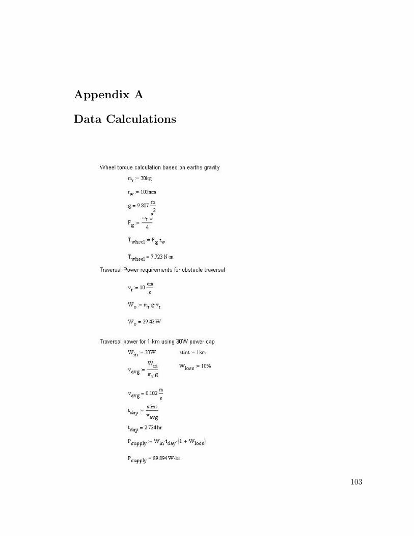
Appendix A
Data Calculations
103
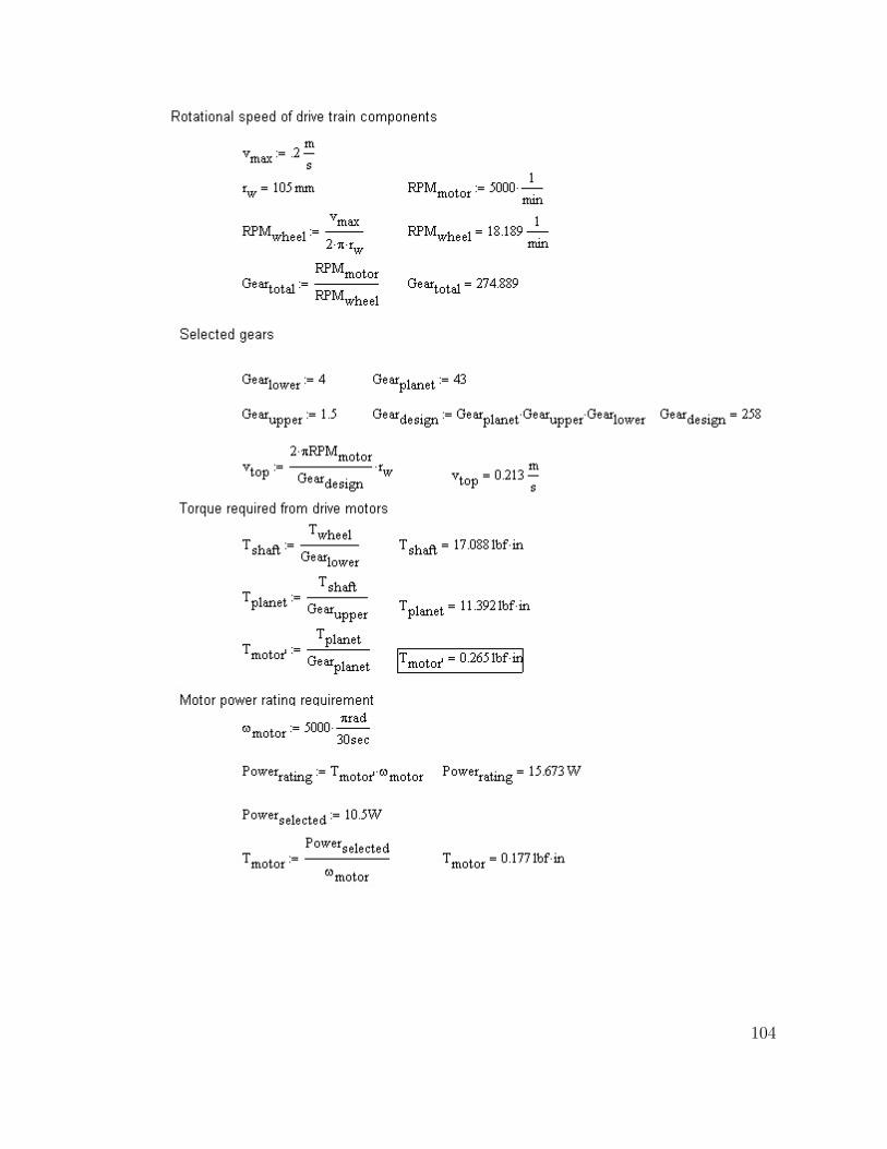
104
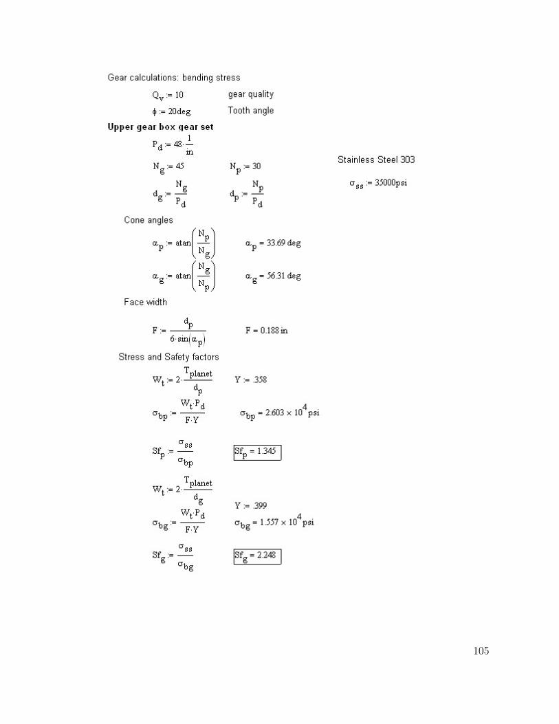
105
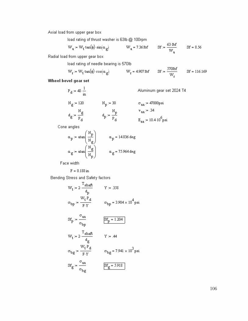
106
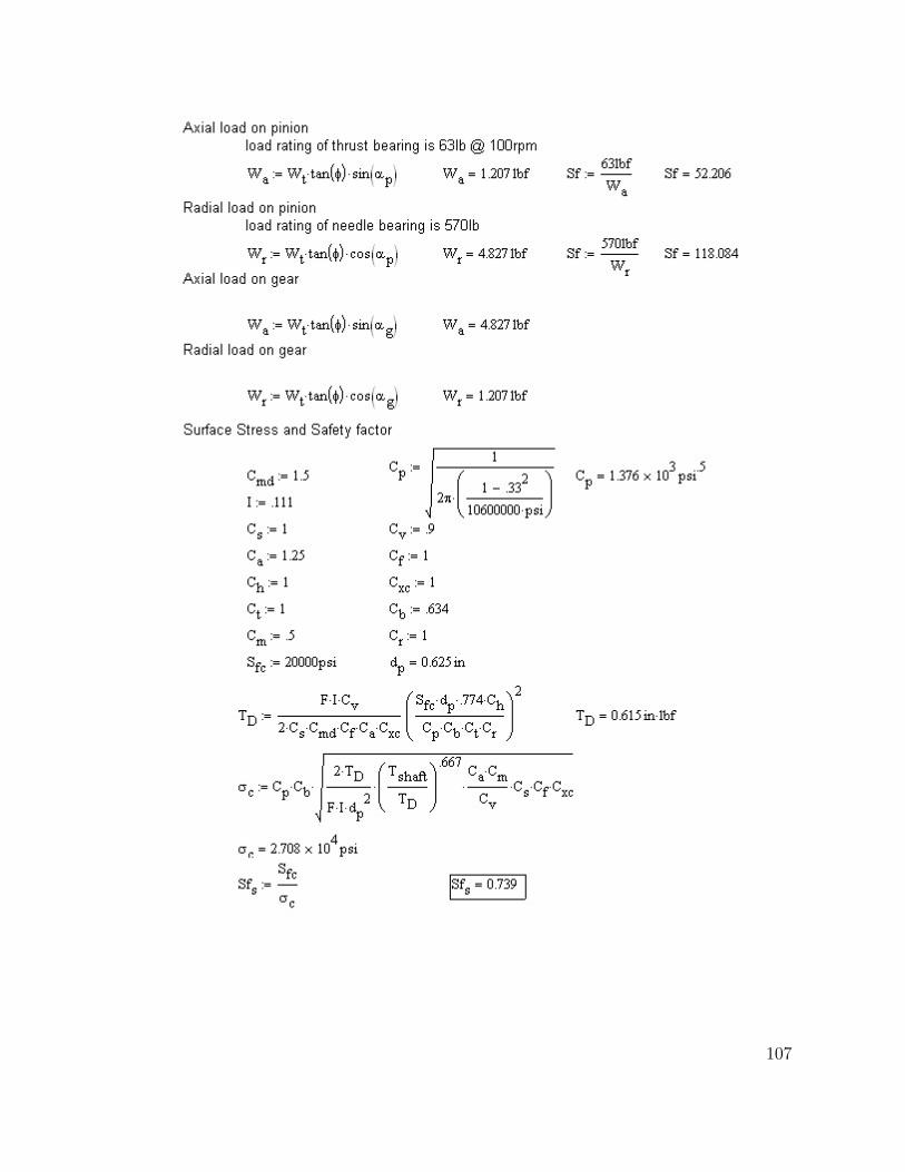
107
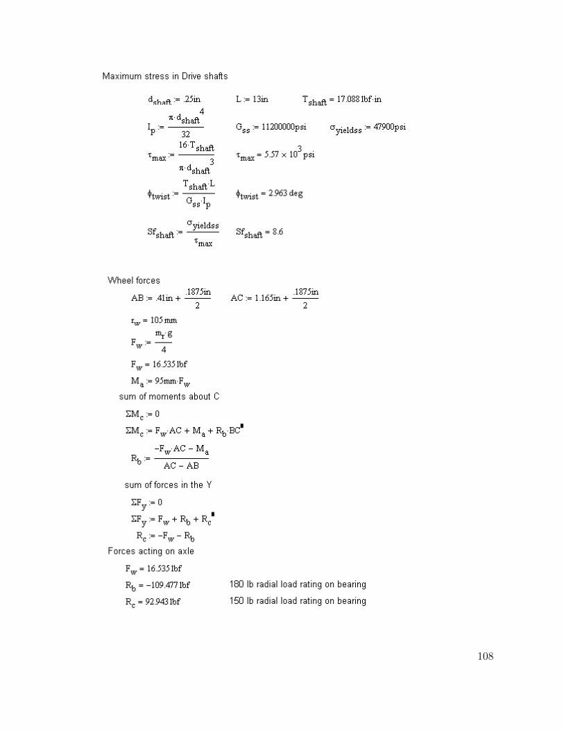
108
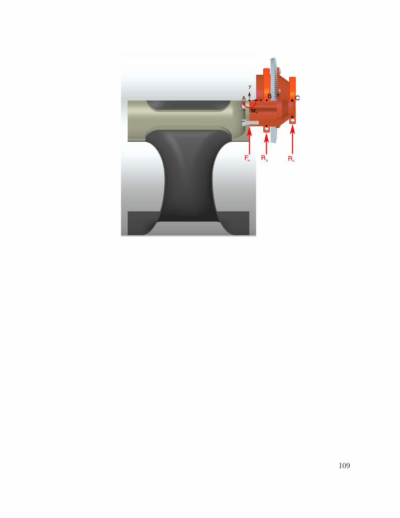
109
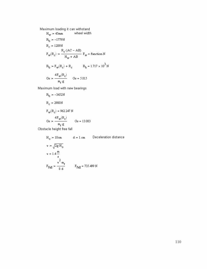
110
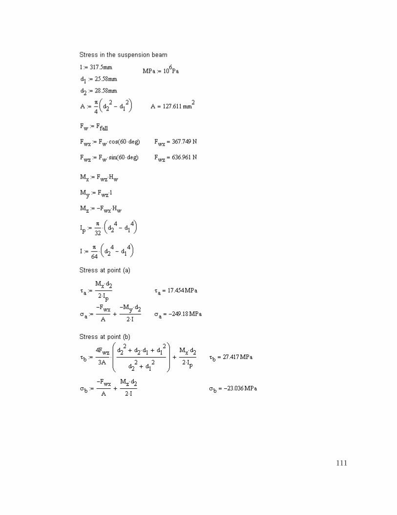
111
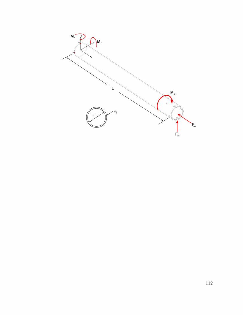
112
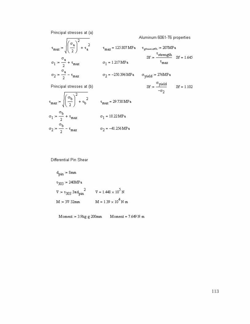
113
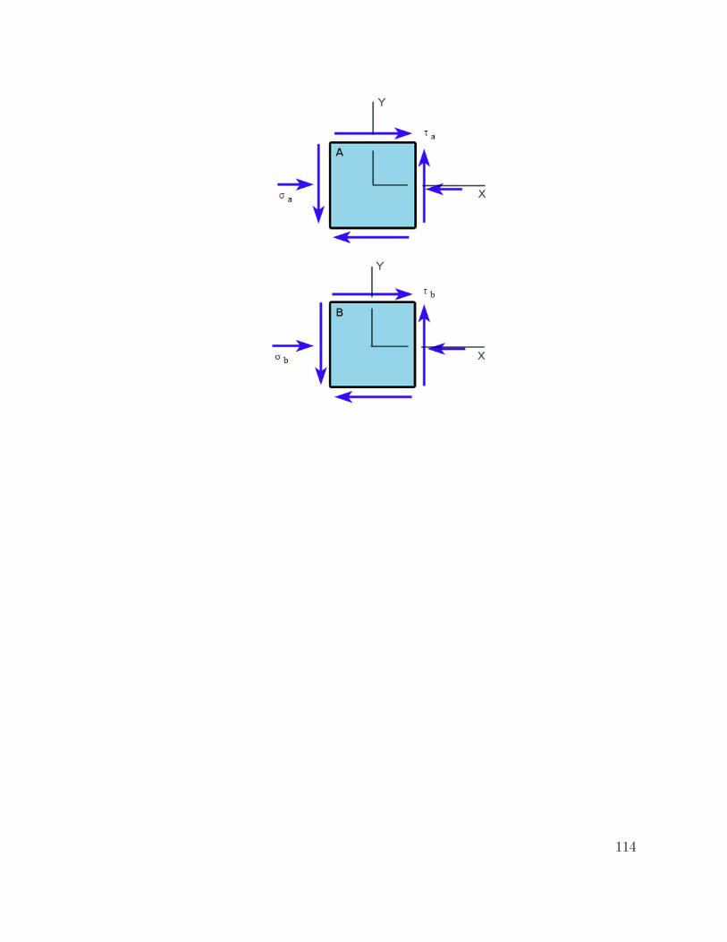
114
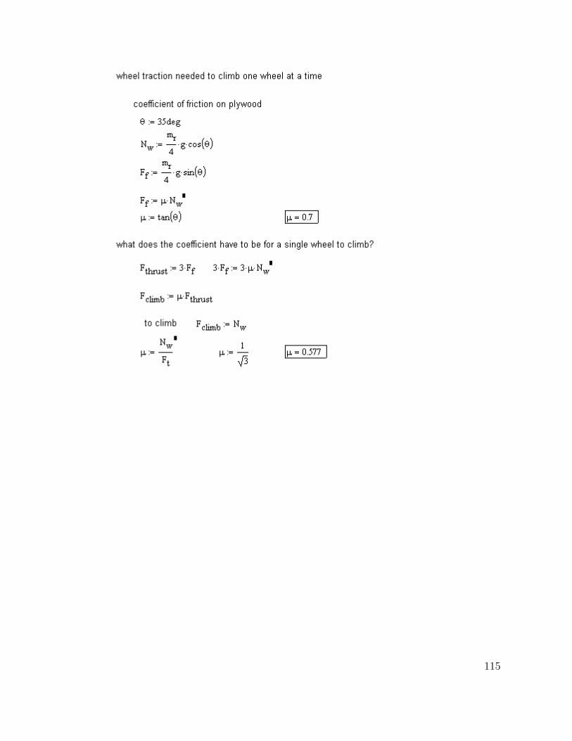
115
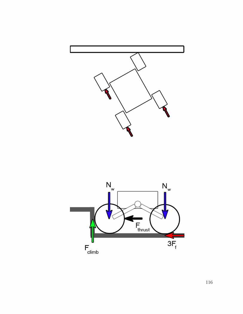
116
Appendix B
Mechanical Drawings
See attached CD.
117
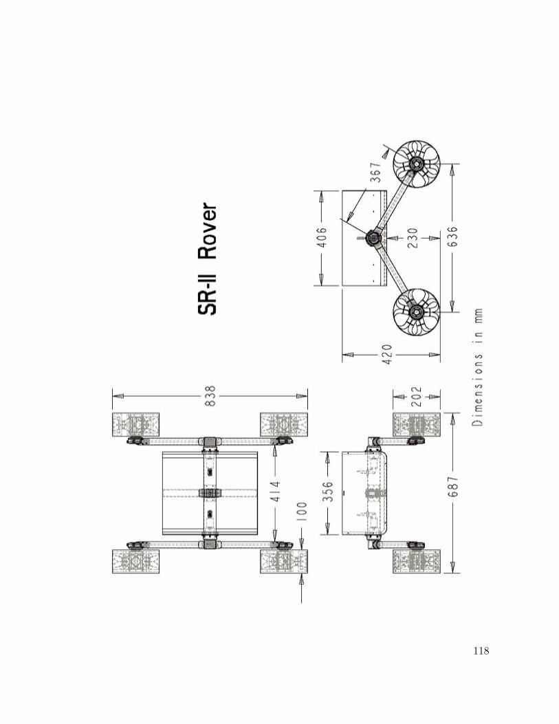
118