read.pudn.comread.pudn.com/downloads598/doc/2441136/opc ua part 9 - alarms … · release 1.02 iii...
TRANSCRIPT

F O U N D A T I O N
®
OPC Unified Architecture
Specification
Part 9: Alarms & Conditions
Release 1.02
July 24, 2012

OPC Unified Architecture, Part 9 ii Release 1.02
Specification Type:
Industry Standard Specification
Comments:
Title: OPC Unified
Architecture Part 9 :Alarms & Conditions
Date: July 24, 2012
Version: Release 1.02 Software: MS-Word
Source: OPC UA Part 9 - Alarms and Conditions 1.02 Specification.doc
Author: OPC Foundation Status: Release

Release 1.02 iii OPC Unified Architecture, Part 9
CONTENTS
Page
FOREWORD .......................................................................................................................... x
AGREEMENT OF USE ........................................................................................................... x
Revision 1.2 Highlights .......................................................................................................... xii
1 Scope .............................................................................................................................. 1
2 Normative References ..................................................................................................... 1
3 Terms, definitions, and abbreviations ............................................................................... 1
3.1 OPC UA Part 1 terms .............................................................................................. 1
3.2 OPC UA Part 3 terms .............................................................................................. 2
3.3 OPC UA Part 5 terms .............................................................................................. 2
3.4 OPC UA Alarms and Condition terms ...................................................................... 2
3.4.1 Acknowledge ............................................................................................... 2
3.4.2 Active .......................................................................................................... 2
3.4.3 ConditionClass ............................................................................................. 2
3.4.4 ConditionBranch .......................................................................................... 3
3.4.5 ConditionSource .......................................................................................... 3
3.4.6 Confirm ........................................................................................................ 3
3.4.7 Disable ........................................................................................................ 3
3.4.8 Operator ...................................................................................................... 3
3.4.9 Refresh ........................................................................................................ 3
3.4.10 Retain .......................................................................................................... 3
3.4.11 Shelving ....................................................................................................... 3
3.4.12 Suppress ..................................................................................................... 3
3.5 Abbreviations and symbols ...................................................................................... 4
3.6 Used data types ...................................................................................................... 4
4 Concepts ......................................................................................................................... 4
4.1 General ................................................................................................................... 4
4.2 Conditions ............................................................................................................... 4
4.3 Acknowledgeable Conditions ................................................................................... 6
4.4 Previous States of Conditions ................................................................................. 7
4.5 Condition State Synchronization .............................................................................. 7
4.6 Severity, Quality, and Comment .............................................................................. 8
4.7 Dialogs .................................................................................................................... 8
4.8 Alarms .................................................................................................................... 9
4.9 Multiple Active States ............................................................................................ 10
4.10 Condition Instances in the Address Space ............................................................. 10
4.11 Alarm and Condition Auditing ................................................................................ 11
5 Model ............................................................................................................................ 12
5.1 General ................................................................................................................. 12
5.2 Two-State State Machines ..................................................................................... 12
5.3 Condition Variables ............................................................................................... 13
5.4 Substate Reference Types .................................................................................... 14
5.4.1 General ...................................................................................................... 14
5.4.2 HasTrueSubState ReferenceType .............................................................. 14
5.4.3 HasFalseSubState ReferenceType............................................................. 14
5.5 Condition Model .................................................................................................... 15

OPC Unified Architecture, Part 9 iv Release 1.02
5.5.1 General ...................................................................................................... 15
5.5.2 ConditionType ............................................................................................ 16
5.5.3 Condition and Branch Instances ................................................................. 19
5.5.4 Disable Method .......................................................................................... 19
5.5.5 Enable Method ........................................................................................... 20
5.5.6 AddComment Method ................................................................................. 20
5.5.7 ConditionRefresh Method ........................................................................... 21
5.6 Dialog Model ......................................................................................................... 23
5.6.1 General ...................................................................................................... 23
5.6.2 DialogConditionType .................................................................................. 23
5.6.3 Respond Method ........................................................................................ 24
5.7 Acknowledgeable Condition Model ........................................................................ 26
5.7.1 General ...................................................................................................... 26
5.7.2 AcknowledgeableConditionType................................................................. 26
5.7.3 Acknowledge Method ................................................................................. 27
5.7.4 Confirm Method ......................................................................................... 28
5.8 Alarm Model .......................................................................................................... 29
5.8.1 General ...................................................................................................... 29
5.8.2 AlarmConditionType ................................................................................... 29
5.8.2.1 ShelvedStateMachineType ........................................................... 31
5.8.2.2 Unshelve Method ......................................................................... 34
5.8.2.3 TimedShelve Method ................................................................... 34
5.8.2.4 OneShotShelve Method ............................................................... 35
5.8.3 LimitAlarmType .......................................................................................... 35
5.8.4 ExclusiveLimit Types ................................................................................. 36
5.8.4.1 Overview ..................................................................................... 36
5.8.4.2 ExclusiveLimitStateMachineType ................................................. 37
5.8.4.3 ExclusiveLimitAlarmType ............................................................. 39
5.8.5 NonExclusiveLimitAlarmType ..................................................................... 40
5.8.6 Level Alarm ................................................................................................ 41
5.8.6.1 Overview ..................................................................................... 41
5.8.6.2 NonExclusiveLevelAlarmType ...................................................... 41
5.8.6.3 ExclusiveLevelAlarmType ............................................................ 41
5.8.7 Deviation Alarm ......................................................................................... 41
5.8.7.1 Overview ..................................................................................... 41
5.8.7.2 NonExclusiveDeviationAlarmType ................................................ 42
5.8.7.3 ExclusiveDeviationAlarmType ...................................................... 42
5.8.8 Rate of Change .......................................................................................... 42
5.8.8.1 Overview ..................................................................................... 42
5.8.8.2 NonExclusiveRateOfChangeAlarmType ....................................... 43
5.8.8.3 ExclusiveRateOfChangeAlarmType .............................................. 43
5.8.9 Discrete Alarms ......................................................................................... 44
5.8.9.1 DiscreteAlarmType ...................................................................... 44
5.8.9.2 OffNormalAlarmType ................................................................... 44
5.8.9.3 SystemOffNormalAlarmType ........................................................ 45
5.8.9.4 TripAlarmType ............................................................................. 45
5.9 ConditionClasses .................................................................................................. 46
5.9.1 Overview.................................................................................................... 46
5.9.1.1 Base ConditionClassType ............................................................ 46

Release 1.02 v OPC Unified Architecture, Part 9
5.9.1.2 ProcessConditionClassType ........................................................ 47
5.9.1.3 MaintenanceConditionClassType ................................................. 47
5.9.1.4 SystemConditionClassType ......................................................... 47
5.10 Audit Events .......................................................................................................... 48
5.10.1 Overview.................................................................................................... 48
5.10.2 AuditConditionEventType ........................................................................... 48
5.10.3 AuditConditionEnableEventType ................................................................ 49
5.10.4 AuditConditionCommentEventType ............................................................ 49
5.10.5 AuditConditionRespondEventType ............................................................. 49
5.10.6 AuditConditionAcknowledgeEventType ...................................................... 50
5.10.7 AuditConditionConfirmEventType ............................................................... 50
5.10.8 AuditConditionShelvingEventType ............................................................. 50
5.11 Condition Refresh Related Events ......................................................................... 50
5.11.1 Overview.................................................................................................... 50
5.11.2 RefreshStartEventType .............................................................................. 51
5.11.3 RefreshEndEventType ............................................................................... 51
5.11.4 RefreshRequiredEventType ....................................................................... 51
5.12 HasCondition Reference Type ............................................................................... 52
5.13 Alarm & Condition Status Codes ........................................................................... 52
5.14 Expected A&C Server Behaviours ......................................................................... 53
5.14.1 Communication problems ........................................................................... 53
5.14.2 Redundant A&C Servers ............................................................................ 53
6 AddressSpace Organisation ........................................................................................... 54
6.1 General ................................................................................................................. 54
6.2 Event Notifier and Source Hierarchy ...................................................................... 54
6.3 Adding Conditions to the Hierarchy ....................................................................... 54
6.4 Conditions in InstanceDeclarations ....................................................................... 55
6.5 Conditions in a VariableType ................................................................................. 55
Annex A (informative): Recommended Localized Names ...................................................... 57
A.1 Recommended State Names for TwoState Variables ............................................. 57
A.1.1 LocaleId “en”.............................................................................................. 57
A.1.2 LocaleId “de”.............................................................................................. 57
A.1.3 LocaleId “fr” ............................................................................................... 58
A.2 Recommended Dialog Response Options .............................................................. 59
Annex B (informative): Examples .......................................................................................... 60
B.1 Examples for Event sequences from Condition instances ...................................... 60
B.1.1 Overview.................................................................................................... 60
B.1.2 Server Maintains Current State Only .......................................................... 60
B.1.3 Server Maintains Previous States .............................................................. 60
B.2 Address Space Examples ...................................................................................... 62
Annex C (informative): Mapping to EEMUA .......................................................................... 64
Annex D (informative): Mapping from OPC A&E to OPC UA A&C ......................................... 65
D.1 Overview ............................................................................................................... 65
D.1.1 Alarms and Events COM UA Wrapper ........................................................ 65
D.1.1.1 Event Areas ................................................................................. 65
D.1.1.2 Event Sources ............................................................................. 65
D.1.1.3 Event Categories ......................................................................... 66
D.1.1.4 Event Attributes ........................................................................... 67

OPC Unified Architecture, Part 9 vi Release 1.02
D.1.1.5 Event Subscriptions ..................................................................... 67
D.1.1.6 Condition Instances ..................................................................... 69
D.1.1.7 Condition Refresh ........................................................................ 69
D.1.2 Alarms and Events COM UA Proxy ............................................................ 70
D.1.2.1 Server Status Mapping................................................................. 70
D.1.2.2 Browse Mapping .......................................................................... 76
D.1.2.3 Qualified Names .......................................................................... 77
D.1.2.4 Subscription Filters ...................................................................... 78
Release 1.02 vii OPC Unified Architecture, Part 9
FIGURES
Figure 1 – Base Condition State Model .................................................................................. 5
Figure 2 - AcknowledgeableConditions State Model ............................................................... 6
Figure 5 – Alarm State Machine Model ................................................................................... 9
Figure 6 – Multiple Active States Example ............................................................................ 10
Figure 7 - ConditionType Hierarchy ...................................................................................... 12
Figure 8 - Condition Model ................................................................................................... 16
Figure 9 - DialogConditionType Overview ............................................................................. 23
Figure 10 - AcknowledgeableConditionType Overview ......................................................... 26
Figure 11 – AlarmConditionType Hierarchy Model ................................................................ 29
Figure 12 - Alarm Model ....................................................................................................... 30
Figure 13 - Shelve state transitions ...................................................................................... 32
Figure 14 - Shelved State Machine Model ............................................................................ 32
Figure 15 - LimitAlarmType .................................................................................................. 36
Figure 16 - ExclusiveLimitStateMachine ............................................................................... 37
Figure 17 - ExclusiveLimitAlarmType .................................................................................... 39
Figure 18 - NonExclusiveLimitAlarmType ............................................................................. 40
Figure 19 - DiscreteAlarmType Hierarchy ............................................................................. 44
Figure 20 - ConditionClass Type Hierarchy .......................................................................... 46
Figure 21 – AuditEvent Hierarchy ......................................................................................... 48
Figure 22 – Refresh Related Event Hierarchy ....................................................................... 50
Figure 23 – Typical Event Hierarchy ..................................................................................... 54
Figure 24 – Use of HasCondition in an Event Hierarchy ....................................................... 55
Figure 25 – Use of HasCondition in an InstanceDeclaration ................................................. 55
Figure 26 – Use of HasCondition in a VariableType .............................................................. 56
Figure 27 – Single State Example ........................................................................................ 60
Figure 28 – Previous State Example ..................................................................................... 61
Figure 29 – HasCondition used with Condition instances ...................................................... 62
Figure 30 – HasCondition reference to a Condition Type ...................................................... 63
Figure 31 – HasCondition used with an instance declaration ................................................ 63
Figure 32 – The Type Model of a Wrapped COM AE Server ................................................. 67
Figure 33 – Mapping UA Event Types to COM A&E Event Types.......................................... 71
Figure 34 – Example Mapping of UA Event Types to COM A&E Categories .......................... 72
Figure 35 – Example Mapping of UA Event Types to A&E Categories with Attributes ........... 76

OPC Unified Architecture, Part 9 viii Release 1.02
TABLES Table 1 – Parameter Types defined in Part 3 .......................................................................... 4
Table 2 – Parameter Types defined in Part 4 .......................................................................... 4
Table 3 – TwoStateVariableType Definition .......................................................................... 13
Table 4 – ConditionVariableType Definition .......................................................................... 14
Table 5 – HasTrueSubState ReferenceType ......................................................................... 14
Table 6 – HasFalseSubState ReferenceType ....................................................................... 15
Table 7 – ConditionType Definition ....................................................................................... 17
Table 8 - Simple Attribute Operand ...................................................................................... 19
Table 9 - Disable Result Codes ............................................................................................ 20
Table 10 – Disable Method AddressSpace Definition ............................................................ 20
Table 11 - Enable Result Codes ........................................................................................... 20
Table 12 – Enable Method AddressSpace Definition ............................................................ 20
Table 13 AddComment Arguments ....................................................................................... 21
Table 14 - AddComment result Codes .................................................................................. 21
Table 15 – AddComment Method AddressSpace Definition .................................................. 21
Table 16 _ ConditionRefresh Parameters ............................................................................. 22
Table 17 - ConditionRefresh ReturnCodes ........................................................................... 22
Table 18 – ConditionRefresh Method AddressSpace Definition ............................................ 22
Table 19 – DialogConditionType Definition ........................................................................... 23
Table 20 - Repond Parameters ............................................................................................. 24
Table 21 - Respond ResultCodes ......................................................................................... 24
Table 22 – Respond Method AddressSpace Definition ......................................................... 25
Table 23 – AcknowledgeableConditionType Definition .......................................................... 26
Table 24 - Acknowledge Parameters .................................................................................... 27
Table 25 Acknowledge result codes ..................................................................................... 27
Table 26 – Acknowledge Method AddressSpace Definition ................................................... 28
Table 27 – Confirm Method Parameters ............................................................................... 28
Table 28 - Confirm Result Codes .......................................................................................... 28
Table 29 – Confirm Method AddressSpace Definition ........................................................... 29
Table 30 – AlarmConditionType Definition ............................................................................ 30
Table 31 –ShelvedStateMachine Definition .......................................................................... 33
Table 32 – ShelvedStateMachine Transitions ....................................................................... 33
Table 33 - Unshelve Result Codes ....................................................................................... 34
Table 34 – Unshelve Method AddressSpace Definition ......................................................... 34
Table 35 - TimedShelve Parameters .................................................................................... 34
Table 36 - TimedShelve Result Codes .................................................................................. 34
Table 37 – TimedShelve Method AddressSpace Definition ................................................... 35
Table 38 - OneShotShelve Result Codes .............................................................................. 35
Table 39 – OneShotShelve Method AddressSpace Definition ............................................... 35
Table 40 –LimitAlarmType Definition .................................................................................... 36
Table 41 – ExclusiveLimitStateMachineType Definition ........................................................ 37
Table 42 – ExclusiveLimitStateMachineType Transitions ...................................................... 38

Release 1.02 ix OPC Unified Architecture, Part 9
Table 43 – ExclusiveLimitAlarmType Definition .................................................................... 39
Table 44 – NonExclusiveLimitAlarmType Definition .............................................................. 40
Table 45 – NonExclusiveLevelAlarmType Definition ............................................................. 41
Table 46 – ExclusiveLevelAlarmType Definition ................................................................... 41
Table 47 – NonExclusiveDeviationAlarmType Definition ....................................................... 42
Table 48 – ExclusiveDeviationAlarmType Definition ............................................................. 42
Table 49 – NonExclusiveRateOfChangeAlarmType Definition ............................................... 43
Table 50 – ExclusiveRateOfChangeAlarmType Definition ..................................................... 43
Table 51 – DiscreteAlarmType Definition .............................................................................. 44
Table 52 – OffNormalAlarmType Definition ........................................................................... 44
Table 53 – SystemOffNormalAlarmType Definition ............................................................... 45
Table 54 – TripAlarmType Definition .................................................................................... 45
Table 55 – BaseConditionClassType Definition .................................................................... 46
Table 56 – ProcessConditionClassType Definition ................................................................ 47
Table 57 – MaintenanceConditionClassType Definition ........................................................ 47
Table 58 – SystemConditionClassType Definition ................................................................. 48
Table 59 – AuditConditionEventType Definition .................................................................... 48
Table 60 – AuditConditionEnableEventType Definition ......................................................... 49
Table 61 – AuditConditionCommentEventType Definition ..................................................... 49
Table 62 – AuditConditionRespondEventType Definition ...................................................... 49
Table 63 – AuditConditionAcknowledgeEventType Definition................................................ 50
Table 64 – AuditConditionConfirmEventType Definition ........................................................ 50
Table 65 – AuditConditionShelvingEventType Definition ....................................................... 50
Table 66 – RefreshStartEventType Definition ....................................................................... 51
Table 67 – RefreshEndEventType Definition ........................................................................ 51
Table 68 – RefreshRequiredEventType Definition ................................................................ 51
Table 69 – HasCondition ReferenceType ............................................................................. 52
Table 70 – Alarm & Condition Result Codes ......................................................................... 52
Table 71 – Recommended state names for LocaleId “en” ..................................................... 57
Table 72 – Recommended display names for LocaleId “en” .................................................. 57
Table 73 – Recommended state names for LocaleId “de” ..................................................... 57
Table 74 – Recommended display names for LocaleId “de” .................................................. 57
Table 75 – Recommended state names for LocaleId “fr” ....................................................... 58
Table 76 – Recommended display names for LocaleId “fr” .................................................... 58
Table 77 – Recommended Dialog Response Options ........................................................... 59
Table 78 – Example of a Condition that only keeps the latest state ...................................... 60
Table 79 – Example of a Condition that maintains previous states via branches ................... 61
Table 80 –EEMUA Terms ..................................................................................................... 64
Table 81 – Mapping from Standard Event Categories to OPC UA Event Types ..................... 66
Table 82 – Mapping from ONEVENTSTRUCT fields to UA BaseEventType Variables ........... 68
Table 83 – Mapping from ONEVENTSTRUCT fields to UA AuditEventType Variables ........... 68
Table 84 – Mapping from ONEVENTSTRUCT fields to UA AlarmType Variables .................. 69
Table 85 – Event Category Attribute Mapping Table ............................................................. 73

OPC Unified Architecture, Part 9 x Release 1.02
OPC FOUNDATION
UNIFIED ARCHITECTURE –
FOREWORD
This specification is the specification for developers of OPC UA applications. The specification is a result of an analysis and design process to develop a standard interface to facilitate the development of applications by multiple vendors that inter-operate seamlessly together.
Copyright © 2006-2012, OPC Foundation, Inc.
AGREEMENT OF USE
COPYRIGHT RESTRICTIONS
Any unauthorized use of this specification may violate copyright laws, trademark laws, and communications regulations and statutes. This document contains information which is protected by copyright. All Rights Reserved. No part of this work covered by copyright herein may be reproduced or used in any form or by any means--graphic, electronic, or mechanical, including photocopying, recording, taping, or information storage and retrieval systems --without permission of the copyright owner.
OPC Foundation members and non-members are prohibited from copying and redistributing this specification. All copies must be obtained on an individual basis, directly from the OPC Foundation Web site HTUhttp://www.opcfoundation.org UTH.
PATENTS
The attention of adopters is directed to the possibility that compliance with or adoption of OPC specifications may require use of an invention covered by patent rights. OPC shall not be responsible for identifying patents for which a license may be required by any OPC specification, or for conducting legal inquiries into the legal validity or scope of those patents that are brought to its attention. OPC specifications are prospective and advisory only. Prospective users are responsible for protecting themselves against liability for infringement of patents.
WARRANTY AND LIABILITY DISCLAIMERS
WHILE THIS PUBLICATION IS BELIEVED TO BE ACCURATE, IT IS PROVIDED "AS IS" AND MAY CONTAIN ERRORS OR MISPRINTS. THE OPC FOUDATION MAKES NO WARRANTY OF ANY KIND, EXPRESSED OR IMPLIED, WITH REGARD TO THIS PUBLICATION, INCLUDING BUT NOT LIMITED TO ANY WARRANTY OF TITLE OR OWNERSHIP, IMPLIED WARRANTY OF MERCHANTABILITY OR WARRANTY OF FITNESS FOR A PARTICULAR PURPOSE OR USE. IN NO EVENT SHALL THE OPC FOUNDATION BE LIABLE FOR ERRORS CONTAINED HEREIN OR FOR DIRECT, IND IRECT, INCIDENTAL, SPECIAL, CONSEQUENTIAL, RELIANCE OR COVER DAMAGES, INCLUDING LOSS OF PROFITS, REVENUE, DATA OR USE, INCURRED BY ANY USER OR ANY THIRD PARTY IN CONNECTION WITH THE FURNISHING, PERFORMANCE, OR USE OF THIS MATERIAL, EVEN IF ADVISED OF THE P OSSIBILITY OF SUCH DAMAGES.
The entire risk as to the quality and performance of software developed using this specification is borne by you.
RESTRICTED RIGHTS LEGEND
This Specification is provided with Restricted Rights. Use, duplication or disclosure by the U.S. government is subject to restrictions as set forth in (a) this Agreement pursuant to DFARs 227.7202-3(a); (b) subparagraph (c)(1)(i) of the Rights in Technical Data and Computer Software clause at DFARs 252.227-7013; or (c) the Commercial Computer Software Restricted Rights clause at FAR 52.227-19 subdivision (c)(1) and (2), as applicable. Contractor / manufacturer are the OPC Foundation,. 16101 N. 82nd Street, Suite 3B, Scottsdale, AZ, 85260 -1830
COMPLIANCE
The OPC Foundation shall at all times be the sole entity that may authorize developers, suppliers and sellers of hardware and software to use certification marks, trademarks or other special designations to indicate compliance with these

Release 1.02 xi OPC Unified Architecture, Part 9
materials. Products developed using this specification may claim compliance or conformance with this specification if and only if the software satisfactorily meets the certification requirements set by the OPC Foundation. Products that do not meet these requirements may claim only that the product was based on this specification and must not claim compliance or conformance with this specification.
TRADEMARKS
Most computer and software brand names have trademarks or registered trademarks. The individual trademarks have not been listed here.
GENERAL PROVISIONS
Should any provision of this Agreement be held to be void, invalid, unenforceable or illegal by a court, the validity and enforceability of the other provisions shall not be affected thereby.
This Agreement shall be governed by and construed under the laws o f the State of Minnesota, excluding its choice or law rules.
This Agreement embodies the entire understanding between the parties with respect to, and supersedes any prior understanding or agreement (oral or written) relating to, this specification.
ISSUE REPORTING
The OPC Foundation strives to maintain the highest quality standards for its published specifications, hence they undergo constant review and refinement. Readers are encouraged to report any issues and view any existing errata here: HTUhttp://www.opcfoundation.org/errata UTH

OPC Unified Architecture, Part 9 xii Release 1.02
Revision 1.2 Highlights
This revision includes various minor clarifications and an alternative variant to expose multistate discrete types. The following table includes the Mantis issues resolved with this revision.
Mantis ID
Summary Resolution
698 Condition State Synchronization for redundancy
Added section to describe expect behaviours for a server that implements redundancy and the A&C Information Model with respect to the A&C Information Model
795 Better definition needed for "Process", "System" and "Maintenance" Condition class types
Added additional text to define the three class of Alarms and Conditions
967 Need clarification about status codes for Read access to Condition fields
Added text to describe the expected functionality with respect to communication errors and status codes
1005 Various editorial changes / suggestions Made numerous editorial changes to clarify existing text or fix grammatical or spelling issues
1254 Clarifications regarding connection problems to underlying system
Added text to describe the expected functionality with respect to communication errors and status codes
1293 OffNormalAlarmType description needs update
Updated text as needed
1294 NormalState Property description needs improvement
Updated text as needed
1413 Definition of Comment field of ConditionType is too strict
Update to include a description of how to implement a null comment and an empty comment
1414 Clarification Quality / Missing Event fields
Updated the description of how quality is handled and what the expected behaviour is with regards to missing data.
1546 RefreshRequiredEventType and EventQueueOverflowEventType
Clarified text describing when each Event is used.
1622 DialogConditionType is abstract and should not be
Change to not abstract
1656 Need to update COM AE Mapping Updated the details of the COM AE mapping to reflect the actual code of the mapping. (i.e. to match what the actual mapping is)
1759 Check all Must Correct Must to shall and other grammatical mistakes
1815 AuditConditionEnableEventType Updated description of all Audit Condition Events to correctly list the required parameters for the given Event.
1855 Reporting bad status for event fields only if Retain==True
Updated text as required (5.5.2. and 5.14.1)
1854 In Figure 7, OffNormalEventType should be OffNormAlarmType
Fixed
Release 1.02 xiii OPC Unified Architecture, Part 9
Mantis ID
Summary Resolution
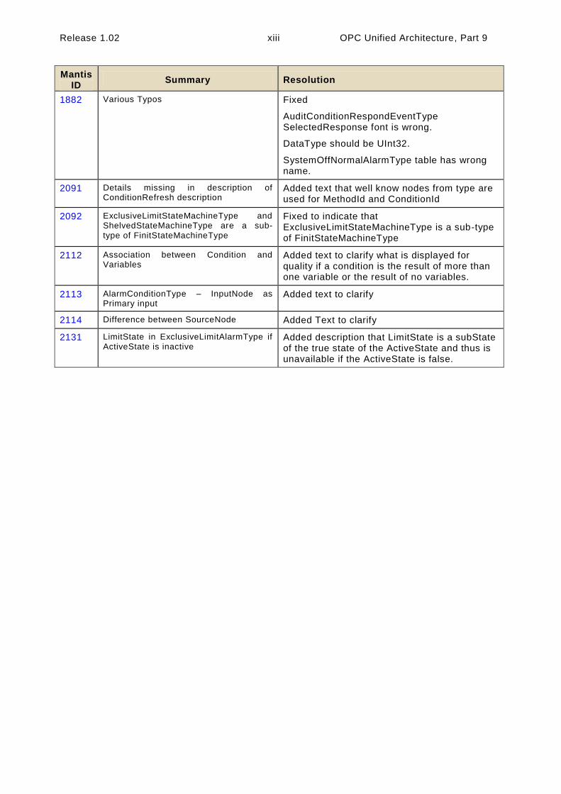
1882 Various Typos Fixed
AuditConditionRespondEventType SelectedResponse font is wrong.
DataType should be UInt32.
SystemOffNormalAlarmType table has wrong name.
2091 Details missing in description of ConditionRefresh description
Added text that well know nodes from type are used for MethodId and ConditionId
2092 ExclusiveLimitStateMachineType and ShelvedStateMachineType are a sub-type of FinitStateMachineType
Fixed to indicate that ExclusiveLimitStateMachineType is a sub-type of FinitStateMachineType
2112 Association between Condition and Variables
Added text to clarify what is displayed for quality if a condition is the result of more than one variable or the result of no variables.
2113 AlarmConditionType – InputNode as Primary input
Added text to clarify
2114 Difference between SourceNode Added Text to clarify
2131 LimitState in ExclusiveLimitAlarmType if ActiveState is inactive
Added description that LimitState is a subState of the true state of the ActiveState and thus is unavailable if the ActiveState is false.


Release 1.02 1 OPC Unified Architecture, Part 9
OPC Unified Architecture
Part 9: Alarms & Conditions
1 Scope
This standard specifies the representation of Alarms and Conditions in the OPC Unified Architecture. Included is the Information Model representation of Alarms and Conditions in the OPC UA address
space.
2 Normative References
Part 3: OPC UA Specification: Part 3 – Address Space Model
http://www.opcfoundation.org/UA/Part3/
Part 4: OPC UA Specification: Part 4 – Services
http://www.opcfoundation.org/UA/Part4/
Part 5: OPC UA Specification: Part 5 – Information Model
http://www.opcfoundation.org/UA/Part5/
Part 6: OPC UA Specification: Part 6 – Mappings
http://www.opcfoundation.org/UA/Part6/
Part 7: OPC UA Specification: Part 7 – Profiles
http://www.opcfoundation.org/UA/Part7/
Part 8: OPC UA Specification: Part 8 – Data Access
http://www.opcfoundation.org/UA/Part8/
Part 11: OPC UA Specification: Part 11 – Historical Access
http://www.opcfoundation.org/UA/Part11/
Additional external reference used to provide Information Model suggestions for this document:
EEMUA : 2nd Edition EEMUA 191 - Alarm System - A guide to design, management and procurement (Appendixes 6, 7, 8, 9).
http://www.eemua.co.uk/
3 Terms, definitions, and abbreviations
3.1 OPC UA Part 1 terms
The following terms defined in Part 1 of this multi-part standard apply.
AddressSpace
Alarm
Attribute
Client
Condition

OPC Unified Architecture, Part 9 2 Release 1.02
Event
Information Model
Message
Method
MonitoredItem
Node
NodeClass
Notification
Object
ObjectType
Reference
ReferenceType
Server
Service
Subscription
Variable
3.2 OPC UA Part 3 terms
The following terms defined in Part 3 of this multi-part standard apply.
EventType
ModelingRule
Property
3.3 OPC UA Part 5 terms
The following term defined in Part 5 of this multi-part standard apply.
ClientUserId
In addition base concepts like state machines and EventTypes defined in Part 5 are used in this specification.
3.4 OPC UA Alarms and Condition terms
3.4.1 Acknowledge
“a Operator action that indicates recognition of a new Alarm”
Note: as defined in EEMUA. The term “Accept” is another common term used to describe Acknowledge. They can be used interchangeably. This document will use Acknowledge.
3.4.2 Active
a state for an Alarm that indicates that the situation the Alarm is representing currently exists.
Note: Other common terms defined by EEMUA are “Standing” for an Active Alarm and “Cleared” when the Condition has returned to normal and is no longer Active.
3.4.3 ConditionClass
a Condition grouping that indicates in which domain or for what purpose a certain Condition is used.
Note: Some top-level ConditionClasses are defined in this specification. Vendors or organisations may derive more concrete classes or define different top-level classes.

Release 1.02 3 OPC Unified Architecture, Part 9
3.4.4 ConditionBranch
a specific state of a Condition.
Note: The Server can maintain ConditionBranches for the current state as well as for previous states .
3.4.5 ConditionSource
an element which a specific Condition is based upon or related to.
Note: Typically, it will be a Variable representing a process tag (e.g. FIC101) or an Object representing a device or subsystem.
In Events generated for Conditions, the SourceNode Property (inherited from the BaseEventType) will contain the NodeId of the ConditionSource.
3.4.6 Confirm
an operator action informing the Server that a corrective action has been taken to address the cause of the Alarm.
3.4.7 Disable
“system is configured such that the Alarm will not be generated even though the base Alarm Condition is present”
Note: This concept is further described in EEMUA
3.4.8 Operator
special user who is assigned to monitor and control a portion of a process
Note: “A Member of the operations team who is assigned to monitor and control a portion of the proce ss and is working at the control system‟s Console” as defined in EEMUA. In this standard an Operator is a special user. All descriptions that apply to general users also apply to Operators.
3.4.9 Refresh
the act of providing an update to an Event Subscription that provides all Alarms which are considered to be Retained.
Note: This concept is further described in EEMUA.
3.4.10 Retain
alarm in a state that is interesting for a Client wishing to synchronize its state of Conditions with the Server‟s state.
3.4.11 Shelving
“facility where the Operator is able to temporarily prevent an Alarm from being displayed to the Operator when it is causing the Operator a nuisance.
Note: A Shelved Alarm will be removed from the list and will not re-annunciate until un-shelved” as defined in EEMUA.
3.4.12 Suppress
the act of determining whether an Alarm should not occur

OPC Unified Architecture, Part 9 4 Release 1.02
Note: “An Alarm is suppressed when logical criteria are applied to determine that the Alarm should not occur, even though
the base Alarm Condition (e.g. Alarm setting exceeded) is present” as defined in EEMUA.
3.5 Abbreviations and symbols
DA Data Access UA Unified Architecture UML Unified Modelling Language XML Extensible Mark-up Language
3.6 Used data types
The following tables describe the data types that are used throughout this document. These types are separated into two tables. Base data types defined in Part 3 are in Table 1. The base types and data types defined in Part 4 are in Table 2.
Table 1 – Parameter Types defined in Part 3
Parameter Type
Argument
BaseDataType
NodeId
LocalizedText
Boolean
ByteString
Double
Duration
String
UInt16
Int32
UtcTime
Table 2 – Parameter Types defined in Part 4
Parameter Type
IntegerId
StatusCode
4 Concepts
4.1 General
This standard defines an Information Model for Conditions, Dialog Conditions, and Alarms including acknowledgement capabilities. It is built upon and extends base Event handling which is defined in Part 3, Part 4 and Part 5. This Information Model can also be extended to support the additional needs of specific domains. The details of what aspects of the Information Model are supported are provided via Profiles (see Part 7). It is expected that systems will provide historical Events and Conditions via the standard Historical Access framework (see Part 11).
4.2 Conditions
Conditions are used to represent the state of a system or one of its components. Some common examples are:
a temperature exceeding a configured limit
a device needing maintenance
a batch process that requires a user to confirm some step in the process before proceeding
Each Condition instance is of a specific ConditionType. The ConditionType and derived types are sub-types of the BaseEventType (see Part 3 and Part 5). This part defines types that are common across many industries. It is expected that vendors or other standardisation groups will define

Release 1.02 5 OPC Unified Architecture, Part 9
additional ConditionTypes deriving from the common base types defined in this part. The ConditionTypes supported by a Server are exposed in the AddressSpace of the Server.
Condition instances are specific implementations of a ConditionType. It is up to the Server whether such instances are also exposed in the Server’s AddressSpace. Clause 4.10 provides additional background about Condition instances. Condition instances shall have a unique identifier to differentiate them from other instances. This is independent of whether they are exposed in the AddressSpace.
As mentioned above, Conditions represent the state of a system or one of its components. In certain cases, however, previous states that still need attention also have to be maintained. ConditionBranches are introduced to deal with this requirement and distinguish current state and previous states. Each ConditionBranch has a BranchId that differentiates it from other branches of the same Condition instance. The ConditionBranch which represents the current state of the Condition (the trunk) has a Null BranchId. Servers can generate separate Event Notifications for each branch. When the state represented by a ConditionBranch does not need further attention, a final Event Notification for this branch will have the Retain Property set to False. Clause 4.4 provides more information and use cases. Maintaining previous states and therefore also the support of multiple branches is optional for Servers.
Conceptually, the lifetime of the Condition instance is independent of its state. However, Servers may provide access to Condition instances only while ConditionBranches exist.
The base Condition state model is illustrated in Figure 1. It is extended by the various Condition subtypes defined in this standard and may be further extended by vendors or other standardisation groups. The primary states of a Condition are disabled and enabled. The Disabled state is intended to allow Conditions to be turned off at the Server or below the Server (in a device or some underlying system). The Enabled state is normally extended with the addition of sub-states.
Figure 1 – Base Condition State Model
A transition into the Disabled state results in a Condition Event however no subsequent Event Notifications are generated until the Condition returns to the Enabled state.
When a Condition enters the Enabled state, that transition and all subsequent transitions result in Condition Events being generated by the Server.
If Auditing is supported by a Server, the following Auditing related action shall be performed. The Server will generate AuditEvents for Enable and Disable operations (either through a Method call or some Server / vendor – specific means), rather than generating an AuditEvent Notification for each Condition instance being enabled or disabled. For more information, see the definition of AuditConditionEnableEventType in Clause 5.10.2. AuditEvents are also generated for any other Operator action that results in changes to the Conditions.
Disabled
Enabled

OPC Unified Architecture, Part 9 6 Release 1.02
4.3 Acknowledgeable Conditions
AcknowledgeableConditions are sub-types of the base ConditionType. AcknowledgeableConditions expose states to indicate whether a Condition has to be acknowledged or confirmed.
An AckedState and a ConfirmedState extend the EnabledState defined by the Condition. The state model is illustrated in Figure 2. The enabled state is extended by adding the AckedState and (optionally) the ConfirmedState.
Figure 2 - AcknowledgeableConditions State Model
Acknowledgment of the transition may come from the Client or may be due to some logic internal to the Server. For example, acknowledgment of a related Condition may result in this Condition becoming acknowledged, or the Condition may be set up to automatically acknowledge itself when the acknowledgeable situation disappears.
Two Acknowledge state models are supported by this standard. Either of these state models can be extended to support more complex acknowledgement situations.
The basic Acknowledge state model is illustrated in Figure 3. This model defines an AckedState. The specific state changes that result in a change to the state depend on a Server‟s implementation. For example, in typical Alarm models the change is limited to a transition to the Active state or transitions within the Active state. More complex models however can also allow for changes to the AckedState when the Condition transitions to an inactive state.
Figure 3 – Acknowledge State Model
AckedState = TRUE
AckedState = FALSE
Ack By
Server
Acknowledge
Method
Disabled
Enabled
ConfirmedState = TRUE
AckedState = TRUE
ConfirmedState
= FALSE
AckedState = FALSE

Release 1.02 7 OPC Unified Architecture, Part 9
A more complex state model wich adds a confirmation to the basic Acknowledge is illustrated in Figure 4. The Confirmed Acknowledge model is typically used to differentiate between acknowledging the presence of a Condition and having done something to address the Condition. For example an Operator receiving a motor high temperature Notification calls the Acknowledge Method to inform the Server that the high temperature has been observed. The Operator then takes some action such as lowering the load on the motor in order to reduce the temperature. The Operator then calls the Confirm Method to inform the Server that a corrective action has been taken.
`Figure 4 – Confirmed Acknowledge State Model
4.4 Previous States of Conditions
Some systems require that previous states of a Condition are preserved for some time. A common use case is the acknowledgement process. In certain environments it is required to acknowledge both the transition into Active state and the transition into an inactive state. Systems with strict safety rules sometimes require that every transition into Active state has to be acknowledged. In situations where state changes occur in short succession there can be multiple unacknowledged states and the Server has to maintain ConditionBranches for all previous unacknowledged states. These branches will be deleted after they have been acknowledged or if they reached their final state.
Multiple ConditionBranches can also be used for other use cases where snapshots of previous states of a Condition require additional actions.
4.5 Condition State Synchronization
When a Client subscribes for Events, the Notification of transitions will begin at the time of the Subscription. The currently existing state will not be reported. This means for example that Clients are not informed of currently Active Alarms until a new state change occurs.
Clients can obtain the current state of all Condition instances that are in an interesting state, by requesting a Refresh for a Subscription. It should be noted that Refresh is not a general replay capability since the Server is not required to maintain an Event history.
Clients request a Refresh by calling the ConditionRefresh Method. The Server will respond with a RefreshStartEvent. This Event is followed by the Retained Conditions. The Server may also send new Event Notifications interspersed with the Refresh related Event Notifications. After the Server is done with the Refresh, a RefreshEndEvent is issued marking the completion of the Refresh. Clients shall check for multiple Event Notifications for a ConditionBranch to avoid overwriting a new state delivered together with an older state from the Refresh process. If a ConditionBranch exists, then the current Condition shall be reported. This is true even if the only interesting item regarding the
Confirmed by Server
Confirm Method
Acknowledged Unacknowledged
Acknowledge By Server
Acknowledge Method
Unconfirmed Confirmed
Server restricts to Unconfirmed until Acknowledged

OPC Unified Architecture, Part 9 8 Release 1.02
Condition is that ConditionBranches exist. This allows a Client to accurately represent the current Condition state.
A Client that wishes to display the current status of Alarms and Conditions (known as a “current Alarm display”) would use the following logic to process Refresh Event Notifications. The Client flags all Retained Conditions as suspect on reception of the Event of the RefreshStartEvent. The Client adds any new Events that are received during the Refresh without flagging them as suspect. The Client also removes the suspect flag from any Retained Conditions that are returned as part of the Refresh. When the Client receives a RefreshEndEvent, the Client removes any remaining suspect Events, since they no longer apply.
The following items should be noted with regard to ConditionRefresh:
As described in Clause 4.4 some systems require that previous states of a Condition are preserved for some time. Some Servers – in particular if they require acknowledgement of previous states – will maintain separate ConditionBranches for prior states that still need
attention.
ConditionRefresh shall issue Event Notifications for all interesting states (current and previous) of a Condition instance and Clients can therefore receive more than one Event for a Condition instance with different BranchIds.
Under some circumstances a Server may not be capable of ensuring the Client is fully in sync with the current state of Condition instances. For example if the underlying system represented by the Server is reset or communications are lost for some period of time the Server may need to resynchronize itself with the underlying system. In these cases the Server shall send an Event of the RefreshRequiredEventType to advise the Client that a Refresh may be necessary. A Client receiving this special Event should initiate a ConditionRefresh as noted in this clause.
To ensure a Client is always informed, the three special EventTypes (RefreshEndEventType, RefreshStartEventType and RefreshRequiredEventType) ignore the Event content filtering associated with a Subscription and will always be delivered to the Client.
4.6 Severity, Quality, and Comment
Comment, Severity and Quality are important elements of Conditions and any change to them will cause Event Notifications.
The Severity of a Condition is inherited from the base Event model defined in [UA Part 5]. It indicates the urgency of the Condition and is also commonly called „priority‟, especially in relation to Alarms in the ProcessConditionClass.
A Comment is a user generated string that is to be associated with a certain state of a Condition.
Quality refers to the quality of the data value(s) upon which this Condition is based. Since a Condition is usually based on one or more Variables, the Condition inherits the quality of these Variables. E.g., if the process value is “Uncertain”, the “LevelAlarm” Condition is also questionable. . If more than one variable is represented by a given condition or if the condition is from an underlining system and no direct mapping to a variable is available, it is up to the application to determine what quality is displayed as part of the condition.
4.7 Dialogs
Dialogs are ConditionTypes used by a Server to request user input. They are typically used when a Server has entered some state that requires intervention by a Client. For example a Server monitoring a paper machine indicates that a roll of paper has been wound and is ready for inspection. The Server would activate a Dialog Condition indicating to the user that an inspection is

Release 1.02 9 OPC Unified Architecture, Part 9
required. Once the inspection has taken place the user responds by informing the Server of an
accepted or unaccepted inspection allowing the process to continue.
4.8 Alarms
Alarms are specializations of AcknowledgeableConditions that add the concepts of an Active state, a Shelving state and a Suppressed state to a Condition. The state model is illustrated in Figure 5
Figure 5 – Alarm State Machine Model
An Alarm in the Active state indicates that the situation the Condition is representing currently exists. When an Alarm is an inactive state it is representing a situation that has returned to a normal state.
Some Alarm subtypes introduce sub-states of the Active state. For example an Alarm representing a temperature may provide a high level state as well as a critically high state (s ee following Clause).
The Shelving state can be set by an Operator via OPC UA Methods. The Suppressed state is set internally by the Server due to system specific reasons. Alarm systems typically implement the Suppress and Shelve features to help keep Operators from being overwhelmed during Alarm “storms” by limiting the number of Alarms an Operator sees on a current Alarm display. This is accomplished by setting the SuppressedOrShelved flag on second order dependent Alarms and/or Alarms of less severity, leading the Operator to concentrate on the most critical issues.
Disabled
Active = TRUE
Enabled
Active = FALSE
Suppressed = TRUE Suppressed = FALSE
Shelved Unshelved
ConfirmedState = TRUE
AckedState = TRUE
ConfirmedState
= FALSE
AckedState = FALSE

OPC Unified Architecture, Part 9 10 Release 1.02
The Shelved and Suppressed states differ from the Disabled state in that Alarms are still fully functional and can be included in Subscription Notifications to a Client.
4.9 Multiple Active States
In some cases it is desirable to further define the Active state of an Alarm by providing a sub-state machine for the Active State. For example a multi-state level Alarm when in the Active state may be in one of the following sub-states: LowLow, Low, High or HighHigh. The state model is illustrated in Figure 6.
Figure 6 – Multiple Active States Example
With the multi-state Alarm model, state transitions among the sub-states of Active are allowed without causing a transition out of the Active state.
To accommodate different use cases both a (mutually) exclusive and a non-exclusive model are supported.
Exclusive means that the Alarm can only be in one sub-state at a time. If for example a temperature exceeds the HighHigh limit the associated exclusive LevelAlarm will be in the HighHigh sub -state and not in the High sub-state.
Some Alarm systems, however, allow multiple sub-states to exist in parallel. This is called non-exclusive. In the previous example where the temperature exceeds the HighHigh limit a non -exclusive LevelAlarm will be both in the High and the HighHigh sub-state.
4.10 Condition Instances in the Address Space
Because Conditions always have a state (Enabled or Disabled) and possibly many sub-states it makes sense to have instances of Conditions present in the AddressSpace. If the Server exposes Condition instances they usually will appear in the AddressSpace as components of the Objects that “own” them. For example a temperature transmitter that has a built -in high temperature Alarm would
Active = FALSE
Active = TRUE
HighHigh LowLow
High Low

Release 1.02 11 OPC Unified Architecture, Part 9
appear in the AddressSpace as an instance of some temperature transmitter Object with a HasComponent Reference to an instance of a LevelAlarmType.
The availability of instances allows Data Access Clients to monitor the current Condition state by subscribing to the Attribute values of Variable Nodes.
While exposing Condition instances in the AddressSpace is not always possible, doing so allows for direct interaction (read, write and Method invocation) with a specific Condition instance. For example, if a Condition instance is not exposed, there is no way to invoke the Enable or Disable Method for the specific Condition instance.
4.11 Alarm and Condition Auditing
The OPC UA Standards include provisions for auditing. Auditing is an important security and tracking concept. Audit records provide the “Who”, “When” and “What” information regarding user interactions with a system. These audit records are especially important when Alarm management is considered. Alarms are the typical instrument for providing information to a user that something needs the user‟s attention. A record of how the user reacts to this information is required in many cases. Audit records are generated for all Method calls that affect the state of the system, for example an Acknowledge Method call would generate an AuditConditionAck Event.
The standard AuditEventTypes defined in Part 5 already includes the fields required for Condition related audit records. To allow for filtering and grouping, this standard defines a number of sub-types of the AuditEventTypes but without adding new fields to them.
This standard describes the AuditEventType that each Method is required to generate. For example, the Disable Method has an AlwaysGeneratesEvent Reference to an AuditConditionEnableEventType. An Event of this type shall be generated for every invocation of the Method. The audit Event describes the user interaction with the system, in some cases this interaction may affect more than one Condition or be related to more than one state.

OPC Unified Architecture, Part 9 12 Release 1.02
5 Model
5.1 General
The Alarm and Condition model extends the OPC UA base Event model by defining various Event Types based on the BaseEventType. All of the Event Types defined in this standard can be further extended to form domain or Server specific Alarm and Condition Types.
Instances of Alarm and Condition Types may be optionally exposed in the AddressSpace in order to allow direct access to the state of an Alarm or Condition.
The following sub clauses define the OPC UA Alarm and Condition Types. Figure 7 informally describes the hierarchy of these Types. Subtypes of the LimitAlarmType and the DiscreteAlarmType are not shown. The full AlarmConditionType hierarchy can be found in Figure 11.
Defined in [UA Part 5]BaseEvent
Type
Acknowledgeable
Condition Type
RefreshStart
EventType
SystemEvent
Type
RefreshRequired
EventType
RefreshEnd
EventType
AlarmCondition
Type
DialogCondition
Type
ConditionType
StateMachine
Type
ExclusiveLimit
StateMachineType
Shelved
StateMachineType
LimitAlarm
Type
DiscreteAlarm
Type
OffNormalAlarm
Type
SystemOffNormal
AlarmType
Figure 7 - ConditionType Hierarchy
5.2 Two-State State Machines
Most states defined in this standard are simple – i.e. they are either TRUE or FALSE. The TwoStateVariableType is introduced specifically for this use case. More complex states are modelled by using a StateMachineType defined in Part 5.
The TwoStateVariableType is derived from the StateVariableType defined in Part 5 and formally defined in Table 3.

Release 1.02 13 OPC Unified Architecture, Part 9
Table 3 – TwoStateVariableType Definition
Attribute Value
BrowseName TwoStateVariableType
DataType LocalizedText
ValueRank -1 (-1 = Scalar)
IsAbstract False
References NodeClass BrowseName DataType TypeDefinition Modelling Rule
Subtype of the StateVariableType defined in Part 5.
Note that a Reference to this subtype is not shown in the definition of the StateVariableType
HasProperty Variable Id Boolean PropertyType Mandatory
HasProperty Variable TransitionTime UtcTime PropertyType Optional
HasProperty Variable EffectiveTransitionTime UtcTime PropertyType Optional
HasProperty Variable TrueState LocalizedText PropertyType Optional
HasProperty Variable FalseState LocalizedText PropertyType Optional
HasTrueSubState StateMachine or TwoStateVariableType
<StateIdentifier> Defined in Clause 5.4.2 Optional
HasFalseSubState StateMachine or TwoStateVariableType
<StateIdentifier> Defined in Clause 5.4.3 Optional
The Value Attribute of a TwoStateVariable contains the current state as a human readable name. The EnabledState for example, might contain the name “Enabled” when TRUE and “Disabled” when
FALSE.
Id is inherited from the StateVariableType and overridden to reflect the required DataType (Boolean). The value shall be the current state, i .e. either TRUE or FALSE.
TransitionTime specifies the time when the current state was entered.
EffectiveTransitionTime specifies the time when the current state or one of its sub states was entered. If, for example, a LevelAlarm is active and – while active – switches several times between High and HighHigh, then the TransitionTime stays at the point in time where the Alarm became active whereas the EffectiveTransitionTime changes with each shift of a sub state.
The optional Property EffectiveDisplayName from the StateVariableType is used if a state has sub states. It contains a human readable name for the current state after taking the state of any SubStateMachines in account. As an example, the EffectiveDisplayName of the EnabledState could contain “Active/HighHigh” to specify that the Condition is active and has exceeded the HighHigh limit.
Other optional Properties of the StateVariableType have no defined meaning for TwoStateVariables.
TrueState and FalseState contain the localized string for the TwoStateVariable value when its Id Property has the value TRUE or FALSE, respectively. Since the two Properties provide meta-data for the Type, Servers may not allow these Properties to be selected in the Event filter for a monitored item. Clients can use the Read Service to get the information from the specific ConditionType.
A HasTrueSubState Reference is used to indicate that the TRUE state has sub states.
A HasFalseSubState Reference is used to indicate that the FALSE state has sub states.
5.3 Condition Variables
Various information elements of a Condition are not considered to be states. However, a change in their value is considered important and supposed to trigger an Event Notification. These information elements are called ConditionVariables.
ConditionVariables are represented by a ConditionVariableType formally defined in Table 4.

OPC Unified Architecture, Part 9 14 Release 1.02
Table 4 – ConditionVariableType Definition
Attribute Value
BrowseName ConditionVariableType
DataType BaseDataType
ValueRank -2 (-2 = Any)
IsAbstract False
References NodeClass BrowseName DataType TypeDefinition Modelling Rule
Subtype of the BaseDataVariableType defined in Part 5.
HasProperty Variable SourceTimestamp UtcTime PropertyType Mandatory
SourceTimestamp indicates the time of the last change of the Value of this ConditionVariable. It shall be the same time that would be returned from the Read Service inside the DataValue structure for the ConditionVariable Value Attribute.
5.4 Substate Reference Types
5.4.1 General
This Clause defines ReferenceTypes that are needed beyond those already specified as part of Part 3 and Part 5 to extend TwoState state machines with substates. These References will only exist when substates are available.For example if a TwoState machine is in a FALSE State, then any SubStates referenced from the TRUE state will not be available. If an Event is generated while in the FALSE state and information from the TRUE state substate is part of the the data that is to be reported than this data would be reported as a NULL. With this approach TwoStateVariables can be extended with subordinate state machines in a similar fashion to the StateMachineType defined in
Part 5.
5.4.2 HasTrueSubState ReferenceType
The HasTrueSubState ReferenceType is a concrete ReferenceType that can be used directly. It is a subtype of the NonHierarchicalReferences ReferenceType.
The semantics indicate that the sub state (the target Node) is a subordinate state of the TRUE super state. If more than one state within a Condition is a sub state of the same super state (i.e. several HasTrueSubState References exist for the same super state) they are all treated as independent substates. The representation in the AddressSpace is specified in Table 5.
The SourceNode of the Reference shall be an instance of a TwoStateVariableType and the TargetNode shall either be an instance of a TwoStateVariableType or an instance of a subtype of a StateMachineType.
It is not required to provide the HasTrueSubState Reference from super state to sub state, but it is required that the sub state provides the inverse Reference (IsTrueSubStateOf) to its super state.
Table 5 – HasTrueSubState ReferenceType
Attributes Value
BrowseName HasTrueSubState
InverseName IsTrueSubStateOf
Symmetric False
IsAbstract False
References NodeClass BrowseName Comment
5.4.3 HasFalseSubState ReferenceType
The HasFalseSubState ReferenceType is a concrete ReferenceType that can be used directly. It is a subtype of the NonHierarchicalReferences ReferenceType.

Release 1.02 15 OPC Unified Architecture, Part 9
The semantics indicate that the sub state (the target Node) is a subordinate state of the FALSE super state. If more than one state within a Condition is a sub state of the same super state (i.e. several HasFalseSubState References exist for the same super state) they are all treated as independent substates. The representation in the AddressSpace is specified in Table 6.
The SourceNode of the Reference shall be an instance of a TwoStateVariableType and the TargetNode shall either be an instance of a TwoStateVariableType or an instance of a subtype of a StateMachineType.
It is not required to provide the HasFalseSubState Reference from super state to sub state, but it is required that the sub state provides the inverse Reference (IsFalseSubStateOf) to its super state.
Table 6 – HasFalseSubState ReferenceType
Attributes Value
BrowseName HasFalseSubState
InverseName IsFalseSubStateOf
Symmetric False
IsAbstract False
References NodeClass BrowseName Comment
5.5 Condition Model
5.5.1 General
The Condition model extends the Event model by defining the ConditionType. The ConditionType introduces the concept of states differentiating it from the base Event model. Unlike the BaseEventTypes, Conditions are not transient. The ConditionType is further extended into Dialog and AcknowledgeableConditionTypes, each of which have their own sub-types.
The Condition model is illustrated in Figure 8 and formally defined in the subsequent tables. It is worth noting that this figure, like all figures in this document, is not intended to be complete. Rather, the figures only illustrate information provided by the formal definitions.

OPC Unified Architecture, Part 9 16 Release 1.02
ConditionType
PropertyType:
Retain
ConditionRefresh
TwoStateVariableType:
EnableState
ConditionVariableType:
Quality
Disable
ClientUserId
AddComment
ConditionVariableType:
Comment
BaseEventType
Enable
Acknowledgeable
ConditionType
Dialog
ConditionType
ConditionVariableType:
LastSeverity
PropertyType:
BranchId
PropertyType:
ConditionNamePropertyType:
ConditionClassId
PropertyType:
ConditionClassName
Figure 8 - Condition Model
5.5.2 ConditionType
The ConditionType defines all general characteristics of a Condition. All other ConditionTypes derive from it. It is formally defined in Table 7. The FALSE state of the EnabledState shall not be extended
with a sub state machine.

Release 1.02 17 OPC Unified Architecture, Part 9
Table 7 – ConditionType Definition
Attribute Value
BrowseName ConditionType
IsAbstract True
References NodeClass BrowseName DataType TypeDefinition ModellingRule
Subtype of the BaseEventType defined in Part 5
HasSubtype ObjectType DialogConditionType Defined in Clause 5.6.2
HasSubtype ObjectType AcknowledgeableConditionType Defined in Clause 5.7.2
HasProperty Variable ConditionClassId NodeId PropertyType Mandatory
HasProperty Variable ConditionClassName LocalizedText PropertyType Mandatory
HasProperty Variable ConditionName String PropertyType Mandatory
HasProperty Variable BranchId NodeId PropertyType Mandatory
HasProperty Variable Retain Boolean PropertyType Mandatory
HasComponent Variable EnabledState LocalizedText TwoStateVariableType Mandatory
HasComponent Variable Quality StatusCode ConditionVariableType Mandatory
HasComponent Variable LastSeverity UInt16 ConditionVariableType Mandatory
HasComponent Variable Comment LocalizedText ConditionVariableType Mandatory
HasProperty Variable ClientUserId String PropertyType Mandatory
HasComponent Method Disable Defined in Clause 5.5.4 Mandatory
HasComponent Method Enable Defined in Clause 5.5.5 Mandatory
HasComponent Method AddComment Defined in Clause 5.5.6 Mandatory
HasComponent Method ConditionRefresh Defined in Clause 5.5.7 None
The ConditionType inherits all Properties of the BaseEventType. Their semantic is defined in Part 5. SourceNode identifies the ConditionSource. See Clause 5.12 for more details. If the ConditionSource is not a Node in the AddressSpace the NodeId is set to null. The SourceNode is the Node which the condition is associated with, it may be the same as the InputNode for an alarm, but it may be a separate node. . For example a motor, which is a variable with a value that is an RPM, may be the ConditionSource for Conditions that are related to the motor as well as a temperature sensor associated with the motor. In the former the InputNode for the High RPM alarm is the value of the Motor RPM, while in the later the InputNode of the High Alarm would be the value of the temperature sensor that is associated with the motor.
ConditionClassId specifies in which domain this Condition is used. It is the NodeId of the corresponding ConditionClassType. See clause 5.9 for the definition of ConditionClass and a set of ConditionClasses defined in this standard. When using this Property for filtering, Clients have to specify all individual ConditionClassType NodeIds. The OfType operator cannot be applied. BaseConditionClassType is used as class whenever a Condition cannot be assigned to a more
concrete class.
ConditionClassName provides the display name of the ConditionClassType.
ConditionName identifies the Condition instance that the Event originated from. It can be used together with the SourceName in a user display to distinguish between different Condition instances. If a ConditionSource has only one instance of a ConditionType, and the Server has no instance name, the Server shall supply the ConditionType browse name.
BranchId is Null for all Event Notifications that relate to the current state of the Condition instance. If BranchId is not Null it identifies a previous state of this Condition instance that still needs attention by an Operator. If the current ConditionBranch is transformed into a previous ConditionBranch then the Server needs to assign a non-null BranchId. An initial Event for the branch will generated with the values of the ConditionBranch and the new BranchId. The ConditionBranch can be updated many times before it is no longer needed. When the ConditionBranch no longer requires Operator input the final Event will have Retain set to FALSE. The retain bit on the current Event is TRUE, as long as any ConditionBranches require Operator input. See Clause 4.4 for more information about the need for creating and maintaining previous ConditionBranches and Annex B.1 for an example using branches. The BranchId DataType is NodeId although the Server is not required to have ConditionBranches in the Address Space. The use of a NodeId allows the Server to use simple
numeric identifiers, strings or arrays of bytes.

OPC Unified Architecture, Part 9 18 Release 1.02
Retain when TRUE describes a Condition (or ConditionBranch) as being in a state that is interesting for a Client wishing to synchronize its state with the Server‟s state. The logic to determine how this flag is set is Server specific. Typically all Active Alarms would have the Retain flag set; however, it is also possible for inactive Alarms to have their Retain flag set to TRUE.
In normal processing when a Client receives an Event with the Retain flag set to FALSE, the Client should consider this as a ConditionBranch that is no longer of interest, in the case of a “current Alarm display” the ConditionBranch would be removed from the display.
EnabledState indicates whether the Condition is enabled. EnabledState/Id is TRUE if enabled, FALSE otherwise. EnabledState/TransitionTime defines when the EnabledState last changed. Recommended state names are described in Annex A.
A Condition‟s EnabledState effects the generation of Event Notifications and as such results in the following specific behaviour:
When the Condition instance enters the Disabled state, the Retain Property of this Condition shall be set to FALSE by the Server to indicate to the Client that the Condition instance is currently not of interest to Clients.
When the Condition instance enters the enabled state, the Condition shall be evaluated and all of its Properties updated to reflect the current values. If this evaluation causes the Retain Property to transition to TRUE for any ConditionBranch, then an Event Notification shall be generated for that ConditionBranch.
The Server may choose to continue to test for a Condition instance while it is Disabled. However, no Event Notifications will be generated while the Condition instance is disabled.
For any Condition that exists in the AddressSpace the Attributes and the following Variables will continue to have valid values even in the Disabled state; EventId, Event Type, Source Node, Source Name, Time, and EnabledState. Other properties may no longer provide current valid values. All Variables that are no longer provided shall return a status of Bad_ConditionDisabled.
When enabled, changes to the following components shall cause a ConditionType Event Notification:
Quality
Severity (inherited from BaseEventType)
Comment
This may not be the complete list. Sub-Types may define additional Variables that trigger Event Notifications. In general changes to Variables of the types TwoStateVariableType or ConditionVariableType trigger Event Notifications.
Quality reveals the status of process values or other resources that this Condition instance is based upon. If, for example, a process value is “Uncertain”, the associated “LevelAlarm” Condition is also questionable. Values for the Quality can be any of the OPC StatusCodes defined in Part 8 (Data Access) as well as Good, Uncertain and Bad as defined in Part 4. These StatusCodes are similar to but slightly more generic than the description of data quality in the various Fieldbus Specifications. It is the responsibility of the Server to map internal status information to these codes. A Server which supports no quality information shall return Good. This quality can also reflect the communication status associated with the system that this value or resource is based on and from which this Alarm was received. For communication errors to the underlying system, especially those that result in some unavailable Event fields, the quality shall be Bad_NoCommunication error.
Events are only generated for Conditions that have their Retain field set to true.

Release 1.02 19 OPC Unified Architecture, Part 9
LastSeverity provides the previous severity of the ConditionBranch. Initially this Variable contains a zero value; it will return a value only after a severity change. The new severity is supplied via the Severity Property which is inherited from the BaseEventType.
Comment contains the last comment provided for a certain state (ConditionBranch). It may have been provided by an AddComment Method, some other Method or in some other manner. The initial value of this Variable is null, unless it is provided in some other manner . If a Method provides as an option the ability to set a Comment, then the value of this Variable is reset to null if an optional
comment is not provided.
ClientUserId is related to the Comment field and contains the identity of the user who inserted the most recent Comment. The logic to obtain the ClientUserId is defined in Part 5.
The NodeId of the Condition instance is used as ConditionId. It is not explicitly modelled as a component of the ConditionType. However, it can be requested with the following SimpleAttributeOperand in the SelectClause of the EventFilter:
Table 8 - Simple Attribute Operand
Name Type Description
SimpleAttributeOperand
typeId NodeId NodeId of the ConditionType Node
browsePath[] QualifiedName empty
attributeId IntegerId Id of the NodeId Attribute
5.5.3 Condition and Branch Instances
Conditions are Objects which have a state which changes over time. Each Condition instance has the ConditionId as identifier which uniquely identifies it within the Server.
A Condition instance may be an Object that appears in the Server Address Space. If this is the case the ConditionId is the NodeId for the Object.
The state of a Condition instance at any given time is the set values for the Variables that belong to the Condition instance. If one or more Variable values change the Server generates an Event with a unique EventId.
If a Client calls Refresh the Server will report the current state of a Condition instance by re-sending the last Event (i.e. the same EventId and Time is sent).
A ConditionBranch is a copy of the Condition instance state that can change independently of the current Condition instance state. Each Branch has an identifier called a BranchId which is unique among all active Branches for a Condition instance. Branches are typically not visible in the Address Space and this standard does not define a standard way to make them visible.
5.5.4 Disable Method
Disable used to change a Condition instance to the Disabled state. Normally, the MethodId passed to the Call Service is found by browsing the Condition instance in the AddressSpace. However, some Servers do not expose Condition instances in the AddressSpace. Therefore all Servers shall allow Clients to call the Disable Method by specifying ConditionId as the ObjectId and the well known NodeId of the Method declaration on the ConditionType as the MethodId.
Signature
Disable();
Method Result Codes (defined in Call Service)

OPC Unified Architecture, Part 9 20 Release 1.02
Table 9 - Disable Result Codes
ResultCode Description
Bad_ConditionAlreadyDisabled See Table 70 for the description of this result code.
Table 10 specifies the AddressSpace representation for the Disable Method.
Table 10 – Disable Method AddressSpace Definition
Attribute Value
BrowseName Disable
References NodeClass BrowseName DataType TypeDefinition ModellingRule
AlwaysGeneratesEvent Defined in 5.10.2 AuditConditionEnableEventType
5.5.5 Enable Method
Enable is used to change a Condition instance to the enabled state. Normally, the MethodId passed to the Call Service is found by browsing the Condition instance in the AddressSpace. However, some Servers do not expose Condition instances in the AddressSpace. Therefore all Servers shall allow Clients to call the Enable Method by specifying ConditionId as the ObjectId and the well known NodeId of the Method declaration on the ConditionType as the MethodId.
Signature
Enable();
Method Result Codes (defined in Call Service)
Table 11 - Enable Result Codes
ResultCode Description
Bad_ConditionAlreadyEnabled See Table 70 for the description of this result code.
Table 12 specifies the AddressSpace representation for the Enable Method.
Table 12 – Enable Method AddressSpace Definition
Attribute Value
BrowseName Enable
References NodeClass BrowseName DataType TypeDefinition ModellingRule
AlwaysGeneratesEvent Defined in 5.10.2 AuditConditionEnableEventType
5.5.6 AddComment Method
AddComment is used to apply a comment to a specific state of a Condition instance. Normally, the MethodId passed to the Call Service is found by browsing the Condition instance in the AddressSpace. However, some Servers do not expose Condition instances in the AddressSpace. Therefore all Servers shall allow Clients to call the AddComment Method by specifying ConditionId as the ObjectId and the well known NodeId of the Method declaration on the ConditionType as the MethodId. The Method cannot be called on the ConditionType Node.
Signature
AddComment(
[in] ByteString EventId
[in] LocalizedText Comment
);

Release 1.02 21 OPC Unified Architecture, Part 9
Table 13 AddComment Arguments
Argument Description
EventId EventId identifying a particular Event Notification where a state was reported for a Condition.
Comment A localized text to be applied to the Condition.
Method Result Codes (defined in Call Service)
Table 14 - AddComment result Codes
ResultCode Description
Bad_MethodInvalid See Part 4 for the description of this result code.
The addressed Condition does not support adding comments.
Bad_EventIdUnknown See Table 70 for the description of this result code.
Bad_NodeIdUnknown See Part 4 for the description of this result code.
Used to indicate that the specified Condition is not valid or that the Method was called on the ConditionType Node.
Comments
Comments are added to Event occurrences identified via an EventId. EventIds where the related EventType does not support Comments at all are rejected.
A ConditionEvent - where the Comment Variable contains this text - will be sent for the identified state. If a comment is added to a previous state (i.e. a state for which the Server has created a branch), the BranchId and all Condition values of this branch will be reported.
Table 15 specifies the AddressSpace representation for the AddComment Method.
Table 15 – AddComment Method AddressSpace Definition
Attribute Value
BrowseName AddComment
References NodeClass BrowseName DataType TypeDefinition ModellingRule
HasProperty Variable InputArguments Argument[] PropertyType Mandatory
AlwaysGenerates Event
Defined in 5.10.4 AuditConditionCommentEventType
5.5.7 ConditionRefresh Method
ConditionRefresh allows a Client to request a Refresh of all Condition instances that currently are in an interesting state (they have the Retain flag set). This includes previous states of a Condition instance for which the Server maintains Branches. A Client would typically invoke this Method when it initially connects to a Server and following any situations, such as communication disruptions, in which it would require resynchronization with the Server. This Method is only available on the ConditionType or its subtypes. To invoke this Method, the call shall pass the well known MethodId of the Method on the ConditionType and the ObjectId shall be the well known ObjectId of the ConditionType Object.
Signature
ConditionRefresh(
[in] IntegerId SubscriptionId
);
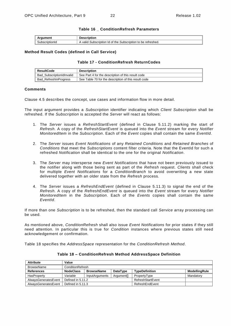
OPC Unified Architecture, Part 9 22 Release 1.02
Table 16 _ ConditionRefresh Parameters
Argument Description
SubscriptionId A valid Subscription Id of the Subscription to be refreshed.
Method Result Codes (defined in Call Service)
Table 17 - ConditionRefresh ReturnCodes
ResultCode Description
Bad_SubscriptionIdInvalid See Part 4 for the description of this result code
Bad_RefreshInProgress See Table 70 for the description of this result code
Comments
Clause 4.5 describes the concept, use cases and information flow in more detail.
The input argument provides a Subscription identifier indicating which Client Subscription shall be refreshed. If the Subscription is accepted the Server will react as follows:
1. The Server issues a RefreshStartEvent (defined in Clause 5.11.2) marking the start of Refresh. A copy of the RefreshStartEvent is queued into the Event stream for every Notifier MonitoredItem in the Subscription. Each of the Event copies shall contain the same EventId.
2. The Server issues Event Notifications of any Retained Conditions and Retained Branches of Conditions that meet the Subscriptions content filter criteria. Note that the EventId for such a refreshed Notification shall be identical to the one for the original Notification.
3. The Server may intersperse new Event Notifications that have not been previously issued to the notifier along with those being sent as part of the Refresh request. Clients shall check for multiple Event Notifications for a ConditionBranch to avoid overwriting a new state delivered together with an older state from the Refresh process.
4. The Server issues a RefreshEndEvent (defined in Clause 5.11.3) to signal the end of the Refresh. A copy of the RefreshEndEvent is queued into the Event stream for every Notifier MonitoredItem in the Subscription. Each of the Events copies shall contain the same EventId.
If more than one Subscription is to be refreshed, then the standard call Service array processing can
be used.
As mentioned above, ConditionRefresh shall also issue Event Notifications for prior states if they still need attention. In particular this is true for Condition instances where previous states still need acknowledgement or confirmation.
Table 18 specifies the AddressSpace representation for the ConditionRefresh Method.
Table 18 – ConditionRefresh Method AddressSpace Definition
Attribute Value
BrowseName ConditionRefresh
References NodeClass BrowseName DataType TypeDefinition ModellingRule
HasProperty Variable InputArguments Argument[] PropertyType Mandatory
AlwaysGeneratesEvent Defined in 5.11.2 RefreshStartEvent
AlwaysGeneratesEvent Defined in 5.11.3 RefreshEndEvent

Release 1.02 23 OPC Unified Architecture, Part 9
5.6 Dialog Model
5.6.1 General
The Dialog Model is an extension of the Condition model used by a Server to request user input. It provides functionality similar to the standard Message dialogs found in most operating systems. The model can easily be customized by providing Server specific response options in the ResponseOptionSet and by adding additional functionality to derived Condition Types.
5.6.2 DialogConditionType
The DialogConditionType is used to represent Conditions as dialogs. It is illustrated in Figure 9 and
formally defined in Table 19.
LastResponse
DialogConditionType
ResponseOptionSet
TwoStateVariableType:
DialogStateRespond
OkResponse
ConditionType
EnableState
IsTrueSubState
Prompt
DefaultResponse CancelResponse
Figure 9 - DialogConditionType Overview
Table 19 – DialogConditionType Definition
Attribute Value
BrowseName DialogConditionType
IsAbstract False
References NodeClass BrowseName DataType TypeDefinition Modelling Rule
Subtype of the ConditionType defined in clause 5.5.2
HasComponent Variable DialogState LocalizedText TwoStateVariableType Mandatory
HasProperty Variable Prompt LocalizedText PropertyType Mandatory
HasProperty Variable ResponseOptionSet LocalizedText [ ] PropertyType Mandatory
HasProperty Variable DefaultResponse Int32 PropertyType Mandatory
HasProperty Variable LastResponse Int32 PropertyType Mandatory
HasProperty Variable OkResponse Int32 PropertyType Mandatory
HasProperty Variable CancelResponse Int32 PropertyType Mandatory
HasComponent Method Respond Defined in Clause 5.6.3. Mandatory
The DialogConditionType inherits all Properties of the ConditionType.
DialogState/Id when set to TRUE indicates that the Dialog is active and waiting for a response. Recommended state names are described in Annex A.
Prompt is a dialog prompt to be shown to the user.
ResponseOptionSet specifies the desired set of responses as array of LocalizedText. The index in this array is used for the corresponding fields like DefaultResponse, LastResponse and SelectedOption in the Respond Method. The recommended localized names for the common options are described in Annex A.

OPC Unified Architecture, Part 9 24 Release 1.02
Typical combinations of response options are
OK
OK, Cancel
Yes, No, Cancel
Abort, Retry, Ignore
Retry, Cancel
Yes, No
DefaultResponse identifies the response option that should be shown as default to the user. It is the index in the ResponseOptionSet array. If no response option is the default, the value of the Property
is -1.
LastResponse contains the last response provided by a Client in the Respond Method. If no previous response exists then the value of the Property is -1.
OkResponse provides the index of the OK option in the ResponseOptionSet array. This choice is the response that will allow the system to proceed with the operation described by the prompt. This allows a Client to identify the OK option if a special handling for this option is available. If no OK option is available the value of this Property is -1.
CancelResponse provides the index of the response in the ResponseOptionSet array that will cause the Dialog to go into the inactive state without proceeding with the operation described by the prompt. This allows a Client to identify the Cancel option if a special handling for this option is available. If no Cancel option is available the value of this Property is -1.
5.6.3 Respond Method
Respond is used to pass the selected response option and end the dialog. DialogState/Id will return to FALSE.
Signature
Respond(
[in] Int32 SelectedResponse
);
Table 20 - Repond Parameters
Argument Description
SelectedResponse Selected index of the ResponseOptionSet array.
Method Result Codes (defined in Call Service)
Table 21 - Respond ResultCodes
ResultCode Description
Bad_DialogNotActive See Table 70 for the description of this result code.
Bad_DialogResponseInvalid See Table 70 for the description of this result code.
Table 22 specifies the AddressSpace representation for the Respond Method.

Release 1.02 25 OPC Unified Architecture, Part 9
Table 22 – Respond Method AddressSpace Definition
Attribute Value
BrowseName Respond
References NodeClass BrowseName DataType TypeDefinition ModellingRule
HasProperty Variable InputArguments Argument[] PropertyType Mandatory
AlwaysGeneratesEvent Defined in 5.10.5 AuditConditionRespondEventType

OPC Unified Architecture, Part 9 26 Release 1.02
5.7 Acknowledgeable Condition Model
5.7.1 General
The Acknowledgeable Condition Model extends the Condition model. States for acknowledgement and confirmation are added to the Condition model.
AcknowledgeableConditions are represented by the AcknowledgeableConditionType which is a subtype of the ConditionType. The model is formally defined in the following sub clauses.
5.7.2 AcknowledgeableConditionType
The AcknowledgeableConditionType extends the ConditionType by defining acknowledgement characteristics. It is an abstract type. The AcknowledgeableConditionType is illustrated in Figure 10
and formally defined in Table 23.
Acknowledgeable
ConditionType
AcknowledgeTwoStateVariableType:
AckedState
TwoStateVariableType:
ConfirmedState
Confirm
ConditionType
EnableState
HasTrueSubState
Figure 10 - AcknowledgeableConditionType Overview
Table 23 – AcknowledgeableConditionType Definition
Attribute Value
BrowseName AcknowledgeableConditionType
IsAbstract False
References NodeClass BrowseName DataType TypeDefinition ModellingRule
Subtype of the ConditionType defined in clause 5.5.2.
HasSubtype ObjectType AlarmConditionType Defined in Clause 5.8.2
HasComponent Variable AckedState LocalizedText TwoStateVariableType Mandatory
HasComponent Variable ConfirmedState LocalizedText TwoStateVariableType Optional
HasComponent Method Acknowledge Defined in Clause 5.7.3 Mandatory
HasComponent Method Confirm Defined in Clause 5.7.4 Optional
The AcknowledgeableConditionType inherits all Properties of the ConditionType.
AckedState when FALSE indicates that the Condition instance requires acknowledgement for the reported Condition state. When the Condition instance is acknowledged the AckedState is set to TRUE. ConfirmedState indicates whether it requires confirmation. Recommended state names are described in Annex A. The two states are sub-states of the TRUE EnabledState. See Clause 4.3 for more information about acknowledgement and confirmation models. The EventId used in the Event Notification is considered the identifier of this state and has to be used when calling the Methods for
acknowledgement or confirmation.

Release 1.02 27 OPC Unified Architecture, Part 9
A Server may require that previous states be acknowledged. If the acknowledgement of a previous state is still open and a new state also requires acknowledgement, the Server shall create a branch of the Condition instance as specified in Clause 4.4. Clients are expected to keep track of all ConditionBranches where AckedState/Id is FALSE to allow acknowledgement of those. See also Clause 5.5.2 for more information about ConditionBranches and the examples in Annex B.1. The handling of the AckedState and branches also applies to the ConfirmState.
5.7.3 Acknowledge Method
Acknowledge is used to acknowledge an Event Notification for a Condition instance state where AckedState was set to FALSE. Normally, the MethodId passed to the Call Service is found by browsing the Condition instance in the AddressSpace. However, some Servers do not expose Condition instances in the AddressSpace. Therefore all Servers shall allow Clients to call the Acknowledge Method by specifying ConditionId as the ObjectId and the well known NodeId of the Method declaration on the AcknowledgeableConditionType as the MethodId. The Method cannot be called on the AcknowledgeableConditionType Node.
Signature
Acknowledge(
[in] ByteString EventId
[in] LocalizedText Comment
);
Table 24 - Acknowledge Parameters
Argument Description
EventId EventId identifying a particular Event Notification.
Only Event Notifications where AckedState/Id was FALSE can be acknowledged.
Comment A localized text to be applied to the Condition.
Method Result Codes (defined in Call Service)
Table 25 Acknowledge result codes
ResultCode Description
Bad_ConditionBranchAlreadyAcked See Table 70 for the description of this result code.
Bad_EventIdUnknown See Table 70 for the description of this result code.
Bad_NodeIdUnknown See Part 4 for the description of this result code.
Used to indicate that the specified Condition is not valid or that the Method was called on the ConditionType Node.
Comments
A Server is responsible to ensure that each Event has a unique EventId. This allows Clients to identify and acknowledge a particular Event Notification.
The EventId identifies a specific Event Notification where a state to be acknowledged was reported. Acknowledgement and the optional comment will be applied to the state ident ified with the EventId. If the comment field is NULL (both locale and text are empty) it will be ignored and any existing comments will remain unchanged. If the comment is to be reset, an empty text with a locale shall be provided.

OPC Unified Architecture, Part 9 28 Release 1.02
A valid EventId will result in an Event Notification where AckedState/Id is set to TRUE and the Comment Property contains the text of the optional comment argument. If a previous state is acknowledged, the BranchId and all Condition values of this branch will be reported. Table 26 specifies the AddressSpace representation for the Acknowledge Method.
Table 26 – Acknowledge Method AddressSpace Definition
Attribute Value
BrowseName Acknowledge
References NodeClass BrowseName DataType TypeDefinition ModellingRule
HasProperty Variable InputArguments Argument[] PropertyType Mandatory
AlwaysGeneratesEvent Defined in 5.10.5 AuditConditionAcknowledge EventType
5.7.4 Confirm Method
Confirm is used to confirm an Event Notifications for a Condition instance state where ConfirmedState was set to FALSE. Normally, the MethodId passed to the Call Service is found by browsing the Condition instance in the AddressSpace. However, some Servers do not expose Condition instances in the AddressSpace. Therefore all Servers shall allow Clients to call the Confirm Method by specifying ConditionId as the ObjectId and the well known NodeId of the Method declaration on the AcknowledgeableConditionType as the MethodId. The Method cannot be called on the AcknowledgeableConditionType Node.
Signature
Confirm(
[in] ByteString EventId
[in] LocalizedText Comment
);
Table 27 – Confirm Method Parameters
Argument Description
EventId EventId identifying a particular Event Notification.
Only Event Notifications where ConfirmedState/Id was TRUE can be confirmed.
Comment A localized text to be applied to the Conditions.
Method Result Codes (defined in Call Service)
Table 28 - Confirm Result Codes
ResultCode Description
Bad_ConditionBranchAlreadyConfirmed See Table 70 for the description of this result code.
Bad_EventIdUnknown See Table 70 for the description of this result code.
Bad_NodeIdUnknown See Part 4 for the description of this result code.
Used to indicate that the specified Condition is not valid or that the Method was called on the ConditionType Node.
Comments
A Server is responsible to ensure that each Event has a unique EventId. This allows Clients to identify and confirm a particular Event Notification.
The EventId identifies a specific Event Notification where a state to be confirmed was reported. A Comment can be provided which will be applied to the state identified with the EventId.
A valid EventId will result in an Event Notification where ConfirmedState/Id is set to TRUE and the Comment Property contains the text of the optional comment argument. If a previous state is confirmed, the BranchId and all Condition values of this branch will be reported.

Release 1.02 29 OPC Unified Architecture, Part 9
Table 29 specifies the AddressSpace representation for the Confirm Method.
Table 29 – Confirm Method AddressSpace Definition
Attribute Value
BrowseName Confirm
References NodeClass BrowseName DataType TypeDefinition ModellingRule
HasProperty Variable InputArguments Argument[] PropertyType Mandatory
AlwaysGeneratesEvent Defined in 5.10.7 AuditConditionConfirm EventType
5.8 Alarm Model
5.8.1 General
Figure 11 informally describes the AlarmConditionType, its sub-types and where it is in the hierarchy of Event Types.
AlarmConditionType
AcknowledgeableConditionType
ConditionType
ExclusiveLimitAlarmType
ExclusiveLevel
ExclusiveMultiDeviation
ExclusiveRateOfChange
NonExclusiveLimitAlarmType
NonExclusiveLevel
NonExclusiveMultiDeviation
NonExclusiveRateOfChange
OffNormalAlarmType
DiscreteAlarmType
TripAlarmType
LimitAlarmType
Figure 11 – AlarmConditionType Hierarchy Model
5.8.2 AlarmConditionType
The AlarmConditionType is an abstract type that extends the AcknowledgeableConditionType by introducing an ActiveState, SuppressedState and ShelvingState. The Alarm model is illustrated in Figure 12. This illustration is not intended to be a complete definition. It is formally defined in Table 30.

OPC Unified Architecture, Part 9 30 Release 1.02
AcknowledgeableConditionType
TwoStateVariableType:
ActiveState
TwoStateVariableType:
SuppressedState
ConditionType
EnableState
IsTrueSubState
AlarmConditionType
StateMachineType:
ShelvingStateCurrentState
Figure 12 - Alarm Model
Table 30 – AlarmConditionType Definition
Attribute Value
BrowseName AlarmConditionType
IsAbstract False
References NodeClass BrowseName DataType TypeDefinition Modelling Rule
Subtype of the AcknowledgeableConditionType defined in clause 5.7.2
HasComponent Variable ActiveState LocalizedText TwoStateVariableType Mandatory
HasProperty Variable InputNode NodeId PropertyType Mandatory
HasComponent Variable SuppressedState LocalizedText TwoStateVariableType Optional
HasComponent Object ShelvingState ShelvedStateMachineType Optional
HasProperty Variable SuppressedOrShelved Boolean PropertyType Mandatory
HasProperty Variable MaxTimeShelved Duration PropertyType Optional
The AlarmConditionType inherits all Properties of the AcknowledgeableConditionType. The following states are sub-states of the TRUE EnabledState.
ActiveState/Id when set to TRUE indicates that the situation the Condition is representing currently exists. When a Condition instance is in the inactive state (ActiveState/Id when set to FALSE) it is representing a situation that has returned to a normal state. The transitions of Conditions to the inactive and Active states are triggered by Server specific actions. Sub-Types of the AlarmConditionType specified later in this document will have sub-state models that further define the Active state. Recommended state names are described in Annex A.
The InputNode Property provides the NodeId of the Variable the Value of which is used as primary input in the calculation of the Alarm state. If this Variable is not in the AddressSpace, a Null NodeId shall be provided. In some systems, an Alarm may be calculated based on multiple Variables Values, it is up to the system to determine which Variable’s NodeId is used.
SuppressState is used internally by a Server to automatically suppress Alarms due to system specific reasons. For example a system may be configured to suppress Alarms that are associated with machinery that is shutdown, such as a low level Alarm for a tank that is currently not in use. Recommended state names are described in Annex A.
ShelvingState suggests whether an Alarm shall (temporarily) be prevented from being displayed to the user. It is quite often used to block nuisance Alarms. The ShelvingState is defined in the
following Clause.

Release 1.02 31 OPC Unified Architecture, Part 9
The SuppressedState and the ShelvingState together result in the SuppressedOrShelved status of the Condition. When an Alarm is in one of the states, the SuppressedOrShelved property will be set TRUE and this Alarm is then typically not displayed by the Client. State transitions associated with the Alarm do occur, but they are not typically displayed by the Clients as long as the Alarm remains in either the Suppressed or Shelved state.
The optional Property MaxTimeShelved is used to set the maximum time that an Alarm Condition may be shelved. The value is expressed as duration. Systems can use this Property to prevent permanent Shelving of an Alarm. If this Property is present it will be an upper limit on the duration passed into a TimedShelve Method call. If a value that exceeds the value of this property is passed to the TimedShelve Method, than a Bad_ShelvingTimeOutOfRange error code is returned on the call. If this Property is present it will also be enforced for the OneShotShelved state, in that a Alarm Condition will transition to the Unshelved state from the OneShotShelved state if the duration specified in this Property expires following a OneShotShelve operation without a change of any of the other items associated with the Condition.
More details about the Alarm Model and the various states can be found in Clause 4.8.
5.8.2.1 ShelvedStateMachineType
The ShelvedStateMachineType defines a sub-state machine that represents an advanced Alarm filtering model. This model is illustrated in Figure 14.
The state model supports two types of Shelving: OneShotShelving and TimedShelving. They are illustrated in Figure 13. The illustration includes the allowed transitions between the various sub -states. Shelving is an Operator initiated activity.
In OneShotShelving, a user requests that an Alarm be Shelved for its current Active state. This type of Shelving is typically used when an Alarm is continually occurring on a boundary (i.e. a Condition is jumping between High Alarm and HighHigh Alarm, always in the Active state). The One Shot Shelving will automatically clear when an Alarm returns to an inactive state. Another use for this type of Shelving is for a plant area that is shutdown i.e. a long running Alarm such as a low level Alarm for a tank that is not in use. When the tank starts operation again the Shelving state will
automatically clear.
In TimedShelving, a user specifies that an Alarm be shelved for a fixed time period. This type of Shelving is quite often used to block nuisance Alarms. For example, an Alarm that occurs more than
10 times in a minute may get shelved for a few minutes.
In all states, the Unshelve can be called to cause a transition to the Unshelve state; this includes Un-shelving an Alarm that is in the TimedShelve state before the time has expired and the OneShotShelve state without a transition to an inactive state.
All but two transitions are caused by Method calls as illustrated in Figure 13. The “Time Expired” transition is simply a system generated transition that occurs when the time value defined as part of the “Timed Shelved Call” has expired. The “Any Transition Occurs” transition is also a system generated transition; this transition is generated when the Condition goes to an inactive state.

OPC Unified Architecture, Part 9 32 Release 1.02
Timed
Shelved
Oneshot
Shelved
Unshelved
Timed Shelve call
Any Transition Occurs
One Shot Shelve callTime Expired
UnShelve callUnShelve call
Timed Shelve call
One Shot Shelve call
Figure 13 - Shelve state transitions
The ShelvedStateMachine includes a hierarchy of sub-states. It supports all transitions between Unshelved, OneShotShelved and TimedShelved.
The state machine is illustrated in Figure 14 and formally defined in Table 31.
OneShotShelve
ShelvedStateMachine
Type
TimedShelved
OneShotShelved
UnShelvedToTimedShelved
HasCause
FiniteStateMachineType
Unshelved
UnShelvedToOneShotShelved
TimedShelvedToUnshelved
OneShotShelvedToUnShelved
Unshelve
HasCause
HasCause
TimedShelve
HasCause
TimedShelvedToOneShotShelved
HasCauseOneShotShelvedToTimedShelved
HasCause
StateType
TransitionType
UnshelveTime
Figure 14 - Shelved State Machine Model

Release 1.02 33 OPC Unified Architecture, Part 9
Table 31 –ShelvedStateMachine Definition
Attribute Value
BrowseName ShelvedStateMachineType
IsAbstract False
References NodeClass BrowseName DataType TypeDefinition ModellingRule
Subtype of the FiniteStateMachineType defined in Part 5
HasProperty Variable UnshelveTime Duration PropertyType Mandatory
HasComponent Object Unshelved StateType Mandatory
HasComponent Object TimedShelved StateType Mandatory
HasComponent Object OneShotShelved StateType Mandatory
HasComponent Object UnshelvedToTimedShelved TransitionType Mandatory
HasComponent Object TimedShelvedToUnshelved TransitionType Mandatory
HasComponent Object TimedShelvedToOneShotShelved TransitionType Mandatory
HasComponent Object UnshelvedToOneShotShelved TransitionType Mandatory
HasComponent Object OneShotShelvedToUnshelved TransitionType Mandatory
HasComponent Object OneShotShelvedToTimedShelved TransitionType Mandatory
HasComponent Method TimedShelve Defined in Clause 5.8.2.3 Mandatory
HasComponent Method OneShotShelve Defined in Clause 5.8.2.4 Mandatory
HasComponent Method Unshelve Defined in Clause 5.8.2.2 Mandatory
UnshelveTime specifies the remaining time in milliseconds until the Alarm automatically transitions into the Un-shelved state. For the TimedShelved state this time is initialised with the ShelvingTime argument of the TimedShelve Method call. For the OneShotShelved state the UnshelveTime will be a constant set to the maximum Duration except if a MaxTimeShelved Property is provided
This FiniteStateMachine supports three Active states; Unshelved, TimedShelved and OneShotShelved. It also supports six transitions. The states and transitions are described in Table 32. This FiniteStateMachine also supports three Methods; TimedShelve, OneShotShelve and UnShelve.
Table 32 – ShelvedStateMachine Transitions
BrowseName References BrowseName Value TypeDefinition Notes
Transitions
UnshelvedToTimedShelved FromState Unshelved StateType
ToState TimedShelved StateType
HasEffect AlarmConditionType
HasCause TimedShelve Method
UnshelvedToOneShotShelved FromState Unshelved StateType
ToState OneShotShelved StateType
HasEffect AlarmConditionType
HasCause OneShotShelve Method
TimedShelvedToUnshelved FromState TimedShelved StateType
ToState Unshelved StateType
HasEffect AlarmConditionType
TimedShelvedToOneShotShelved FromState TimedShelved StateType
ToState OneShotShelved StateType
HasEffect AlarmConditionType
HasCause OneShotShelving Method
OneShotShelvedToUnshelved FromState OneShotShelved StateType
ToState Unshelved StateType
HasEffect AlarmConditionType
OneShotShelvedToTimedShelved FromState OneShotShelved StateType
ToState TimedShelved StateType
HasEffect AlarmConditionType
HasCause TimedShelve Method

OPC Unified Architecture, Part 9 34 Release 1.02
5.8.2.2 Unshelve Method
Unshelve sets the AlarmCondition to the Unshelved state.
Signature
Unshelve( );
Method Result Codes (defined in Call Service)
Table 33 - Unshelve Result Codes
ResultCode Description
Bad_ConditionNotShelved See Table 70 for the description of this result code.
Table 34 specifies the AddressSpace representation for the Unshelve Method.
Table 34 – Unshelve Method AddressSpace Definition
Attribute Value
BrowseName Unshelve
References NodeClass BrowseName DataType TypeDefinition ModellingRule
AlwaysGeneratesEvent Defined in 5.10.7 AuditConditionShelvingEventType
5.8.2.3 TimedShelve Method
TimedShelve sets the AlarmCondition to the TimedShelved state (Parameters are defined in Table
35 and result code are described in Table 36).
Signature
TimedShelve(
[in] Duration ShelvingTime
);
Table 35 - TimedShelve Parameters
Argument Description
ShelvingTime Specifies a fixed time for which the Alarm is to be shelved. The Server may refuse the provided duration. If a MaxTimeShelved Property exist on the Alarm than the Shelving time shall be less than or equal to the value of this Property.
Method Result Codes (defined in Call Service)
Table 36 - TimedShelve Result Codes
ResultCode Description
Bad_ConditionAlreadyShelved See Table 70 for the description of this result code.
The Alarm is already in TimedShelved state and the system does not allow a reset of the shelved timer.
Bad_ShelvingTimeOutOfRange See Table 70 for the description of this result code.
Comments
Shelving for some time is quite often used to block nuisance Alarms. For example, an Alarm that occurs more than 10 times in a minute may get shelved for a few minutes.
In some systems the length of time covered by this duration may be limited and the Server may generate an error refusing the provided duration. This limit may be exposed as the MaxTimeShelved Property.

Release 1.02 35 OPC Unified Architecture, Part 9
Table 37 specifies the AddressSpace representation for the TimedShelve Method.
Table 37 – TimedShelve Method AddressSpace Definition
Attribute Value
BrowseName TimedShelve
References NodeClass BrowseName DataType TypeDefinition ModellingRule
HasProperty Variable InputArguments Argument[] PropertyType Mandatory
AlwaysGeneratesEvent
Defined in 5.10.7 AuditConditionShelvingEventType
5.8.2.4 OneShotShelve Method
OneShotShelve sets the AlarmCondition to the OneShotShelved state.
Signature
OneShotShelve( );
Method Result Codes (defined in Call Service)
Table 38 - OneShotShelve Result Codes
ResultCode Description
Bad_AlreadyShelved See Table 70 for the description of this result code.
The Alarm is already in OneShotShelved state.
Table 39 specifies the AddressSpace representation for the OneShotShelve Method.
Table 39 – OneShotShelve Method AddressSpace Definition
Attribute Value
BrowseName OneShotShelve
References NodeClass BrowseName DataType TypeDefinition ModellingRule
AlwaysGeneratesEvent Defined in 5.10.7 AuditConditionShelvingEventType
5.8.3 LimitAlarmType
Alarms can be modelled with multiple exclusive sub-states and assigned limits or they may be modelled with non exclusive limits that can be used to group multiple states together.

OPC Unified Architecture, Part 9 36 Release 1.02
The LimitAlarmType is an abstract type used to provide a base Type for AlarmConditions with multiple limits. The LimitAlarmType is illustrated in Figure 15.
AlarmConditionType
LimitAlarmType
LowLimit
LowLowLimit
HighLimit
HighHighLimit
ExclusiveLimit
AlarmTypeNonExclusiveLimit
AlarmType
Figure 15 - LimitAlarmType
The LimitAlarmType is formally defined in Table 40.
Table 40 –LimitAlarmType Definition
Attribute Value
BrowseName LimitAlarmType
IsAbstract False
References NodeClass BrowseName DataType TypeDefinition Modelling Rule
Subtype of the AlarmConditionType defined in clause 5.8.2.
HasSubtype ObjectType ExclusiveLimitAlarmType Defined in Clause 5.8.4.3
HasSubtype ObjectType NonExclusiveLimitAlarmType Defined in Clause 5.8.5
HasProperty Variable HighHighLimit Double PropertyType Optional
HasProperty Variable HighLimit Double PropertyType Optional
HasProperty Variable LowLimit Double PropertyType Optional
HasProperty Variable LowLowLimit Double PropertyType Optional
Four optional limits are defined that configure the states of the derived limit Alarm Types. These Properties shall be set for any Alarm limits that are exposed by the derived limit Alarm Types. These Properties are listed as optional but at least one is required. For cases where an underlying system cannot provide the actual value of a limit, the limit Property shall still be provided, but will have its AccessLevel set to not readable.
The Alarm limits listed may cause an Alarm to be generate when a value equals the limit or it may generate the Alarm when the limit is exceeded, (i.e. the Value is above the limit for HighLimit and below the limit for LowLimit). The exact behaviour when the value is equal to the limit is Server
specific.
5.8.4 ExclusiveLimit Types
5.8.4.1 Overview
This Clause describes the state machine and the base Alarm Type behaviour for Alarm Types with
multiple mutually exclusive limits.

Release 1.02 37 OPC Unified Architecture, Part 9
5.8.4.2 ExclusiveLimitStateMachineType
The ExclusiveLimitStateMachineType defines the state machine used by AlarmTypes that handle
multiple mutually exclusive limits. It is illustrated in Figure 16.
FiniteStateMachineType
Low
High
ExclusiveLimit
StateMachineType
LowLow
HighHigh
HighHighToHigh
HighToHighHigh
LowToLowLow
LowLowToLow
StateType
TransitionType
Figure 16 - ExclusiveLimitStateMachine
It is created by extending the FiniteStateMachineType. It is formally defined in Table 41 and the
state transitions are described in Table 42.
Table 41 – ExclusiveLimitStateMachineType Definition
Attribute Value
BrowseName ExclusiveLimitStateMachineType
IsAbstract False
References NodeClass BrowseName DataType TypeDefinition ModellingRule
Subtype of the FiniteStateMachineType
HasComponent Object HighHigh StateType Optional
HasComponent Object High StateType Optional
HasComponent Object Low StateType Optional
HasComponent Object LowLow StateType Optional
HasComponent Object LowToLowLow TransitionType Optional
HasComponent Object LowLowToLow TransitionType Optional
HasComponent Object HighToHighHigh TransitionType Optional
HasComponent Object HighHighToHigh TransitionType Optional

OPC Unified Architecture, Part 9 38 Release 1.02
Table 42 – ExclusiveLimitStateMachineType Transitions
BrowseName References BrowseName Value TypeDefinition Notes
Transitions
HighHighToHigh FromState HighHigh StateType
ToState High StateType
HasEffect AlarmConditionType
HighToHighHigh FromState High StateType
ToState HighHigh StateType
HasEffect AlarmConditionType
LowLowToLow FromState LowLow StateType
ToState Low StateType
HasEffect AlarmConditionType
LowToLowLow FromState Low StateType
ToState LowLow StateType
HasEffect AlarmConditionType
The ExclusiveLimitStateMachine defines the sub state machine that represents the actual level of a multilevel Alarm when it is in the Active state. The sub state machine defined here includes High, Low, HighHigh and LowLow states. This model also includes in its transition state a series of transition to and from a parent state, the inactive state. This state machine as it is defined shall be used as a sub state machine for a state machine which has an Active state. This Active state could be part of a “level” Alarm or “deviation” Alarm or any other Alarm state machine.
The LowLow, Low, High, HighHigh are typical for many industries. Vendors can introduce sub -state models that include additional limits; they may also omit limits in an instance.

Release 1.02 39 OPC Unified Architecture, Part 9
5.8.4.3 ExclusiveLimitAlarmType
The ExclusiveLimitAlarmType is used to specify the common behaviour for Alarm Types with multiple mutually exclusive limits. The ExclusiveLimitAlarmType is illustrated in Figure 17.
ConditionType
AcknowledgeableConditionType
AlarmConditionType
ExclusiveLimit AlarmType
ActiveState
EnableState
IsTrueSubState
LowLimit
LowLowLimit
HighLimit
HighHighLimit
ExclusiveLimitStateMachineType:
LimitState
CurrentState
IsTrueSubState
ExclusiveLevel
AlarmTypeExclusiveDeviation
AlarmType
ExclusiveRateOfChange
AlarmType
LimitAlarmType
Figure 17 - ExclusiveLimitAlarmType
The ExclusiveLimitAlarmType is formally defined in Table 43.
Table 43 – ExclusiveLimitAlarmType Definition
Attribute Value
BrowseName ExclusiveLimitAlarmType
IsAbstract False
References NodeClass BrowseName DataType TypeDefinition Modelling Rule
Subtype of the LimitAlarmType defined in clause 5.8.3.
HasSubtype ObjectType ExclusiveLevelAlarmType Defined in Clause 5.8.6.3
HasSubtype ObjectType ExclusiveDeviationAlarm Type Defined in Clause 5.8.7.3
HasSubtype ObjectType ExclusiveRateOfChange AlarmType
Defined in Clause 5.8.8.3
HasComponent Object LimitState ExclusiveLimitStateMachineType Mandatory
The LimitState is a Substate of the ActiveState and has a IsTrueSubstate reference to the ActiveState. The LimitState represents the actual limit that is violated in an ExclusiveLimitAlarm. When the ActiveState of the AlarmConditionType is inactive the LimitState shall not be available and shall return NULL on read. Any Events that subscribe for fields from the LimitState when the ActiveState is inactive shall return a NULL for these unavailable fields

OPC Unified Architecture, Part 9 40 Release 1.02
5.8.5 NonExclusiveLimitAlarmType
The NonExclusiveLimitAlarmType is used to specify the common behaviour for Alarm Types with multiple non-exclusive limits. The NonExclusiveLimitAlarmType is illustrated in Figure 18.
ConditionType
AcknowledgeableConditionType
AlarmConditionType
NonExclusiveLimit AlarmType
ActiveState
EnableState
IsTrueSubState
IsTrueSubState
NonExclusiveLevel
AlarmType
NonExclusiveDeviation
AlarmTypeNonExclusiveRateOfChange
AlarmType
HighHighState
HighState
LowState
LowLowState
LimitAlarmType
LowLimit
LowLowLimit
HighLimit
HighHighLimit
Figure 18 - NonExclusiveLimitAlarmType
The NonExclusiveLimitAlarmType is formally defined in Table 44.
Table 44 – NonExclusiveLimitAlarmType Definition
Attribute Value
BrowseName NonExclusiveLimitAlarmType
IsAbstract False
References NodeClass BrowseName DataType TypeDefinition Modelling Rule
Subtype of the LimitAlarmType defined in clause 5.8.3.
HasSubtype ObjectType NonExclusiveLevelAlarmType Defined in Clause 5.8.6.2
HasSubtype ObjectType NonExclusiveDeviationAlarmType Defined in Clause 5.8.7.2
HasSubtype ObjectType NonExclusiveRateOfChange AlarmType
Defined in Clause 5.8.8.2
HasComponent Variable HighHighState LocalizedText TwoStateVariableType Optional
HasComponent Variable HighState LocalizedText TwoStateVariableType Optional
HasComponent Variable LowState LocalizedText TwoStateVariableType Optional
HasComponent Variable LowLowState LocalizedText TwoStateVariableType Optional

Release 1.02 41 OPC Unified Architecture, Part 9
HighHighState, HighState, LowState, and LowLowState represent the non-exclusive states. As an example, it is possible that both HighState and HighHighState are in their TRUE state. Vendors may choose to support any subset of these states. Recommended state names are described in Annex A.
Four optional limits are defined that configure these states. At least the HighState or the LowState shall be provided even though all states are optional. It is implied by the definition of a HighState and a LowState, that these groupings are mutually exclusive. A value cannot exceed both a HighState value and a LowState value simultaneously.
5.8.6 Level Alarm
5.8.6.1 Overview
A level Alarm is commonly used to report when a limit is exceeded. It typically relates to an instrument – e.g. a temperature meter. The level Alarm becomes active when the observed value is
above a high limit or below a low limit.
5.8.6.2 NonExclusiveLevelAlarmType
The NonExclusiveLevelAlarmType is a special level Alarm utilized with one or more non-exclusive states. If for example both the High and HighHigh states need to be maintained as active at the same time this AlarmType should be used.
The NonExclusiveLevelAlarmType is based on the NonExclusiveLimitAlarmType. It is formally
defined in Table 45.
Table 45 – NonExclusiveLevelAlarmType Definition
Attribute Value
BrowseName NonExclusiveLevelAlarmType
IsAbstract False
References NodeClass BrowseName DataType TypeDefinition ModellingRule
Subtype of the NonExclusiveLimitAlarmType defined in clause 5.8.5.
No additional Properties to the NonExclusiveLimitAlarmType are defined.
5.8.6.3 ExclusiveLevelAlarmType
The ExclusiveLevelAlarmType is a special level Alarm utilized with multiple mutually exclusive limits. It is formally defined in Table 46.
Table 46 – ExclusiveLevelAlarmType Definition
Attribute Value
BrowseName ExclusiveLevelAlarmType
IsAbstract False
References NodeClass BrowseName DataType TypeDefinition ModellingRule
Inherits the Properties of the ExclusiveLimitAlarmType defined in clause 5.8.4.3.
No additional Properties to the ExclusiveLimitAlarmType are defined.
5.8.7 Deviation Alarm
5.8.7.1 Overview
A deviation Alarm is commonly used to report an excess deviation between a desired set point level of a process value and an actual measurement of that value. The deviation Alarm becomes active
when the deviation exceeds or drops below a defined limit.

OPC Unified Architecture, Part 9 42 Release 1.02
For example if a set point had a value of 10 and the high deviation Alarm limit were set for 2 and the low deviation Alarm limit had a value of -1 then the low sub state is entered if the process value dropped to below 9; the high sub state is entered if the process value became larger than 12. If the set point were changed to 11 then the new deviation values would be 10 and 13 respectively.
5.8.7.2 NonExclusiveDeviationAlarmType
The NonExclusiveDeviationAlarmType is a special level Alarm utilized with one or more non-exclusive states. If for example both the High and HighHigh states need t o be maintained as active at the same time this AlarmType should be used.
The NonExclusiveDeviationAlarmType is based on the NonExclusiveLimitAlarmType. It is formally
defined in Table 47.
Table 47 – NonExclusiveDeviationAlarmType Definition
Attribute Value
BrowseName NonExclusiveDeviationAlarmType
IsAbstract False
References NodeClass BrowseName DataType TypeDefinition ModellingRule
Subtype of the NonExclusiveLimitAlarmType defined in clause 5.8.5.
HasProperty Variable SetpointNode NodeId PropertyType Mandatory
The SetpointNode Property provides the NodeId of the set point used in the deviation calculation. If this Variable is not in the AddressSpace, a Null NodeId shall be provided.
5.8.7.3 ExclusiveDeviationAlarmType
The ExclusiveDeviationAlarmType is utilized with multiple mutually exclusive limits. It is formally
defined in Table 48.
Table 48 – ExclusiveDeviationAlarmType Definition
Attribute Value
BrowseName ExclusiveDeviationAlarmType
IsAbstract False
References NodeClass BrowseName DataType TypeDefinition Modelling Rule
Inherits the Properties of the ExclusiveLimitAlarmType defined in clause 5.8.4.3.
HasProperty Variable SetpointNode NodeId PropertyType Mandatory
The SetpointNode Property provides the NodeId of the set point used in the Deviation calculation. If this Variable is not in the AddressSpace, a Null NodeId shall be provided.
5.8.8 Rate of Change
5.8.8.1 Overview
A Rate of Change Alarm is commonly used to report an unusual change or lack of change in a measured value related to the speed at which the value has changed. The Rate of Change Alarm
becomes active when the rate at which the value changes exceeds or drops below a defined limit.
A Rate of Change is measured in some time unit, such as seconds or minutes and some unit of measure such as percent or meter. For example a tank may have a High limit for the Rate of Change of its level (measured in meters) which would be 4 meters per minute. If the tank level changes at a rate that is greater than 4 meters per minute then the High sub state is entered.

Release 1.02 43 OPC Unified Architecture, Part 9
5.8.8.2 NonExclusiveRateOfChangeAlarmType
The NonExclusiveRateOfChangeAlarmType is a special level Alarm utilized with one or more non-exclusive states. If for example both the High and HighHigh states need to be maintained as active at the same time this AlarmType should be used
The NonExclusiveRateOfChangeAlarmType is based on the NonExclusiveLimitAlarmType. It is formally defined in Table 49.
Table 49 – NonExclusiveRateOfChangeAlarmType Definition
Attribute Value
BrowseName NonExclusiveRateOfChangeAlarmType
IsAbstract False
References NodeClass BrowseName DataType TypeDefinition ModellingRule
Subtype of the NonExclusiveLimitAlarmType defined in clause 5.8.5.
No additional Properties to the NonExclusiveLimitAlarmType are defined.
5.8.8.3 ExclusiveRateOfChangeAlarmType
ExclusiveRateOfChangeAlarmType is utilized with multiple mutually exclusive limits. It is formally
defined in Table 50.
Table 50 – ExclusiveRateOfChangeAlarmType Definition
Attribute Value
BrowseName ExclusiveRateOfChangeAlarmType
IsAbstract False
References NodeClass BrowseName DataType TypeDefinition ModellingRule
Inherits the Properties of the ExclusiveLimitAlarmType defined in clause 5.8.4.3.
No additional Properties to the ExclusiveLimitAlarmType are defined.

OPC Unified Architecture, Part 9 44 Release 1.02
5.8.9 Discrete Alarms
5.8.9.1 DiscreteAlarmType
The DiscreteAlarmType is used to classify Types into Alarm Conditions where the input for the Alarm may take on only a certain number of possible values (e.g. true/false, running /stopped/terminating). The DiscreteAlarmType with sub types defined in this standard is illustrated in Figure 19. It is
formally defined in Table 51.
AlarmConditionType
OffNormalAlarmType
DiscreteAlarmType
TripAlarmType
LimitAlarmType
Figure 19 - DiscreteAlarmType Hierarchy
Table 51 – DiscreteAlarmType Definition
Attribute Value
BrowseName DiscreteAlarmType
IsAbstract False
References NodeClass BrowseName DataType TypeDefinition Modelling Rule
Subtype of the AlarmConditionType defined in clause 5.8.2.
HasSubtype ObjectType OffNormalAlarmType Defined in Clause 5.8.7
5.8.9.2 OffNormalAlarmType
The OffNormalAlarmType is a specialization of the DiscreteAlarmType intended to represent a discrete Condition that is considered to be not normal. It is formally defined in Table 52. This sub type is usually used to indicate that a discrete value is in an Alarm state, it is active as long as a non-normal value is present.
Table 52 – OffNormalAlarmType Definition
Attribute Value
BrowseName OffNormalAlarmType
IsAbstract False
References NodeClass BrowseName DataType TypeDefinition Modelling Rule
Subtype of the DiscreteAlarmType defined in clause 5.8.9.1
HasSubtype ObjectType TripAlarmType Defined in Clause 5.8.9.4
HasProperty Variable NormalState NodeId PropertyType Mandatory
The NormalState Property is a Property that points to a Variable which has a value that corresponds to one of the possible values of the Variable pointed to by the InputNode Property where the NormalState Property Variable value is the value that is considered to be the normal state of the Variable pointed to by the InputNode Property. When the value of the Variable referenced by the InputNode Property is not equal to the value of the NormalState Property the Alarm is Active. If this Variable is not in the AddressSpace, a Null NodeId shall be provided.

Release 1.02 45 OPC Unified Architecture, Part 9
5.8.9.3 SystemOffNormalAlarmType
This Condition is used by a Server to indicate that an underlying system that is providing Alarm information is having a communication problem and that the Server may have invalid or incomplete Condition state in the Subscription. Its representation in the AddressSpace is formally defined in
Table 53.
Table 53 – SystemOffNormalAlarmType Definition
Attribute Value
BrowseName SystemOffNormalAlarmType
IsAbstract True
References NodeClass BrowseName DataType TypeDefinition ModellingRule
Inherit the Properties of the OffNormalAlarmType, i.e. it has HasProperty References to the same Nodes.
5.8.9.4 TripAlarmType
The TripAlarmType is a specialization of the OffNormalAlarmType intended to represent an equipment trip Condition. The Alarm becomes active when the monitored piece of equipment experiences some abnormal fault such as a motor shutting down due to an overload Condition. It is formally defined in Table 54. This Type is mainly used for categorization.
Table 54 – TripAlarmType Definition
Attribute Value
BrowseName TripAlarmType
IsAbstract False
References NodeClass BrowseName DataType TypeDefinition Modelling Rule
Subtype of the OffNormalAlarmType defined in clause 5.8.9.2.
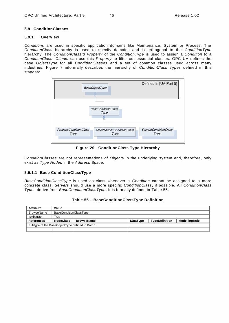
OPC Unified Architecture, Part 9 46 Release 1.02
5.9 ConditionClasses
5.9.1 Overview
Conditions are used in specific application domains like Maintenance, System or Process. The ConditionClass hierarchy is used to specify domains and is orthogonal to the ConditionType hierarchy. The ConditionClassId Property of the ConditionType is used to assign a Condition to a ConditionClass. Clients can use this Property to filter out essential classes. OPC UA defines the base ObjectType for all ConditionClasses and a set of common classes used across many industries. Figure 7 informally describes the hierarchy of ConditionClass Types defined in this
standard.
Defined in [UA Part 5]BaseObjectType
BaseConditionClassType
ProcessConditionClassType
MaintenanceConditionClassType
SystemConditionClassType
Figure 20 - ConditionClass Type Hierarchy
ConditionClasses are not representations of Objects in the underlying system and, therefore, only exist as Type Nodes in the Address Space.
5.9.1.1 Base ConditionClassType
BaseConditionClassType is used as class whenever a Condition cannot be assigned to a more concrete class. Servers should use a more specific ConditionClass, if possible. All ConditionClass Types derive from BaseConditionClassType. It is formally defined in Table 55.
Table 55 – BaseConditionClassType Definition
Attribute Value
BrowseName BaseConditionClassType
IsAbstract True
References NodeClass BrowseName DataType TypeDefinition ModellingRule
Subtype of the BaseObjectType defined in Part 5.

Release 1.02 47 OPC Unified Architecture, Part 9
5.9.1.2 ProcessConditionClassType
The ProcessConditionClassType is used to classify Conditions related to the process itself. Examples of a process would be a control system in a boiler or t he instrumentation associated with a chemical plant or paper machine. The ProcessConditionClassType is formally defined in Table 56.
Table 56 – ProcessConditionClassType Definition
Attribute Value
BrowseName ProcessConditionClassType
IsAbstract True
References NodeClass BrowseName DataType TypeDefinition Modelling Rule
Subtype of the BaseConditionClassType defined in clause 5.9.1.1.
5.9.1.3 MaintenanceConditionClassType
The MaintenanceConditionClassType is used to classify Conditions related to maintenance. Examples of maintenance would be Asset Management systems or conditions, which occur in process control systems, which are related to calibration of equipment. The MaintenanceConditionClassType is formally defined in Table 57. No further definition is provided here. It is expected that other standards groups will define domain -specific sub-types.
Table 57 – MaintenanceConditionClassType Definition
Attribute Value
BrowseName MaintenanceConditionClassType
IsAbstract True
References NodeClass BrowseName DataType TypeDefinition ModellingRule
Subtype of the BaseConditionClassType defined in clause 5.9.1.1.
5.9.1.4 SystemConditionClassType
The SystemConditionClassType is used to classify Conditions related to the System. It is formally defined in Table 58. System Conditions occur in the controlling or monitoring system process. .Examples of System related items could include available disk space on a compute r, Archive media availability, network loading issues or a controller error, No further definition is provided here. It is expected that other standards groups or vendors will define domain-specific sub-types.

OPC Unified Architecture, Part 9 48 Release 1.02
Table 58 – SystemConditionClassType Definition
Attribute Value
BrowseName SystemConditionClassType
IsAbstract True
References NodeClass BrowseName DataType TypeDefinition ModellingRule
Subtype of the BaseConditionClassType defined in clause 5.9.1.1.
5.10 Audit Events
5.10.1 Overview
Following are sub-types of AuditUpdateMethodEventTypes that will be generated in response to the Methods defined in this document. They are illustrated in Figure 21.
Defined in [UA Part 5]AuditEventType
AuditConditionComment EventType
AuditCondition EventType
AuditUpdateMethod EventType
AuditConditionAcknowledge EventType
AuditConditionEnable EventType
AuditConditionShelving EventType
AuditConditionRespond EventType
AuditConditionConfirm EventType
Figure 21 – AuditEvent Hierarchy
Audit Condition EventTypes are normally used in response to a Method call. However, these Events shall also be notified if the functionality of such a Method is performed by some other Server-specific means. In this case the SourceName Property shall contain a proper description of this internal means and the other properties should be filled in as described for the given Event type
5.10.2 AuditConditionEventType
This EventType is used to subsume all Audit Condition EventTypes . It is formally defined in Table
59.
Table 59 – AuditConditionEventType Definition
Attribute Value
BrowseName AuditConditionEventType
IsAbstract False
References NodeClass BrowseName DataType TypeDefinition ModellingRule
Subtype of the AuditUpdateMethodEventType defined in Part 5
Audit Condition EventTypes inherit all Properties of the AuditUpdateMethodEventType defined in Part 5. Unless a subtype overrides the definition, the inherited properties of the Condition will be
used as defined.
The inherited Property SourceNode shall be filled with the ConditionId.

Release 1.02 49 OPC Unified Architecture, Part 9
The SourceName shall be “Method/” and the name of the Service that generated the Event (e.g. Disable, Enable, Acknowledge, etc).
This Event Type can be further customized to reflect particular Condition related actions.
5.10.3 AuditConditionEnableEventType
This EventType is used to indicate a change in the enabled state of a Condition instance. It is formally defined in Table 60.
Table 60 – AuditConditionEnableEventType Definition
Attribute Value
BrowseName AuditConditionEnableEventType
IsAbstract False
References NodeClass BrowseName DataType TypeDefinition ModellingRule
Subtype of the AuditConditionEventType defined in 5.10.2 that is, inheriting the InstanceDeclarations of that Node.
The SourceName shall indicate Method/Enable or Method/Disable. If the audit Event is not the result of a Method call, but due to an internal action of the Server the SourceName shall reflect Enable or Disable, it may be preceded by an appropriate description such as “Internal/Enable” or “Remote/Enable”
5.10.4 AuditConditionCommentEventType
This EventType is used to report an AddComment action. It is formally defined in Table 61.
Table 61 – AuditConditionCommentEventType Definition
Attribute Value
BrowseName AuditConditionCommentEventType
IsAbstract False
References NodeClass BrowseName DataType TypeDefinition ModellingRule
HasProperty Variable EventId ByteString PropertyType Mandatory
HasProperty Variable Comment LocalizedText PropertyType Mandatory
Subtype of the AuditConditionEventType defined in 5.10.2 that is, inheriting the InstanceDeclarations of that Node.
The EventId field shall contain the id of the event for which the comment was added. The Comment contains the actual comment that was added.
5.10.5 AuditConditionRespondEventType
This EventType is used to report a Respond action. It is formally defined in Table 62.
Table 62 – AuditConditionRespondEventType Definition
Attribute Value
BrowseName AuditConditionRespondEventType
IsAbstract False
References NodeClass BrowseName DataType TypeDefinition ModellingRule
HasProperty Variable SelectedResponse Uint32 PropertyType Mandatory
Subtype of the AuditConditionEventType defined in 5.10.2 that is, inheriting the InstanceDeclarations of that Node.
The SelectedResponse field shall contain the response that was selected.

OPC Unified Architecture, Part 9 50 Release 1.02
5.10.6 AuditConditionAcknowledgeEventType
This EventType is used to indicate acknowledgement or confirmation of one or more Conditions. It is
formally defined in Table 63.
Table 63 – AuditConditionAcknowledgeEventType Definition
Attribute Value
BrowseName AuditConditionCommentEventType
IsAbstract False
References NodeClass BrowseName DataType TypeDefinition ModellingRule
HasProperty Variable EventId ByteString PropertyType Mandatory
HasProperty Variable Comment LocalizedText PropertyType Mandatory
Subtype of the AuditConditionEventType defined in 5.10.2 that is, inheriting the InstanceDeclarations of that Node.
The EventId field shall contain the id of the Event that was acknowledged. The Comment contains the actual comment that was added, it may be a blank comment or a null.
5.10.7 AuditConditionConfirmEventType
This EventType is used to report a Confirm action. It is formally defined in Table 64.
Table 64 – AuditConditionConfirmEventType Definition
Attribute Value
BrowseName AuditConditionCommentEventType
IsAbstract False
References NodeClass BrowseName DataType TypeDefinition ModellingRule
HasProperty Variable EventId ByteString PropertyType Mandatory
HasProperty Variable Comment LocalizedText PropertyType Mandatory
Subtype of the AuditConditionEventType defined in 5.10.2 that is, inheriting the InstanceDeclarations of that Node.
The EventId field shall contain the id of the Event that was confirmed. The Comment contains the actual comment that was added, it may be a blank comment or a null.
5.10.8 AuditConditionShelvingEventType
This EventType is used to indicate a change to the Shelving state of a Condition instance. It is
formally defined in Table 65.
Table 65 – AuditConditionShelvingEventType Definition
Attribute Value
BrowseName AuditConditionShelvingEventType
IsAbstract False
References NodeClass BrowseName DataType TypeDefinition ModellingRule
HasProperty Variable ShelvingTime Duration PropertyType Optional
Subtype of the AuditConditionEventType defined in 5.10.2 that is, inheriting the InstanceDeclarations of that Node.
If the Method indicates a TimedShelve operation, the ShelvingTime field shall contain duration for which the Alarm is to be shelved. For other Shelving Methods, this parameter may be omitted or null.
5.11 Condition Refresh Related Events
5.11.1 Overview
Following are sub-types of SystemEventTypes that will be generated in response to a Refresh Methods call. They are illustrated in Figure 22.
Figure 22 – Refresh Related Event Hierarchy

Release 1.02 51 OPC Unified Architecture, Part 9
Defined in [UA Part 5]
RefreshEndEventType
SystemEventType
BaseEventType
RefreshRequired EventType
RefreshStart EventType
5.11.2 RefreshStartEventType
This EventType is used by a Server to mark the beginning of a Refresh Notification cycle. Its representation in the AddressSpace is formally defined in Table 66.
Table 66 – RefreshStartEventType Definition
Attribute Value
BrowseName RefreshStartEventType
IsAbstract True
References NodeClass BrowseName DataType TypeDefinition ModellingRule
Inherit the Properties of the SystemEventType defined in Part 5, i.e. it has HasProperty References to the same Nodes.
5.11.3 RefreshEndEventType
This EventType is used by a Server to mark the end of a Refresh Notification cycle. Its representation in the AddressSpace is formally defined in Table 67.
Table 67 – RefreshEndEventType Definition
Attribute Value
BrowseName RefreshEndEventType
IsAbstract True
References NodeClass BrowseName DataType TypeDefinition ModellingRule
Inherit the Properties of the SystemEventType defined in Part 5, i.e. it has HasProperty References to the same Nodes.
5.11.4 RefreshRequiredEventType
This EventType is used by a Server to indicate that a significant change has occurred in the Server or in the subsystem below the Server that may or does invalidate the Condition state of a Subscription. Its representation in the AddressSpace is formally defined in Table 68.
Table 68 – RefreshRequiredEventType Definition
Attribute Value
BrowseName RefreshRequiredEventType
IsAbstract True
References NodeClass BrowseName DataType TypeDefinition ModellingRule
Inherit the Properties of the SystemEventType defined in Part 5, i.e. it has HasProperty References to the same Nodes.

OPC Unified Architecture, Part 9 52 Release 1.02
When a Server detects an Event queue overflow, it shall track if any Condition Events have been lost, if any Condition Events were lost, it shall issue a RefreshRequiredEventType Event to the Client after the Event queue is no longer in an overflow state.
5.12 HasCondition Reference Type
The HasCondition ReferenceType is a concrete ReferenceType and can be used directly. It is a subtype of NonHierarchicalReferences . The representation in the AddressSpace is specified in Table
69.
The semantic of this ReferenceType is to specify the relationship between a ConditionSource and its Conditions. Each ConditionSource shall be the target of a HasEventSource Reference or a sub type of HasEventSource. The AddressSpace organisation that shall be provided for Clients to detect Conditions and ConditionSources is defined in clause 6. Various examples for the use of this ReferenceType can be found in Annex B.2.
HasCondition References can be used in the Type definition of an Object or a Variable. In this case, the SourceNode of this ReferenceType shall be an ObjectType or VariableType Node or one of their InstanceDeclaration Nodes . The TargetNode shall be a Condition instance declaration or a ConditionType. The following rules for instantiation apply:
All HasCondition References used in a Type shall exist in instances of these Types as well.
If the TargetNode in the Type definition is a ConditionType, the same TargetNode will be referenced on the instance.
HasCondition References may be used solely in the instance space when they are not available in Type definitions. In this case the SourceNode of this ReferenceType shall be an Object, Variable or Method Node. The TargetNode shall be a Condition instance or a ConditionType.
Table 69 – HasCondition ReferenceType
Attributes Value
BrowseName HasCondition
InverseName IsConditionOf
Symmetric False
IsAbstract False
References NodeClass BrowseName Comment
5.13 Alarm & Condition Status Codes
Table 70 defines the StatusCodes defined for Alarm & Conditions.
Table 70 – Alarm & Condition Result Codes
Symbolic Id Description
Bad_ConditionAlreadyEnabled The addressed Condition is already enabled.
Bad_ConditionAlreadyDisabled The addressed Condition is already disabled.
Bad_ConditionAlreadyShelved The Alarm is already in a shelved state.
Bad_ConditionBranchAlreadyAcked The EventId does not refer to a state that needs acknowledgement.
Bad_ConditionBranchAlreadyConfirmed The EventId does not refer to a state that needs confirmation.
Bad_ConditionNotShelved The Alarm is not in the requested shelved state.
Bad_DialogNotActive The DialogConditionType instance is not in Active state.
Bad_DialogResponseInvalid The selected option is not a valid index in the ResponseOptionSet array.
Bad_EventIdUnknown The specified EventId is not known to the Server.
Bad_RefreshInProgress A ConditionRefresh operation is already in progress.
Bad_ShelvingTimeOutOfRange The provided Shelving time is outside the range allowed by the Server for Shelving

Release 1.02 53 OPC Unified Architecture, Part 9
5.14 Expected A&C Server Behaviours
This section describes behaviour that is expected from an OPC UA Server that is implementing the A&C Information Model. In particular this section describes specific behaviours that apply to various aspect of the A&C Information Model.
5.14.1 Communication problems
In some implementation of an OPC UA A&C Server, the Alarms and Condition are provided by an underlying system. The expected behaviour of an A&C Server when it is encountering communication problems with the underlying system is:
If communication fails to the underlying system,
o For any Event field related information that is exposed in the address space, t he Value/StatusCode obtained when reading the Event fields that are associated with the communication failure shall have a value of NULL and a StatusCode of
Bad_CommunicationError.
o For Subscriptions that contain Conditions for which the failure applies, the effected Conditions generate an Event if the Retain field is set to true. These Events shall have their Event fields that are associated with the communication failure contain a StatusCode of Bad_CommunicationError for the value.
o A Condition of the SystemOffNormalAlarmType shall be used to report the communication failure to Alarm Clients. The NormalState field shall contain the NodeId of the Variable that indicates the status of the underlying system.
For start-up of an A&C Server that is obtaining A&C information from an already running underlying system:
o If a value is unavailable for an Event field that is being reported do to a start-up of the UA Server (i.e. the information is just not available for the Event) the Event field shall contain a StatusCode set to Bad_WaitingForInitialData for the value.
o If the Time field is normally provided by the underlying system and is unavailable, the Time will be reported as a StatusCode with a value of Bad_WaitingForInitialData.
5.14.2 Redundant A&C Servers
In an OPC UA Server that is implementing the A&C Information Model and that is configured to be a redundant OPC UA Server the following behaviour is expected:
The EventId is used to uniquely identify an Event. For an Event that is in each of the redundant Servers, it shall be identical. This applies to all standard Events, Alarms and Conditions. This may be accomplished by sharing of information between redundant Server (such as actual Events) or it may be accomplished by providing a strict EventId generating algorithm that will generate an identical EventId for each Event
It is expected that for cold or warm failovers of redundant Servers, Subscription for Events shall require a Refresh operation. The Client shall initiate this Refresh operation.
It is expected that for hot failovers of redundant Servers, Subscriptions for Events may require a Refresh operation. The Server shall issue a RefreshRequiredEventType Event if it
is required.
For transparent redundancy, a Server shall not require any action be performed by a Client.

OPC Unified Architecture, Part 9 54 Release 1.02
6 AddressSpace Organisation
6.1 General
The AddressSpace organisation described in this Clause allows Clients to detect Conditions and ConditionSources. An additional hierarchy of Object Nodes that are notifies may be established to define one or more areas; the Client can subscribe to specific areas to limit the Event Notifications sent by the Server. Additional examples can be found in Annex B.2.
6.2 Event Notifier and Source Hierarchy
HasNotifier and HasEventSource References are used to expose the hierarchical organization of Event notifying Objects and ConditionSources. An Event notifying Object represents typically an area of Operator responsibility. The definition of such an area configuration is outside the scope of this standard. If areas are available they shall be linked together and with the included ConditionSources using the HasNotifier and the HasEventSource Reference Types. The Server Object shall be the root of this hierarchy.
Figure 23 shows such a hierarchy. Note that HasNotifier is a sub-type of HasEventSource. I.e. the target Node of a HasNotifier Reference (an Event notifying Object) may also be a ConditionSource. The HasEventSource Reference is used if the target Node is a ConditionSource but cannot be used as Event notifier. See Part 3 for the formal definition of these Reference Types.
Server
Tank A
LevelMeasurement
Area 1
HasNotifier
HasNotifier
Tank FarmHasNotifier
HasEventSource
Machine B
HasNotifier
Device B
HasNotifier
Device C
HasEventSource
Figure 23 – Typical Event Hierarchy
6.3 Adding Conditions to the Hierarchy
HasCondition is used to reference Conditions. The Reference is from a ConditionSource to a Condition instance or – if no instance is exposed by the Server – to the ConditionType.
Clients can locate Conditions by first browsing for ConditionSources following HasEventSource References (including sub-types like the HasNotifier Reference) and then browsing for HasCondition References from all target Nodes of the discovered References.
Figure 24 shows the application of the HasCondition Reference in an Event hierarchy. The Variable LevelMeasurement and the Object “Device B” Reference Condition instances. The Object “Tank A” References a ConditionType (MySystemAlarmType) indicating that a Condition exists but is not exposed in the AddressSpace.

Release 1.02 55 OPC Unified Architecture, Part 9
Server
Tank A
LevelMeasurement
Area 1
HasNotifier
HasNotifier
Tank FarmHasNotifier
HasEventSource
Machine B
HasNotifier
Device B
HasNotifier
MyLevelAlarmType:
LevelMonitoringHasCondition
MyAlarmTypeA:
Condition 1
MyAlarmTypeA:
Condition 2
HasCondition
HasCondition
MySystemAlarmType
Figure 24 – Use of HasCondition in an Event Hierarchy
6.4 Conditions in InstanceDeclarations
Figure 25 shows the use of the HasCondition Reference and the HasEventSource Reference in an InstanceDeclaration. They are used to indicate what References and Conditions are available on the instance of the ObjectType.
The use of the HasEventSource Reference in the context of InstanceDeclarations and TypeDefinition Nodes has no effect for Event generation.
Tank A
MyLevelAlarmType:
LevelMonitoring
LevelMeasurement
MyLevelAlarmType:
LevelMonitoring
LevelMeasurement
TankType
HasCondition
HasEventSourceHasEventSource
HasCondition
Figure 25 – Use of HasCondition in an InstanceDeclaration
6.5 Conditions in a VariableType
Use of HasCondition in a VariableType is a special use case since Variables (and VariableTypes) may not have Conditions as components. Figure 26 provides an example of this use case. Note that

OPC Unified Architecture, Part 9 56 Release 1.02
there is no component relationship for the “LevelMonitoring” Alarm. It is Server-specific whether and where they assign a HasComponent Reference.
Tank A
ExclusiveLevelAlarmType:
LevelMonitoring
LevelMeasurementType:
LevelMeasurement
HasEventSource
HasCondition
AlarmType
LevelMeasurementType
AnalogItemType
ExclusiveLevelAlarmType:
LevelMonitoring
HasCondition
ExclusiveLevelAlarmType
BaseObjectType BaseVariableType
Figure 26 – Use of HasCondition in a VariableType

Release 1.02 57 OPC Unified Architecture, Part 9
Annex A (informative): Recommended Localized Names
A.1 Recommended State Names for TwoState Variables
A.1.1 LocaleId “en”
The recommended state display names for the LocaleId “en” are listed in Table 71 and Table 72
Table 71 – Recommended state names for LocaleId “en”
Condition Type State Variable FALSE State Name TRUE State Name
ConditionType EnabledState Disabled Enabled
DialogConditionType DialogState Inactive Active
AcknowledgeableConditionType
AckedState Unacknowledged Acknowledged
ConfirmedState Unconfirmed Confirmed
AlarmConditionType ActiveState Inactive Active
SuppressedState Unsuppressed Suppressed
NonExclusiveLimitAlarmType HighHighState HighHigh inactive HighHigh active
HighState High inactive High active
LowState Low inactive Low active
LowLowState LowLow inactive LowLow active
Table 72 – Recommended display names for LocaleId “en”
Condition Type Browse Name display name
Shelved
Unshelved Unshelved
TimedShelved Timed Shelved
OneShotShelved One Shot Shelved
Exclusive HighHigh HighHigh
High High
Low Low
LowLow LowLow
A.1.2 LocaleId “de”
The recommended state display names for the LocaleId “de” are listed in Table 73 and Table 74.
Table 73 – Recommended state names for LocaleId “de”
Condition Type State Variable FALSE State Name TRUE State Name
ConditionType EnabledState Ausgeschaltet Eingeschaltet
DialogConditionType DialogState Inaktiv Aktiv
AcknowledgeableConditionType
AckedState Unquittiert Quittiert
ConfirmedState Unbestätigt Bestätigt
AlarmConditionType ActiveState Inaktiv Aktiv
SuppressedState Nicht unterdrückt Unterdrückt
NonExclusiveLimitAlarmType HighHighState HighHigh inaktiv HighHigh aktiv
HighState High inaktiv High aktiv
LowState Low inaktiv Low aktiv
LowLowState LowLow inaktiv LowLow aktiv
Table 74 – Recommended display names for LocaleId “de”
Condition Type Browse Name display name
Shelved
Unshelved Nicht zurückgestellt
TimedShelved Befristet zurückgestellt
OneShotShelved Einmalig zurückgestellt
Exclusive HighHigh HighHigh
High High
Low Low
LowLow LowLow

OPC Unified Architecture, Part 9 58 Release 1.02
A.1.3 LocaleId “fr”
The recommended state display names for the LocaleId “fr” are listed in Table 73 and Table 74.
Table 75 – Recommended state names for LocaleId “fr”
Condition Type State Variable FALSE State Name TRUE State Name
ConditionType EnabledState Hors Service En Service
DialogConditionType DialogState Inactive Active
AcknowledgeableConditionType
AckedState Non-acquitté Acquitté
ConfirmedState Non-Confirmé Confirmé
AlarmConditionType ActiveState Inactive Active
SuppressedState Présent Supprimé
NonExclusiveLimitAlarmType HighHighState Très Haute Inactive Très Haute active
HighState Haute inactive Haute active
LowState Basse inactive Basse active
LowLowState Très basse inactive Très basse active
Table 76 – Recommended display names for LocaleId “fr”
Condition Type Browse Name display name
Shelved
Unshelved Surveillée
TimedShelved Mise de coté temporelle
OneShotShelved Mise de coté unique
Exclusive HighHigh Très haute
High Haute
Low Basse
LowLow Très basse

Release 1.02 59 OPC Unified Architecture, Part 9
A.2 Recommended Dialog Response Options
The recommended Dialog response option names in different locales are listed in Table 77
Table 77 – Recommended Dialog Response Options
Locale “en” Locale “de” Locale “fr”
Ok OK
Cancel Abbrechen
Yes Ja
No Nein
Abort Abbrechen
Retry Wiederholen
Ignore Ignorieren
Next Nächster
Previous Vorheriger

OPC Unified Architecture, Part 9 60 Release 1.02
Annex B (informative): Examples
B.1 Examples for Event sequences from Condition instances
B.1.1 Overview
The following examples show the Event flow for typical Alarm situations. The tables list the value of state Variables for each Event Notification.
B.1.2 Server Maintains Current State Only
This example is for Servers that do not support previous states and therefore do not create and maintain Branches of a single Condition.
Figure 27 shows an Alarm as it becomes active and then inactive and also the acknowledgement and confirmation cycles. Table 78 lists the values of the state Variables. All Events are coming from the same Condition instance and therefore have the same ConditionId.
Time Axis
Active
1Event
Notifications
Acked
Confirmed
76532 84
Figure 27 – Single State Example
Table 78 – Example of a Condition that only keeps the latest state
EventId BranchId Active Acked Confirmed Retain Description
-*) Null False True True False Initial state of Condition.
1 Null True False True True Alarm goes active.
2 Null True True False True Condition acknowledged Confirm required
3 Null False True False True Alarm goes inactive.
4 Null False True True False Condition confirmed
5 Null True False True True Alarm goes active.
6 Null False False True True Alarm goes inactive.
7 Null False True False True Condition acknowledged, Confirm required.
8 Null False True True False Condition confirmed.
*) The first row is included to illustrate the initial state of the Condition. This state will not be reported by an Event.
B.1.3 Server Maintains Previous States
This example is for Servers that are able to maintain previous states of a Condition and therefore create and maintain Branches of a single Condition.
Figure 28 illustrates the use of branches by a Server requiring acknowledgement of all transitions into Active state, not just the most recent transition. In this example no acknowledgement is required on a transition into an inactive state. Table 79 lists the values of the state Variables. All Events are coming from the same Condition instance and have therefore the same ConditionId.

Release 1.02 61 OPC Unified Architecture, Part 9
Time Axis
Active
1Event
Notifications
Acked
Confirmed
832
Current State
(BranchId Null)
Active=true
Previous State
(BranchId 1)
Previous State
(BranchId 2)
Active=true
Acked=false
5
7
6
9
11
12
13
1410
4
Figure 28 – Previous State Example
Table 79 – Example of a Condition that maintains previous states via branches
EventId BranchId Active Acked Confirmed Retain Description
*) null False True True False Initial state of Condition.
1 null True False True True Alarm goes active.
2 null True True True True Condition acknowledged requires Confirm
3 null False True False True Alarm goes inactive.
4 null False True True False Confirmed
5 null True False True True Alarm goes active.
6 null False True True True Alarm goes inactive.
7 1 True False True True **) Prior state needs acknowledgment. Branch #1 created.
8 null True False True True Alarm goes active again.
9 1 True True False True Prior state acknowledged, Confirm required.
10 null False True True True **) Alarm goes inactive again.
11 2 True False True True Prior state needs acknowledgment. Branch #2 created.
12 1 True True True False Prior state confirmed. Branch #1 deleted.
13 2 True True True False Prior state acknowledged, Auto Confirmed by system Branch #2 deleted.
14 Null False True True False No longer of interest.
*) The first row is included to illustrate the initial state of the Condition. This state will not be reported by an Event.
Notes on specific situations shown with this example:
If the current state of the Condition is acknowledged then the Acked flag is set and the new state is reported (Event #2). If the Condition state changes before it can be acknowledged (Event #6) then a branch state is reported (Event #7). Timestamps for the Events #6 and #7 is identical.
The branch state can be updated several times (Events #9) before it is cleared (Event #12).
A single Condition can have many branch states active (Events #11)

OPC Unified Architecture, Part 9 62 Release 1.02
**) It is recommended like in this table to leave Retain=True as long as there exist previous states (branches).
B.2 Address Space Examples
This Clause provides additional examples for the use of HasNotifier, HasEventSource and HasCondition References to expose the organization of areas and sources with their associated Conditions. This hierarchy is additional to a hierarchy provided with Organizes and Aggregates References.
Figure 29 illustrates the use of the HasCondition Reference with Condition instances.
HasNotifier
Objects
Server
Tank A
Organizes
MyLevelAlarmType:
LevelMonitoring
LevelMeasurement
Area 1
Tank Farm Machine B
Device B
MyAlarmTypeA:
Condition 1
MyAlarmTypeA:
Condition 2
HasEventSource
HasEventSourceHasCondition
HasCondition
Figure 29 – HasCondition used with Condition instances
In systems where Conditions are not available as instances, the ConditionSource can reference the ConditionTypes instead. This is illustrated with the example in Figure 30.

Release 1.02 63 OPC Unified Architecture, Part 9
Objects
Server
Tank A
Organizes
LevelMeasurement
ProcessAlarm
Type
ExclusiveLimit
AlarmType
Exclusive
Level
MyLevelAlarmType
HasNotifier
Area 1
Tank Farm Machine B
HasEventSource
HasCondition
Figure 30 – HasCondition reference to a Condition Type
Figure 31 provides an example where the HasCondition Reference is already defined in the Type system. The Reference can point to a Condition Type or to an instance. Both variants are shown in this example. A Reference to a Condition Type in the Type system will result in a Reference to the same Type Node in the instance
Tank A
MyLevelAlarmType:
LevelMonitoring
LevelMeasurement
Tank Farm
HasEventSource
HasCondition
MyLevelAlarmType:
LevelMonitoring
LevelMeasurement
TankType
HasCondition
HasEventSource
MySystemAlarmType
HasNotifierHasCondition
HasCondition
Figure 31 – HasCondition used with an instance declaration

OPC Unified Architecture, Part 9 64 Release 1.02
Annex C (informative): Mapping to EEMUA
Table 80 lists EEMUA terms and how OPC UA terms maps to them.
Table 80 –EEMUA Terms
EEMUA Term OPC UA Term EEMUA Definition
Accepted Acknowledged=true An Alarm is accepted when the Operator has indicated awareness of its presence.
In OPC UA this can be accomplished with the Acknowledge Method.
Active Alarm Active = True An Alarm Condition which is on (i.e. limit has been exceeded and Condition continues to exist).
Alarm Message
Message Property (defined in Part 5.)
Test information presented to the Operator that describes the Alarm Condition.
Alarm Priority Severity Property (defined in Part 5.)
The ranking of Alarms by severity and response time.
Alert -
A lower priority Notification than an Alarm that has no serious consequence if ignored or missed. In some Industries also referred to as a Prompt or Warning”.
No direct mapping! In UA the concept of Alerts can be accomplished by the use of severity. E.g., Alarms that have a severity below 50 may be considered as Alerts.
Cleared Active = False An Alarm state that indicates the Condition has returned to normal.
Disable Enabled = False An Alarm is disabled when the system is configured such that the Alarm will not be generated even though the base Alarm Condition is present.
Prompt Dialog A request from the control system that the operator perform some process action that the system cannot perform or that requires Operator authority to perform.
Raised Active = True An Alarm is Raised or initiated when the Condition creating the Alarm has occurred.
Release OneShotShelving
A „release‟ is a facility that can be applied to a standing (UA = active) Alarm in a similar way to which Shelving is applied. A released Alarm is temporarily removed from the Alarm list and put on the shelf. There is no indication to the Operator when the Alarm clears, but it is taken off the shelf. Hence, when the Alarm is raised again it appears on the Alarm list in the normal way.
Reset Retain=False
An Alarm is Reset when it is in a state that can be removed from the Display list.
OPC UA includes Retain flag which as part of its definition states: “when a Client receives an Event with the Retain flag set to FALSE, the Client should consider this as a Condition/Branch that is no longer of interest, in the case of a “current Alarm display” the Condition/Branch would be removed from the display”
Shelving Shelving
Shelving is a facility where the Operator is able to temporarily prevent an Alarm from being displayed to the Operator when it is causing the Operator a nuisance. A Shelved Alarm will be removed from the list and will not re-annunciate until un-shelved.
Standing Active = True An Alarm is Standing whilst the Condition persists (Raised and Standing are often used interchangeably)‟.
Suppress Suppress An Alarm is suppressed when logical criteria are applied to determine that the Alarm should not occur, even though the base Alarm Condition (e.g. Alarm setting exceeded) is present.
Unaccepted Acknowledged = False
An Alarm is accepted when the Operator has indicated awareness of its presence. It is unaccepted until this has been done.

Release 1.02 65 OPC Unified Architecture, Part 9
Annex D (informative): Mapping from OPC A&E to OPC UA A&C
D.1 Overview
Serving as a bridge between COM and OPC UA components, the Alarm and Events proxy and wrapper enable existing A&E COM Clients and Servers to connect to UA Alarms and Conditions
components.
Simply stated, there are two aspects to the migration strategy. The first aspect enables a UA Alarms and Conditions Client to connect to an existing Alarms and Events COM Server via a UA Server wrapper. This wrapper is notated from this point forward as the A&E COM UA Wrapper. The second aspect enables an existing Alarms and Events COM Client to connect to a UA Alarms and Conditions Server via a COM proxy. This proxy is notated from this point forward as the A&E COM UA Pr oxy.
An Alarms and Events COM Client is notated from this point forward as A&E COM Client.
A UA Alarms and Conditions Server is notated from this point forward as UA A&C Server.
The mappings describe generic A&E COM interoperability components. It is recommended that vendors use this mapping if they develop their own components, however, some applications may benefit from vendor specific mappings.
D.1.1 Alarms and Events COM UA Wrapper
D.1.1.1 Event Areas
Event Areas in the A&E COM Server are represented in the A&E COM UA Wrapper as Objects with a TypeDefinition of BaseObjectType. The EventNotifier Attribute for these Objects always has the
SubscribeToEvents flag set to true.
The root Area is represented by an Object with a BrowseName that depends on the UA Server. It is always the target of a HasNotifier Reference from the Server Node. The root Area allows multiple A&E COM Servers to be wrapped within a single UA Server.
The Area hierarchy is discovered with the BrowseOPCAreas and the GetQualifiedAreaName Methods. The Area name returned by BrowseOPCAreas is used as the BrowseName and DisplayName for each Area Node. The QualifiedAreaName is used to construct the NodeId. The NamespaceURI qualifying the NodeId and BrowseName is a unique URI assigned to the combination of machine and COM Server.
Each Area is the target of HasNotifier Reference from its parent Area. It may be the source of one or more HasNotifier References to its child Areas. It may also be a source of a HasEventSource Reference to any sources in the Area.
The A&E COM Server may not support filtering by Areas. If this is the case then no Area Nodes are shown in the UA Server address space. Some implementations could use the AREAS Attribute to
provide filtering by Areas within the A&E COM UA Wrapper.
D.1.1.2 Event Sources
Event Sources in the A&E COM Server are represented in the A&E COM UA Wrapper as Objects with a TypeDefinition of BaseObjectType. If the A&E COM Server supports source filtering then the SubscribeToEvents flag is true and the Source is a target of a HasNotifier Reference. If source filtering is not supported the SubscribeToEvents flag is false and the Source is a target of a HasEventSource Reference.

OPC Unified Architecture, Part 9 66 Release 1.02
The Sources are discovered by calling BrowseOPCAreas and the GetQualifiedSourceName Methods. The Source name returned by BrowseOPCAreas is used as the BrowseName and DisplayName. The QualifiedSourceName is used to construct the NodeId. Event Source Nodes are always targets of a HasEventSource Reference from an Area.
D.1.1.3 Event Categories
Event Categories in the A&E COM Server are represented in the UA Server as ObjectTypes which are subtypes of BaseEventType. The BrowseName and DisplayName of the ObjectType Node for Simple and Tracking Event Types are constructed by appending the text „EventType‟ to the Description of the Event Category. For Condition Event Types the text „AlarmType‟ is appended to the Condition Name.
These ObjectType Nodes have a super type which depends on the A&E Event Type, the Event Category Description and the Condition Name; however, the best mapping requires knowledge of the semantics associated with the Event Categories and Condition Names. If an A&E COM UA Wrapper does not know these semantics then Simple Event Types are subtypes of BaseEventType, Tracking Event Types are subtypes of AuditEventType and Condition Event Types are subtypes of the AlarmType. Table 81 defines mappings for a set of “well known” Category description and Condition Names to a standard super type.
Table 81 – Mapping from Standard Event Categories to OPC UA Event Types
COM A&E Event Type Category Description Condition Name OPC UA EventType
Simple --- --- BaseEventType
Simple Device Failure --- DeviceFailureEventType
Simple System Message --- SystemEventType
Tracking --- --- AuditEventType
Condition --- --- AlarmType
Condition Level --- LimitAlarmType
Condition Level PVLEVEL ExclusiveLevelAlarmType
Condition Level SPLEVEL ExclusiveLevelAlarmType
Condition Level HI HI NonExclusiveLevelAlarmType
Condition Level HI NonExclusiveLevelAlarmType
Condition Level LO NonExclusiveLevelAlarmType
Condition Level LO LO NonExclusiveLevelAlarmType
Condition Deviation --- NonExclusiveDeviationAlarmType
Condition Discrete --- DiscreteAlarmType
Condition Discrete CFN OffNormalAlarmType
Condition Discrete TRIP TripAlarmType
There is no generic mapping defined for A&E COM sub-Conditions. If an Event Category is mapped to a LimitAlarmType then the sub Condition name in the Event are be used to set the state of a suitable State Variable. For example, if the sub-Condition name is “HI HI” then that means the HighHigh state for the LimitAlarmType is active
For Condition Event Types the Event Category is also used to define subtypes of BaseConditionClassType.
Figure 32 illustrates how ObjectType Nodes created from the Event Categories and Condition Names are placed in the standard OPC UA Event hierarchy.

Release 1.02 67 OPC Unified Architecture, Part 9
BaseEventType
<CategoryA>
EventType
<CategoryB>
EventTypeAuditEventType
<CategoryC>
EventType
AlarmType<ConditionNameX>
AlarmType
ExclusiveLevel
AlarmType
LevelAlarmType
ExclusiveLimit
AlarmType
DeviationAlarmType
<ConditionNameY>
AlarmType
<ConditionNameZ>
AlarmType
Figure 32 – The Type Model of a Wrapped COM AE Server
D.1.1.4 Event Attributes
Event Attributes in the A&E COM Server are represented in the UA Server as Variables which are targets of HasProperty References from the ObjectTypes which represent the Event Categories. The BrowseName and DisplayName are the description for the Event Attribute. The data type of the Event Attribute is used to set DataType and ValueRank. The NodeId is constructed from the EventCategoryId, ConditionName and the AttributeId.
D.1.1.5 Event Subscriptions
The A&E COM UA Wrapper creates a Subscription with the COM AE Server the first time a MonitoredItem is created for the Server Object or one of the Nodes representing Areas. The Area filter is set based on the Node being monitored. No other filters are specified.
If all MonitoredItems for an Area are disabled then the Subscription will be deactivated.
The Subscription is deleted when the last MonitoredItem for the Node is deleted.
When filtering by Area the A&E COM UA Wrapper needs to add two Area filters: one based on the QualifiedAreaName which forms the NodeId and one with the text „/*‟ appended to it. This ensures that Events from sub areas are correctly reported by the COM AE Server.
A simple A&E COM UA Wrapper will always request all Attributes for all Event Categories when creating the Subscription. A more sophisticated wrapper may look at the EventFilter to determine which Attributes are actually used and only request those.

OPC Unified Architecture, Part 9 68 Release 1.02
Table 82 lists how the fields in the ONEVENTSTRUCT that are used by the A&E COM UA Wrapper are mapped to UA BaseEventType Variables.
Table 82 – Mapping from ONEVENTSTRUCT fields to UA BaseEventType Variables
UA Event Variable ONEVENTSTRUCT Field
Notes
EventId
szSource
szConditionName
ftTime
ftActiveTime
dwCookie
A ByteString constructed by appending the fields together.
EventType
dwEventType
dwEventCategory
szConditionName
The NodeId for the corresponding ObjectType Node. The szConditionName maybe omitted by some implementations.
SourceNode szSource The NodeId of the corresponding Source Object Node.
SourceName szSource -
Time ftTime -
ReceiveTime - Set when the Notification is received by the wrapper.
LocalTime - Set based on the clock of the machine running the wrapper.
Message szMessage Locale is the default locale for the COM AE Server.
Severity dwSeverity -
Table 83 lists how the fields in the ONEVENTSTRUCT that are used by the A&E COM UA Wrapper are mapped to UA AuditEventType Variables.
Table 83 – Mapping from ONEVENTSTRUCT fields to UA AuditEventType Variables
UA Event Variable ONEVENTSTRUCT Field
Notes
ActionTimeStamp ftTime Only set for tracking Events.
Status - Always set to True.
ServerId - Set to the COM AE Server NamespaceURI
ClientAuditEntryId - Not set.
ClientUserId szActorID -
Table 84 lists how the fields in the ONEVENTSTRUCT that are used by the A&E COM UA Wrapper are mapped to UA AlarmType Variables.

Release 1.02 69 OPC Unified Architecture, Part 9
Table 84 – Mapping from ONEVENTSTRUCT fields to UA AlarmType Variables
UA Event Variable ONEVENTSTRUCT Field
Notes
ConditionClassId dwEventType Set to the NodeId of the ConditionClassType for the Event Category of a Condition Event Type. Set to the NodeId of BaseConditionClassType Node for non-Condition Event Types.
ConditionClassName dwEventType Set to the BrowseName of the ConditionClassType for the Event Category of Condition Event Type. To set “BaseConditionClass" non-Condition Event Types.
ConditionName szConditionName -
BranchId - Always set to null.
Retain wNewState Set to True if the OPC_CONDITION_ACKED bit is not set or OPC_CONDITION_ACTIVE bit is set.
EnabledState wNewState Set to "Enabled" or "Disabled"
EnabledState.Id wNewState Set to True if OPC_CONDITION_ENABLED is set
EnabledState.
EffectiveDisplayName wNewState
A string constructed from the bits in the wNewState flag.
The following rules are applied in order to select the string:
"Disabled" if OPC_CONDITION_ENABLED is not set.
"Unacknowledged" if OPC_CONDITION_ACKED is not set.
"Active" if OPC_CONDITION_ACKED is set.
"Enabled" if OPC_CONDITION_ENABLED is set.
Quality wQuality The COM DA Quality converted to a UA StatusCode.
Severity dwSeverity Set based on the last Event received for the Condition instance.
Set to the current value if the last Event is not available.
Comment - The value of the ACK_COMMENT Attribute
ClientUserId szActorID -
AckedState wNewState Set to "Acknowledged" or "Unacknowledged "
AckedState.Id wNewState Set to True if OPC_CONDITION_ACKED is set
ActiveState wNewState Set to "Active" or "Inactive "
ActiveState.Id wNewState Set to True if OPC_CONDITION_ACTIVE is set
ActiveState.TransitionTime ftActiveTime -
The A&C Condition Model defines other optional Variables which are not needed in the A&E COM UA Wrapper. Any additional fields associated with Event Attributes are also reported.
D.1.1.6 Condition Instances
Condition Instances do not appear in the UA Server address space. Conditions can be acknowledged by passing the EventId to the Acknowledge Method defined on the AcknowledgeableConditionType.
Conditions cannot be enabled or disabled via the COM A&E Wrapper.
D.1.1.7 Condition Refresh
The COM A&E Wrapper does not store the state of Conditions. When ConditionRefresh is called the Refresh Method is called on all COM AE Subscriptions associated with the ConditionRefresh call. The wrapper needs to wait until it receives the call back with the bLastRefresh flag set to True in the OnEvent call before it can tell the UA Client that the Refresh has completed.

OPC Unified Architecture, Part 9 70 Release 1.02
D.1.2 Alarms and Events COM UA Proxy
As illustrated in the figure below, the A&E COM UA Proxy is a COM Server combined with a UA Client. It maps the Alarms and Conditions address space of UA A&C Server into the appropriate COM Alarms and Event Objects.
Clauses D.1.2.1 through D.1.2.4 identify the design guidelines and constraints used to develop the A&E COM UA Proxy provided by the OPC Foundation. In order to maintain a high degree of consistency and interoperability, it is strongly recommended that vendors, who choose to implement their own version of the A&E COM UA Proxy, follow these same guidelines and constraints.
The A&E COM Client simply needs to address how to connect to the UA A&C Server. Connectivity approaches include the one where A&E COM Clients connect to a UA A&C Server with a CLSID just as if the target Server were an A&E COM Server. However, the CLSID can be considered virtual since it is defined to connect to intermediary components that ultimately connect to the UA A&C Server. Using this approach, the A&E COM Client calls co-create instance with a virtual CLSID as described above. This connects to the A&E COM UA Proxy components. The A&E COM UA Proxy then establishes a secure channel and session with the UA A&C Server. As a result, the A&E COM Client gets a COM Event Server interface pointer.
D.1.2.1 Server Status Mapping
The A&E COM UA Proxy reads the UA A&C Server status from the Server Object Variable Node. Status enumeration values that are returned in ServerStatusDataType structure can be mapped 1 for 1 to the A&E COM Server status values with the exception of UA A&C Server status values Unknown and Communication Fault. These both map to the A&E COM Server status value of Failed.
The VendorInfo string of the A&E COM Server status is mapped from ManufacturerName.
D.1.2.1.1 Event Type Mapping
Since all Alarms and Conditions Events belong to a subtype of BaseEventType, the A&E COM UA Proxy maps the subtype as received from the UA A&C Server to one of the three A&E Event types: Simple, Tracking and Condition. Figure 33 shows the mapping as follows:
Those A&C Events which are of subtype AuditEventType are marked as A&E Event type Tracking.
Those A&C Events which are ConditionType are marked as A&E Event type Condition.
Those A&C Events which are of any subtype except AuditEventType or ConditionType are marked as A&E Event type Simple.

Release 1.02 71 OPC Unified Architecture, Part 9
BaseEventType
AuditEventType
BaseModelChangeEventType
ConditionType
SystemEventType
UA Base Event
Types
COM Alarm and
Event Types
Tracking Condition Simple
Mapping of UA Events includes subtypes of each base event type
Figure 33 – Mapping UA Event Types to COM A&E Event Types
Note that the Event type mapping described above also applies to the children of each subtype.
D.1.2.1.2 Event Category Mapping
Each A&E Event type (e.g. Simple, Tracking, Condition) has an associated set of Event categories which are intended to define groupings of A&E Events. For example, Level and Deviation are possible Event categories of the Condition Event type for an A&E COM Server. However, since A&C does not explicitly support Event categories, the A&E COM UA Proxy uses A&C Event types to return A&E Event categories to the A&E COM Client. The A&E COM UA Proxy builds the collection of supported categories by traversing the type definitions in the address space of the UA A&C Server. Figure 34 shows the mapping as follows:
A&E Tracking categories consist of the set of all Event types defined in the hierarchy of subtypes of AuditEventType and TransitionEventType, including AuditEventType itself and TransitionEventType itself.
A&E Condition categories consist of the set of all Event types defined in the hierarchy of subtypes of ConditionType, including ConditionType itself.
A&E Simple categories consist of the set of Event types defined in the hierarchy of subtypes of BaseEventType excluding AuditEventType and ConditionType and their respective
subtypes.

OPC Unified Architecture, Part 9 72 Release 1.02
BaseEvent
Type
Condition
Type
UA Condition Type
Hierarchy
(partial)
COM A&E Condition
Type
Condition Event Type
AcknowledgeableCondition
Type
AlarmCondition
Type
Catergory 2 : AcknowledgeableConditionType
Catergory 3 : AlarmConditionType
Catergory 1 : ConditionType
Figure 34 – Example Mapping of UA Event Types to COM A&E Categories
Category name is derived from the display name Attribute of the Node type as discovered in the type hierarchy of the UA A&C Server.
Category description is derived from the description Attribute of the Node type as discovered in the type hierarchy of the UA A&C Server.
The A&E COM UA Proxy assigns Category IDs.
D.1.2.1.3 Event Category Attribute Mapping
The collection of Attributes associated with any given A&E Event is encapsulated within the ONEVENTSTRUCT. Therefore the A&E COM UA Proxy populates the Attribute fields within the ONEVENTSTRUCT using corresponding values from UA Event Notifications either directly (e.g., Source, Time, Severity) or indirectly (e.g., OPC COM Event category determined by way of the UA Event type). Table 85 lists the Attributes currently defined in the ONEVENTSTRUCT in the leftmost column. The rightmost column of Table 85 indicates how the A&E COM UA proxy defines that Attribute.

Release 1.02 73 OPC Unified Architecture, Part 9
Table 85 – Event Category Attribute Mapping Table
A&E ONEVENTSTRUCT “attribute” A&E COM UA Proxy Mapping
The following items are present for all A&E event types
szSource UA BaseEventType Property : SourceName
ftTime UA BaseEventType Property : Time
szMessage UA BaseEventType Property : Message
dwEventType See Clause D.1.2.1.1
dwEventCategory See Clause D.1.2.1.2
dwSeverity UA BaseEventType Property : Severity
dwNumEventAttrs Calculated within A&E COM UA Proxy
pEventAttributes Constructed within A&E COM UA Proxy
The following items are present only for A&E Condition-Related Events

OPC Unified Architecture, Part 9 74 Release 1.02
A&E ONEVENTSTRUCT “attribute” A&E COM UA Proxy Mapping
szConditionName UA ConditionType Property : ConditionName
szSubConditionName UA ActiveState Property : EffectiveDisplayName
wChangeMask Calculated within Alarms and Events COM UA proxy
wNewState : OPC_CONDITION_ACTIVE A&C AlarmConditionType Property : ActiveState
Note that events mapped as non-Condition Events and those that do not derive from AlarmConditionType are set to ACTIVE by default.
wNewState : OPC_CONDITION_ENABLED
A&C ConditionType Property: EnabledState
Note, Events mapped as non-Condition Events are set to ENABLED (state bit mask = 0x1) by default.
wNewState: OPC_CONDITION_ACKED A&C AcknowledgeableConditionType Property : AckedState
Note that A&C Events mapped as non-Condition Events or which do not derive from AcknowledgeableConditionType are set to UNACKNOWLEDGED and AckRequired = false by default.
wQuality A&C ConditionType Property : Quality
Note that Events mapped as non-Condition Events are set to OPC_QUALITY_GOOD by default.
In general, the Severity field of the StatusCode is used to map COM status codes OPC_QUALITY_BAD, OPC_QUALITY_GOOD and OPC_QUALITY_UNCERTAIN. When possible, specific status' are mapped directly. These include (UA => COM):
Bad status codes
Bad_ConfigurationError => OPC_QUALITY_CONFIG_ERROR
Bad_NotConnected => OPC_QUALITY_NOT_CONNECTED
Bad_DeviceFailure => OPC_QUALITY_DEVICE_FAILURE
Bad_SensorFailure => OPC_QUALITY_SENSOR_FAILURE
Bad_NoCommunication => OPC_QUALITY_COMM_FAILURE
Bad_OutOfService => OPC_QUALITY_OUT_OF_SERVICE
Uncertain status codes
Uncertain_NoCommunicationLastUsableValue => OPC_QUALITY_LAST_USABLE
Uncertain_LastUsableValue => OPC_QUALITY_LAST_USABLE
Uncertain_SensorNotAccurate => OPC_QUALITY_SENSOR_CAL
Uncertain_EngineeringUnitsExceeded => OPC_QUALITY_EGU_EXCEEDED
Uncertain_SubNormal => OPC_QUALITY_SUB_NORMAL
Good status codes
Good_LocalOverride => OPC_QUALITY_LOCAL_OVERRIDE
bAckRequired If the ACKNOWLEDGED bit (OPC_CONDITION_ACKED) is set then the Ack Required Boolean is set to false, otherwise the Ack Required Boolean is set to true. If the Event is not of type AcknowledgeableConditionType or subtype then the AckRequired Boolean is set to false.
ftActiveTime If the Event is of type AlarmConditionType or subtype and a transition from ActiveState of false to ActiveState to true is being processed then the TransitionTime Property of ActiveState is used. If the Event is not of type AlarmConditionType or subtype then this field is set to current time.
dwCookie Generated by the A&E COM UA Proxy. These unique Condition Event cookies are not associated with any related identifier from the address space of the UA A&C Server.
The following is used only for A&E tracking events and for A&E condition-relate events which are acknowledgement notifications
szActorID

Release 1.02 75 OPC Unified Architecture, Part 9
A&E ONEVENTSTRUCT “attribute” A&E COM UA Proxy Mapping
Vendor specific Attributes – ALL
ACK Comment
AREAS All A&E Events are assumed to support the "Areas" Attribute. However, no Attribute or Property of an A&C Event is available which provides this value. Therefore, the A&E COM UA Proxy initializes the value of the Areas Attribute based on the monitored item producing the Event. If the A&E COM Client has applied no area filtering to a Subscription, the corresponding A&C Subscription will contain just one monitored item – that of the UA A&C Server Object. Events forwarded to the A&E COM Client on behalf of this Subscription will carry an Areas Attribute value of empty string. If the A&E COM Client has applied an area filter to a Subscription then the related UA A&C Subscription will contain one or more monitored items for each notifier Node identified by the area string(s). Events forwarded to the A&E COM Client on behalf of such a Subscription will carry an areas Attribute whose value is the relative path to the notifier which produced the Event (i.e., the fully qualified area name).
Vendor specific Attributes – based on category
SubtypeProperty1 All the UA A&C subtype properties that are not part of the standard set exposed by BaseEventType or ConditionType SubtypePropertyn
Condition Event instance records are stored locally within the A&E COM UA Proxy. Each record holds ONEVENTSTRUCT data for each EventSource/Condition instance. When the Condition instance transitions to the state INACTIVE|ACKED, where AckRequired = true or simply INACTIVE, where AckRequired = false, the local Condition record is deleted. When a Condition Event is received from the UA A&C Server and a record for this Event (identified by source/Condition pair) already exists in the proxy Condition Event store, the existing record is simply updated to reflect the new state or other change to the Condition, setting the change mask accordingly and producing an OnEvent callback to any subscribing Clients. In the case where the Client application acknowledges an Event which is currently unacknowledged (AckRequired = true), the UA A&C Server Acknowledge Method associated with the Condition is called and the subsequent Event produced by the UA A&C Server indicating the transition to acknowledged will result in an update to the current state of the local Condition record as well as an OnEvent Notification to any subscribing Clients.
The A&E COM UA Proxy maintains the mapping of Attributes on an Event category basis. An Event category inherits its Attributes from the properties defined on all supertypes in the UA Event Type hierarchy. New Attributes are added for any properties defined on the direct UA Event type to A&E category mapping. The A&E COM UA Proxy adds two Attributes to each category: AckComment and
Areas. Figure 35 shows an example of this mapping.

OPC Unified Architecture, Part 9 76 Release 1.02
BaseEvent
Type
Condition
Type
AcknowledgeableCondition
Type
AlarmCondition
Type
UA Condition Type
Hierarchy
(partial)
Composite set of UA properties from
BaseEventType +
ConditionType +
AcknowleageableConditionType +
AlarmConditionType
Composite set of UA properties from
BaseEventType +
ConditionType
Composite set of UA properties from
BaseEventType +
ConditionType +
AcknowleageableConditionType A&E COM UA
Proxy : Mapped
Categories and
Associated
Attributes
Figure 35 – Example Mapping of UA Event Types to A&E Categories with Attributes
D.1.2.1.4 Event Condition Mapping
Events of any subtype of ConditionType are designated COM Condition Events and are subject to additional processing due to the stateful nature of Condition Events. COM Condition Events transition between states composed of the triplet ENABLED|ACTIVE|ACKNOWLEDGED. In UA A&C, Event subtypes of ConditionType only carry a value which can be mapped to ENABLED (DISABLED) and optionally, depending on further sub typing, may carry additional information which can be mapped to ACTIVE (INACTIVE) or ACKNOWLEDGED (UNACKNOWLEGED). Condition Event processing proceeds as described in Table 85 (see A&E ONEVENTSTRUCT “Attribute” rows :
OPC_CONDITION_ACTIVE, OPC_CONDITION_ENABLED and OPC_CONDITION_ACKED).
D.1.2.2 Browse Mapping
A&E COM browsing yields a hierarchy of areas and sources. Areas can contain both sources and other areas in tree fashion where areas are the branches and sources are the leaves. The A&E COM UA Proxy relies on the "HasNotifier" Reference to assemble a hierarchy of branches/areas such that each Object Node which contains a HasNotifier Reference and whose EventNotifier Attribute is set to SubscribeToEvents is considered an area. The root for the Event hierarchy is the Server Object. Starting at the Server Object, eventNotifier References are followed and each HasNotifier target whose EventNotifier Attribute is set to SubscribeToEvents becomes a nested COM area within the
hierarchy.
Note that the HasNotifier target can also be a HasNotifier source. Further, any Node which is a HasEventSource source and whose EventNotifier Attribute is set to SubscribeToEvents is also

Release 1.02 77 OPC Unified Architecture, Part 9
considered a COM Area. The target Node of any HasEventSource Reference is considered an A&E
COM “source” or leaf in the A&E COM browse tree.
In general, Nodes which are the source Nodes of the HasEventSource Reference and/or are the source Nodes of the HasNotifier Reference are always A&ECOM Areas. Nodes which are the target Nodes of the HasEventSource Reference are always A&E COM Sources. Note however that targets of HasEventSource which cannot be found by following the HasNotifier References from the Server Object are ignored.
Given the above logic, the A&E COM UA Proxy browsing will have the following limitations: Only those Nodes in the UA A&C Server‟s address space which are connected by the HasNotifier Reference (with exception of those contained within the top level Objects folder) are considered for area designation. Only those Nodes in the UA A&C Server‟s address space which are connected by the HasEventSource Reference (with exception of those contained within the top level Objects folder) are considered for area or source designation. To be an area, a Node shall contain a HasNotifier Reference and its EventNotifier Attribute shall be set to SubscribeToEvents. To be a source, a Node shall be the target Node of a HasEventSource Reference and shall have been found by following HasNotifier References from the Server Object.
D.1.2.3 Qualified Names
D.1.2.3.1 Qualified Name Syntax
From the root of any sub tree in the address space of the UA A&C Server, the A&E COM Client may request the list of areas and/or sources contained within that level. The resultant list of area names or source names will consist of the set of browse names belonging to those Nodes which meet the criteria for area or source designation as described above. These names are "short" names meaning that they are not fully qualified. The A&E COM Client may request the fully qualified representation of any of the short area or source names. In the case of sources, the fully qualified source name returned to the A&E COM Client will be the string encoded value of the NodeId as defined in OPC UA Part 6 (e.g., “ns=10;i=859“). In the case of areas, the fully qualified a rea name returned to the COM Client will be the relative path to the notifier Node as defined in OPC UA Part 4 (e.g., “/6:Boiler1/6:Pipe100X/1:Input/2:Measurement“). Relative path indices refer to the namespace table described below.
D.1.2.3.2 Namespace Table
UA Server Namespace table indices may vary over time. This represents a problem for those A&E COM Clients which cache and reuse fully qualified area names. One solution to this problem would be to use a qualified name syntax which includes the complete URIs for all referenced table indices. This however would result in fully qualified area names which are unwieldy and impractical for use by A&E COM Clients. As an alternative, the A&E COM UA Proxy will maintain an internal copy of the UA A&C Server's namespace table together with the locally cached endpoint description. The A&E COM UA Proxy will evaluate the UA A&C Server‟s namespace table at connect time against the cached copy and automatically handle any re-mapping of indices if required. The A&E COM Client can continue to present cached fully qualified area names for filter purposes and the A&E COM UA Proxy will ensure these names continue to reference the same notifier Node even if the Server 's
namespace table changes over time.
To implement the relative path, the A&E COM UA Proxy maintains a stack of INode interfaces of all the Nodes browsed leading to the current level. When the A&E COM Client calls GetQualifiedAreaName, the A&E COM UA Proxy first validates that the area name provided is a valid area at the current level. Then looping through the stack, the A&E COM UA Proxy builds the relative path. Using the browse name of each Node, the A&E COM UA Proxy constructs the
translated name as follows:
QualifiedName translatedName = new QualifiedName(Name,(ushort)
ServerMappingTable[NamespaceIndex]) where
Name - the unqualified browse name of the Node

OPC Unified Architecture, Part 9 78 Release 1.02
NamespaceIndex – the Server index
the ServerMappingTable provides the Client namespace index that corresponds to the Server
index.
A „/‟ is appended to the translated name and the A&E COM UA Proxy continues to loop through the stack until the relative path is fully constructed
D.1.2.4 Subscription Filters
The A&E COM UA Proxy supports all of the defined A&E COM filter criteria.
D.1.2.4.1 Filter by Event, Category or Severity
These filter types are implemented using simple numeric comparisons. For Event filters, the received Event shall match the Event type(s) specified by the filter. For Category filters, the received Event‟s category (as mapped from UA Event type) shall match the category or categories specified by the filter. For severity filters, the received Event severity shall be within the range specified by the Subscription filter.
D.1.2.4.2 Filter by Source
In the case of source filters, the UA A&C Server is free to provide any appropriate, Server-specific value for SourceName. There is no expectation that source Nodes discovered via browsing can be matched to the SourceName Property of the Event returned by the UA A&C Server using string comparisons. Further, the A&E COM Client may receive Events from sources which are not discoverable by following only HasNotifier and/or HasEventSource References. Thus, source filters will only apply if the source string can be matched to the SourceName Property of an Event as received from the target UA A&C Server. Source filter logic will use the pattern matching rules
documented in the A&E COM specification, including the use of wildcard characters.
D.1.2.4.3 Filter by Area
The A&E COM UA Proxy implements Area filtering by adjusting the set of monitored items associated with a Subscription. In the simple case where the Client selects no area filter, the A&E COM UA Proxy will create a UA Subscription which contains just one monitored item, the Server Object. In doing so, the A&E COM UA Proxy will receive Events from the entire Server address space – that is, all Areas. The A&E COM Client will discover the areas associated with the UA Server address space by browsing. The A&E COM Client will use GetQualifiedAreaName as usual in order to obtain area strings which can be used as filters. When the A&E COM Client applies one or more of these area strings to the COM Subscription filter, the A&E COM UA Proxy will create monitored items for each notifier Node identified by the area string(s). Recall that the fully qualified area name is in fact the namespace qualified relative path to the associated notifier Node.
The A&E COM UA Proxy calls the TranslateBrowsePathsToNodeIds Service to get the Node ids of the fully qualified area names in the filter. The Node ids are then added as monitored items to the UA Subscription maintained by the A&E COM UA Proxy. The A&E COM UA Proxy also maintains a reference count for each of the areas added, to handle the case of multiple A&E COM Subscription applying the same area filter. When the A&E COM Subscriptions are removed or when the area name is removed from the filter, the ref count on the monitored item corresponding to the area name is decremented. When the ref count goes to zero, the monitored item is removed from the UA Subscription
As with source filter strings, area filter strings can contain wildcard characters. Area filter strings which contain wildcard characters require more processing by the A&E COM UA Proxy. When the A&E COM Client specifies an area filter string containing wi ldcard characters, the A&E COM UA Proxy will scan the relative path for path elements that are completely specified. The partial path containing just those segments which are fully specified represents the root of the notifier sub tree of interest. From this sub tree root Node, the A&E COM UA Proxy will collect the list of notifier Nodes below this point. The relative path associated with each of the collected notifier Nodes in the sub

Release 1.02 79 OPC Unified Architecture, Part 9
tree will be matched against the Client supplied relative path containing the wildcard character. A monitored item is created for each notifier Node in the sub tree whose relative path matches that of the supplied relative path using established pattern matching rules. An area filter string which contains wildcard characters may result in multiple monitored items added to the UA Subscription. By contrast, an area filter string made up of fully specified path segments and no wildcard characters will result in one monitored item added to the UA Subscription. So, the steps involved are:
1. Check if the filter string contains any of these wild card characters, '*', '?', '#', '[', ']', '!', ' -'.
2. Scan the string for path elements that are completely specified by retrieving the substring up to the last occurrence of the „/‟ character.
3. Obtain the NodeId for this path using TranslateBrowsePathsToNodeIds
4. Browse the Node for all notifiers below it.
5. Using the ComUtils.Match() function match the browse names of these notifiers against the Client supplied string containing the wild card character.
6. Add the Node ids of the notifiers that match as monitored items to the UA Subscription.
_________________