real-time augmentation of a children’s card...
TRANSCRIPT

Real-time augmentation of a children’s card gameJordan Rabet
Stanford [email protected]
Abstract—Still today, trading card games make up a sizablepart of the entertainment industry. However, their tired paperform is being rapidly taken over by digital equivalents. In thispaper, we propose a way to reinvigorate interest in physicaltrading card games by making them more interactive throughreal-time 3D augmentation. While our ideal application wouldrun on an AR headset such as the Hololens, we build a proof-of-concept application on a commercially available Android tabletwhich is able to augment existing Pokemon trading card. Weshow that using a modern CPU in conjunction with a GPU, thistask is entirely tractable on a mobile device with few restrictions.
I. INTRODUCTION
Many trading card games are based on the idea of cardsrepresenting monsters or other entities which are used tofight one another. Playing one prominent example of sucha game, Yu-Gi-Oh, is often portrayed in media as beingaccompanied by holograms representing those monstersand their actions, which make the game more fun andengaging to play. The goal of this project is to build a mobileapplication which is able to augment an existing tradingcard game in a similar fashion. While the ideal target forsuch an application would be an augmented reality headset,the application was developed for a commercially availableAndroid tablet (specifically, the Nvidia SHIELD tablet wehave been provided) because of the current lack of suchheadsets as consumer products.
A. Previous work
There are several commercial products which offer similarfunctionality to this project. The most notable of these isthe Playstation 3 game ”The Eye of Judgment”, developedby Sony Computer Entertainment and released in 2007. Thisgame implemented the same concept of augmenting physicalgamecards to make playing for engaging; however, it differedin several key aspects :
1) Game cards were designed specifically for the purposeof being augmented in this game. In fact, they were allmarked with special tags meant to make detection andclassification easier : CyberCodes [?].
2) The scene was controlled : players had to place amat supplied with the game to place their cards on.Additionally, the camera had to be mounted above saidmat using the supplied camera stand. The camera hadto be immobile during the duration of the game.
3) The game ran on the Playstation 3, a powerful non-mobile device, more powerful than modern tablets.
4) The camera used (the Playstation Eye) was designed forcomputer vision purposes, and was therefore capable ofstreaming uncompressed video at high framerates (up to120 frames per second).
A more recent, similar example is ”Drakerz”, a game releasedin 2014 for the PC. While it does not require a playmat, itstill requires that the camera be immobile and mounted abovethe playing field. It also runs only on modern computers.
B. Contributions
The main contribution of this project is building an end-to-end system which is able to detect, classify, track andaugment multiple commercially-available trading cards at oncein real time on a mobile device. It mostly differs from previouscomparable applications by the fact that the camera need notbe fixed, that the required computations were optimized for amobile device, and that the gamecards being augmented werenot designed for the purpose of augmentation, making the taskmore challenging.
II. TECHNICAL EXECUTION
A. System overview
Our system’s goal is to take sequential camera frames asinput, detect Pokemon game cards in them, track their positionthrough time and finally augment them with the appropriate3D representation. In order to achieve this goal, we dividedour system into five distinct components :
• Card detector : takes a single frame as input and attemptsto find all cards it contains, outputting a list of 2D quadscorresponding to the detected cards.
• Card classifier : takes a single image extracted andrectified from a frame (likely by the card detector) andmatches it against known game cards to find which one

Fig. 1. Diagram representing our augmentation system’s organization .
it is. If found, returns the name of the correspondingPokemon as well as the quad’s proper orientation.
• Card tracker : takes frame n−1, the location of a card atframe n − 1 (in the image plane) as well as frame n asinput and outputs the location of that same card (in theimage plane) at frame n.
• Pose estimator : takes 4 points in the image planerepresenting a square in world space and outputs its worldspace position and orientation.
• Scene augmenter : takes a single frame accompanied bythe corresponding 3D locations and orientations of cardsin world space and outputs the scene augmented with 3Dmodels on top of corresponding cards.
A system’s flow can be seen in Figure 1. The main loopconsists of the latest camera frame being sent to the cardtracker, with the tracker’s output being fed the pose estimatorwhich in turn goes to the scene augmenter. When initializingthe system, the camera’s latest frame is also sent to thecard detector, which uses the card classifier to identify cardsbefore injecting its findings into the card tracker. The carddetection system is run at a much lower frequency than thetracker due to higher computational requirements. In practice,for the purposes of our tests, the detector was only runwhen the user tapped the tablet’s screen, which ended upbeing sufficient thanks to the tracker’s robustness. For thefinal product however, we envision the detector continuouslyrunning in its own thread/core in parallel to the main loop.In order to simplify the problem, we currently make theassumption that all cards are located in the same plane, andthat the camera’s intrinsics are known (ie, we assume that weknow that camera matrix K).
B. Card detector
The game card detector’s goal is to allow the system toautomatically find relevant targets in the current scene withouthaving the user manually tag them. Unlike previous works,our application is built to work with the approximately 10,000Pokemon cards already in circulation [5], meaning we cannotequip them with specially designed markers making detectioneasier. That being said, as can be seen in Figure 2, Pokemoncards do have a very distinctive feature : their thick, yellowborder, which is what our detector targets. Interestingly, mosttrading card games have a similarly thick border on all their
Fig. 2. Sample Pokemon card. Note the thick yellow outline .
cards (though it isn’t usually yellow), making the idea ofdetecting cards by looking for their border applicable to morethan just the Pokemon trading card game.
The borders we are looking for have two maincharacteristics : as tick borders to a quadrilateral, wecan expect them to show up as two quadrilaterals in edgemaps, and being bright yellow, we can expect to be able todistinguish them from the rest of the scene based on color.As such, the first step in our detection process is finding allpixels which might belong to a card border based on color.In order to do this, we first apply a white balance filter inorder to correct colors and make sure our detector will workin different lighting environments. In the current version, thisis done using global histogram equalization on individualRGB channels. While this method was only supposed tobe a baseline, it ended up yielding very good results undermultiple different lighting conditions, so it was kept. Then,we convert the color corrected image to the HSV color space,where we apply a simple threshold function to keep onlypixels which are approximately the right color. The valuesfor this threshold function were manually tuned and chosenin order to be more permissive than restrictive; in most cases,this filter will catch a large amount of pixels outside of cardborders, but this is remedied later in the detection pipeline.Then, we compute an edge map of our image using theCanny edge detection filter applied to a Gaussian-blurredversion of the frame. We then blur the resulting edge mapusing a flat 5x5 kernel, blur the color threshold image witha 21x21 Gaussian kernel, and compute the element-wiseproduct of those two images. The result is a bitmap whereall lit pixels have to be near both a well defined edge andthe color yellow. An example of those steps can be seen inFigure 3. As can be seen, while the color map and edge mapshow a lot of data which is not related to the targets, onceput together they yield a decently accurate search area.With this bitmap generated, the goal becomes to isolate

parts of it which might be cards and eliminate those whicharen’t. This is done by finding all connected components inthe image. This can be done rather efficiently in a singletop-to-bottom left-to-right pass on the image, by connectingeach lit pixel to its left and top neighbors if either is alsolit, and merging components together if they both are. Thatdone, we filter connected components to eliminate unlikelycandidates; doing this, we assume that there should be a 1:1mapping between components and cards, and therefore wediscard components which are too small (likely noise), thosewhich are contained in another component (likely yellowmarkings on the card’s illustration), as well as componentswhich do not have the right proportions (likely due to noise,glare, or an extraneous and unfortunately colored object). Theresults of this filter can be seen in Figure 3.
With only components deemed likely to be an actualcard’s border left, we consider them each individually. Doingthis means taking each component’s bitmap and taking itsbitwise AND product with the original edge map. Doingthis gives us an edge map which should correspond to theborder, which we then use to fit a quadrilateral to representthe card. An example of the output of the AND productcan be seen in Figure 4. Quad fitting here is done using theHough transform, and is a fairly simple process. We run theHough line detection algorithm (with an angular resolution of1 degree) on the card candidate’s edgemap, which returns alist of local maxima lines sorted by number of votes. We gothrough this list in descending order of votes and only keeplines which are different enough from previously picked lines,in order to only keep the best lines of each cluster, stoppingat a maximum of 8 lines (though we typically end up withfewer than 6). That done, we go through combinations of thelines, computing all possible intersections, and only keepingcombinations which result in exactly 4 intersections withinthe region of interest. Assuming there is more than one suchcombination, we pick the one which results in the largest areaquad, which becomes our initial estimate for the card’s border.
We then refine this estimate by using a targeted versionof the Hough transform with an angular resolution of 1/128degree, whose angular space is limited to angles less than 0.5degrees away from our initially estimated. This allows us toget a better angular estimate of the lines simply by runningthe Hough line detection algorithm again, at no extra costcompared to the one run earlier in the detection algorithm.The results of the detector are then used to compute ahomography between the found borders and a rectangle withthe dimensions of a card, which is in turn used to perspective-rectify cards. Those rectified images are then sent to theclassifier.
C. Card classifier
Image classification was not the focus of this project, soin the interest of time little of our resources were put intomaking it. As such, the chosen classifier is not particularly
Fig. 3. Sample run of detection pipeline. From top to bottom : original image,color-filtered image, edge-map, ”border-map”, filtered connected components.(each color represents a different component)
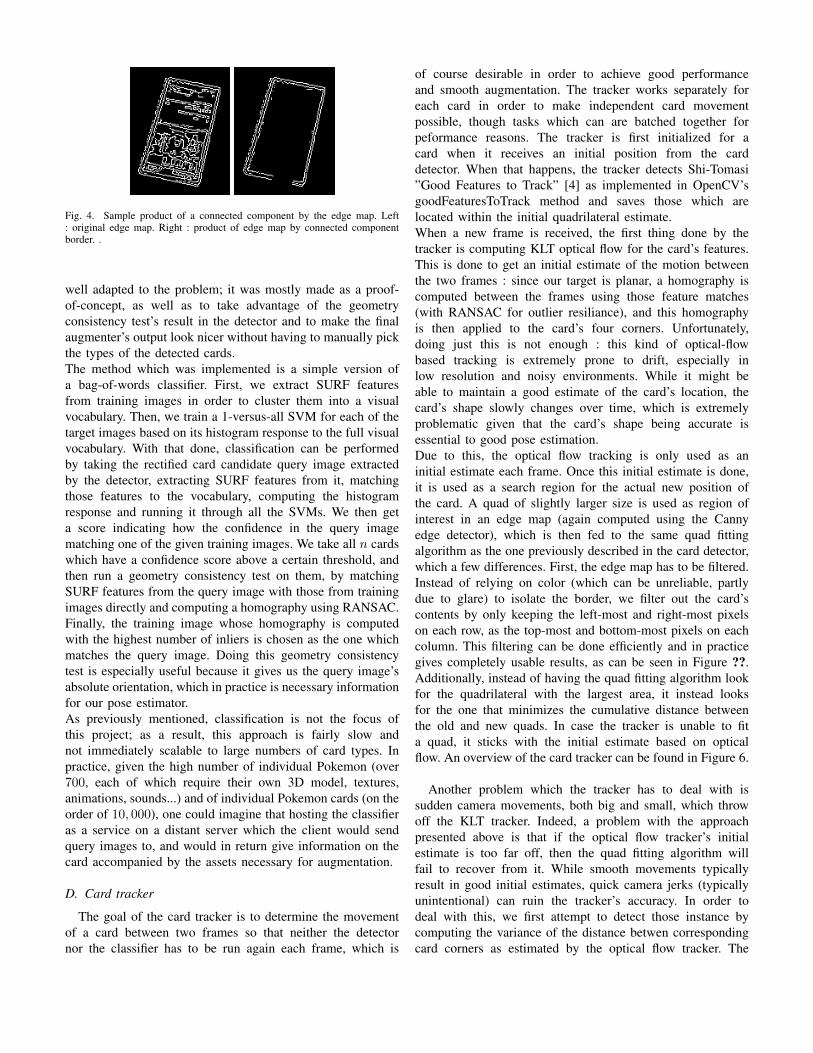
Fig. 4. Sample product of a connected component by the edge map. Left: original edge map. Right : product of edge map by connected componentborder. .
well adapted to the problem; it was mostly made as a proof-of-concept, as well as to take advantage of the geometryconsistency test’s result in the detector and to make the finalaugmenter’s output look nicer without having to manually pickthe types of the detected cards.The method which was implemented is a simple version ofa bag-of-words classifier. First, we extract SURF featuresfrom training images in order to cluster them into a visualvocabulary. Then, we train a 1-versus-all SVM for each of thetarget images based on its histogram response to the full visualvocabulary. With that done, classification can be performedby taking the rectified card candidate query image extractedby the detector, extracting SURF features from it, matchingthose features to the vocabulary, computing the histogramresponse and running it through all the SVMs. We then geta score indicating how the confidence in the query imagematching one of the given training images. We take all n cardswhich have a confidence score above a certain threshold, andthen run a geometry consistency test on them, by matchingSURF features from the query image with those from trainingimages directly and computing a homography using RANSAC.Finally, the training image whose homography is computedwith the highest number of inliers is chosen as the one whichmatches the query image. Doing this geometry consistencytest is especially useful because it gives us the query image’sabsolute orientation, which in practice is necessary informationfor our pose estimator.As previously mentioned, classification is not the focus ofthis project; as a result, this approach is fairly slow andnot immediately scalable to large numbers of card types. Inpractice, given the high number of individual Pokemon (over700, each of which require their own 3D model, textures,animations, sounds...) and of individual Pokemon cards (on theorder of 10, 000), one could imagine that hosting the classifieras a service on a distant server which the client would sendquery images to, and would in return give information on thecard accompanied by the assets necessary for augmentation.
D. Card tracker
The goal of the card tracker is to determine the movementof a card between two frames so that neither the detectornor the classifier has to be run again each frame, which is
of course desirable in order to achieve good performanceand smooth augmentation. The tracker works separately foreach card in order to make independent card movementpossible, though tasks which can are batched together forpeformance reasons. The tracker is first initialized for acard when it receives an initial position from the carddetector. When that happens, the tracker detects Shi-Tomasi”Good Features to Track” [4] as implemented in OpenCV’sgoodFeaturesToTrack method and saves those which arelocated within the initial quadrilateral estimate.When a new frame is received, the first thing done by thetracker is computing KLT optical flow for the card’s features.This is done to get an initial estimate of the motion betweenthe two frames : since our target is planar, a homography iscomputed between the frames using those feature matches(with RANSAC for outlier resiliance), and this homographyis then applied to the card’s four corners. Unfortunately,doing just this is not enough : this kind of optical-flowbased tracking is extremely prone to drift, especially inlow resolution and noisy environments. While it might beable to maintain a good estimate of the card’s location, thecard’s shape slowly changes over time, which is extremelyproblematic given that the card’s shape being accurate isessential to good pose estimation.Due to this, the optical flow tracking is only used as aninitial estimate each frame. Once this initial estimate is done,it is used as a search region for the actual new position ofthe card. A quad of slightly larger size is used as region ofinterest in an edge map (again computed using the Cannyedge detector), which is then fed to the same quad fittingalgorithm as the one previously described in the card detector,which a few differences. First, the edge map has to be filtered.Instead of relying on color (which can be unreliable, partlydue to glare) to isolate the border, we filter out the card’scontents by only keeping the left-most and right-most pixelson each row, as the top-most and bottom-most pixels on eachcolumn. This filtering can be done efficiently and in practicegives completely usable results, as can be seen in Figure ??.Additionally, instead of having the quad fitting algorithm lookfor the quadrilateral with the largest area, it instead looksfor the one that minimizes the cumulative distance betweenthe old and new quads. In case the tracker is unable to fita quad, it sticks with the initial estimate based on opticalflow. An overview of the card tracker can be found in Figure 6.
Another problem which the tracker has to deal with issudden camera movements, both big and small, which throwoff the KLT tracker. Indeed, a problem with the approachpresented above is that if the optical flow tracker’s initialestimate is too far off, then the quad fitting algorithm willfail to recover from it. While smooth movements typicallyresult in good initial estimates, quick camera jerks (typicallyunintentional) can ruin the tracker’s accuracy. In order todeal with this, we first attempt to detect those instance bycomputing the variance of the distance betwen correspondingcard corners as estimated by the optical flow tracker. The
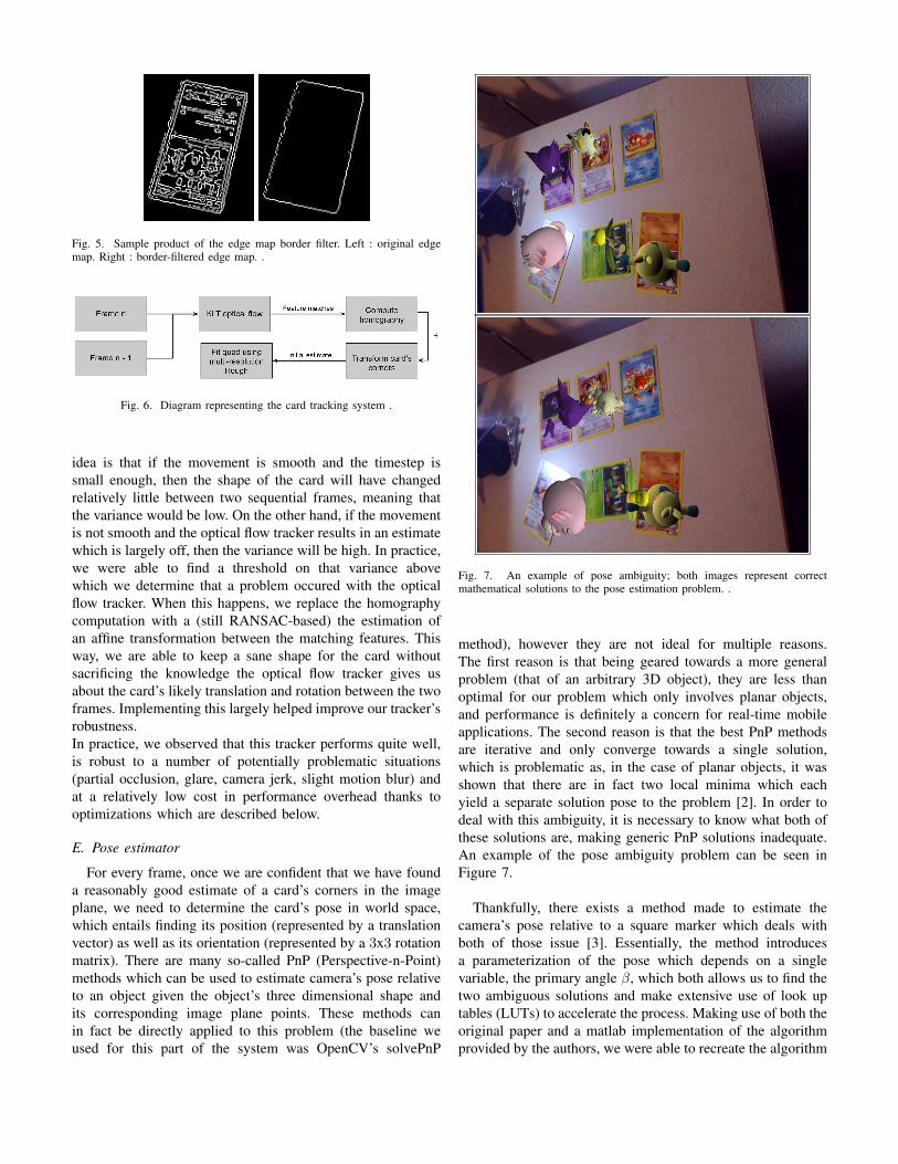
Fig. 5. Sample product of the edge map border filter. Left : original edgemap. Right : border-filtered edge map. .
Fig. 6. Diagram representing the card tracking system .
idea is that if the movement is smooth and the timestep issmall enough, then the shape of the card will have changedrelatively little between two sequential frames, meaning thatthe variance would be low. On the other hand, if the movementis not smooth and the optical flow tracker results in an estimatewhich is largely off, then the variance will be high. In practice,we were able to find a threshold on that variance abovewhich we determine that a problem occured with the opticalflow tracker. When this happens, we replace the homographycomputation with a (still RANSAC-based) the estimation ofan affine transformation between the matching features. Thisway, we are able to keep a sane shape for the card withoutsacrificing the knowledge the optical flow tracker gives usabout the card’s likely translation and rotation between the twoframes. Implementing this largely helped improve our tracker’srobustness.In practice, we observed that this tracker performs quite well,is robust to a number of potentially problematic situations(partial occlusion, glare, camera jerk, slight motion blur) andat a relatively low cost in performance overhead thanks tooptimizations which are described below.
E. Pose estimator
For every frame, once we are confident that we have founda reasonably good estimate of a card’s corners in the imageplane, we need to determine the card’s pose in world space,which entails finding its position (represented by a translationvector) as well as its orientation (represented by a 3x3 rotationmatrix). There are many so-called PnP (Perspective-n-Point)methods which can be used to estimate camera’s pose relativeto an object given the object’s three dimensional shape andits corresponding image plane points. These methods canin fact be directly applied to this problem (the baseline weused for this part of the system was OpenCV’s solvePnP
Fig. 7. An example of pose ambiguity; both images represent correctmathematical solutions to the pose estimation problem. .
method), however they are not ideal for multiple reasons.The first reason is that being geared towards a more generalproblem (that of an arbitrary 3D object), they are less thanoptimal for our problem which only involves planar objects,and performance is definitely a concern for real-time mobileapplications. The second reason is that the best PnP methodsare iterative and only converge towards a single solution,which is problematic as, in the case of planar objects, it wasshown that there are in fact two local minima which eachyield a separate solution pose to the problem [2]. In order todeal with this ambiguity, it is necessary to know what both ofthese solutions are, making generic PnP solutions inadequate.An example of the pose ambiguity problem can be seen inFigure 7.
Thankfully, there exists a method made to estimate thecamera’s pose relative to a square marker which deals withboth of those issue [3]. Essentially, the method introducesa parameterization of the pose which depends on a singlevariable, the primary angle β, which both allows us to find thetwo ambiguous solutions and make extensive use of look uptables (LUTs) to accelerate the process. Making use of both theoriginal paper and a matlab implementation of the algorithmprovided by the authors, we were able to recreate the algorithm

in C++ and integrate it into our system. Of course, becausethe algorithm is made to work with square targets while oursare rectangular, we apply the right scaling transform beforecalling the pose estimator. This makes it especially criticalythat the card’s orientation be known, as applying the scalingover the wrong direction would yield a wrong pose.In order to deal with pose ambiguities, we rely having morethan a single card being tracked by our system. Each card poseyields 4 points in 3D, on which we can use RANSAC to fit aplane. Given the nature of the ambiguities, this should allowus to find the plane the cards are actually located on, sincewe assume that all cards are coplanar. Then, using this plane’snormal vector, we can, for each card, find the pose which isclosest in orientation to that plane, which should be the posewe are after.In addition to this, we make use of the fact that all cards arelocated in the same plane to deal with potential outlier cards.For example, there are situations in which 3 cards will havebeen tracked properly, but the fourth’s corners are improperlyregistered for a few frames. By default, the fourth card’s posewould be computated as being completely different from theothers. In order to deal with this, we cluster plane normalsextracted from each card’s pose, determine which normalsmight be outliers, and then compute the plane normal as theaverage of inlier normals. We then reinject that average normalinto each card’s pose by setting it and then applying Gramm-Schmidt orthonormalization to the rotation matrix.
F. Scene augmenter
The scene augmenter module was made using OpenGL ES2.0 for rendering. It works by first transferring the currentfrom to the GPU as a texture, and rendering it as a flat image,clearing the depth buffer at the same time. Then, a projectionmatrix is computed for the actual augmentation. This cameramatrix is based on the camera matrix K, but is modifiedin order to preserve depth information, which is needed forOpenGL rendering. If we have :
K =
fx 0 cx0 fy cy0 0 1
Then the projection matrix is as follows :
2fxw 0 2cx
w − 1 0
02fyh 1− 2cy
h 0
0 0 n+fn−f
nfn−f
0 0 1 0
Where w and h are the frame’s width and height respectively,n is the near plane’s distance and f is the far plane’s distance.The models used for augmentation are rendered using anOpenGL ES 2.0 OBJ parser and renderer written for theoccasion.
G. Platform-specific optimizations
In order to get this complex system to run at acceptablespeeds on a mobile device, many optimization specific to theplatform had to be made. The first one is of course the useof look-up tables for pose estimation, which was mentionedabove. The second one has to do with the quad fittingalgorithm also described above. As it is used in the tracker, it isimportant that it be very efficient. Its initial implementation,based on the HoughLines function defined in OpenCV, wasfound to perform very poorly. After investigation, it turnedout that while the function was based on look-up tables,those were re-generated each time the function was called.Additionally, parts of the function made use of doubles whichare far slower than single precision floats on our target device.In order to improve this design, the hough line function wasreimplemented, based on the OpenCV code, but changing theway look-up tables are generated (only once per resolutionvalue), all the code which used double precision floats, andactually doing away with floats in some parts of the functionby switching the look-up tables to use fixed point math. Noloss in precision was measured, while the average call to thefunction was made 6 times faster.Another costly operation in the tracking pipeline was found tobe the sparse KLT optical flow calls. First of all, the individualcalls made for each card’s tracking were mutualized into asingle call using for all tracked features at once, which helpedmake the use of optical flow more tractable. Additionally, theoptical flow computation was completely moved from the CPUto the GPU using CUDA, which made the process twice asfast. Similarly, the computation of the Canny edge map (afterthe Gaussian kernel) was changed to be done using CUDA,multiplying the speed threefold. A related design choice hadall ”fundamental” image transformations such as the edge mapcomputation, color correction and conversions all be stored ina single ”frame sequence” object in order to make sure that thesame computation would never be done more than it neededto be each frame.Finally, in order to make use of the fact that our target devicehas not only powerful GPGPU capabilities but also a quad coreCPU, the card tracking process was changed to make good useof multithreading by spawning 4 worker threads each able ofprocessing an individal card’s tracking in parallel to others. Inmost cases, this multiplied the tracker’s overall speed by 4.A visualization of the final tracking pipeline can be seen inFigure 8.
III. RESULTS
A. Performance
As is indicated by the previous section, performance wasa major concern while making this application. In the end,we were able to achieve an overall average of 14 frames persecond in most situations with 5 or fewer cards, which is morethan enough to be considered real time application. In TableI, the average time taken for each task of main loop can befound. What we can see is that the optimizations made to the

Fig. 8. Diagram representing the current tracking pipeline’s distribution acrosscomputing devices .
TABLE IPERFORMANCE OF THE MAIN LOOP. PERFORMANCE RECORDED WHEN
TRACKING 4 CARDS.
Task Device Average time takenSparse optical flow GPU 19.6msCanny edge map GPU 19.3ms
Single Hough transform CPU 10.2msQuad fitting CPU 23.6ms
All cards tracking update GPU and CPU 45.5msSingle card pose estimate CPU 0.58msAll cards pose estimate CPU 3.2msProcessing entire frame GPU and CPU 73.5ms
system’s various modules were very effective. For instance,each pose estimate is done in only half a millisecond; similarly,the multithreading used to parallelize card tracking results invery little overhead, allowing the application to process 4 cardsalmost as fast as a single core is able to process a single one.
B. Quality of augmentation
It is difficult to accurately gauge the accuracy of theaugmentation as we do not have any kind of ground truth,especially in the case of orientation. A (flawed) metric whichcan be used to somewhat assess the quality of the tracker isthe number of cards for which the tracked is able to fit anew quad each frame. A graph representing this metric canbe found in Figure 9; interpreting it, we can see that mostcards don’t seem to go long without getting a new quad fit toprevent drift, except for one which apparently doesn’t get anew fit for the entire middle section of the sequence.Qualitatively, we can say that the tracker manages to be robustto a number of problematic situations. For example, it is able tobe robust to glare in certain situations, as can be seen in Figure10. Additionally, it is able to withstand partial occlusions forshort periods of time, as can be seen in Figure 11. It is alsorobust enough that a variety of angles work well, even verylow angles which let the user look at augmented models fromthe side, as can be seen in Figure 12. More impressively, it isrobust enough that having a user move cards while the cameraitself is being moved around with their finger is not a problem,be it rotations or translations, as can be seen in Figure 13.That being said, while the tracking is overall robust andaccurate, the final result is not perfect. Unfortunately, the
Fig. 9. Graph representing the number of frames which the tracker success-fully fit a quad to over time, in a scene with a total of 6 cards being tracked.
Fig. 10. An example of the tracker showing robustness to glare. (bottom leftcard) .
output still suffers from intermittent jitters, typically due topoor quad fits happening in certain frames. This indicates thattracking could still be improved, as well as the normal vectoroutlier rejection mentioned previously.A video showing the augmenter running under a variety ofconditions (including the ones described above) can be foundattached to this paper.
IV. FUTURE WORK
While this project’s results are very encouraging, they donot make a full product. Due to lack of time, all potentialoptimizations and features could not be included in thisproject. For example, the tracking pipeline presented in Figure8, while already producing good enough performance, leavesto be desired in that it does not make optimal use of allcomputing devices at all times. Instead, one could imaging atracking pipeline closer to that described in Figure 14, whichhas the GPU processing data for frame n while the CPU is

Fig. 11. An example of the tracker showing robustness to partial occlusion.(bottom right card) .
Fig. 12. An example of the tracker showing robustness to a low viewingangle. .
Fig. 13. An example of the tracker keeping up with a variety of user cardmovements.
Fig. 14. Diagram representing the a possibly better tracking pipeline’sdistribution across computing devices .
still processing data from frame n−1, as such a pipeline couldas much as double the currently observed framerate.Optimization is not the only part of the project which couldbe expanded upon. Indeed, although the project runs on amobile device and requires an accurate estimate of the device’slocation relative to its environment for proper augmentation, itcurrently makes no use of any of the on-board inertial sensors.One could imagine that integrating signals from those sensorscould help make tracking even more robust, as well as give agood heuristic to help decide between ambiguous poses in thepose estimator.Finally, a big part of trading card games is actually playingwith them. While augmenting cards with 3D models alreadyhelps make the game more engaging, it is not enough foran application which aims to fully augment card game duels,by for example animating Pokemon attacking other Pokemon.While the underlying rendering part is trivial, detecting thata player is commanding one of its creatures to attack isnot. Doing so would require maintaining a coherent map ofthe battle field, including attached semantics such as cardownership and card status (for example, detecting that a cardis sideways which in a lot of card games is indicative of anaction). One could imagine implementing some kind of card-based gesture recognition system to allow the application tofully follow the duel.
V. CONCLUSION
With this paper, we demonstrated that it is entirely possibleto augment a trading card game in real time even in spiteof the absence of specially designed markers on cards, of afixed camera or of heavy computation capabilities. We paidclose attention to code and algorithm optimization in orderto get the system running smoothly on a mobile device, theNvidia SHIELD tablet. We leveraged of both the CPU andthe GPU for computation, and found that our card tracker isrobust enough to handle users moving cards while the camerais also moving independently. We made suggestions for waysto expand on the project in both purely technical ways andmore feature-oriented ones.
REFERENCES
[1] Jun Rekimoto and Yuji Ayatsuka, CyberCode: Designing AugmentedReality Environments with Visual Tags 2001.

[2] G. Schweighofer and A. Pinz, Robust pose estimation from a planar target2006.
[3] Shiqi Li and Chi Xu, Efficient Lookup Table Based Camera PoseEstimation for Augmented Reality 2011.
[4] Jianbo Shi and Carlo Tomasi, Good Features to Track 1994.[5] Pokepedia, Pokepedia list of Pokemon cards. http://www.pokepedia.net/