real-time coding for kinesthetic and tactile signals1047083/fulltext01.pdf · real-time coding for...
TRANSCRIPT
IN DEGREE PROJECT INFORMATION AND COMMUNICATION TECHNOLOGY,SECOND CYCLE, 30 CREDITS
, STOCKHOLM SWEDEN 2016
Real-time Coding for Kinesthetic and Tactile Signals
LIYANG ZHANG
KTH ROYAL INSTITUTE OF TECHNOLOGYSCHOOL OF ELECTRICAL ENGINEERING
Real-time Coding for Kinesthetic andTactile Signals
LIYANG ZHANG
Master in Wireless SystemsDate: October 2016Supervisor: Volodya Grancharov (Ericsson),Saikat Chatterjee (KTH)Examiner: Mikael SkoglundSchool of Electrical Engineering
i
Abstract
The Tactile Internet is at the core of the 5G era, when the world will experience paradigmshift from content-delivery networks to service/labour-delivery ones. Systems that enablewireless communications of haptic data feature bi-directionality, high packet rate andresolution, large degrees of freedom, and above all, strict latency requirements in manyapplications, aggravating the shortage of wireless resources. Thus, more efficient hapticdata reduction techniques are continuously summoned for. Previous studies on hapticcompression mostly resort to DPCM/ADPCM plus entropy coding and perception-baseddown-sampling for real-time scenarios, and model-based techniques such as DCT andLP for the rest. However, with few exceptions they always segregate tactile signals fromkinaesthetic signals, employing only kinaesthetic feedbacks in real-time compression ex-periments. In addition, these techniques are not optimized for efficient performance atscale.
This thesis project proposes a novel multi-channel real-time haptic compression sys-tem aimed at teleoperation applications with both kinaesthetic and tactile feedbacks. Itconsists of a lossy compression layer featuring predictive coding and a lossless layerfeaturing channel reshuffle and group transmission. By using different quantizer de-signs in the lossy layer, it abates the need for entropy coding, and leave room for futureperception-based data compression modules. The lossless layer exploits inter-channelsparsity for further data reduction. The system is evaluated on a tactile texture databasepublished by University of Pennsylvania in MATLAB. The performance measurementsare in both time and frequency domain, mostly objective, but include subjective consider-ations as well.
Keywords: Tactile Internet, real-time data reduction, predictive coding, sparse coding,kinesthetic and tactile signal processing, multi-channel.
ii
Sammanfattning
Haptisk kommunikation är central för de nya tjänster och användningsområden, t.ex.fjärrstyrning, som de kommande 5G-nätverken möjliggör. Haptiska system kräver av sinnatur tvåvägskommunikation, ofta med hög bandbredd och upplösning, många frihets-grader, och framför allt är latenskraven kritiska i många tillämpningar. Därför är intres-set för kompressionsmetoder av haptisk data av stort intresse. Tidigare studier av hap-tisk kompression är mestadels baserade på DPCM/ADPCM med entropikodning samtperceptionsbaserad nedsampling för realtidsscenarier, medan modellbaserade teknikersåsom DCT och LP förekommer i övriga fall. Med några få undantag särskiljer dessa stu-dier dock alltid taktila och kinestetiska signaler, och avhandlar endast kinestetisk åter-koppling för kodning i realtid. Dessutom är dessa tekniker inte optimerade för effektivprestanda i stor skala.
Detta examensarbete föreslår ett nytt haptiskt flerkanals-komprimeringssystem förrealtid ämnat för applikationer med både kinestetiska och taktila återkopplingar. Det be-står av ett lager med destruktiv prediktiv kodning samt ett lager förlustfri kompressiongenom omstrukturering och gruppering av data från flera kanaler. Genom att användaolika kvantiseringsmetoder i det förstörande kodningslagret minskar behovet av entropi-kodning och lämnar utrymme för framtida perceptionsbaserade komprimeringsmoduler.Det icke-förstörande lagret utnyttjar också glesheten i datasekvenserna för de gemensamtkodade kanalerna för ytterligare datareduktion. Systemet utvärderas i MATLAB med tak-til data som publicerats av University of Pennsylvania. Prestandan bedöms främst i ob-jektiva mått i såväl tids- som frekvensdomän men även utifrån subjektiva aspekter.
Nyckelord: haptisk kommunikation, realtid, flerkanalig, kompression, prediktiv kod-ning, gles kodning, kinestetisk och taktil signalbehandling.

iii
Acknowledgements
The bulk of this thesis project is accomplished at Ericsson Research, Stockholm in year2016, between January and June. I would like to express my heartfelt gratitude to VolodyaGrancharov, my supervisor at Ericsson, for his great effort and patience in guiding methrough all the difficulties and confusions. Without his wise insights and criticism, thegoal of the project would not have been achieved. I would also like to thank José Araújo,for his constant advice and detailed comments during the writing of the thesis report.His passion towards new technologies and solving problems has encouraged me a greatdeal.
The two years at KTH has witnessed the growth of me in both expertise and expe-rience. I am truly thankful for Saikat Chatterjee, my thesis supervisor at the university,and the amiable and strict teacher for two of my courses. Last but not least, my sinceregratefulness to my parents and friends, for their selfless love and support.
Contents
Contents iv
1 Introduction 11.1 Tactile Internet and the 5G Era . . . . . . . . . . . . . . . . . . . . . . . . . . . 11.2 Haptic Coding: A Review . . . . . . . . . . . . . . . . . . . . . . . . . . . . . . 2
1.2.1 Development and Classification . . . . . . . . . . . . . . . . . . . . . . 21.2.2 Reflection on Previous Work . . . . . . . . . . . . . . . . . . . . . . . . 4
1.3 Objectives . . . . . . . . . . . . . . . . . . . . . . . . . . . . . . . . . . . . . . . 61.4 Outline . . . . . . . . . . . . . . . . . . . . . . . . . . . . . . . . . . . . . . . . . 6
2 Background 82.1 Haptic Perception and Haptic Technology . . . . . . . . . . . . . . . . . . . . 8
2.1.1 Characteristics of Human Haptic Perception . . . . . . . . . . . . . . . 82.1.2 Haptic Devices . . . . . . . . . . . . . . . . . . . . . . . . . . . . . . . . 10
2.2 Real-time Compression for Haptic Signals . . . . . . . . . . . . . . . . . . . . 132.2.1 Quantization . . . . . . . . . . . . . . . . . . . . . . . . . . . . . . . . . 132.2.2 Differential Pulse Code Modulation (DPCM) . . . . . . . . . . . . . . 152.2.3 Entropy Coding . . . . . . . . . . . . . . . . . . . . . . . . . . . . . . . . 162.2.4 Perceptual Deadband (PD) . . . . . . . . . . . . . . . . . . . . . . . . . 17
2.3 Performance Evaluation Methods . . . . . . . . . . . . . . . . . . . . . . . . . 182.3.1 Objective Measurements . . . . . . . . . . . . . . . . . . . . . . . . . . . 182.3.2 Subjective Measurements . . . . . . . . . . . . . . . . . . . . . . . . . . 19
3 The Compression System 213.1 System Overview . . . . . . . . . . . . . . . . . . . . . . . . . . . . . . . . . . . 213.2 DPCM/PCM Coding Layer . . . . . . . . . . . . . . . . . . . . . . . . . . . . . 22
3.2.1 Quantizer Design . . . . . . . . . . . . . . . . . . . . . . . . . . . . . . . 223.2.2 Predictor Design . . . . . . . . . . . . . . . . . . . . . . . . . . . . . . . 26
3.3 Sparse Coding Part . . . . . . . . . . . . . . . . . . . . . . . . . . . . . . . . . . 273.3.1 Shuffle Encoder and Decoder . . . . . . . . . . . . . . . . . . . . . . . . 273.3.2 Grouping Encoder and Decoder . . . . . . . . . . . . . . . . . . . . . . 28
4 The Testing Database 29
5 Experiments and Results 315.1 Data Pre-processing and Analysis . . . . . . . . . . . . . . . . . . . . . . . . . 315.2 Performance of DPCM/PCM Coding Part . . . . . . . . . . . . . . . . . . . . 32
5.2.1 Time-domain SNR . . . . . . . . . . . . . . . . . . . . . . . . . . . . . . 32
iv
CONTENTS v
5.2.2 Spectral Distortion . . . . . . . . . . . . . . . . . . . . . . . . . . . . . . 385.2.3 Summary . . . . . . . . . . . . . . . . . . . . . . . . . . . . . . . . . . . 39
5.3 Performance of Sparse Coding Part . . . . . . . . . . . . . . . . . . . . . . . . 415.4 Overall Performance . . . . . . . . . . . . . . . . . . . . . . . . . . . . . . . . . 42
6 Conclusions and Future Work 456.1 Conclusions . . . . . . . . . . . . . . . . . . . . . . . . . . . . . . . . . . . . . . 456.2 Future Work . . . . . . . . . . . . . . . . . . . . . . . . . . . . . . . . . . . . . . 46
Bibliography 47
A DRS Record Sheet 51A.1 DRS of sparse coding layer . . . . . . . . . . . . . . . . . . . . . . . . . . . . . 51A.2 DRS records of the proposed compression system . . . . . . . . . . . . . . . . 52

Chapter 1
Introduction
1.1 Tactile Internet and the 5G Era
Like with the past four generations, the emerging 5G technology is again aimed at rev-olutionizing the world, by providing reliable transmission of an exponentially rocketingvolume of data across the wireless network. A general vision of the 5G Era is to augmentthe data capacity of 4G by 1000 times and lower the end-to-end round-trip latency to theorder of 1ms, about one twentieth of that of 4G [1].
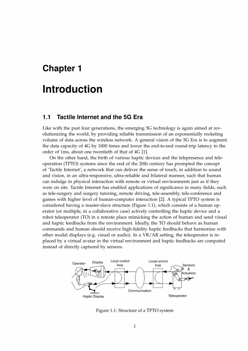
On the other hand, the birth of various haptic devices and the telepresence and tele-operation (TPTO) systems since the end of the 20th century has prompted the conceptof ‘Tactile Internet’, a network that can deliver the sense of touch, in addition to soundand vision, in an ultra-responsive, ultra-reliable and bilateral manner, such that humancan indulge in physical interaction with remote or virtual environments just as if theywere on site. Tactile Internet has enabled applications of significance in many fields, suchas tele-surgery and surgery tutoring, remote driving, tele-assembly, tele-conference andgames with higher level of human-computer interaction [2]. A typical TPTO system isconsidered having a master-slave structure (Figure 1.1), which consists of a human op-erator (or multiple, in a collaborative case) actively controlling the haptic device and arobot teleoperator (TO) in a remote place mimicking the action of human and send visualand haptic feedbacks from the environment. Ideally, the TO should behave as humancommands and human should receive high-fidelity haptic feedbacks that harmonize withother modal displays (e.g. visual or audio). In a VR/AR setting, the teleoperator is re-placed by a virtual avatar in the virtual environment and haptic feedbacks are computedinstead of directly captured by sensors.
Figure 1.1: Structure of a TPTO system
1
2 CHAPTER 1. INTRODUCTION
However, Tactile Internet also imposes ever stringent requirements on data rates andlatency in order to minimize immersion dropout. The requirements somewhat differ be-tween the transmission of kinaesthetic and tactile feedbacks (for the definitions of thetwo terms, see Section 2.1.1). For instance, the former is usually used in closed-loop scenesand thus has stricter delay constraints, while the latter has been used mostly in probing,rendering and recognition tasks that have loose delay constraints, but overall, such sys-tems feature round-trip latency of 1ms, as well as large Degrees of Freedom (DoF) andhigh sample resolutions [3], and we should be prepared to accommodate hundreds ofthousands of such systems in the future.
As probably the most promising new application scenario in the dawning 5G era,Tactile Internet stands in the spotlight of many technology and innovation companiesworldwide. For instance, Ericsson has announced 5G research in collaboration with King’sCollege London, and the setup of a 5G Tactile Internet Laboratory. The infrastructure andprotocol design of 5G should strive to be more suitable for haptic communications, i.e.,use smarter bandwidth allocation and reuse, lighter packet header, low-latency modu-lation, etc. Meanwhile, viewing from the haptic systems’ perspective, coding the dataefficiently can surely alleviate the network load and in turn allow the network to servemore devices. And after all, it has been proved that for wireless telepresence applica-tions, higher traffic means shorter lifetime of the mobile agents and higher energy con-sumption [4]. On these grounds, I feel both interested and incumbent to work on a novelcompression algorithm design for haptic systems.
1.2 Haptic Coding: A Review
1.2.1 Development and Classification
Haptic devices and systems utilize haptic signals such as force, position, rotation andacceleration to enable physical interaction between some parts of human body (usuallyhand or arm) and a virtual or remote inaccessible environment. Hence, haptic interfacesare usually responsible for both measuring the haptic signals produced by human thatare intended to exert on the environment and displaying the haptic feedback signals. Forexample, the PHANToM haptic interface first developed in 1994 at MIT that tracks themovement of a user’s fingertip in terms of position and gives force feedback is one of themost renowned early commercialized product [5].
During past few decades, great effort in multimedia technology design has been de-voted to creating immersive experience, i.e. computers displaying an inclusive, exten-sive, surrounding and vivid illusion of reality to the senses of a human participant [6].Traditional work exploits mostly the possibilities lie in hearing and vision, and accom-plishments including the Dolby stereo, 3D film technology, as well as devices like head-mounted-display (HMD) and Microsoft Kinect have been acknowledged globally. As aresult, efficient coding and compression schemes for audio and visual signals have beenextensively explored.
However, then people began to be no longer satiable with two sensory modalities.Cases are abundant in which mere audio and visual displays could trigger incoherencebetween real environments and synthesized ones in human perception that will causeimmersion drop out or task performance deterioration. In fact, haptic interfaces that pro-
CHAPTER 1. INTRODUCTION 3
vide haptic drive and feedback adapted for different parts of the body and different usesare constantly being created since the 1970s, but it was in more recent time that peoplerealize the significant role of haptic signals in addition to audio and visual signals inboosting the subjective feeling of immersion and ability to perform complex tasks [7].
Although the processing of haptic signals and that of audio and visual signals shouldhave much in common, the former is bounded with higher restrictions and complexitybecause of the following factors:
1. Haptic activities are bi-directional – While data transmission in audio and visual ap-plications are unidirectional, which means users interact with these systems on apassive or half-duplex basis, information flows in haptic systems are almost alwaysbidirectional, since the touch feedbacks very much depend on how we reach out tothe environment. Consequently, the amount of data to be transmitted over the net-work is doubled, and latency is more critical than in audio and visual systems, forthe immersiveness and stability of a closed-loop system to be achieved.
2. Human haptic perception is complicated and hard to be incorporated in haptic coding – Thetrick for creating immersive experience while also transferring information econom-ically is by studying the spatial and temporal limitation of human haptic percep-tion and employing sensors and algorithm parameters compatible to those limits.While the temporal and spatial perception capability of human hearing and visionare much understood, e.g. 30 frames/sec is sufficient for human to see continuousmovement and 4kHz sampling rate is basic for speech telephony [8], human hapticperception is rather poorly studied. While we can study audio or visual percep-tion by solely looking at human auditory or visual systems, we cannot do the samething for haptic perception, since it overwhelms every inch of our body. Large DoFis needed for haptic devices to mimick this dexterity and perceptual limit and res-olution vary with different devices that involve participation of different parts ofthe body. Haptic perception comprises a variety of signals (e.g. pressure, friction,vibration, tapping, damping and so on for force signal alone). It is already much tostudy human perception of these genres individually, let alone the fact that they areoften interweaved when forming complete touch stimuli.
The design of haptic codecs has been following two trains of thought, for online TPTOapplications and non-real-time applications each: TPTO applications require ‘transparency’,that human operator does not perceive the presence mediating technology when experi-encing the target environment [3], and thus only real-time schemes based on sample-wiseprocessing are considered. These schemes can be subcategorized into lossy and losslessones, based on whether the signal can be reconstructed perfectly. Lossy compression donot guarantee perfect reconstruction but can achieve satisfying performance in termsof signal-to-noise-ratio (SNR) and human perception using various downsampling andquantization methods. Lossless compression algorithms like Huffman Coding and Arith-metic Coding exploit the temporal redundancy in signals and allow for exact reconstruc-tion. Interestingly, nearly all previous studies on haptic coding in TPTO systems assumekinesthetic feedback only. In [3] a passive extrapolative downsampling strategy is raisedand evaluated on a TPTO system with velocity(feedforward)-force(feedback) architecture.In [9] Shahabi et.al analyzed distortion of several sampling methods and Adaptive Dif-ferential Pulse Code Modulation (ADPCM) individually on kinesthetic data and testedthe effectiveness and efficiency when combining ADPCM and Adaptive sampling. In [10]
4 CHAPTER 1. INTRODUCTION
and [11] DPCM/ADPCM combined with quantization or lossless compression on forcefeedback data are studied.
On the other hand, block-based compression methods that have noticeable bufferdelay like Linear Prediction (LP) and Discrete Cosine Transform (DCT) frequently em-ployed in audio and visual compression are applicable to non-real-time tasks as in [12]and [13], or tasks with less strict delay requirements [14] [15] [16]. Here is where the tac-tile feedback use cases, or vibrotactile feedbacks, are employed more often, for tactile sig-nals are believed to be similar to speech signals, and are less seen in teleoperation sce-narios.
However, in this thesis study, we try to make our proposed compression algorithmsas general-purpose and scalable as possible. This means we strive to address the TPTOscenario for both kinesthetic and tactile signals, and optimize the algorithm on largenumber of inputs. With 1ms latency constraint in mind, we only consider sample-basedcoding schemes.
While most of the abovementioned literature designed the compression algorithmswith no constraint in the subjective human perception dimension at all or only use it asa performance measurement in the analysis phase, many other studies exhibited enor-mous interest in the huge data reduction potential lying in human perception limit. Hin-terseer et.al were the first to apply a perceptual deadband (PD) sampling approach tocompression of velocity and force signals, in which an incoming sample is only transmit-ted when it is considered perceptually different from the previously transmitted one [17].They later motivated a first-order linear-prediction-based PD method and a multi-DoFPD method as extensions [18]. In successive studies the simplest form of PD is mod-ified to boost performance for different signal types and take care of the passivity re-quirement in the closed-loop teleoperation systems [19] [20] [21] [22] [23]. In [24] Kam-merl et.al got inspiration from psychophysical study on dynamic haptic perception limitand came up with a hand-velocity-dependent PD algorithm for task-oriented contextswith success. Sakr et.al use a least-squares prediction-based PD scheme in combinationwith uniform quantization and adaptive Golomb-Rice codes for haptic data reduction intele-monitoring systems [25]. Studies [12] [26] conducted studies using vibrotactile tex-ture signals instead of kinesthetic signals, and both of them proposed a perception-basedcompression scheme that doesn’t go in the direction of time domain PD. In a recent arti-cle [27], cutaneous feedback is experimented on using PD with demonstrated feasibility.
1.2.2 Reflection on Previous Work
Admittedly, haptic coding is still a rather under-exploited area in many dimensions, de-spite the fruitful research over the years. In the course of literature reading for this thesisstudy, several of the dimensions have been clearly noticed:
1. Tactile feedbacks are rarely considered in teleoperation scenario, while the forward path is com-pletely forgotten.
Like mentioned in previous section, kinesthetic signals are much more frequentlystudied than tactile ones for real-time applications. [27] is the only work we findthat evaluate PD compression on cutaneous signal. Another thing is that most re-search focus on experiments with feedback signals, not signals in the feed-forwardpaths, regardless of the fact that their compression will certainly affect the feedbacksignal quality. Moreover, some signal types like force is more frequently used for
CHAPTER 1. INTRODUCTION 5
perceptual compression study than others like acceleration and position signals.While the Just Noticeable Difference (JND) for force signal has been extensively re-searched and reached an consensus independent of body site and test condition[18] [28], we have faint ideas of what should be the JND for acceleration, positionor velocity.
The haptic limit of human can be very complicated in the sense that it is dependentof body sites, passive/active exploration, visual/audio complementary information,mediating tools, subjects’ concentration level [29], etc. However, past studies con-trolled these above, especially when it comes to the visual/audio information. Moststudies cannot exempt visual/audio modalities completely from the haptic percep-tual experiments, since the virtual environment must be displayed to the partici-pants through the PC in many tasks. Since human beings are expert at integratingmultiple modalities in an optimal way, it is a very demanding to guarantee that thecompression solution we designed for one type of tasks will be suitable for othersas well.
2. Research on real-time non-perceptual compression has little diversity.
To the best of our knowledge, for lossy compression only ADPCM/DPCM withfixed scalar codebooks have been proposed and only Huffman Coding and Golomb-Rice Coding have been attempted for the lossless compression part so far. Hinter-seer et.al have pointed out that methods that use differential coding followed byentropy coding in previous work can suffer from a bad packet header to payloadratio [18] and are not entirely suitable for TPTO systems. Therefore it is reasonableto encourage more diversity to see if any improvement can be made.
3. Studies that take non-perceptual and perceptual paths are mostly isolated.
Studies that use agile quantization and sampling methods do not employ muchstudy on perception when designing algorithms and those that design from a PDpoint of view seldom consider smarter quantization methods or lossless compres-sion. Although this may be attributed to the fact that outcomes from these twopaths are judged and criticized by different criteria (distortion rate and percep-tual discriminability respectively), we believe there is room for merging the twobranches for even better efficiency, since they have their own advantages and arenot in alternative positions.
4. Existing studies seldom explore relevance among input channels.
Just think of a haptic glove with distributed sensors on the palm and figures, notonly the force signals in three dimensions at each sensing point can be coded andcompressed more efficiently, but also the sensing locations are likely to be corre-lated to each other in signal variation. There might be another leap in haptic com-pression algorithm design if we start to take channel-wise relevance into considera-tion.
5. The subjective measurement of perception-based compression is not standardized.
Researchers usually design their own psychophysical experiments to evaluate thetransparency performance of their compression algorithms based on different sub-jective grading standards. For instance, in [24] and [27] participants are required to
6 CHAPTER 1. INTRODUCTION
tune the deadband parameters freely and report the point when a disturbance ordifference in feeling is detected; in [13] researchers adopt the grading scale recom-mended by International Telecommunication Union (ITU) for subjectively assess-ing the impairment of audio/visual content, which allows subjects to choose fromfour subjective statements, i.e. ‘same’ ‘possibly same’ ‘possibly different’ and ‘dif-ferent’ when comparing the uncompressed and compressed signals; [21] and [23]use a measure similar to the ITU style, but replace the four statements with a grad-ing scale ranging from 0-100, with 0 representing ‘strongly disturbing/different’,and 100 representing ‘no difference’; a three-interval forced choice (3IFC) paradigmis used in [17] [18] and [26], where participants go through several repetitions ofexperiments asking them to pick out a different signal among a group, correct an-swers lead to a decrease in the deadband coefficient/ masking threshold and viceversa; whereas in [20] and [22] objective criteria like SNR and reduction rate areused and no subjective experiments are conducted. Although the experiments inall of the studies above try their best to make the process more impartial throughcareful choice of participants, elimination of excessive audio/visual information,training phase, repetition of experiments and other scientific research methodology,I found discussion of neither the convincing power of each method nor the superi-ority of one method over another in haptic perception context.
1.3 Objectives
Ideally we wish to make an improvement on all five aspects mentioned above throughour efforts. However, due to the time limit of this thesis project and immature infrastruc-ture, we will leave the fifth aspect, i.e., the choice and standardization of subjective mea-surement methods for haptic codecs, for future research. Our main objectives are listedas follows:
• Design a compression system suitable for TPTO systems with both kinesthetic andtactile feedbacks, and assess its performance on both types of signal.
• Explore multiple real-time lossy compression techniques similar to those employedfor audio and image processing, and make conclusions about their performance onhaptic signals.
• Make the system scalable to and efficient for systems with large number of inputchannels.
• Design the system mainly using non-perceptual techniques, but in a way that iscompatible with perceptual compression plug-ins. The performance evaluation aremainly based on objective indexes, but include subjective considerations as well.
The round-trip latency constraint throughout this study is 1ms, and signal samplingrate is kept at 1kHz.
1.4 Outline
The remainder of this thesis report is structured as follows. Chapter 2 is a comprehensivebackground study of haptic technology and the mathematics inside existing haptic data

CHAPTER 1. INTRODUCTION 7
real-time coding schemes. Especially, we incline our vision towards human perceptualcapacity perspective, which we believe is the foremost and ultimate principle underlyinga successful compression system.
Chapter 3 is the description of the proposed compression system. First the overviewof the whole system is given, followed by details of subsections of the system.
Chapter 4 introduces the database we use for evaluate the compression system.Chapter 5 presents all experiments and their corresponding results for testing the sys-
tem.And finally, chapter 6 summarizes over the entire design and analysis process, and
gives retrospective and future thinking on haptic coding.
Chapter 2
Background
2.1 Haptic Perception and Haptic Technology
2.1.1 Characteristics of Human Haptic Perception
The touch modality of human is managed by somatosensory system and can be subcat-egorized into kinesthesis, tactile/cutaneous sense and proprioception depending on thelocation of the sensory receptors involved. When it comes to engineering we are con-tent with the first two types of senses, where the stimuli come from outside of the body.Quoting Loomis and Lederman’s clear-cut boundary line of the two types of senses in[29], tactile/cutaneous sense should solely rely on cutaneous stimuli processed by mechanore-ceptors and thermoreceptors in the skin, such as recognition of a Braille character, or feel-ing the temperature or pinching of a needle; whereas kinesthetic sense refers to percep-tion through mechanoreceptors in muscles, bones and joints, in which if not completelyso the cutaneous stimuli should only serve as an indication of contact between humanand the object, such as judging the size of a ball by grabbing it or detecting a wall byreaching out an arm when blind-folded and with gloves on. Haptic perception is thendefined as ‘perception in which both cutaneous sense and kinesthesis convey significantinformation about distal objects and events’.
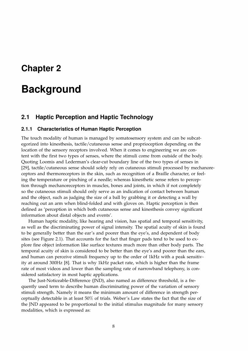
Human haptic modality, like hearing and vision, has spatial and temporal sensitivity,as well as the discriminating power of signal intensity. The spatial acuity of skin is foundto be generally better than the ear’s and poorer than the eye’s, and dependent of bodysites (see Figure 2.1). That accounts for the fact that finger pads tend to be used to ex-plore fine object information like surface textures much more than other body parts. Thetemporal acuity of skin is considered to be better than the eye’s and poorer than the ears,and human can perceive stimuli frequency up to the order of 1kHz with a peak sensitiv-ity at around 300Hz [8]. That is why 1kHz packet rate, which is higher than the framerate of most videos and lower than the sampling rate of narrowband telephony, is con-sidered satisfactory in most haptic applications.
The Just-Noticeable-Difference (JND), also named as difference threshold, is a fre-quently used term to describe human discriminating power of the variation of sensorystimuli strength. Namely it means the minimum amount of difference in strength per-ceptually detectable in at least 50% of trials. Weber’s Law states the fact that the size ofthe JND appeared to be proportional to the initial stimulus magnitude for many sensorymodalities, which is expressed as:
8
CHAPTER 2. BACKGROUND 9
∆I/I = k (2.1)
where ∆I is the magnitude of JND and I is the magnitude of stimulus. JND is some-times represented by ratio since in most cases it is approximately a constant within aspecific task modality, although it can fluctuate among individuals.
Figure 2.1: Spatial haptic acuity across human body [30]
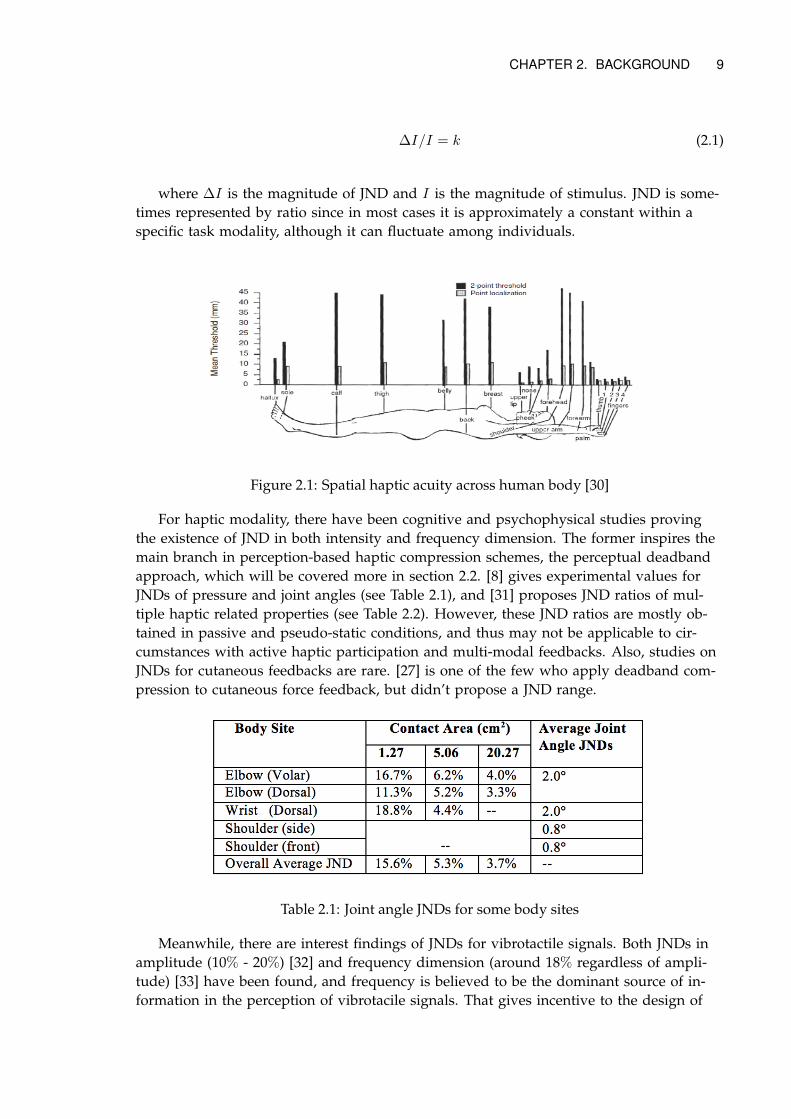
For haptic modality, there have been cognitive and psychophysical studies provingthe existence of JND in both intensity and frequency dimension. The former inspires themain branch in perception-based haptic compression schemes, the perceptual deadbandapproach, which will be covered more in section 2.2. [8] gives experimental values forJNDs of pressure and joint angles (see Table 2.1), and [31] proposes JND ratios of mul-tiple haptic related properties (see Table 2.2). However, these JND ratios are mostly ob-tained in passive and pseudo-static conditions, and thus may not be applicable to cir-cumstances with active haptic participation and multi-modal feedbacks. Also, studies onJNDs for cutaneous feedbacks are rare. [27] is one of the few who apply deadband com-pression to cutaneous force feedback, but didn’t propose a JND range.
Table 2.1: Joint angle JNDs for some body sites
Meanwhile, there are interest findings of JNDs for vibrotactile signals. Both JNDs inamplitude (10% - 20%) [32] and frequency dimension (around 18% regardless of ampli-tude) [33] have been found, and frequency is believed to be the dominant source of in-formation in the perception of vibrotacile signals. That gives incentive to the design of
10 CHAPTER 2. BACKGROUND
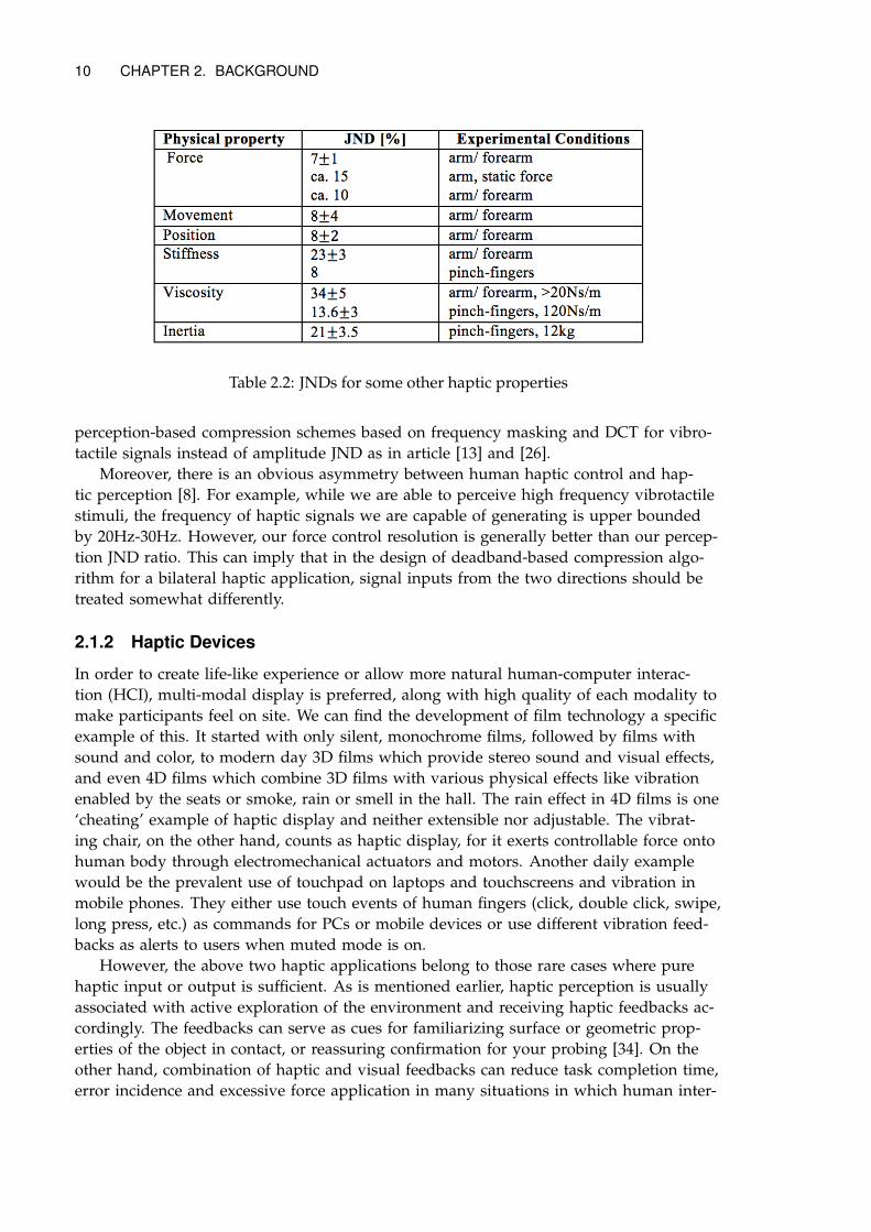
Table 2.2: JNDs for some other haptic properties
perception-based compression schemes based on frequency masking and DCT for vibro-tactile signals instead of amplitude JND as in article [13] and [26].
Moreover, there is an obvious asymmetry between human haptic control and hap-tic perception [8]. For example, while we are able to perceive high frequency vibrotactilestimuli, the frequency of haptic signals we are capable of generating is upper boundedby 20Hz-30Hz. However, our force control resolution is generally better than our percep-tion JND ratio. This can imply that in the design of deadband-based compression algo-rithm for a bilateral haptic application, signal inputs from the two directions should betreated somewhat differently.
2.1.2 Haptic Devices
In order to create life-like experience or allow more natural human-computer interac-tion (HCI), multi-modal display is preferred, along with high quality of each modality tomake participants feel on site. We can find the development of film technology a specificexample of this. It started with only silent, monochrome films, followed by films withsound and color, to modern day 3D films which provide stereo sound and visual effects,and even 4D films which combine 3D films with various physical effects like vibrationenabled by the seats or smoke, rain or smell in the hall. The rain effect in 4D films is one‘cheating’ example of haptic display and neither extensible nor adjustable. The vibrat-ing chair, on the other hand, counts as haptic display, for it exerts controllable force ontohuman body through electromechanical actuators and motors. Another daily examplewould be the prevalent use of touchpad on laptops and touchscreens and vibration inmobile phones. They either use touch events of human fingers (click, double click, swipe,long press, etc.) as commands for PCs or mobile devices or use different vibration feed-backs as alerts to users when muted mode is on.
However, the above two haptic applications belong to those rare cases where purehaptic input or output is sufficient. As is mentioned earlier, haptic perception is usuallyassociated with active exploration of the environment and receiving haptic feedbacks ac-cordingly. The feedbacks can serve as cues for familiarizing surface or geometric prop-erties of the object in contact, or reassuring confirmation for your probing [34]. On theother hand, combination of haptic and visual feedbacks can reduce task completion time,error incidence and excessive force application in many situations in which human inter-
CHAPTER 2. BACKGROUND 11
act with virtual or remote environments [7] [35]. Therefore, haptic devices we discuss inthis thesis are always bi-directional.
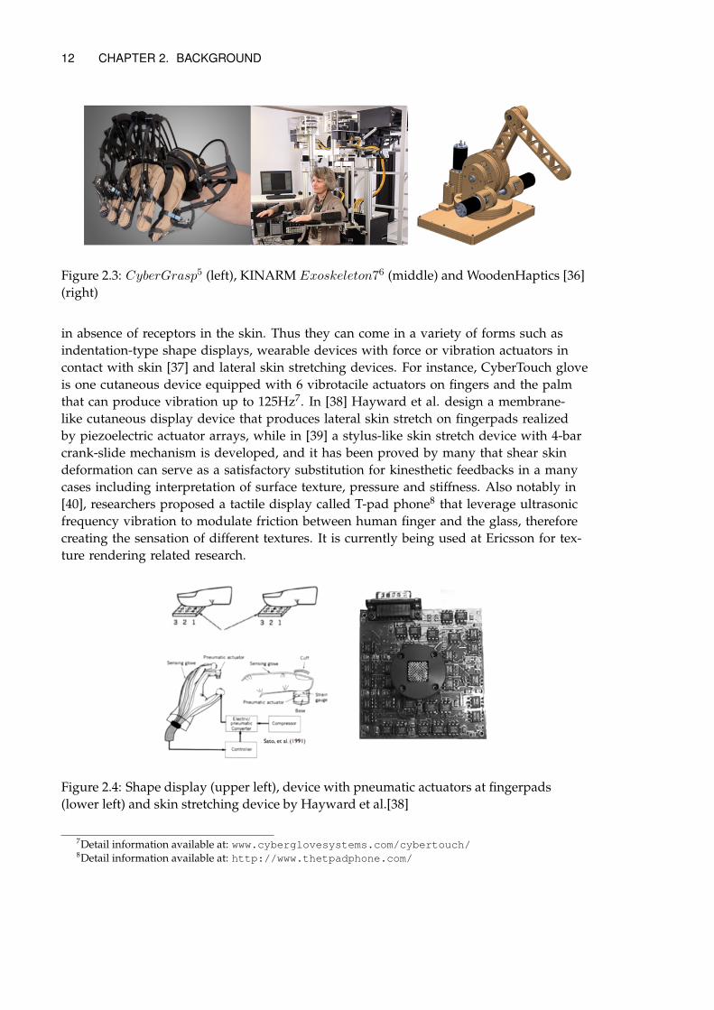
Existing haptic devices can be divided into kinesthetic and cutaneous devices, in thesame manner as we classify haptic perception. Kinesthetic devices use tools to medi-ate force and positions that are further passed onto human operators. Popular general-purpose kinesthetic devices include manipulandum type devices like the PHANToMseries (Phantom Desktop, Phantom Omni, Phantom Premium, now named 3D SystemsGeomagic series)1, Force Dimension Omega and Sigma series2, Falcon3 and Virtuose4;Grip/Grasp type devices like CyberGrasp5 and exoskeleton type like KINARM Exoskele-ton Lab6. [36] proposes a reconfigurable module-based wooden haptic device called Wood-enHaptics which is a manipulandum type kinesthetic device much cheaper than most ofits commercial counterparts and whose haptic fidelity is comparable to Phantom Desk-top. It also allows users to add sensors and vibrotactile actuators to improve perceptionof textures. The device group in Ericsson employ quite a few of these WoodenHaptics forresearch use.
The kinesthetic devices mentioned allow different ranges of motion from finger jointmovement to full arm movement pivoting at shoulder. Other important specificationsthat we may be concerned with include work space size, resolution, peak force allowance,DoF and update rate and so on. Table 2.3 gives a summary of those specifications ofsome devices.
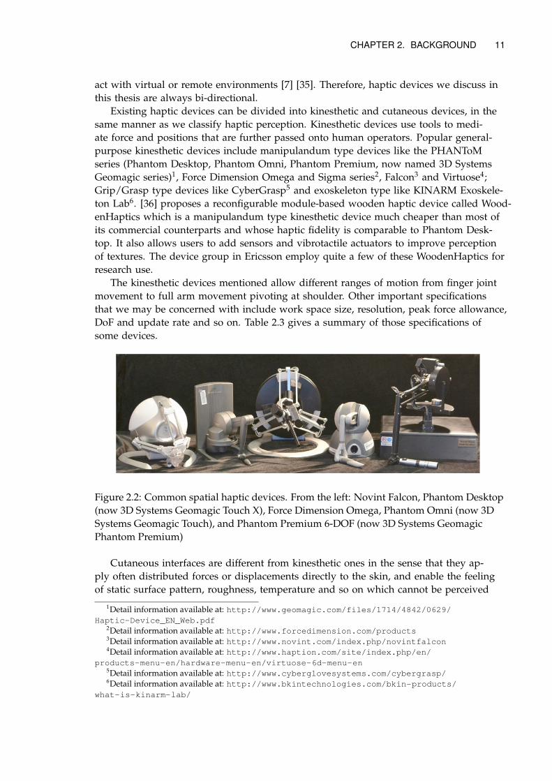
Figure 2.2: Common spatial haptic devices. From the left: Novint Falcon, Phantom Desktop(now 3D Systems Geomagic Touch X), Force Dimension Omega, Phantom Omni (now 3DSystems Geomagic Touch), and Phantom Premium 6-DOF (now 3D Systems GeomagicPhantom Premium)
Cutaneous interfaces are different from kinesthetic ones in the sense that they ap-ply often distributed forces or displacements directly to the skin, and enable the feelingof static surface pattern, roughness, temperature and so on which cannot be perceived
1Detail information available at: http://www.geomagic.com/files/1714/4842/0629/Haptic-Device_EN_Web.pdf
2Detail information available at: http://www.forcedimension.com/products3Detail information available at: http://www.novint.com/index.php/novintfalcon4Detail information available at: http://www.haption.com/site/index.php/en/
products-menu-en/hardware-menu-en/virtuose-6d-menu-en5Detail information available at: http://www.cyberglovesystems.com/cybergrasp/6Detail information available at: http://www.bkintechnologies.com/bkin-products/
what-is-kinarm-lab/
12 CHAPTER 2. BACKGROUND
Figure 2.3: CyberGrasp5 (left), KINARM Exoskeleton76 (middle) and WoodenHaptics [36](right)
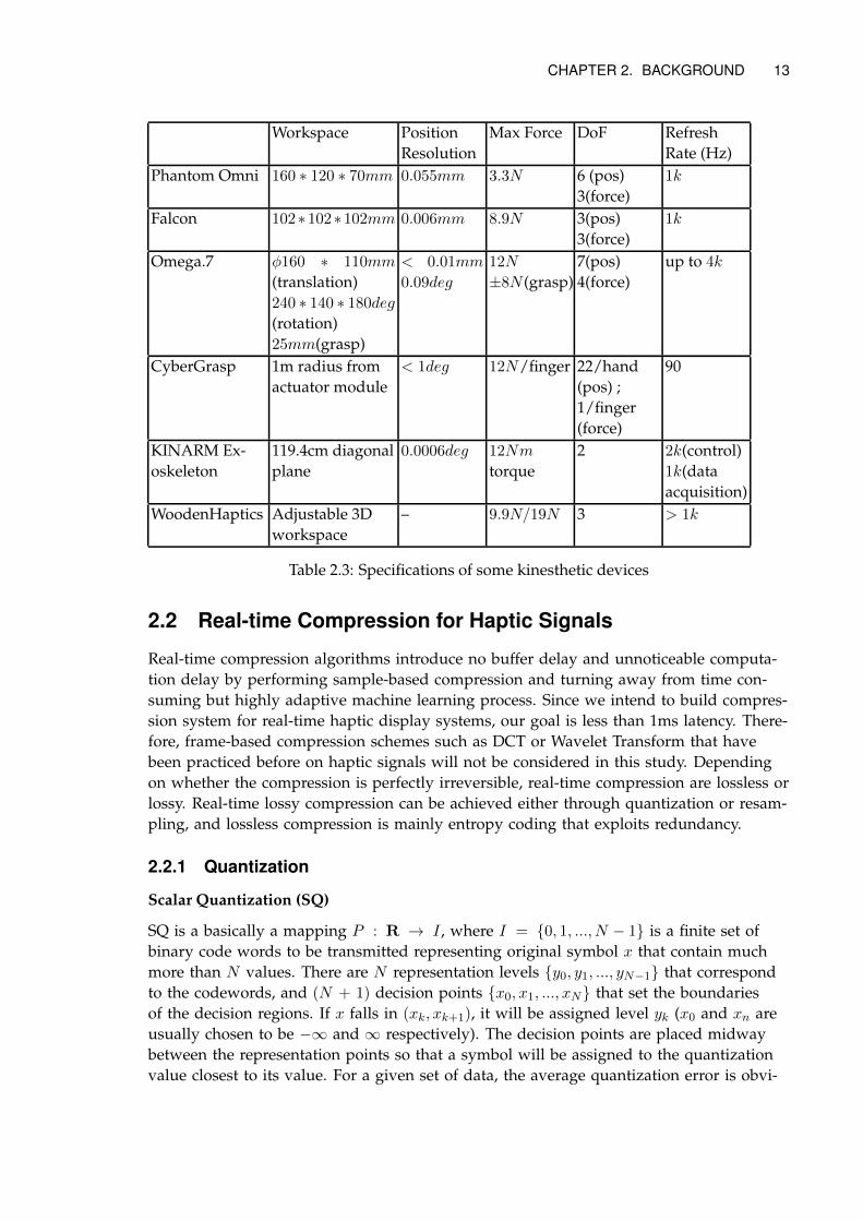
in absence of receptors in the skin. Thus they can come in a variety of forms such asindentation-type shape displays, wearable devices with force or vibration actuators incontact with skin [37] and lateral skin stretching devices. For instance, CyberTouch gloveis one cutaneous device equipped with 6 vibrotacile actuators on fingers and the palmthat can produce vibration up to 125Hz7. In [38] Hayward et al. design a membrane-like cutaneous display device that produces lateral skin stretch on fingerpads realizedby piezoelectric actuator arrays, while in [39] a stylus-like skin stretch device with 4-barcrank-slide mechanism is developed, and it has been proved by many that shear skindeformation can serve as a satisfactory substitution for kinesthetic feedbacks in a manycases including interpretation of surface texture, pressure and stiffness. Also notably in[40], researchers proposed a tactile display called T-pad phone8 that leverage ultrasonicfrequency vibration to modulate friction between human finger and the glass, thereforecreating the sensation of different textures. It is currently being used at Ericsson for tex-ture rendering related research.
Figure 2.4: Shape display (upper left), device with pneumatic actuators at fingerpads(lower left) and skin stretching device by Hayward et al.[38]
7Detail information available at: www.cyberglovesystems.com/cybertouch/8Detail information available at: http://www.thetpadphone.com/
CHAPTER 2. BACKGROUND 13
Workspace PositionResolution
Max Force DoF RefreshRate (Hz)
Phantom Omni 160 ∗ 120 ∗ 70mm 0.055mm 3.3N 6 (pos)3(force)
1k
Falcon 102∗102∗102mm 0.006mm 8.9N 3(pos)3(force)
1k
Omega.7 φ160 ∗ 110mm
(translation)240 ∗ 140 ∗ 180deg
(rotation)25mm(grasp)
< 0.01mm
0.09deg
12N
±8N (grasp)7(pos)4(force)
up to 4k
CyberGrasp 1m radius fromactuator module
< 1deg 12N/finger 22/hand(pos) ;1/finger(force)
90
KINARM Ex-oskeleton
119.4cm diagonalplane
0.0006deg 12Nm
torque2 2k(control)
1k(dataacquisition)
WoodenHaptics Adjustable 3Dworkspace
– 9.9N/19N 3 > 1k
Table 2.3: Specifications of some kinesthetic devices
2.2 Real-time Compression for Haptic Signals
Real-time compression algorithms introduce no buffer delay and unnoticeable computa-tion delay by performing sample-based compression and turning away from time con-suming but highly adaptive machine learning process. Since we intend to build compres-sion system for real-time haptic display systems, our goal is less than 1ms latency. There-fore, frame-based compression schemes such as DCT or Wavelet Transform that havebeen practiced before on haptic signals will not be considered in this study. Dependingon whether the compression is perfectly irreversible, real-time compression are lossless orlossy. Real-time lossy compression can be achieved either through quantization or resam-pling, and lossless compression is mainly entropy coding that exploits redundancy.
2.2.1 Quantization
Scalar Quantization (SQ)
SQ is a basically a mapping P : R → I , where I = {0, 1, ..., N − 1} is a finite set ofbinary code words to be transmitted representing original symbol x that contain muchmore than N values. There are N representation levels {y0, y1, ..., yN−1} that correspondto the codewords, and (N + 1) decision points {x0, x1, ..., xN} that set the boundariesof the decision regions. If x falls in (xk, xk+1), it will be assigned level yk (x0 and xn areusually chosen to be −∞ and ∞ respectively). The decision points are placed midwaybetween the representation points so that a symbol will be assigned to the quantizationvalue closest to its value. For a given set of data, the average quantization error is obvi-
14 CHAPTER 2. BACKGROUND
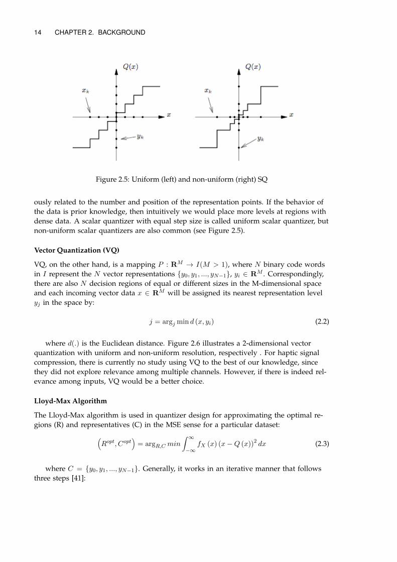
Figure 2.5: Uniform (left) and non-uniform (right) SQ
ously related to the number and position of the representation points. If the behavior ofthe data is prior knowledge, then intuitively we would place more levels at regions withdense data. A scalar quantizer with equal step size is called uniform scalar quantizer, butnon-uniform scalar quantizers are also common (see Figure 2.5).
Vector Quantization (VQ)
VQ, on the other hand, is a mapping P : RM → I(M > 1), where N binary code wordsin I represent the N vector representations {y0, y1, ..., yN−1}, yi ∈ RM . Correspondingly,there are also N decision regions of equal or different sizes in the M-dimensional spaceand each incoming vector data x ∈ RM will be assigned its nearest representation levelyj in the space by:
j = argj min d (x, yi) (2.2)
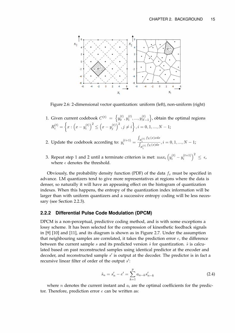
where d(.) is the Euclidean distance. Figure 2.6 illustrates a 2-dimensional vectorquantization with uniform and non-uniform resolution, respectively . For haptic signalcompression, there is currently no study using VQ to the best of our knowledge, sincethey did not explore relevance among multiple channels. However, if there is indeed rel-evance among inputs, VQ would be a better choice.
Lloyd-Max Algorithm
The Lloyd-Max algorithm is used in quantizer design for approximating the optimal re-gions (R) and representatives (C) in the MSE sense for a particular dataset:(
Ropt, Copt)
= argR,C min
∫ ∞−∞
fX (x) (x−Q (x))2 dx (2.3)
where C = {y0, y1, ..., yN−1}. Generally, it works in an iterative manner that followsthree steps [41]:
CHAPTER 2. BACKGROUND 15
Figure 2.6: 2-dimensional vector quantization: uniform (left), non-uniform (right)
1. Given current codebook C(t) ={y(t)0 , y
(t)1 , ..., y
(t)N−1
}, obtain the optimal regions
R(t)i =
{x :(x− y(t)i
)2≤(x− y(t)j
)2, j 6= i
}, i = 0, 1, ..., N − 1;
2. Update the codebook according to: y(t+1)i =
∫R(t)i
fX(x)xdx∫R(t)i
fX(x)dx, i = 0, 1, ..., N − 1;
3. Repeat step 1 and 2 until a terminate criterion is met: maxi(y(t)i − y
(t+1)i
)2≤ ε,
where ε denotes the threshold.
Obviously, the probability density function (PDF) of the data fx must be specified inadvance. LM quantizers tend to give more representatives at regions where the data isdenser, so naturally it will have an appeasing effect on the histogram of quantizationindexes. When this happens, the entropy of the quantization index information will belarger than with uniform quantizers and a successive entropy coding will be less neces-sary (see Section 2.2.3).
2.2.2 Differential Pulse Code Modulation (DPCM)
DPCM is a non-perceptual, predictive coding method, and is with some exceptions alossy scheme. It has been selected for the compression of kinesthetic feedback signalsin [9] [10] and [11], and its diagram is shown as in Figure 2.7. Under the assumptionthat neighbouring samples are correlated, it takes the prediction error e, the differencebetween the current sample s and its predicted version s for quantization. s is calcu-lated based on past reconstructed samples using identical predictor at the encoder anddecoder, and reconstructed sample s′ is output at the decoder. The predictor is in fact arecursive linear filter of order of the output s′:
sn = s′n − e′ =p∑
k=1
an−ks′n−k (2.4)
where n denotes the current instant and ai are the optimal coefficients for the predic-tor. Therefore, prediction error e can be written as:
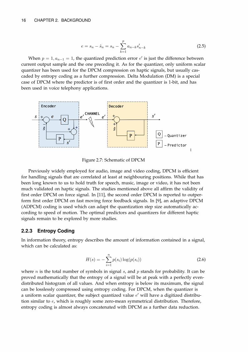
16 CHAPTER 2. BACKGROUND
e = sn − sn = sn −p∑
k=1
an−ks′n−k (2.5)
When p = 1, an−1 = 1, the quantized prediction error e′ is just the difference betweencurrent output sample and the one preceding it. As for the quantizer, only uniform scalarquantizer has been used for the DPCM compression on haptic signals, but usually cas-caded by entropy coding as a further compression. Delta Modulation (DM) is a specialcase of DPCM where the predictor is of first order and the quantizer is 1-bit, and hasbeen used in voice telephony applications.
Figure 2.7: Schematic of DPCM
Previously widely employed for audio, image and video coding, DPCM is efficientfor handling signals that are correlated at least at neighbouring positions. While that hasbeen long known to us to hold truth for speech, music, image or video, it has not beenmuch validated on haptic signals. The studies mentioned above all affirm the validity offirst order DPCM on force signal. In [11], the second order DPCM is reported to outper-form first order DPCM on fast moving force feedback signals. In [9], an adaptive DPCM(ADPCM) coding is used which can adapt the quantization step size automatically ac-cording to speed of motion. The optimal predictors and quantizers for different hapticsignals remain to be explored by more studies.
2.2.3 Entropy Coding
In information theory, entropy describes the amount of information contained in a signal,which can be calculated as:
H(s) = −n∑i=1
p(si) log(p(si)) (2.6)
where n is the total number of symbols in signal s, and p stands for probability. It can beproved mathematically that the entropy of a signal will be at peak with a perfectly even-distributed histogram of all values. And when entropy is below its maximum, the signalcan be losslessly compressed using entropy coding. For DPCM, when the quantizer isa uniform scalar quantizer, the subject quantized value e′ will have a digitized distribu-tion similar to e, which is roughly some zero-mean symmetrical distribution. Therefore,entropy coding is almost always concatenated with DPCM as a further data reduction.
CHAPTER 2. BACKGROUND 17
Popular entropy coding schemes that have been applied to haptic signals include Huff-man Coding and Golomb-Rice Coding [10] [11].
Huffman Coding assigns code with different lengths to each symbol, based on theirstatistical probability. Symbols with larger probabilities of occurrence are supposed to useshorter codewords than those that does not commonly appear. It adopts a bottom-up treeapproach to choose the representation for each symbol such that a prefix code in whichone codeword representing a symbol is never a prefix of the one representing any othersymbol. Huffman coding is considered optimal among all entropy codes when a sourceconsists of unrelated symbols with a known probability distribution, and thus often fol-lows after DPCM, given that the predictor in DPCM will lead to prediction errors withlittle correlation.
Golomb-Rice Coding divides a symbol by a constant M to get the quotient q and re-mainder r. Later q is encoded using unary coding and r is encoded using truncated bi-nary coding, and the two parts are concatenated to form the codeword for the symbol.The codeword length is only dependent on the magnitude of the symbol and constantM , and therefore is highly suitable for situations in which small values occur much morelikely than large values.
In general, entropy coding is based on the assumption that the histogram of the inputdata is highly uneven. If it is not the case, the entropy of the data would be renderedhigh and there would be little motivation in using entropy coding for reduction. In thisthesis, a different path which adopts histogram equalization plus sparse coding will beused instead of entropy coding, which will be described in Chapter 3.
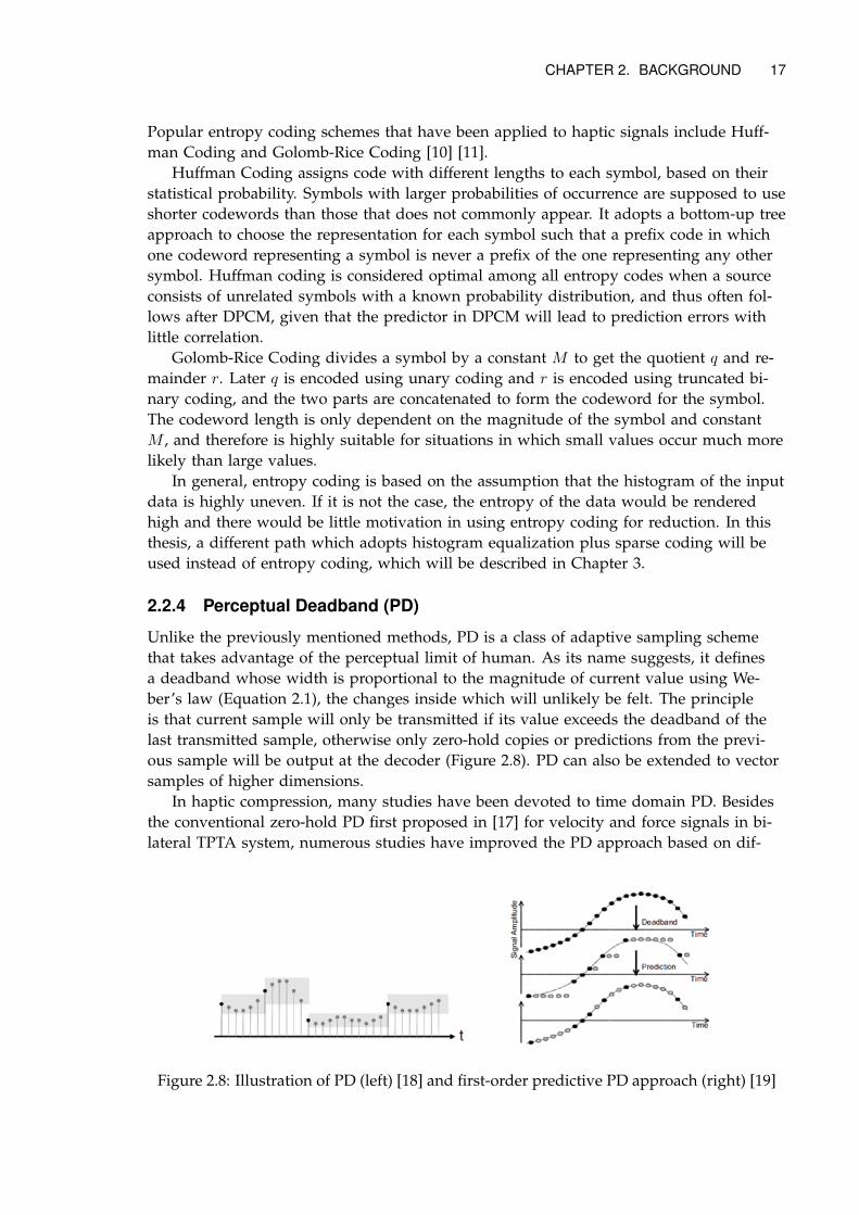
2.2.4 Perceptual Deadband (PD)
Unlike the previously mentioned methods, PD is a class of adaptive sampling schemethat takes advantage of the perceptual limit of human. As its name suggests, it definesa deadband whose width is proportional to the magnitude of current value using We-ber’s law (Equation 2.1), the changes inside which will unlikely be felt. The principleis that current sample will only be transmitted if its value exceeds the deadband of thelast transmitted sample, otherwise only zero-hold copies or predictions from the previ-ous sample will be output at the decoder (Figure 2.8). PD can also be extended to vectorsamples of higher dimensions.
In haptic compression, many studies have been devoted to time domain PD. Besidesthe conventional zero-hold PD first proposed in [17] for velocity and force signals in bi-lateral TPTA system, numerous studies have improved the PD approach based on dif-
Figure 2.8: Illustration of PD (left) [18] and first-order predictive PD approach (right) [19]
18 CHAPTER 2. BACKGROUND
ferent prediction algorithms. Among them, first-order prediction PD [18] is the simplestform of prediction which states that sample is only transmitted when the difference be-tween the current value and the linearly predicted value of the current value is out of thedeadband of the predicted value. The rest of sample values between the two updates arelinearly extrapolated locally at the decoder using the slope information from two latestupdates.
Apparently, the underlying implication of this prediction is that the change of the sig-nal is unidirectional within a short duration, and therefore it will only outperform zero-hold PD method on smoothly-varying data.
There are other considerations on haptic PD. Human operator is not simply a passivereceiver of information in a haptic TPTA system but also an active participator, and psy-chophysical experiments have validated that the perceptual ability of human is relatedto their activeness and level of attention. Therefore, Weber’s law may not be applicableto all cases and the PD ratio can be purposely designed to be variable [24]. In this thesis,the PD method for compression will not be incorporated explicitly. Instead, we make itpossible to be embedded into the system we propose that mainly adopts non-perceptualcompression.
2.3 Performance Evaluation Methods
As haptic compression schemes can be either non-perceptual like the conventional DPCMmethod or perceptual like the PD method, the evaluation of performance should also di-vide between objective and subjective measurements. The former looks at only calcula-tions when judging the system, while the latter relies on subjective reports from actualhuman operators and is hard to quantize.
2.3.1 Objective Measurements
Signal Distortion
Signal-to-Noise Ratio (SNR) is one of the most common methods to measure signal dis-tortion, which basically is the ratio between the energy of the original signal and that ofthe difference between the original and the reconstruction expressed in decibels:
SNRdB = 10 log10(PsignalPnoise
) = 10 log10(
∑Ni=1 s(i)
2∑Ni=1(s(i)− s(i))2
) (2.7)
where s and s represent original and reconstructed signal in time domain, respec-tively, and N is the total number of samples. While equation 2.7 only represents the av-erage signal distortion over a long time, we can always chunk up the signal and calcu-late the average SNR on segments (SegSNR):
SegSNRdB =1
N
N∑j=1
10 log10(
∑Mi=1 s(jM + i)2∑M
i=1(s(jM + i)− s(jM + i))2) (2.8)
Where N is the number of frame and M is the frame length. In this way, the short-term variation in signal distortion will also influence the overall SNR.
CHAPTER 2. BACKGROUND 19
Although we care much about time-domain signal distortion of haptic signals, thefrequency domain matters a lot for vibrotactile signals in particular. In Section 2.1.1 it ismentioned that frequency component plays the dominant role when perceiving rapidlyfluctuating vibrotactile signals, and deadband in the frequency dimension also exists.Since the system should also be suitable for vibrotactile signal transmission, spectral dis-tortion is something we should be cautious when judging the system. One measurementof spectral distortion is known as the log-spectral distance (LSD):
DLS =
√1
2π
∫ π
−π[10 log10
P (ω)
P (ω)]2dω (2.9)
where P (ω) and P (ω) are the power spectra of the original and reconstructed signal, re-spectively. The larger the distance is, the more the distortion in the frequency domain.Again, LSD can also be calculated on a segment basis and average over all segments.
In this thesis, we use SNR results as the main criterion for signal distortion, since weare designing a real-time compression system that can exert a direct influence on SNR.But we will also calculate and compare spectral distortion and check on the shape of thespectra. Then we should be able to tell the SNR threshold for our system at which thespectral distortion is also acceptable.
Compression Efficiency
The efficiency of a compression algorithm lies in its power of data reduction. Usuallycompression ratio (CR) or data rate savings (DRS) is used to describe such power:
CR =uncompressed data in bps
compressed data in bps(2.10)
DRS = 1− 1
CR(2.11)
Apparently, there is a trade-off between compression efficiency and signal distortion.In networks with high traffic, we tend to weigh efficiency over distortion, while othertimes we focus more on reconstruction quality. Therefore, people take care of both speci-fications by drawing SNR-DRS coordinates and find the proper parameters for compres-sion systems in regions that suit their specific circumstances.
2.3.2 Subjective Measurements
Despite the fact that objective measurements offer a clearly quantifiable evaluation of thereconstruction quality of compression algorithms, these numbers cannot have our entirefaith. As the ultimate goal of designing a haptic codec or any audio or visual codec isto let human operators barely feel any degradation in the signal compared to an uncom-pressed version, it makes more sense to have the final say entitled to human. Therefore,subjective tests are widely recognized as the most reliable way for evaluating codecs, es-pecially for the low bitrate ones.
There has been quite many standardized subjective tests for audio quality, such asMUSHRA (Multiple Stimuli with Hidden Reference and Anchor) defined by ITU-R rec-ommendation BS.1534-39 and MOS (Mean Opinion Score) specified by ITU-T P.80010. But
9Detail information available at: http://www.itu.int/rec/R-REC-BS.1534-3-201510-I/en10Detail information available at: http://www.itu.int/rec/T-REC-P.800-199608-I/en

20 CHAPTER 2. BACKGROUND
haptic coding is a relatively new field with no such standards available. In fact, a subjec-tive test standard for haptic systems would be more complex due to the bilateral natureof and drastic differences among haptic activities. So far, researchers have used diver-sified methods for subjective tests inspired either by ITU standards for audio codecs orby other psychophysical experiments, as covered in Section 1.2. In this thesis, subjectivestudies are not conducted. Only objective measurements are used complemented by di-rect observation of waveform.
Chapter 3
The Compression System
3.1 System Overview
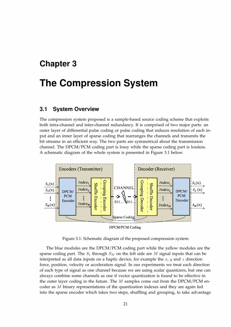
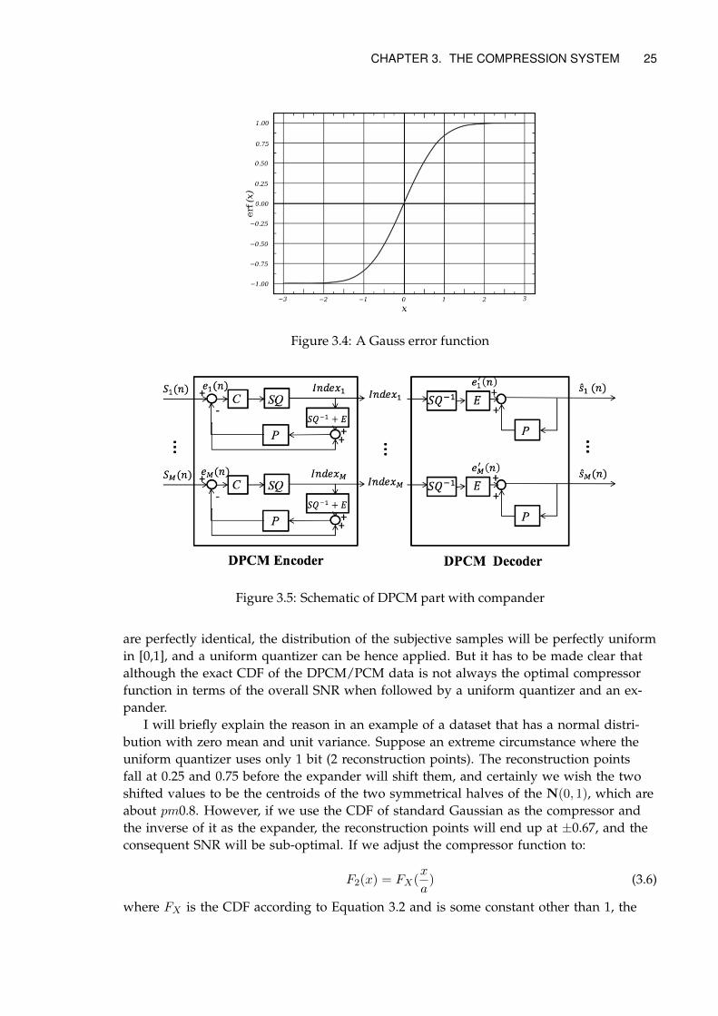
The compression system proposed is a sample-based source coding scheme that exploitsboth intra-channel and inter-channel redundancy. It is comprised of two major parts: anouter layer of differential pulse coding or pulse coding that reduces resolution of each in-put and an inner layer of sparse coding that rearranges the channels and transmits thebit streams in an efficient way. The two parts are symmetrical about the transmissionchannel. The DPCM/PCM coding part is lossy while the sparse coding part is lossless.A schematic diagram of the whole system is presented in Figure 3.1 below.
Figure 3.1: Schematic diagram of the proposed compression system
The blue modules are the DPCM/PCM coding part while the yellow modules are thesparse coding part. The S1 through SM on the left side are M signal inputs that can beinterpreted as all data inputs on a haptic device, for example the x, y and z directionforce, position, velocity or acceleration signal. In our experiments we treat each directionof each type of signal as one channel because we are using scalar quantizers, but one canalways combine some channels as one if vector quantization is found to be effective inthe outer layer coding in the future. The M samples come out from the DPCM/PCM en-coder as M binary representations of the quantization indexes and they are again fedinto the sparse encoder which takes two steps, shuffling and grouping, to take advantage
21
22 CHAPTER 3. THE COMPRESSION SYSTEM
of inter-channel redundancy and transform those binary notations into a more concisesingle bit stream. Since we do not consider channel coding in this study, the transmissionchannel between the transmitter and the receiver is assumed to be ideally error-free andtransparent, which means the data immediately on two sides of the transmission channelare identical and transmission latency is neglected. Therefore, the bit stream for one sam-ple interval arrives at the receiver’s sparse decoder exactly the same as how it leaves thetransmitter’s sparse encoder. The sparse decoder then recovers the quantization indexesas well as their original channel locations and finally the DPCM/PCM decoder outputsthe M reconstructed signal samples. The following sections 3.2 and 3.3 will dissect thesystem into two layers and describe them accordingly.
3.2 DPCM/PCM Coding Layer
This is the outer layer of the compression system that takes in all input signal samplesat the transmitter and outputs all reconstructed samples at the receiver, as the two partscolored in blue in Figure 3.1. The structure of basic DPCM has been illustrated in Fig-ure 2.7, and our current scheme is no more than parallel versions of those basic struc-tures. Any of the structures can be replaced by PCM effortlessly when necessary. Sincethe inner sparse coding layer and the transmission channel are assumed to be losslessand transparent, a simplified schematic which skip those parts will be used in the restof this section. The DPCM/PCM coding layer is the only lossy part in the system, so weexperiment with different designs at both the quantizer and the predictor to see the SNRperformance at several bitrates.
3.2.1 Quantizer Design
Previous studies that use DPCM for haptic data reduction all resorted to uniform scalarquantizer, with either fixed or adaptive codebooks. This is often for the sake of simplicityor attaching entropy coding with variable length code words. If the chosen predictor per-forms well on the data, the consequent prediction error will be substantially reduced inrange and correlation compared to the original sample and thus will have a distributioncentralized around zero value. We can then assign the shortest code word to the indexthat occurs significantly more than others.
However, we are designing a compression system for multiple channels, and we fur-ther reduce the data rate through a means other than entropy coding, so there is no di-rect motivation in sticking to uniform quantizer step and fixed codebook. Instead we canhave flexible quantization and try to maximize SNR at certain bitrates at this stage.
Non-uniform Scalar Quantizer with Lloyd-Max Codebook
The first plan for the quantizer in DPCM (or PCM) we propose is to train a Lloyd-Maxcodebook for each input channel, which has been described in Section 2.2.1. This can re-sult in non-uniform quantization steps and ideally optimal representation points for thedata from a particular channel in terms of MSE, but not a sparse histogram of quantiza-tion index. The training process can be either offline or online, leading to fixed or vary-ing codebooks. In this thesis, the codebooks are trained offline since we do not have ac-cess to fresh data from haptic devices at the moment, and we only train one codebook
CHAPTER 3. THE COMPRESSION SYSTEM 23
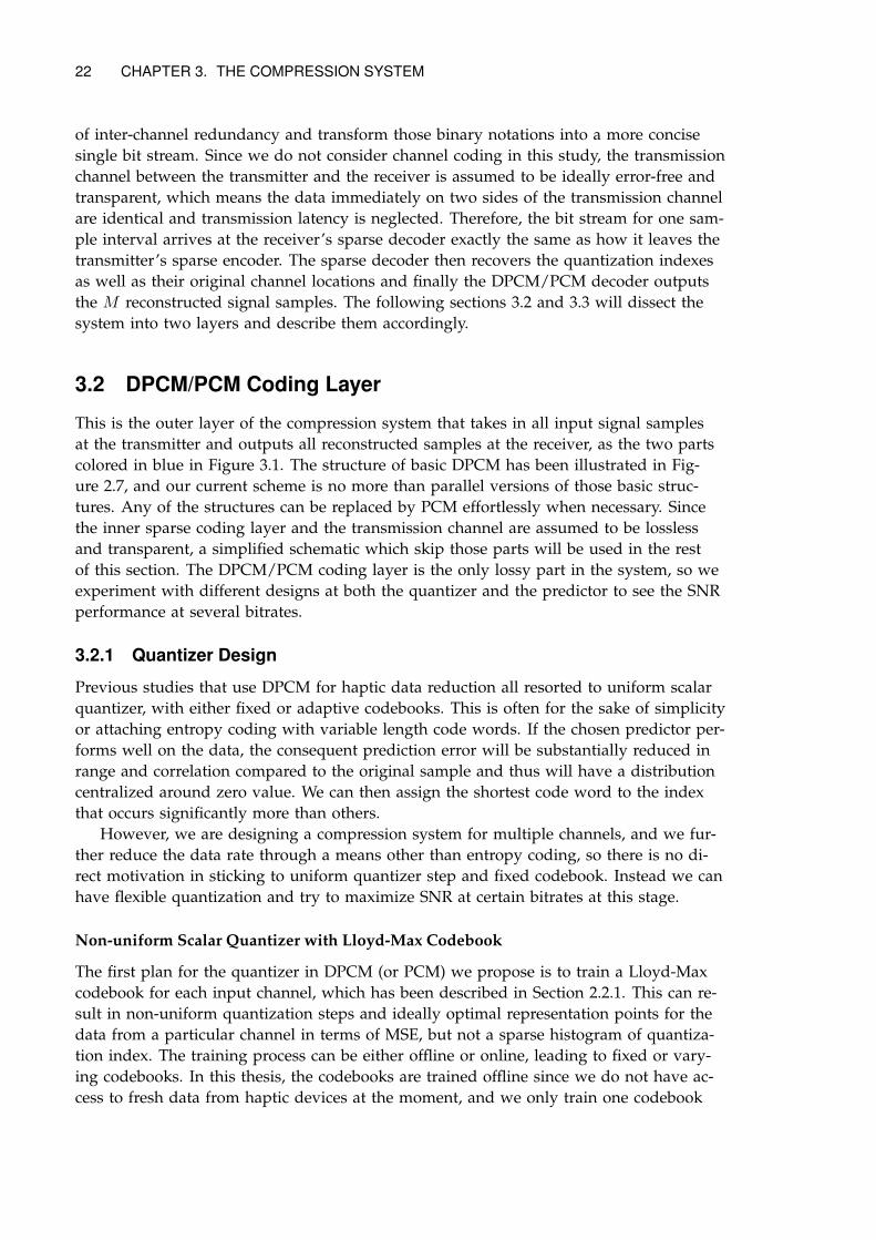
for one type of channel, i.e. three for force signal and three for acceleration signal (corre-spond to x, y, z direction). Figure 3.2 is a schematic view of this design.
Figure 3.2: Schematic of DPCM part with Lloyd-Max codebook
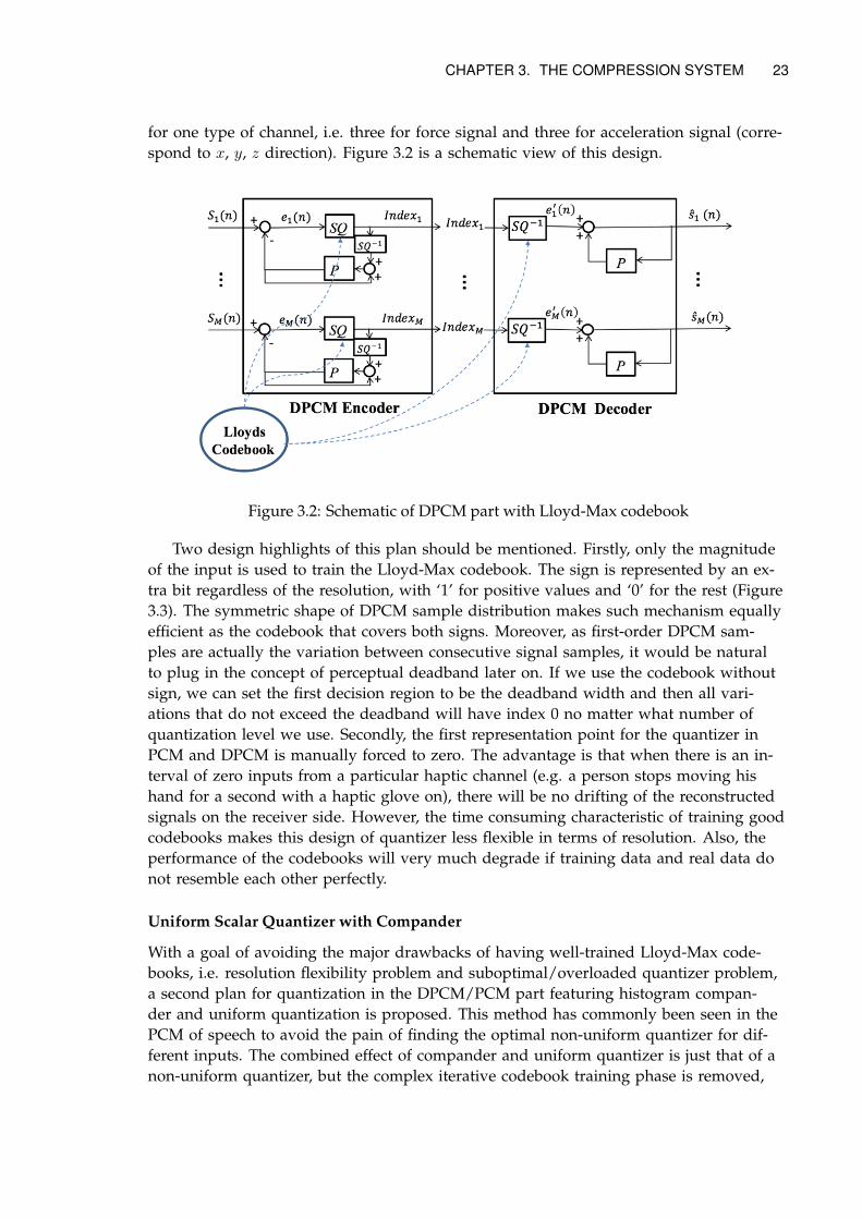
Two design highlights of this plan should be mentioned. Firstly, only the magnitudeof the input is used to train the Lloyd-Max codebook. The sign is represented by an ex-tra bit regardless of the resolution, with ‘1’ for positive values and ‘0’ for the rest (Figure3.3). The symmetric shape of DPCM sample distribution makes such mechanism equallyefficient as the codebook that covers both signs. Moreover, as first-order DPCM sam-ples are actually the variation between consecutive signal samples, it would be naturalto plug in the concept of perceptual deadband later on. If we use the codebook withoutsign, we can set the first decision region to be the deadband width and then all vari-ations that do not exceed the deadband will have index 0 no matter what number ofquantization level we use. Secondly, the first representation point for the quantizer inPCM and DPCM is manually forced to zero. The advantage is that when there is an in-terval of zero inputs from a particular haptic channel (e.g. a person stops moving hishand for a second with a haptic glove on), there will be no drifting of the reconstructedsignals on the receiver side. However, the time consuming characteristic of training goodcodebooks makes this design of quantizer less flexible in terms of resolution. Also, theperformance of the codebooks will very much degrade if training data and real data donot resemble each other perfectly.
Uniform Scalar Quantizer with Compander
With a goal of avoiding the major drawbacks of having well-trained Lloyd-Max code-books, i.e. resolution flexibility problem and suboptimal/overloaded quantizer problem,a second plan for quantization in the DPCM/PCM part featuring histogram compan-der and uniform quantization is proposed. This method has commonly been seen in thePCM of speech to avoid the pain of finding the optimal non-uniform quantizer for dif-ferent inputs. The combined effect of compander and uniform quantizer is just that of anon-uniform quantizer, but the complex iterative codebook training phase is removed,
24 CHAPTER 3. THE COMPRESSION SYSTEM
Figure 3.3: Comparison of signed and unsigned codebook (2-bit resolution)
while the price is the computational cost for the compander1. Instead of a predefinedcodebook for each channel, it first uses a compressor, a mathematic transformation thatmaps all DPCM/PCM samples to a known interval (e.g. [0, 1]). Such transformation isnot difficult to conceive. The cumulative distribution function (CDF) of the data sampleswill exactly serve the purpose, for it maps each sample value to its corresponding per-centile in CDF, which is between 0 and 1. For example, if the data is subjected to someGaussian distribution with zero mean N(0, σ):
fX(x) =1√2πσ
exp(− x2
2σ2) (3.1)
then the compressor function can be:
FX(x) =
∫ x
−∞fX(u)du =
1
2+
1
2erf(
x√2σ
) (3.2)
where erf(.) is a notation of the Gauss error function:
erf(x) =2√π
∫ x
0e−t
2dt (3.3)
After transforming the DPCM/PCM samples with a compressor such as in equa-tion 3.2, the histogram of the data will be greatly equalized and the range is strictly con-strained between 0 and 1. The processed samples then go to the uniform quantizer set ata resolution of N bits that assign each sample its quantization index:
I =⌊x · 2N
⌋(3.4)
where x represents the sample after the compressor. On the receiver side, the index ismapped to the reconstruction point value through:
x =2I + 1
2N+1(3.5)
And finally the original sample is recovered through an expander, the inverse func-tion of the compressor. Its schematic is shown in Figure 3.5. C and E represent the com-pressor and expander, respectively. If the compressor function and the CDF of the data
1http://ocw.mit.edu/courses/aeronautics-and-astronautics/16-36-communication-systems-engineering-spring-2009/lecture-notes/MIT16_36s09_lec04.pdf
CHAPTER 3. THE COMPRESSION SYSTEM 25
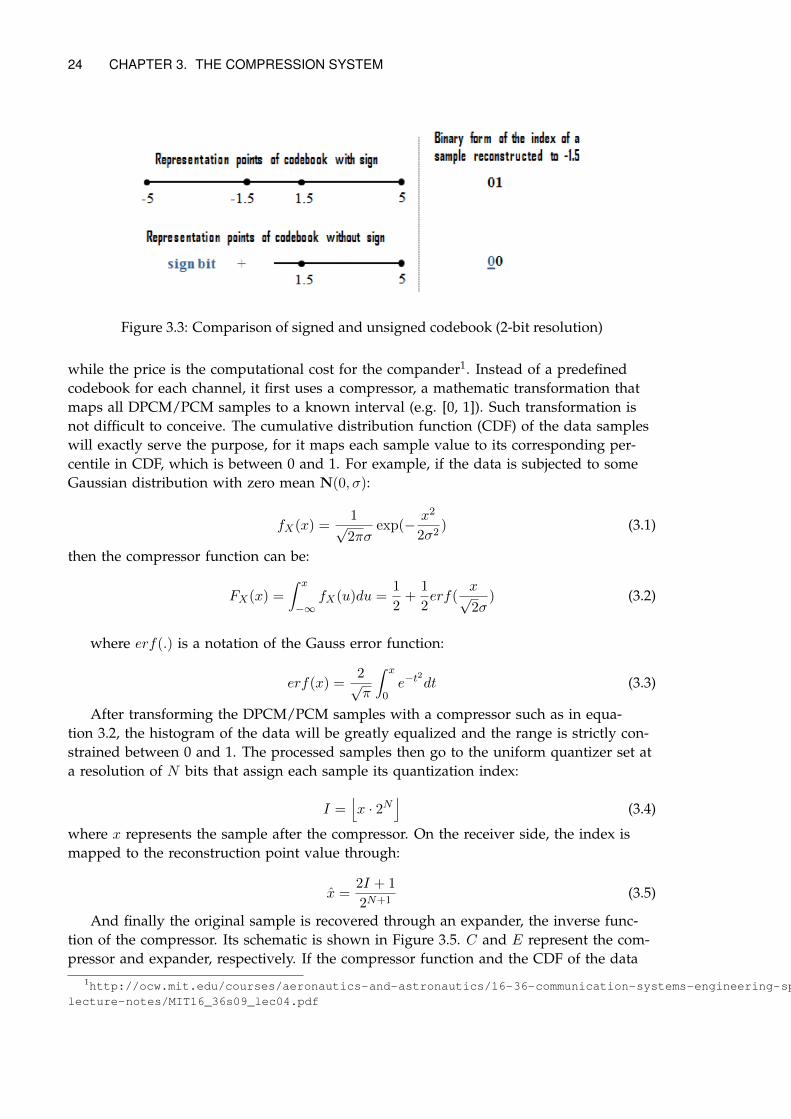
Figure 3.4: A Gauss error function
Figure 3.5: Schematic of DPCM part with compander
are perfectly identical, the distribution of the subjective samples will be perfectly uniformin [0,1], and a uniform quantizer can be hence applied. But it has to be made clear thatalthough the exact CDF of the DPCM/PCM data is not always the optimal compressorfunction in terms of the overall SNR when followed by a uniform quantizer and an ex-pander.
I will briefly explain the reason in an example of a dataset that has a normal distri-bution with zero mean and unit variance. Suppose an extreme circumstance where theuniform quantizer uses only 1 bit (2 reconstruction points). The reconstruction pointsfall at 0.25 and 0.75 before the expander will shift them, and certainly we wish the twoshifted values to be the centroids of the two symmetrical halves of the N(0, 1), which areabout pm0.8. However, if we use the CDF of standard Gaussian as the compressor andthe inverse of it as the expander, the reconstruction points will end up at ±0.67, and theconsequent SNR will be sub-optimal. If we adjust the compressor function to:
F2(x) = FX(x
a) (3.6)
where FX is the CDF according to Equation 3.2 and is some constant other than 1, the
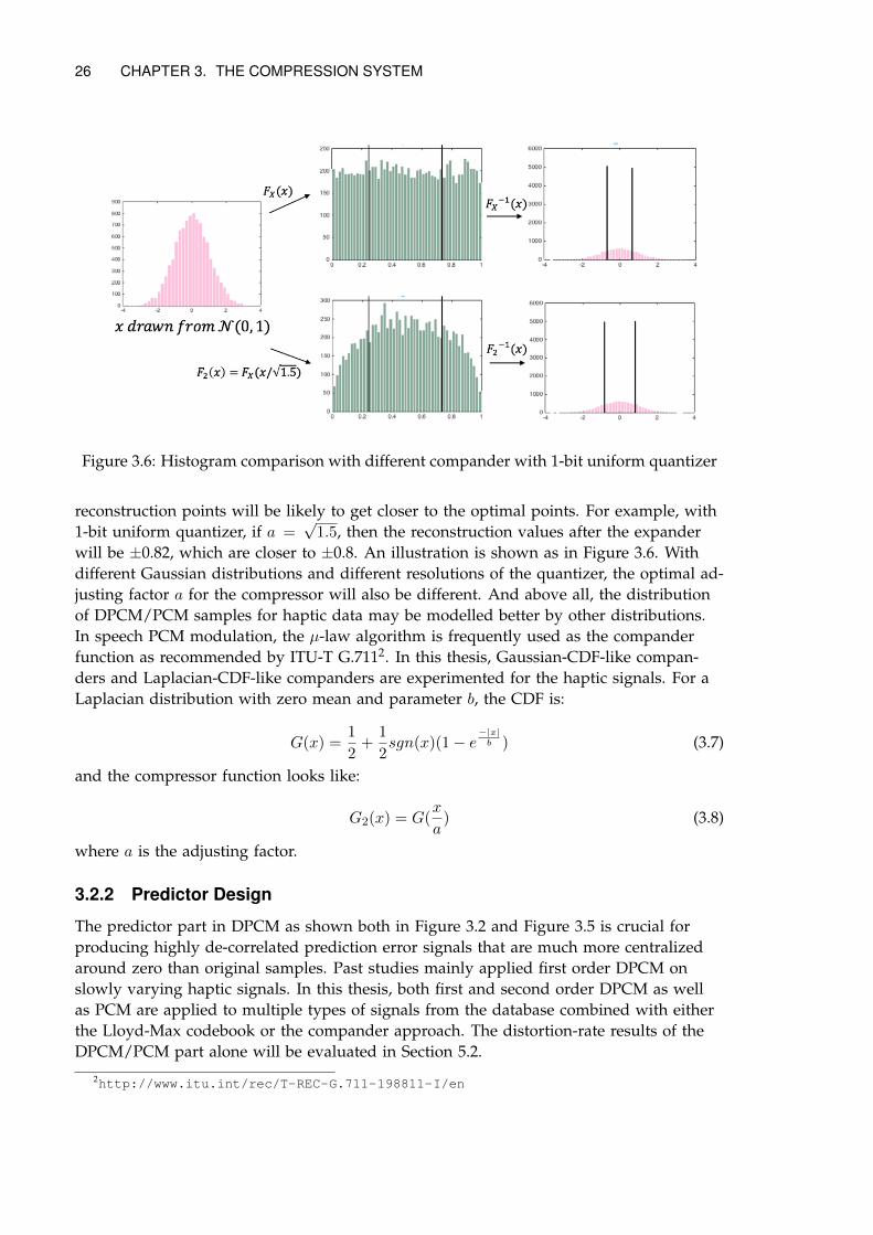
26 CHAPTER 3. THE COMPRESSION SYSTEM
Figure 3.6: Histogram comparison with different compander with 1-bit uniform quantizer
reconstruction points will be likely to get closer to the optimal points. For example, with1-bit uniform quantizer, if a =
√1.5, then the reconstruction values after the expander
will be ±0.82, which are closer to ±0.8. An illustration is shown as in Figure 3.6. Withdifferent Gaussian distributions and different resolutions of the quantizer, the optimal ad-justing factor a for the compressor will also be different. And above all, the distributionof DPCM/PCM samples for haptic data may be modelled better by other distributions.In speech PCM modulation, the µ-law algorithm is frequently used as the companderfunction as recommended by ITU-T G.7112. In this thesis, Gaussian-CDF-like compan-ders and Laplacian-CDF-like companders are experimented for the haptic signals. For aLaplacian distribution with zero mean and parameter b, the CDF is:
G(x) =1
2+
1
2sgn(x)(1− e
−|x|b ) (3.7)
and the compressor function looks like:
G2(x) = G(x
a) (3.8)
where a is the adjusting factor.
3.2.2 Predictor Design
The predictor part in DPCM as shown both in Figure 3.2 and Figure 3.5 is crucial forproducing highly de-correlated prediction error signals that are much more centralizedaround zero than original samples. Past studies mainly applied first order DPCM onslowly varying haptic signals. In this thesis, both first and second order DPCM as wellas PCM are applied to multiple types of signals from the database combined with eitherthe Lloyd-Max codebook or the compander approach. The distortion-rate results of theDPCM/PCM part alone will be evaluated in Section 5.2.
2http://www.itu.int/rec/T-REC-G.711-198811-I/en
CHAPTER 3. THE COMPRESSION SYSTEM 27
3.3 Sparse Coding Part
This is the inner part of the entire compression system, labelled yellow in Figure 3.1. Itis lossless because it further reduces data transmission only by mitigating the chance oftransmitting zero quantization indexes (which also have zero reconstruction values andthus meaningless to transmit with full bits) from all input channels. In order to indicatewhether to transmit a sample, we need flag bits to label the channels. However, chancesare the proportion of input channels with zero indexes is low and one flag bit per chan-nel is deemed superfluous. Since we also assume a bunch of inputs in our haptic appli-cation, we decide to divide the channels into small groups and each group is given oneflag bit. The flag bit of a group is 0 only in the condition that all inputs in that grouphave zero indexes at one instant.
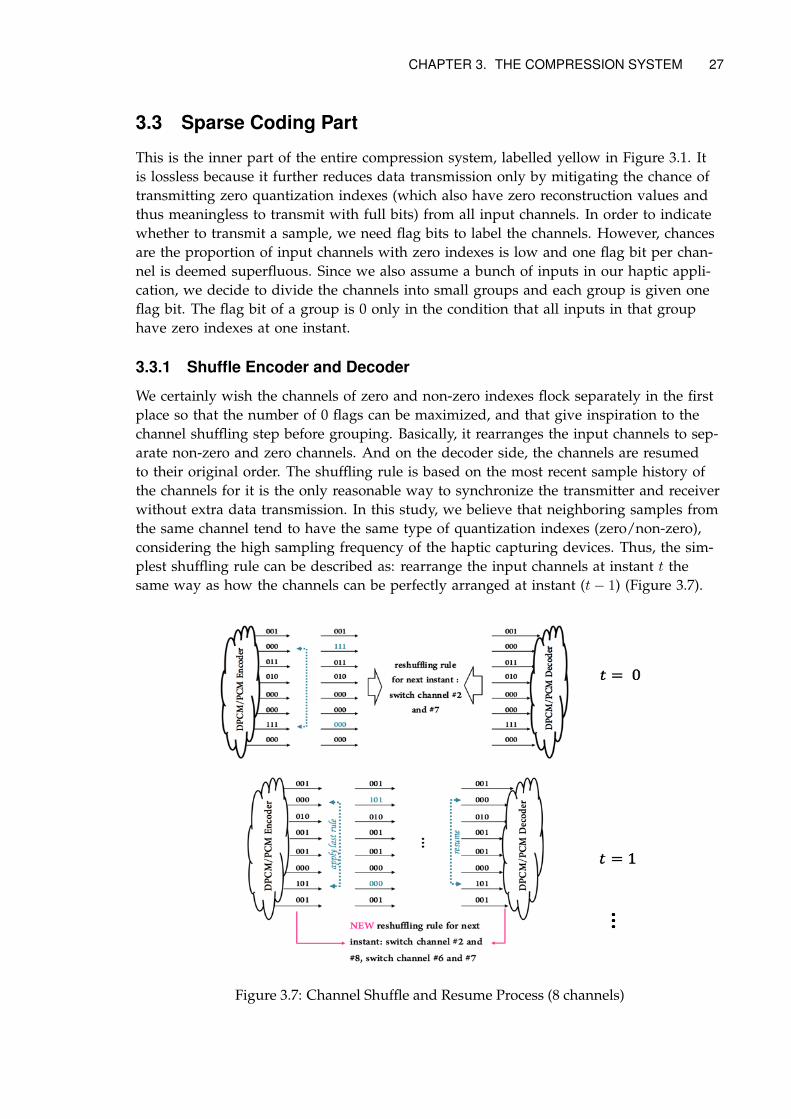
3.3.1 Shuffle Encoder and Decoder
We certainly wish the channels of zero and non-zero indexes flock separately in the firstplace so that the number of 0 flags can be maximized, and that give inspiration to thechannel shuffling step before grouping. Basically, it rearranges the input channels to sep-arate non-zero and zero channels. And on the decoder side, the channels are resumedto their original order. The shuffling rule is based on the most recent sample history ofthe channels for it is the only reasonable way to synchronize the transmitter and receiverwithout extra data transmission. In this study, we believe that neighboring samples fromthe same channel tend to have the same type of quantization indexes (zero/non-zero),considering the high sampling frequency of the haptic capturing devices. Thus, the sim-plest shuffling rule can be described as: rearrange the input channels at instant t thesame way as how the channels can be perfectly arranged at instant (t− 1) (Figure 3.7).
Figure 3.7: Channel Shuffle and Resume Process (8 channels)
28 CHAPTER 3. THE COMPRESSION SYSTEM
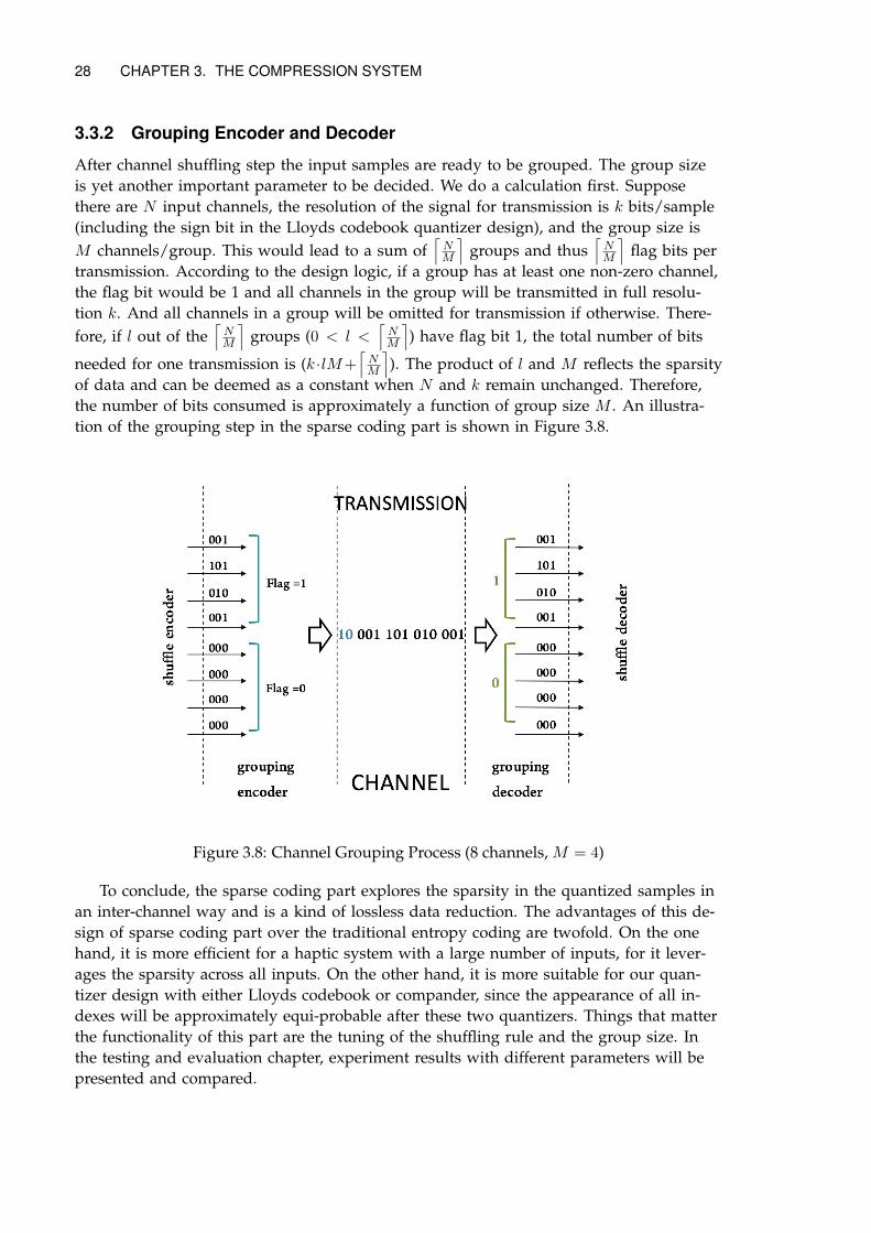
3.3.2 Grouping Encoder and Decoder
After channel shuffling step the input samples are ready to be grouped. The group sizeis yet another important parameter to be decided. We do a calculation first. Supposethere are N input channels, the resolution of the signal for transmission is k bits/sample(including the sign bit in the Lloyds codebook quantizer design), and the group size isM channels/group. This would lead to a sum of
⌈NM
⌉groups and thus
⌈NM
⌉flag bits per
transmission. According to the design logic, if a group has at least one non-zero channel,the flag bit would be 1 and all channels in the group will be transmitted in full resolu-tion k. And all channels in a group will be omitted for transmission if otherwise. There-fore, if l out of the
⌈NM
⌉groups (0 < l <
⌈NM
⌉) have flag bit 1, the total number of bits
needed for one transmission is (k ·lM+⌈NM
⌉). The product of l and M reflects the sparsity
of data and can be deemed as a constant when N and k remain unchanged. Therefore,the number of bits consumed is approximately a function of group size M . An illustra-tion of the grouping step in the sparse coding part is shown in Figure 3.8.
Figure 3.8: Channel Grouping Process (8 channels, M = 4)
To conclude, the sparse coding part explores the sparsity in the quantized samples inan inter-channel way and is a kind of lossless data reduction. The advantages of this de-sign of sparse coding part over the traditional entropy coding are twofold. On the onehand, it is more efficient for a haptic system with a large number of inputs, for it lever-ages the sparsity across all inputs. On the other hand, it is more suitable for our quan-tizer design with either Lloyds codebook or compander, since the appearance of all in-dexes will be approximately equi-probable after these two quantizers. Things that matterthe functionality of this part are the tuning of the shuffling rule and the group size. Inthe testing and evaluation chapter, experiment results with different parameters will bepresented and compared.
Chapter 4
The Testing Database
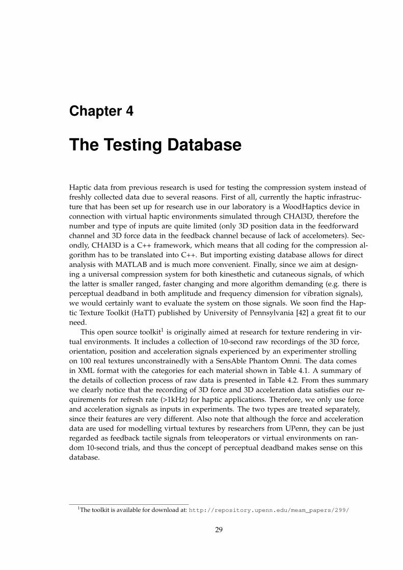
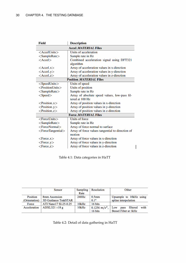
Haptic data from previous research is used for testing the compression system instead offreshly collected data due to several reasons. First of all, currently the haptic infrastruc-ture that has been set up for research use in our laboratory is a WoodHaptics device inconnection with virtual haptic environments simulated through CHAI3D, therefore thenumber and type of inputs are quite limited (only 3D position data in the feedforwardchannel and 3D force data in the feedback channel because of lack of accelometers). Sec-ondly, CHAI3D is a C++ framework, which means that all coding for the compression al-gorithm has to be translated into C++. But importing existing database allows for directanalysis with MATLAB and is much more convenient. Finally, since we aim at design-ing a universal compression system for both kinesthetic and cutaneous signals, of whichthe latter is smaller ranged, faster changing and more algorithm demanding (e.g. there isperceptual deadband in both amplitude and frequency dimension for vibration signals),we would certainly want to evaluate the system on those signals. We soon find the Hap-tic Texture Toolkit (HaTT) published by University of Pennsylvania [42] a great fit to ourneed.
This open source toolkit1 is originally aimed at research for texture rendering in vir-tual environments. It includes a collection of 10-second raw recordings of the 3D force,orientation, position and acceleration signals experienced by an experimenter strollingon 100 real textures unconstrainedly with a SensAble Phantom Omni. The data comesin XML format with the categories for each material shown in Table 4.1. A summary ofthe details of collection process of raw data is presented in Table 4.2. From thes summarywe clearly notice that the recording of 3D force and 3D acceleration data satisfies our re-quirements for refresh rate (>1kHz) for haptic applications. Therefore, we only use forceand acceleration signals as inputs in experiments. The two types are treated separately,since their features are very different. Also note that although the force and accelerationdata are used for modelling virtual textures by researchers from UPenn, they can be justregarded as feedback tactile signals from teleoperators or virtual environments on ran-dom 10-second trials, and thus the concept of perceptual deadband makes sense on thisdatabase.
1The toolkit is available for download at: http://repository.upenn.edu/meam_papers/299/
29
30 CHAPTER 4. THE TESTING DATABASE
Table 4.1: Data categories in HaTT
Table 4.2: Detail of data gathering in HaTT
Chapter 5
Experiments and Results
5.1 Data Pre-processing and Analysis
As a first step, 3D force and 3D acceleration data from UPenn 100-material texture databaseare extracted from corresponding labels in XML files mentioned in Table 4.1, downsam-pled to 1kHz (so 10000 instead of 100000 samples for each recording), and stored in .MATstructures suitable for MATLAB processing. After that, the two types of data will each gothrough the same compression system. The 3D force signals from 100-materials are re-garded as parallel input channels in this study, simulating inputs from multiple sensorsin a haptic system. Hence we are able to choose from 1-300 input channels. The 3D ac-celeration data is treated the same way. Although inputs from different textures may notresemble the behavior of multi-input on a single haptic device, it does no harm to thisstudy, since exploring correlations between inputs is out of scope of this thesis.
Plotting the force data range of 100 materials gives Figure 5.1. Obviously, the x and y
direction force data are almost symmetrical around zero value for each material, whereasthe z direction data only span negative value. It implies that for the codebook trainingmethod, it is unnecessary to use codebooks with an extra sign bit for z direction forcesignal. The acceleration data range plots are shown in Figure .For acceleration signals,all three directions tend to have symmetric distribution around zero value, but the sig-nal range for different materials vary drastically. This means we should better train thecodebook on individual channels in order to achieve good performance.
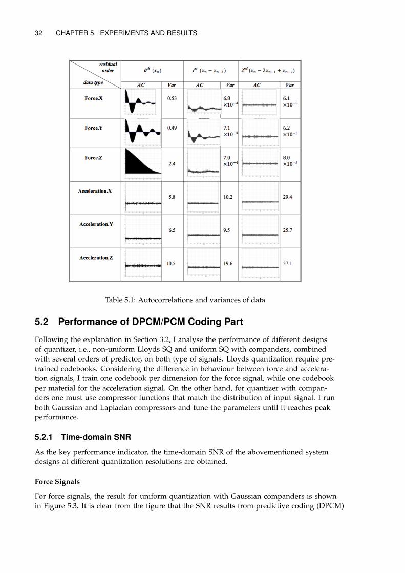
Other properties including variance and autocorrelation patterns up to 2000 sam-ples (2 seconds) of the signals as well as of their residuals of different orders are pre-sented in Table 5.1. The plots of autocorrelation functions give us general impressionabout how much neighboring samples are correlated in each type of input. Apparently, ahuge decorrelation takes place when we move from direct signal amplitude to first orderdifference for the force signal, and the variance also drops immensely. As for accelera-tion signals, however, the signal amplitude is barely correlated itself and the variance in-creases as we increase the order of difference. This indicates that we should better oper-ate on first order difference signals of force and amplitude signal of acceleration, in orderto utilize sample-wise signal correlation in the channel shuffling part, while minimizingthe range of their values.
31
32 CHAPTER 5. EXPERIMENTS AND RESULTS
Table 5.1: Autocorrelations and variances of data
5.2 Performance of DPCM/PCM Coding Part
Following the explanation in Section 3.2, I analyse the performance of different designsof quantizer, i.e., non-uniform Lloyds SQ and uniform SQ with companders, combinedwith several orders of predictor, on both type of signals. Lloyds quantization require pre-trained codebooks. Considering the difference in behaviour between force and accelera-tion signals, I train one codebook per dimension for the force signal, while one codebookper material for the acceleration signal. On the other hand, for quantizer with compan-ders one must use compressor functions that match the distribution of input signal. I runboth Gaussian and Laplacian compressors and tune the parameters until it reaches peakperformance.
5.2.1 Time-domain SNR
As the key performance indicator, the time-domain SNR of the abovementioned systemdesigns at different quantization resolutions are obtained.
Force Signals
For force signals, the result for uniform quantization with Gaussian companders is shownin Figure 5.3. It is clear from the figure that the SNR results from predictive coding (DPCM)
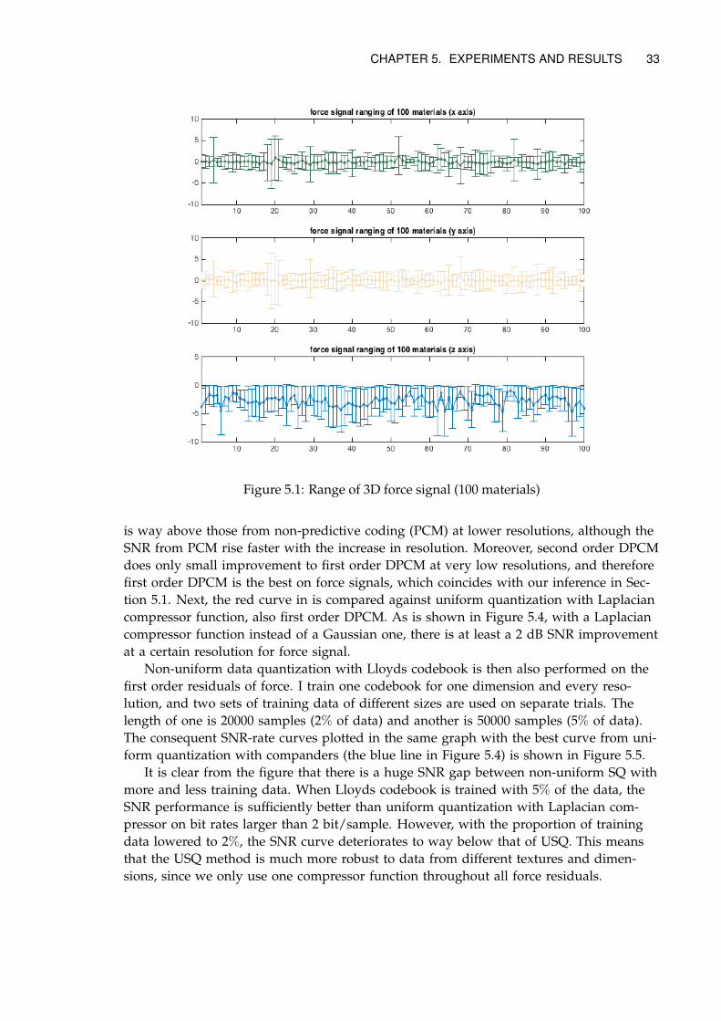
CHAPTER 5. EXPERIMENTS AND RESULTS 33
Figure 5.1: Range of 3D force signal (100 materials)
is way above those from non-predictive coding (PCM) at lower resolutions, although theSNR from PCM rise faster with the increase in resolution. Moreover, second order DPCMdoes only small improvement to first order DPCM at very low resolutions, and thereforefirst order DPCM is the best on force signals, which coincides with our inference in Sec-tion 5.1. Next, the red curve in is compared against uniform quantization with Laplaciancompressor function, also first order DPCM. As is shown in Figure 5.4, with a Laplaciancompressor function instead of a Gaussian one, there is at least a 2 dB SNR improvementat a certain resolution for force signal.
Non-uniform data quantization with Lloyds codebook is then also performed on thefirst order residuals of force. I train one codebook for one dimension and every reso-lution, and two sets of training data of different sizes are used on separate trials. Thelength of one is 20000 samples (2% of data) and another is 50000 samples (5% of data).The consequent SNR-rate curves plotted in the same graph with the best curve from uni-form quantization with companders (the blue line in Figure 5.4) is shown in Figure 5.5.
It is clear from the figure that there is a huge SNR gap between non-uniform SQ withmore and less training data. When Lloyds codebook is trained with 5% of the data, theSNR performance is sufficiently better than uniform quantization with Laplacian com-pressor on bit rates larger than 2 bit/sample. However, with the proportion of trainingdata lowered to 2%, the SNR curve deteriorates to way below that of USQ. This meansthat the USQ method is much more robust to data from different textures and dimen-sions, since we only use one compressor function throughout all force residuals.
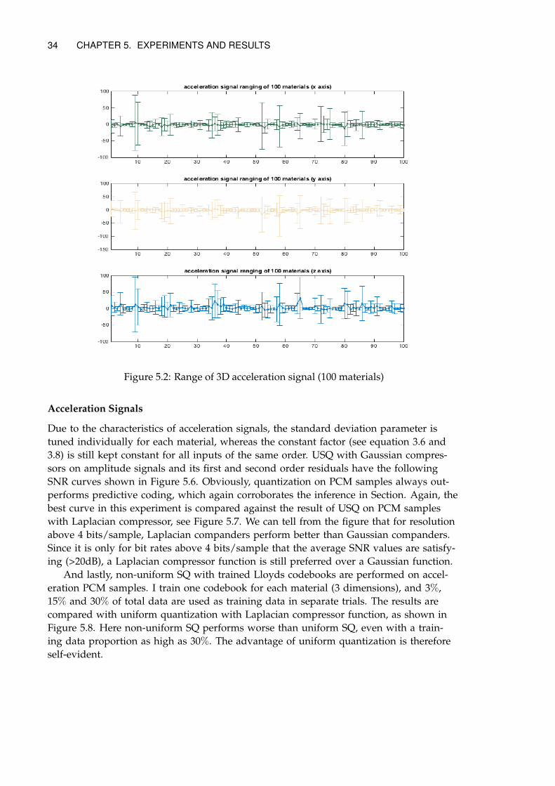
34 CHAPTER 5. EXPERIMENTS AND RESULTS
Figure 5.2: Range of 3D acceleration signal (100 materials)
Acceleration Signals
Due to the characteristics of acceleration signals, the standard deviation parameter istuned individually for each material, whereas the constant factor (see equation 3.6 and3.8) is still kept constant for all inputs of the same order. USQ with Gaussian compres-sors on amplitude signals and its first and second order residuals have the followingSNR curves shown in Figure 5.6. Obviously, quantization on PCM samples always out-performs predictive coding, which again corroborates the inference in Section. Again, thebest curve in this experiment is compared against the result of USQ on PCM sampleswith Laplacian compressor, see Figure 5.7. We can tell from the figure that for resolutionabove 4 bits/sample, Laplacian companders perform better than Gaussian companders.Since it is only for bit rates above 4 bits/sample that the average SNR values are satisfy-ing (>20dB), a Laplacian compressor function is still preferred over a Gaussian function.
And lastly, non-uniform SQ with trained Lloyds codebooks are performed on accel-eration PCM samples. I train one codebook for each material (3 dimensions), and 3%,15% and 30% of total data are used as training data in separate trials. The results arecompared with uniform quantization with Laplacian compressor function, as shown inFigure 5.8. Here non-uniform SQ performs worse than uniform SQ, even with a train-ing data proportion as high as 30%. The advantage of uniform quantization is thereforeself-evident.
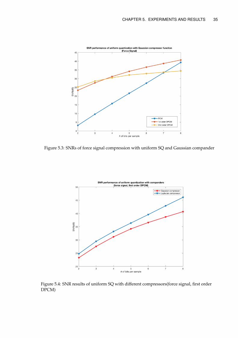
CHAPTER 5. EXPERIMENTS AND RESULTS 35
Figure 5.3: SNRs of force signal compression with uniform SQ and Gaussian compander
Figure 5.4: SNR results of uniform SQ with different compressors(force signal, first orderDPCM)
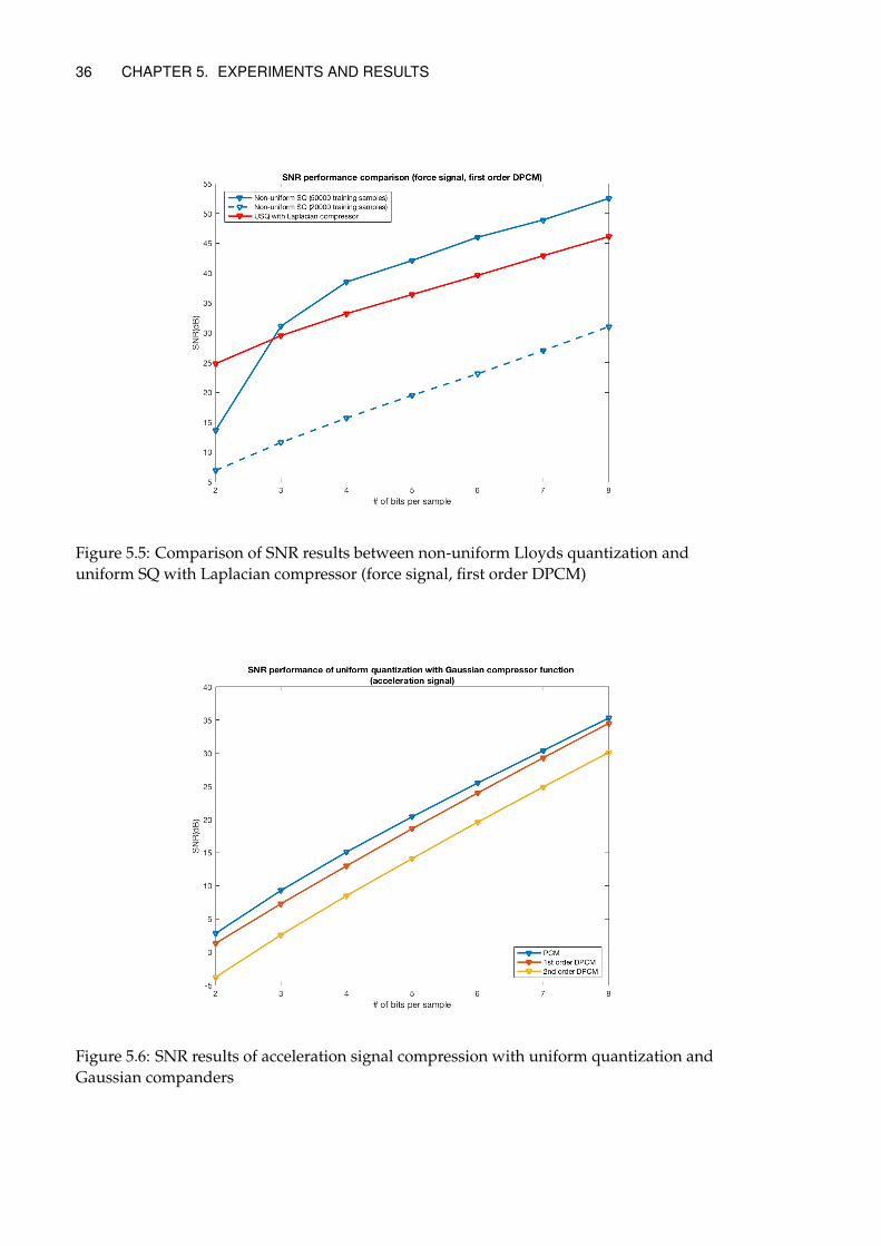
36 CHAPTER 5. EXPERIMENTS AND RESULTS
Figure 5.5: Comparison of SNR results between non-uniform Lloyds quantization anduniform SQ with Laplacian compressor (force signal, first order DPCM)
Figure 5.6: SNR results of acceleration signal compression with uniform quantization andGaussian companders
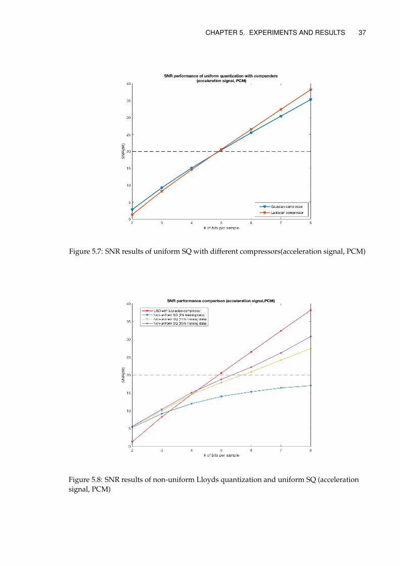
CHAPTER 5. EXPERIMENTS AND RESULTS 37
Figure 5.7: SNR results of uniform SQ with different compressors(acceleration signal, PCM)
Figure 5.8: SNR results of non-uniform Lloyds quantization and uniform SQ (accelerationsignal, PCM)
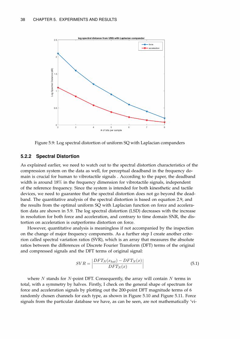
38 CHAPTER 5. EXPERIMENTS AND RESULTS
Figure 5.9: Log spectral distortion of uniform SQ with Laplacian companders
5.2.2 Spectral Distortion
As explained earlier, we need to watch out to the spectral distortion characteristics of thecompression system on the data as well, for perceptual deadband in the frequency do-main is crucial for human to vibrotactile signals . According to the paper, the deadbandwidth is around 18% in the frequency dimension for vibrotactile signals, independentof the reference frequency. Since the system is intended for both kinesthetic and tactiledevices, we need to guarantee that the spectral distortion does not go beyond the dead-band. The quantitative analysis of the spectral distortion is based on equation 2.9, andthe results from the optimal uniform SQ with Laplacian function on force and accelera-tion data are shown in 5.9. The log spectral distortion (LSD) decreases with the increasein resolution for both force and acceleration, and contrary to time domain SNR, the dis-tortion on acceleration is outperforms distortion on force.
However, quantitative analysis is meaningless if not accompanied by the inspectionon the change of major frequency components. As a further step I create another crite-rion called spectral variation ratios (SVR), which is an array that measures the absoluteratios between the differences of Discrete Fourier Transform (DFT) terms of the originaland compressed signals and the DFT terms of original signal:
SV R =
∣∣∣∣DFTN (xhat)−DFTN (x)
DFTN (x)
∣∣∣∣ (5.1)
where N stands for N -point DFT. Consequently, the array will contain N terms intotal, with a symmetry by halves. Firstly, I check on the general shape of spectrum forforce and acceleration signals by plotting out the 200-point DFT magnitude terms of 6randomly chosen channels for each type, as shown in Figure 5.10 and Figure 5.11. Forcesignals from the particular database we have, as can be seen, are not mathematically ‘vi-
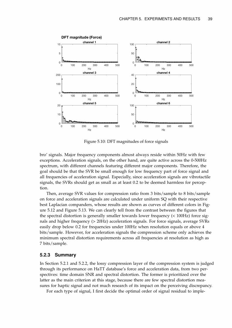
CHAPTER 5. EXPERIMENTS AND RESULTS 39
Figure 5.10: DFT magnitudes of force signals
bro’ signals. Major frequency components almost always reside within 50Hz with fewexceptions. Acceleration signals, on the other hand, are quite active across the 0-500Hzspectrum, with different channels featuring different major components. Therefore, thegoal should be that the SVR be small enough for low frequency part of force signal andall frequencies of acceleration signal. Especially, since acceleration signals are vibrotactilesignals, the SVRs should get as small as at least 0.2 to be deemed harmless for percep-tion.
Then, average SVR values for compression ratio from 3 bits/sample to 8 bits/sampleon force and acceleration signals are calculated under uniform SQ with their respectivebest Laplacian companders, whose results are shown as curves of different colors in Fig-ure 5.12 and Figure 5.13. We can clearly tell from the contrast between the figures thatthe spectral distortion is generally smaller towards lower frequency (< 100Hz) force sig-nals and higher frequency (> 20Hz) acceleration signals. For force signals, average SVRseasily drop below 0.2 for frequencies under 100Hz when resolution equals or above 4bits/sample. However, for acceleration signals the compression scheme only achieves theminimum spectral distortion requirements across all frequencies at resolution as high as7 bits/sample.
5.2.3 Summary
In Section 5.2.1 and 5.2.2, the lossy compression layer of the compression system is judgedthrough its performance on HaTT database’s force and acceleration data, from two per-spectives: time domain SNR and spectral distortion. The former is prioritized over thelatter as the main criterion at this stage, because there are few spectral distortion mea-sures for haptic signal and not much research of its impact on the perceiving discrepancy.
For each type of signal, I first decide the optimal order of signal residual to imple-
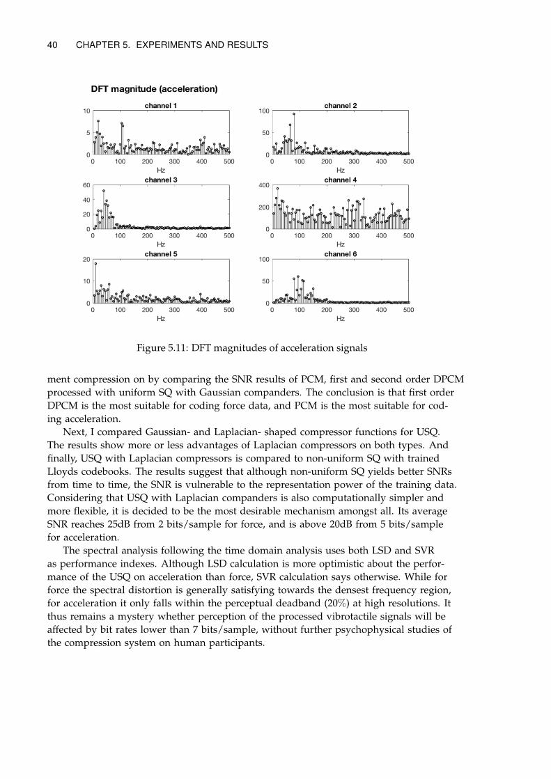
40 CHAPTER 5. EXPERIMENTS AND RESULTS
Figure 5.11: DFT magnitudes of acceleration signals
ment compression on by comparing the SNR results of PCM, first and second order DPCMprocessed with uniform SQ with Gaussian companders. The conclusion is that first orderDPCM is the most suitable for coding force data, and PCM is the most suitable for cod-ing acceleration.
Next, I compared Gaussian- and Laplacian- shaped compressor functions for USQ.The results show more or less advantages of Laplacian compressors on both types. Andfinally, USQ with Laplacian compressors is compared to non-uniform SQ with trainedLloyds codebooks. The results suggest that although non-uniform SQ yields better SNRsfrom time to time, the SNR is vulnerable to the representation power of the training data.Considering that USQ with Laplacian companders is also computationally simpler andmore flexible, it is decided to be the most desirable mechanism amongst all. Its averageSNR reaches 25dB from 2 bits/sample for force, and is above 20dB from 5 bits/samplefor acceleration.
The spectral analysis following the time domain analysis uses both LSD and SVRas performance indexes. Although LSD calculation is more optimistic about the perfor-mance of the USQ on acceleration than force, SVR calculation says otherwise. While forforce the spectral distortion is generally satisfying towards the densest frequency region,for acceleration it only falls within the perceptual deadband (20%) at high resolutions. Itthus remains a mystery whether perception of the processed vibrotactile signals will beaffected by bit rates lower than 7 bits/sample, without further psychophysical studies ofthe compression system on human participants.
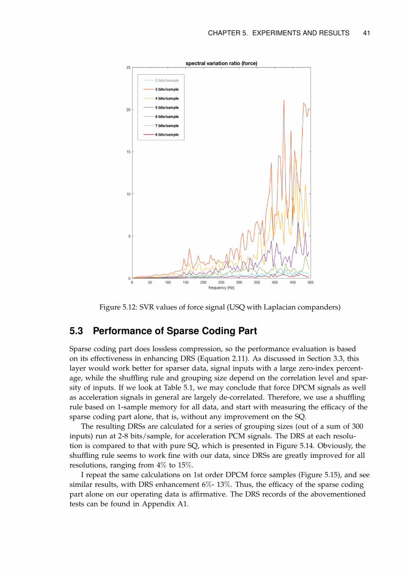
CHAPTER 5. EXPERIMENTS AND RESULTS 41
Figure 5.12: SVR values of force signal (USQ with Laplacian companders)
5.3 Performance of Sparse Coding Part
Sparse coding part does lossless compression, so the performance evaluation is basedon its effectiveness in enhancing DRS (Equation 2.11). As discussed in Section 3.3, thislayer would work better for sparser data, signal inputs with a large zero-index percent-age, while the shuffling rule and grouping size depend on the correlation level and spar-sity of inputs. If we look at Table 5.1, we may conclude that force DPCM signals as wellas acceleration signals in general are largely de-correlated. Therefore, we use a shufflingrule based on 1-sample memory for all data, and start with measuring the efficacy of thesparse coding part alone, that is, without any improvement on the SQ.
The resulting DRSs are calculated for a series of grouping sizes (out of a sum of 300inputs) run at 2-8 bits/sample, for acceleration PCM signals. The DRS at each resolu-tion is compared to that with pure SQ, which is presented in Figure 5.14. Obviously, theshuffling rule seems to work fine with our data, since DRSs are greatly improved for allresolutions, ranging from 4% to 15%.
I repeat the same calculations on 1st order DPCM force samples (Figure 5.15), and seesimilar results, with DRS enhancement 6%- 13%. Thus, the efficacy of the sparse codingpart alone on our operating data is affirmative. The DRS records of the abovementionedtests can be found in Appendix A1.
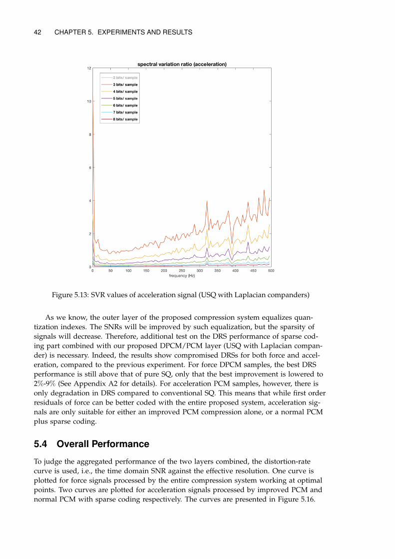
42 CHAPTER 5. EXPERIMENTS AND RESULTS
Figure 5.13: SVR values of acceleration signal (USQ with Laplacian companders)
As we know, the outer layer of the proposed compression system equalizes quan-tization indexes. The SNRs will be improved by such equalization, but the sparsity ofsignals will decrease. Therefore, additional test on the DRS performance of sparse cod-ing part combined with our proposed DPCM/PCM layer (USQ with Laplacian compan-der) is necessary. Indeed, the results show compromised DRSs for both force and accel-eration, compared to the previous experiment. For force DPCM samples, the best DRSperformance is still above that of pure SQ, only that the best improvement is lowered to2%-9% (See Appendix A2 for details). For acceleration PCM samples, however, there isonly degradation in DRS compared to conventional SQ. This means that while first orderresiduals of force can be better coded with the entire proposed system, acceleration sig-nals are only suitable for either an improved PCM compression alone, or a normal PCMplus sparse coding.
5.4 Overall Performance
To judge the aggregated performance of the two layers combined, the distortion-ratecurve is used, i.e., the time domain SNR against the effective resolution. One curve isplotted for force signals processed by the entire compression system working at optimalpoints. Two curves are plotted for acceleration signals processed by improved PCM andnormal PCM with sparse coding respectively. The curves are presented in Figure 5.16.
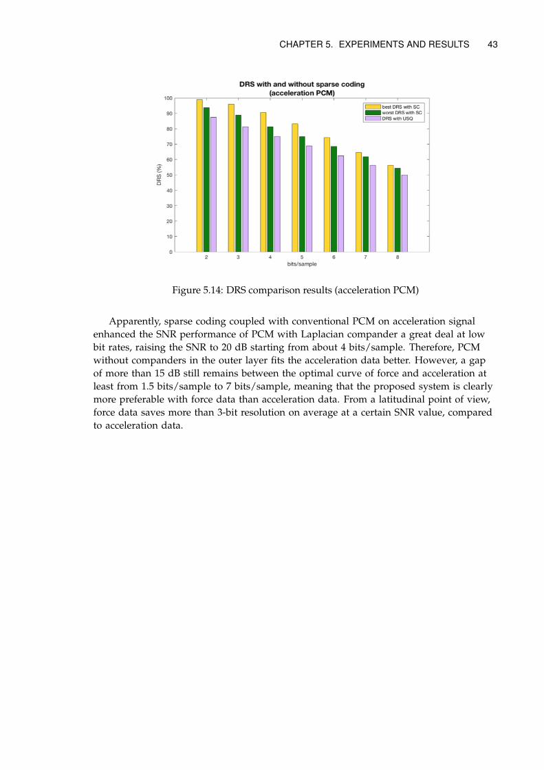
CHAPTER 5. EXPERIMENTS AND RESULTS 43
Figure 5.14: DRS comparison results (acceleration PCM)
Apparently, sparse coding coupled with conventional PCM on acceleration signalenhanced the SNR performance of PCM with Laplacian compander a great deal at lowbit rates, raising the SNR to 20 dB starting from about 4 bits/sample. Therefore, PCMwithout companders in the outer layer fits the acceleration data better. However, a gapof more than 15 dB still remains between the optimal curve of force and acceleration atleast from 1.5 bits/sample to 7 bits/sample, meaning that the proposed system is clearlymore preferable with force data than acceleration data. From a latitudinal point of view,force data saves more than 3-bit resolution on average at a certain SNR value, comparedto acceleration data.
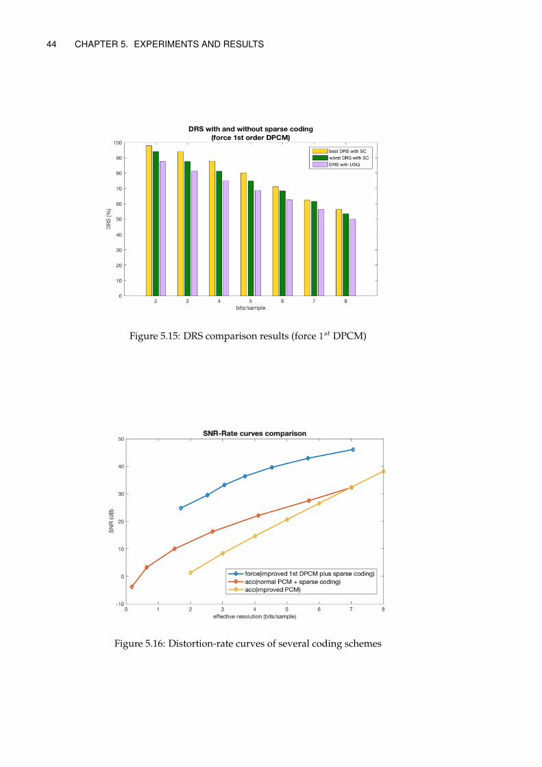
44 CHAPTER 5. EXPERIMENTS AND RESULTS
Figure 5.15: DRS comparison results (force 1st DPCM)
Figure 5.16: Distortion-rate curves of several coding schemes
Chapter 6
Conclusions and Future Work
6.1 Conclusions
A sample-based coding solution for mass input of kinaesthetic and tactile signals thatwill satisfy the strictest latency requirement of haptic applications is proposed and elab-orated in this thesis. The system is implemented in MATLAB and evaluated both in sep-arate modules and as a whole, on a texture tactile database, of which force and accelera-tion data are our focus. The update rate is 1kHz and sample resolution is 16 bits for theuncompressed data. All input channels are transmitted in one packet and we accommo-date up to 300 channels in the experiments. Therefore, the data rate of a single channel is16kbps, the maximum packet size is 600 Bytes and the packet rate of the system is 1000packets/s. Individual samples are compressed to 2b – 8b in all experiments followed.Packet overheads, channel coding, network delay and noise are not included in our dis-cussion. The performance measurements used are SNR, LSD, SVR, DRS and distortion-rate curve as mentioned in Chapter 2 and 4.
Two schemes for modifying the conventional DPCM/PCM, i.e. non-uniform LloydsSQ and uniform SQ with companders, are discussed and compared. Results show thatalthough non-uniform SQ is competitive in terms of SNR, its performance is extremelysensitive to the choice of training set. Uniform SQ with optimal Laplacian compander, onthe other hand, yields good average SNR even with the same parameter shared amongall channels, and is flexible for switching among resolutions. Therefore, uniform SQ withLaplacian compander is the recommended scheme. Its spectral performance is then anal-ysed, mainly for perceptual considerations of vibrotactile signals. The results imply thatperceptual transparency may be harder to achieve on acceleration data with the currentscheme. However, we may only make conclusions after future perceptual studies areconducted.
The lossless layer is judged with DRSs first calculated for lossless layer combinedwith conventional PCM/DPCM, and then for the same lossless layer combined with therecommended lossy layer design, in which the resulting data is less sparse. This resultssuggests that force signal is suitable for the entire proposed compression scheme, whileacceleration signal will be better coded with the lossy layer or the lossless layer alone.
Finally, the distortion-rate curves of several schemes are plotted. It suggests that theacceleration PCM data should best be coded with the proposed lossless layer alone, andforce DPCM data should be compressed with both the lossy and lossless layer.
45
46 CHAPTER 6. CONCLUSIONS AND FUTURE WORK
6.2 Future Work
Haptic coding research is still in its childhood, as has been discussed in details in Sec-tion 1.2. To the best of my knowledge, this thesis is a pioneer work in proposing andanalysing a real-time haptic coding design aimed to cover both kinaesthetic and tactiledevices, and optimized for multiple channels. There are still many underexplored aspectsand deficiencies in experimental setup. I hereby list some insights for future work on thistopic.
First of all, more databases and online data should be employed in the study of theproposed system. In this thesis study, the whole design of the system is implementedonly in MATLAB, which certainly contains idealism in modelling the reality, neglect-ing some key factors that would influence compression performance. We use only onedatabase for testing, but as far as we know, [43] offers similar surface tactile databasecontaining tool-mediated acceleration and friction recordings of 43 textures. If more ofsuch databases can be included, the conclusions made about this system in this thesiscan be more convincingly validated. Of course, the optimal solution is implementing thesystem with executable codes in real haptic systems, and gather fresh online data. It willallow us to learn more about the arriving patterns, distributions and features of data inreal haptic applications, and the study of parameter tuning such as the constant in com-pressor function and group size in sparse coding will make sense.
Secondly, perceptual analysis of the compression system based on online experimentswith human is not performed in this thesis, and PD approach is not explicitly incorpo-rated into the design, although we leave space for plug-ins of JNDs. We take advan-tage of data sparsity in the proposed scheme, and by sparsity we mean the percentageof zero index in one transmission. Why should groups with zero indexes be omitted dur-ing transmission? It is because they barely contain any information, since we know theyare all zeros once we see the flags. It is the same as the PD. We know the samples withinthe PD contains superfluous information for human perception and can be reconstructedwithout knowing their values. Therefore, in future studies we can set the indexes of sam-ples within deadbands to zero, which is particularly convenient for the DPCM case. Thenwe can evaluate its efficacy on human. But all these can only happen when we have ac-cess to online data.
Thirdly, parameter tuning is not the focus of this study and thus all relevant parame-ters are tuned manually for the optimal points throughout the experiments. In the future,when more haptic data are readily available to us, we can conclude more on the relationbetween data and parameters and search for ways for intelligent parameter tuning.
All in all, I consider real-time haptic coding for mass input and various signal types apromising topic in the coming 5G era. I heartily wish more fruits to be harvested in thisfield in the coming years.
Bibliography
[1] Jeffrey G Andrews, Stefano Buzzi, Wan Choi, Stephen V Hanly, Angel Lozano, An-thony CK Soong, and Jianzhong Charlie Zhang. What will 5g be? IEEE Journal onSelected Areas in Communications, 32(6):1065–1082, 2014.
[2] Adnan Aijaz, Mischa Dohler, A Hamid Aghvami, Vasilis Friderikos, and MagnusFrodigh. Realizing the tactile internet: Haptic communications over next generation5g cellular networks. arXiv preprint arXiv:1510.02826, 2015.
[3] Martin Kuschel, Philipp Kremer, and Martin Buss. Passive haptic data-compressionmethods with perceptual coding for bilateral presence systems. IEEE Transactions onSystems, Man, and Cybernetics-Part A: Systems and Humans, 39(6):1142–1151, 2009.
[4] Sandra Hirche, Peter Hinterseer, Eckehard Steinbach, and Martin Buss. Transparentdata reduction in networked telepresence and teleaction systems. part i: Commu-nication without time delay. Presence: Teleoperators and Virtual Environments, 16(5):523–531, 2007.
[5] Thomas H Massie and J Kenneth Salisbury. The phantom haptic interface: A de-vice for probing virtual objects. In Proceedings of the ASME winter annual meeting, sym-posium on haptic interfaces for virtual environment and teleoperator systems, volume 55,pages 295–300. Chicago, IL, 1994.
[6] Mel Slater and Sylvia Wilbur. A framework for immersive virtual environments(five): Speculations on the role of presence in virtual environments. Presence: Teleop-erators and virtual environments, 6(6):603–616, 1997.
[7] Thomas B Sheridan. Musings on telepresence and virtual presence. Presence: Teleop-erators & Virtual Environments, 1(1):120–126, 1992.
[8] Hong Z Tan, Mandayam A Srinivasan, Brian Eberman, and Belinda Cheng. Humanfactors for the design of force-reflecting haptic interfaces. Dynamic Systems and Con-trol, 55(1):353–359, 1994.
[9] Cyrus Shahabi, Antonio Ortega, and Mohammad R Kolahdouzan. A comparison ofdifferent haptic compression techniques. In Multimedia and Expo, 2002. ICME’02. Pro-ceedings. 2002 IEEE International Conference on, volume 1, pages 657–660. IEEE, 2002.
[10] A Ortega and Y Liu. Lossy compression of haptic data. Touch in virtual environments:Haptics and the design of interactive systems, pages 119–136, 2002.
47
48 BIBLIOGRAPHY
[11] Christoph W Borst. Predictive coding for efficient host-device communication in apneumatic force-feedback display. In First Joint Eurohaptics Conference and Symposiumon Haptic Interfaces for Virtual Environment and Teleoperator Systems. World Haptics Con-ference, pages 596–599. IEEE, 2005.
[12] Shogo Okamoto and Yoji Yamada. Perceptual properties of vibrotactile material tex-ture: Effects of amplitude changes and stimuli beneath detection thresholds. In Sys-tem Integration (SII), 2010 IEEE/SICE International Symposium on, pages 384–389. IEEE,2010.
[13] Shogo Okamoto and Yoji Yamada. Lossy data compression of vibrotactile material-like textures. IEEE transactions on haptics, 6(1):69–80, 2013.
[14] Rahul Chaudhari, Burak Çizmeci, Katherine J Kuchenbecker, Seungmoon Choi, andEckehard Steinbach. Low bitrate source-filter model based compression of vibrotac-tile texture signals in haptic teleoperation. In Proceedings of the 20th ACM internationalconference on Multimedia, pages 409–418. ACM, 2012.
[15] Hiroyuki Tanaka and Kouhei Ohnishi. Lossy compression of haptic data by usingdct. IEEJ Transactions on Industry Applications, 130(8), 2010.
[16] Tomohiro Nakano, Seiji Uozumi, Rolf Johansson, and Kouhei Ohnishi. A quanti-zation method for haptic data lossy compression. In Mechatronics (ICM), 2015 IEEEInternational Conference on, pages 126–131. IEEE, 2015.
[17] Peter Hinterseer, E Steinbach, Sandra Hirche, and Martin Buss. A novel, psy-chophysically motivated transmission approach for haptic data streams in telepres-ence and teleaction systems. In Proceedings.(ICASSP’05). IEEE International Conferenceon Acoustics, Speech, and Signal Processing, 2005., volume 2, pages ii–1097. IEEE, 2005.
[18] Peter Hinterseer, Sandra Hirche, Subhasis Chaudhuri, Eckehard Steinbach, and Mar-tin Buss. Perception-based data reduction and transmission of haptic data in telep-resence and teleaction systems. IEEE Transactions on Signal Processing, 56(2):588–597,2008.
[19] Michael F Zaeh, Stella Clarke, Peter Hinterseer, and Eckehard Steinbach. Telepres-ence across networks: A combined deadband and prediction approach. In Tenth In-ternational Conference on Information Visualisation (IV’06), pages 597–604. IEEE, 2006.
[20] Iason Vittorias, Julius Kammerl, Sandra Hirche, and Eckehard Steinbach. Percep-tual coding of haptic data in time-delayed teleoperation. In EuroHaptics conference,2009 and Symposium on Haptic Interfaces for Virtual Environment and Teleoperator Systems.World Haptics 2009. Third Joint, pages 208–213. IEEE, 2009.
[21] Loi Huynh and Mehrdad H Zadeh. Effects of haptic data compression on user per-formance in collaborative haptic virtual environment. In Haptic, Audio and VisualEnvironments and Games (HAVE), 2014 IEEE International Symposium on, pages 106–111.IEEE, 2014.
[22] Jae-Young Lee and Shahram Payandeh. Performance evaluation of haptic data com-pression methods in teleoperation systems. In World Haptics Conference (WHC), 2011IEEE, pages 137–142. IEEE, 2011.
BIBLIOGRAPHY 49
[23] Julius Kammerl, Rahul Chaudhari, and Eckehard Steinbach. Combining contactmodels with perceptual data reduction for efficient haptic data communication innetworked ves. IEEE Transactions on Instrumentation and Measurement, 60(1):57–68,2011.
[24] Julius Kammerl, Iason Vittorias, Verena Nitsch, Berthold Faerber, Eckehard Stein-bach, and Sandra Hirche. Perception-based data reduction for haptic force-feedbacksignals using velocity-adaptive deadbands. Presence: Teleoperators and Virtual Environ-ments, 19(5):450–462, 2010.
[25] N Sakr, J Zhou, ND Georganas, J Zhao, and X Shen. Prediction-based haptic datareduction and compression in tele-mentoring systems. In Instrumentation and Mea-surement Technology Conference Proceedings, 2008. IMTC 2008. IEEE, pages 1828–1832.IEEE, 2008.
[26] Rahul Chaudhari, Clemens Schuwerk, Mojtaba Danaei, and Eckehard Steinbach. Per-ceptual and bitrate-scalable coding of haptic surface texture signals. IEEE Journal ofSelected Topics in Signal Processing, 9(3):462–473, 2015.
[27] Asad Tirmizi, Claudio Pacchierotti, Irfan Hussain, Gianluca Alberico, and DomenicoPrattichizzo. A perceptually-motivated deadband compression approach for cuta-neous haptic feedback. In 2016 IEEE Haptics Symposium (HAPTICS), pages 223–228.IEEE, 2016.
[28] Xiao-Dong Pang, Hong Z Tan, and Nathaniel I Durlach. Manual discrimination offorce using active finger motion. Perception & psychophysics, 49(6):531–540, 1991.
[29] Jack M Loomis and Susan J Lederman. Tactual perception. Handbook of perception andhuman performances, 2:2, 1986.
[30] Susan J Lederman and Roberta L Klatzky. Haptic perception: A tutorial. Attention,Perception, & Psychophysics, 71(7):1439–1459, 2009.
[31] Sandra Hirche and Martin Buss. Human-oriented control for haptic teleoperation.Proceedings of the IEEE, 100(3):623–647, 2012.
[32] James C Craig. Difference threshold for intensity of tactile stimuli. Perception & Psy-chophysics, 11(2):150–152, 1972.
[33] Helena Pongrac. Vibrotactile perception: examining the coding of vibrations and thejust noticeable difference under various conditions. Multimedia systems, 13(4):297–307,2008.
[34] Yuan D. Enhancing your device design through tactile feedback.
[35] Jack Tigh Dennerlein, David B Martin, and Christopher Hasser. Force-feedback im-proves performance for steering and combined steering-targeting tasks. In Proceed-ings of the SIGCHI conference on Human Factors in Computing Systems, pages 423–429.ACM, 2000.
50 BIBLIOGRAPHY
[36] Jonas Forsslund, Michael Yip, and Eva-Lotta Sallnäs. Woodenhaptics: A starting kitfor crafting force-reflecting spatial haptic devices. In Proceedings of the Ninth Interna-tional Conference on Tangible, Embedded, and Embodied Interaction, pages 133–140. ACM,2015.
[37] Domenico Prattichizzo, Francesco Chinello, Claudio Pacchierotti, and MonicaMalvezzi. Towards wearability in fingertip haptics: a 3-dof wearable device for cuta-neous force feedback. IEEE Transactions on Haptics, 6(4):506–516, 2013.
[38] Vincent Hayward and M Cruz-Hernandez. Tactile display device using distributedlateral skin stretch. In Proceedings of the haptic interfaces for virtual environment and tele-operator systems symposium, volume 69, pages 1309–1314, 2000.
[39] Samuel B Schorr, Zhan Fan Quek, Robert Y Romano, Ilana Nisky, William RProvancher, and Allison M Okamura. Sensory substitution via cutaneous skinstretch feedback. In Robotics and Automation (ICRA), 2013 IEEE International Conferenceon, pages 2341–2346. IEEE, 2013.
[40] Laura Winfield, John Glassmire, J Edward Colgate, and Michael Peshkin. T-pad:Tactile pattern display through variable friction reduction. In Second Joint EuroHapticsConference and Symposium on Haptic Interfaces for Virtual Environment and TeleoperatorSystems (WHC’07), pages 421–426. IEEE, 2007.
[41] Peter Vary and Rainer Martin. Digital speech transmission: Enhancement, coding anderror concealment. John Wiley & Sons, 2006.
[42] Heather Culbertson, Juan Jose Lopez Delgado, and Katherine J Kuchenbecker. Thepenn haptic texture toolkit for modeling, rendering, and evaluating haptic virtualtextures. 2014.
[43] Matti Strese, Jun-Yong Lee, Clemens Schuwerk, Qingfu Han, Hyoung-Gook Kim,and Eckehard Steinbach. A haptic texture database for tool-mediated texture recog-nition and classification. In Haptic, Audio and Visual Environments and Games (HAVE),2014 IEEE International Symposium on, pages 118–123. IEEE, 2014.
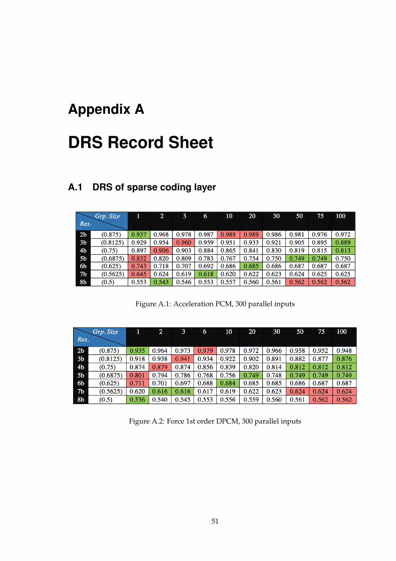
Appendix A
DRS Record Sheet
A.1 DRS of sparse coding layer
Figure A.1: Acceleration PCM, 300 parallel inputs
Figure A.2: Force 1st order DPCM, 300 parallel inputs
51
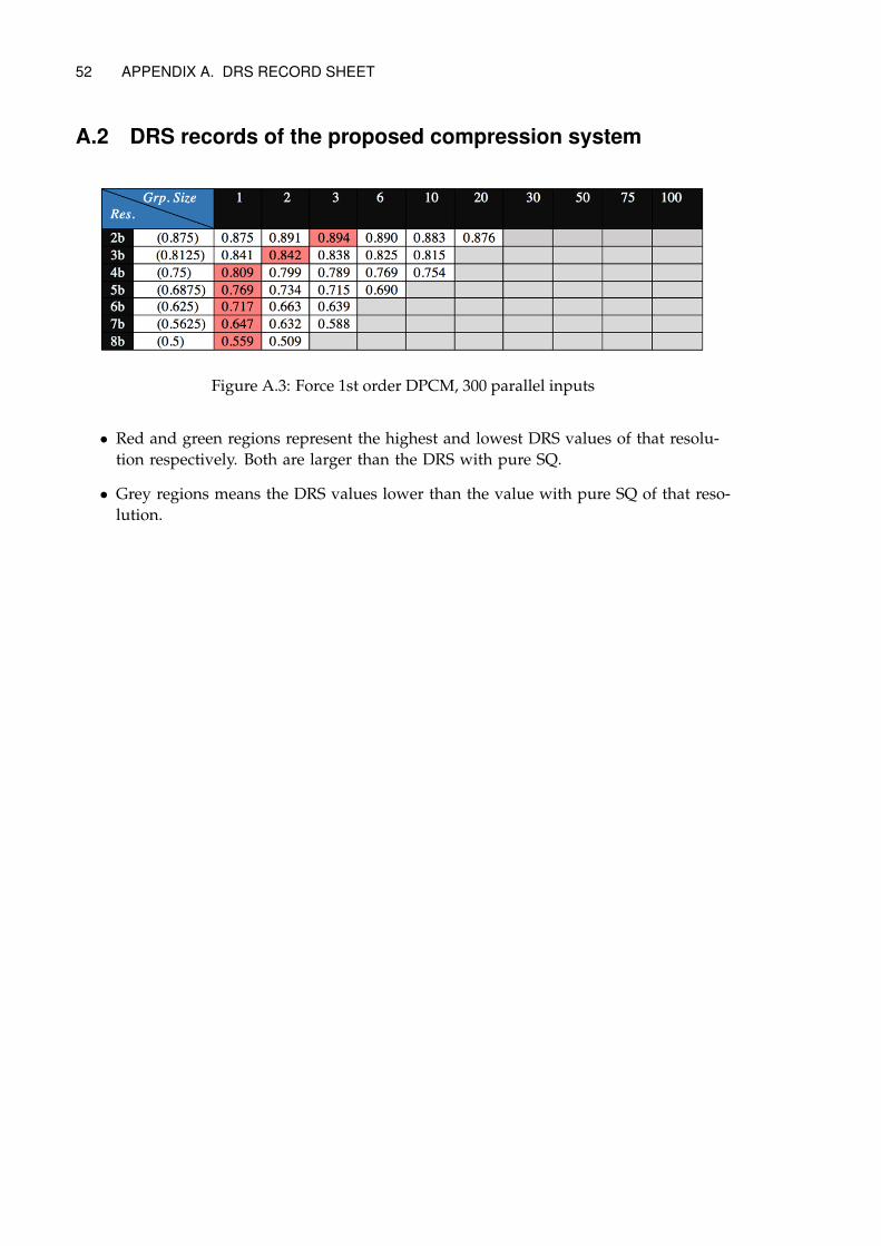
52 APPENDIX A. DRS RECORD SHEET
A.2 DRS records of the proposed compression system
Figure A.3: Force 1st order DPCM, 300 parallel inputs
• Red and green regions represent the highest and lowest DRS values of that resolu-tion respectively. Both are larger than the DRS with pure SQ.
• Grey regions means the DRS values lower than the value with pure SQ of that reso-lution.

TRITA EE 2016:175
www.kth.se