real-time control of industrial urea evaporation … 2 of 8. citation: fahmy im, nassar af,...
TRANSCRIPT
Volume 6 • Issue 2 • 1000227J Chem Eng Process Technol ISSN: 2157-7048 JCEPT, an open access journal
Research Article Open Access
Fahmy et al., J Chem Eng Process Technol 2015, 6:2 DOI: 10.4172/2157-7048.1000227
Research Article Open Access
Real-Time Control of Industrial Urea Evaporation Process Using Model Predictive ControlFahmy IM1*, Nassar AF2, El-Metwally K1 and Kamel AM1
1Department of Electric Power and Machines Engineering, Cairo University, Cairo, Egypt2Chemical Engineering Department, Al Imam Muhammad Ibn Saud Islamic University (IMSIU), Riyadh, KSA
*Corresponding author: Fahmy IM, Department of Electric Power and MachinesEngineering, Cairo University, Cairo, Egypt, Tel: 202 01022044026; E-mail:[email protected]
Received May 04, 2015; Accepted May 23, 2015; Published May 31, 2015
Citation: Fahmy IM, Nassar AF, El-Metwally K, Kamel AM (2015) Real-Time Control of Industrial Urea Evaporation Process Using Model Predictive Control. J Chem Eng Process Technol 6: 227. doi:10.4172/2157-7048.1000227
Copyright: © 2015 Fahmy IM, et al. This is an open-access article distributed under the terms of the Creative Commons Attribution License, which permits unrestricted use, distribution, and reproduction in any medium, provided the original author and source are credited.
AbstractThe evaporation stage in urea industry is a chemical process characterized by natural existence of non-
linear, time delay and multivariable interactions. The traditional control of such process is a great challenge. For this purpose, the advanced process control has been widely used to provide the best practical control strategy for optimum process operation. In this paper the application of model predictive control technique based real-time control system is implemented on a dynamic model of urea evaporation process. The results obtained showed a significant improvement of the control performance in both set-point tracking and disturbance rejection compared to PI control strategy.
Keywords: Urea evaporation modeling; System identification;Model predictive control
IntroductionIn urea industry, the evaporation process is used to increase the
concentration of urea/water solution by vaporizing the water under certain conditions of vacuum and temperature, these conditions are essential to avoid urea crystallization and any undesired substance formulation. The main control problem appears during the plant load change, accordingly urea/water solution product concentration will be disturbed until the vacuum and temperature are stabilized, and therefore applying advanced process control (APC) technique is required to improve the control performance for safe and optimum process operation. Model predictive control (MPC) is proved to be the most efficient APC technique, and has been widely applied in industrial fields especially in power, chemical and refining plants, due to its efficiency in handling the constraints in a multivariable process [1]. PC calculations require an accurate empirical model of the process to predict the future plant outputs (controlled variables or CVs). Based on the future outputs, current measurements and reference trajectory, the best trajectory of future control actions manipulated variables or MVs) can be calculated by an optimization function that satisfies the process constraints. A survey and overview of industrial MPC technology are given in [1].
The efficient system identification of a linear model that describes the process dynamics is an important phase in MPC applications. An identification test is required in order to obtain the measured data maximally informative about the process dynamics, which ensures a successful identification. The advantages of using automatic multivariable and closed-loop test are reducing the process disturbance which keeps the CVs within their operational limits, easier to carry out and better model for control. A summary of important issues in MPC identification is discussed in [2].
The simulation of applying MPC based on linear model identification in a real-time industrial framework has become a popular topic for academic research helping to decrease the gap between theory and practical. For example in [3], a research project presents the benefits of applying MPC techniques to the synthesis section of urea plants. The plant model was implemented in a software package called process studio, and interconnected with an industrial MPC controller. In [4], the results of identification and control using
MPC on two chemical processes are presented; the processes were modeled using HYSYS software and connected with MATLAB to run MPC algorithm in a real-time manner. Furthermore, the modeling, dynamic simulation and MPC application of an integrated gasification combined cycle (IGCC) power plant are demonstrated in [5]. The plant was modeled in Aspen Plus/Dynamics and connected to MATLAB/Simulink for real-time MPC implementation.
In this paper, a dynamic modeling and simulation of the industrial urea evaporation process was developed using MATLAB/Simulink as a pilot plant and was controlled by PI control strategy in real-time industrial distributed control system (DCS), the empirical model of the process was obtained from using multivariable closed-loop identification test, and the MPC controller was implemented using MATLAB/Simulink and communicated with the DCS via the OPC (OLE for process control) technology. At last, the results of both PI and MPC strategies are presented.
The evaporation pilot plant
The evaporation process description: The evaporation process uses a long tube vertical evaporator consisting of a heat exchanger (E-1) and a separator (S-1) as shown in Figure 1. The urea/water solution (UWS) feed is pumped into the evaporator with 80% urea concentration and a temperature of about 99°C. The solution passes inside the tubes of the heat exchanger, in which heat is exchanged with low pressure saturated (LPS) steam, causing an increase in the temperature of the mixture (water/urea). In the separator, the UWS and vapor are separated from each other under vacuum pressure, UWS discharges from the bottom of the separator with a concentration about 95%, while the vapor leaves from the top to the condenser. The vacuum is obtained by the application of steam ejector/condenser system.
Journal of Chemical Engineering & Process TechnologyJournal
of C
hem
ical E
ngineering & Process Technology
ISSN: 2157-7048

Page 2 of 8
Citation: Fahmy IM, Nassar AF, El-Metwally K, Kamel AM (2015) Real-Time Control of Industrial Urea Evaporation Process Using Model Predictive Control. J Chem Eng Process Technol 6: 227. doi:10.4172/2157-7048.1000227
Volume 6 • Issue 2 • 1000227J Chem Eng Process Technol ISSN: 2157-7048 JCEPT, an open access journal
2.48 m3), the energies of UWS feed ( uwsfQ ) and product ( uwspQ ) [ Kw ] are defined by
230.0001129 2.261 06
3 0.1089s 2 0.005908 3.688 05sG
s s e∧ ∧
− − −=
+ + + − (5)
Where uwsm is the mass flow rate, x denotes to the feed or product.
The supplied steam energy ( ) [ ]sQ kw and the outlet vapor energy ( )vQ were defined by the product of the steam mass flow
rate kgs
and enthalpy kfkg
. The saturated steam table was
modeled using curve fitting method to calculate the enthalpy at its corresponding pressure (Ps) [bar g] for the supplied steam, while the rising vapor in the separator is considered a superheated steam, which is governed by the superheated steam table.
The mass flow rates of UWS product ( )uwspm and the separated vapor ( )vim were obtained from the material balance of the system, given by
ufuwsp uwsf
up
Cm m
C= (6)
vi uwsf uwspm m m= − (7)
The vacuum pressure (Pv) [bar a] inside the separator was derived according to the ideal gas law, and expressed by the following differential equation
( ) ( ) 5273 * **10 ,p vi vov w
T m mdp M VsKdt k R
−+ −
= = (8)
Where ,vi vom m are the mass flow rates kgs
that pass into and from the
separator, Vs is the separator volume (equals to 2.48 m3), R is the universal gas
constant (equals to 8314 pa
kmol ) and the molecular weight of water (Mw)
is 18.016 gmol
.
According to urea/water phase equilibrium relation, the vapor pressure will rises with temperature of urea/water mixture, therefore the concentration of the lighter component in the liquid phase (water) will decrease, and an approximated mathematical representation of this relation was given by the sets of the following equations [8]:
3186.4416.2886227.02Tp
wP e
− + = (9)
0.95* *1000.92498*
1.06425pvin
pwwx e
=
(10)
( )*
*
100* 1
w ww
w w w
M xCM x Mu x
= + −
(11)
100up wC C= − (12)
where Pw is the vapor pressure [ ]. , wmm Hg x is the water mole fraction, wC is water concentration [%] of UWS product, Mu is the
molecular weight of urea equals to 60.056 gmol
and the upC is urea product concentration [%].
As shown in Figure 1, the control valves V1, V2 and V3 manipulatethe mass flow rates of UWS feed ( )uwsfm ,supplied steam ( )sm and the vacuum pressure respectively. The three control valves were modeled using first order transfer function with variable gain depending on the
Model development: The dynamic modeling of UWS evaporation process was formulated by applying the material and energy balance of the whole system (heat exchanger [E-1] and separator [S-1]) and the urea/water phase equilibrium relation which represents the core of the process non-linearity. In this paper, the following points are assumed during the model development:
• In the heat exchanger (shell side), the supplied LPS mass flow and the condensation mass flow are equal.
• No traces gases in urea/water mixture.
• Linear relation between the outlet vapor mass flow rate and low pressure steam (V3) valve opening.
The density ( )wsρµ3
kgm
and the specific heat capacity ( )wsCρµ
.kj
kg C of UWS were approximately determined as a function of the solution temperature [ ]C and the urea concentration ( )[ ]%uC according to references [6,7], as expressed in the following equations
( ) ( )2.9 0.57 . 1007uws C tempρµ = − + (1)
( )0.003786 . 1.892362C urea tempρ = + (2)
1100 100
u uuws urea water
C CC Cp Cpρ = + −
(3)
Where waterCp is the specific heat capacity of the water, and assumed to be constant (equals to 4.18
.kj
kg C
).
The UWS product temperature (Tp) [C] was obtained by applying the energy balance of the overall system and was formulated by the following differential equation
( ) ( )**Cp Vuwsp
s uwsf v uwspp
uwsp
Q Q in Q Q outaTdt ρ
−+ += (4)
Where V is the volume of the tubes of the heat exchanger (equals to
Figure 1: The evaporator process control loops diagram.

Page 3 of 8
Citation: Fahmy IM, Nassar AF, El-Metwally K, Kamel AM (2015) Real-Time Control of Industrial Urea Evaporation Process Using Model Predictive Control. J Chem Eng Process Technol 6: 227. doi:10.4172/2157-7048.1000227
Volume 6 • Issue 2 • 1000227J Chem Eng Process Technol ISSN: 2157-7048 JCEPT, an open access journal
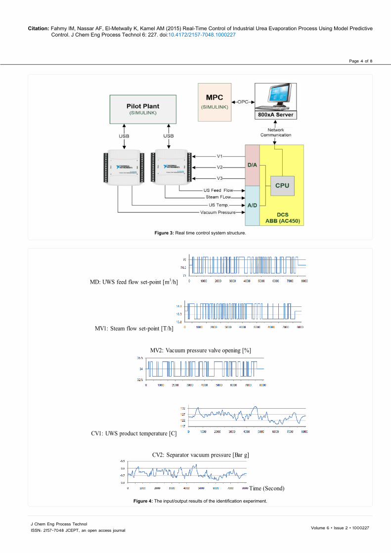
product temperature was disconnected. Second, the vacuum pressure controller (PIC-2) was turned to manual mode. Three different GBN signals were simultaneously generated. First two signals were added to the controller’s set-point FIC-1 and FIC-2 and the third signal was added to V3 output signal. The generated GBN signals settings were chosen as: the sampling time of the generated signals was one second, the mean switch time was 90 second, and the magnitudes was set as follows: ± 1.5 m3/h for UWS feed flow set-point, ± 0.5 T/h for steam flow set-point and ± 1% for vacuum pressure valve opening. The experiment duration time is about 8000 second. The results of this experiment are shown in Figure 4.
System identification techniques: It is recommended to obtain an accurate linear model of the process to remove the mean values of the recorded inputs/outputs data, before applying the identification techniques [9]. The data obtained from the identification test was divided into two parts: The first half was used for identifying the model and the second was used for model validation. The process identification is performed using MATLAB/system identification toolbox [10]. The best validation result was for continuous time transfer function model, this approach uses instrument variable (IV) algorithm for estimating the initialized model parameters, then further refined using nonlinear least square algorithm, for more details about the algorithms see [9,11].
The overall MIMO model is constructed by 6 SISO transfer function models (see Appendix A) describing all inputs and outputs as the following form:
11 12 13
21 22 23
1 . 1 ,22
MDG G GCV MVCV G G G
MV
=
Where ( ) ( ) ( ) ( ) ( )1 ux k Ax k B u k y k Cx k+ = + = (15)
The transfer function model order was configured as (two poles/one zero) for CV1 and (three poles/one zero) for CV2, the total system free coefficients are 30. The validation fit results are 94.65% and 84.46% for CV1 and CV2 respectively. The step responses of the identified transfer functions are shown in Figure 5. The identified model was converted to discrete state space model representation giving the same responses for MPC application.
Model predictive control implementation
In this work, applying MPC technique on the mentioned evaporation process requires modifications in PI control loops that implemented in DCS. According to the identified MIMO
actual valves characteristic.
The evaporator model was implemented using MATLAB
Simulink according to the function structure that shown in Figure 2 which represents the multivariable interactions between the process variables.
Real-time control system: The control objective is to maintain the UWS product temperature at 130°C and the separator vacuum pressure at -0.67 bar g, while UWS feed changes with the plant load. These conditions are imperative to increase the concentration of urea solution from 80% to about 95% while avoiding unsafe operation. The PI control loops scheme of the process is presented in Figure 1, the flow rate of UWS feed which is representing the process load, is controlled by valve (V1) using (FIC-1) controller. In the traditional approach, a cascade controllers (TIC-1) and (FIC-2) are used to maintain the UWS product temperature by manipulating the inlet steam flow via valve (V2). The vacuum pressure in the separator is controlled by valve (V3) using (PIC-1) controller.
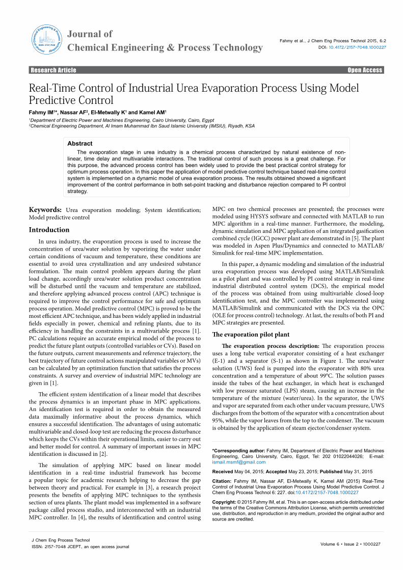
The PI controllers are carried out using real-time industrial DCS controller (ABB-AC450) which is connected with human machine interface (HMI) using 800xA system to operate the pilot plant. Two NI DAQ-6008 devices are used for interfacing between DCS controller and the developed pilot plant model while MPC controller is connected to the system via OPC communication technology. Figure 3 shows the overall hardware structure of the control system.
Multivariable process identification
In this section, we present the multivariable system identification procedure that was performed in this work.
System identification experiment: The objective from the identification experiment is to obtain the measured data maximally informative about the process dynamics. For Multi-Input Multi-Output (MIMO) system, a random binary input signals called test signals are added to the process inputs and the process outputs responses are measured. The test signals parameters are estimated after pretests and gaining experience of the process operation. This ensures process constraints requirements for safe operation during the final test. The Generalized Binary Noise (GBN) test signal was used in this work, which is recommended for industrial processes identification [2].
The experiment is carried out using partial automatic closed-loop method; this was required to perform two modifications in control loops. First, the cascade loop (TIC-1/FIC-2) which controlling the
Figure 2: Evaporator model functions structure.
Page 4 of 8
Citation: Fahmy IM, Nassar AF, El-Metwally K, Kamel AM (2015) Real-Time Control of Industrial Urea Evaporation Process Using Model Predictive Control. J Chem Eng Process Technol 6: 227. doi:10.4172/2157-7048.1000227
Volume 6 • Issue 2 • 1000227J Chem Eng Process Technol ISSN: 2157-7048 JCEPT, an open access journal
Figure 3: Real time control system structure.
MD: UWS feed flow set-point [m3/h]
MV1: Steam flow set-point [T/h]
MV2: Vacuum pressure valve opening [%]
CV1: UWS product temperature [C]
CV2: Separator vacuum pressure [Bar g]
Time (Second)
Figure 4: The input/output results of the identification experiment.

Page 5 of 8
Citation: Fahmy IM, Nassar AF, El-Metwally K, Kamel AM (2015) Real-Time Control of Industrial Urea Evaporation Process Using Model Predictive Control. J Chem Eng Process Technol 6: 227. doi:10.4172/2157-7048.1000227
Volume 6 • Issue 2 • 1000227J Chem Eng Process Technol ISSN: 2157-7048 JCEPT, an open access journal
MD (UWS Flow SP)
MV1(Steam Flow SP)
MV2(Valve 3 opening)
CV1
(Tp
)CV
2(|P
v)
Time (sec.) Time (sec.) Time (sec.)Figure 5: Step responses of the identified MIMOTF [3x2] model.
model, MPC controller interconnected with DCS to manipulate set-point of steam flow controller (FIC-2) and vacuum pressure valve (V3). The CVs of MPC are UWS product temperature (Tp) and the vacuum pressure of the separator (Pv), while set-point of UWS feed flow is considered a measured disturbance (MD). The difference between PI and MPC controller’s strategies is presented in Figure 6.
The MPC controller design is based on a discrete time state-space model of the form:
( ) ( ) ( ) ( ) ( )1 ux k Ax k B u k y k Cx k+ = + = (16)
Where y(k) is the process outputs vector, u(k) is the manipulated variables vector, d(k) is measured disturbance and x(k) is the state variable vector. The main objective of MPC is to calculate the optimal future control action increments ( )U k i∆ + that minimize the predicted deviation E
∧(k+i) between the set-points and the predicted outputs,
subject to process constraints [12].
The quadratic cost function J that reflects the control objective is formulated as
Min ( )
( ) ( ) ( )1
1 0cNp N
i iJ E k i QE k i u k i R U k iτ τ=
= == + + + ∆ + ∆ +∑ ∑ (17)
where Np and Nc are the prediction and control horizons, respectively, Q and are the output and input weight matrices, respectively.
The following parameters were tuned based on trails and errors approach to achieve the best control performance:
- the sample time ts=1s, Np=10, Nc=2;
- Q=[1.4 14], R = [0.05 0.05]
- the manipulated variables constraints are:
5 ≤ steam flow SP ≤ 25 T/h
and 0 ≤ vacuum pressure valve (V3) ≤ 100 %.
The following scenarios were carried out to present the closed-loop responses of the developed evaporation process under the control of MPC vs. PI strategies.
Set-point tracking: In some cases, the UWS product temperature and the separator vacuum pressure set-points shall be modified to satisfy the process requirements. Figures 7 and 8 demonstrate the closed-loop control responses of the process due to changing the set-points of the UWS product temperature from 130 to 126°C and the separator vacuum pressure from -0.67 to -0.57 bar g, respectively.
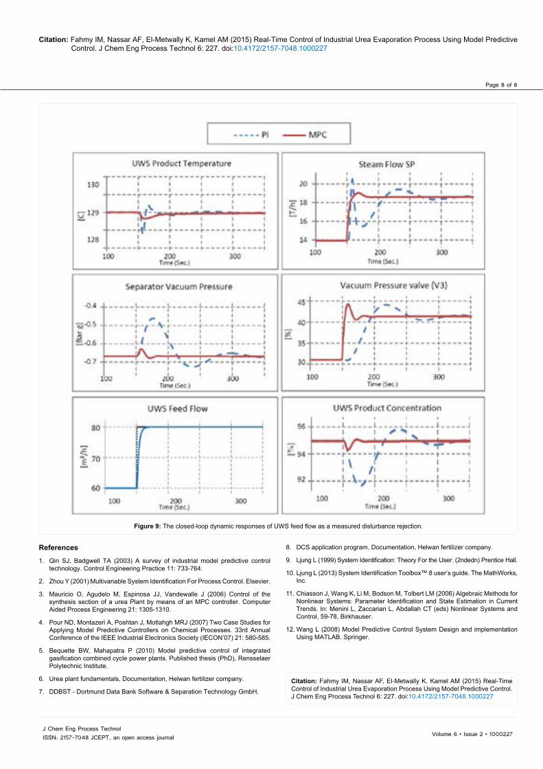
Disturbance rejection: According to the plant load, the productivity of highly concentrated UWS will be affected by modifying the UWS feed flow SP. This will lead to a disturbance in the process variables such as the UWS Product Temperature, the separator vacuum pressure and certainly the UWS product concentration. Figure 9 shows that increasing the UWS Feed flow SP from 60 to 80 m3/h will cause a decrease in the UWS Product Temperature, the separator vacuum pressure and the UWS product concentration. As a result, the control system will increase the supplied steam flow SP and the vacuum pressure valve (V3) opening to maintain the temperature and vacuum pressure close at their set-points. The results from previous scenarios indicate that the performance of MPC strategy is faster and accurate disturbance rejection and set-point tacking than PI control strategy.
ConclusionIn this paper, a dynamic model of an industrial urea evaporation
process has been developed. The water is evaporated from the urea/water solution according to a nonlinear and multivariable relationship between UWS temperature, vapor pressure and urea

Page 6 of 8
Citation: Fahmy IM, Nassar AF, El-Metwally K, Kamel AM (2015) Real-Time Control of Industrial Urea Evaporation Process Using Model Predictive Control. J Chem Eng Process Technol 6: 227. doi:10.4172/2157-7048.1000227
Volume 6 • Issue 2 • 1000227J Chem Eng Process Technol ISSN: 2157-7048 JCEPT, an open access journal
(a) PI control scheme.
(b) MPC control scheme.Figure 6: Comparison between PI and MPC control strategies.
Figure 7: The closed-loop dynamic responses of UWS product temperature set-point tracking.

Page 7 of 8
Citation: Fahmy IM, Nassar AF, El-Metwally K, Kamel AM (2015) Real-Time Control of Industrial Urea Evaporation Process Using Model Predictive Control. J Chem Eng Process Technol 6: 227. doi:10.4172/2157-7048.1000227
Volume 6 • Issue 2 • 1000227J Chem Eng Process Technol ISSN: 2157-7048 JCEPT, an open access journal
product concentration which called urea/water phase equilibrium, this process is considered a challenge in a standard control problem. Traditional PI control and linear model predictive control strategies were applied on the process based on industrial real-time control system.
The results that have been reached reinforce the reliance on using MPC in chemical industries to improve the control performance of processes that often characterized by nonlinear, multivariable interactions and time delay properties compared to PI control strategy. Therefore, this helps to develop the industry in order to reduce energy consumption, optimize the process operation, improve the products quality and finally increase the profitability.
Appendix AThe identified transfer function model:
110.01148 0.001862 0.1363s 0.004441
sGs∧
−=
+ +
120.012 0.005996
2 0.08271s 0.000646sG
s∧− +
=+ +
130.009825 0.0013872 0.06575s 0.000417
sGs∧
+=
+ +
212.979e 05 8.027 09
3 0.06622s 2 0.002681 7.736 07s eG
s s e∧ ∧
− + −=
+ + + −
230.0001129 2.261 06
3 0.1089s 2 0.005908 3.688 05sG
s s e∧ ∧
− − −=
+ + + −
230.0001129 2.261 06
3 0.1089s 2 0.005908 3.688 05sG
s s e∧ ∧
− − −=
+ + + −
Figure 8: The Closed-loop dynamic responses of vacuum pressure set-point tracking.
Page 8 of 8
Citation: Fahmy IM, Nassar AF, El-Metwally K, Kamel AM (2015) Real-Time Control of Industrial Urea Evaporation Process Using Model Predictive Control. J Chem Eng Process Technol 6: 227. doi:10.4172/2157-7048.1000227
Volume 6 • Issue 2 • 1000227J Chem Eng Process Technol ISSN: 2157-7048 JCEPT, an open access journal
References
1. Qin SJ, Badgwell TA (2003) A survey of industrial model predictive control technology. Control Engineering Practice 11: 733-764.
2. Zhou Y (2001) Multivariable System Identification For Process Control. Elsevier.
3. Mauricio O, Agudelo M, Espinosa JJ, Vandewalle J (2006) Control of the synthesis section of a urea Plant by means of an MPC controller. Computer Aided Process Engineering 21: 1305-1310.
4. Pour ND, Montazeri A, Poshtan J, Motlahgh MRJ (2007) Two Case Studies for Applying Model Predictive Controllers on Chemical Processes. 33rd Annual Conference of the IEEE Industrial Electronics Society (IECON’07) 21: 580-585.
5. Bequette BW, Mahapatra P (2010) Model predictive control of integrated gasification combined cycle power plants. Published thesis (PhD), Rensselaer Polytechnic Institute.
6. Urea plant fundamentals, Documentation, Helwan fertilizer company.
7. DDBST - Dortmund Data Bank Software & Separation Technology GmbH.Citation: Fahmy IM, Nassar AF, El-Metwally K, Kamel AM (2015) Real-Time Control of Industrial Urea Evaporation Process Using Model Predictive Control. J Chem Eng Process Technol 6: 227. doi:10.4172/2157-7048.1000227
Figure 9: The closed-loop dynamic responses of UWS feed flow as a measured disturbance rejection.
8. DCS application program, Documentation, Helwan fertilizer company.
9. Ljung L (1999) System Identification: Theory For the User. (2ndedn) Prentice Hall.
10. Ljung L (2013) System Identification Toolbox™ 8 user’s guide. The MathWorks, Inc.
11. Chiasson J, Wang K, Li M, Bodson M, Tolbert LM (2006) Algebraic Methods for Nonlinear Systems: Parameter Identification and State Estimation in Current Trends. In: Menini L, Zaccarian L, Abdallah CT (eds) Nonlinear Systems and Control, 59-78, Birkhauser.
12. Wang L (2008) Model Predictive Control System Design and implementation Using MATLAB. Springer.